
Create successful ePaper yourself
Turn your PDF publications into a flip-book with our unique Google optimized e-Paper software.
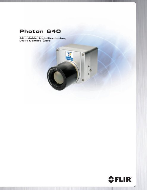
<strong>Photon</strong> <strong>640</strong><br />
Affordable, High-Resolution,<br />
LWIR LWIR Camera Core
2<br />
The Industry Standard Thermal Imaging Camera Core:<br />
For Applications Where Reliability and Performance are Priorities<br />
The <strong>Photon</strong> <strong>640</strong> Camera Core is a compact, all-in-one thermal imager with outstanding<br />
sensitivity and image quality. Its on-focal-plane circuitry, combined with FLIR’s advanced<br />
signal processing electronics, enables the camera to maintain excellent dynamic range<br />
and image uniformity over a wide temperature range.<br />
FLIR based its design of the <strong>Photon</strong> <strong>640</strong> core on the <strong>Photon</strong> 320 core. This proven<br />
design has been embedded in tens of thousands of <strong>Photon</strong> cores in a myriad of<br />
applications including automotive night vision systems, fi refi ghting equipment,<br />
unmanned vehicle payloads, thermal sights, low-power security & surveillance products,<br />
and more. The <strong>Photon</strong> <strong>640</strong> core provides four times as many pixels on target.<br />
<strong>Photon</strong> rear view of 30-pin connector.<br />
<strong>Photon</strong> <strong>640</strong> Part Number Table:<br />
Lens Version Video Format Part Number<br />
No Lens NTSC 412-0126-01-07<br />
No Lens PAL 412-0126-02-07<br />
21.5mm NTSC 412-0126-09-07<br />
21.5mm PAL 412-0126-10-07<br />
25mm NTSC 412-0126-03-07<br />
25mm PAL 412-0126-04-07<br />
35mm NTSC 412-0126-05-07<br />
35mm PAL 412-0126-06-07<br />
49mm NTSC 412-0126-11-07<br />
49mm PAL 412-0126-12-07<br />
60mm NTSC 412-0126-13-07<br />
60mm PAL 412-0126-14-07<br />
100mm NTSC 412-0126-15-07<br />
100mm PAL 412-0126-16-07<br />
NOTE 1: For Slow video (
<strong>Photon</strong> <strong>640</strong> Benefi ts<br />
• 2x resolution improvement over <strong>Photon</strong> 320 (4x number of pixels)<br />
• Widest operating temperature, and highest shock rating of any thermal camera<br />
• 2x and 4x digital zoom enables close-up imaging<br />
• Electronic Pan/Tilt in Zoom Mode<br />
•
4<br />
<strong>Photon</strong> <strong>640</strong> Accessory Kit<br />
For evaluation purposes, FLIR offers an optional Accessory<br />
Kit enabling customers to operate a <strong>Photon</strong> until they<br />
develop their own interface.<br />
The Kit contains a power supply, breakout box (called an I/O<br />
Module), an interface cable, and an EMI adapter board that<br />
provides a 26-pin D-sub connector to the camera providing<br />
for secure connection to the interface cable. The end-user<br />
only needs to provide a video cable, monitor, and an RS-232<br />
cable if remote control of the <strong>Photon</strong> is desired.<br />
Note: The EMI adapter board is required in order to use the<br />
<strong>Photon</strong> <strong>640</strong> Ethernet Module accessory.<br />
A camera control software program (GUI) is available for<br />
free download at:<br />
www.corebyindigo.com/service/softwareupdates.cfm<br />
<strong>Photon</strong> OEM Accessory Kit.<br />
<strong>Photon</strong> <strong>640</strong> rear view showing<br />
26-pin connector.<br />
<strong>Photon</strong> <strong>640</strong> Accessory Kit<br />
The <strong>Photon</strong> <strong>640</strong> OEM Accessory Kit part number is 421-0030-00. These items may also be ordered individually.<br />
Part Accessory Item Functional Description<br />
421-0030-00 <strong>Photon</strong> <strong>640</strong> OEM Accessory Kit consisting of:<br />
The Kit contains a power supply, breakout box (called<br />
an I/O Module), an interface cable, and an EMI<br />
421-0028-00 Adapter/EMI Cover Kit<br />
adapter board and cover providing a 26-pin D-sub<br />
connector to the camera for secure connection<br />
to the interface cable. The EMI adapter board is<br />
required in order to use the <strong>Photon</strong> <strong>640</strong> Ethernet<br />
Module accessory.<br />
333-0018-00 I/O Module<br />
206-0001-20 AC/DC Power Supply<br />
208-0004-02 Line Cord<br />
308-0144-02 Interface Cable
Optional Accessories<br />
Part<br />
Accessory Item Functional Description<br />
333-0017-00 <strong>Photon</strong> Serial/Parallel (SIPO) Module The SIPO converts serial digital data output into a parallel data<br />
format for use with a frame grabber. The SIPO mates directly<br />
to the I/O module’s digital data port, and furnishes a 68-pin<br />
connector.<br />
333-0018-00 <strong>Photon</strong> Camera Interface (I/O) Module A molded “break-out-box” providing electrical interface to the<br />
camera, connectors for power-in (Switchcraft), video-out (BNC),<br />
com port (RS-232, 9-pin D-Sub), and a 15-pin connector for serial<br />
LVDS digital data. The I/O Module is designed to mate with the<br />
SIPO for conversion of serial LVDS to a parallel digital data signal.<br />
206-0001-20 &<br />
208-0004-02<br />
308-0013-00<br />
308-0016-00-03<br />
308-0144-01<br />
308-0144-02<br />
308-0144-03<br />
308-0145-01<br />
308-0145-02<br />
308-0145-03<br />
P/S Unv Pwr in (100-240VAC) 9 Volts &<br />
110 VAC Line Cord<br />
Interface Cable, SIPO to NI PCI-1422<br />
Interface Cable, SIPO to Bit Flow Road<br />
Runner<br />
Cable Assy - <strong>Photon</strong> <strong>640</strong> Interface, 3ft<br />
Cable Assy - <strong>Photon</strong> <strong>640</strong> Interface, 6ft<br />
Cable Assy - <strong>Photon</strong> <strong>640</strong> Interface, 10ft<br />
Cable Assy - <strong>Photon</strong> <strong>640</strong> Power/Video, 3ft<br />
Cable Assy - <strong>Photon</strong> <strong>640</strong> Power/Video, 6ft<br />
Cable Assy - <strong>Photon</strong> <strong>640</strong> Power/Video, 10ft<br />
421-0008-00 THV A10 Battery Pack, Charger, & Cable Kit<br />
206-0002-10 Battery Pack 7.2 volts, Li-ion<br />
260-0007-10 Modified Battery Cable<br />
Provides nominal power (9 VDC) to operate the <strong>Photon</strong>.<br />
Either of these cables can be used with a SIPO (333-0008-00)<br />
to transfer digital data to the selected frame grabber. See www.<br />
corebyindigo.com/service/softwareupdates.cfm for camera files.<br />
The standard interface cable connects between the 26-pin D-Sub<br />
connector of the Adapter/EMI Cover and the I/O module. The<br />
standard interface cable provided with the Accessory Kit is 6ft.<br />
Interface cable from <strong>Photon</strong> camera providing connectors for<br />
power in and output video (only) available in 3ft, 6ft, and 10ft<br />
lengths. This cable replaces the standard interface cable and I/O<br />
module when serial control and digital video are not required.<br />
Rechargeable Lithium-Ion battery will power a <strong>Photon</strong> camera for<br />
6+ hours on a full charge. The battery is furnished with charger<br />
(not shown) and an 8” cable that interfaces to the I/O module.<br />
The nominal voltage output of the battery is 7.2 VDC.<br />
421-0028-00 Adapter/EMI Cover Kit - <strong>Photon</strong> <strong>640</strong> <strong>Photon</strong> <strong>640</strong> Adapter/EMI Cover Kit (44g)<br />
421-0031-00* Ethernet Kit consisting of:<br />
316-0015-05 Ethernet Adaptor Module<br />
308-0151-00 <strong>Photon</strong> 68 Pin to 26 Pin Cable<br />
415-0034-00, Cable, Power Assembly<br />
*Requires Adapter/EMI Cover Kit 421-0028-00<br />
This 100/1000 baseT Ethernet Interface module allows for<br />
camera control along with real-time streaming uncompressed<br />
video data from the <strong>Photon</strong> via standard ethernet hardware. The<br />
adapter auto senses network capability and runs at standard<br />
100-megabit or full gigabit ethernet speed. The module includes<br />
the ethernet interface adapter and camera cabling. The module<br />
allows capture of both 8-bit data and the full 14-bit bandwidth<br />
digital video. Analog video is also output via a BNC connector.<br />
261-2044-00 <strong>Photon</strong> <strong>640</strong> Tripod Adapter Adapter furnishes a ¼” x 20 helicoil insert.<br />
110-0102-46 <strong>Photon</strong> <strong>640</strong> SDK for windows & embedded The <strong>Photon</strong> SDK enables camera control using one of several<br />
programming languages including VB6, VB.net, C#, and C++<br />
(MFC). Code examples are included to help illustrate how some of<br />
the camera control functions can be used.<br />
110-0102-72 <strong>Photon</strong> Alt Lens Calibration Software Software for calibrating lens-less <strong>Photon</strong> cores with third-party<br />
optics.<br />
Specifications subject to change without notice.<br />
5
6<br />
Camera Confi gurations<br />
Stand Alone Operation with Accessory Kit<br />
Interface Cable<br />
<strong>Photon</strong> I/O Module Power Supply Monitor<br />
Accessory Kit and Customer-Furnished PC: Remote Operation<br />
DB-9 Serial Camera Control via RS-232<br />
Interface Cable<br />
<strong>Photon</strong><br />
I/O Module<br />
Power Supply Monitor PC<br />
Accessory Kit, SIPO and Customer-Furnished Desktop PC: Digital Data Collection<br />
DB-9 Serial<br />
I/O Module<br />
Camera Control via RS-232<br />
Interface Cable<br />
SIPO<br />
<strong>Photon</strong> Power Supply Monitor<br />
PC<br />
Custom Digital Data Cable<br />
NOTE: An appropriate frame grabber, as well as image acquisition & processing software, must be supplied and supported by the customer. The frame grabber may be either a<br />
Bit Flow Road Runner Model 14 or National Instruments PCI-1422 IMAQ, depending on the digital cable and type of software planned for use by the customer.<br />
Ethernet Module and Customer-Furnished PC: Digital Data Collection<br />
Interface Cable<br />
RJ-45 CAT-5 Camera Control & Digital Data<br />
<strong>Photon</strong> Ethernet Module Power Supply Monitor PC<br />
The Ethernet Module enables <strong>Photon</strong> control and video display/capture on a PC. Due to variability in user platforms and networks, FLIR cannot not guarantee the fi delity of captured video.<br />
Direct Interface to SAMTEC Connector<br />
Pin defi nitions of the 30-pin board connector for interface<br />
to the SAMTEC TFML-115-02-S-D-P connector (J1) are<br />
shown below. This is the primary connector interface to<br />
the <strong>Photon</strong> camera.<br />
Power Board to External I/O Connector Pin Defi nitions<br />
Pin # Signal Name Direction Signal Defi nition<br />
1 GND In Ground<br />
2 GND In Ground<br />
3 3.15V_OUT Out Output Voltage<br />
4 PWR_IN In Input Voltage<br />
5 GND In Ground<br />
6 GND In Ground<br />
7 2V_OUT Out Output Voltage<br />
8 N/C Out<br />
9 RS232_RX2 In Secondary Serial<br />
Communication receive,<br />
control input, 19200 baud<br />
(currently unavailable)<br />
10 RS232_RX1 In Primary Serial<br />
Communication receive,<br />
control input, 57600 baud<br />
Note: The mating connector is SAMTEC SFML-115-T1-S-D-K<br />
30<br />
29<br />
4 2<br />
3 1<br />
30-pin SAMTEC (M) connector on camera<br />
Pin # Signal Name Direction Signal Defi nition<br />
11 RS232_TX2 Out Secondary Serial<br />
Communication transmit,<br />
data output, 19200 baud<br />
(currently unavailable)<br />
12 RS232_TX1 Out Primary Serial<br />
Communication transmit,<br />
data output, 57600 baud<br />
13 N/C _ DO NOT CONNECT<br />
14 SD_DATA1- Out Digital Port 1 Output Data1;<br />
negative output<br />
15 N/C _ DO NOT CONNECT<br />
16 SD_ DATA1+ Out Digital Port 1 Output Data1;<br />
positive output<br />
17 N/C _ DO NOT CONNECT<br />
18 SD_FSYNC1- Out Digital Port 1 Sync; negative<br />
output<br />
19 N/C _ DO NOT CONNECT<br />
Note that FLIR’s<br />
pinout differs from<br />
SAMTEC pinout<br />
Pin # Signal Name Direction Signal Defi nition<br />
20 SD_FSYNC1+ Out Digital Port 1 Sync; positive<br />
output<br />
21 SD_DATA2+ Out Digital Port 1 Output Data2;<br />
positive output<br />
22 SD_CLK1- Out Digital Port 1 Clock;<br />
negative output<br />
23 SD_DATA2- Out Digital Port 1 Output Data2;<br />
negative output<br />
24 SD_ CLK1+ Out Digital Port 1 Clock; positive<br />
output<br />
25 Reserved DO NOT CONNECT<br />
26 DIS0_EXT In Frame Sync input<br />
27 DIS2_EXT In DO NOT CONNECT<br />
28 VIDEO_LO Out Analog Video -<br />
29 DIS1_EXT In DO NOT CONNECT<br />
30 VIDEO_HI Out Analog Video +
Lens Data<br />
Focal Length 21.5mm 25mm 35mm 49mm 60mm 100mm<br />
f/number 1.1 1.4 1.4 1.1 1.25 1.6<br />
Field of View 41° x 33° 36° x 29° 26° x 20° 19° x 14° 15° x 11° 9° x 7°<br />
IFOV (milliradians) 1.163 1.0 0.714 0.510 0.416 0.250<br />
Minimum Focus Distance ~4 meters** ~ 2 meters ~ 3 meters ~20 meters** ~2 meters ~10 meters<br />
Hyperfocal Distance 16 meters 13 meters 26 meters 81 meters 115 meters 160 meters<br />
Hyperfocal Depth of Field 7.8 meters 6.5 meters 13 meters 41 meters 58 meters 80 meters<br />
Weight (as pictured)* 318.0 g 298.5 g 299.1 g 542.0 g 370 g 664 g<br />
Length (Lens Only) 25.4 mm 30.2 mm 43.4 mm 54.6 mm 56.6 mm 111.8 mm<br />
Diameter (maximum) 45.2 mm 43.0 mm 42.0 mm 63.5 mm 61.5 mm 82.0 mm<br />
Coating Type Anti-Refl ective High Durability High Durability Anti-Refl ective DLC*** Hard Carbon<br />
Nominal Wavelength 8.0 to 14.0 microns<br />
*EMI board and cover installed.<br />
**It is not recommended that this lens be adjusted for close focus only imaging. Internal mechanical components in the lens can shift and not self re-align.<br />
*** Diamond-Like Coating<br />
Note: <strong>Photon</strong> lenses are not designed, calibrated, or specifi ed for close focus use. Questions? E-mail: cbi@fl ir.com<br />
Overview of the <strong>Photon</strong> <strong>640</strong> Electrical Interface<br />
<strong>Photon</strong> 26-pin D-Sub Connector Pin Defi nitions<br />
Pin # Signal Name Direction Signal Defi nition<br />
1 VIDEO_HI Out Analog Video +<br />
2 SIG GND In Signal Ground<br />
3 DIS0_EXT In Frame Sync Input<br />
4 DIS2_EXT In DO NOT CONNECT<br />
5 Reserved DO NOT CONNECT<br />
6 RS232_TX2 Out Secondary Serial Communication transmit, data output, 19200 baud (currently unavailable)<br />
7 RS232_RX1 In Primary Serial Communication receive, control input, 57600 baud<br />
8 GND Out Input Voltage GND<br />
9 PWR IN In Input Voltage<br />
10 VIDEO_LO Out Analog Video -<br />
11 N/C DO NOT CONNECT<br />
12 SD CLK1- Out Digital Port 1 Clock; negative output<br />
13 SD_FSYNCH1- Out Digital Port 1 Sync; negative output<br />
14 SD_DATA2+ Out Digital Port 1 Output Data2; positive output<br />
15 SD_DATA1- Out Digital Port 1 Output Data1; negative output<br />
16 RS232 GND Serial Communication ground<br />
17 N/C DO NOT CONNECT<br />
18 PWR_IN In Input Voltage<br />
19 DIS1_EXT In DO NOT CONNECT<br />
20 SD CLK1+ Out Digital Port 1 Clock; positive output<br />
21 SD_FSYNCH1+ Out Digital Port 1 Sync; positive output<br />
22 SD_DATA2- Out Digital Port 1 Output Data2; negative output<br />
23 SD_DATA1+ Out Digital Port 1 Output Data1; positive output<br />
24 RS232_RX2 In Secondary Serial Communication receive, control input, 19200 baud (currently unavailable)<br />
25 RS232_TX1 Out Primary Serial Communication transmit, data output, 57600 baud<br />
26 GND Out Input Voltage GND<br />
Specifi cations subject to change without notice.<br />
10<br />
19<br />
26-pin HD D-Sub (M)<br />
connector on camera<br />
1 9<br />
26<br />
18<br />
The 26-pin high-density D-Sub<br />
connector pin defi nitions are provided<br />
in the case that the Wearsaver<br />
adapter is used. The Wearsaver is<br />
an integral part of the EMI board, a<br />
<strong>Photon</strong> <strong>640</strong> camera accessory. The<br />
signals on this connector include<br />
input power, analogy video output,<br />
serial communication for camera<br />
control, and the digital data output.<br />
7
Specifi cations<br />
System Overview<br />
System Type Uncooled LWIR Thermal Imager<br />
Sensor Type <strong>640</strong> x 512 VOx Microbolometer<br />
Pixel Size 25 μm<br />
Spectral Band 7.5 – 13.5 μm<br />
Performance < 50mK NEdT at f/1.0, with FLIR proprietary noise reduction<br />
Outputs<br />
Analog Video NTSC @ 30 Hz<br />
PAL @ 25 Hz (optional)<br />
9 Hz option for export (factory set)<br />
Digital Video 8- or 14-bit serial LVDS<br />
Operation<br />
Image Control Invert, revert, 2x and 4x digital zoom,<br />
digital detail enhancement (DDE)<br />
Camera Control Autonomous, or manual via GUI or RS-232 serial command<br />
Signal Interface Power, video, communication, digital data, external sync,<br />
direct access to e-zoom & polarity<br />
Power<br />
Input Voltage Range 6-24 VDC<br />
Power Dissipation