Download (13.4 MB) - FULCRUM Wheels
Download (13.4 MB) - FULCRUM Wheels
Download (13.4 MB) - FULCRUM Wheels

You also want an ePaper? Increase the reach of your titles
YUMPU automatically turns print PDFs into web optimized ePapers that Google loves.
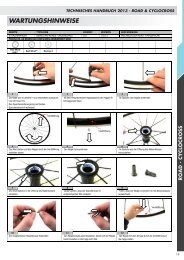
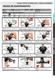
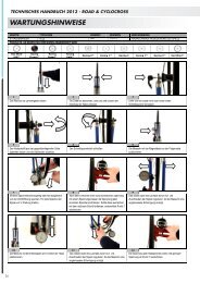
MAINTENANCE<br />
TECHNICAL MANUAL 2013 - ROAD & CYCLOCROSS<br />
GROUP TYPE OPERATION REVISION DESCRIPTION<br />
ROAD WHEELS CONE / CUP MECHANISM 002 1/2011 SERVICING FRONT HUB ASSE<strong>MB</strong>LY<br />
PRODUCTS ON WHICH THE PROCEDURE SHOULD BE APPLIED<br />
Red Wind<br />
XLR<br />
Racing<br />
Chrono<br />
Racing<br />
Speed<br />
Racing<br />
Light<br />
Racing 0 Racing 1 Racing 3<br />
1 2 3<br />
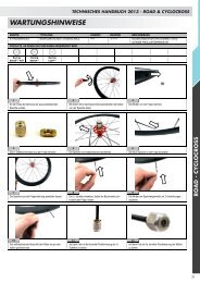
With a flat-bladed screwdriver remove the first<br />
protective cover. Make sure you do not damage the<br />
cover's locking teeth which would affect reassembling<br />
at a later stage.<br />
Once removed the cover, rotate the hub in the<br />
opposite direction.<br />
4 5 6<br />
Remove the cover. Using 2, 5mm hex wrenches to loosen the axles endcap/flange.<br />
7 8 9<br />
Loosen end cap (adjustment ring nut side). While removing the end cap, make sure you do not<br />
lose the spacer.<br />
With a flat-bladed screwdriver remove the second<br />
protective cover. Make sure you do not damage the<br />
cover's locking teeth which would affect reassembling<br />
at a later stage.<br />
Insert the two hex wrenches inside the hex-drive of<br />
the Of the axle and end cap then firmly unscrew. The<br />
right side (on the opposite side of the adjustment ring<br />
nut) remains fixed, the left side end cap rotates<br />
counter-clockwise to loosen the end cap.<br />
Use a screwdriver with a 2.5mm hexagon insert to<br />
loosen the screw of the adjustment ring nut.<br />
ROAD - CYCLOCROSS<br />
13
14<br />
TECHNICAL MANUAL 2013 - ROAD & CYCLOCROSS<br />
MAINTENANCE<br />
10 11 12<br />
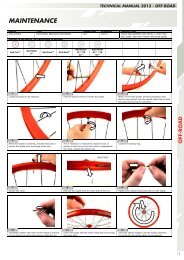
The indication that the adjustment ring nut will be<br />
loosened will be when the slot in the nut has a visible<br />
gap. Do not remove the screw from the adjustment<br />
ring nut.<br />
Holding the axle stationary, rotate the adjustment ring<br />
nut counter-clockwise to remove the adjustment ring<br />
nut.<br />
After removing the adjustment ring nut, you will see<br />
the cone and adjustment cone that we will remove in<br />
the next stage.<br />
13 14 15<br />
Push the axle into the hub body until it reaches the<br />
other side.<br />
The axle will easily come out from the opposite side. Remove the cone and the adjustment cone.<br />
16 17 18<br />
Protect all the components so that they do not get<br />
dirty to prevent any issues during reassembly.<br />
Remove the cone from the axle.<br />
►To replace the spokes see OPERATION 003<br />
►To replace the cones/cups, carry on until the end of<br />
the procedure.<br />
Remove the grease shield by using a small standard<br />
screwdriver. Repeat on the opposite side.<br />
19 20 21<br />
Make sure you do not damage the components. With a small screwdriver remove the bearing retaining<br />
ring making sure you do not damage it. Incorrect<br />
handling may cause the bearings to detach from the<br />
ring.<br />
Remove the cups using the special cup pulling tool.
MAINTENANCE<br />
22 23 24<br />
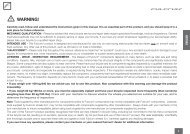
The cup pulling tool consists of two items. A specific<br />
stripper for road cups and a punch.<br />
TECHNICAL MANUAL 2013 - ROAD & CYCLOCROSS<br />
Insert the stripper inside the cup the cup that needs to<br />
be removed.<br />
25 26 27<br />
Insert the punch from the opposite side and fasten in<br />
the designated hole.<br />
Using a 12oz peen hammer, deliver solid precise blows<br />
to the striking end of the punch protruding from the<br />
hub shell.<br />
28 29 30<br />
Continue to deliver blows to the punch until the cup is<br />
removed from the hub shell.<br />
Take care to ensure that the cup stripper and punch<br />
are not propelled out of the hub when finally free of<br />
the hub shell.<br />
Once inserted correctly the stripper remains still<br />
without operator assistance. Rotate the hub in the<br />
opposite direction.<br />
Use care not to glance off of the punch as damage can<br />
occur to the wheel.<br />
Repeat from point 24 to remove the cup on the<br />
opposite side.<br />
31 32 33<br />
When removing the cups the grease shields may move<br />
away from their housings.<br />
Remove the grease shields on both sides. Check the integrity of the grease shield.<br />
ROAD - CYCLOCROSS<br />
15
16<br />
TECHNICAL MANUAL 2013 - ROAD & CYCLOCROSS<br />
MAINTENANCE<br />
CUP HOUSING<br />
GREASE SHIELD HOUSING<br />
34 35 36<br />
inspect the housing of the grease shield and of the cup If damaged, replace the grease shield. Insert the grease shield inside the body of the hub<br />
turning the concave part outwards.<br />
37 38 39<br />
Insert inside the body of the hub and underneath the<br />
designated housing of the grease shield.<br />
Manually drag the grease shield outwards. Lock the designated teeth on the housing of the<br />
grease shield.<br />
40 41 42<br />
Clean the cup thoroughly. Use the bearing insertion tool to fully insert the cups. Unscrew the insertion tool threaded handle.<br />
43 44 45<br />
Remove the adaptors. Insert the first cup on the adaptor. Place the cup/adaptor bearing press tool.
MAINTENANCE<br />
46 47 48<br />
Insert the tool inside the body of the hub. Make sure<br />
you do not damage the grease shields.<br />
TECHNICAL MANUAL 2013 - ROAD & CYCLOCROSS<br />
Place the second cup on the second adaptor. Tighten the cup.<br />
49 50 51<br />
Insert the second cup/adaptor onto the bearing press<br />
tool.<br />
Place the two cups on the body of the hub. Screw on the threaded handle to the bearing press<br />
tool.<br />
52 53 54<br />
Firmly close the two handles of the tool until the cups<br />
are fully inserted.<br />
Loosen the threaded handle. Remove the adaptor.<br />
55 56 57<br />
Remove the tool from the hub shell. Grease the surface of the ball track of the cup using<br />
the Campagnolo grease code LB-100.<br />
The amount of grease applied should cover about 75%<br />
of the space between the balls and the cups.<br />
ROAD - CYCLOCROSS<br />
17
18<br />
TECHNICAL MANUAL 2013 - ROAD & CYCLOCROSS<br />
MAINTENANCE<br />
58 59 60<br />
Insert the bearing retaining ring inside the cups body<br />
of the hub.<br />
Ensure that the bearing retaining ring is inserted into<br />
the cup with the ball bearings facing out.<br />
The hub shield must be undamaged. Replace if<br />
damaged.<br />
61 62 63<br />
The black part of the grease seal should face the Insert the grease seal inside the corresponding notch Repeat on the opposite side (from 62 to 68).<br />
inside of the hub's body.<br />
in the cup of the hub.<br />
64 65 66<br />
Insert the adjustment cone on the axle. Ensure that the cone seats properly onto the<br />
corresponding cone shape on the axle.<br />
Insert the axle inside the right side of the hub body.<br />
67 68 69<br />
Check the cone is mates correctly into the bearing<br />
retaining ring.<br />
Rotate the hub by 180°. Insert the second cone onto the axle following the<br />
direction it should be inserted in. The larger diameter<br />
should face the outside of the hub's body.
MAINTENANCE<br />
70 71 72<br />
Check the cone is mates correctly into the bearing<br />
retaining ring.<br />
TECHNICAL MANUAL 2013 - ROAD & CYCLOCROSS<br />
Insert the adjustment cone onto the axle mating into<br />
the cone from 69-70. The direction it should be<br />
inserted in. The larger diameter should face the<br />
outside of the hub's body.<br />
73 74 75<br />
Inspect the adjustment ring nut. If it is damaged,<br />
replace it.<br />
Install and tighten the adjustment ring nut clockwise<br />
and hold the axle while holding the axle stationary<br />
with your right hand.<br />
76 77 78<br />
Screw the axle end cap clockwise. Insert the two 5mm hex wrenches inside the hexagons<br />
of the hub's body and tighten firmly. The right wrench<br />
(on the opposite side of the adjustment ring nut)<br />
remains fixed, the left wrench rotates clockwise.<br />
Manipulate it into position by using a small<br />
screwdriver. Push the adjustment cone in by pressing<br />
on various points of the circumference.<br />
Inspect the axle end cap. If it is damaged, replace it.<br />
Insure that the small spacer is in place and install the<br />
end cap into the axle end.<br />
Inspect the dust covers. If they are damaged, replace<br />
them. Insert the cover with the larger internal<br />
diameter on the body of the hub on the adjustment<br />
ring nut side.<br />
79 80 81<br />
Make sure the cover engages correctly into place. Insert the cover with the smaller internal diameter on<br />
the body of the hub on the side opposite to the<br />
adjustment ring nut.<br />
Make sure the cover engages correctly into place.<br />
ROAD - CYCLOCROSS<br />
19
20<br />
TECHNICAL MANUAL 2013 - ROAD & CYCLOCROSS<br />
MAINTENANCE<br />
82 83<br />
Using a plastic hammer gently tap on both sides of the<br />
hub pin.<br />
►To adjust the hub see OPERATION 001