SL210i/SL212i - Flamingo Shop Serv
SL210i/SL212i - Flamingo Shop Serv
SL210i/SL212i - Flamingo Shop Serv

Create successful ePaper yourself
Turn your PDF publications into a flip-book with our unique Google optimized e-Paper software.
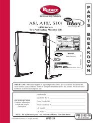
<strong>SL210i</strong>/<strong>SL212i</strong><br />
(500 Series)<br />
<strong>SL210i</strong> Fixed Pad Capacity 9,000 lbs.<br />
<strong>SL210i</strong> Capacity 10,000 lbs.<br />
<strong>SL212i</strong> Capacity 12,000 lbs.<br />
These Instructions Contain General Data. Any Deviation From Customers Prints<br />
Or Specifications Should Be Clarified Before Proceeding With Lift Installation.<br />
IMPORTANT Check the containment tube for holes due to shipping damage. Do not<br />
install a damaged containment tube. Contact Rotary Lift Customer <strong>Serv</strong>ice For<br />
Advice On How To Proceed. If the lift is where it has a chance to be exposed to the<br />
elements, protect the lift.<br />
© September 2004 by Rotary Lift. All rights reserved. LP20175<br />
IN20257<br />
Rev. D 09/15/2004<br />
I<br />
N<br />
S<br />
T<br />
A<br />
L<br />
L<br />
A<br />
T<br />
I<br />
O<br />
N<br />
I<br />
N<br />
S<br />
T<br />
R<br />
U<br />
C<br />
T<br />
I<br />
O<br />
N<br />
S
IMPORTANT<br />
<br />
<br />
<br />
<br />
<br />
<br />
2<br />
<br />
<br />
<br />
<br />
<br />
IMPORTANT Contact with the electrical heating coils could cause electrolysis and damage the lift and/or its<br />
components. Make sure the lift frame concrete anchors do not contact electrical heating coils, or re-bar that may be in<br />
contact with other embedded electrical sources. The lift being physically connected to any source which promotes<br />
electrolysis will void the warranty.
3/8" Airline (by Installing Contractor)<br />
To Reducing<br />
Male Branch Tee<br />
In-line Air Filter (by Rotary)<br />
Shut Off Valve<br />
(by Installing Contractor)<br />
1/2" Air Line to Compressor or<br />
Air Main (by Installing Contractor)<br />
In-Line Pressure Regulator/Water<br />
Separator (by Installing Contractor)<br />
1/4" Air Line To LDS Sensor<br />
Attaches To Female Connector on<br />
Pressure Switch In Back Of<br />
Master Control Panel ( by Rotary)<br />
IMPORTANT!!!:<br />
After Routing The<br />
Air Lines & Hydraulic Hose<br />
Do Not Cap Either End<br />
Of Pipe Chase. Air<br />
Must Vent Out<br />
In Order For<br />
LDS To Work Properly.<br />
Wheel Spotting<br />
Dish (by Rotary)<br />
Power Unit<br />
&<br />
Master Control Panel<br />
Mounted On Optional Pedestal<br />
Lift (by Rotary)<br />
3<br />
Electrical Power Supply<br />
(by Installing Contractor)<br />
Master Control Panel<br />
Power Unit Cover<br />
Power Unit (by Rotary)<br />
1/4" Air Line to Locking Latch<br />
And LDS Sensor (by Rotary)<br />
Hydraulic Hose to Lift<br />
(by Installing Contractor)<br />
PVC Conduit for Air and Hydraulic<br />
Hose (by Installing Contractor)<br />
Please follow these instructions to ensure a good installation and<br />
satisfactory operation of the lift. Check your shipment against the<br />
product load list and shipping papers. Enter claims for damage or<br />
shortage with the delivering carrier at once.<br />
• After installation, please return this booklet to the literature<br />
package and give to lift owner/operator.<br />
• Literature package should be kept attached to power unit for<br />
easy access.<br />
• Review entire installation instructions before beginning<br />
excavation.<br />
IMPORTANT The center cover is designed for foot traffic<br />
only.<br />
IMPORTANT Restrict all unauthorized persons from going<br />
near excavation. OSHA standard restricts anyone from getting in<br />
excavated hole, unless OSHA guidelines are followed. See<br />
OSHA Excavating Standard CFR 1926.
12'-0" Min. to<br />
Nearest<br />
Obstruction<br />
or Per<br />
Section 1c<br />
Wheel<br />
Spotting Dish<br />
2' 5"<br />
4' 4" Swing Arm Lifts<br />
4' 7" Fixed Pad Lifts<br />
WORK BENCH (TYPICAL)<br />
APPROACH<br />
PVC Conduit<br />
Entrance for Air<br />
& Hydraulic Hose<br />
NOTE: Adjust Entrance<br />
For Pedestal Mounting<br />
Installation See Fig. 8a<br />
Foot traffic only on center cover<br />
5'-6" Min. to nearest obstruction<br />
<strong>SL210i</strong> Series<br />
PVC Inlet Into Containment Tube<br />
1. Lift Location:<br />
A. Check architect’s layout if available. Lay out lift as shown in<br />
Fig. 1. Recommended floor slope is 1/16" per foot.<br />
Drain<br />
Drainage Direction<br />
Drainage Direction<br />
Recommended Floor Slope 0-1/16" Per Ft.<br />
B. <strong>SL210i</strong>: The 5' 6" centerline to side and 12' 0" centerline to<br />
front and rear dimensions should be maintained to provide<br />
adequate working space. The minimum overhead clearance<br />
should be 85" plus height of highest vehicle to be raised. 24' 0"<br />
length bay recommended. Other lengths may be used, provided<br />
ample clearance is maintained at each end of lift.<br />
<strong>SL212i</strong>: The 5' 6" centerline to side and 13' 0" centerline to front<br />
and rear dimensions should be maintained to provide adequate<br />
working space. The minimum overhead clearance should be 88"<br />
plus height of highest vehicle to be raised. 26' 0" length bay<br />
recommended. Other lengths may be used, provided ample<br />
clearance is maintained at each end of lift.<br />
C. Base Unit Lifts: If you are planning to install roll-on/wheel<br />
alignment runways, locate lift per instructions from superstructure<br />
manufacturer. Use superstructure manufacturer's instructions for<br />
fore and aft, side to side, and ceiling clearances.<br />
2. Excavation: Excavate hole to dimensions shown in Fig. 2.<br />
Dig trench for 2" PVC pipe between lift and power unit location.<br />
Trench should be dug 11" below finished floor grade. Air line<br />
and hydraulic hose to be contained in this 2" PVC pipe.<br />
4<br />
Fig. 1<br />
13'-0" Min. to<br />
Nearest<br />
Obstruction<br />
or Per<br />
Section 1c<br />
4' 8"<br />
WORK BENCH (TYPICAL)<br />
Wheel<br />
Spotting Dish<br />
2' 5"<br />
APPROACH<br />
PVC Conduit<br />
Entrance for Air<br />
& Hydraulic Hose<br />
NOTE: Adjust Entrance<br />
For Pedestal Mounting<br />
Installation See Fig. 8a<br />
5'-6" Min. to nearest obstruction<br />
<strong>SL212i</strong> Series<br />
PVC Inlet Into Containment Tube<br />
Foot traffic only on center cover<br />
3. Concrete Preparation:<br />
A. Run 2" PVC from Control Area to Containment Tube. PVC<br />
will enter the Containment Tube 9-1/2" below finished floor<br />
grade. Hole is centered horizontally in Containment Tube, Fig. 1.<br />
B. Box out a 5' x 10' area around where lift is to be located.<br />
NOTE: For multiple lift installations, boxed out areas will<br />
overlap. Dig continuous trench, see illustration below.<br />
C. Pour concrete floor ensuring not to get concrete in boxed out<br />
area.<br />
NOTE: By using this installation method, the RAI can more<br />
accurately set lift to proper grade relative to finished floor.<br />
Reference Page 2.<br />
Continuous Trench<br />
5'<br />
10'<br />
Lift Location<br />
Concrete Floor<br />
Lift Location<br />
4. Lift Setting:<br />
IMPORTANT Check the containment tube for holes due to<br />
shipping damage. Do not install a damaged containment tube.<br />
Contact Rotary Lift Customer <strong>Serv</strong>ice.<br />
A. Chain hoist must have capacity of 2,500 lbs. with a clear<br />
swing of 9' 0". Rig sling for unit, attaching to the shipping strap,<br />
Fig. 3, and lower assembly into hole. Center lift and be sure lift<br />
containment inlet is located as shown in Fig. 1.<br />
IMPORTANT Owner: Your Installer Is Responsible For The<br />
Concrete Floor Being Finished To Grade Angle, NOT To The Top<br />
Of The Lift, Fig. 5. Failure To Comply Will Void Warranty.<br />
10'
B. Bend frame anchors out perpendicular to concrete frame and<br />
downward approximately 45° to floor level, Fig. 2.<br />
C. Remove and retain (4) 1/2"-13NC x 2" HHCS (marked with<br />
X, Fig. 3). Insert 1/2" Threaded Rods x 18" lg. into the holes and<br />
secure in place using 1/2" flat washers and nuts, Fig. 4.<br />
D. Attach 6 x 6’s to support unit on existing floor and secure in<br />
place with 1/2" flat washers and nuts, Fig. 4. Remove shipping<br />
straps and install guide barrel bolts in open holes and torque to 60<br />
ft-lbs. Remove protective covers from top of jacks.<br />
NOTE: Make sure rubber thread protectors are still in place<br />
on all nuts welded to the concrete frame, including where the<br />
hardware was just added, Fig. 5.<br />
105"<br />
110"<br />
23-3/8"<br />
Frame<br />
36"<br />
2" PVC Pipe<br />
73-5/8"<br />
Frame Width<br />
96"<br />
Concrete<br />
Floor<br />
Frame Anchor<br />
18"<br />
Clean Pea<br />
Gravel Fill<br />
Wall Bracket<br />
77" Power<br />
Unit<br />
9-1/2"<br />
7,200 lbs. maximum reaction<br />
longitudinal and transverse<br />
direction due to eccentric loads<br />
Lift & Containment Tube<br />
Grade Angle<br />
Fig. 2<br />
6"-8"<br />
Jack<br />
5<br />
X<br />
Blocks<br />
X<br />
6 x 6's<br />
X<br />
X<br />
Shipping<br />
Straps<br />
(2) 1/2"-13NC x 18" lg. Threaded Rod,<br />
Flat Washers, & Nuts<br />
Machinist Level<br />
Lift and<br />
Containment Tube<br />
60"<br />
Thread<br />
Protectors<br />
Fig. 3<br />
Fig. 4<br />
Fig. 5
E. Plumb and level by placing machinist level on top of jack. Do<br />
Not plumb or level off unit frame. See Fig 5.<br />
F. Shore Lift Securely!<br />
G. Connect 2" PVC to containment tube, chamfer PVC entering<br />
containment tube seal and lubricate I.D. of seal with grease or oil<br />
to ease entry of PVC into seal. PVC pipe should extend into<br />
containment tube 1" maximum.<br />
NOTE: If your PVC pipe and containment inlet do not align,<br />
you may have to cut back PVC pipe, and attach 2" Flexible<br />
PVC to make connection. All PVC joints MUST be leak proof.<br />
H. Recheck plumb.<br />
X<br />
X<br />
X<br />
Tape Covers<br />
Over Plungers<br />
X<br />
Center Cover<br />
X<br />
Tape Covers<br />
Over Plungers X<br />
X<br />
X X<br />
5. Backfill:<br />
A. Duct tape joint areas indicated by X, Fig. 6, to protect these<br />
areas during backfill and concrete work. Backfill around unit<br />
using only pea gravel to within 18" of top of finished floor.<br />
Fig. 6<br />
IMPORTANT Make sure thread protectors (supplied by Rotary)<br />
are on the underneath side of the concrete frame on all the bolts in<br />
the guide barrel and cover, Fig. 5.<br />
CAUTION Do not use a mechanical tamper or saturate the<br />
backfill material to achieve compaction. This could cause lift<br />
containment sides to bend inward, HAND TAMP ONLY.<br />
IMPORTANT Do Not fill plunger with any ballast material.<br />
*High Early is a registered trademark of General Portland Cement<br />
Company.<br />
Concrete<br />
Floor<br />
6<br />
X<br />
B. Complete backfill and tamp pipe trench.<br />
C. After lift is backfilled, make final elevation and plumb<br />
checks, Fig 5.<br />
D. Make sure frame anchors are bent out, Fig. 7.<br />
6. Concrete Work:<br />
A. Leave 6 x 6's in place.<br />
B. New concrete around the lift must be keyed into<br />
existing floor with rebar or stud anchors, Fig. 7.<br />
C. A minimum concrete strength of 3,000 PSI is<br />
suggested. DO NOT use calcium chloride as a curing<br />
accelerator. If using a curing accelerator, we recommend<br />
a non-chloride additive such as High Early* or equivalent.<br />
D. Pour concrete floor, being careful not to run concrete<br />
in and around top surface of lift unit.<br />
IMPORTANT Owner: Your Installer Is Responsible<br />
For The Concrete Floor Being Finished To Grade Angle,<br />
NOT To The Top Of The Lift, Fig. 7. Failure To Comply<br />
Will Void Warranty.<br />
IMPORTANT It is imperative that lift be set level<br />
regardless of floor slope or other factors. Trowel smooth<br />
and allow to harden.<br />
E. After concrete is set-up, remove 6 x 6's and threaded<br />
rods.<br />
F. Reinstall the guide barrel bolts, use Loctite 242 (blue)<br />
on bolts and torque to 60 ft.-lbs.<br />
G. Do not use lift until concrete has achieved 3,000 PSI.<br />
Grade Angle<br />
Bend Out<br />
Frame Anchors<br />
Rebar or Stud Anchor<br />
Lift and<br />
Containment Tube<br />
Fig. 7
7. Power Unit:<br />
A. Wall Mounting: For operating convenience, locate Power<br />
Unit wall mounting bracket so top of bracket will be<br />
approximately 77" above floor, Fig. 2.<br />
B. Locate and mount the wall bracket, using (4) 3/8" wall<br />
anchors, on the wall, Fig. 8. Anchors must be able to hold 20 lbs.<br />
of shear force.<br />
C. Put (4) 5/16"-18NC x 1-1/2" HHCS through wall bracket<br />
using push-nuts to hold in place, Fig. 8.<br />
D. Mount power unit, with motor up, to the wall bracket and<br />
install (4) 5/16" nuts and lock washers, Fig.8.<br />
E. Pedestal Mounting: Pedestal must be anchored to the floor<br />
with 3/8" anchor bolts before attaching power unit. Assemble<br />
stand, adapter rack bracket, and adapter rack as show, Fig. 8a.<br />
F. Use base for pattern to mark holes for anchoring. Pedestal<br />
must be anchored at least 30" away from the any obstacle to allow<br />
for wiring and maintenance of the power unit, Fig 8b.<br />
G. Put (4) 5/16"-18NC x 1-1/2" HHCS through power unit<br />
bracket using push-nuts to hold in place, Fig. 8b.<br />
H. Mount power unit, with motor up, to the power unit bracket<br />
and install (4) 5/16" nuts and lock washers, Fig.8b.<br />
8. Hose And Elbow Attachment (Hose Provided By<br />
Installer):<br />
A. Hose must meet Dayco EZ Flex 150 or equivalent specs. with<br />
3,000 PSI minimum working pressure, 3/8" I.D. with 9/16-<br />
18THD, JIC fitting, female swivel ends.<br />
B. Hose must be free of debris. Inspect all threads for damage.<br />
C. Install hose onto elbow adapter on power unit, Fig. 9.<br />
D. Do not route hose to lift at this time.<br />
Use (4)5/16"-18NC<br />
x 1-1/2" lg. HHCS<br />
Push nuts hold<br />
bolts to brackets<br />
Fill Breather Cap<br />
Use (4)5/16"-18NC<br />
Nuts and 5/16" Star<br />
Washers<br />
Lowering<br />
Valve<br />
Fig. 8<br />
7<br />
Use (4)5/16"-18NC<br />
x 1-1/2" lg. HHCS<br />
Push nuts hold<br />
bolts to brackets<br />
Fill Breather Cap<br />
3/8" - 16NC x 3-1/2"<br />
HHCS, Lockwasher,<br />
& Nut<br />
5/16"-18NC x 3/4"<br />
HHCS and Nut<br />
Use (4)5/16"-18NC<br />
Nuts and 5/16" Star<br />
Washers<br />
Lowering<br />
Valve<br />
30" From Nearest Obstacle<br />
Elbow Adapter<br />
Crimped Hose<br />
Sleeve (Typical)<br />
Anchor Pedestal<br />
To Floor with 3/8"<br />
Anchor Bolts Before<br />
Attaching Power Unit<br />
Power Unit Hose<br />
to Lift. Hose must<br />
meet Dayco EZ<br />
Flex 150 or equiv.<br />
Specs . with 3,000<br />
PSI min. working<br />
pressure, 3/8" I.D.<br />
with 9/16-18THD<br />
JIC Fitting, Female<br />
Swivel Ends.<br />
Fig. 8a<br />
Fig. 8b<br />
Fig. 9
9. Mounting Power Unit Cover:<br />
A. Attach female bulkhead fitting to power unit cover and install<br />
reducing male branch tee to the back of the bulkhead fitting with<br />
the 3/8” opening facing towards the floor, Fig. 10.<br />
B. Mount tool holder to preferred side of power unit cover, with<br />
(2) 5/16”-18NC x 3/4” bolts and nuts.<br />
C. Align the access hole in the power unit cover with the junction<br />
box on the power unit, Fig 10.<br />
D. Mount the power unit cover, using (4) 3/8" wall anchors, on<br />
the wall. Anchors must be able to hold 20 lbs. of shear force.<br />
10. Mounting Master Control Panel:<br />
A. Wall Mount: Remove Access Panel from Master Control<br />
Panel, Fig.10.<br />
B. Place (2) 5/16"-18NC x 3/4" HHCS and (2) 5/16"-18NC hex<br />
nuts through holes in front of power unit cover, Fig. 10. Leave<br />
screws and nuts loose enough to allow you to hang master control<br />
panel.<br />
C. Route air lines and cords from rear of master control panel<br />
through access cut out in power unit cover, Fig. 10.<br />
D. Hang master control panel on power unit cover from the two<br />
loose bolts and nuts, Fig. 10. Place (1) 5/16"-18NC x 3/4"<br />
HHCS and (1) 5/16"-18NC hex nut through bottom of master<br />
control panel and tighten, Fig 10. Tighten top two nuts and bolts<br />
to secure the master control panel.<br />
This Access Cut Out<br />
Must Line Up With<br />
Junction Box On Motor<br />
5/16"-18NC x 3/4" HHCS<br />
& 5/16" Nuts<br />
Tool Holder Can Be Mounted<br />
On Either Side Of<br />
Power Unit Cover<br />
Reducing Male Branch Tee<br />
3/8" Opening Facing Down<br />
8<br />
E. Pedestal Mount: Remove Access Panel from Master Control<br />
Panel, Fig.10.<br />
F. Place (2) 5/16"-18NC x 3/4" HHCS and (2) 5/16"-18NC hex<br />
nuts through holes in front of master control bracket, Fig. 10a.<br />
Leave screws and nuts loose enough to allow you to hang master<br />
control panel.<br />
NOTE: Before hanging master control panel on pedestal<br />
attach female bulkhead to master control bracket and install<br />
reducing male branch tee to back of the bulkhead with the 3/<br />
8” opening facing towards the floor, Fig. 10a.<br />
G. Route air lines and cords through hole in master control<br />
bracket Fig. 10a.<br />
H. Hang control panel from the two loose bolts and nuts, Fig.<br />
10a. Place (1) 5/16"-18NC x 3/4" HHCS and (1) 5/16"-18NC<br />
hex nut through bottom of master control panel and tighten, Fig<br />
10a. Tighten top two nuts and bolts to secure the master control<br />
panel. Leave access panel off of master control panel until all air<br />
and electric connections are made.<br />
Note: All Nuts And Bolts For Mounting The Tool<br />
Holder And Master Contol Panel are 5/16"-18NC<br />
5/16"-18NC x 3/4" HHCS<br />
& 5/16" Nuts<br />
Power Unit Cover<br />
Master Control Panel<br />
Cord To Main<br />
Power Supply<br />
Female Bulkhead Fitting<br />
Female Bulkhead Nut<br />
Access<br />
Panel<br />
Fig. 10
Route Cords<br />
And Hoses Through<br />
Hole In Master Control<br />
Bracket Before Hanging<br />
Master Control Panel<br />
5/16"-18UNC Hex Nut<br />
Female Bulkhead Nut<br />
Male Branch Tee<br />
3/8" Opening<br />
Facing Down<br />
3'<br />
5/16"-18UNC Hex Nut Note: Attach Top Two<br />
Nuts And Bolts First.<br />
Leave Them Loose<br />
Enough To Hang<br />
Master Control Panel.<br />
5/16"-18NC x 3/4" HHCS<br />
9<br />
Access Panel<br />
5/16"-18NC x 3/4" HHCS<br />
Female Bulkhead Fitting<br />
Optional Pedestal Mount<br />
Fig. 10a
11. Electrical:<br />
Have a certified electrician run appropriate motor voltage. Size<br />
wire for 25 amp circuit. See Motor Operating Data Table.<br />
For Models with GFCI Electrical Outlets: The<br />
certified electrician should also run a seperate 110V 60Hz line<br />
to the junction box. Wire size for 15 amp circuit.<br />
IMPORTANT DO NOT drop one leg from the motor supply, it<br />
may cause damage to the controls.<br />
CAUTION Never operate the motor on line voltage less than<br />
208V. Motor damage may occur.<br />
IMPORTANT Use separate circuit for each power supply.<br />
Protect each circuit with time delay fuse or circuit breaker. For<br />
single phase 208-230V, use 25 amp fuse, and three phase use 20<br />
amp fuse. For three phase 460V, use 10 amp fuse. All wiring<br />
must comply with NEC and all local electrical codes.<br />
Note: Standard single phase motor CAN NOT be run on 50Hz.<br />
line without a physical change in the motor.<br />
Wire motor according to wiring diagrams provided on pages 11<br />
and 14.<br />
As with all electronic equipment, the Inbay<br />
control modules can be affected by voltage irregularities. It is<br />
the lift owner's responsibility to ensure that adequately<br />
protected power sources are available for connecting this<br />
equipment.<br />
Plug Lowering Valve cord from master control panel into<br />
lowering valve on power unit, Fig. 11.<br />
Lowering Valve Cord<br />
From Master Control Panel<br />
Plugs Into Lowering Valve<br />
Tighten Screw On<br />
Top Of Plug After<br />
Plugging In<br />
<strong>Serv</strong>ice From<br />
Master Control Panel<br />
(3 Wire) Into Junction<br />
Box On Power Unit<br />
Attach With Strain<br />
Relief Provided<br />
Fig. 11<br />
10<br />
Single Phase Rotary Power Unit<br />
MOTOR OPERATING DATA - SINGLE PHASE<br />
LINE VOLTAGE RUNNING MOTOR VOLTAGE RANGE<br />
208 - 230 Volts 60 HZ 197 - 253 Volts<br />
From Master<br />
Control Panel<br />
Attach ground wire here.<br />
Attach ground wire to<br />
screws provided.<br />
Attach black wire<br />
to black wire.<br />
Attach white<br />
wire to white wire.<br />
Three Phase Rotary Power Unit<br />
MOTOR OPERATING DATA - THREE PHASE<br />
LINE VOLTAGE RUNNING MOTOR VOLTAGE RANGE<br />
208 - 230 Volts 60 HZ 197 - 253 Volts<br />
460 Volts 60 HZ 414 - 506 Volts<br />
575 Volts 60 HZ 518 - 632 Volts<br />
NOTES:<br />
1. Unit not suitable for use in unusual conditions. Contact<br />
Rotary for moisture and dust environment duty unit.<br />
2. Verify Coil Rating Matches Supply Voltage<br />
3. Motor rotation is counter clockwise when viewed from top of<br />
motor.
11<br />
Single Phase Wiring Schematic (without GFCI)
Single Phase Wiring Schematic (with GFCI)<br />
12
13<br />
Three Phase Wiring Schematic (without GFCI)
Three Phase Wiring Schematic (with GFCI)<br />
14
Routing Supply Lines<br />
3/8" Airline (by Installing Contractor)<br />
To Reducing<br />
Male Branch Tee<br />
In-line Air Filter (by Rotary)<br />
Shut Off Valve<br />
(by Installing Contractor)<br />
1/2" Air Line to Compressor or<br />
Air Main (by Installing Contractor)<br />
In-Line Pressure Regulator/Water<br />
Separator (by Installing Contractor)<br />
1/4" Air Line To LDS Sensor<br />
Attaches To Female Connector on<br />
Pressure Switch In Back Of<br />
Master Control Panel ( by Rotary)<br />
IMPORTANT!!!:<br />
After Routing The<br />
Air Lines & Hydraulic Hose<br />
Do Not Cap Either End<br />
Of Pipe Chase. Air<br />
Must Vent Out<br />
In Order For<br />
LDS To Work Properly.<br />
Wheel Spotting<br />
Dish (by Rotary)<br />
Lift (by Rotary)<br />
12. Supply Lines (By Installer): Remove duct tape and center<br />
cover. Set Bolts and seal aside, taking care not to damage seal.<br />
A. Hose:<br />
1. Push the hose through the 2" PVC pipe chase from power<br />
unit to lift unit, Fig 12 & Fig. 14.<br />
2. Install to hydraulic fitting in lift containment inlet.<br />
B. Air Lines:<br />
1. Remove access panel from control panel.<br />
2. Install in-line air filter and run 3/8” air line to reducing<br />
male branch tee on female bulkhead located on the power unit<br />
cover or (master control bracket for pedestal option) , Fig. 12.<br />
3. Cut to fit 1/4” air line and attach it to the reducing male<br />
branch tee and inline regulator in back of master control<br />
panel, Fig. 13.<br />
4. Attach (1) 1/4" push-in NPT coupling to 1/4” (#2) air line<br />
running from the air valve in the master control panel, Fig.13.<br />
5. Attach 1/4" polypropylene tubing to other end of 1/4"<br />
push-in NPT coupling and push the tubing though the 2" PVC<br />
pipe chase to the lift, Fig. 14.<br />
Electrical Power Supply<br />
(by Installing Contractor)<br />
15<br />
Master Control Panel<br />
Power Unit Cover<br />
Power Unit (by Rotary)<br />
1/4" Air Line to Locking Latch<br />
And LDS Sensor (by Rotary)<br />
Hydraulic Hose to Lift<br />
(by Installing Contractor)<br />
PVC Conduit for Air and Hydraulic<br />
Hose (by Installing Contractor)<br />
Power Unit &<br />
Master Control Panel<br />
Mounted On Optional Pedestal<br />
Center Cover<br />
*LDS = Liquid Detection System<br />
Fig. 12<br />
6. Attach 1/4" polypropylene tubing into pressure switch,<br />
Fig. 13.<br />
7. Push the tubing through the 2” PVC pipe chase to the<br />
LDS* valve assembly, Fig. 14.<br />
8. The shortest air line coming from the air valve in the<br />
master control panel is for exhaust only.<br />
9. Cut to fit 1/4” air line and run it from the male tee inside<br />
the lift to the top elbow of the LDS* assembly, Fig.14.<br />
NOTE: All 1/4” polypropylene air line must have a 300 PSI<br />
working pressure.<br />
IMPORTANT Failure to connect air lines properly will cause a<br />
fault error on the master control panel.<br />
IMPORTANT After routing the air lines and hydraulic hose DO<br />
NOT cap either end of the PVC conduit. Air must vent out in<br />
order for the LDS* to work properly, Fig 14.
1/4" Push-in<br />
NPT Fitting<br />
Air Line Tubing<br />
Fig. 13<br />
2<br />
Air Valve<br />
3<br />
(#2)1/4" Air Line To<br />
Air Tee in Containment<br />
Tube On Lift Frame<br />
1<br />
Air Line Fitting Connection<br />
Replace Access Panel<br />
After Connections Are Made<br />
1/4" Exhaust Air Line<br />
Remove<br />
The Four<br />
1/4"-20NC x 1/2"<br />
Flg. Soc BHCS<br />
From Master Control Cover<br />
16<br />
1/4" Air Line From<br />
Reducing Male Branch Tee<br />
To Inline Regulator<br />
Inline<br />
Regulator<br />
Pressure<br />
Switch<br />
Bulkhead<br />
1/4" Air Line From<br />
Pressure Switch To<br />
LDS Valve Assembly<br />
In Containment Tube<br />
1/4" Air Line From<br />
Reducing<br />
Male Branch Tee<br />
To Inline Regulator<br />
Reducing Male<br />
Branch Tee<br />
3/8"Air Line Into<br />
Reducing Male Branch Tee
Hydraulic Hose<br />
Attaches To Hydraulic Fitting<br />
In Lift Containment Inlet<br />
PVC Conduit<br />
Back To Master Control Panel<br />
IMPORTANT!!!:<br />
After Routing The<br />
Air Lines & Hydraulic Hose<br />
Do Not Cap Either End<br />
Of PVC Conduit. Air<br />
Must Vent Out<br />
In Order For<br />
LDS To Work Properly.<br />
17<br />
(#2) 1/4" Hose From Air Valve<br />
In Master Control Panel<br />
Plugs Into Male Tee<br />
CONTAINMENT<br />
NOT SHOWN<br />
FOR CLARITY<br />
OF VIEW<br />
Cut To Fit 1/4" Hose From<br />
Male Tee to<br />
LDS Valve Assembly<br />
LDS Valve Assembly<br />
1/4" Hose From<br />
Pressure Switch In<br />
Master Control Panel<br />
Fig. 14
Insert 4" and 8"<br />
Extensions Into Racks<br />
Adapter Extension Racks<br />
Raise Lift / Scroll Up<br />
Lower Lift / Scroll Down<br />
18<br />
00/00/00 00:00<br />
Menu Selection / Lower To Locks<br />
Tab Can Be Pulled<br />
Out Of Switch To<br />
Lock Disconnect<br />
In OFF Position<br />
FF<br />
1 ON<br />
Mode Button<br />
Fig. 15
13. Adapter Extension Racks (For SL212 only):<br />
A. Locate and mount adapter extension racks on the wall<br />
convenient to the bay area using (4) 3/8" wall anchors. Anchors<br />
must be able to hold 20 lbs. of shear force.<br />
B. Place 4" and 8" extensions into racks.<br />
14. Power Up: Turn disconnect to ON position from the master<br />
control panel, Fig. 17.<br />
15. Setup Screen:<br />
A. Use up, down, and select buttons to select language, Fig. 17.<br />
B. Use up, down, and select buttons to select lift type.<br />
C. Use up, down, and select buttons to set day and time.<br />
16. Fluid Filling:<br />
A. System capacity is 19 quarts. Use Dexron III ATF, or<br />
Hydraulic Fluid that meets ISO 32 specifications.<br />
B. Remove fill-breather cap, Fig. 8.<br />
C. Add fluid to power unit until it reaches the MIN_____<br />
mark on the tank.<br />
D. Press on touch pad and raise lift to full rise, Fig. 15.<br />
E. Press on touch pad to fully lower lift, Fig. 15.<br />
F. Bleed lift by cycling to full rise several times.<br />
G. Top off fluid to power unit until it reaches the MIN_____<br />
mark on the tank.<br />
IMPORTANT All lifts must be fully lowered before<br />
changing or adding fluid.<br />
CAUTION If fill-breather cap is lost or broken, order a<br />
replacement. DO NOT substitute with a solid plug.<br />
17. Locking Latch Test; refer to Fig. 15:<br />
A. Press on the touch pad and raise lift in up position,<br />
press<br />
SELECT<br />
LOWER TO LOCKS<br />
and lower lift onto locks.<br />
B. Make sure latch engages and releases.<br />
18. Cylinder/Load Pad Test; refer to Fig. 15:<br />
A. Press on touch pad and raise lift to full rise and press<br />
SELECT<br />
LOWER TO LOCKS<br />
to lower onto locks.<br />
B. Look into the containment tube to check that the high pressure<br />
cylinder rod is in the load pad hole, Fig. 16.<br />
C. If not, use a nonmetal object (do not scratch or scar the<br />
cylinder rods), try to move the cylinder rod. If it does not move<br />
skip step D.<br />
19<br />
Hydraulic<br />
Hose<br />
Bulkhead Fitting<br />
Cylinder Rod Boss<br />
Load Pad<br />
Fig. 16<br />
19. Hose Tracking Test:<br />
Have someone raise the lift while another watches the tracking of<br />
the hose between the bulkhead fittingd and equalizer beam, Fig.<br />
17. If the hose does not track between the members of the<br />
equalizer beam without rubbing, adjust bulkhead fitting as<br />
necessary.<br />
Equalizer<br />
Beam<br />
Fig. 17
20. Setting Cover; refer to Fig. 22:<br />
A. Insert cover seal into lip in opening, making sure all holes<br />
align.<br />
B. Install center cover onto seal.<br />
C. Install and tighten cover retaining bolts. Torque to 60 ft-lbs.<br />
IMPORTANT Clean areas indicated with X, Fig. 18, and seal<br />
with a premium 25 year silicone.<br />
X<br />
Fig. 19<br />
Short Arms<br />
7/8"-10NC x 3-1/2" HHCS<br />
and 3/4" External Tooth<br />
Lockwasher<br />
APPROACH<br />
Plug Button<br />
Long Arms<br />
Please note locations of long and short arms in relation to<br />
approach. N/A for lifts with (4) short arms.<br />
Fig. 20<br />
X<br />
X<br />
Fig. 18<br />
X<br />
X X<br />
X<br />
X X<br />
Center Cover<br />
Arm Pin<br />
Snap Ring<br />
Swing Arm Superstructure<br />
20<br />
X<br />
21. Superstructure:<br />
Sl210i Series:<br />
A. Base Unit Lifts: Install roll-on/wheel alignment<br />
runway per instructions from superstructure<br />
manufacturer.<br />
B. Swing Arm Superstructures: Note arm locations,<br />
Fig. 19.<br />
1. Install yokes to plungers with 7/8"-10NC x 3-1/<br />
2" HHCS and lock washer. Torque to 150 ft-lbs,<br />
Fig. 20.<br />
2. Grease swivel arm pins and arm holes with<br />
Lithium grease.<br />
3. Install (4) arm assemblies using the arm pins and<br />
snap rings.<br />
Note arm locations, Fig. 19.<br />
C. Fixed Pad Assemblies:<br />
1. Install pads on lift using 7/8”-10NC x 3-1/2”<br />
HHCS and 3/4” external tooth lockwasher and<br />
torque to 150 ft.-lbs, Fig.21.<br />
<strong>SL212i</strong> series:<br />
A. Base Unit Lifts: Install roll-on/wheel alignment<br />
runway per instructions from superstructure<br />
manufacturer.<br />
B. Swing Arm Superstructures:<br />
1. Install yokes to plungers with 7/8"-9NC x 3-1/2"<br />
HHCS and lock washer. Torque to 150 ft-lbs., Fig.<br />
22.<br />
2. Grease swivel arm pins and arm holes with<br />
Lithium grease.<br />
3. Install (4) arm assemblies using the arm pins and<br />
cotter pins, Fig. 23.<br />
22. Final Touches:<br />
A. Lag wheel spotting dish to floor using two 3/8”<br />
anchors provided. Verify model number of lift being<br />
installed and refer to Fig. 1 for respective dimensions.<br />
B. Raise lift and clean sand and dirt from plunger and<br />
lift area.<br />
C. Double check to make sure the guide barrel and<br />
center cover are sealed per Step 20.
7/8"-9NC x 3-1/2" HHCS &<br />
External Tooth Lockwasher<br />
7/8"-10NC x 3-1/2" HHCS<br />
and 3/4" External Tooth<br />
Lockwasher<br />
Fixed Pad Superstructure<br />
Arm Pin<br />
Fig. 23<br />
21<br />
Fig. 21<br />
Fig. 22<br />
Cotter Pin
Notes:
Notes:
Installer: Please return this booklet to<br />
literature package, and give to lift<br />
owner/operator.<br />
Thank You<br />
Trained Operators and Regular Maintenance Ensures Satisfactory<br />
Performance of Your Rotary Lift.<br />
Contact Your Nearest Authorized Rotary Parts Distributor for Genuine Rotary Replacement<br />
Parts. See Literature Package for Parts Breakdown.<br />
DATE REV. CHANGE MADE<br />
09-10-03 - New 500 Series.<br />
06-07-04 C Update wiring diagrams, remove writing/storage shelf and add fixed pad<br />
capactiy to title page.<br />
09/15/2004 D Add GFCI.<br />
World Headquarters:<br />
Rotary,<br />
2700 Lanier Drive<br />
Madison, Indiana USA<br />
www.rotarylift.com<br />
® Rotary Lift. Printed in U.S.A., All Rights Reserved. Unless otherwise indicated, ROTARY,<br />
DOVER and all other trademarks are property of Dover Corporation and its affiliates.<br />
Phone: 1.800.445.5438<br />
Phone: 1.812.273.1622<br />
Fax: 1.800.578.5438<br />
Fax: 1.812.273.6502<br />
userlink@rotarylift.com<br />
World Wide Contact Information:<br />
Canada: 905.812.9920<br />
Germany: +49.771.9233.0<br />
United Kingdom: +44.178.747.7711<br />
Australasia: +60.3.7660.0285<br />
Latin America/Caribbean: 1.812.273.1622<br />
Middle East/South Africa: 1.812.273.1622