timers monitors electric devices for installation - GANZ Kapcsoló- és ...
timers monitors electric devices for installation - GANZ Kapcsoló- és ...
timers monitors electric devices for installation - GANZ Kapcsoló- és ...

You also want an ePaper? Increase the reach of your titles
YUMPU automatically turns print PDFs into web optimized ePapers that Google loves.
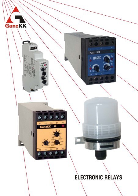
ELECTRONIC RELAYS
When the function or the time-range changes during the<br />
delay time, the time-range changes immediately, the<br />
function (operating characteristic) changes after the<br />
passing of the delay time.<br />
Red LED indicates making position of the relay.<br />
Green LED to indicate of the control voltage<br />
Choise of range of delay time<br />
position of the switches: 0,1-1 s, 1-10 s,<br />
0,1-1 min, 1-10 min<br />
0,1-1 hour, 1-10 hour,<br />
0,1-1 day, 1-10 days,<br />
relay ON, relay OFF<br />
Fine adjustment of time<br />
Switch <strong>for</strong> choice of the function:<br />
a Delay in making<br />
(power starting)<br />
b Delay in breaking<br />
(power starting)<br />
c Program switch<br />
(begins with breaking relay)<br />
d Program switch<br />
(begins with making relay)<br />
e Delay in switch-off<br />
(starting by contacts)<br />
f Delay in breaking<br />
(controlled by impulse)<br />
g Stepping<br />
(starting by contacts)<br />
h Delay in making and<br />
delay in switch-off<br />
(starting by contacts)<br />
i Impulse relay<br />
(starting by contacts)<br />
j Impulse generator<br />
(power starting)<br />
CRM-91H and CRM-93H multifunctional <strong>timers</strong><br />
U<br />
U<br />
U<br />
U<br />
U<br />
S<br />
U<br />
S<br />
U<br />
S<br />
U<br />
S<br />
U<br />
S<br />
U<br />
t t<br />
t<br />
t<br />
t<br />
t<br />
t<br />
t<br />
t<br />
t<br />
t<br />
t<br />
t<br />
t<br />
t t<br />
t<br />
t t t<br />
t<br />
t<br />
t<br />
t<br />
t<br />
t<br />
A1 S A2<br />
<strong>GANZ</strong> KK<br />
Un<br />
Connecting<br />
1-10m<br />
0.1-1m<br />
1-10s<br />
ON<br />
0.1-1s<br />
OFF<br />
.4 .5 .6<br />
.3<br />
.7<br />
.8<br />
.2<br />
.9<br />
.1<br />
1<br />
0.1-1h 1-10h<br />
0.1-1d<br />
1-10d<br />
c<br />
b<br />
a<br />
d e f g<br />
h<br />
i<br />
j<br />
TIME<br />
FUNC<br />
CRM-91H<br />
15 16 18<br />
A1 S A2<br />
35 36 38<br />
<strong>GANZ</strong> KK<br />
Un<br />
c<br />
b<br />
a<br />
d e f 1-10m<br />
0.1-1m<br />
1-10s<br />
ON<br />
0.1-1s<br />
OFF<br />
.4 .5 .6<br />
.3<br />
.7<br />
.8<br />
.2<br />
.9<br />
.1<br />
1<br />
g<br />
h<br />
i<br />
j<br />
0.1-1h 1-10h<br />
0.1-1d<br />
1-10d<br />
TIME<br />
FUNC<br />
CRM-93H<br />
25 26 28<br />
15 16 18<br />
L1; L+ L1; L+<br />
A1 16 18<br />
A1 16 18 26 28 36 38<br />
S A2 15<br />
S A2 15 25 35<br />
N; L- N; L-<br />
CRM-91H CRM-93H<br />
Choice of control voltage<br />
Data of contacts<br />
Technical data<br />
A1-A2<br />
AC/DC 12...240 V<br />
AC 230 V<br />
16 A/230 V AC1<br />
2 A/230 V AC15<br />
8 A/230 V AC1<br />
1 A/230 V AC15<br />
CRM-91H CRM-93H<br />
Repeating error ± 0,2%<br />
Temperature error o 0,01%/ C<br />
Control impulse min. 25 ms<br />
Time need to restart min. 200 ms<br />
Electrical endurance of relay 0,7×10 5 c<br />
Operating temperature range<br />
o<br />
-20 ... +60 C<br />
Degree of protection of the front plate IP 40<br />
Dimensions see on page 6.<br />
<strong>GANZ</strong> <strong>Kapcsoló</strong>- <strong>és</strong> K<strong>és</strong>zülékgyártó Kft. 1
GI multifunctional <strong>timers</strong><br />
The GI type muntifunctional <strong>timers</strong> are interchangeable with following types: GIM, GIF, GIK, GIL, GIB. The control voltage<br />
may be 230 V AC or 24...230 V AC/DC as the type-sign contains values of the control voltage: GI 230 V AC or<br />
GI 24 ... 230 V AC/DC.<br />
The function characteristic<br />
(operation mode) is changeable<br />
in any time, the timer operates<br />
always by characteristic existing<br />
at the moment of the start.<br />
M-delay<br />
in making (GIM)<br />
F -delay<br />
in breaking (GIF)<br />
K -delay<br />
in switch-off (GIK)<br />
L -stepping<br />
(GIL)<br />
B -flickering<br />
starting by make of relay GIB)<br />
C -flickering<br />
starting by broken relay<br />
Operation<br />
The indication of the connecting terminals is according to Starting can be made in two ways:<br />
the method used in Europe (DIN 46199):<br />
- phase conductor of the network or its positive wire is<br />
connected to A1;<br />
Starting by contacts: make short B1 and B2 contacts at<br />
least 0,1 s after connecting the control voltage. Time<br />
needed to restart after the timing is min. 20 ms.<br />
- neutral conductor of the network or its negative wire is Power starting: having made B1 and B2 short, connect the<br />
connected to A2; control voltage. This metod can be used with<br />
- starting is operated on connecting terminals B1, B2; characteristics GIM, GIF and GIB only.<br />
- the output contacts of the relay are connected to<br />
16, 15, 18, and 26, 25, 28.<br />
A2 and B2 connecting termi-<br />
Startsignal<br />
nals are connected within the<br />
device, ther<strong>for</strong>e it is practical to A1 15 25 B1 B2<br />
connect the neutral wire to A2,<br />
so that phase voltage would not<br />
A1 B1 15 25<br />
appear on B2 as well.<br />
50 ms is added to the delay time.<br />
Time needed to restart after the timing is min. 100 ms.<br />
If the voltage fails more than 100 ms, the <strong>timers</strong> will set to<br />
their basic condition, and will operate as power-started<br />
<strong>timers</strong> when the voltage is back (at the made starting<br />
contacts).<br />
If the voltage fails <strong>for</strong> less than 50 ms, the timing will be<br />
continued after the voltage is back.<br />
The prevailing rectified rated<br />
control supply voltage appears<br />
Connecting<br />
on theconnecting terminal B1, A2 B2 16 18 26 28<br />
that is why the starting contact<br />
has to be capable to switch the 16 18 26 28 A2<br />
U c voltage safely, and must<br />
have at least U c insulation<br />
L1<br />
N<br />
voltage.<br />
L-<br />
L+<br />
The flowing current on starting<br />
contact is roughly 0,3 mA.<br />
Rated control voltage<br />
Connect with one or two 1,5 ... 2,5 mm 2 solid or flexible<br />
wire(s) to the screw clamps.<br />
2<br />
A1 15 25 B1 B2<br />
K<br />
F<br />
M<br />
16 18<br />
L<br />
2<br />
1<br />
0,3<br />
GI<br />
B 3-60s<br />
C 0,3-6s<br />
3<br />
0,3-6min<br />
26 28<br />
4<br />
5<br />
6<br />
3-60min<br />
0,3-6h<br />
3-60h<br />
A2<br />
Indicating of make position of<br />
built-in relay<br />
The delay times and time<br />
ranges are changeable during<br />
the operation (timing) too, the<br />
timer makes or breaks always at<br />
the last adjusted value.<br />
<strong>GANZ</strong> <strong>Kapcsoló</strong>- <strong>és</strong> K<strong>és</strong>zülékgyártó Kft.
Characteristics<br />
M- delay in making (GIM)<br />
U c<br />
K<br />
J<br />
F- delay in breaking (GIF)<br />
U c<br />
K<br />
J<br />
T
PDR-2 digital <strong>timers</strong><br />
Output N°1 of the digital timer type PDR-2/A is<br />
programmable by 16 characteristics (functions) with t1 and<br />
t2 delay times from 10 ms to 100 hours. Output N°2 can<br />
change by condition of the output N°1 or inputs START or<br />
STOP (see: Programming).<br />
The galvanic disconnected starting input (START) and<br />
the stepping input (STOP) can be operated by connect of<br />
control voltage.<br />
4<br />
Uc<br />
A1 A2<br />
A1-A2<br />
15-18 t1<br />
15-18 t1<br />
START<br />
15-18<br />
START<br />
15-18<br />
START<br />
15-18<br />
START<br />
15-18<br />
START<br />
15-18<br />
START<br />
15-18<br />
15-18<br />
15-18<br />
15-18<br />
15-18<br />
START<br />
15-18<br />
15-18<br />
25-28<br />
START<br />
15-18<br />
START<br />
15-18<br />
IN1<br />
+<br />
t1 t1<br />
START<br />
input<br />
t1 t2 t1 t2 t1 t2<br />
t1 t2 t1 t2<br />
t1<br />
t1<br />
IN1<br />
-<br />
t1<br />
t1<br />
t1<br />
t1 t2 t1 t2 t1 t2<br />
t2<br />
t1<br />
t1<br />
IN2<br />
+<br />
t1 t2 t1<br />
STOP<br />
input<br />
16 15 18 28 25 26<br />
output N° 1<br />
output N°2<br />
IN2<br />
-<br />
t1 t1 t1<br />
t1 t1 t1 t1 t1<br />
t1 t2 t1 t2<br />
t2<br />
Type PDR-2/B consists 2 pcs <strong>timers</strong> programmable<br />
independently from one another. Two outputs can be<br />
programmed by 10 characteristics from 10 ms to 100 hours<br />
delay time.<br />
The galvanic disconnected starting inputs (START) can<br />
be operated by connect of control voltage.<br />
Uc<br />
A1 A2<br />
A1-A2<br />
15-18<br />
25-28<br />
15-18<br />
25-28<br />
1.START<br />
15-18<br />
2.START<br />
25-28<br />
1.START<br />
15-18<br />
2.START<br />
25-28<br />
1.START<br />
15-18<br />
2.START<br />
25-28<br />
1.START<br />
15-18<br />
2.START<br />
25-28<br />
1.START<br />
15-18<br />
2.START<br />
25-28<br />
1.START<br />
15-18<br />
2.START<br />
25-28<br />
15-18<br />
25-28<br />
15-18<br />
25-28<br />
t1<br />
t2<br />
1. START<br />
input<br />
IN1<br />
+<br />
t1<br />
t1<br />
t2<br />
t1<br />
t1<br />
t2<br />
t2<br />
IN1<br />
-<br />
16 15 18 28 25 26<br />
t1<br />
t2<br />
t1<br />
<strong>GANZ</strong> <strong>Kapcsoló</strong>- <strong>és</strong> K<strong>és</strong>zülékgyártó Kft.<br />
t1<br />
t1<br />
t2<br />
t2<br />
t1<br />
t2<br />
2. START<br />
input<br />
IN2<br />
+<br />
output N°1 output N°2<br />
t2<br />
IN2<br />
-<br />
t1 t1 t1<br />
t2 t2<br />
t1 t1 t1 t1 t1<br />
t2<br />
t2 t2
Programming<br />
Indication of the topical delay<br />
time<br />
Switch on of programming<br />
mode and search in the<br />
menu<br />
<strong>GANZ</strong> KK<br />
t1<br />
mode<br />
Change-over to programming mode and return to basic<br />
position are available by push of MODE button longer than<br />
2 s.<br />
In programming mode it can be get by stepping around to<br />
programming places (9 menu-points) by push of MODE<br />
button shorter than 2 s.<br />
In the chosen menu the requested values can be set by<br />
push the start-button start and stop-button stop.<br />
Set of function<br />
At the type PDR 2/B at illumination of t1 LED the out 1<br />
function is adjustable, at illumination of t2 LED the out 2<br />
function.<br />
Time memory<br />
The adjusted in the following menu-points time-values are<br />
written is the chosen sector of memory and they remain in<br />
case of failure of the operating voltage too.<br />
Set of t1 time<br />
LEDs t1 and h are illuminating, the digit ten of hours are<br />
flickering that is adjustable by stepping around by push of<br />
start-button start.<br />
Other digits are adjustable by stepping<br />
around by push of stop-button stop:<br />
10h<br />
1h<br />
h<br />
Set of t2 time<br />
It is same, but t2 LED illuminates.<br />
Unit of indicated time<br />
:<br />
:<br />
:<br />
:<br />
...<br />
10m<br />
10h<br />
10m<br />
10s<br />
1m<br />
1h<br />
1m<br />
1s<br />
h<br />
10s<br />
10m<br />
10s<br />
m<br />
0,1s<br />
...<br />
... ...<br />
1s<br />
1m<br />
1s<br />
0,01s<br />
s<br />
0,1s<br />
s<br />
t2 h m s<br />
0,01s<br />
automatic change-over to needed unit<br />
stop start<br />
PDR-2/A<br />
<strong>GANZ</strong> <strong>Kapcsoló</strong>- <strong>és</strong> K<strong>és</strong>zülékgyártó Kft. 5<br />
out1<br />
out2<br />
Adjusting the brightness<br />
...<br />
Effect of voltage-failure<br />
After return of voltage the timer<br />
Indication of unit of time<br />
Indication of position of<br />
outputs<br />
Pushbuttons: STOP or DAWN,<br />
and START or UP<br />
keeps its position, operates further<br />
get to basic position<br />
Position of output N°2 (at PDR-2/A only)<br />
opposing with STOP input<br />
corresponding with STOP input<br />
opposing with START input<br />
corresponding with START input<br />
opposing with output N°1<br />
corresponding with output N°1<br />
it is switched off<br />
After breaking of delaying the delay time<br />
breaks at STOP sign, keeps its position<br />
breaks at STOP sign,<br />
begins afresh at STOP sign<br />
breaks at STOP sign,<br />
continues at START sign<br />
At PDR-2/A only, pushbuttons are disabled<br />
from control input it corresponds with I 02.<br />
Technical data<br />
Operating voltage and<br />
voltage of control input 12...230 V AC/DC or<br />
230 V AC<br />
Contact system 2 independent CO<br />
- thermal current<br />
- <strong>electric</strong> endurance<br />
16 A<br />
6 10 c<br />
Range of time 0,01 s ... 99 h 59 min<br />
Error of time (to adjusting value) 0,01 %<br />
Control impulse min. 1 ms<br />
Time needed to restart min. 200 ms<br />
Degree of protection of the front plate IP 40<br />
Dimensions see on page 6.<br />
PDR-2 digital <strong>timers</strong>
CRM-2H double timer<br />
Making positions during t1 and breaking position during<br />
t2 of the built-in relay alternate each other. Times t1 and<br />
t2 can be adjusted independently of each other.<br />
Red LED indicates making position of the relay.<br />
Green LED to indicate of the control voltage<br />
Set range of t1 delay time<br />
Fine adjustment of t1 time<br />
Set range of t2 delay time<br />
Fine adjustment of t2 time<br />
Ranges of delay times:<br />
0,1-1 s, 1-10 s,<br />
0,1-1 min, 1-10 min<br />
0,1-1 hour, 1-10 hour,<br />
0,1-1 day, 1-10 days, 3-30 days, 10-100 days<br />
Connecting<br />
Terminals A1 and S are not short-circuited, the cycle begins<br />
at the making contacts::<br />
L1; L+<br />
A1-A2<br />
15-18<br />
In case of connected terminals A1 and S, the cycle begins<br />
at the breaking contacts:<br />
L1; L+<br />
A1-A2<br />
15-18<br />
N; L-<br />
N; L-<br />
t1<br />
t2<br />
t2<br />
t1<br />
S<br />
t1<br />
S<br />
t2<br />
A1 16 18<br />
A2<br />
A1 16 18<br />
A2<br />
t2<br />
t1<br />
15<br />
15<br />
t1<br />
t2<br />
t2<br />
t1<br />
t1<br />
t2<br />
t2<br />
t1<br />
A1 S A2<br />
<strong>GANZ</strong> KK<br />
Un<br />
1-10m<br />
0.1-1m<br />
1-10s<br />
3-30d<br />
0.1-1s<br />
10-100d<br />
.4 .5 .6<br />
.3<br />
.7<br />
.8<br />
.2<br />
.9<br />
.1<br />
1<br />
0.1-1h 1-10h<br />
0.1-1d<br />
1-10d<br />
1-10m<br />
0.1-1m<br />
1-10s<br />
3-30d<br />
0.1-1s<br />
10-100d<br />
.4 .5 .6<br />
.3<br />
.7<br />
.8<br />
.2<br />
.9<br />
.1<br />
1<br />
0.1-1h 1-10h<br />
0.1-1d<br />
1-10d<br />
25 26 28<br />
15 16 18<br />
6 <strong>GANZ</strong> <strong>Kapcsoló</strong>- <strong>és</strong> K<strong>és</strong>zülékgyártó Kft.<br />
T<br />
I<br />
T<br />
ME<br />
I<br />
CRM-2H<br />
Control voltages, data of contacts<br />
A1-A2<br />
AC/DC 12...240 V<br />
AC 230 V<br />
Technical data<br />
1<br />
ME<br />
2<br />
8 A/230 V AC1<br />
1 A/230 V AC15<br />
Tolerance of control voltage ±15 %<br />
Repeating error ± 0,2%<br />
Temperature error 0,01 %/ oC<br />
Starting impulse min. 25 ms<br />
Time need to restart min. 200 ms<br />
Electrical endurance of the relay 0,7×10 5 c<br />
Operating temperature range o -20 ... +50 C<br />
Degree of protection of the front plate IP 40<br />
Dimensions see on page 6.
The making or breaking position of the two relays built-in<br />
the voltagge monitor show, that the value of control voltage<br />
(U n)<br />
in terminals A1-A2 exceeds the adjusted threshold<br />
values or not.<br />
Break or make of the relays can be carried out with delay,<br />
the delay time is adjustable between 0...10 s.<br />
Green LED, red LED<br />
green LED illuminates if the voltage is higher then adjusted Umin<br />
red LED to indicate of the voltage-increase and voltage-decrease<br />
Set of threshold value of voltage-increase<br />
Set of delay time of switch off<br />
Set of threshold value of voltage- decrease in percent of Umax<br />
Operating characteristic<br />
Umax<br />
A1-A2<br />
Umin<br />
15-18<br />
LED > Un<br />
LED > <<br />
25-28<br />
t<br />
Hysteresis<br />
Hysteresis<br />
U n<br />
Un <<br />
207 230<br />
184<br />
253 Umax<br />
[V]<br />
160 276<br />
3<br />
4 5 6<br />
7<br />
2<br />
8<br />
t<br />
[s] 1<br />
9<br />
0<br />
10<br />
60 70<br />
50<br />
80<br />
40<br />
90<br />
30<br />
99 Umin<br />
[%Umax]<br />
HRN-3<br />
25 26 28<br />
15 16 18<br />
Control voltages, data of contacts<br />
Connecting<br />
Technical data<br />
16 A/250 V AC1<br />
2 A/230 V AC15<br />
Rated control voltage Un 24 ... 276 V AC<br />
Switching delay time 0 ... 10 s<br />
Voltage increase Umax 160 ... 276 V AC<br />
Voltage decrease Umin 30 ... 99 % Umax<br />
Electric endurance of relay 10 5 c<br />
Operating temperature range o -20 ... +50 C<br />
Degree of protection of the front plate IP 40<br />
Dimensions see on page 6.
U1NC single-phase monitor relay<br />
The U1NC single-phase voltage relay is designed to<br />
sensing of increase or decrease of 230 V AC network<br />
voltage.<br />
Applications, functions<br />
In case of normal (failureless) network the built-in relay is<br />
made position indicated by illumination of a green LED (1)<br />
on the front plate.<br />
If the controlled network voltage fails under the permitted<br />
value set by knob (4) or exceeds the value set by knob (2)<br />
the built-in relay breaks and the LEDs besides the knobs<br />
indicate the cause of failure. In order to eliminate<br />
malfunction by voltage transients the operationof the relay<br />
is delayed. Delay time is 0,1 ...2 s depending on the extent<br />
of voltage deviation. Approx. 2 % hysteresis is between<br />
switch-off value and value of switch-on back.<br />
Operating diagram<br />
N - voltage increase<br />
C - voltage decrease<br />
J - output contacts<br />
Connecting<br />
Connect with one or two 1,5...2,5 mm2<br />
solid or flexible<br />
wire(s) to the screw-clamps.<br />
8<br />
1,15×Uc<br />
N<br />
1×Uc<br />
C<br />
J<br />
0,8×Uc<br />
Preset switching levels<br />
Technical data<br />
Rated insulation voltage 250 V AC<br />
Rated control voltage (U c)<br />
230 V AC<br />
Range of operational voltage 80 V AC ...<br />
290 V AC<br />
Voltage increase at break (1×U c)-3<br />
% ...<br />
(1,15×U c)+3<br />
%<br />
Voltage decrease at break (1×U c)+3<br />
% ...<br />
(0,8×U c)-3<br />
%<br />
Ambient temperature range -5 ... +50 oC<br />
Test voltage 2500 V<br />
Degree of protection IP 20<br />
Relevant standard EN 61010-1<br />
Contact systeme 1 changeover<br />
thermal current<br />
operational current<br />
8 A<br />
230 V AC-15 0,6 A<br />
400 V AC-15 1 A<br />
<strong>electric</strong>al endurance 10 4 c<br />
Connection diagram<br />
N<br />
L1 Load<br />
A1 15<br />
15<br />
16 18<br />
16 18 A2<br />
OFF<br />
ON<br />
<strong>GANZ</strong> <strong>Kapcsoló</strong>- <strong>és</strong> K<strong>és</strong>zülékgyártó Kft.
Frontplate<br />
2<br />
4<br />
A1 15<br />
16 18<br />
1<br />
0,8<br />
N<br />
1,15<br />
C<br />
1<br />
A2<br />
1 - green LED indicating made position of relay<br />
2 - knob to set the voltage increase at break<br />
3 - red LED indicating failure of voltage increase<br />
4 - knob to set the voltage decrease at break<br />
5 - red LED indicating failure voltage decrease<br />
1<br />
3<br />
5<br />
U1NC single-phase monitor relay<br />
Dimensions<br />
<strong>GANZ</strong> <strong>Kapcsoló</strong>- <strong>és</strong> K<strong>és</strong>zülékgyártó Kft. 9<br />
72,5<br />
111<br />
5<br />
A1 15<br />
16 18<br />
50<br />
1<br />
0,8<br />
N<br />
1.15<br />
C<br />
1<br />
A2<br />
7<br />
EN 50 022<br />
62,5<br />
37,5<br />
Mounting<br />
- to 35 mm rail by<br />
EN 50 022<br />
- with two M4 screws
U... three-phase monitor relays<br />
The U type three-phase voltage <strong>monitors</strong> are suitable <strong>for</strong><br />
complex protection of three-phase loads (mainly motors)<br />
against phase-asymmetry and fals sequence of line<br />
voltages as well as symmetrical increase or decrease of<br />
line voltage. Their operation does not require neutral<br />
conductor. The operating value can be set by turn-knob.<br />
The breaking occurs with delay, <strong>for</strong> this reason the monitor<br />
relay does not sensitive to voltage transients.<br />
In the type-mark of voltage monitor the letter U is followed<br />
by the letter-combination referring to the kind of protection:<br />
A - phase asymmetry<br />
S - phase sequence<br />
N - line voltage increase<br />
C - line voltage decrease<br />
15 combinations of the four kind of protection are available:<br />
UA UAS UASN UASNC<br />
US UAN UASC<br />
UN UAC UANC<br />
UC USN USNC<br />
USC<br />
UNC<br />
The delay time is not adjustable at above mentioned<br />
versions. The delay time of breaking is adjustable by turnknob<br />
in case of types: UAt, UASt and UASNCt.<br />
Application<br />
Protection against line voltage decrease does not protect<br />
against phase-failure. This task can be per<strong>for</strong>med by phase<br />
asymmetry protection.<br />
If the U relay per<strong>for</strong>ms phase sequence protection, care<br />
must be taken when connecting phase wires so that the<br />
green LED is on at right phase sequence. In case of altering<br />
the phase sequence the output contact immediately opens.<br />
If the phase sequence is wrong when the relay turned on,<br />
the output contact does not make.<br />
Asymmetry means the maximum difference of the line<br />
voltages related to the highest line voltage, expressed in<br />
percent.<br />
Operation<br />
In case of normal supply voltage the output contact is<br />
made, the green LED illuminates only on the front plate.<br />
In case of types at which the delay time does not<br />
adjustable the value of delay is between 0,1 s and 5 s. If<br />
the deviation is big (phase-failure) then the breaking occurs<br />
more quickly.<br />
One-one red LED corresponds to four protection modes.<br />
If case of occurence of one or more failure the adequate<br />
red LED begins to flash, the flash the green LED stops<br />
and the built-in relay breaks.<br />
In case of types at which the delay time is adjustable:<br />
- if one failures occurs then the adequate red LED is flickering<br />
inside the delay time,<br />
- if the failure breaks inside the delay time then the failureless<br />
situation will be re-established,<br />
10<br />
- if the failure does not break inside the adjusted delay<br />
time, then the flickering of the adquate red LED changes<br />
to continuous red light, the built-in relay breaks and the<br />
illumination of two-coloured LED changes from green to<br />
red light.<br />
Connection diagram<br />
N<br />
L1<br />
L2<br />
L3<br />
Connecting<br />
U V W<br />
15<br />
16 18<br />
16 15 18<br />
Connect with one or two 1,5...2,5 mm 2 solid or flexible<br />
wire(s) to the screw-clamps.<br />
Technical data<br />
OFF<br />
ON<br />
General<br />
Rated insulation voltage 400 VAC<br />
Rated control voltage (U c)<br />
3×400 V 50 Hz<br />
3×380 V 50 Hz<br />
3×190 V 50 Hz<br />
+15 ... -20%<br />
Asymmetry at turn-off 5 ... 15 %<br />
Voltage increase at turn-off (1×U c)<br />
-5 % ...<br />
(1,15×U c)<br />
+5 %<br />
Voltage decrease at turn-off (1×U c)<br />
+5 % ...<br />
(0,8×U c)<br />
-5 %<br />
Delay of turn off (UAt, UASt, UASNCt)<br />
Temperature range<br />
0,2... 20 s ±10%<br />
-5 ... +50 oC<br />
Test voltage 2500 V<br />
Degree of protection IP 20<br />
Relevant standards EN 61010-1<br />
Contact systeme 1 changeover<br />
Thermal current<br />
Operational current<br />
8 A<br />
400 V AC-15 0,6 A<br />
230 V AC-15<br />
Electrical endurance<br />
1 A<br />
10 4 operations<br />
Relevant standard EN 61010-1<br />
Load<br />
<strong>GANZ</strong> <strong>Kapcsoló</strong>- <strong>és</strong> K<strong>és</strong>zülékgyártó Kft.
Operating diagrams<br />
Phase sequence<br />
right<br />
wrong<br />
Asymmetry<br />
Voltage increase<br />
Voltage decrease<br />
Output<br />
15%<br />
Adjusted value<br />
1,15×Uc<br />
Adjusted value<br />
Adjusted value<br />
5%<br />
Uc<br />
Uc<br />
0,8×Uc<br />
15-18<br />
15-16<br />
histeresis about 3 %<br />
Frontplate (UASNC)<br />
1<br />
2<br />
3<br />
t=0,2...20 s (UAt, UASt, UASNCt)<br />
S<br />
U V W<br />
N<br />
5<br />
1,15 1 1<br />
16 15 18<br />
A<br />
15<br />
C<br />
0,8<br />
4<br />
5<br />
6<br />
7<br />
8<br />
1-red<br />
LED indicating phase sequence<br />
2-knob<br />
to set turn-off at voltage increase<br />
3-red<br />
LED indicating failure of voltage increase<br />
4-green<br />
LED indicating closed output contact<br />
5-knob<br />
to set turn-off at asymmetry<br />
6 - red LED indicating failure of asymmetry<br />
7-knob<br />
to set turn-off at voltage decrease<br />
8 - red LED indicating failure of voltage decrease<br />
U... three-phase monitor relays<br />
Dimensions<br />
<strong>GANZ</strong> <strong>Kapcsoló</strong>- <strong>és</strong> K<strong>és</strong>zülékgyártó Kft. 11<br />
72,5<br />
111<br />
5<br />
S<br />
U V W<br />
N<br />
50<br />
5<br />
1,15 1 1<br />
16 15 18<br />
A<br />
15<br />
C<br />
0,8<br />
7<br />
DIN EN 50 022<br />
62,5<br />
37,5<br />
Mounting<br />
- to 35 mm rail by<br />
EN 50 022<br />
- with two M4 screws
UAS-0 three-phase monitor relay<br />
The UAS-0 type three-phase voltage monitor is suitable <strong>for</strong><br />
protection of three-phase loads (mainly motors) against<br />
phase-asymmetry and faulty sequence of line voltage.<br />
The monitor relay operates reliably too in case of distorted<br />
sinusoidal line voltage, occurred by inverters or switching<br />
power supply units.<br />
The allowed value of the phase-asymmetry is adjustable<br />
between 5 15 % by knob which can be found on the<br />
frontplate.<br />
The limit-values on the two end-position of the knob are<br />
in<strong>for</strong>mative only. The required correct value should be<br />
adjusted by measurement at starting up of the relay.<br />
Operation<br />
In case of normal supply voltage the output contact of the<br />
built-in relay is made position and the green LED<br />
illuminates only on the black stripe of the frontplate, if the<br />
line voltage is connected with right phase sequence.<br />
In case of connecting with incorrect phase sequence the<br />
output contact does not make, the green LED does not<br />
illuminate. The faulty of phase-sequence is indicated by<br />
red LED which can be found under the letter "S".<br />
If the value of phase-asymmetry greater than value<br />
adjusted by knob on the frontplate, the red LED (under the<br />
letter "A") lights up indicating the asymmetry-faulty, after<br />
that the output contact breaks with 2 s delay and the green<br />
LED is off. If the faulty breaks, the relay comes back<br />
automatically to the basic position. If the faulty stops during<br />
the delay time the output contact does not break.<br />
Frontplate<br />
12<br />
U V W<br />
5<br />
15<br />
A<br />
S<br />
16 15 18 N<br />
1<br />
2<br />
3<br />
1-green<br />
LED indicating made position of relay<br />
2-knob<br />
to set asymmetry at break<br />
3- red LED indicating faulty of asymmetry<br />
4-red<br />
LED indicating phase sequence faulty<br />
4<br />
Connection diagram<br />
N<br />
L1<br />
L2<br />
L3<br />
Connecting<br />
U V W<br />
15<br />
16 18<br />
16 15 18 N<br />
Connect with one or two 1,5 ... 2,5 mm2<br />
solid or flexible<br />
wire(s) to the screw-clamps<br />
Technical data<br />
OFF<br />
Rated control voltage (U c)<br />
3×230/400 V 50 Hz<br />
+15 ... -20 %<br />
Rated insulation voltage<br />
400 V AC<br />
Asymmetry at break<br />
5...15 %<br />
Delay of break<br />
kb. 2 s<br />
Power consumption<br />
Temperature range<br />
max. 4 VA<br />
-5 ... +50 oC<br />
Test voltage<br />
2500 V<br />
Degree of protection<br />
IP 20<br />
Contact system 1 change-over<br />
thermal current<br />
operational current<br />
8 A<br />
400 V, AC-15 0,6 A<br />
230 V, AC-15<br />
<strong>electric</strong>al endurance<br />
1 A<br />
10 4 c<br />
Relevant standard<br />
EN 61010-1<br />
ON<br />
Load<br />
<strong>GANZ</strong> <strong>Kapcsoló</strong>- <strong>és</strong> K<strong>és</strong>zülékgyártó Kft.
Operating characteristic<br />
Phase sequence:<br />
Asymmetry:<br />
15%<br />
Adjusted value<br />
5%<br />
Output:<br />
Dimensions<br />
72,5<br />
111<br />
5<br />
right<br />
wrong<br />
15-18<br />
15-16<br />
50<br />
U V W<br />
16 15 18 N<br />
hysteresis about 3 %<br />
7<br />
t=2 s t=2 s<br />
EN 50 022<br />
62,5<br />
37,5<br />
Mounting<br />
- to 35 mm rail by<br />
EN 50 022<br />
- with two M4 screws<br />
UAS-0 three-phase monitor relay<br />
<strong>GANZ</strong> <strong>Kapcsoló</strong>- <strong>és</strong> K<strong>és</strong>zülékgyártó Kft. 113<br />
t
VH overheat protection relay<br />
The VH relay is intended to protect industrial <strong>electric</strong><br />
equipments (first af all motors, but also <strong>electric</strong> furnaces,<br />
welding, X-ray equipments, etc.) against harmful<br />
overheating.<br />
Principle of operation<br />
The VH relay is activated by the change of the resistance<br />
of the external sensor, a PTC (positive thermocoefficient)<br />
thermistor at nominal temperature. The<br />
characteristic of the PTC allows series connection of<br />
several PTC's of different nominal temperature without<br />
loss of operating precision.<br />
Application<br />
PTC thermistors are mounted to the relevant parts of the<br />
equipments to be protected (in case of motors into each<br />
phase of the stator windings). The output of the PTC is<br />
connected to VH relay. At nominal temperature the<br />
output contact of relay breaks and turns off the contactor<br />
of the protected equipment, the front-panel LED is off.<br />
o<br />
As soon as the PTC cooled down 2 ... 5 C, the output<br />
contact makes again and the protected equipment is<br />
automatically switched on.<br />
If the VH relay is applied according to connection<br />
diagram, the output contact is closed after cooling down<br />
but the contactor (and thus the remains in off state.<br />
Restart of contactor (and thus the protected equipment)<br />
takes place by pushing of push-button ON.<br />
The VH relay must be placed as close to the protected<br />
equipment as possible. Cross-section of the connecting<br />
2<br />
wire is min. 0,75 mm , max. resistance is 2,5 ohm.<br />
Shielded and possibly the shortest wires are suggested if<br />
protection against magnetic or <strong>electric</strong> interference is<br />
necessary. The connecting wires must be placed as far<br />
from high-current conductors as possible.<br />
14<br />
Mounting of PTC thermistors<br />
Maximum allowed initial resistance of applicable PTC<br />
thermistors is 800 ohm. Thermal resistance between<br />
thermistor and protected equipment must be minimized.<br />
Body of PTC thermistors must not be additionally<br />
isolated. Outputs of the thermistor and the connecting<br />
wires must have equal insulation properties to those of<br />
protected equipment.<br />
Motors are normally supplied with thermistors built into<br />
the windings of the motor. Assembling thermistors into<br />
the motor needs special skill and there<strong>for</strong>e can only be<br />
done by manufacturer of the motor or by specialised<br />
service.<br />
Connecting<br />
Connect with one or two 0,75...2,5 mm 2 solid or flexible<br />
wire(s) to the screw-fixing clamps.<br />
Technical data<br />
Rated insulation voltage 400 V AC<br />
Rated control voltage (U c)<br />
Connectable thermistors<br />
24; 42; 110;<br />
230; 400 V AC<br />
+10 ... -15 %<br />
initial resistance max. 1300 ohm<br />
operational resistance 2,8±0,3 kohm<br />
re-switching resistance 1,5±0,15 kohm<br />
Ambient temperature range<br />
in operation<br />
in storage<br />
-5 ... +40 oC<br />
o<br />
-25 ... +55 C<br />
Testing voltage 2500 V<br />
Degree of protection IP 20<br />
Contact systeme 1 changeover<br />
thermal current<br />
operational current<br />
8 A<br />
24 V, AC-15 1,6 A<br />
230 V, AC-15 1 A<br />
400 V, AC-15<br />
<strong>electric</strong>al endurance<br />
0,6 A<br />
10 4 operations<br />
Relevant standard EN 60255-6<br />
EN 60947<br />
<strong>GANZ</strong> <strong>Kapcsoló</strong>- <strong>és</strong> K<strong>és</strong>zülékgyártó Kft.
Connection diagram<br />
N<br />
L1<br />
L2<br />
L3<br />
A1 16 15 18<br />
15<br />
VH<br />
16 18<br />
T1 T2 A2<br />
OFF<br />
ON<br />
Motor or other<br />
protected equipment<br />
Attention!<br />
T1 and T2 terminals of VH relay are under voltage!<br />
VH overheat protection relay<br />
Dimensions<br />
A1 16 15 18<br />
T1 T2 A2<br />
<strong>GANZ</strong> <strong>Kapcsoló</strong>- <strong>és</strong> K<strong>és</strong>zülékgyártó Kft. 15<br />
72,5<br />
111<br />
50<br />
7<br />
EN 50 022<br />
62,5<br />
37,5<br />
Mounting<br />
- to 35 mm rail by<br />
EN 50 022<br />
- with two M4 screws
Residual current circuit breakers GFI<br />
<strong>GANZ</strong> <strong>Kapcsoló</strong>- <strong>és</strong> K<strong>és</strong>zülékgyártó Ltd. distributes the<br />
GFI residual circuit breakers in the framework of a cooperation<br />
with a reputable Western-European company.<br />
Residual current circuit breakers (RCCB):<br />
- make protective earthing less expensive as earth<br />
resistance, related to a given touch voltage, can be much<br />
higher;<br />
- are most effective to in prevent accidents of <strong>electric</strong><br />
shock since the current, flowing through the person<br />
accidentally touching the phase line, is disconnected in<br />
short time;<br />
- play an important role in preventing fires resulting from<br />
deteriorated insulation as the earth-shorted equipment is<br />
disconnected at the value of residual current.<br />
The two- and four-pole RCCBs operate on electromagnetic<br />
principle, they have not any electronic system.<br />
The "AC" type RCCBs sense the alternating residual<br />
current only, the type-sign shows AC letters. The "A" type<br />
RCCBs sense the alternating and the pulsating direct<br />
residual current too (the type-sign does not contain any<br />
marking) and their functioning is not disturbed by<br />
controlling <strong>devices</strong> containing semiconductors.<br />
Ordering in<strong>for</strong>mation<br />
To choose the appropriate residual current circuit breaker,<br />
it must be considered that <strong>for</strong> the effective shockprotection<br />
the device having the higher sensitivity is the better, but the<br />
application is restricted by the fact that the capacitive and<br />
leakage currents in larger networks can exceed the<br />
residual (fault)-current release limit and this could lead to<br />
an unnecessary release.<br />
To solve the problems:<br />
- The fitting of a RCCB with sensitivity 300 mA or 500 mA at<br />
the feeding point of a larger network,<br />
- The fitting of a RCCB with sensitivity 30 mA of the<br />
important premises (e.g. flats, bathrooms, kitchens, etc.)<br />
from point of view of <strong>electric</strong> shock.<br />
16<br />
Rated current<br />
016 * : 16 A<br />
025 : 25 A<br />
040 : 40 A<br />
063 : 63 A<br />
Number of poles<br />
2: kétpólusú<br />
4: négypólusú<br />
GFI 025. 4. 100 AC<br />
Neither the two-, nor the four-pole design contains built-in<br />
short-circuit and overload protection, so these protective<br />
<strong>devices</strong> have to be fitted additionally.<br />
The short-circuit and overload-protective <strong>devices</strong> that are<br />
to be fitted on line with the residual current circuit breaker in<br />
case of different rated currents and presumed value of<br />
short circuit currents are:<br />
63 A: gL80<br />
40 A: gL63<br />
25 A: gL63<br />
16 A: gL63<br />
The alloved earth resistance maximums <strong>for</strong> the different<br />
rated residual current release in case of 25 V and 50 V<br />
touch voltage are:<br />
I n [mA]<br />
10<br />
30<br />
100<br />
300<br />
500<br />
Rated residual current<br />
010 **<br />
: 10 mA<br />
030 : 30 mA<br />
100 : 100 mA<br />
300 : 300 mA<br />
500 : 500 mA<br />
R m [ ] at 25 V R m [ ] at 25 V<br />
2500<br />
5000<br />
835<br />
1670<br />
250<br />
500<br />
83<br />
167<br />
50<br />
100<br />
Kind of current<br />
AC: alternating<br />
without sign: alternating and<br />
pulsating<br />
direct current<br />
(type A)<br />
* At double-pole executions only ** At double-pole I e=<br />
16 A and 25 A executions only<br />
The <strong>installation</strong> of the RCCBs should be done by an expert<br />
only.<br />
When installing, specific attention must be paid, because<br />
the following connection should be made:<br />
- in and out neutral conductors (N) with each other, or<br />
- on the load side, the earth wire and the neutral conductor<br />
with each other.<br />
The <strong>devices</strong> not need maintenance, only the functionning<br />
must be checked once a month by pushing the TEST<br />
button.<br />
<strong>GANZ</strong> <strong>Kapcsoló</strong>- <strong>és</strong> K<strong>és</strong>zülékgyártó Kft.
Wiring diagram<br />
T<br />
L1<br />
L2<br />
L3<br />
PEN<br />
Technical data<br />
N<br />
PE<br />
1<br />
3<br />
5<br />
N<br />
GFI<br />
Number of poles<br />
Rated current<br />
Rated residual operating (fault) current<br />
<strong>GANZ</strong> <strong>Kapcsoló</strong>- <strong>és</strong> K<strong>és</strong>zülékgyártó Kft.<br />
2<br />
4<br />
6<br />
N<br />
Rated voltage<br />
Rated frequency<br />
Rated short-circuit capacity Im<br />
Rated residual capacity I m<br />
Allowed value of fuse<br />
Rated conditional short-circuit current<br />
Degree of protection<br />
Mounting position<br />
Ambient temperature<br />
Mass<br />
Wiring capacity<br />
Release time<br />
Electrical endurance<br />
Relevant standard<br />
Dimensions<br />
35<br />
T<br />
70,6<br />
85<br />
N<br />
×<br />
T<br />
L1<br />
L2<br />
L3<br />
N<br />
Load Load<br />
Load<br />
Load<br />
Do NOT<br />
interconnect!<br />
In<br />
I n<br />
Un<br />
I =I<br />
m m<br />
In<br />
Icn<br />
Residual current circuit breakers GFI<br />
A<br />
A<br />
V<br />
Hz<br />
A<br />
gL (A)<br />
70<br />
N<br />
1<br />
3<br />
5<br />
N<br />
GFI<br />
63 63 80<br />
10 000 A<br />
63 63<br />
IP 20, after building in enclosure IP 40<br />
any<br />
-25oC ... +40oC 230 g<br />
390 g<br />
1... 25 mm2<br />
at 1×I n :
PRI-31 monitoring current relay<br />
Supply is not galvanically separated from measured circuit,<br />
it must be in the same phase.<br />
Indicators<br />
Adjust of current<br />
Adjust of delay time<br />
0 - 10 sec<br />
Current range<br />
PRI-31/ 1 0,1 - 1 A AC<br />
PRI-31/2 0,2 - 2 A AC<br />
PRI-31/5 0,5 - 5 A AC<br />
PRI-31/8 0,8 - 8 A AC<br />
PRI-31/16 1,6 - 16 A AC<br />
Operating characteristic<br />
Imax<br />
A1-B1<br />
15-18<br />
LED I><br />
LED I<<br />
Connecting<br />
Un<br />
+<br />
Load<br />
-<br />
A1 B1 A2<br />
inner<br />
shunt<br />
Un<br />
15 16 18<br />
A1<br />
A2<br />
Without current<br />
trans<strong>for</strong>mer<br />
t<br />
B1<br />
In Load<br />
Histeresis<br />
inner<br />
shunt<br />
16 18<br />
Un<br />
15<br />
+ -<br />
A1 B1 A2<br />
15 16 18<br />
Is<br />
With current<br />
trans<strong>for</strong>mer<br />
Proposed current trans<strong>for</strong>mers<br />
Type Prime/sec. current [ A]<br />
SR051 50 / 5<br />
SR101 100 / 5<br />
SR151 150 / 5<br />
SR200 200 / 5<br />
SR250 250 / 5<br />
SR300 300 / 5<br />
SR400 400 / 5<br />
SR600 600 / 5<br />
Ip<br />
Load<br />
Technical data<br />
A1 B1 A2<br />
<strong>GANZ</strong> KK<br />
I< I><br />
40<br />
50 60<br />
70<br />
30<br />
20<br />
80<br />
90<br />
10<br />
100<br />
15 16 18<br />
Supply circuit<br />
Supply voltage<br />
24 - 240 V, 50 - 60 Hz<br />
24 V DC<br />
Power consumption<br />
Measuring circuit<br />
max. 1,5 VA<br />
Setting accuracy 5 %<br />
Repeat accuracy<br />
Temperature accuracy<br />
HRH-2 level switch<br />
The HRH-2 relay is suitable <strong>for</strong> sensing and control of conductive liquid level.<br />
Measuring sensors (probes) provide the sensing of level, putting down to tank.<br />
They are galvanically separated from supply circuit of relay. Two sensors (probes)<br />
<strong>for</strong> max. and min. level can be connected to the relay. If the tank made from non<br />
conductive material, a third (auxiliary) probe is required. If the thank is conductive<br />
and there are not insulation on the inner surface, the tank exists as an auxiliary<br />
probe. For connecting is recommended use screened wires.<br />
Indicators<br />
Adjust of sensitivity<br />
Selection of function (filling, emptying<br />
Adjust of delay time<br />
Measuring sensors<br />
Connecting<br />
min<br />
max<br />
A1<br />
H<br />
C<br />
Un<br />
15 16 18<br />
Operating characteristic<br />
Pump up (filling)<br />
Un<br />
max.<br />
level<br />
min.<br />
15-18<br />
Pump down (emptying)<br />
Un<br />
max.<br />
level<br />
min.<br />
15-18<br />
SHR-1 <strong>for</strong> sensing of overfilling<br />
SHR-1-M brass electrode<br />
SHR-1-N stainless steel electrode<br />
SHR-2 stainless steel electrode,<br />
degree of protection IP 68<br />
C S<br />
SHR-3 stainless steel electrode,<br />
degree of protection IP 67<br />
15 16 18<br />
Un<br />
Technical data<br />
Supply voltage<br />
230 V AC/DC<br />
A2<br />
A1 A2<br />
24 V AC/DC<br />
D<br />
H D Power consumption<br />
2,5 VA<br />
max<br />
Measuring circuit<br />
min<br />
Hysteresis<br />
Voltage on electrode<br />
5 - 100 kohm<br />
max. 5 V AC<br />
S<br />
C S<br />
Current via electrode
Dimming switch GFK 3<br />
Dimming switches type GFK 3 are designed to automatically<br />
turn on the various lights in the evening and turn<br />
them off at sunrise.<br />
In daylight, the relay inside the device is deenergized. As<br />
soon as the light intensity falls to below the preset value, it<br />
is energized and a circuit is made. The cycle taking place<br />
when the light intensity increases is reversed. The circuit is<br />
made with a certain delay in order to prevent any<br />
unnecessary disconnections due to short-term increases<br />
in the light intensity (such as f. in. caused by lightning.)<br />
The device comes preset to the desired activating<br />
threshold (to be specified when ordering), which is<br />
somewhere between 5 and 40 lux. Unless otherwise<br />
ordered, it leaves the factory preset to between 10 and 25<br />
lux, a widely accepted rule-of-thumb value.<br />
When installing, should be mounted to a vertical surface,<br />
with the covering upwards, using 2 pcs. M5 screws.<br />
When mounting, it should be made sure that enough light<br />
falls onto the device, and that other light sources possibly<br />
disturb with the night-time operation are avoided.<br />
When connecting it should be removed the covering and<br />
connected the three-wire cable to the terminal block by<br />
reason of wiring diagram given on the data plate.<br />
Recommended wire: A05VV-F3×1 mm 2,<br />
blue, brown,<br />
black.<br />
It is a good practice to clean the covering of the dimming<br />
switch at regular intervals in function of the climatic<br />
conditions in order to prevent reduced transparency.<br />
Technical data<br />
20<br />
Wiring diagram<br />
Dimensions<br />
5,2<br />
8<br />
90<br />
74<br />
L1 N<br />
L1 N<br />
Rated insulation voltage 250 V<br />
Rated control circuit voltage 230 V 50 Hz +10 %, -15 %<br />
Power consumption 5 VA max.<br />
Activating threshold 10 ... 25 lx<br />
Deactivating threshold 1.3 ... 1.8 times the actual actuating threshold<br />
Operate delay on abrupt changes in light intensity 2 s min.<br />
Switching frequency 120 c/h max.<br />
Degree of protection IP 54<br />
Shock protection method by double insulation<br />
Operating temperature range<br />
o<br />
-20 ... +50 C<br />
Wiring capacity<br />
2<br />
0,5 ... 1,5 mm<br />
Operating position with the covering pointing upwards<br />
Mass 0,4 kg<br />
Contact 1 make (closed in darkness)<br />
Rated operational voltage 230 V, 50 Hz<br />
Rated thermal current<br />
Allowable loading current and <strong>electric</strong> endurance<br />
8 A<br />
in the utilization category AC-15<br />
with 60 W bulbs max.<br />
1,6 A and 10 5 cycles<br />
900 W and 2×10 4 cycles<br />
Recommended fuse 6 A (slow-blow)<br />
Relevant standard IEC 669<br />
Ø80 Ø80<br />
8<br />
2<br />
105<br />
90<br />
130<br />
<strong>GANZ</strong> <strong>Kapcsoló</strong>- <strong>és</strong> K<strong>és</strong>zülékgyártó Kft.
SOU-1 dimming switch<br />
Dimming switches are designed to automatic turn on the<br />
various lights in the evening and turn off them at sunrise.<br />
A light-sensing element which is in a separate box should<br />
be connected to the dimming switch by a max. 50 m long<br />
wires.<br />
By connection a no-voltage contact on the S-A1 terminals<br />
the made position of the relay can be disabled.<br />
Connecting terminals <strong>for</strong> light-sensing element<br />
Green LED to indicate of the control voltage<br />
Bicolour LED: during delay time green light, the make contacts red light<br />
DIP switch to choice of making value-range<br />
of illumination<br />
500<br />
500<br />
A1-A2<br />
S<br />
15-18<br />
lx<br />
A1-A2<br />
AC 230 V<br />
1k : 5 ... 500 lx<br />
10k : 200 ... 10000 lx<br />
DIP switch to choice of function<br />
on<br />
on<br />
Operating characteristic<br />
Connecting<br />
test : normal function<br />
test : the built-in relay makes<br />
Knob <strong>for</strong> set of the activating threshold value<br />
Knob <strong>for</strong> set of the delaying time<br />
S<br />
AC/DC 12...240 V<br />
t t<br />
A1<br />
IN IN A2<br />
16 18<br />
Operating voltages, data of contacts<br />
15<br />
16 A/230 V AC1<br />
2 A/230 V AC15<br />
<strong>GANZ</strong> <strong>Kapcsoló</strong>- <strong>és</strong> K<strong>és</strong>zülékgyártó Kft.<br />
Technical data<br />
Ø 21,5 32,5<br />
15,8<br />
68<br />
A1 S A2<br />
IN IN<br />
15 16 18<br />
Range of delay time 0 ... 2 min<br />
Electrical endurance of relay 10 5 c<br />
Operating temperature range -20 ... +50 oC<br />
Degree of protection of the front plate IP 40<br />
Degree of protection of the light sensor IP 54<br />
Dimensions see on page 6.<br />
Dimensions of the box of light sensor<br />
Fixing:<br />
1 pc M5 screw or<br />
Ø 5 mm wood screw<br />
21
VS116K and VS308K auxiliary relays<br />
The auxiliary relays are suitable <strong>for</strong> increase of contact's<br />
number or power of several <strong>electric</strong> <strong>devices</strong>. They can be<br />
operated by connect 230 V AC voltage on A1-A2 terminals<br />
or by contact 24 V AC/DC voltage on A1-A3 terminals.<br />
Red LED indicates making position of the relay<br />
Connecting of the relay<br />
Control voltages<br />
Data of contacts<br />
Technical data<br />
Testing voltage<br />
Power consumption<br />
VS116K<br />
2,5 kV<br />
230 V AC 2,5 - 7,5 VA<br />
24 V AC 0,4 - 0,9 VA<br />
24 V DC<br />
VS308K<br />
0,5 - 1 W<br />
230 V AC 3,8 - 10,3 VA<br />
24 V AC 0,5 - 1,1 VA<br />
24 V DC 0,5 - 1 W<br />
Electrical endurance<br />
5<br />
0,7×10 c<br />
Operating temperature range -20 ... +50 oC<br />
Degree of protection of the front plate IP 40<br />
Dimensions<br />
90<br />
22<br />
45<br />
CRM-2H, CRM-91H, CRM-93H, HRH-2,<br />
HRN-3, MR-41, PRI-31, SOU-1,<br />
VS116K, VS308K<br />
90<br />
A1 A3 A2<br />
<strong>GANZ</strong> KK<br />
A1<br />
12 14<br />
A2 A3 11<br />
A1-A2<br />
230 V AC<br />
A1-A3<br />
24 V AC/DC<br />
16 A/250 V AC1<br />
2A/230VAC15<br />
VS116K<br />
11 12 14<br />
49 17,5 49<br />
52<br />
65 65<br />
PDR-2/A, PDR-2/B<br />
A1 A3 A2<br />
21 22 24<br />
<strong>GANZ</strong> KK<br />
A1 12 14 22 24 32 34<br />
A2 A3 11 21 31<br />
A1-A2<br />
230 V AC<br />
A1-A3<br />
24 V AC/DC<br />
5 A/250 V AC1<br />
0,8 A/230 V AC15<br />
VS308K<br />
11 12 14<br />
31 32 34<br />
45<br />
<strong>GANZ</strong> <strong>Kapcsoló</strong>- <strong>és</strong> K<strong>és</strong>zülékgyártó Kft.
Making and breaking position of the MR 41 type impulse<br />
relay can be effected by push-button. It can be connected<br />
more than one push-buttons to A1 and ON/OFF points.<br />
When the supply voltage breaks the relay releases but after<br />
the return of voltage it makes without operation of ON/OFF<br />
push-button, when the relay was in operated position<br />
be<strong>for</strong>e the breaking of the supply voltage.<br />
The relay can be used to automatic return of electromagnetic<br />
contactors among others.<br />
Red LED to indicate of relay position<br />
Green LED to indicate of control voltage<br />
Operating characteristic<br />
N; L-<br />
L1; L+<br />
A1-A2<br />
ON/OFF<br />
11-14<br />
ON/OFF<br />
A2 12 14<br />
A1<br />
11<br />
ON/<br />
A1 OFF A2<br />
<strong>GANZ</strong> KK<br />
11 12 14<br />
<strong>GANZ</strong> <strong>Kapcsoló</strong>- <strong>és</strong> K<strong>és</strong>zülékgyártó Kft. 23<br />
A1-A2<br />
AC/DC 12...230 V<br />
AC 230 V<br />
Connecting Technical data<br />
MR-41 impulse relay<br />
Un<br />
MR-41<br />
Control voltages, data of contacts<br />
Dimensions see on page 6.<br />
16 A/230 V AC1<br />
2 A/230 V AC15<br />
Tolerance of control voltage<br />
Power consumption<br />
±15 %<br />
AC/DC 12...240 V max. 3 VA / 1,2 W<br />
AC 230 V max. 12 VA / 1,2 W<br />
Electrical endurance of relay 5 0,7×10 c<br />
Operating temperature range o -20 ... +60 C<br />
Degree of protection of the front plate IP 40
The GLE 5 device is destined supply voltage to the lighting<br />
circuits on pushing the "ON" buttons mounted at each floor<br />
and to turn the lighting off automatically following the<br />
adjusted delay time.<br />
Powering the lighting circuit causes a built-in relay to be<br />
activated without the "ON" button having to be pushed.<br />
This relay drops out elapsing of the T time adjusted on a<br />
scale. The whole cycle is repeated whenever the "ON"<br />
button is pushed.<br />
L1<br />
N<br />
24<br />
Standard<br />
lighting<br />
switch<br />
6 A max.<br />
A1 15 B1<br />
GLE 5<br />
A2<br />
Automatic staircase lighting switch GLE 5<br />
ON ON ON<br />
Pushing in the button while the "T" time is running causes<br />
the preset time delay and restarted. Getting the "ON"<br />
button stuck in the pushed position causes no harm<br />
whatsoever to the device <strong>for</strong> reasons of the relay being just<br />
permanently energized.<br />
One automatic staircase lighting switch is capable of<br />
activating altogether 10 pushbuttons with glow tubes<br />
and/or any number of pushbuttons without them.<br />
Permanent staircase lighting can be obtained by closing a<br />
switch connected across the terminals A1-15.<br />
Using consumers with a rating in excess of that specified<br />
<strong>for</strong> the relay requires an auxiliary switch to be interconnected.<br />
Uc<br />
"ON”<br />
T >50 ms T
<strong>GANZ</strong> <strong>Kapcsoló</strong>- <strong>és</strong> K<strong>és</strong>zülékgyártó Kft.<br />
Hungary, Budapest X., Kõbányai út 41/c<br />
Phone: (36-1) 261-1115<br />
e-mail: ganzkk@ganzkk.hu<br />
H-1475 Pf.: 87.<br />
Fax: (36-1) 261-7670<br />
www.ganzkk.hu<br />
08.2007.