Gastronorm Roll-in Cabinets S.M.indd
Gastronorm Roll-in Cabinets S.M.indd
Gastronorm Roll-in Cabinets S.M.indd

Create successful ePaper yourself
Turn your PDF publications into a flip-book with our unique Google optimized e-Paper software.
<strong>Gastronorm</strong><br />
<strong>Roll</strong>-<strong>in</strong><br />
Cab<strong>in</strong>ets<br />
GRL 1H, GRL 1HP, GRL 1X<br />
GRL 2H, GRL 2HP, GRLF 1H<br />
GR 1H, GR 1X & GR 2H<br />
S e r v i c e M a n u a l
GASTRONORM ROLL-IN CABINETS<br />
CONTENTS PAGE INTRODUCTION<br />
Introduction 1 <strong>Gastronorm</strong> <strong>Roll</strong>-<strong>in</strong> Cab<strong>in</strong>et is a trolley-based<br />
unit with two temperature options, refrigerator<br />
2. Operat<strong>in</strong>g Instructions 2-4 temperature +1° to +4°C and heated version<br />
temperature +75° to 80°C.<br />
3. Controller and Operation 5-10 It is important to note that the heated version<br />
is for the storage of cooked food and not for<br />
4. Controller Sett<strong>in</strong>gs 11 food warm<strong>in</strong>g. Lidded conta<strong>in</strong>ers should be<br />
used on the heated range to ma<strong>in</strong>ta<strong>in</strong> the<br />
5. Electrical Connections 12-13 moisture content <strong>in</strong> the food.<br />
6. Technical Data 13 CABINET DESCRIPTION<br />
The cab<strong>in</strong>ets are manufactured as a one<br />
7. Access 14-30 piece foamed shell with 304 grade sta<strong>in</strong>less<br />
steel <strong>in</strong>terior and exterior.<br />
8. Wir<strong>in</strong>g Diagrams 31-33 The GR1 and GR2 stores the 1/1 gastronorm<br />
trolley and the GRL 1 and GRL 2 stores the<br />
9. Illustrated Spare Parts List 34-48 2/1 gastronorm trolley. S<strong>in</strong>gle section models<br />
accommodates one trolley and double<br />
sections two. A ramp is fitted to the bottom<br />
of the cab<strong>in</strong>et <strong>in</strong>to reta<strong>in</strong><strong>in</strong>g studs for ease<br />
of trolley access.<br />
A easy to read digital display is located <strong>in</strong> the<br />
unit cover fitted above the door.<br />
The doors are fitted with magnetic gasket on<br />
three sides, a rubber wiper gasket is fitted to<br />
the bottom to give a positive seal aga<strong>in</strong>st the<br />
ramp. The doors have self-clos<strong>in</strong>g h<strong>in</strong>ges<br />
<strong>in</strong>corporat<strong>in</strong>g a ris<strong>in</strong>g action as the door is<br />
opened, this is to avoid the wiper gasket<br />
scrapp<strong>in</strong>g across the floor.<br />
The GR 1 and 2 <strong>in</strong>corporate R134A refrigerant<br />
gas and the GRL 1 and 2 R404A. The<br />
refrigeration system is based on the “plug<br />
design” hous<strong>in</strong>g the air cooled condens<strong>in</strong>g<br />
unit, forced air evaporator with capillary<br />
refrigerant control.<br />
On heated models a fan-assisted heater<br />
system is used to ma<strong>in</strong>ta<strong>in</strong> the cab<strong>in</strong>et at the<br />
optimum temperature.<br />
Model Ref: GR 1H GR 2H GRL 1H GRL 2H GRL F1H GR 1X GRL 1X<br />
Temperature Range +1° /4°C +1° /4°C +1° /4°C +1° /4°C +1° /4°C +75° /+80°C +75° /+80°C<br />
Capacity - Litres (nett) 601 1364 1108 2424 1108 601 1108<br />
Trolley Capacity 1 x 1/1 2 x 1/1 1 x 2/1 2 x 2/1 1 x 2/1 1 x 1/1 1 x 2/1<br />
Floorless Option n/a n/a yes n/a n/a n/a n/a<br />
1
1.0 The Microprocessor Controller - FDC 121 (15246141)<br />
LAE Temperature Controllers<br />
FDC 121 - MICROPROCESSOR CONTROLS<br />
1.1 All controller parameters are factory set for optimum storage conditions. The parameters should only be adjusted by<br />
persons familiar with the unit operation and controller functions.<br />
Certa<strong>in</strong> parameters however may be adjusted with<strong>in</strong> limits, to suit certa<strong>in</strong> storage needs.<br />
1<br />
2<br />
1.2 Check set po<strong>in</strong>t - Low po<strong>in</strong>t of temperature band.<br />
1. Press button 1<br />
1.3 Increase Set Po<strong>in</strong>t<br />
1. Press and hold button 1<br />
2. Press button 3 until required temperature is displayed.<br />
1.4 Decrease Set Po<strong>in</strong>t<br />
1. Press and hold button 1<br />
2. Press button 4 until required temperature is displayed.<br />
1.5 Manual Defrost<br />
1. Press and hold button 2<br />
2. Press button 4 a timed defrost will follow.<br />
1.6 Indicators<br />
1. LED 5 Compressor on<br />
2. LED 6 Evaporator Fan on<br />
3. LED 7 Defrost on<br />
4. PF1 or PF2 : Indicates a probe failure - call eng<strong>in</strong>eer.<br />
1.7 Adjustment Parameters<br />
5 6 7<br />
FDC 122<br />
Refrigerator Fish<br />
+1 / +4. +1 / +4<br />
Factory sett<strong>in</strong>g<br />
+1 / +4 +1 / +4<br />
5<br />
3<br />
4
1.0 Thermostat Function - FDC 121 and FDC 122<br />
SPL M<strong>in</strong>imum set po<strong>in</strong>t (ºC).<br />
Maximum allowable low alarm sett<strong>in</strong>g (ºC).<br />
SPh Maximum set po<strong>in</strong>t (ºC).<br />
Maximum allowable high alarm sett<strong>in</strong>g (ºC).<br />
hyS Temperature hysteresis (ºK).<br />
coF Compressor m<strong>in</strong>imum off time (m<strong>in</strong>s).<br />
con Compressor m<strong>in</strong>imum on time (m<strong>in</strong>s).<br />
LAE Temperature Controllers<br />
FDC 121 - THERMOSTAT FUNCTION<br />
cdc Cooler duty cycle. Compressor on duration dur<strong>in</strong>g a ten m<strong>in</strong>ute cycle e.g. cdc = 04,<br />
4 m<strong>in</strong> on time, 6 m<strong>in</strong> off time (active only under probe fault conditions PF1).<br />
crS Compressor start delay (secs).<br />
1.1 Defrost Function<br />
drE Time between defrosts (hrs).<br />
dLi Defrosts term<strong>in</strong>ation temperature (ºC).<br />
dto Defrost term<strong>in</strong>ation time (m<strong>in</strong>s). Unused if set to zero.<br />
drP Dra<strong>in</strong> down time (m<strong>in</strong>s).<br />
diS Display dur<strong>in</strong>g defrost:-<br />
00 = Temperature display<br />
-01 = dEF is displayed dur<strong>in</strong>g defrost and until air temperature falls below the value setpo<strong>in</strong>t +<br />
hysteresis.<br />
1..30 (m<strong>in</strong>s) = dEF is displayed dur<strong>in</strong>g defrost and until the set time has elapsed after defrost<strong>in</strong>g or until air<br />
temperature falls below the value setpo<strong>in</strong>t + hysteresis.<br />
dtY Defrost Type<br />
FAn = Off cycle defrost.<br />
ELE = Electric heater defrost.<br />
GAS = hot gas defrost.<br />
doP Defrost Optimisation<br />
con = At regular <strong>in</strong>tervals of drE (hrs).<br />
Acc = Defrost timer only runs while evaporator temperature is below 0ºC, defrost<strong>in</strong>g occurs when<br />
drE time has elapsed e.g. if compressor cycle time is 5 m<strong>in</strong> run and 5 m<strong>in</strong> stop and drE = 4,<br />
defrost<strong>in</strong>g will take place every 8 hours approx.<br />
6
1.2 Evaporator Fan Control<br />
Fct Evaporator fan control dur<strong>in</strong>g cool<strong>in</strong>g<br />
LAE Temperature Controllers<br />
FDC 121 - THERMOSTAT FUNCTION<br />
-01 = cont<strong>in</strong>uous operation.<br />
00 = cycle on/off with compressor.<br />
1..10 (m<strong>in</strong>s) = start with compressor, set time delay stop after compressor.<br />
Frs Fan delay temperature follow<strong>in</strong>g defrost (ºC).<br />
Fid Evaporator fan operation dur<strong>in</strong>g defrost:-<br />
1.3 Alarm Function<br />
00 = off until fan delay temperature FrS (ºC) is reached.<br />
01 = on while evaporator temperature is below valve FrS (ºC).<br />
02 = on dur<strong>in</strong>g defrost.<br />
Alo Low temperature alarm sett<strong>in</strong>g (ºC).<br />
Ahi High temperature alarm sett<strong>in</strong>g (ºC).<br />
AdL Alarm delay (m<strong>in</strong>).<br />
00 = <strong>in</strong>stantaneous audible alarm.<br />
01..120 = duration of delay (m<strong>in</strong>).<br />
-01 = alarm is disabled.<br />
A<strong>in</strong> Determ<strong>in</strong>es which probe is monitored for alarm functions:-<br />
1 = air probe (probe 1).<br />
2 = evaporator probe (probe 2).<br />
3 = food probe (probe 3)<br />
1.4 Thermal Mass Simulation<br />
oS1 Thermostat (Air probe) offset (ºK).<br />
oS2 Evaporator probe offset (ºK).<br />
oS3 Display offset (ºK). - where fitted.<br />
SiM Controls the thermal mass volume simulated by the controller and displayed on the fascia.<br />
The greater the value the greater the result<strong>in</strong>g display slow down. The controll<strong>in</strong>g function rema<strong>in</strong>s to operate directly on<br />
air temperature.<br />
00 = <strong>in</strong>stantaneous ir temperature display.<br />
01..200 = thermal mass simulation.<br />
Adr Controller peripheral number - only used where controllers are networked.<br />
7
1.0 Display<br />
LAE Temperature Controllers<br />
FDC 121 - DISPLAY<br />
1.1 When the unit is switched on the display shows “- - -” for a period of five seconds, dur<strong>in</strong>g which the controller performs a<br />
self check. The display then shows the air temperature measured by probe 1.<br />
The coil temperature, measured by probe 2 may be viewed by press<strong>in</strong>g<br />
1.2 Access to the control parameters is achieved by press<strong>in</strong>g <strong>in</strong> sequence:-<br />
+ + and hold<strong>in</strong>g <strong>in</strong> the keys for a period of 4 seconds.<br />
It is possible to scroll through the parameters by press<strong>in</strong>g:-<br />
or<br />
The value of a selected parameter is checked by press<strong>in</strong>g:-<br />
and may be altered by press<strong>in</strong>g at the same time + or<br />
Exit from setup occurs after 10 seconds if no key is pressed.<br />
1.3 If an alarm condition is entered the alarm buzzer will sound and ‘ALM’ will flash on the display. The alarm may be<br />
acknowledged by press<strong>in</strong>g any key caus<strong>in</strong>g the buzzer to cease and the display to alternate between ‘ALM’ and ait<br />
temperature while the alarm condition persists. The alarm will also re-sound every 30 m<strong>in</strong>utes while an alarm condition<br />
persists.<br />
8
MTR 112T1RES HEATED CABINETS<br />
1.0 The microprocessor Control — (Part number 00-554020)<br />
All Control parameters are factory set for optimum storage conditions. The parameters should only be adjusted by<br />
persons familiar with the Controller functions and unit operation.<br />
Certa<strong>in</strong> parameters may be adjusted with<strong>in</strong> limits to suit certa<strong>in</strong> storage needs.<br />
Operat<strong>in</strong>g Procedure Button Display Shows<br />
1.1 Check set po<strong>in</strong>t<br />
Press button 1 and release Set Set po<strong>in</strong>t flash<strong>in</strong>g<br />
1.2 Increase set po<strong>in</strong>t-<br />
Press button 1 and release Set Set po<strong>in</strong>t flash<strong>in</strong>g<br />
Press button 3 repeatedly Until required sett<strong>in</strong>g displayed<br />
1.3 Decrease set po<strong>in</strong>t<br />
Press button 1 and release Set Set po<strong>in</strong>t flash<strong>in</strong>g<br />
Press button 4 repeatedly Until required sett<strong>in</strong>g displayed<br />
1.4 Check hysteresis<br />
Press button 2 and release hys Hysteresis<br />
1.5 Change hysteresis<br />
Press button 2 and release hys Hysteresis<br />
Press button 3 repeatedly Increase hysteresis<br />
Press button 4 repeatedly Decrease hysteresis<br />
9
Factory Sett<strong>in</strong>g Procedure Button Display Shows<br />
1.0 Switch off unit<br />
Press button 3 and 4 simultaneously + noth<strong>in</strong>g<br />
Switch on unit<br />
Release buttons 2 and 4 + Par<br />
1.1 Change m<strong>in</strong>imum set po<strong>in</strong>t<br />
Press button 1 and release Set v SP (m<strong>in</strong>imum set po<strong>in</strong>t)<br />
Press button 1 and release Set -50<br />
Press buttons 3 or 4 repeatedly or v SP — <strong>in</strong>creases or decreases<br />
1.2 Maximum set po<strong>in</strong>t<br />
Press button 1 and release Set ^ SP (m<strong>in</strong>imum set po<strong>in</strong>t)<br />
Press button 1 and release Set 150<br />
Press buttons 3 or 4 repeatedly or ^ SP — <strong>in</strong>creases or decreases<br />
1.3 M<strong>in</strong>imum off time<br />
Press button 1 and release Set rt1 (m<strong>in</strong>imum rest time)<br />
Press button 1 and release Set 00<br />
Press buttons 3 or 4 repeatedly or rt1 — <strong>in</strong>creases or decreases<br />
1.4 Probe failure<br />
Press button 1 and release Set PF1 (probe failure)<br />
Press button 1 and release Set Off<br />
Press buttons 3 or 4 repeatedly or Off or On<br />
1.5 Probe offset<br />
Press button 1 and release Set Adj (probe offset)<br />
Press button 1 and release Set 00<br />
Press buttons 3 or 4 repeatedly or + or - value<br />
1.6 Temperature Hysteresis<br />
Press button 1 and release Set Hyl<br />
Press button 1 and release Set 10<br />
Press buttons 3 or 4 repeatedly or + or - value<br />
1.7 Exit Procedure<br />
Press button 1 and release Set uSP<br />
Press buttons 3 and release Par<br />
1.8 Switch off unit to reta<strong>in</strong> changes<br />
1.9 Switch on unit to commence operation<br />
10
4. CONTROLLER SETTINGS<br />
FDC CONTROLLER WITH 1 AIR PROBE REFRIGERATOR TEMPERATURE SETTINGS<br />
Par. No. 1 2 3 4 5 6 7 8 9 10 11 12 13 14 15 16 17 18 19 20 21 22 23 24 25 26<br />
M<strong>in</strong>imum set po<strong>in</strong>t<br />
Maximum set po<strong>in</strong>t<br />
Temperature hysteresis<br />
Comp m<strong>in</strong>. time off<br />
Comp m<strong>in</strong>. time on<br />
Comp duty cycle at PF<br />
Comp start delay<br />
defrost <strong>in</strong>terval<br />
Defrost end temperature<br />
Defrost duration<br />
Dra<strong>in</strong> down time<br />
Disp. dur<strong>in</strong>g defrost<br />
M<strong>in</strong>emonics SPL SPH hYS coF con cdc crs drE dLI dto drP diS dtY doP Fct FrS FiD Alo Ahi Adl A<strong>in</strong> oS1 oS2 oS3 SiM Adr<br />
Std. Sett<strong>in</strong>g 1 5 3 00 00 6 00 6 30 15 1 00 FAN con -1 -5 2 00 10 30 1 00 00 00 00 1<br />
All Models 1 5 3 00 00 6 00 6 30 15 1 00 FAN con -1 -5 2 00 10 30 1 00 00 00 00 1<br />
MTR 122 TEMPERATURE SETTINGS TO BE CHANGED FROM STANDARD<br />
Parameter 1 2 3 4 5 6<br />
No.<br />
MTR 122 Set Po<strong>in</strong>t M<strong>in</strong> Set Max Set Comp Probe Display Temp<br />
Temperature Po<strong>in</strong>t Po<strong>in</strong>t M<strong>in</strong> Off Time Failure Offset Hysteresis<br />
Sett<strong>in</strong>gs<br />
M<strong>in</strong>emonics v SP sp rtl PF1 Adj Hyl<br />
Std. Sett<strong>in</strong>gs<br />
PREFIX<br />
10 -50 =150 0 OFF 0 3<br />
GRL/GR<br />
<strong>Gastronorm</strong> <strong>Roll</strong>-<strong>in</strong> Cab<strong>in</strong>ets<br />
GRL 1X 87 80 90 0 OFF 0 -2<br />
GR 1X 87 80 90 0 OFF 0 -2<br />
11<br />
Defrost type<br />
Defrost optimisation<br />
Evaporator fan control<br />
Fan delay temperature<br />
Fan operation<br />
Low alarm set<br />
High alarm set<br />
Alarm delay<br />
Alarm probe<br />
Air probe offset<br />
Evaporator probe offset<br />
Display offset<br />
Thermal mass simulation<br />
DO NOT CHANGE
5. ELECTRICAL CONNECTIONS<br />
FDC 121T CONTROLLER KIT AND CONNECTIONS<br />
12
ELECTRICAL CONNECTIONS MTR 122 T1RES<br />
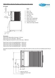
6. TECHNICAL DATA<br />
REFRIGERATED CABINET<br />
Model Storage Heat Ambient Ref Gas Capillary Electrica Amp Watts Extraction Evap Noise<br />
Ref Temp Output temp °C Gas charge size 1 Supply s (W) Rate Temp Level<br />
(W) standard grams (Standard) (A) (W) °C dBA<br />
GRL 1H 1 to 4 1290 43°C R404a 550 2.5mm x 054 230-50-1 2.8 510 620 -8 62<br />
GRL 1HP 1 to 4 1290 43°C R404a 550 2.5mm x 054 230-50-1 2.8 510 620 -8 62<br />
GRL 2H 1 to 4 1650 43°C R404a 800 3.5mm x 064 230-50-1 3.7 750 880 -8 64<br />
GRL 2HP 1 to 4 1650 43°C R404a 800 3.5mm x 064 230-50-1 3.7 750 880 -8 64<br />
GRLF 1H 1 to 4 1290 43°C R404a 550 2.5mm x 054 230-50-1 2.8 510 620 -8 62<br />
GRL 1H/G 1 to 4 1290 43°C R404a 550 2.5mm x 054 230-50-1 2.8 510 620 -8 62<br />
GRL 2H/G 1 to 4 1650 43°C R404a 800 3.5mm x 064 230-50-1 3.7 750 880 -8 64<br />
GR 1H 1 to 4 620 43°C R134a 360 2.0mm x 042 230-50-1 2.3 305 346 -8 60<br />
GR 2H 1 to 4 1080 43°C R134a 400 3.0mm x 064 230-50-1 2.8 510 679 -8 64<br />
GR 1H/G 1 to 4 620 43°C R134a 360 3.0mm x 054 230-50-1 2.3 305 346 -8 60<br />
GR 2H/G 1 to 4 1080 43°C R134a 400 3.0mm x 064 230-50-1 2.8 510 679 -8 64<br />
HEATED CABINETS<br />
Model Ref Storage Ambient Humidity volts phase Hz Amps Watts Heat<br />
Temp temp °C RH (A) (W) output<br />
(W)<br />
GRL 1X 75 to 80 43°C 40% 230 1 50 13 3000 3000<br />
GR 1X 75 to 80 43°C 40% 230 1 50 4.4 1000 1000<br />
13
(see page 16 for general arrangement)<br />
7. ACCESS<br />
GRL 1H<br />
7.1 The Foster CDC controller is accessible from the front of the unit for all programm<strong>in</strong>g functions.<br />
IMPORTANT - all repairs must be carried out with the ma<strong>in</strong>s electrical supply disconnected and by a competent<br />
person.<br />
7.1.1 Access to electrical connections.<br />
To ga<strong>in</strong> access to the electrical connections you must firstly remove the unit cover, this is achieved by remov<strong>in</strong>g the two fix<strong>in</strong>g<br />
screws secur<strong>in</strong>g the cover to the side panels at the top and with a sharp forward motion pull the cover from the reta<strong>in</strong><strong>in</strong>g clips.<br />
Once removed the electrical box can be seen on the left hand side. Remove the front cover to ga<strong>in</strong> access to the electrical<br />
term<strong>in</strong>als.<br />
7.1.2 Controller replacement<br />
Remove the unit cover as described <strong>in</strong> 7.1.1. Unplug the ribbon cable from the electrical box and air probe from the controller.<br />
Release the two reta<strong>in</strong><strong>in</strong>g clips fitted to each side of the controller and slide the part forward through the cutout <strong>in</strong> the unit cover.<br />
Remove it from the cover. Reverse the procedure to fit the new controller. Programme the controller us<strong>in</strong>g the <strong>in</strong>formation<br />
stated <strong>in</strong> the sett<strong>in</strong>g up <strong>in</strong>structions. (see section 4).<br />
7.1.3 Temperature probe replacement<br />
Disconnect the probe from the controller. Unscrew the clips secur<strong>in</strong>g the probe cable to the cab<strong>in</strong>et. Remove the return airduct<br />
from the cab<strong>in</strong>et by remov<strong>in</strong>g the four fix<strong>in</strong>g screws (two each side). The probe is located <strong>in</strong> a clip opposite the evaporator<br />
fan. Release the probe from the clip and remove from the cab<strong>in</strong>et. For replacement reverse the procedure ensur<strong>in</strong>g the<br />
return airduct baffle is located correctly <strong>in</strong>to the grove at the rear of the dra<strong>in</strong> pan form<strong>in</strong>g a duct to stop short circuit<strong>in</strong>g of<br />
the airflow.<br />
7.1.4 Evaporator fan motor replacement<br />
Disconnect the fan wires from the term<strong>in</strong>al block. Unscrew the clips secur<strong>in</strong>g the fan cable to the cab<strong>in</strong>et. Remove the return<br />
airduct from the cab<strong>in</strong>et by remov<strong>in</strong>g the four fix<strong>in</strong>g screws (two each side). Slide the plastic dra<strong>in</strong> tube (located to the left-hand<br />
side of the fan) from the dra<strong>in</strong> pan/evaporator fan plate. Remove the two thumbscrews secur<strong>in</strong>g the dra<strong>in</strong> pan/fan plate to<br />
the evaporator. Gently ease it away from the evaporator allow<strong>in</strong>g the cables to be withdrawn also. Remove the four screws<br />
secur<strong>in</strong>g the fan to the hous<strong>in</strong>g to disengage the fan. To replace the fan reverse the procedure ensur<strong>in</strong>g the return air duct<br />
baffle is located correctly <strong>in</strong>to the grove at the rear of the dra<strong>in</strong> pan form<strong>in</strong>g a duct to stop short circuit<strong>in</strong>g of the airflow.<br />
7.1.5 Evaporator replacement<br />
Reclaim the refrigerant gas. Remove the return airduct and dra<strong>in</strong> pan/fan hous<strong>in</strong>g as described <strong>in</strong> 7.1.4 expos<strong>in</strong>g the evaporator.<br />
Once the refrigerant gas has been reclaimed from the system cut the suction pipe close to the compressor ensur<strong>in</strong>g enough<br />
pipe is left for reconnect<strong>in</strong>g. Unbraze the capillary from the 1 /4 tub<strong>in</strong>g exit<strong>in</strong>g the drier. Seal all refrigerant pipework with tape to<br />
avoid moisture <strong>in</strong>gress <strong>in</strong>to the system. Remove the four screws (two either side) secur<strong>in</strong>g the evaporator to the plug <strong>in</strong>terior.<br />
Carefully lower the evaporator from the plug box. Once removed unbraze the l<strong>in</strong>es from the evaporator and reconnect them<br />
to the replacement <strong>in</strong> the same way. Seal all refrigerant pipes with tape after braz<strong>in</strong>g prior to refitt<strong>in</strong>g the evaporator <strong>in</strong>to the<br />
plug box. It is good refrigeration practice to replace the drier when replac<strong>in</strong>g component parts <strong>in</strong> the refrigeration system.<br />
Remove the tape from the ends of the pipes and reconnect all the pipe work. Evacuate the system and charge with the<br />
correct amount of gas as shown <strong>in</strong> the technical data. Once the system has been regassed with refrigerant check for leaks.<br />
When completed replace the dra<strong>in</strong> pan/fan plate and refit the plastic dra<strong>in</strong> tube. Refit the air return duct ensur<strong>in</strong>g the baffle<br />
is located correctly <strong>in</strong>to the grove at the rear of the dra<strong>in</strong> pan form<strong>in</strong>g a duct to stop short circuit<strong>in</strong>g of the airflow.<br />
7.1.6 Compressor replacement<br />
14
Remove the unit cover as described <strong>in</strong> 7.1.1. To give more access the side panels can be removed by releas<strong>in</strong>g the four<br />
screws. Reclaim the refrigerant. Disconnect all electrical connections. On satisfactory reclamation of the refrigerant disconnect<br />
the pipework from the compressor and tape the ends of the pipes to avoid moisture <strong>in</strong>gress <strong>in</strong>to the system. It is important<br />
to note that the compressor manufacturers recommend that the replacement should be completed with<strong>in</strong> fifteen m<strong>in</strong>utes to<br />
avoid moisture <strong>in</strong>gress. With the pipes disconnected remove the four bolts secur<strong>in</strong>g the compressor to the base plate and<br />
remove it. Fit the anti-vibration rubber mounts to the compressor prior to re-<strong>in</strong>stallation ensur<strong>in</strong>g that the metal spacers are<br />
fitted correctly. Locate the bolts <strong>in</strong>to the threaded nutserts and tighten. Remove the tape from the ends of the pipes and<br />
reconnect the pipework. It is good practice to replace the drier when replac<strong>in</strong>g component parts <strong>in</strong> the refrigeration system.<br />
Evacuate the system and charge with the correct amount of refrigerant as shown <strong>in</strong> the technical data. Reconnect all electrical<br />
connections. Once the system has been recharged check for leaks. When completed replace all covers ensur<strong>in</strong>g they are<br />
all fitted correctly.<br />
7.1.7 Condenser fan replacement<br />
Remove the unit cover as described <strong>in</strong> 7.1.1. To give more access the side panels can be removed by releas<strong>in</strong>g the four<br />
screws. Disconnect the fan cables from the compressor term<strong>in</strong>al box located on the right hand side of the unit compartment.<br />
Remove the four screws secur<strong>in</strong>g the grid mount fan motor to the condenser. Reverse the procedure for replac<strong>in</strong>g the fan<br />
ensur<strong>in</strong>g that all screws and covers are fitted tightly and securely.<br />
7.1.8 Condenser replacement<br />
Remove the unit cover as described <strong>in</strong> 7.1.1. To give more access the side panels can be removed by releas<strong>in</strong>g the four<br />
screws. Reclaim the refrigerant gas. Remove the grid mount fan motor from the condenser. On satisfactory reclamation of<br />
the gas disconnect the pipework from the condenser and tape the ends of the pipes to avoid moisture <strong>in</strong>gress <strong>in</strong>to the system.<br />
It is important to note that the compressor manufacturers recommend that the change over should be completed with<strong>in</strong> fifteen<br />
m<strong>in</strong>utes to avoid moisture <strong>in</strong>gress. Once the pipes have been disconnected undo the screws secur<strong>in</strong>g the condenser to the<br />
base plate and remove it. Fit the replacement condenser. Remove the tape from the ends of the pipes and reconnect the<br />
pipework. It is good practice to replace the drier when replac<strong>in</strong>g component parts <strong>in</strong> the refrigeration system. Evacuate the<br />
system and charge with the correct amount of gas as shown <strong>in</strong> the technical data. Refit the fan. Once the system has been<br />
regassed check for leaks. When satisfied replace all covers ensur<strong>in</strong>g they are all fitted correctly.<br />
7.1.9 Complete refrigeration plug replacement<br />
Remove the unit cover as described <strong>in</strong> 7.1.1. To give more access the side panels can be removed by releas<strong>in</strong>g the four<br />
screws. Remove the air duct as described <strong>in</strong> 7.1.3. Remove the brackets located to the rear of the return air duct, these are<br />
secured by four screws <strong>in</strong> each. The front of the plug is secured externally. The plug is secured to the top of the cab<strong>in</strong>et,<br />
through the condens<strong>in</strong>g unit plate at the front by an 1 1 /4 x no 8 screw located under the drier. A strip of white foam tape is<br />
stuck to the top of the cab<strong>in</strong>et to provide a vapour seal. The complete plug can now be removed from the cab<strong>in</strong>et tak<strong>in</strong>g<br />
care not to damage the foam material. It is recommended that at least two people carry out this procedure. Reverse the<br />
procedure to fit the replacement tak<strong>in</strong>g care that the vapour seal is not damaged ensur<strong>in</strong>g that all screws and covers are<br />
fitted tightly and securely.<br />
15
General Arrangement<br />
GRL 1H<br />
16
(see page 19 for general arrangement)<br />
GRL 2H<br />
7.2 The Foster CDC controller is accessible from the front of the unit for all programm<strong>in</strong>g functions.<br />
IMPORTANT - all repairs must be carried out with the ma<strong>in</strong>s electrical supply disconnected and by a competent<br />
person.<br />
7.2.1 Access to electrical connections.<br />
To ga<strong>in</strong> access to the electrical connections remove the unit cover, this is achieved by remov<strong>in</strong>g the two fix<strong>in</strong>g screws secur<strong>in</strong>g<br />
the cover to the side panels at the top and the two screws located to the bottom edge of the cover located centrally to the<br />
doors, with a sharp forward motion pull the cover from the reta<strong>in</strong><strong>in</strong>g clips. Once removed the electrical box can be seen on<br />
the left hand side. Remove the front cover to ga<strong>in</strong> access to the electrical term<strong>in</strong>als.<br />
7.2.2 Controller replacement<br />
Remove the unit cover as described <strong>in</strong> 7.2.1. Unplug the ribbon cable from the electrical box and air probe from the controller.<br />
Release the two reta<strong>in</strong><strong>in</strong>g clips fitted to each side of the controller and slide the part forward through the cutout <strong>in</strong> the unit cover.<br />
Remove it from the cover. Reverse the procedure to fit the new controller. Programme the controller us<strong>in</strong>g the <strong>in</strong>formation<br />
stated <strong>in</strong> the sett<strong>in</strong>g up <strong>in</strong>structions. (see section 4).<br />
7.2.3 Temperature probe replacement<br />
Disconnect the probe from the controller. Unscrew the clips secur<strong>in</strong>g the probe cable to the cab<strong>in</strong>et. Remove the return<br />
airduct from the cab<strong>in</strong>et by remov<strong>in</strong>g the four fix<strong>in</strong>g screws (two each side). The probe is located <strong>in</strong> a clip centrally between<br />
the fans. Release the probe from the clip and remove from the cab<strong>in</strong>et. For replacement reverse the procedure ensur<strong>in</strong>g<br />
the return airduct baffle is located correctly <strong>in</strong>to the grove at the rear of the dra<strong>in</strong> pan form<strong>in</strong>g a duct to stop short circuit<strong>in</strong>g<br />
of the airflow.<br />
7.2.4 Evaporator fan motor replacement<br />
Disconnect the fan wires from the term<strong>in</strong>al block. Unscrew the clips secur<strong>in</strong>g the fan cable to the cab<strong>in</strong>et. Remove the return<br />
airduct from the cab<strong>in</strong>et by remov<strong>in</strong>g the four fix<strong>in</strong>g screws (two each side). Slide the plastic dra<strong>in</strong> tube (located to the righthand<br />
side of the fan) from the dra<strong>in</strong> pan/evaporator fan plate. Remove the two thumbscrews secur<strong>in</strong>g the dra<strong>in</strong> pan/fan plate<br />
to the evaporator. Gently ease it away from the evaporator allow<strong>in</strong>g the cables to be withdrawn also. Remove the four screws<br />
secur<strong>in</strong>g the fan to the hous<strong>in</strong>g to disengage the fan. To replace the fan reverse the procedure ensur<strong>in</strong>g the return air duct<br />
baffle is located correctly <strong>in</strong>to the grove at the rear of the dra<strong>in</strong> pan form<strong>in</strong>g a duct to stop short circuit<strong>in</strong>g of the airflow.<br />
7.2.5 Evaporator replacement<br />
Reclaim the refrigerant gas. Remove the return airduct and dra<strong>in</strong> pan/fan hous<strong>in</strong>g as described <strong>in</strong> 7.2.4 expos<strong>in</strong>g the evaporator.<br />
Once the refrigerant gas has been reclaimed from the system cut the suction pipe close to the compressor ensur<strong>in</strong>g enough<br />
pipe is left for reconnect<strong>in</strong>g. Unbraze the capillary from the 1 /4 tub<strong>in</strong>g exit<strong>in</strong>g the drier. Seal all refrigerant pipework with tape to<br />
avoid moisture <strong>in</strong>gress <strong>in</strong>to the system. Remove the four screws (two either side) secur<strong>in</strong>g the evaporator to the plug <strong>in</strong>terior.<br />
Carefully lower the evaporator from the plug box. Once removed unbraze the pipes from the evaporator and reconnect them<br />
to the replacement <strong>in</strong> the same way. Seal all refrigerant pipes with tape after braz<strong>in</strong>g prior to refitt<strong>in</strong>g the evaporator <strong>in</strong>to the<br />
plug box. It is good refrigeration practice to replace the drier when replac<strong>in</strong>g component parts <strong>in</strong> the refrigeration system.<br />
Remove the tape from the ends of the pipes and reconnect all the pipe work. Evacuate the system and charge with the<br />
correct amount of gas as shown <strong>in</strong> the technical data. Once the system has been recharged with refrigerant check for leaks.<br />
When completed replace the dra<strong>in</strong> pan/fan plate and refit the plastic dra<strong>in</strong> tube. Refit the air return duct ensur<strong>in</strong>g the baffle<br />
is located correctly <strong>in</strong>to the grove at the rear of the dra<strong>in</strong> pan form<strong>in</strong>g a duct to stop short circuit<strong>in</strong>g of the airflow.<br />
17
7.2.6 Compressor replacement<br />
Remove the unit cover as described <strong>in</strong> 7.2.1. To give more access the side panels can be removed by releas<strong>in</strong>g the four<br />
screws. Reclaim the refrigerant. Disconnect all electrical connections. On satisfactory reclamation of the refrigerant<br />
disconnect the pipework from the compressor and tape the ends of the pipes to avoid moisture <strong>in</strong>gress <strong>in</strong>to the system. It<br />
is important to note that the compressor manufacturers recommend that the replacement should be completed with<strong>in</strong> fifteen<br />
m<strong>in</strong>utes to avoid moisture <strong>in</strong>gress. With the pipes disconnected remove the four bolts secur<strong>in</strong>g the compressor to the base<br />
plate and remove it. Fit the anti-vibration rubber mounts to the compressor prior to re-<strong>in</strong>stallation ensur<strong>in</strong>g that the metal<br />
spacers are fitted correctly. Locate the bolts <strong>in</strong>to the threaded nutserts and tighten. Remove the tape from the ends of the<br />
pipes and reconnect the pipework. It is good refrigeration practice to replace the drier when replac<strong>in</strong>g component parts <strong>in</strong><br />
the refrigeration system. Evacuate the system and charge with the correct amount of gas as shown <strong>in</strong> the technical data.<br />
Reconnect all electrical connections. Once the system has been regassed check for leaks. When satisfied replace all covers<br />
ensur<strong>in</strong>g they are all fitted correctly.<br />
7.2.7 Condenser fan replacement<br />
Remove the unit cover as described <strong>in</strong> 7.2.1. To give more access the side panels can be removed by releas<strong>in</strong>g the four<br />
screws. Disconnect the fan cables from the compressor term<strong>in</strong>al box located on the right hand side of the unit compartment.<br />
Remove the four screws secur<strong>in</strong>g the grid mount fan motor to the condenser. Reverse the procedure for replac<strong>in</strong>g the fan<br />
ensur<strong>in</strong>g that all screws and covers are fitted tightly and securely.<br />
7.2.8 Condenser replacement<br />
Remove the unit cover as described <strong>in</strong> 7.2.1. To give more access the side panels can be removed by releas<strong>in</strong>g the four<br />
screws. Reclaim the refrigerant gas. Remove the grid mount fan motor from the condenser. On satisfactory reclamation of<br />
the gas disconnect the pipework from the condenser and tape the ends of the pipes to avoid moisture <strong>in</strong>gress <strong>in</strong>to the system.<br />
It is important to note that the compressor manufacturers recommend that the change over should be completed with<strong>in</strong> fifteen<br />
m<strong>in</strong>utes to avoid moisture <strong>in</strong>gress. Once the pipes have been disconnected undo the screws secur<strong>in</strong>g the condenser to the<br />
base plate and remove it. Fit the replacement condenser. Remove the tape from the ends of the pipes and reconnect the<br />
pipework. It is good practice to replace the drier when replac<strong>in</strong>g component parts <strong>in</strong> the refrigeration system. Evacuate the<br />
system and charge with the correct amount of gas as shown <strong>in</strong> the technical data. Refit the fan. Once the system has been<br />
regassed check for leaks. When satisfied replace all covers ensur<strong>in</strong>g they are all fitted correctly.<br />
7.2.9 Complete refrigeration plug replacement<br />
Remove the unit cover as described <strong>in</strong> 7.2.1. To give more access the side panels can be removed by releas<strong>in</strong>g the four<br />
screws. Remove the air duct as described <strong>in</strong> 7.2.3. Remove the brackets located to the rear of the return air duct, secured<br />
by four screws <strong>in</strong> each. The front of the plug is secured externally. The plug is secured to the top of the cab<strong>in</strong>et, via an angle<br />
attached o the front edge of the plug box. A strip of white foam tape is stuck to the top of the cab<strong>in</strong>et to provide a vapour seal.<br />
The complete plug can now be removed from the cab<strong>in</strong>et tak<strong>in</strong>g care not to damage the foam material. It is recommended<br />
that at least three people carry out this procedure. Reverse the procedure to fit the replacement tak<strong>in</strong>g care that the vapour<br />
seal is not damaged ensur<strong>in</strong>g that all screws and covers are fitted tightly and securely.<br />
18
General Arrangement<br />
GRL 2H<br />
19
(see page 22 for general arrangement)<br />
GR 1H<br />
7.3 The Foster CDC controller is accessible from the front of the unit for all programm<strong>in</strong>g functions.<br />
IMPORTANT - all repairs must be carried out with the ma<strong>in</strong>s electrical supply disconnected and by a competent<br />
person.<br />
7.3.1 Access to electrical connections.<br />
To ga<strong>in</strong> access to the electrical connections remove the unit cover, with a sharp forward motion pull the cover from the<br />
reta<strong>in</strong><strong>in</strong>g clips. Once removed the electrical box can be seen on the left hand side. Remove the front cover to ga<strong>in</strong> access<br />
to the electrical term<strong>in</strong>als.<br />
7.3.2 Controller replacement<br />
Remove the unit cover as described <strong>in</strong> 7.3.1. Unplug the ribbon cable from the electrical box and air probe from the controller.<br />
Release the two reta<strong>in</strong><strong>in</strong>g clips fitted to each side of the controller and slide the part forward through the cutout <strong>in</strong> the unit cover.<br />
Remove it from the cover. Reverse the procedure to fit the new controller. Programme the controller us<strong>in</strong>g the <strong>in</strong>formation<br />
given <strong>in</strong> the sett<strong>in</strong>g up <strong>in</strong>structions. (see section 4).<br />
7.3.3 Temperature probe replacement<br />
Disconnect the probe from the controller. Unscrew the clips secur<strong>in</strong>g the probe cable to the cab<strong>in</strong>et. Remove the return airduct<br />
from the cab<strong>in</strong>et by remov<strong>in</strong>g the four fix<strong>in</strong>g screws (two each side). The probe is located <strong>in</strong> a clip opposite the evaporator<br />
fan. Release the probe from the clip and remove from the cab<strong>in</strong>et. For fitt<strong>in</strong>g the replacement reverse the procedure ensur<strong>in</strong>g<br />
the return airduct baffle is located correctly <strong>in</strong>to the grove at the rear of the dra<strong>in</strong> pan form<strong>in</strong>g a duct to stop short circuit<strong>in</strong>g<br />
of the airflow.<br />
7.3.4 Evaporator fan motor replacement<br />
Disconnect the fan wires from the term<strong>in</strong>al block. Unscrew the clips secur<strong>in</strong>g the fan cable to the cab<strong>in</strong>et. Remove the return<br />
airduct from the cab<strong>in</strong>et by remov<strong>in</strong>g the four fix<strong>in</strong>g screws (two each side). Slide the plastic dra<strong>in</strong> tube (located to the left-hand<br />
side of the fan) from the dra<strong>in</strong> pan/evaporator fan plate. Remove the two thumbscrews secur<strong>in</strong>g the dra<strong>in</strong> pan/fan plate to<br />
the evaporator. Gently ease it away from the evaporator allow<strong>in</strong>g the cables to be withdrawn also. Remove the four screws<br />
secur<strong>in</strong>g the fan to the hous<strong>in</strong>g to disengage the fan. To replace the fan reverse the procedure ensur<strong>in</strong>g the return air duct<br />
baffle is located correctly <strong>in</strong>to the grove at the rear of the dra<strong>in</strong> pan form<strong>in</strong>g a duct to stop short circuit<strong>in</strong>g of the airflow.<br />
7.3.5 Evaporator replacement<br />
Reclaim the refrigerant gas. Remove the return airduct and dra<strong>in</strong> pan/fan hous<strong>in</strong>g as described <strong>in</strong> 7.3.4 expos<strong>in</strong>g the evaporator.<br />
Once the refrigerant gas has been reclaimed from the system cut the suction pipe close to the compressor ensur<strong>in</strong>g enough<br />
pipe is left for reconnect<strong>in</strong>g. Unbraze the capillary from the 1 /4 tub<strong>in</strong>g exit<strong>in</strong>g the drier. Seal all refrigerant pipework with tape to<br />
avoid moisture <strong>in</strong>gress <strong>in</strong>to the system. Remove the four screws (two either side) secur<strong>in</strong>g the evaporator to the plug <strong>in</strong>terior.<br />
Carefully lower the evaporator from the plug box. Once removed unbraze the pipes from the evaporator and reconnect them<br />
to the replacement <strong>in</strong> the same way. Seal all refrigerant pipes with tape after braz<strong>in</strong>g prior to refitt<strong>in</strong>g the evaporator <strong>in</strong>to the<br />
plug box. It is good refrigeration practice to replace the drier when replac<strong>in</strong>g component parts <strong>in</strong> the refrigeration system.<br />
Remove the tape from the ends of the pipes and reconnect all the pipe work. Evacuate the system and charge with the<br />
correct amount of gas as shown <strong>in</strong> the technical data. Once the system has been regassed with refrigerant check for leaks.<br />
When completed replace the dra<strong>in</strong> pan/fan plate and refit the plastic dra<strong>in</strong> tube. Refit the air return duct ensur<strong>in</strong>g the baffle<br />
is located correctly <strong>in</strong>to the grove at the rear of the dra<strong>in</strong> pan form<strong>in</strong>g a duct to stop short circuit<strong>in</strong>g of the airflow.<br />
20
7.3.6 Compressor replacement<br />
Remove the unit cover as described <strong>in</strong> 7.3.1. To give more access the refrigeration plug system can be moved forward<br />
approximately 100mm. Remove the air return duct as described <strong>in</strong> 7.3.3. Remove the air return duct as described <strong>in</strong> 7.3.3.<br />
Remove the brackets located to the rear of the return air duct, by four screws <strong>in</strong> each. The front of the plug is secured<br />
externally. The plug is secured to the top of the cab<strong>in</strong>et, through the condens<strong>in</strong>g unit plate at the front by an 1 1 /4 x no 8 screw<br />
located under the drier. A strip of white foam tape is stuck to the top of the cab<strong>in</strong>et to provide a vapour seal. Tak<strong>in</strong>g care not<br />
to damage the white <strong>in</strong>seal slide the complete plug forward. Reclaim the refrigerant gas. Disconnect all electrical connections.<br />
On satisfactory reclamation of the refrigerant disconnect the pipework from the compressor and tape the ends of the pipes<br />
to avoid moisture <strong>in</strong>gress <strong>in</strong>to the system. It is important to note that the compressor manufacturers recommend that the<br />
replacement should be completed with<strong>in</strong> fifteen m<strong>in</strong>utes to avoid moisture <strong>in</strong>gress. With the pipes disconnected remove the<br />
four bolts secur<strong>in</strong>g the compressor to the base plate and remove it. Fit the anti vibration rubber mounts to the compressor prior<br />
to re-<strong>in</strong>stallation ensur<strong>in</strong>g that the metal spacers are fitted correctly. Locate the bolts <strong>in</strong>to the threaded nutserts and tighten.<br />
Remove the tape from the ends of the pipes and reconnect the pipework. It is good refrigeration practice to replace the drier<br />
when replac<strong>in</strong>g component parts <strong>in</strong> the refrigeration system. Evacuate the system and charge with the correct amount of<br />
refrigerant as shown <strong>in</strong> the technical data. Reconnect all electrical connections. Once the system has been recharged check<br />
for leaks. When completed reposition the plug and replace all covers ensur<strong>in</strong>g they are all fitted correctly.<br />
7.3.7 Condenser fan replacement<br />
Remove the unit cover as described <strong>in</strong> 7.3.1. Disconnect the fan cables from the compressor term<strong>in</strong>al box located at the front<br />
of the compressor. Remove the four screws secur<strong>in</strong>g the grid mount fan motor to the condenser. Reverse the procedure for<br />
replac<strong>in</strong>g the fan ensur<strong>in</strong>g that all screws and covers are fitted tightly and securely.<br />
7.3.8 Condenser replacement<br />
Remove the unit cover as described <strong>in</strong> 7.3.1. Reclaim the refrigerant gas. Remove the grid mount fan motor from the<br />
condenser. On satisfactory reclamation of the gas disconnect the pipework from the condenser and tape the ends of the<br />
pipes to avoid moisture <strong>in</strong>gress <strong>in</strong>to the system. It is important to note that the compressor manufacturers recommend that the<br />
change over should be completed with<strong>in</strong> fifteen m<strong>in</strong>utes to avoid moisture <strong>in</strong>gress. Once the pipes have been disconnected<br />
undo the screws secur<strong>in</strong>g the condenser to the base plate and remove it. Fit the replacement condenser. Remove the tape<br />
from the ends of the pipes and reconnect the pipework. It is good refrigeration practice to replace the drier when replac<strong>in</strong>g<br />
component parts <strong>in</strong> the refrigeration system. Evacuate the system and charge with the correct amount of gas as shown <strong>in</strong><br />
the technical data. Refit the fan. Once the system has been regassed check for leaks. When satisfied replace all covers<br />
ensur<strong>in</strong>g they are all fitted correctly.<br />
7.3.9 Complete refrigeration plug replacement<br />
Remove the unit cover as described <strong>in</strong> 7.3.1. Remove the air duct as described <strong>in</strong> 7.3.3. Remove the brackets located to the<br />
rear of the return air duct, secured by four screws <strong>in</strong> each. The front of the plug is secured externally. The plug is secured to<br />
the top of the cab<strong>in</strong>et, through the condens<strong>in</strong>g unit plate at the front by an 1 1 /4 x no 8 screw located under the drier. A strip<br />
of white foam tape is stuck to the top of the cab<strong>in</strong>et to provide a vapour seal. The complete plug can now be removed from<br />
the cab<strong>in</strong>et tak<strong>in</strong>g care not to damage the foam material. It is recommended that at least two people carry out this procedure.<br />
Reverse the procedure to fit the replacement tak<strong>in</strong>g care that the vapour seal is not damaged ensur<strong>in</strong>g that all screws and<br />
covers are fitted tightly and securely.<br />
21
General Arrangement<br />
GR 1H<br />
22
(see page 25 for general arrangement)<br />
GR 2H<br />
7.4 The Foster CDC controller is accessible from the front of the unit for all programm<strong>in</strong>g functions.<br />
IMPORTANT - all repairs must be carried out with the ma<strong>in</strong>s electrical supply disconnected and by a competent<br />
person.<br />
7.4.1 Access to electrical connections.<br />
To ga<strong>in</strong> access to the electrical connections remove the unit cover, with a sharp forward motion pull the cover from the<br />
reta<strong>in</strong><strong>in</strong>g clips. Once removed the electrical box can be seen on the left hand side. Remove the front cover to ga<strong>in</strong> access<br />
to the electrical term<strong>in</strong>als.<br />
7.4.2 Controller replacement<br />
Remove the unit cover and electrical box cover as described <strong>in</strong> 7.4.1. Unplug the ribbon cable from the electrical box and<br />
air probe from the controller. Release the two reta<strong>in</strong><strong>in</strong>g clips fitted to each side of the controller and slide the part forward<br />
through the cutout <strong>in</strong> the unit cover. Remove it from the cover. Reverse the procedure to fit the new controller. Programme<br />
the controller us<strong>in</strong>g the <strong>in</strong>formation stated <strong>in</strong> the sett<strong>in</strong>g up <strong>in</strong>structions. (see section 4).<br />
7.4.3 Temperature probe replacement<br />
Disconnect the probe from the controller. Unscrew the clips secur<strong>in</strong>g the probe cable to the cab<strong>in</strong>et. Remove the rear airduct.<br />
Remove the return airduct from the cab<strong>in</strong>et by remov<strong>in</strong>g the four fix<strong>in</strong>g screws (two each side). The probe is located <strong>in</strong> a clip<br />
central to the evaporator fans. Release the probe from the clip and remove it from the cab<strong>in</strong>et. For replacement reverse the<br />
procedure ensur<strong>in</strong>g the return airduct baffle is located correctly <strong>in</strong>to the grove at the rear of the dra<strong>in</strong> pan form<strong>in</strong>g a duct to<br />
stop short circuit<strong>in</strong>g of the airflow.<br />
7.4.4 Evaporator fan motor replacement<br />
Disconnect the fan wires from the term<strong>in</strong>al block. Unscrew the clips secur<strong>in</strong>g the fan cable to the cab<strong>in</strong>et. Remove the rear<br />
airduct. Remove the return airduct from the cab<strong>in</strong>et by remov<strong>in</strong>g the four fix<strong>in</strong>g screws (two each side). Slide the plastic<br />
dra<strong>in</strong> tube (located to the right-hand side of the fans) from the dra<strong>in</strong> pan/evaporator fan plate. Remove the two thumbscrews<br />
secur<strong>in</strong>g the dra<strong>in</strong> pan/fan plate to the evaporator. Gently ease it away from the evaporator allow<strong>in</strong>g the cables to be withdrawn<br />
also. Remove the four screws secur<strong>in</strong>g the fan to the hous<strong>in</strong>g to disengage the fan. To replace the fan reverse the procedure<br />
ensur<strong>in</strong>g the return air duct baffle is located correctly <strong>in</strong>to the grove at the rear of the dra<strong>in</strong> pan form<strong>in</strong>g a duct to stop short<br />
circuit<strong>in</strong>g of the airflow.<br />
7.4.5 Evaporator replacement<br />
Reclaim the refrigerant gas. Proceed to remove the airduct and return airduct and dra<strong>in</strong> pan/fan hous<strong>in</strong>g as described <strong>in</strong><br />
7.4.4 expos<strong>in</strong>g the evaporator. Once the refrigerant gas has been reclaimed from the system cut the suction pipe close to the<br />
compressor ensur<strong>in</strong>g enough pipe is left for reconnect<strong>in</strong>g. Unbraze the capillary from the 1 /4 tub<strong>in</strong>g exit<strong>in</strong>g the drier. Seal all<br />
refrigerant pipework with tape to avoid moisture <strong>in</strong>gress <strong>in</strong>to the system. Remove the four screws (two either side) secur<strong>in</strong>g<br />
the evaporator to the plug <strong>in</strong>terior. Carefully lower the evaporator from the plug box. Once removed unbraze the l<strong>in</strong>es from<br />
the evaporator and connect them to the replacement <strong>in</strong> the same way. Seal all refrigerant pipes with tape after braz<strong>in</strong>g prior<br />
to refitt<strong>in</strong>g the evaporator <strong>in</strong>to the plug box. It is good refrigeration practice to replace the drier when replac<strong>in</strong>g component<br />
parts <strong>in</strong> the refrigeration system. Remove the tape from the ends of the pipes and reconnect all the pipe work. Evacuate the<br />
system and charge with the correct amount of gas as shown <strong>in</strong> the technical data. Once the system has been regassed with<br />
refrigerant check for leaks. When completed replace the dra<strong>in</strong> pan/fan plate and refit the plastic dra<strong>in</strong> tube. Refit the rear<br />
airduct and air return duct ensur<strong>in</strong>g the baffle is located correctly <strong>in</strong>to the grove at the rear of the dra<strong>in</strong> pan form<strong>in</strong>g a duct to<br />
stop short circuit<strong>in</strong>g of the airflow.<br />
23
7.4.6 Compressor replacement<br />
Remove the unit cover as described <strong>in</strong> 7.141. Reclaim the refrigerant gas. Disconnect all electrical connections. On satisfactory<br />
reclamation of the refrigerant disconnect the pipework from the compressor and tape the ends of the pipes to avoid moisture<br />
<strong>in</strong>gress <strong>in</strong>to the system. It is important to note that the compressor manufacturers recommend that the replacement should<br />
be completed with<strong>in</strong> fifteen m<strong>in</strong>utes to avoid moisture <strong>in</strong>gress. With the pipes disconnected undo the four bolts secur<strong>in</strong>g the<br />
compressor to the base plate and remove it. Fit the anti-vibration rubber mounts to the compressor prior to re-<strong>in</strong>stallation<br />
ensur<strong>in</strong>g that the metal spacers are fitted correctly. Locate the bolts <strong>in</strong>to the threaded nutserts and tighten. Remove the tape<br />
from the ends of the pipes and reconnect the pipework. It is good refrigeration practice to replace the drier when replac<strong>in</strong>g<br />
component parts <strong>in</strong> the refrigeration system. Evacuate the system and charge with the correct amount of refrigerant as shown<br />
<strong>in</strong> the technical data. Reconnect all electrical connections. Once the system has been recharged check for leaks. When<br />
completed reposition the plug and replace all covers ensur<strong>in</strong>g they are all fitted correctly.<br />
7.4.7 Condenser fan replacement<br />
Remove the unit cover as described <strong>in</strong> 7.4.1. Disconnect the fan cables from the compressor term<strong>in</strong>al box located at the front<br />
of the compressor. Remove the four screws secur<strong>in</strong>g the grid mount fan motor to the condenser. Reverse the procedure for<br />
replac<strong>in</strong>g the fan ensur<strong>in</strong>g that all screws and covers are fitted tightly and securely.<br />
7.4.8 Condenser replacement<br />
Remove the unit cover as described <strong>in</strong> 7.4.1. Reclaim the refrigerant gas. Remove the grid mount fan motor from the<br />
condenser. On satisfactory reclamation of the gas disconnect the pipework from the condenser and tape the ends of the<br />
pipes to avoid moisture <strong>in</strong>gress <strong>in</strong>to the system. It is important to note that the compressor manufacturers recommend that the<br />
change over should be completed with<strong>in</strong> fifteen m<strong>in</strong>utes to avoid moisture <strong>in</strong>gress. Once the pipes have been disconnected<br />
undo the screws secur<strong>in</strong>g the condenser to the base plate and remove it. Fit the replacement condenser. Remove the tape<br />
from the ends of the pipes and reconnect the pipework. It is good practice to replace the drier when replac<strong>in</strong>g component<br />
parts <strong>in</strong> the refrigeration system. Evacuate the system and charge with the correct amount of gas as shown <strong>in</strong> the technical<br />
data. Refit the fan. Once the system has been regassed check for leaks. When satisfied replace all covers ensur<strong>in</strong>g they<br />
are all fitted correctly.<br />
7.4.9 Complete refrigeration plug replacement<br />
Remove the unit cover as described <strong>in</strong> 7.4.1. Remove the rear and air return duct as described <strong>in</strong> 7.4.3. Remove the brackets<br />
located to the rear of the return air duct, secured by four screws <strong>in</strong> each. The front of the plug is secured externally. The<br />
plug is secured to the top of the cab<strong>in</strong>et, via an angle attached to the front edge of the plug box. A strip of foam tape is stuck<br />
to the top of the cab<strong>in</strong>et to provide a vapour seal. The complete plug can now be removed from the cab<strong>in</strong>et tak<strong>in</strong>g care not<br />
to damage the foam material. It is recommended that at least two people carry out this procedure. Reverse the procedure<br />
to fit the replacement tak<strong>in</strong>g care that the vapour seal is not damaged ensur<strong>in</strong>g that all screws and covers are fitted tightly<br />
and securely.<br />
24
General Arrangement<br />
GR 2H<br />
25
(see page 29 for general arrangement)<br />
GR 1X<br />
7.5 The MTR 122 controller is accessible from the front of the unit for all programm<strong>in</strong>g functions.<br />
IMPORTANT - all repairs must be carried out with the ma<strong>in</strong>s electrical supply disconnected and by a competent<br />
person.<br />
7.5.1 Access to electrical connections.<br />
To ga<strong>in</strong> access to the electrical connections remove the perforated panel at the top of the cab<strong>in</strong>et. This is achieved by<br />
remov<strong>in</strong>g the two screws secur<strong>in</strong>g the panel to the cab<strong>in</strong>et. Remove the rubber grommet from the panel and slide the ma<strong>in</strong>s<br />
cable through the slot allow<strong>in</strong>g the panel to be removed. For refitt<strong>in</strong>g reverse the procedure ensur<strong>in</strong>g the ma<strong>in</strong>s cable and<br />
grommet are fitted correctly. The electrical connections are located on the right-hand side viewed from the rear. Remove the<br />
four screws secur<strong>in</strong>g the lid to access the term<strong>in</strong>al block and overtemperature thermostat.<br />
7.5.2 Controller replacement<br />
Remove the unit cover and electrical box cover as described <strong>in</strong> 7.5.1. Disconnect the cables ensur<strong>in</strong>g that all cables are<br />
correctly identified for correct refitt<strong>in</strong>g. Release the two reta<strong>in</strong><strong>in</strong>g clips fitted to each side of the Controller and slide the<br />
part forward through the cutout <strong>in</strong> the unit cover. Remove it from the unit. Reverse the procedure to fit the new Controller.<br />
Programme the controller us<strong>in</strong>g the <strong>in</strong>formation given <strong>in</strong> the sett<strong>in</strong>g up <strong>in</strong>structions. (see section 4).<br />
7.5.3 Temperature probe replacement - see page 13 for detail<br />
Disconnect the probe from the controller. Unclip the probe wire from the top of the unit. Inside the unit at the top remove the<br />
fan hous<strong>in</strong>g by releas<strong>in</strong>g the three screws along the front edge. Release the airduct with a sharp forward motion releas<strong>in</strong>g<br />
the spr<strong>in</strong>g clips from their reta<strong>in</strong>ers and remove the duct. The sensor is fitted to the air deflector located between the fan and<br />
the heater. Remove it from its reta<strong>in</strong><strong>in</strong>g clip and withdraw it from the unit. Fit the replacement by revers<strong>in</strong>g the procedure<br />
ensur<strong>in</strong>g all covers are refitted correctly.<br />
7.5.4 Red overtemperature light illum<strong>in</strong>ated<br />
With the top perforated panel removed as described <strong>in</strong> 7.5.1 reset the thermostat by depress<strong>in</strong>g the green switch on the<br />
top right hand side above the temperature scale. If the unit starts immediately check if the fan is work<strong>in</strong>g, normally. If not<br />
disconnect the ma<strong>in</strong>s supply and check for free rotation of the fan motor and test the motor w<strong>in</strong>d<strong>in</strong>gs for open circuit condition.<br />
If satisfactory reconnect the electrical supply and check connections. If the fan is work<strong>in</strong>g check that the air ducts are not<br />
obstructed. If the overtemperature thermostat can not be reset it is possible it will need replac<strong>in</strong>g.<br />
7.5.5 Overtemperature thermostat replacement<br />
Remove the top perforated panel and cover as described <strong>in</strong> 7.5.1. Unscrew the two screws above and below the temperature<br />
scale attach<strong>in</strong>g the stat to its bracket. Unclip the thermostat capillary from the top of the unit. Inside the unit at the top remove<br />
the fan hous<strong>in</strong>g by releas<strong>in</strong>g the three screws along the front edge. Release the airduct with a sharp forward motion releas<strong>in</strong>g<br />
the spr<strong>in</strong>g clips from their reta<strong>in</strong>ers and remove the duct. The thermostat sensor is fitted to the air deflector plate located<br />
between the fan and the heater. Remove it from its reta<strong>in</strong><strong>in</strong>g clip and withdraw it from the unit. To fit a replacement reverse<br />
the procedure ensur<strong>in</strong>g that all covers are refitted correctly.<br />
7.5.6 Heater replacement<br />
Remove the rear airduct as described <strong>in</strong> 7.5.4. Remove the heater from its reta<strong>in</strong>ers. Fit the replacement heater to reta<strong>in</strong>er.<br />
If reconnection is be<strong>in</strong>g made close to the heater and not <strong>in</strong> the external term<strong>in</strong>al block ensure the correct connectors are<br />
used and that the jo<strong>in</strong>ts are sealed us<strong>in</strong>g a heat shr<strong>in</strong>k sleeve or an approved alternative.<br />
26
7.5.7 Fan motor replacement<br />
Remove the top perforated panel and cover as described <strong>in</strong> 7.5.1. The fan motor cover is located externally on the top of the<br />
cab<strong>in</strong>et. Remove the four screws secur<strong>in</strong>g the cover <strong>in</strong>to place. Remove the cover expos<strong>in</strong>g the fan motor and the electrical<br />
connections. Disconnect the cables. Proceed to the <strong>in</strong>side of the cab<strong>in</strong>et and remove the fan hous<strong>in</strong>g as described <strong>in</strong> 7.5.2.<br />
Unscrew the three screws hold<strong>in</strong>g the fan assembly <strong>in</strong> place and remove it from the hous<strong>in</strong>g. Refit, place the new assembly<br />
<strong>in</strong>to the hous<strong>in</strong>g ensur<strong>in</strong>g that the electrical connections are at the rear with the V shape po<strong>in</strong>t<strong>in</strong>g forward. Remake the<br />
electrical connections and replace all covers securely.<br />
(see page 30 for general arrangements)<br />
GRL 1X<br />
7.6 The MTR 122 controller is accessible from the front of the unit for all programm<strong>in</strong>g functions.<br />
IMPORTANT - all repairs must be carried out with the ma<strong>in</strong>s electrical supply disconnected and by a competent<br />
person.<br />
7.6.1 Access to electrical connections.<br />
To ga<strong>in</strong> access to the electrical connections remove the unit cover. This is achieved by releas<strong>in</strong>g the two fix<strong>in</strong>g screws<br />
secur<strong>in</strong>g the cover to the side panels at the top. With the screws removed exert a sharp forward motion to release the cover<br />
from the reta<strong>in</strong><strong>in</strong>g clips. On removal, the electrical box can be seen on the left-hand side. Remove the front cover to ga<strong>in</strong><br />
access to the electrical term<strong>in</strong>als.<br />
7.6.2 Controller replacement<br />
Remove the unit cover as described <strong>in</strong> 7.6.1. Disconnect the cables ensur<strong>in</strong>g that all cables are correctly identified for correct<br />
replacement. Release the two reta<strong>in</strong><strong>in</strong>g clips fitted to each side of the Controller and slide the part forward through the cutout<br />
<strong>in</strong> the unit cover. Remove it from the unit. Reverse the procedure to fit the new Controller. Programme the controller us<strong>in</strong>g<br />
the <strong>in</strong>formation given <strong>in</strong> the sett<strong>in</strong>g up <strong>in</strong>structions. (see section 4).<br />
7.6.3 Temperature probe replacement<br />
Disconnect the probe from the Controller. Unclip the probe wire from the top of the unit. Remove the vent/phial guard to<br />
expose the probe. Remove it from its reta<strong>in</strong><strong>in</strong>g clip and withdraw it from the unit. To fit a replacement reverse the procedure<br />
ensur<strong>in</strong>g that all covers are refitted correctly.<br />
7.6.4 Red overtemperature light illum<strong>in</strong>ated<br />
Access the electrical connections as described <strong>in</strong> 7.6.1. Reset the thermostat by depress<strong>in</strong>g the green switch on the top right<br />
hand side above the temperature scale. If the unit starts immediately check if the fan is work<strong>in</strong>g, normally. If not disconnect the<br />
ma<strong>in</strong>s supply and check for free rotation of the fan motor and test the motor w<strong>in</strong>d<strong>in</strong>gs for open circuit condition. If satisfactory<br />
reconnect the electrical supply and check connections. If the fan is work<strong>in</strong>g check that the air ducts are not obstructed. If<br />
the overtemperature thermostat can not be reset it is possible it will need replac<strong>in</strong>g.<br />
7.6.5 Cab<strong>in</strong>et overtemperature stat replacement<br />
Access the electrical connections as described <strong>in</strong> 7.6.1. Unscrew the two screws above and below the temperature scale<br />
attach<strong>in</strong>g the stat to its bracket. Remove the vent/phial guard to expose the probe. Remove it from its reta<strong>in</strong><strong>in</strong>g clip and<br />
withdraw it from the unit. To refit a replacement reverse the procedure ensur<strong>in</strong>g that all covers are refitted correctly.<br />
27
7.6.6 Heater assembly replacement<br />
Remove the <strong>in</strong>sulated metal cage cover<strong>in</strong>g the heater assembly. A “U” shaped cover at the fan end of the assembly and a<br />
clos<strong>in</strong>g plate at the opposite end, they are both screwed <strong>in</strong> position secur<strong>in</strong>g the assembly <strong>in</strong>to place. Remove the cage from<br />
the top tak<strong>in</strong>g care not to damage the <strong>in</strong>sulation. Disconnect the electrical cables. Release the four fix<strong>in</strong>g screws attach<strong>in</strong>g<br />
the heater assembly to the top of the cab<strong>in</strong>et and remove it. To refit a replacement reverse the procedure mak<strong>in</strong>g sure that<br />
all covers are refitted correctly ensur<strong>in</strong>g that the <strong>in</strong>sulation <strong>in</strong> the metal cage is not damaged when refitt<strong>in</strong>g.<br />
7.6.7 Heater duct safety thermostat replacement<br />
Access the electrical connections and remove the <strong>in</strong>sulated metal cage cover<strong>in</strong>g the heater assembly as described <strong>in</strong> 7.6.6.<br />
release the two screws above and below the temperature scale attach<strong>in</strong>g the thermostat to its bracket. The thermostat<br />
stat phial is located centrally beneath the heater assembly attached to a bracket. Remove the phial from its clip. To refit a<br />
replacement reverse the procedure mak<strong>in</strong>g sure that all covers are refitted correctly ensur<strong>in</strong>g that the <strong>in</strong>sulation <strong>in</strong> the metal<br />
cage is not damaged when refitt<strong>in</strong>g.<br />
7.6.8 Fan motor replacement<br />
Remove the <strong>in</strong>sulated metal cage cover<strong>in</strong>g the heater assembly as described <strong>in</strong> 7.6.6. Release the four fix<strong>in</strong>g screws<br />
attach<strong>in</strong>g the heater assembly to the top of the cab<strong>in</strong>et and remove it. Disconnect the fan wires. The fan motors is attached<br />
to the heater duct by four screws and nuts, remove the screws to separate the two parts. To refit a replacement reverse the<br />
procedure mak<strong>in</strong>g sure that all covers are refitted correctly ensur<strong>in</strong>g that the <strong>in</strong>sulation <strong>in</strong> the metal cage is not damaged<br />
when refitt<strong>in</strong>g.<br />
7.6.9 Heater replacement<br />
Remove the <strong>in</strong>sulated metal cage cover<strong>in</strong>g the heater assembly as described <strong>in</strong> 7.6.6. Release the four fix<strong>in</strong>g screws attach<strong>in</strong>g<br />
the heater assembly to the top of the cab<strong>in</strong>et and remove it. The heater duct is attached to the fan motor by four screws<br />
and nuts, remove the screws to separate the two parts. Unbolt the cables from the heater term<strong>in</strong>als. Release the two nuts<br />
secur<strong>in</strong>g the heater to the duct and extract it. To refit a replacement reverse the procedure mak<strong>in</strong>g sure that all covers are<br />
refitted correctly ensur<strong>in</strong>g that the <strong>in</strong>sulation <strong>in</strong> the metal cage is not damaged when refitt<strong>in</strong>g.<br />
28
General Arrangement<br />
HEATER FAN AND HEATER ROD ASSEMBLEY - GR 1X<br />
29
General Arrangement<br />
HEATER DETAIL - GRL 1X<br />
30
WIRING DIAGRAM<br />
31
WIRING DIAGRAM<br />
32
WIRING DIAGRAM<br />
33
No. Item Description Part Number GRL 1H<br />
1 Unit Compartment Side Panel 00-744789 2<br />
2 Vaporiser Tray Plastic F15271004 1<br />
3 Hot Gas Vap Coil Copper F16012000 1<br />
4 Unit Cover GRL1H ML-120049 1<br />
NI Unit Cover GRL1H/G Glass Door Option ML-120052 1<br />
5 Control Panel S<strong>in</strong>gle Switch Option F15680260 1<br />
NI Control Panel GRL 1H/G Double Switch Option F15680261 1<br />
6 On/Off Switch Green F15243565 1<br />
7 FDC 121 Controller Complete High Temperature Controller Kit F15246141 1<br />
NI FDC 121 Display and Ribb<strong>in</strong> Cable F15246142 1<br />
NI FDC 121 Power Unit F15246143 1<br />
NI FDC 121 Air/Coil Probes F15246144 2<br />
8 Door Complete with Bumper Bar Standard Right Hand ML-120053 1<br />
NI Door Complete with Bumper Bar Standard Left Hand ML-120054 1<br />
NI Glass Door Complete Standard Right Hand ML-120056 1<br />
NI Glass Door Complete Standard Left Hand ML-120057 1<br />
9 Door Lock Gast 2000 F15230366 1<br />
10 Door Gasket Black F15211751 1<br />
11 Wiper Gasket Assembly 304 Sta<strong>in</strong>less Steel ML-120058 1<br />
NI Wiper Gasket Reta<strong>in</strong>er F15711052 1<br />
12 Wiper Gasket Kit Rubber 00-554211 1<br />
13 Ramp 304 Sta<strong>in</strong>less Steel ML-120059 1<br />
14 Condenser No. 18 CCX F15431180 1<br />
15 Condenser Fan Motor R<strong>in</strong>g Mount F15470027 1<br />
16 Compressor R404A CAE 9460Z F15422049 1<br />
NI Compressor R22 CAE 9460T F15422048 1<br />
17 Drier R404A 1 /4” F15480908 1<br />
NI Drier R22 1 /4” F15480904 1<br />
NI Accumulator 3/8 Inlet 1 /2 Outlet F15480002 1<br />
NI Evaporator Lacquered Coil No. 42 F15463042 1<br />
NI Evaporator Fan R<strong>in</strong>g Mount 7 watt F15470015 1<br />
NI Evap Fan/Plate/Driptray Alum<strong>in</strong>ium F16020435 1<br />
18 Top baffle Duct Alum<strong>in</strong>ium F14207261 1<br />
NI Vap Tray Heater Mat 20 Watt 240 Volts F15240300 1<br />
NI Interior Light 1200mm 36 Watt F15244118 2<br />
NI Interior Light Control Gear Box Includ<strong>in</strong>g Ballast F15244118 1<br />
NI Interior Light Diffuser 1521mm cut to length F15244119 2<br />
NI Interior Light Switch Rocker F15243562 1<br />
NI Ref/Plugs System Complete GRL1H R404A ML-120079 1<br />
NI Ref/Plugs System Complete GRL1H/G R404A ML-120080 1<br />
NI Capillary R404A and R22 GRL1H/GRL1HG 2.5M x 054 1<br />
NI Gas Charge GRL1H/GRL1HG R404a 550grms R22 480 grms<br />
NI = NOT ILLUSTRATED<br />
9. ILLUSTRATED SPARE PARTS LIST<br />
GRL 1H<br />
34
General Arrangement<br />
GRL 1H<br />
35
GRL 2H<br />
No. Item Description Part Number GRL 2H<br />
1 Vaporiser Tray Plastic F15271004 1<br />
NI Hot Gas Vap Coil Copper F16012000 1<br />
NI Vap Tray Heater Mat 20 Watt 240 Volts F15240300 1<br />
2 Top Baffle Duct Alum<strong>in</strong>ium 00-745138 1<br />
3 Unit Compartment Side Panel 00-744789 2<br />
4 Condenser No. 18 CCX F15431180 1<br />
NI Condenser Fan Motor Grid Mount F15470027 1<br />
5 Compressor R404A CAE 9480Z F15422116 1<br />
NI Compressor R22 CAE 9480T F15422122 1<br />
6 Drier R404A 1 /4” F15480908 1<br />
NI Drier R22 1 /4” F15480904 1<br />
NI Accumulator 3/8 Inlet 1 /2 Outlet F15480002 1<br />
NI Evaporator Lacquered Coil No. 46 F15463046 1<br />
NI Evaporator Fan R<strong>in</strong>g Mount 7 Watt F15470015 2<br />
NI Evap Fan Plate/Driptray Alum<strong>in</strong>ium F16020482 1<br />
7 Unit Cover GRL2H ML-120055 1<br />
NI Unit Cover GRL2HG Glass Door Option ML-120060 1<br />
8 FDC 121 Controller Complete High Temperature Controller Kit F15246141 1<br />
NI FDC 121 Display and Ribbon Cable F15246142 1<br />
9 FDC 121 Power Unit F15246143 1<br />
NI FDC 121 Air/Coil Probes F15246144 2<br />
10 On/Off Switch Green F15243565 1<br />
11 Control Panel S<strong>in</strong>gle Switch Option F15680260 1<br />
NI Control Panel GRL1H/G Double Switch Option F15680261 1<br />
12 Door Complete with Bumper Bar Standard Right Hand ML-120053 1<br />
NI Door Complete with Bumper Bar Standard Left Hand ML-120054 1<br />
NI Glass Door Complete Standard Right Hand ML-120056 1<br />
NI Glass Door Complete Standard Left Hand ML-120057 1<br />
13 Door Lock Gast 2000 F15230366 2<br />
14 Door Gasket Black F15211751 2<br />
NI Wiper Gasket Reta<strong>in</strong>er F15711052 2<br />
15 Wiper Gasket Kit Rubber 00-554211 2<br />
16 Wiper Gasket Assembly 304 Sta<strong>in</strong>less Steel ML-120058 2<br />
17 Ramp 304 Sta<strong>in</strong>less Steel ML-120059 2<br />
NI Interior Light 1200mm 36 Watt F15244118 4<br />
NI Interior Light Control Gear Box Includ<strong>in</strong>g Ballast F15244118 2<br />
NI Interior Light Diffuser 1521mm cut to length F15244119 4<br />
NI Interior Light Switch Rocker F15243562 1<br />
NI Ref/Plugs System Complete R404A ML-120061 1<br />
NI Capillary R404A and R22 3.5M x 054 1<br />
NI Gas Charge R404A 800grms<br />
NI Gas Charge R22 575 grms<br />
NI = NOT ILLUSTRATED<br />
36
General Arrangement<br />
GRL 2H<br />
37
GR 1H<br />
No. Item Description Part Number GR 1H<br />
1 Compressor R134A AEZ 4430Y - GR1H F15422024 1<br />
NI Compressor R22 AEZ 4430E - GR1H F15422026 1<br />
NI Compressor R134A AEZ 444Y - GR1H/G Glass Door F15422044 1<br />
2 Condenser GR1H and GR1H/G No. 16BCX F15431160 1<br />
NI Condenser Fan Motor GR1H & R1H/G R<strong>in</strong>g Mount F15470026 1<br />
3 Drier R134A 1 /4” F15480908 1<br />
NI Drier R22 1 /4” F15480904 1<br />
NI Accumulator 9.6 x 9.6 x 30 x 175mm F15480001 1<br />
NI Evaporator Lacquered Coil No. 17 F15463017 1<br />
NI Evaporator Fan R<strong>in</strong>g Mount 7 Watt F15470031 1<br />
NI Evap Fan Plate/Driptray Alum<strong>in</strong>ium F16020435 1<br />
4 Unit Cover GR1H Standard ML-120062 1<br />
NI Unit Cover GR1H/G Glass Door Option ML-120063 1<br />
5 FDC 121 Controller Complete High Temperature Controller Kit F15246141 1<br />
NI FDC 121 Display and Ribbon Cable F15246142 1<br />
6 FDC 121 Power Unit F15246143 1<br />
NI FDC 121 Air/Coil Probes F15246144 2<br />
7 On/Off Switch Green F15243565 1<br />
8 Control Panel S<strong>in</strong>gle Switch Option F15680260 1<br />
NI Control Panel GRL1H/G Double Switch Option F15680261 1<br />
9 Top Baffle Duct Alum<strong>in</strong>ium 00-745041 1<br />
10 Vaporiser Tray Plastic F15271004 1<br />
11 Hot Gas Vap Coil Copper F16012000 1<br />
12 Door Complete with Bumper Bar Standard Right Hand ML-120064 1<br />
NI Door Complete with Bumper Bar Standard Left Hand ML-120065 1<br />
NI Glass Door Complete Standard Right Hand ML-120066 1<br />
NI Glass Door Complete Standard Left Hand ML-120067 1<br />
13 Door Lock Gast 2000 F15230366 1<br />
14 Door Gasket Black F15211731 1<br />
15 Wiper Gasket Assembly 304 Sta<strong>in</strong>less Steel ML-120068 1<br />
NI Wiper Gasket Reta<strong>in</strong>er F15711052 1<br />
16 Wiper Gasket Kit Rubber 00-554211 1<br />
17 Ramp 304 Sta<strong>in</strong>less Steel ML-120069 1<br />
NI Interior Light 1050mm 38 Watt F15244124 2<br />
NI Interior Light Control Gear Box Includ<strong>in</strong>g Ballast F15244122 1<br />
NI Interior Light Diffuser 1270mm Cut to Length F15244123 2<br />
NI Interior Light Switch Rocker F15243562 1<br />
NI Ref/Plugs System Complete GR1H R134A ML-120070 1<br />
NI Capillary R134A and R22 GR1H 3.0m x 042 1<br />
NI Gas Charge R134A GR1H 360 grms<br />
NI Gas Charge R22 GR1H 310 grms<br />
NI Ref/Plugs System Complete GR1H/G R134A ML-120071 1<br />
NI Capillary R134A GR1H/G 3.0m x 054 1<br />
NI Gas Charge R134A GR1H/G 360 grms<br />
NI = NOT ILLUSTRATED<br />
38
General Arrangement<br />
GR 1H<br />
39
GR 2H<br />
No. Item Description Part Number GR 2H<br />
1 Compressor R134A GR2H & GR2HG CAJ 4461 Y F15422062 1<br />
NI Compressor R22 GR2H & GR2HG CAE 9460T F15422048 1<br />
2 Condenser Fan Motor GR2H & GR2HG R<strong>in</strong>g Mount F15470027 1<br />
3 Condenser GR2H No. 16BCX F15431160 1<br />
NI Condenser GR2HG No. 18CCX F15431180 1<br />
NI Drier R134A 1 /4” F15480908 1<br />
NI Drier R22 1 /4” F15480904 1<br />
NI Accumulator 3/8 Inlet 1 /2 Outlet F15480002 1<br />
NI Evaporator Lacquered Coil No.31 F15463031 1<br />
NI Evaporator Fan R<strong>in</strong>g Mount 7 Watt F15470031 2<br />
NI Evap Fan Plate/Driptray Alum<strong>in</strong>ium F16020481 1<br />
NI Air Supply Duct White Plastic F15271050 1<br />
4 Unit Cover GR2H Standard ML-120072 1<br />
NI Unit Cover GR2H/G Glass Door Option ML-120073 1<br />
5 FDC 121 Controller Complete High Temperature Controller Kit F15246141 1<br />
NI FDC 121 Display and Ribbon Cable F15246142 1<br />
6 FDC 121 Power Unit F15246143 1<br />
NI FDC 121 Air/Coil Probes F15246144 1<br />
7 On/Off Switch Green F15243565 1<br />
8 Control Panel S<strong>in</strong>gle Switch Option F15680260 1<br />
NI Control Panel GRL1H/G Double Switch Option F15680261 1<br />
9 Top Baffle Duct Alum<strong>in</strong>ium F14200085 1<br />
10 Vaporiser Tray Plastic F15271005 1<br />
11 Hot Gas Vap Coil Copper F16012000 1<br />
12 Door Complete with Bumper Bar Standard Right Hand ML-120064 1<br />
NI Door Complete with Bumper Bar Standard Left Hand ML-120065 1<br />
NI Glass Door Complete Standard Right Hand ML-120066 1<br />
NI Glass Door Complete Standard Left Hand ML-120067 1<br />
13 Door Lock Gast 2000 F15230366 2<br />
14 Door Gasket Black F15211731 2<br />
15 Wiper Gasket Assembly 304 Sta<strong>in</strong>less Steel ML-120068 2<br />
NI Wiper Gasket Reta<strong>in</strong>er F15711052 2<br />
16 Wiper Gasket Kit Rubber 00-554211 2<br />
17 Ramp 304 Sta<strong>in</strong>less Steel ML-120069 2<br />
NI Interior Light 1050mm 38Watt F15244124 2<br />
NI Interior Light Control Gear Box Includ<strong>in</strong>g Ballast F15244122 1<br />
NI Interior Light Diffuser 1270mm Cut to Length F15244123 2<br />
NI Interior Light Switch Rocker F15243562 1<br />
NI Ref/Plugs System Complete GR2H R134A ML-120081 1<br />
NI Gas Charge R134A and Capillary GR2H 400 grms Capillary 3.0m x 064<br />
NI Gas Charge R22 and Capillary GR2H 310 grms Capillary 2.5m x 054<br />
NI Ref/plugs System Complete GR2H/G R134A ML120082 1<br />
NI Gas Charge R134A & Capillary GR2H/G 360 grms Capillary 3.0m x 064<br />
NI = NOT ILLUSTRATED<br />
40
General Arrangement<br />
GR 2H<br />
41
GR 1X<br />
No. Item Description Part Number GR 1X<br />
1 Heater Fan Top Cover Alum<strong>in</strong>ium 00-745146 1<br />
2 Temperature Stat Bracket Cover Alum<strong>in</strong>ium 00-7455393 1<br />
3 Temperature Stat Bracket 14200291 1<br />
4 Heater Fan Oven Fan 240/50 00-554022 1<br />
5 Heater Rod Spacer 00-745237 2<br />
6 Heater Rod 1000 W 00-554025 1<br />
7 Air Duct S/S 00-744936 2<br />
NI Safety Stat EMF 4U R3 F15452405 1<br />
NI Top Air Return Duct S/S 00-744936 1<br />
NI Digital Controller MTR 122 T1RES 00-554020 1<br />
NI Overtemperature Neon Red F15244680 1<br />
NI On/Off Switch Green F15243565 1<br />
NI Control Panel Recess With Double Switch Position F15680261 1<br />
NI Unit Cover ML-120047 1<br />
NI Unit Cover Endcap Top Left Bottom Right F15263027 2<br />
NI Unit Cover Endcap Top Right Bottom Left F15263026 2<br />
NI Door Right Hand Heated S/S ML-120074 1<br />
NI Door Left Hand S/S ML-120075 1<br />
NI Door Gasket F15211731 1<br />
NI Unit Compartment Cover 304 S/S 00-745007 1<br />
NI Ramp 304 Sta<strong>in</strong>less Steel ML-120059 1<br />
NI Wiper Gasket Assembly 304 Sta<strong>in</strong>less Steel ML-120058 1<br />
NI Wiper Gasket Kit Rubber 00-554211 1<br />
NI Wiper Gasket Reta<strong>in</strong>er F15711052 1<br />
NI = NOT ILLUSTRATED<br />
42
General Arrangement<br />
GR 1X<br />
43
GRL 1X<br />
No. Item Description Part Number GRL 1X<br />
1 Unit Compartment Side Panel 304 S/S 00-744789 2<br />
2 Unit Cover GRL1X 304 S/S ML-120049 1<br />
NI Unit Cover Endcap Top Left Bottom Right F15263027 2<br />
NI Unit Cover Endcap Top Right Bottom Left F15263026 2<br />
3 Duct Heater Assembly 3kw F15240050 1<br />
NI Duct Heater Assembly Motor Only F16240023 1<br />
NI Duct Heater Assembly Heater Only F16240040 1<br />
4 “U” Shaped Cover Alum<strong>in</strong>ium F14201381 1<br />
5 Vent/Phial Guard F14201378 1<br />
6 Insulated Cage F14201379 1<br />
7 Clos<strong>in</strong>g Plate Alum<strong>in</strong>ium F14102530 1<br />
8 Heater Duct Safety Stat EMF4U R3 F15452405 1<br />
9 Air Duct Throat Alum<strong>in</strong>ium F14201373 1<br />
10 Air Duct Alum<strong>in</strong>ium F14201372 1<br />
11 Right Hand Door Heated S/S ML-120076 1<br />
NI Left Hand Door Heated S/S ML-120077 1<br />
NI Door Gasket Black F15211751 1<br />
NI Wiper Gasket Reta<strong>in</strong>er F15711052 1<br />
NI Wiper Gasket Kit Rubber 00-554211 1<br />
NI Wiper Gasket Assembly 304 Sta<strong>in</strong>less Steel ML-120058 1<br />
NI Ramp 304 Sta<strong>in</strong>less Steel ML-120059 1<br />
NI Door Lock Gast 2000 F15230366 1<br />
NI Digital Controller MTR 122 T1RES 00-554020 1<br />
NI Overtemperature Neon Red F15244680 1<br />
NI On/Off Switch Green F15243565 1<br />
NI Control Panel Recess With Double Switch Position F15680261 1<br />
NI Door Switch C3006 BB F15243566 1<br />
NI 30 Amp Relay G7L-1A-T F15490420 1<br />
NI Relay Clip F15490421 1<br />
NI = NOT ILLUSTRATED<br />
44
General Arrangement<br />
GRL 1X<br />
45
PARTS COMMON TO ALL MODELS<br />
No. Item Description Part Number<br />
1 Lock Barrel Supra Cab<strong>in</strong>et Style F15230366<br />
2 Lock Bezel Black F15230369<br />
3 Key No. 92235 F15230364<br />
4 Lock Keep Supra Cab<strong>in</strong>et Style F15230367<br />
5 Keep Cover Supra Cab<strong>in</strong>et Style F15230368<br />
NI H<strong>in</strong>ge Barrel Top Ris<strong>in</strong>g F15230556<br />
NI H<strong>in</strong>ge Barrel Bottom Ris<strong>in</strong>g F15230555<br />
NI H<strong>in</strong>ge Bracket Top Right Bottom Left F15230518<br />
NI H<strong>in</strong>ge Bracket Top Left Bottom Right F15230519<br />
NI H<strong>in</strong>ge Bracket Reta<strong>in</strong><strong>in</strong>g Screw F15540014<br />
NI Ramp Thumb Screws M5 x 12mm F15560308<br />
NI = NOT ILLUSTRATED<br />
46
PARTS COMMON TO ALL MODELS<br />
47
General Arrangement<br />
48
Foster European Operations<br />
France<br />
Foster Refrigerator France SA<br />
Tel: 33 (01) 34 302222. Fax: 33 (01) 30 376874.<br />
Germany<br />
Foster Refrigerator GmbH<br />
Tel: 49 (202) 64870. Fax: 49 (202) 643044.<br />
Austria<br />
Foster Refrigerator Austria<br />
Tel: 43 (1) 815 1511. Fax: 43 (1) 813 2936.<br />
Spa<strong>in</strong>/Portugal<br />
Foster Refrigerator (Iberica)<br />
Tel: 34 (43) 463222. Fax: 34 (43) 463246.<br />
Holland<br />
Hobart Foster Holland BV<br />
Tel: 31 (348) 433 331. Fax: 31 (348) 430 117.<br />
Belgium<br />
Hobart Foster Belgium NV<br />
Tel: 32 (16) 606040. Fax: 32 (16) 605988.<br />
Denmark<br />
Hobart Foster Denmark A/S<br />
Tel: 45 (98) 141199. Fax: 45 (98) 141703.<br />
Norway<br />
Hobart Foster Norge A/S<br />
Tel: 47 (67) 533878. Fax: 47 (67) 536742.<br />
Sweden<br />
Hobart Foster Sverige AB<br />
Tel: 46 (0) 8 584 50 920. Fax: 46 (0) 8 584 50 929.<br />
PMI FEG Offices<br />
Asia/Pacific<br />
PMI Food Equipment Group (Hong Kong) Ltd.<br />
Tel: (852) 3419315. Fax: (852) 3413914.<br />
Middle East<br />
PMI Food Equipment Group (Dubai).<br />
Tel: 971 (4) 497393. Fax: 971 (4) 448232.<br />
Japan<br />
PMI Food Equipment Group (Japan) Inc.<br />
Tel: 81 (3) 37443511. Fax: 81 (3) 37444011.<br />
Malaysia<br />
PMI Food Equipment Group (Malaysia) Inc.<br />
Tel: 603 780 6779. Fax: 603 781 4535.<br />
S<strong>in</strong>gapore<br />
PMI Food Equipment Group (S<strong>in</strong>gapore) Inc.<br />
Tel: 65 665 0487. Fax: 65 665 0487.<br />
Foster Refrigerator Group of Companies,<br />
Oldmedow Road, K<strong>in</strong>g’s Lynn,<br />
Norfolk PE30 4JU<br />
England<br />
Tel: 01553 691122<br />
Fax: 01553 691447<br />
GASTROLL/SM/10/99 S<br />
e r v i c e M a n u a l