Cypress Duprex
Cypress Duprex
Cypress Duprex

You also want an ePaper? Increase the reach of your titles
YUMPU automatically turns print PDFs into web optimized ePapers that Google loves.
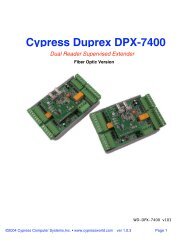
<strong>Cypress</strong> <strong>Duprex</strong><br />
Dual Reader Supervised Extender<br />
Wiring Diagram and Operators Manual<br />
MAN-FA-DPX-7000 V1.07<br />
©2005 <strong>Cypress</strong> Computer Systems,Inc. • www.cypressworld.com 11/21/05 Page 1
Table of Contents<br />
Quick Reference guides Page 3<br />
General specifications, Dip switch settings Page 5<br />
Electrical specifications, Introduction Page 6<br />
Status indicators and Dip switch details Page 7<br />
Identification of major components Page 8<br />
Detailed terminal connections Page 9<br />
Power connection Page 11<br />
Communication connections Page 14<br />
Reader data connections Page 15<br />
Door strike relay Page 18<br />
Alternate I/O SW #5 ON, Strike and Alarm Relays Page 19,20<br />
Auxiliary inputs and outputs Page 21<br />
Supervised contacts and programming resistors Page 25 - 28<br />
Part numbers for different versions:<br />
DPX-7000: RS-485 Twisted pair<br />
DPX-7500: RS-232 wired<br />
DPX-5000 Series *: <strong>Duprex</strong> RF 900 MHz<br />
DPX-5100 Series *: <strong>Duprex</strong> RF, 900 MHz, extended temperature range<br />
DPX-5200 Series *: <strong>Duprex</strong> RF, 2.4 GHz<br />
DPX-7200 Series *: <strong>Duprex</strong> Ethernet<br />
DPX-7400 Series *: <strong>Duprex</strong> Fiber Optic<br />
* supplemental installation manuals available<br />
©2005 <strong>Cypress</strong> Computer Systems,Inc. • www.cypressworld.com 11/21/05 Page 2
Connector Terminal Identification- Quick Reference<br />
Panel /Port # 1 Signals<br />
Alarm Programming Resistor<br />
Aux #3 Programming Resistor<br />
Aux Digital I/O #1 Input<br />
Aux Digital I/O #2 Output<br />
Aux Digital I/O #3 Output<br />
Alarm Relay N.O.<br />
Alarm Relay Com<br />
Alarm Relay N.C.<br />
LED<br />
Data 1 /Data<br />
Data 0 /Clock<br />
+5 VDC<br />
Ground<br />
+8 - 24 VDC<br />
Reader # 1 Signals<br />
Alarm Digital Input<br />
Aux Digital I/O #3 Input<br />
Aux Digital I/O #1 Output<br />
Aux Digital I/O #2 Input<br />
N/C<br />
Strike Relay N.O<br />
Strike Relay Com<br />
Strike Relay N.C.<br />
LED<br />
Data 1 /Data<br />
Data 0 /Clock<br />
+5 VDC<br />
Ground<br />
+8 - 24 VDC<br />
Line -<br />
Line +<br />
Line -<br />
Line +<br />
+8 - 24 VDC<br />
+8 - 24 VDC<br />
Reader # 2 Signals<br />
Strike Relay N.C.<br />
Strike Relay Com<br />
Strike Relay N.O.<br />
N/C<br />
Aux Digital I/O #2 Input<br />
Aux Digital I/O #1 Output<br />
Aux Digital I/O #3 Input<br />
Alarm Digital Input<br />
©2005 <strong>Cypress</strong> Computer Systems,Inc. • www.cypressworld.com 11/21/05 Page 3<br />
Gnd<br />
C<br />
<strong>Duprex</strong> Central Unit<br />
Gnd<br />
R<br />
<strong>Duprex</strong> Remote Unit<br />
Panel/Port # 2 Signals<br />
+8 - 24 VDC<br />
Ground<br />
+5 VDC<br />
Data 0 /Clock<br />
Data 1 /Data<br />
LED<br />
Alarm Relay N.C<br />
Alarm Relay Com<br />
Alarm Relay N.O<br />
Aux Digital I/O #3 Output<br />
Aux Digital I/O #2 Output<br />
Aux Digital I/O #1 Input<br />
Aux #3 Programming Resistor<br />
Alarm Programming Resistor<br />
+8 - 24 VDC<br />
Ground<br />
+5 VDC<br />
Data 0 /Clock<br />
Data 1 /Data<br />
LED
1 2 3 4 5 6 7 8<br />
DIP Switch Settings- Quick Reference<br />
NOT USED<br />
ALL OFF<br />
On<br />
Off<br />
Wiegand<br />
Wiegand / No Filter<br />
Strobed Rising Edge (MR-5)<br />
Strobed Rising Edge (Dorado 644)<br />
Strobed Rising (Mag-Tek)<br />
Strobed Falling Edge<br />
Reserved<br />
Reserved<br />
1 2 3 4 5 6 7 8<br />
Switch<br />
6 7 8<br />
0<br />
1 x<br />
2 x<br />
3 x x<br />
4 x<br />
5 x x<br />
6 x x<br />
7 x x x<br />
x = ON<br />
CENTRAL UNIT ONLY<br />
Dip switch #5 is ON<br />
Alternate I/O Assignment<br />
a. Door Strike relay does NOT follow LED<br />
(Auxiliary setting, will follow Digital Input #1)<br />
b. Alarm Relay and Digital Output #3 swap<br />
functions.<br />
All settings except Switch 5 are the same for Central and Remote units.<br />
©2005 <strong>Cypress</strong> Computer Systems,Inc. • www.cypressworld.com 11/21/05 Page 4
General Description and specifications:<br />
The <strong>Cypress</strong> <strong>Duprex</strong> series DPX-7000 is the latest addition to the Suprex line of products.<br />
For those familiar with the <strong>Cypress</strong> Suprex series, a DPX-7000 can be considered as 2, SPX-2000<br />
units in one package that share the same communication channel.<br />
The DPX-7000 will connect up to 2 readers to 2 panels using 1 pair of wires. There is also the ability to<br />
send additional signals such as Request to Exit, Tamper, Alarm, and Door contacts with each reader<br />
port.<br />
A DPX-7000 system consists of a pair of units. A Central unit connects to the Access Control Panel and<br />
a Remote unit connects to the Badge reader and door/ gate hardware. The reader data and status<br />
signals are sent over a single pair of wires up to 10,000 feet . Modules are available for Radio (RF),<br />
Fiber optic, and Ethernet data links.<br />
The DPX-7000 series has the ability to be field configured for various reader formats.<br />
The DPX-7000 series has also eliminated the need for “Pullup” resistors in most installations.<br />
Suprex Remote Unit Dip Switch Settings<br />
All Off except 6,7,8 (see below for details)<br />
Suprex Central Unit Dip Switch Settings<br />
Switch #5- On = Alternate I/O Assignment:<br />
Strike relay does NOT follow LED , will follow Digital Input #1<br />
Alarm relay and Digital Output #3 exchange functions.<br />
Off = (Default) Normal operation. Strike follows LED status.<br />
Dip Switch Settings 6.7.8 for Central AND Remote<br />
Switches 6,7,8 select the type of reader format used.<br />
Mode 0. 6,7,8 OFF = Standard Wiegand<br />
Mode 1. 6,7 OFF ; 8 ON = Wiegand without filtering<br />
Mode 2. 6 OFF, 7 ON, 8 OFF = Strobed, rising edge trigger, (MR-5® Compatible)<br />
Mode 3. 6 OFF, 7 ON, 8 ON = Strobed, rising edge trigger, (Dorado 644® compatible)<br />
Mode 4. 6 ON, 7 OFF, 8 OFF = Strobed,rising edge trigger, (Mag-Tek® compatible)<br />
Mode 5 6 ON, 7 OFF, 8 ON = Strobed, falling edge trigger<br />
©2005 <strong>Cypress</strong> Computer Systems,Inc. • www.cypressworld.com 11/21/05 Page 5
Specifications:<br />
Voltage- 8 to 24 VDC OR + 5VDC<br />
Current- 100 mA nominal<br />
Range: Up to 10,000 feet for RS-485 versions<br />
May vary due to quality of wiring. Any isolated wire pair will function<br />
with possible degraded performance.<br />
Optimal wiring is shielded twisted pair of 22 ga. or better.<br />
Relay Contact Rating- 2A @ 125 VAC<br />
Digital Input Rating: 0 to + 5 Volts DC standard CMOS logic levels<br />
Digital Output Rating: 25 mA Sink 0.5 mA source (10k pullup resistor)<br />
Initial Installation<br />
Before installing the units in the field, it is a good idea to connect and apply power to the units<br />
on a bench before installation in the field location. This is especially recommended if there is<br />
unfamiliarity with the Suprex/<strong>Duprex</strong> series of products. By initially connecting and powering up the<br />
units together, the operation can be observed on both the Central and Remote. Wiring configuration<br />
and connections can be verified, and any potential problems can be solved much easier than if the<br />
units are separated by several thousand feet.<br />
We recommend that the installation proceed in the following order:<br />
1. Unpackage the units and visually inspect for any shipping damage.<br />
2. Using a power supply or access control panel, apply power to both units using the same power<br />
configuration that will be utilized in the final installation.<br />
3. Connect communication lines RS485 (+) and RS485 ( -) between the Central and Remote.<br />
4. Check LED indicators for normal operation. With the communication lines connected, the yellow<br />
led should flash rapidly and the diagnostic led should flash on and off about once per second. The<br />
green power LED should be illuminated steady.<br />
5. Check/ Set the dip switch on Central and Remote units for the type of reader data format that will be<br />
used.<br />
6. If a reader and panel are available , connect the reader to the Remote unit and connect the Central<br />
unit to the panel. Using a test badge, verify that the panel can receive badge reads from the reader,<br />
and that the Strike / LED signals are operating in the expected manner.<br />
7. Install the units in their final locations.<br />
©2005 <strong>Cypress</strong> Computer Systems,Inc. • www.cypressworld.com 11/21/05 Page 6
Indicators:<br />
Each duprex unit is equipped with 3 leds to convey the operational status of the unit.<br />
Green power LED:<br />
This led will illuminate a continuous green color when power is applied to the unit. If this led is<br />
not illuminated, power has been lost to the unit.<br />
Amber communication LED:<br />
The communication LED indicates the actual communication activity between the Central and<br />
Remote unit. The LED will flash rapidly (about 5 times per second) when the Central and<br />
Remote units are communicating.<br />
When communication is lost the Amber LED will flash slower at about 1-2 times per second.<br />
BiColor diagnostic LED:<br />
This led will indicate basic status of the units. If the units are not in communication with each<br />
other the diagnostic LED will light a solid red color. When the units are able to communicate with<br />
each other, the diagnostic LED will flash green on and off about once per second.<br />
DIP Switch Settings:<br />
INDICATORS AND SETTINGS<br />
The <strong>Cypress</strong> <strong>Duprex</strong> supports multiple reader data formats. Each data format can be set with<br />
the dip switch. The dip switch format will be read each time the unit powers up.<br />
Mode 0 . Wiegand mode: Supports Wiegand data 24 to 248 bits. This mode will filter out data<br />
(noise) of less than 24 bits. This mode WILL allow keypad data of 4 and 8 bit burst mode<br />
Wiegand to pass.<br />
Mode 1. Wiegand mode without filter: This mode permits all Wiegand bits to be read without<br />
applying a noise filter. Any number of Wiegand bits from 4 to 248 will pass in this mode. Use<br />
this mode to support equipment that uses a nonstandard number of bits that number less than<br />
24 bits.<br />
Mode 2. Strobed data mode, Rising edge trigger. Mercury® MR-5 reader emulation.<br />
Mode 3. Strobed data mode, Rising edge trigger. Dorado® 644 reader emulation.<br />
Mode 4. Strobed data mode, Rising edge trigger. Mag-Tek® reader emulation<br />
Mode 5. Strobed data mode, Falling edge trigger. For all readers that trigger data on the falling<br />
clock edge.<br />
©2005 <strong>Cypress</strong> Computer Systems,Inc. • www.cypressworld.com 11/21/05 Page 7
The <strong>Cypress</strong> <strong>Duprex</strong> System consists of a Central and a Remote unit. Each <strong>Duprex</strong> board has<br />
connections for 2 reader channels. The Remote board has connections for 2 readers, the<br />
Central board has connections for 2 Panels or ports on multi reader panels.<br />
The Central and Remote are physically alike and will be identified by a sticker or permanent<br />
label with a large “C” or “Central” label and a large “R” or “Remote” label. Each reader/panel<br />
combination operates as a separate and independent channel.<br />
The reader connectors are identified by their relative location on the circuit board in relation to<br />
major components.<br />
Reader Number 1<br />
Signal connections<br />
to and from Panel<br />
Reader Number 1<br />
Data to Panel<br />
Reader Number 1<br />
Data from Reader<br />
{<br />
{<br />
Configuratio<br />
n<br />
Dip Switch<br />
{<br />
{<br />
Identification of major components<br />
©2005 <strong>Cypress</strong> Computer Systems,Inc. • www.cypressworld.com 11/21/05 Page 8<br />
C<br />
Central Unit<br />
Diagnostic LED (Red/Green/Yellow multi color)<br />
Reader Number 1<br />
Signal connections<br />
to and from access<br />
control devices.<br />
Strike Relays<br />
R<br />
Remote Unit<br />
Communication and<br />
power connector<br />
Alarm Relays<br />
{<br />
{<br />
Communication<br />
Activity LED<br />
(Amber)<br />
{<br />
{<br />
Reader Number 2<br />
Data to Panel<br />
Reader Number 2<br />
Signal connections<br />
to and from Panel<br />
Reader Number 2<br />
Data from Reader<br />
Reader Number 2<br />
Signal<br />
connections<br />
to and from<br />
access control<br />
devices.<br />
Power LED (Green)
Connector Terminal Identification- Central unit<br />
C<br />
Panel /Port # 1 Signals<br />
Alarm Programming Resistor<br />
Aux #3 Programming Resistor<br />
Aux Digital I/O #1 Input<br />
Aux Digital I/O #2 Output<br />
Aux Digital I/O #3 Output<br />
Alarm Relay N.O.<br />
Alarm Relay Com<br />
Alarm Relay N.C.<br />
LED<br />
Data 1 /Data<br />
Data 0 /Clock<br />
+5 VDC<br />
Ground<br />
+8 - 24 VDC<br />
Panel/Port # 2 Signals<br />
+8 - 24 VDC<br />
Ground<br />
+5 VDC<br />
Data 0 /Clock<br />
Data 1 /Data<br />
LED<br />
Alarm Relay N.C<br />
Alarm Relay Com<br />
Alarm Relay N.O<br />
Aux Digital I/O #3 Output<br />
Aux Digital I/O #2 Output<br />
Aux Digital I/O #1 Input<br />
Aux #3 Programming Resistor<br />
Alarm Programming Resistor<br />
C<br />
©2005 <strong>Cypress</strong> Computer Systems,Inc. • www.cypressworld.com 11/21/05 Page 9
Connector Terminal Identification- Remote unit<br />
R<br />
Reader # 1 Signals<br />
Alarm Digital Input<br />
Aux Digital I/O #3 Input<br />
Aux Digital I/O #1 Output<br />
Aux Digital I/O #2 Input<br />
N/C<br />
Strike Relay N.O<br />
Strike Relay Com<br />
Strike Relay N.C.<br />
LED<br />
Data 1 /Data<br />
Data 0 /Clock<br />
+5 VDC<br />
Ground<br />
+8 - 24 VDC<br />
Reader # 2 Signals<br />
+8 - 24 VDC<br />
Ground<br />
+5 VDC<br />
Data 0 /Clock<br />
Data 1 /Data<br />
LED<br />
Strike Relay N.C.<br />
Strike Relay Com<br />
Strike Relay N.O.<br />
N/C<br />
Aux Digital I/O #2 Input<br />
Aux Digital I/O #1 Output<br />
Aux Digital I/O #3 Input<br />
Alarm Digital Input<br />
R<br />
©2005 <strong>Cypress</strong> Computer Systems,Inc. • www.cypressworld.com 11/21/05 Page 10
Supplying Power:<br />
There are several ways to supply power to the <strong>Duprex</strong> units. Each of these will be<br />
discussed in detail.<br />
The 4 Wire method is used when there is only one power supply and the distance between the two<br />
units is not very large.<br />
A. The “4 Wire” method. This method uses one supply to power both the Central and<br />
Remote units. It requires 4 wires to connect the two units together. NOTE: The +8 to 24V connections<br />
on the reader interface connectors and the 4 position communication connector are electrically the<br />
same.<br />
The power supply can be located at either the Central or Remote unit. However, only one power<br />
supply should be used for this configuration. The power supply can be connected to the reader<br />
interface or the 4 position communication connector.<br />
Reader interface<br />
connector<br />
Gnd<br />
+V<br />
Line -<br />
Line +<br />
Communication Connector<br />
Power Supply<br />
+8 to 24 VDC<br />
Reader interface connector<br />
©2005 <strong>Cypress</strong> Computer Systems,Inc. • www.cypressworld.com 11/21/05 Page 11<br />
C<br />
R<br />
+V<br />
Gnd
Supplying Power:<br />
B. The “2 Wire” method. This method uses two power supplies. One to power the Central and the<br />
other to power the Remote unit. It requires 2 wires to connect the two units together. NOTE: The +8<br />
to 24V connections on the reader interface connectors and the 4 position communication connector<br />
are electrically the same.<br />
The power supplies are located at both the Central and Remote unit. The power supplies can be<br />
connected to either the reader interface or the 4 position communication connector. The illustration<br />
shows connection to reader interface connectors. Either the Reader 1 or Reader 2 connector can be<br />
used to connect the power supply.<br />
Warning: If connecting the <strong>Duprex</strong> Central unit to two separate panels or reader ports, do not supply<br />
power to the <strong>Duprex</strong> unit from more than ONE panel or one port. If using a panel to supply power,<br />
connect power from one panel and only connect the signal ground on the other panel. Connecting<br />
multiple power supplies can result in unpredictable operation or failure of the power supplies.<br />
Reader 1<br />
connector<br />
Line -<br />
Line +<br />
Power Supply<br />
+8 to 24 VDC<br />
Power Supply<br />
+8 to 24 VDC<br />
©2005 <strong>Cypress</strong> Computer Systems,Inc. • www.cypressworld.com 11/21/05 Page 12<br />
C<br />
R<br />
+V<br />
Gnd<br />
Reader 2<br />
connector
Supplying Power:<br />
C. The “2 Wire 5 Volt” method. This method also uses two supplies. One to power the Central and<br />
the other to power the Remote unit. It also requires 2 wires to connect the units together. This<br />
method is used when the only power available is an existing<br />
5 volt supply. It is not recommended to use one 5 volt supply to power both units.<br />
The power supplies are located at both the Central and Remote unit. The 5 volt power must be<br />
connected to the reader interface + 5 Volt and Ground connections. The other unit can be supplied<br />
by either a 5 volt or 8 to 24 volt supply.<br />
Note: When using the 5 Volt power connection, make sure that only one power supply is connected to<br />
each unit. The +8 to 24 and 5 Volt supplies should NEVER be connected or used at the same time.<br />
Illustration shows both units with 5 volt power supply.<br />
Reader 1<br />
connector<br />
Line -<br />
Line +<br />
C<br />
R<br />
Power Supply<br />
+5 VDC<br />
Reader 2<br />
connector<br />
Power Supply<br />
+5 VDC<br />
©2005 <strong>Cypress</strong> Computer Systems,Inc. • www.cypressworld.com 11/21/05 Page 13<br />
Gnd<br />
+5V<br />
Gnd<br />
+5V
Communication Connections and initial power application:<br />
The examples shown in the power connection methods also indicated how the RS-485<br />
communication lines are connected. Shown below is a typical connection for a <strong>Duprex</strong> Remote<br />
and Central unit using one of the power connection diagrams.<br />
With the units connected using A,B, or C power connections, turn on the power supply. Only power<br />
and communications connections should be made at this point.<br />
Data and I/O connections should be made after power and communication is verified.<br />
Regardless of which connection method is used, a correctly wired and operating setup will have<br />
these indications:<br />
a. The Green power indicator will be illuminated.<br />
b. The Amber communication indicators will be flashing rapidly on both Central and Remote units.<br />
c. The Diagnostic indicator will flash Green on and off at about once per second.<br />
Do not proceed further if this is not the case. Refer to the troubleshooting guide to correct any<br />
problems.<br />
Diagnostic<br />
indicators<br />
Gnd<br />
+V<br />
Line -<br />
Line +<br />
C<br />
Communication<br />
Active<br />
R<br />
Communication<br />
Active<br />
Power Supply<br />
+8 to 24 VDC<br />
Green Power<br />
indicator<br />
©2005 <strong>Cypress</strong> Computer Systems,Inc. • www.cypressworld.com 11/21/05 Page 14
Reader Data Connections:<br />
The diagrams below show data connections for the reader signals. Power and communication<br />
connections are still present, but have been removed from the diagram for clarity.<br />
A <strong>Duprex</strong> will support 2 reader data channels. The reader data channels operate separate and<br />
independent from each other. The <strong>Duprex</strong> can be wired with either reader port or both readers.<br />
It is important to remember that a reader on the Remote port 1 will output its data on the Central port 1<br />
and the Remote port 2 will output its data on the Central port 2. If no reader data is being observed at<br />
the panel, verify that the correct reader connections have been made and that the panel is connected to<br />
the correct port.<br />
Warning: If connecting the <strong>Duprex</strong> Central unit to two separate panels or reader ports, do not supply<br />
power to the <strong>Duprex</strong> unit from more than ONE panel or one port. If using a panel to supply power,<br />
connect power from one panel and only connect the signal ground on the other panel. Connecting<br />
multiple power supplies can result in unpredictable operation or failure of the power supplies.<br />
The DPX-7000 has eliminated the need for “Pullup” resistors in most installations.<br />
Control Panel<br />
Reader Port<br />
Number 1<br />
Card Reader<br />
Port Number 1<br />
Central<br />
Unit<br />
C<br />
R<br />
Remote<br />
Unit<br />
Control Panel<br />
Reader Port<br />
Number 2<br />
Card Reader<br />
Port Number 2<br />
©2005 <strong>Cypress</strong> Computer Systems,Inc. • www.cypressworld.com 11/21/05 Page 15
Detailed Reader Port Connections- Central unit<br />
Power supply connections are not shown for clarity.<br />
C<br />
Panel / Port # 1 Signals<br />
LED<br />
Data 1 /Data<br />
Data 0 /Clock<br />
Ground<br />
Panel / Port # 2 Signals<br />
Ground<br />
Data 0 /Clock<br />
Data 1 /Data<br />
LED<br />
C<br />
1 2 3 4 5 6 7 8<br />
©2005 <strong>Cypress</strong> Computer Systems,Inc. • www.cypressworld.com 11/21/05 Page 16
Detailed Reader Port Connections- Remote unit<br />
Power supply connections not shown to clarify data connections.<br />
R<br />
Reader # 1 Signals<br />
LED<br />
Data 1 /Data<br />
Data 0 /Clock<br />
+5 VDC<br />
Ground<br />
+ 8 to 24 VDC<br />
Reader # 2 Signals<br />
+ 8 to 24 VDC<br />
Ground<br />
+5 VDC<br />
Data 0 /Clock<br />
Data 1 /Data<br />
LED<br />
R<br />
1 2 3 4 5 6 7 8<br />
©2005 <strong>Cypress</strong> Computer Systems,Inc. • www.cypressworld.com 11/21/05 Page 17
Door Strike Relay connection and operation:<br />
In the standard configuration, the door strike relay on the Remote is activated when the LED<br />
signal is triggered on the Central unit. When the Central unit LED input is connected<br />
electrically to Ground ( 0 volt reference) it will trigger the LED output and Strike relay on the<br />
Remote unit.<br />
The dip switch on the Central unit can set two different modes for triggering the Door Strike.<br />
Interface #1LED<br />
signal from panel<br />
activates LED and<br />
Door Strike on<br />
Remote reader #1.<br />
Dip switch #5 is OFF<br />
Door Strike relay follows LED<br />
(Standard setting)<br />
1 2 3 4 5 6 7 8<br />
Door Strike Contacts<br />
Reader interface #1<br />
Door Strike Contacts Reader interface #2<br />
N.O. Contact<br />
Door Strike Contacts<br />
Common<br />
N.C. Contact<br />
N.C. Contact<br />
Common<br />
N.O. Contact<br />
Remote Unit<br />
©2005 <strong>Cypress</strong> Computer Systems,Inc. • www.cypressworld.com 11/21/05 Page 18<br />
C<br />
Central Unit<br />
R<br />
Interface #2LED<br />
signal from panel<br />
activates LED and<br />
Door Strike on<br />
Remote reader #1.
Door Strike Relay Alternate I/O Setting:<br />
In the Alternate I/O configuration, the door strike relay on the Remote is activated when the<br />
Auxiliary digital input signal is triggered on the Central unit. The Central unit LED input will only<br />
trigger the LED output on the Remote unit.<br />
When the auxiliary digital input #1 on the Central unit is activated (Grounded), the Door Strike<br />
Relay on the Remote unit will operate. This will operate in this manner as long as DIP switch #5 is<br />
set to ON at the Central unit.<br />
There is an auxiliary digital output on the Remote unit. This is a 0 to 5 volt digital output that<br />
always follows the Auxiliary digital input on the Central unit, regardless of the switch #5 setting. It<br />
can be used as an additional low power driver or I/O control. See Auxiliary inputs and outputs for<br />
details.<br />
Reader interface #1<br />
Auxiliary Digital I/O<br />
#1 Input<br />
triggers Strike Relay<br />
LED signal from panel<br />
only activates LED on<br />
Remote<br />
Reader interface #1<br />
Door Strike Contacts<br />
Auxiliary Digital output #1<br />
follows Aux input on<br />
Central<br />
N.O. Contact<br />
Common<br />
N.C. Contact<br />
1 2 3 4 5 6 7 8<br />
Dip switch #5 is ON<br />
Door Strike relay does NOT follow LED<br />
(Alternat I/O setting)<br />
Door Strike Contacts<br />
Remote Unit<br />
N.C. Contact<br />
Common<br />
N.O. Contact<br />
Auxiliary Digital output #1<br />
follows Aux input on<br />
Central<br />
©2005 <strong>Cypress</strong> Computer Systems,Inc. • www.cypressworld.com 11/21/05 Page 19<br />
C<br />
Central Unit<br />
R<br />
Reader interface #2<br />
LED signal from panel<br />
only activates LED on<br />
Remote<br />
Auxiliary Digital I/O #1<br />
Input triggers Strike<br />
Relay<br />
Reader interface #2<br />
Door Strike Contacts
Alarm Relay Alternate I/O Setting:<br />
In the Alternate I/O configuration, the Alarm relay on the Central is activated when the Auxiliary<br />
digital input signal is triggered on the Remote unit. The alarm function is re-assigned to Digital<br />
Output #3. In other words, The Alarm function and Digital Output #3 will swap places ON THE<br />
CENTRAL SIDE.<br />
This setting is used when a dry contact output needs to be sent from the Remote to the Central<br />
unit.<br />
Dip switch #5 is ON<br />
Alarm and Digital Output #3 Swap functions<br />
(Alternate I/O setting)<br />
Auxiliary Digital output #3<br />
Functions as Alarm Output<br />
1 2 3 4 5 6 7 8<br />
Panel Interface #1 Panel Interface #2<br />
N.O. Contact<br />
Common<br />
N.C. Contact<br />
Relay Contacts follow Aux<br />
Input #3 on Remote<br />
Central Unit<br />
N.C. Contact<br />
Common<br />
N.O. Contact<br />
©2005 <strong>Cypress</strong> Computer Systems,Inc. • www.cypressworld.com 11/21/05 Page 20<br />
C<br />
Relay Contacts follow Aux<br />
Input #3 on Remote<br />
Auxiliary Digital output #3<br />
Functions as Alarm Output
Auxiliary Inputs and Outputs:<br />
There are several additional low power I/O points that can be used on the <strong>Duprex</strong>-7000 series. These<br />
I/O points provide electrical signaling from the Central to the Remote and back from the Remote to the<br />
Central.<br />
Each output is a 0 - 5 volt digital logic signal level and can sink up to 25 mA. If additional power<br />
handling<br />
is required, an external relay or I/O module can be used.<br />
Each input also uses 0 - 5 volt digital logic signal levels. Each output will follow the status of its<br />
associated<br />
input. A signal change on Input #1 will be seen on Output #1, input 2 on output 2, input 3 on output 3.<br />
A logic low (0 volts) on the Alarm Digital Input will activate the Alarm relay on the Central unit.<br />
Relay contacts can be used with any voltage up to 120 VAC<br />
Auxiliary I/O uses 0 to +5 VOLT signals only<br />
Reader #1 Auxiliary I/O Connections<br />
Aux Digital I/O #1 Input<br />
Aux Digital I/O #2 Output<br />
Aux Digital I/O #3 Output<br />
Alarm Supervision Relay N.O.<br />
Alarm Supervision Relay Com<br />
Alarm Supervision Relay N.C.<br />
The Alarm supervision relay will close when both<br />
the Central and Remote units are powered up and<br />
communicating.<br />
Both Reader 1 and 2 relays will open if<br />
communication<br />
is lost.<br />
Alarm Digital Input<br />
Aux Digital I/O #3 Input<br />
Aux Digital I/O #1 Output<br />
Aux Digital I/O #2 Input<br />
C<br />
1 2 3 4 5 6 7 8<br />
R<br />
1 2 3 4 5 6 7 8<br />
©2005 <strong>Cypress</strong> Computer Systems,Inc. • www.cypressworld.com 11/21/05 Page 21
Auxiliary Inputs and Outputs<br />
Relay contacts can be used with any voltage to 120 VAC<br />
Auxiliary I/O uses 0 to +5 VOLT signals only<br />
C<br />
R<br />
Reader #2 Auxiliary I/O Connections<br />
Alarm Supervision Relay N.C.<br />
Alarm Supervision Relay Com<br />
Alarm Supervision Relay N.O.<br />
Aux Digital I/O #3 Output<br />
Aux Digital I/O #2 Output<br />
Aux Digital I/O #1 Input<br />
Aux Digital I/O #2 Input<br />
Aux Digital I/O #1 Output<br />
Aux Digital I/O #3 Input<br />
Alarm Digital Input<br />
©2005 <strong>Cypress</strong> Computer Systems,Inc. • www.cypressworld.com 11/21/05 Page 22
Using Auxiliary Inputs and Outputs: Digital Inputs<br />
Direct connections to the Auxiliary I/O operate at a maximum of +5 Volts. They can be used with<br />
most standard system control voltages using the techniques discussed below.<br />
The Digital I/O signals can interface directly to panels and readers that use 5 Volt signal levels. Each<br />
Digital I/O point is capable of sinking 25 mA of current. Application of voltages greater than 5 Volts<br />
can damage the board.<br />
The digital inputs are pulled up to +5 Volts and operate as active low, that is they will operate when<br />
connected to ground ( 0 Volts ). They can be driven by a digital output from a panel or reader, by an<br />
open collector output, or by a relay contact connected to ground.<br />
In no case should a Positive voltage greater than 5 Volts ever be applied to the digital inputs.<br />
Here are several examples of driving the <strong>Duprex</strong>-7000 series digital inputs using standard field<br />
wiring practices.<br />
Ground<br />
Activating a digital input with relay or switch contacts.<br />
Digital Input<br />
Ground<br />
Activating a digital input with open collector output device.<br />
Digital Input<br />
Open Collector Output<br />
©2005 <strong>Cypress</strong> Computer Systems,Inc. • www.cypressworld.com 11/21/05 Page 23
Using Auxiliary Inputs and Outputs: Digital Outputs<br />
The Digital Outputs also operate at 0 and +5 Volts. They are capable of sinking 25 mA and<br />
sourcing 0.5 mA. As digital signals, they can be interfaced directly to electronic equipment<br />
utilizing 5 Volt logic level signals such as panels and gate controllers. Check the manufacturers<br />
specifications for the equipment that you will interface to the <strong>Duprex</strong> to verify signal levels.<br />
Other external devices such as magnetic or solid state relays can be used if more drive<br />
capability is required.<br />
Activating an external relay with a digital output.<br />
Use a relay with a 5 volt coil and requiring less than 25<br />
mA<br />
drive current.<br />
+ 5 Volts from <strong>Duprex</strong><br />
K 1<br />
Digital Output<br />
Relay Contacts<br />
Activating a Solid State Relay. Use a relay with a 5<br />
volt input and requiring less than 25 mA drive current<br />
such as the Opto 22 or Crydom products using a logic<br />
level input.<br />
See relay manufacturers documentation for electrical<br />
and connection requirements.<br />
+ 5 Volts from <strong>Duprex</strong><br />
K 1<br />
Digital Output<br />
Solid State Relay Contacts<br />
©2005 <strong>Cypress</strong> Computer Systems,Inc. • www.cypressworld.com 11/21/05 Page 24<br />
K 1
Supervised contacts and programming resistors:<br />
One of the features of the <strong>Duprex</strong> is that it supports the use of supervised contacts. By setting<br />
programming resistors on the Central unit, the status of contacts and end of line resistors on the<br />
Remote unit can be monitored.<br />
Two of the inputs support supervised contacts. The Alarm and Digital I/O #3 can operate in<br />
supervised mode.<br />
Supervised mode uses the programming resistors on the Central unit to determine what value of end<br />
of line resistor it should sense on the Remote unit. If the value of the programming resistor and the<br />
end of line resistor is equal, the output is not activated. If they are not equal, the output is activated.<br />
End of line resistors from 1K (1000 ohms) to 20K (20,000 ohms) can be used. The resistor for the<br />
end of line should match the value of its associated programming resistor.<br />
C<br />
R<br />
Ground<br />
Digital I/O<br />
programming<br />
resistor<br />
Ground<br />
Alarm<br />
programming<br />
resistor<br />
Digital I/O #3 Alarm<br />
Contact and end Contact and end<br />
of line resistor of line resistor<br />
©2005 <strong>Cypress</strong> Computer Systems,Inc. • www.cypressworld.com 11/21/05 Page 25
Supervised mode for Digital I/O #3 will operate in the same<br />
manner as the Alarm input shown below, except the Digital<br />
Output #3 will be activated on Central unit.<br />
R<br />
R<br />
Ground<br />
Ground<br />
Digital I/O #3<br />
Contact and<br />
end<br />
of line resistor<br />
Digital I/O #3<br />
Contact and<br />
end<br />
of line resistor<br />
Alarm<br />
Contact and<br />
end<br />
of line resistor<br />
Alarm contact closure<br />
changes end of line<br />
value, Alarm relay<br />
will be activated on<br />
Central unit.<br />
Line broken changes<br />
end of line resistance<br />
value. Alarm relay<br />
will be activated on<br />
Central unit.<br />
Alarm<br />
Contact and<br />
end<br />
of line resistor<br />
©2005 <strong>Cypress</strong> Computer Systems,Inc. • www.cypressworld.com 11/21/05 Page 26
Application of supervised contacts - End of Line Resistors<br />
Some Access Control Panels utilize “End of Line Resistors” (EOL) to monitor the status of the wiring<br />
to the contact point. The <strong>Duprex</strong> system can be configured to support these types of circuits.<br />
The <strong>Duprex</strong> system can be configured to allow the Access Control Panel to monitor the End of Line<br />
Resistor. Resistors from 1k to 20k can be used.<br />
Panel Terminals<br />
Typical Panel with End of Line Resistor circuit<br />
Contact switch<br />
with EOL<br />
©2005 <strong>Cypress</strong> Computer Systems,Inc. • www.cypressworld.com 11/21/05 Page 27
Application of supervised contacts - End of Line Resistors<br />
In this application, 3 resistors are used. The EOL resistor at the Remote contact,<br />
the programming resistor on the Central unit, and a resistor accross the contacts of<br />
the relay on the Central unit. All 3 resistors should have the same value<br />
C<br />
R<br />
Ground<br />
Ground<br />
Programming<br />
Resistor<br />
Alarm Contact<br />
and end<br />
of line resistor<br />
To Access<br />
Control<br />
Panel<br />
Should the circuit change resistance on the remote end, the Central relay will activate. The 3rd<br />
resistor on the Central relay provides a matching resistance for the Access Control Panel.<br />
©2005 <strong>Cypress</strong> Computer Systems,Inc. • www.cypressworld.com 11/21/05 Page 28