User Manual - Fusion
User Manual - Fusion
User Manual - Fusion

Create successful ePaper yourself
Turn your PDF publications into a flip-book with our unique Google optimized e-Paper software.
WARNING: Do not drill mounting holes with speaker in place, as this could allow drill shavings to damage the voice coil.<br />
Always ensure the audio system is turned off before making any connections to the amplifier, speakers, crossover or<br />
source unit. Failure to do so could result in permanent damage to the audio system.<br />
When wiring the speakers, ensure that the wire is protected from sharp metal objects, and always use rubber grommets<br />
when wire through metal panels. Ensure all terminals and connections are protected from the vehicle chassis and from<br />
each other.<br />
When connecting the source unit/amplifier crossover and speakers, you connect the positive and negative output wire<br />
from the source unit/amplifier or crossover, to the corresponding speaker terminals. This will ensure the audio system<br />
will be in correct phase.<br />
RECORD YOUR PURCHASE DETAILS HERE:<br />
MODEL NUMBER __________________________ DATE OF PURCHASE__________________________<br />
AFFIX RECEIPT HERE<br />
WARNING! Audio Systems can produce sound levels over 135dB. Continuous exposure to sound pressure levels over 100dB may<br />
cause permanent hearing loss! Please watch for emergency vehicles as warning signals may not be heard. USE COMMON SENSE!<br />
YOU CAN HELP PROTECT THE ENVIRONMENT!<br />
Please remember to respect the local regulations:<br />
Hand in the non-working electrical equipment<br />
to an appropriate waste disposal center.<br />
V 2.0<br />
PUBLISHED BY FUSION ELECTRONICS LIMITED:<br />
© Copyright 2008 by FUSION Electronics Limited.<br />
All rights reserved. Specifications and design are<br />
subject to change without notice.<br />
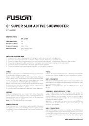
POWERPLANT<br />
COMPONENT SPEAKERS<br />
PP-CM525, PP-CM650<br />
Speaker Parameters<br />
PP-CM5250 PP-CM650<br />
Max Power Rating 210 Watts 280 Watts<br />
RMS Power Rating 95 Watts 120 Watts<br />
Frequency Response 50Hz - 22kHz 40Hz - 22kHz<br />
Impedance 4 Ohms 4 Ohms<br />
Sensitivity 90 dB 91 dB<br />
Mounting Depth 60mm 65mm<br />
Mounting Diameter 125mm 140mm<br />
Crossover Specifications<br />
2-way, passive Butterworth crossover network<br />
12db/octave slope rates<br />
Adjustable 3-point tweeter level<br />
High pass 3.5kHz<br />
Low pass 4.0kHz<br />
Installation Guidelines<br />
Before any wiring and installation is performed, FUSION recommends you first plan the complete installation process.<br />
Look at the wiring routing, speaker location, and fitment. Make sure you recheck the installation at completion.<br />
A correct front stage and stereo image can be achieved by proper speaker placement. Ideally, speakers need to be positioned<br />
where the sound produced is directed at the occupants of the vehicle. The adjustable tweeter supplied with FUSION<br />
PowerPlant Component Speakers is designed to make this easier.<br />
<strong>Fusion</strong> speakers have been designed to fit in many stock or factory positions in the vehicle FUSION recommends a location<br />
with sufficient air volume behind the speaker, for it to work within its frequency range.<br />
Installation Warning<br />
1. Ensure the vehicle 12 volt lead is removed from the battery before any equipment is connected.<br />
2. Investigate the vehicle gas tanks, brake lines, and electrical wiring locations before you begin installation.<br />
3. Attach the product securely to the vehicle to prevent damage in the event of an accident.<br />
4. Ensure all wiring is protected to avoid damage or pinching of the cables.<br />
Installation Guidelines:<br />
Bass/mid speaker installation<br />
1. Ensure there is adequate clearance and depth for the speaker to be mounted<br />
2. Use the supplied template to mark out the correct diameter hole<br />
3. Drill four holes for the mounting screws<br />
4. Correctly connect the crossover to the speaker. Observe polarity. The striped wire is the positive.<br />
5. Carefully study the mounting diagram before attempting to mount the speaker. Insert the speaker and grille frame<br />
and affix with the screws provided. Your PowerPlant speaker is provided with two choices of grille frame. The cus-<br />
tom grille is screwed directly into the frame of the speaker (see diagram A on reverse side). For the mesh grille,<br />
first remove the mesh, then fit the speaker and the grille. The mesh is fitted last by simply pushing the tabs on the<br />
mesh into the self-locking slots in the grille frame. (see diagram B on reverse side).
Diagram A - mesh grille Diagram B - Custom grille<br />
Mesh<br />
Grille<br />
Tweeter Installation<br />
Surface/angle mount<br />
FUSION offers three choices of mounting styles to accommodate the varying requirements for on and off axis mounting<br />
positions. The most important goal for tweeter placement is the need to keep an un-obstructed path on axis to approximately<br />
4” below the rear vision mirror. The reason for this is to enhance the perception of centre image. When mounting,<br />
make sure there is no wiring behind the mounting surface, use the tweeter mount that enables the best sound focus and<br />
use this as the template for drilling the mounting holes. Run the wiring back to the crossover.<br />
Flush mount<br />
First check that the tweeter can be flush mounted into the surface you have chosen, especially with regards to depth.<br />
Mark out a 50mm hole and cut this out. Having a hole saw will greatly improve the tidiness and the integrity of the hole.<br />
Assemble the rear mount with the spring clamp and press through from the rear of the mounting surface, then bayonet<br />
the front plate and the rear mount together as shown in the flush mount illustration. Run the wiring back to the<br />
crossover.<br />
Angle<br />
Flush<br />
90.4<br />
27.3<br />
Grille<br />
73.3<br />
66.0<br />
Surface<br />
Crossover Installation<br />
1. FUSION crossovers are manufactured specifically for use with the FUSION full range component system. Use of any<br />
other crossover may result in damage to one or more of the components.<br />
2. The x-over is designed for installation under the vehicle dash, under the rear parcel shelf or in the trunk of the<br />
vehicle. They should not be located where they are subject to moisture, such as a leaky door. If possible locate the<br />
crossovers closer to the speakers than the amplifier.<br />
3. Use the crossover to mark the mounting holes. Make sure there is sufficient clearance on the other side of the<br />
mounting surface and that the mounting surface is perfectly flat to avoid damage to the crossover.<br />
4. Drill two pilot holes for the screws and wire the crossovers.<br />
5. Cut the pre-run speaker cable to the correct length. Connect the cable to the crossover, ensure the correct<br />
polarity.<br />
6. Screw into position.<br />
7. Adjust the tweeter level by removing the lid and selecting the desired setting. There are three options available<br />
–3, 0, +3dB.<br />
SOURCE INPUT -<br />
SOURCE INPUT +<br />
TWEETER OUT -<br />
TWEETER OUT +<br />
WOOFER OUT -<br />
WOOFER OUT +