Service Manual - LF28
Service Manual - LF28
Service Manual - LF28

Create successful ePaper yourself
Turn your PDF publications into a flip-book with our unique Google optimized e-Paper software.
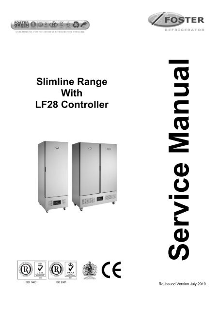
Slimline Range<br />
With<br />
<strong>LF28</strong> Controller<br />
ISO 14001 ISO 9001<br />
<strong>Service</strong> <strong>Manual</strong><br />
Re-Issued Version July 2010
Contents<br />
<strong>Manual</strong> Information & Health & Safety Notes 1<br />
Environmental Management Policy 2<br />
Disposal Requirements 2<br />
Cabinet Description 3<br />
Controller Operation 4<br />
User Functions 4<br />
Defrost Operation & Alarms 4 to 6<br />
Parameter Setting & Fuzzy Logic 6 to 7<br />
Controller Information Label 7<br />
Parameter Settings 8 to 10<br />
Wiring Diagrams 11 to 12<br />
Troubleshooting & Notes 13 to 15<br />
<strong>Service</strong> <strong>Manual</strong> Information<br />
The products and all information in this manual are subject to change without prior notice.<br />
We assume by the information given that the person(s) working on these refrigeration units are fully trained and skilled<br />
in all aspects of their workings. Also that they will use the appropriate safety equipment and take or meet precautions<br />
where required.<br />
The service manual does not cover information on every variation of this unit; neither does it cover the installation or<br />
every possible operating or maintenance instruction for the units.<br />
Health & Safety Warnings and Information<br />
Make sure the power supply is turned off before making any electrical repairs.<br />
To minimise shock and fire hazards, please do not plug or unplug the unit with wet<br />
hands.<br />
During maintenance and cleaning, please unplug the unit where required.<br />
Care must be taken when handling or working on the unit as sharp edges may cause<br />
personal injury, we recommend the wearing of suitable PPE.<br />
Ensure the correct moving and lifting procedures are used when relocating a unit.<br />
Do NOT use abrasive cleaning products, only those that are recommended. Never<br />
scour any parts of the refrigerator. Scouring pads or chemicals may cause damage by<br />
scratching or dulling polished surface finishes.<br />
Failure to keep the condenser clean may cause premature failure of the<br />
motor/compressor which will NOT be covered under warranty policy.<br />
Do NOT touch the cold surfaces in the freezer compartment. Particularly when hands<br />
are damp or wet, skin may adhere to these extremely cold surfaces and cause frostbite.<br />
Please ensure the appropriate use of safety aids or Personnel Protective Equipment<br />
(PPE) are used for you own safety.<br />
1
Environmental Management Policy for <strong>Service</strong> <strong>Manual</strong>s and Duets.<br />
Product Support and Installation Contractors<br />
Foster Refrigerator recognises that its activities, products and services can have an adverse impact upon the<br />
environment.<br />
The organisation is committed to implementing systems and controls to manage, reduce and eliminate its adverse<br />
environmental impacts wherever possible, and has formulated an Environmental Policy outlining our core aims. A<br />
copy of the Environmental Policy is available to all contractors and suppliers upon request.<br />
The organisation is committed to working with suppliers and contractors where their activities have the potential to<br />
impact upon the environment. To achieve the aims stated in the Environmental Policy we require that all suppliers and<br />
contractors operate in compliance with the law and are committed to best practice in environmental management.<br />
Product Support and Installation contractors are required to:<br />
1. Ensure that wherever possible waste is removed from the client‟s site, where arrangements are in place all waste<br />
should be returned to Foster Refrigerator‟s premises. In certain circumstances waste may be disposed of on the<br />
client‟s site; if permission is given, if the client has arrangements in place for the type of waste.<br />
2. If arranging for the disposal of your waste, handle, store and dispose of it in such a way as to prevent its escape<br />
into the environment, harm to human health, and to ensure the compliance with the environmental law. Guidance<br />
is available from the Environment Agency on how to comply with the waste management „duty of care‟.<br />
3. The following waste must be stored of separately from other wastes, as they are hazardous to the environment:<br />
refrigerants, polyurethane foam, and oils.<br />
4. When arranging for disposal of waste, ensure a waste transfer note or consignment note is completed as<br />
appropriate. Ensure that all waste is correctly described on the waste note and include the appropriate six-digit<br />
code from the European Waste Catalogue. Your waste contractor or Foster can provide further information if<br />
necessary.<br />
5. Ensure that all waste is removed by a registered waste carrier, a carrier in possession of a waste management<br />
licence, or a carrier holding an appropriate exemption. Ensure the person receiving the waste at its ultimate<br />
destination is in receipt of a waste management licence or valid exemption.<br />
6. Handle and store refrigerants in such a way as to prevent their emission to atmosphere, and ensure they are<br />
disposed of safely and in accordance with environmental law.<br />
7. Make arrangements to ensure all staff who handle refrigerants do so at a level of competence consistent with the<br />
City Guilds 2078 Handling Refrigerants qualification or equivalent qualification.<br />
8. Ensure all liquid substances are securely stored to prevent leaks and spill, and are not disposed of to storm<br />
drains, foul drain, or surface water to soil.<br />
Disposal Requirements<br />
If not disposed of properly all refrigerators have components that can be harmful to the environment. All old<br />
refrigerators must be disposed of by appropriately registered and licensed waste contractors, and in accordance with<br />
national laws and regulations.<br />
2
Slimline Cabinet Description<br />
The cabinets are manufactured as a one piece foamed shell.<br />
The condensing unit is located on the base of the cabinet.<br />
The cabinets conform to ISO Climate Class 5. (40 0 c with 40% RH)<br />
Temperature is controlled by a microprocessor control with digital temperature display.<br />
The refrigeration system is integral with an air-cooled condensing unit with the refrigerant distribution into the<br />
evaporator controlled by capillary.<br />
The cooled air is circulated through the evaporator, via the fan into the storage area.<br />
A plastic vaporiser tray with the hot gas line inserted into it is provided for condensate vaporisation.<br />
The FSL400 H, FSL600H and FSL 800 H have a temperature range of +1 0 c to +4 0 c with a timed off cycle defrost.<br />
The FSL400 L, FSL600L and FSL 800 L have a temperature range of -18 0 c to -21 0 c with electric defrost set at 4 times<br />
per 24 hours.<br />
The solid doors are fitted with pivot hinges, recessed door handle and magnetic door gasket.<br />
The glass doors are fitted with pivot hinges, surface mounted door handle and magnetic door gasket.<br />
On glass door models the interior light, incorporating the on/off switch, is fitted to the top of the storage area at the<br />
front.<br />
All models are fitted with lockable swivel castors to the front and swivel castors to the rear.<br />
Nomenclature based on –<br />
FSL = Foster Slim Line. 400/ 800 = Net Capacity (litres). H = High Temperature. L = Low Temperature.<br />
G = Glass Door<br />
Model Ref. FSL 400H FSL 400L FSL 800H FSL 800L<br />
Temperature range<br />
+1 0 c to<br />
+4 0 c<br />
3<br />
-18 0 c to<br />
-21 0 c<br />
+1 0 c to<br />
+4 0 c<br />
-18 0 c to<br />
-21 0 c<br />
Refrigerant R134a R404a R134a R404a<br />
Compressor<br />
Part Number<br />
00-555664 00-555680 00-555667 00-555681<br />
Capillary 3m x 042 2.5m 042 3m x 054 3m x 054<br />
Defrost Type<br />
Timed Off<br />
Cycle<br />
Electric<br />
Timed Off<br />
Cycle<br />
Electric<br />
Heat Output 680 1104 1300 1488<br />
Extraction Rate 400 520 780 730<br />
Voltage 220-1-50 220-1-50 220-1-50 220-1-50<br />
Power<br />
Consumption<br />
Watts 280 584 520 758<br />
Amps 2.1 3.8 3.6 4.1<br />
Fuse Rating Amps 13 13 13 13
Operation Guidelines for Foster controller part number LF 28B2SE-B (00-555920)<br />
Controller with the LCD 16 Display (00-555740) fitted as from May 2007 to November 2007<br />
Controller display LCD5s (00-555992) fitted as from November 2007<br />
Operation Guidelines<br />
Initial Start Up.<br />
Start Up & self Test:<br />
The indication is only displayed during the first three seconds following the mains electrical power being applied to the<br />
unit. During this period the controller performs a self-check.<br />
Once the self-check has been completed OFF<br />
will be displayed.<br />
Press and hold for three seconds. The unit will start and the air temperature will be displayed.<br />
Check temperature set point.<br />
Important to note that the ability to increase and decrease the set point is not a function available to the user as the<br />
set point is fixed. To make adjustments to the set point it is necessary to access the parameter and alter SPL and<br />
SPH accordingly.<br />
Check set point by pressing the button<br />
To increase set point press + until required temperature is displayed.<br />
To decrease set point press + until required temperature is displayed.<br />
Factory Temperature Set Point<br />
Refrigerator +1°C to +4°C<br />
Meat 0°C to 2°C.<br />
Freezer -18°C to -21°C.<br />
Exit from set up occurs after 10 seconds if no button is pressed.<br />
<strong>Manual</strong> Defrost.<br />
To initiate a manual defrost press and dEF hold will be displayed release.<br />
On completion of the defrost REC will be displayed until the cabinet temperature is achieved and then it will<br />
revert to displaying the normal cabinet temperature.<br />
Set Unit to Standby.<br />
Press display shows<br />
OFF<br />
This indication is displayed while the unit is not operating but with mains power applied to the unit. This mode may be<br />
used for internal cleaning regimes and short periods when the unit is not required.<br />
For extended periods of inactivity the mains supply should be isolated.<br />
4
Auto Defrost operation.<br />
The defrost frequency is determined by the usage of the machine.<br />
In the economy mode it may not perform a defrost as by monitoring the air temperature, evaporator temperature and<br />
door opening factor it may decide that there is insufficient ice build up on the evaporator so defrosting is not required.<br />
The parameter DFR (defrost frequency) is set for 3. The cabinet will perform at least 1 defrost per day and with the<br />
setting at 3 it has the potential to initiate up to 2 additional defrost in the economy mode.<br />
Should the cabinet experience constant usage the controller will switch automatically to the second parameter<br />
settings indicated by the controller LED adjacent to illuminating, which could under circumstances of heavy usage<br />
initiate up to 6 defrosts per day.<br />
The second parameter settings preceded by 11 will now be active,<br />
It is important to note that during the first few days of operation the defrosting frequency may be at regular intervals<br />
but these will reduce as the controller monitors the operation.<br />
Alarm and Warnings<br />
High temperature alarm<br />
HI Will be displayed.<br />
The alarm will sound but can be silenced by pressing any of the buttons, however it will return after the preset<br />
designated period. The unit returning to normal operating temperature will automatically cancel the alarm.<br />
Possible Causes: Evaporator fan not working. Restricted airflow through airduct. Evaporator iced up. Compressor not<br />
working.<br />
Low temperature alarm.<br />
LO<br />
Will be displayed.<br />
The alarm will sound but can be silenced by pressing any of the buttons and the unit will continue to operate, however<br />
it will return after the pre-set designated period. The unit returning to normal operating temperature will automatically<br />
cancel the alarm.<br />
Possible Causes: Controller faulty (not switching compressor off). Compressor secondary relay will not de-energise<br />
(low temperature models).<br />
Door Open Alarm. (Only applies to cabinets fitted with door switches.)<br />
DO<br />
Will be displayed.<br />
The alarm will sound but can be silenced by pressing.<br />
The display will continue to display the alarm message until cancelled by shutting the door.<br />
If the alarm cannot be cancelled by doing this call your Foster Authorised <strong>Service</strong> Company.<br />
Possible Causes: Faulty door switch. Door left open for more than 5minutes.<br />
High Pressure Alarm (Only applies to machines fitted with a condenser probe).<br />
HP<br />
Will be displayed<br />
This alarm relate to the condenser which must be checked and cleaned at regular intervals the frequency being<br />
determined by site conditions.<br />
The alarm will sound but can be silenced by pressing any of the buttons and the unit will continue to operate, however<br />
it will return after the pre-set designated period. The unit returning to normal operating temperature will automatically<br />
cancel the alarm.<br />
Possible Causes: Condenser fan not working. Condenser blocked/ dirty. Condenser obstructed.<br />
Air Temperature Probe Failure.<br />
E1<br />
Will be displayed.<br />
The alarm will sound but can be silenced by pressing any button.<br />
There is no further action that can be taken by the user in this instance. During this period the unit will continue to<br />
operate but have a reduced performance.<br />
Action: Replace Probe.<br />
Evaporator Temperature Probe Failure. (Automatic Defrost Cabinets Only)<br />
E2 Will be displayed.<br />
The alarm will sound but can be silenced by pressing any button.<br />
There is no further action that can be taken by the user in this instance. During this period the unit will continue to<br />
operate satisfactorily, but this failure will have an effect on the defrost and therefore efficiency if allowed to continue.<br />
Action: Replace Probe.<br />
5
Information Menu<br />
Pressing and releasing activates the information menu. From this menu you can display the<br />
temperature relating to T1 (air probe), T2 (evaporator probe, if fitted) and T3 (condenser probe, if fitted).<br />
The maximum temperature (THI) and the minimum temperature (TLO) the cabinet has achieved since it was last reset.<br />
The total operating time of the condenser (CND), since it was last cleaned, and the keyboard status (LOC).<br />
The information to be displayed can be selected sequentially by pressing repeatedly or scrolling<br />
through the menu using the or buttons.<br />
Once selected press to display the value<br />
Exit from the info menu by pressing or is automatic after 6 seconds if no buttons are pressed.<br />
To reset the temperature settings recorded in THI and TLO and the hours counted in CND, access the info menu<br />
press to display the value plus simultaneously for resetting to be completed.<br />
To check the LOC status scroll through to LOC, press to display status – YES to lock keys. – NO to<br />
leave keys accessible.<br />
NOTE: with the keys locked it is not possible to turn the unit off or ON or to check the set point<br />
Parameter Setting and Adjustment<br />
It is strongly advised that before adjusting any <strong>Service</strong> Parameters a thorough understanding of the following<br />
instructions should be obtained.<br />
The parameters are accessed by pressing the following keys in succession +<br />
and keeping them pressed for 5 seconds.<br />
After this period the first parameter ‘SCL’ will be displayed.<br />
Press button to pass from one parameter to the next and button to go back.<br />
Press to display the value + or to change it.<br />
Exit from set up is by pressing or is automatic if no buttons are pressed for 30 seconds<br />
NOTE:<br />
When receiving a replacement controller the unit will be set with the default settings. Change the settings to those<br />
relating to the particular model. After changing parameter „SCL‟ from „1‟ to „2‟ moving through parameters „SPL‟, „SP‟,<br />
„FDD‟, IISL‟ and „IISP‟ you may find that „-or‟ will be displayed. „-or‟ indicates that the control setting is out of range.<br />
To get the parameter back into range, for example „SPL‟, press to display the value +<br />
continue pressing both buttons until the display shows the temperature required then release both buttons.<br />
Use the same procedure to adjust all of the parameters displaying „-or‟.<br />
Fuzzy Logic.<br />
These are settings that maintain the temperature of the cabinet in a more energy efficient manner.<br />
It works by controlling the evaporator fan/s, defrost and temperature in low usage times by transferring the operation<br />
to a second set of economy parameters.<br />
When the cabinet is first switched On the economy settings control the operation of the temperature and will remain at<br />
those settings until the controller, by monitoring the door opening frequency and the air and evaporator temperatures,<br />
identifies a higher usage and switches over to the 11SM (2nd parameter set management).<br />
When the economy settings are activated the cabinet temperature is allowed to rise to the setting (SP) set point [1].<br />
This is set to a higher temperature setting to allow the air temperature to rise without having much of an impact on the<br />
product temperature.<br />
In addition the fan/s will modulate (cycle for 30 seconds) as set in (FPC) evaporator fan On / Off Ratio.<br />
The parameter is set at 1.<br />
Changing the setting to 0 will have the fan running with the compressor. Set to 1 the fan will run for 30 seconds on and<br />
60 seconds off. Set to 2 the fan will run for 60 seconds on and 60 seconds off and set to 3 the fan will run for 90<br />
seconds on and 60 seconds off.<br />
6
With FPC set to 1, 2 or 3 the fans will generate less heat into the cabinet therefore reduce the requirement of the<br />
condensing system.<br />
NOTE:<br />
Parameter FPC will only function with the parameter FTC set for YES. With FTC set to NO the fan will run all of the<br />
time apart from during defrost when it will be off during electric and hot gas defrost but on during a timed off cycle<br />
defrost.<br />
Fan Operation.<br />
The evaporator fan/s will run normally when the compressor is running but will commence cycling when the<br />
compressor is in the off cycle mode.<br />
The fans will run without the compressor during timed off cycle defrost but will not run during hot gas or electric<br />
defrost.<br />
For models that don‟t have door switches fitted the fuzzy logic will not function as the controller is unable to monitor<br />
door opening factors.<br />
Controller Information Label<br />
NOTE:<br />
When receiving a replacement controller the unit will be set with the default settings. Change the settings to those<br />
relating to the particular model. After changing parameter „SCL‟ from „1‟ to „2‟ moving through parameters „SPL‟, „SP‟,<br />
„FDD‟, IISL‟ and „IISP‟ you may find that „-or‟ will be displayed. „-or‟ indicates that the control setting is out of range.<br />
To get the parameter back into range, for example „SPL‟, press to display the value + continue<br />
pressing both buttons until the display shows the temperature required then release both buttons.<br />
Use the same procedure to adjust all of the parameters displaying „-or‟.<br />
7
Parameter settings for the FSL400H and FSL 800 H<br />
Mnem. Definition Min. Max Default Dim. H Temp<br />
SCL Readout scale 1°C; 2°C; °F 2 flag 2<br />
SPL Minimum set point [ I ] -40 SPH 1 °C 1<br />
SPH Maximum set point [ I ] SPL 40 3 °C 3<br />
SP Set point [ I ] SPL SPH 2 °C 2<br />
HYS Thermostat hysteresis [ I ] 0.1 10 3 °K 3<br />
CRT Minimum compressor rest time 0 30 2 min. 2<br />
CT1 Compressor run with T1 failure 0 30 7 min. 7<br />
CT2 Compressor stop with T1 failure 0 30 3 min. 3<br />
2CD Start delay 2nd compressor 0 120 0 sec. 0<br />
DFR Defrost frequency / 24h 0 24 2 1/24h 2<br />
DLI Defrost end temperature -40 40 20 °C 20<br />
DTO Maximum defrost duration 1 120 20 min. 20<br />
DTY Defrost type OFF; ELE; GAS OFF flag OFF<br />
DRN Drain down time 0 30 2 min. 2<br />
DDY Defrost display control 0 60 10 min. 10<br />
FID Fan activity during defrost NO YES YES flag YES<br />
FDD Fan re-start delay temperature -40 40 0 °C 0<br />
FTO Evaporator fan maximum time-out 0 120 3 min. 3<br />
FTC Evaporator fan timed control NO YES YES flag YES<br />
FT1 Fan stop delay 0 180 15 sec. 15<br />
FT2 Timed fan stop 0 30 2 min. 2<br />
FT3 Timed fan run 0 30 1 min. 1<br />
ATL Low alarm differential -12 0 -5 °K -5<br />
ATH High alarm differential 0 12 5 °K 5<br />
ATD Alarm Temperature Delay 0 120 90 min. 90<br />
AHT Condenser Alarm Temperature 0 75 60 °C 60<br />
AHM Condenser high temp. alarm operation NON; ALR; STP NON flag NON<br />
ACC Condenser cleaning period 0 52 0 wks 0<br />
HDS Sensitivity function eco / heavy duty 1 5 3 flag 3<br />
IISM 2nd parameter set switching mode NON; MAN; HDD; DI2 HDD flag HDD<br />
IISL Minimum 2nd temp. set -40 IISH 1 °C 1<br />
IISH Maximum 2nd temp. set IISL 40 3 °C 3<br />
IISP Effective 2nd temperature set point IISL IISH 1 °C 1<br />
IIHY Hysteresis 2nd temperature set 0.1 10 3 °K 3<br />
IIFT Evap. fan timed control in mode 2 NO YES NO flag NO<br />
IIDF Defrost Frequency / 24h in mode 2 0 24 4 1/24h 4<br />
SB Button 0/1 enabling NO YES YES flag YES<br />
DS Door switch enabling NO YES YES flag NO<br />
CSD Compressor stop delay from door opening 0 30 1 min. 1<br />
ADO Door alarm delay 0 30 8 min. 8<br />
D12 Function digital input D12 NON; HPS; IISM; RDS NON flag NON<br />
LSM Light switch mode NON; MAN; DOR NON flag NON<br />
OAU Control of AUX output NON; 0-1; LGT; 2CU; 2EU; ALR NON flag NON<br />
OS1 T1 (air) probe offset -12 12 0 °K 0<br />
T2 T2 (evap.) probe enabling NO YES NO flag NO<br />
OS2 T2 (evap.) probe offset -12 12 0 °K 0<br />
T3 T3 (cond.) probe enabling NO YES NO flag NO<br />
OS3 T3 (cond.) probe offset -12 12 0 °K 0<br />
T4 T4 (aux.) probe enabling NON; 2CU; 2EU NON flag NON<br />
OS4 T4 (aux.) probe offset -12 12 0 °K 0<br />
TLD Delay for min./max. temp storage 1 30 5 min. 5<br />
SIM Display slowdown 0 100 3 exp. 3<br />
ADR Unit peripheral address 1 255 1 exp. 1<br />
8
Parameter settings for the FSL400M and FSL800M<br />
Mnem. Definition Min. Max Default Dim. M Temp<br />
SCL Readout scale 1°C; 2°C; °F 2 flag 2<br />
SPL Minimum set point [ I ] -40 SPH 1 °C -2<br />
SPH Maximum set point [ I ] SPL 40 3 °C 0<br />
SP Set point [ I ] SPL SPH 2 °C -1<br />
HYS Thermostat hysteresis [ I ] 0.1 10 3 °K 2<br />
CRT Minimum compressor rest time 0 30 2 min. 2<br />
CT1 Compressor run with T1 failure 0 30 7 min. 7<br />
CT2 Compressor stop with T1 failure 0 30 3 min. 3<br />
2CD Start delay 2nd compressor 0 120 0 sec. 0<br />
DFR Defrost frequency / 24h 0 24 2 1/24h 4<br />
DLI Defrost end temperature -40 40 20 °C 20<br />
DTO Maximum defrost duration 1 120 20 min. 20<br />
DTY Defrost type OFF; ELE; GAS OFF flag ELE<br />
DRN Drain down time 0 30 2 min. 2<br />
DDY Defrost display control 0 60 10 min. 10<br />
FID Fan activity during defrost NO YES YES flag NO<br />
FDD Fan re-start delay temperature -40 40 0 °C 0<br />
FTO Evaporator fan maximum time-out 0 120 3 min. 3<br />
FTC Evaporator fan timed control NO YES YES flag YES<br />
FT1 Fan stop delay 0 180 15 sec. 15<br />
FT2 Timed fan stop 0 30 2 min. 3<br />
FT3 Timed fan run 0 30 1 min. 1<br />
ATL Low alarm differential -12 0 -5 °K -5<br />
ATH High alarm differential 0 12 5 °K 5<br />
ATD Alarm Temperature Delay 0 120 90 min. 90<br />
AHT Condenser Alarm Temperature 0 75 60 °C 60<br />
AHM Condenser high temp. alarm operation NON; ALR; STP NON flag NON<br />
ACC Condenser cleaning period 0 52 0 wks 0<br />
HDS Sensitivity function eco / heavy duty 1 5 3 flag 3<br />
IISM 2nd parameter set switching mode NON; MAN; HDD; DI2 HDD flag HDD<br />
IISL Minimum 2nd temp. set -40 IISH 1 °C -2<br />
IISH Maximum 2nd temp. set IISL 40 3 °C 0<br />
IISP Effective 2nd temperature set point IISL IISH 1 °C -2<br />
IIHY Hysteresis 2nd temperature set 0.1 10 3 °K 2<br />
IIFT Evap. fan timed control in mode 2 NO YES NO flag NO<br />
IIDF Defrost Frequency / 24h in mode 2 0 24 4 1/24h 4<br />
SB Button 0/1 enabling NO YES YES flag YES<br />
DS Door switch enabling NO YES YES flag NO<br />
CSD Compressor stop delay from door opening 0 30 1 min. 1<br />
ADO Door alarm delay 0 30 8 min. 8<br />
D12 Function digital input D12 NON; HPS; IISM; RDS NON flag NON<br />
LSM Light switch mode NON; MAN; DOR NON flag NON<br />
OAU Control of AUX output NON; 0-1; LGT; 2CU; 2EU; ALR NON flag NON<br />
OS1 T1 (air) probe offset -12 12 0 °K 0<br />
T2 T2 (evap.) probe enabling NO YES NO flag YES<br />
OS2 T2 (evap.) probe offset -12 12 0 °K 0<br />
T3 T3 (cond.) probe enabling NO YES NO flag NO<br />
OS3 T3 (cond.) probe offset -12 12 0 °K 0<br />
T4 T4 (aux.) probe enabling NON; 2CU; 2EU NON flag NON<br />
OS4 T4 (aux.) probe offset -12 12 0 °K 0<br />
TLD Delay for min./max. temp storage 1 30 5 min. 5<br />
SIM Display slowdown 0 100 3 exp. 3<br />
ADR Unit peripheral address 1 255 1 exp. 1<br />
9
Parameter settings for the FSL 400L and FSL800L<br />
Mnem. Definition Min. Max Default Dim. L Temp<br />
SCL Readout scale 1°C; 2°C; °F 2 flag 2<br />
SPL Minimum set point [ I ] -40 SPH 1 °C -21<br />
SPH Maximum set point [ I ] SPL 40 3 °C -19<br />
SP Set point [ I ] SPL SPH 2 °C -19<br />
HYS Thermostat hysteresis [ I ] 0.1 10 3 °K 3<br />
CRT Minimum compressor rest time 0 30 2 min. 2<br />
CT1 Compressor run with T1 failure 0 30 7 min. 7<br />
CT2 Compressor stop with T1 failure 0 30 3 min. 3<br />
2CD Start delay 2nd compressor 0 120 0 sec. 0<br />
DFR Defrost frequency / 24h 0 24 2 1/24h 4<br />
DLI Defrost end temperature -40 40 20 °C 20<br />
DTO Maximum defrost duration 1 120 20 min. 20<br />
DTY Defrost type OFF; ELE; GAS OFF flag ELE<br />
DRN Drain down time 0 30 2 min. 2<br />
DDY Defrost display control 0 60 10 min. 10<br />
FID Fan activity during defrost NO YES YES flag NO<br />
FDD Fan re-start delay temperature -40 40 0 °C 0<br />
FTO Evaporator fan maximum time-out 0 120 3 min. 3<br />
FTC Evaporator fan timed control NO YES YES flag YES<br />
FT1 Fan stop delay 0 180 15 sec. 15<br />
FT2 Timed fan stop 0 30 2 min. 3<br />
FT3 Timed fan run 0 30 1 min. 1<br />
ATL Low alarm differential -12 0 -5 °K -5<br />
ATH High alarm differential 0 12 5 °K 5<br />
ATD Alarm Temperature Delay 0 120 90 min. 90<br />
AHT Condenser Alarm Temperature 0 75 60 °C 60<br />
AHM Condenser high temp. alarm operation NON; ALR; STP NON flag NON<br />
ACC Condenser cleaning period 0 52 0 wks 0<br />
HDS Sensitivity function eco / heavy duty 1 5 3 flag 3<br />
IISM 2nd parameter set switching mode NON; MAN; HDD; DI2 HDD flag HDD<br />
IISL Minimum 2nd temp. set -40 IISH 1 °C -21<br />
IISH Maximum 2nd temp. set IISL 40 3 °C -21<br />
IISP Effective 2nd temperature set point IISL IISH 1 °C -21<br />
IIHY Hysteresis 2nd temperature set 0.1 10 3 °K 3<br />
IIFT Evap. fan timed control in mode 2 NO YES NO flag NO<br />
IIDF Defrost Frequency / 24h in mode 2 0 24 4 1/24h 4<br />
SB Button 0/1 enabling NO YES YES flag YES<br />
DS Door switch enabling NO YES YES flag NO<br />
CSD Compressor stop delay from door opening 0 30 1 min. 1<br />
ADO Door alarm delay 0 30 8 min. 8<br />
D12 Function digital input D12 NON; HPS; IISM; RDS NON flag NON<br />
LSM Light switch mode NON; MAN; DOR NON flag NON<br />
OAU Control of AUX output NON; 0-1; LGT; 2CU; 2EU; ALR NON flag NON<br />
OS1 T1 (air) probe offset -12 12 0 °K 0<br />
T2 T2 (evap.) probe enabling NO YES NO flag YES<br />
OS2 T2 (evap.) probe offset -12 12 0 °K 0<br />
T3 T3 (cond.) probe enabling NO YES NO flag NO<br />
OS3 T3 (cond.) probe offset -12 12 0 °K 0<br />
T4 T4 (aux.) probe enabling NON; 2CU; 2EU NON flag NON<br />
OS4 T4 (aux.) probe offset -12 12 0 °K 0<br />
TLD Delay for min./max. temp storage 1 30 5 min. 5<br />
SIM Display slowdown 0 100 3 exp. 3<br />
ADR Unit peripheral address 1 255 1 exp. 1<br />
10
High Temperature Models Wiring Diagram Using Foster Controller LF 28B2SE-B part number 00-555920<br />
11
Meat & Low Temperature Models Wiring Diagram Using Foster Controller LF 28B2SE-B part number 00-555920<br />
12
Troubleshooting<br />
Problem Possible Cause Solution<br />
Compressor will not start No voltage in socket Use voltmeter to check<br />
Electrical conductor or wires may be<br />
cut<br />
Use ohmmeter to check for continuity<br />
Defective electrical component:<br />
thermostat, relay, thermal protector etc<br />
Replace defective component<br />
Compressor motor has a winding open<br />
or shorted<br />
Measure ohmic resistance of main and<br />
auxiliary winding using ohmmeter.<br />
Compare with correct values<br />
Compressor stuck Change compressor<br />
The temperature is too cold Controller is set at a very cold position<br />
The temperature is not cold enough<br />
Temperature control contacts are open Repair or replace the contacts<br />
Incorrect wiring Check wiring diagram and correct<br />
Fuse blown or circuit breaker tripped. Replace fuse or reset circuit breaker<br />
Power cord unplugged Plug in power cord.<br />
Controller set too high Set controller to lower temperature.<br />
Cabinet in defrost cycle Wait for defrost cycle to finish<br />
Controller does not disconnect the<br />
condensing unit<br />
Control contacts are stuck closed<br />
Defective or incorrect temperature<br />
control<br />
Controller is set at a very warm<br />
position<br />
13<br />
Set to warmer position and check if the<br />
compressor stops according to<br />
controllers operating range.<br />
Check the insulation of the thermostat.<br />
If problem persists, change the<br />
thermostat<br />
Change the control. Check amperage<br />
load<br />
Determine correct control and replace.<br />
Adjust to colder setting<br />
Condenser is dirty Clean condenser<br />
The refrigerator has been placed at an<br />
inadequate location<br />
Compressor is inefficient or there is a<br />
high pressure due to the air in the<br />
system<br />
Iced up evaporator coil<br />
Restriction in system<br />
The refrigerator has been used<br />
improperly<br />
The unit must not be near stoves,<br />
walls that are exposed to the sun, or<br />
places that lack sufficient air flow.<br />
If there is air in the system, purge and<br />
recharge<br />
Check temperature control, refrigerant<br />
charge, and defrost mechanism.<br />
Remove all ice manually and start<br />
over.<br />
Locate exact point of restriction and<br />
correct<br />
The shelves must never be covered<br />
with any type of plastic or other<br />
material that will block the circulation<br />
of cold air within the refrigerator.<br />
Too many door openings Advise user to decrease if possible<br />
Excessive heat load placed in cabinet<br />
The refrigerator has been overcharged<br />
with the refrigerant gas<br />
Advise user not to put in products that<br />
are too hot.<br />
Check to see if condensation or ice<br />
crystals have formed on the suction<br />
line. If so, charge with the correct<br />
amount of gas.
Electrical Shocks<br />
Noise<br />
Extreme condensation inside the<br />
refrigerator<br />
No illumination (Glass door models<br />
only)<br />
Condensing unit runs for<br />
long periods of time<br />
The refrigerant gas is leaking<br />
The evaporator and/or condenser fans<br />
are not working<br />
14<br />
Find the location of gas leak in order to<br />
seal and replace the defective<br />
component. Change the drier. Perform<br />
a good vacuum and recharge unit.<br />
Check electrical connections and<br />
make sure that the fan blade isn‟t<br />
stuck. Replace the fan motor if it<br />
doesn‟t work.<br />
Re-arrange product to allow for proper<br />
air flow. Make sure there is at least<br />
Blocking air flow<br />
four inches of clearance from<br />
evaporator.<br />
Fuse blown or circuit breaker tripped Replace fuse or reset circuit breaker.<br />
Wires or electrical components are in<br />
direct contact with metallic parts.<br />
The refrigerator is not properly levelled<br />
The condenser is not fastened<br />
correctly. Copper tubing is in contact<br />
with metal<br />
The evaporator and/or condenser fans<br />
are loose<br />
Check for appropriate insulation on the<br />
connections of each component.<br />
Check if the noise goes away after you<br />
level the refrigerator<br />
While the compressor is working,<br />
check to see if metal parts are in<br />
contact with one another and/or if the<br />
screws that fasten the condenser are<br />
tightened.<br />
Check if the fans are securely<br />
fastened. Also, check if the fan blades<br />
are loose, broken or crooked. If so,<br />
change the faulty blade.<br />
If the noise persists after all other<br />
Compressor has an internal noise measures have been taken, it may be<br />
originating from the compressor.<br />
Loose part(s) Locate and tighten loose part(s)<br />
Controller is set at a very cold position<br />
The outside environment‟s relative<br />
humidity is very high (over 75%)<br />
The refrigerator door wont shut<br />
completely<br />
The refrigerator had been placed at an<br />
inadequate location<br />
Set the controller to a warmer position<br />
& check to see if compressor stops as<br />
should.<br />
This type of occurrence is caused by<br />
local climatic conditions and not by the<br />
refrigeration unit.<br />
Check the door and/or the magnetic<br />
gasket. Adjust the door hinges if<br />
needed; replace the gasket if broken.<br />
The unit must not be near sources that<br />
produce too much heat.<br />
The light switch is “off” position Press the light switch to “on” position<br />
False contact on the light switch, the<br />
fluorescent tube, or the ballast<br />
Light switch, ballast and/or fluorescent<br />
tube are damaged<br />
Excessive amount of warm product<br />
placed in cabinet<br />
Prolonged door opening or door ajar<br />
Door gasket(s) not sealing properly<br />
Inspect all connections<br />
Replace the damaged component.<br />
Advise user to leave adequate time for<br />
products to cool down<br />
Advise user to ensure doors are<br />
closed when not in use and to avoid<br />
opening doors for long periods of time.<br />
Ensure gaskets are snapped in<br />
completely. Remove gasket and wash<br />
with soap and water. Check condition<br />
of gasket & replace if necessary
Dirty condenser coil Clean condenser coil<br />
Evaporator coil iced over<br />
Notes<br />
15<br />
Unplug unit and allow coil to defrost.<br />
Make sure thermostat is not set too<br />
cold. Ensure that door gasket(s) are<br />
sealing properly. Select manual<br />
defrost and ensure system works.
Foster European Operations<br />
France<br />
Foster Refrigerator France SA<br />
Tel: (33) 01 34 30 22 22. Fax: (33) 01 30 37 68 74.<br />
Email: commercial@fosterfrance.com<br />
Germany<br />
Foster Refrigerator Gmbh,<br />
Tel: (49) 781 990 7840. Fax (49) 781 990 7844.<br />
Email: info@foster-gmbh.de<br />
Foster Refrigerator<br />
Oldmedow Road<br />
Kings Lynn<br />
Norfolk<br />
PE30 4JU<br />
Tel: 0843 216 8833<br />
Fax: 0843 216 4707<br />
Website: www.fosterrefrigerator.co.uk<br />
Email: support@foster-uk.com<br />
a Division of „ITW (UK) Ltd‟<br />
SLIMLINE <strong>LF28</strong>/SM 07/10<br />
16