Instructions for electrical actuator J2 - G. Bee
Instructions for electrical actuator J2 - G. Bee
Instructions for electrical actuator J2 - G. Bee

Create successful ePaper yourself
Turn your PDF publications into a flip-book with our unique Google optimized e-Paper software.
General<br />
explanations<br />
Standard -<br />
equipments<br />
Conditions<br />
Connection<br />
Maintenance<br />
Mounting<br />
Set in<br />
operation<br />
17.04.2007 Dat.:10.2.10.1 Seitenzahl 1 von 4<br />
10.03.2005<br />
Erstellt: FU<br />
Geändert PK<br />
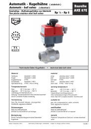
The electromechanical vane <strong>actuator</strong>s J+J ® <strong>for</strong> manipulation of industrial valves with an angle<br />
of traverse of 0-90° / 0-180° or a freely definable angle of traverse are assembled quite compactly and equipped<br />
completely to be taken in use without problems. Because of the clear structure and<br />
the maintenance-free operation, flexibility and security as well as the mechanical unblocking the <strong>actuator</strong>s are<br />
straight<strong>for</strong>ward and tolerant towards errors in use.<br />
This tolerance is supported by versatile systems as ETL (Electronic Torque Limiting), AVS (Automatic Voltage<br />
Sensing), ATC (Automatic Temperature Control) and PEC (Protected Consistent Electrical Connection) to<br />
improve quality and handling.<br />
The <strong>actuator</strong>s are driven by engines which are connected with the mainshaft through gears. Through redirecting<br />
these gears it is possible to declutch the engines on manual working. Here the current of the engine is<br />
interrupted. As the manual emergency manipulation is firmly installed, the armature can be operated via<br />
handwheel or via locking handle right after switching over. The travel stops take place through 2 integrated<br />
micro-switches. These switches are operated through cams which are placed directly onto the mainshaft.<br />
Beyond that there are 2 further, floating limit switches <strong>for</strong> signal generating. There is no mechanical travel stop.<br />
The optical position indicator on the <strong>actuator</strong> gives in<strong>for</strong>mation about the position of the armature. At the<br />
interface of the armature, which is con<strong>for</strong>ming to standards, appropriate armatures can be mounted directly or<br />
with the help of suitable adapters. The <strong>electrical</strong> connection is made by plugs. A nameplate as well as a socket<br />
plan / connection diagram makes it easy to identify the <strong>actuator</strong>.<br />
An electronic torque limiter is fitted to all <strong>J2</strong> <strong>actuator</strong>s. The ETL constantly monitors the motor load and<br />
immediately cuts the motor power supply if the ‘set point’ is exceeded. An internal LED, visible through the<br />
<strong>actuator</strong>’s housing, provides constant status indication: constantly lit LED = <strong>actuator</strong> working normally, flashing<br />
LED = fault warning, the torque in the valve has exceeded the ‘set point’. This advises operators that a problem<br />
has arisen with the valve (eg: blockage). A flashing LED indicates a f ault with the valve, not the <strong>actuator</strong>. The<br />
ETL automatically backs off’ when activated to relax the gears, allowing the manual override to be used to assist<br />
in clearing the blockage. Once the cause of the excess torque has been cleared, the <strong>J2</strong> will automatically reset,<br />
the LED will change to being constantly lit, and the <strong>actuator</strong> will start operating again. See instructions overleaf.<br />
ATC (Auto Temperature Control):An inbuilt thermostat and heater maintains the internal temperature at around<br />
30°C to prevent the possibility of condensation <strong>for</strong>ming within the housing. This system does not require a<br />
separate power supply, it is fed from the main power supply. The power supply must remain on at all times <strong>for</strong><br />
the heater to operate.<br />
All <strong>J2</strong> <strong>actuator</strong>s have a manual override facility to allow manual operation in the event of power failure. Selection<br />
of manual (‘MAN’ ) operation operates an internal switch which cuts the motor power – the <strong>actuator</strong> will not<br />
operate <strong>electrical</strong>ly whilst in manual.<br />
All <strong>J2</strong> <strong>actuator</strong>s have an additional pair of volt free mechanical micro-switch contacts which are typically used <strong>for</strong><br />
remote position confirmation. These switches are NOT to be used <strong>for</strong> <strong>actuator</strong> motor control.<br />
The connection occurs by means of the provided wall plugs. Here one should pay attention to the suitable cable<br />
diameter because otherwise the thightness is not ensured. In principle the wiring suggestions, the tensions and<br />
other data presented on the print of the <strong>actuator</strong> are valid. With discrepancies and any malfunctions you should<br />
absolutely confer in order to avoid destruction or damages.<br />
Complete units, consisting of armature and <strong>actuator</strong>, only have to be wired over the plugs. Opening the <strong>actuator</strong><br />
is only necessary if one has to adjust it. Connection, start-up or opening of the<br />
<strong>actuator</strong>s may only take place by technical personal considering VDE regulations.<br />
All J+J ® <strong>actuator</strong>s have to be connected single-phase, have to be mutual bolted and actuated by a relay or a<br />
switch. Please intend an external f use. The interface of the armature has to be arranged according to<br />
DIN3337/ISO5211 and has to guarantee an alignment of <strong>actuator</strong> and the driving shaft of the armature.<br />
The driving shaft of the armature has to bee shorter than accommodation of the <strong>actuator</strong>.<br />
The technical requirements have to be according to the per<strong>for</strong>mance data of the <strong>actuator</strong>s.<br />
A blocking of the driving shaft or the manual operating facilities may cause damages on the <strong>actuator</strong>.<br />
These <strong>actuator</strong>s are designed to be maintenance free, the gearbox is factory lubricated <strong>for</strong> life and there are no<br />
internal parts that require maintenance. With rarely used <strong>actuator</strong>s it is recommended to carry out a rule<br />
examination of the functions in accordance with the safety requirements. After the start-up the connection<br />
between <strong>actuator</strong> and armature should be examined after some running time. Here the operation smoothness of<br />
the armature has to be examined, too. Generally one has to pay attention to the close seat of the cover and the<br />
thightness of the cable gland. Unused plugs have to be locked.<br />
The J+J ® <strong>actuator</strong>s may not install over head. (Flange upwards) Please consider the accessibility of the hand<br />
emergency manipulation and the visibility of the position indicator. Depending on the type, the <strong>actuator</strong> is<br />
adjusted according to the print. Possibly the angle of traverse as to be adapted corresponding to the armature.<br />
With applications in the external area the <strong>actuator</strong> has to be protected by suitable measures in<br />
order to keep the permissible temperature range. To avoid condensation one should respect the wiring variant<br />
<strong>for</strong> switch room heating.<br />
Beyond that the <strong>actuator</strong>s have to be protected against environmental influences (rain, snow, etc.)<br />
in order to avoid any malfunction or failure.<br />
On part of the plant construction and/or the operator maintenance cycles and test cycles have to be stipulated<br />
according to the employment- and safety requirements. Beyond that one has to go into<br />
the particulars of control characteristics with the help of guidances and documentations.<br />
Be<strong>for</strong>e start-up please check the following circumstances:<br />
-Does the <strong>actuator</strong> correspond to the demanded model? (Torque, protection class, voltage, etc.)<br />
-Does the wiring correspond to the kind of tension (see diagram)<br />
-Can the armature be operated via hand emergency manipulation without large energy expenditure?<br />
-Is there a switch room heating necessary? (With reaching the end positions the tension has to remain on)<br />
<strong>Instructions</strong> J+J ® <strong>J2</strong> <strong>actuator</strong>s Model:<br />
L+H 20, 55, 140, 300<br />
Subject to modification<br />
e<br />
J+J Deutschland GmbH<br />
Auf der Hackelmasch 1 – D 31061 Alfeld<br />
Tel.: +49 5181 6017 - Fax: +49 5181 6032
Malfunctioning:<br />
- It does not pass nothing: Switch from manual to open. Wiring (AC or DC) is attached the plug? Does tension arrives the plug?<br />
- The drive starts and remains then standing: At the long side of the drive flashes in the housing a red light (if necessary only with<br />
opened drive recognizably - to open only by technical personnel!) Limiter actively, valve difficult to operate or blocks or <strong>for</strong><br />
operation by the drive model unsuitably. Eliminate reason <strong>for</strong> overloading or select stronger drive.<br />
- it is recognizable no flare signal: Ex ternal safety device or fuse blown / if necessary replace wiring fuse.<br />
- Drive stands on open, valve is however closed or <strong>for</strong> valve opens and closes not completely drive rotated developed or<br />
endposition adjustment agrees not with valve: The releasing cams must again be adjusted, and/or the drive is to be developed<br />
correctly. The limit switches <strong>for</strong> position signal do not react to wiring examine: adjustment of the releasing cams in such a way<br />
examine and stop that the switches are operated briefly be<strong>for</strong>e reaching the procedure way border.<br />
-The drive proceeds, which valve however not adjusts: the interface between valve and drive is incorrectly or defectively, hold<br />
consultation with the supplier and examine if necessary total documentation.<br />
-The end position is reached, the Limiter is active (light flashes): mark the position of the position-indication, switch to Manual and<br />
turn back drive manually easily from the final position and turn again in direction of the final position.<br />
- Do you encounter increased reconditions must the valve be examined have the valve of final notices those were not removed ><br />
notices to remove condition <strong>for</strong>eign matter in the valve (cloth around shut-off valve, solids in death areas or the like), are<br />
defective the seal? > valve repair/ consultation with valve supplier hold. The integrated Limiter represents a protection device, in<br />
order to Avoid damage <strong>for</strong> such problems, a constant utilization (e.g. drive on valve notices) can however to damage to valve,<br />
adapters and drive follow. Such errors must be eliminated thus as fast as possible.<br />
Potentiometer<br />
(Optional)<br />
Positioner<br />
(Optional)<br />
BSR/<br />
AKKU-<br />
Battery<br />
pack<br />
(Optional)<br />
Outfit:<br />
17.04.2007 Dat.:10.2.10.1 Seitenzahl 2 von 4<br />
10.03.2005<br />
Erstellt: FU<br />
Geändert PK<br />
Options:<br />
With the special equipment „potentiometer” is possible a resistance-dependent position sensing of the drive.<br />
Here the connection diagram applies to potentiometers (see below), the potentiometer by the drive main shaft<br />
over a gear wheel is propelled, the min value represents the position "CLOSED".<br />
The DPS position control is in accordance with drive identification plate on 4-20mA or 0-10V configures, an<br />
appropriate exit <strong>for</strong> feedback is integrated. The connection takes place in accordance with connection diagram.<br />
The control signal must be floating. For the avoidance of operational errors may not be proceeded the drive in<br />
the manual enterprise over the indicated terminator points (0-90° or 0-180°). Thus nothing is damaged, but a<br />
reprogramming of the terminator points could become necessary (separate guidance).<br />
Important notes to potentiometer and position control: With proceeding over the preset stroke the adjustment<br />
must take place opposite or it must a 360° adjustment take place so long to the initial value is again reached. We<br />
use a stop free potentiometer and by the speed ratio shift the "zero point" with each 360° turn, until it agrees after<br />
several turns again.<br />
The BSR safety pack contains a battery inclusive load electronics, which ensures with power failure a safety<br />
adjustment (open or close) to the valve. Continuous operation with power failure is not possible hereby,<br />
otherwise the drive can be operated like the standard drives. Consider the different wiring (drawer control tension<br />
and current on contact).The charging voltage must fit constantly with it the battery is if necessary loaded. Here if<br />
tension lies close and the switching contact with tension is subjected, the drive proceeds opposite <strong>for</strong> safety<br />
position. If the switching contact is unloaded or if this current or the charging current precipitates, the emergency<br />
adjustment is released. The batteries used has a long life span, which is however dependent on the operating<br />
conditions. Thus a rule examination of the drives is to be planned based on the safety requirements.<br />
1 : Main supply<br />
2 : Options - Auxiliaries<br />
3 : Options - Auxiliaries:: Connector <strong>for</strong> positioner, output potentiometer<br />
4 : Connector <strong>for</strong> extra limit switches<br />
A : Manual / Automatic switch<br />
B : Handwheel At model 20 lever / optical position indicator and manual override.<br />
C : Optical position indicator<br />
D: Wiring diagram<br />
D<br />
Model L/H 20<br />
B<br />
A<br />
<strong>Instructions</strong> J+J ® <strong>J2</strong> <strong>actuator</strong>s Model:<br />
L+H 20, 55, 140, 300<br />
Subject to modification<br />
D<br />
Model L/H 55<br />
B<br />
C<br />
A<br />
Model L/H 140+300<br />
C B<br />
J+J Deutschland GmbH<br />
Auf der Hackelmasch 1 – D 31061 Alfeld<br />
Tel.: +49 5181 6017 - Fax: +49 5181 6032<br />
info@juj-deutschland.de - www.juj-deutschland.de<br />
D<br />
A
Main Data:<br />
Model max. current Modell H<br />
85 -240V<br />
(+/- 5%)<br />
20 85VAC: 330mA / 28,05W<br />
85VDC: 290mA / 24,65W<br />
110VAC: 202mA / 22,22W<br />
110VDC: 180mA / 19,8W<br />
220VAC: 99mA / 21,78W<br />
17.04.2007 Dat.:10.2.10.1 Seitenzahl 3 von 4<br />
10.03.2005<br />
Erstellt: FU<br />
Geändert PK<br />
240VAC: 88mA / 21,12W<br />
55 85VAC: 400mA / 34W<br />
85VDC: 430mA / 36,55W<br />
110VAC: 257mA / 28,27W<br />
110VDC: 280mA / 30,8W<br />
220VAC: 120mA / 26,4W<br />
240VAC: 115mA / 27,6W<br />
140 85VAC: 700mA / 59,8W<br />
85VDC: 610mA / 31,85W<br />
110VAC: 340mA / 37,4W<br />
110VDC: 270 mA / 29,7W<br />
220VAC: 155 mA / 34,1W<br />
240VAC: 150mA /36W<br />
300 85VAC: 750mA / 63,75W<br />
85VDC: 800mA / 68W<br />
110VAC: 440mA / 48,4W<br />
110VDC: 470mA / 51,7W<br />
220VAC: 230mA / 50,6W<br />
240VAC: 240mA / 57,6W<br />
Common Data:<br />
max. current Modell L<br />
12-48V DC (-0/+ 5%)<br />
15-48V AC (-0/+5%)<br />
15VAC: 2400mA / 36W<br />
12VDC: 2600mA / 31,2W<br />
24VAC: 840mA / 20,16W<br />
24VDC: 680mA /16,32W<br />
48VAC: 460mA / 22,08W<br />
48VDC: 400mA / 19,2W<br />
15VAC: 3900mA / 58,5W<br />
12VDC: 2580mA /30,96W<br />
24VAC: 1110mA / 26,64W<br />
24VDC: 1110mA / 26,64W<br />
48VAC: 560mA / 26,88W<br />
48VDC: 600mA / 26,8W<br />
15VAC: 6400mA / 96W<br />
12VDC: 4130mA / 49,56W<br />
24VAC: 1620mA / 38,88W<br />
24VDC: 1430mA / 34,32W<br />
48VAC: 590mA / 28,32W<br />
48VDC: 600mA / 28,8W<br />
15VAC: 6900mA / 103,5W<br />
12VDC: 4770mA / 57,24W<br />
24VAC: 1800mA /43,2W<br />
24VDC: 1600mA / 38,4W<br />
48VAC: 1000mA / 48W<br />
48VDC: 1010mA / 48,48W<br />
<strong>Instructions</strong> J+J ® <strong>J2</strong> <strong>actuator</strong>s Model:<br />
L+H 20, 55, 140, 300<br />
Subject to modification<br />
Max.<br />
torque<br />
Nm<br />
Working- time<br />
<strong>for</strong> 90°/<br />
25 Nm L20 = 8 sec.<br />
(+/- 10%)<br />
H20 = 9,5 sec.<br />
(+/- 10%)<br />
60 Nm L55 = 10 sec.<br />
(+/- 10%)<br />
H55 = 11 sec.<br />
(+/- 10%)<br />
170 Nm L140 = 31 sec.<br />
(+/- 10%)<br />
H140 = 31 sec.<br />
(-10% / +20%)<br />
350 Nm L300 = 60 sec.<br />
(+/- 10%)<br />
H300 = 66 sec.<br />
(+/- 10%)<br />
Duty Temperature range Heater Safety class<br />
IEC60529<br />
Lim.- switches*<br />
75% -20 / +70°C 4W IP65 250VAC 3A<br />
Weight:<br />
Model "20" Model "55" Model "140" Model "300"<br />
1,5 Kg 2,4 Kg 5,2 Kg 5,2 Kg<br />
Further dates on request. Other switches (gold contacts) possible.<br />
Wiring Diagram:<br />
N /<br />
L /<br />
1<br />
<strong>J2</strong> Standard - AC / DC 3 Wires<br />
VAC / VDC<br />
3<br />
Plug 1<br />
CLOSE<br />
2<br />
OPEN<br />
1<br />
CLOSE OPEN<br />
3<br />
Plug 4<br />
2<br />
VDC<br />
1<br />
<strong>J2</strong> Standard - DC 2 Wires (alternative)<br />
3<br />
CLOSE<br />
2<br />
OPEN<br />
J+J Deutschland GmbH<br />
Auf der Hackelmasch 1 – D 31061 Alfeld<br />
Tel.: +49 5181 6017 - Fax: +49 5181 6032<br />
info@juj-deutschland.de - www.juj-deutschland.de<br />
1<br />
3<br />
CLOSE<br />
Plug 1 Plug 4<br />
2<br />
OPEN
Adjustment:<br />
Adjustment instruction limit switches <strong>J2</strong><br />
All work in the drive may be accomplished only by qualified technical personnel and with switched off voltage supply.<br />
Affecting live components can have and to the damage of electronics lead a dangerous <strong>electrical</strong> impact to the consequence! Purpose: The<br />
drives are pre-adjusted. Dependent on the use, lacking aligning of valve connections or adapters, it can be necessary the drive in its strokeends on the<br />
respective valve to adapt or feedbacks circuit differently to adjust. Sometimes a readjusting can become necessary after longer employment<br />
under strong vibrations. Note: All screws and seals are to be brought after the assembling into their original position. Consider the references of the<br />
valve manufacturer and if necessary instructions of the plant const ructor.<br />
Preparing measures:<br />
1. Plugs after loosening of the fixing screws take off (seals consider).<br />
2. (only model 55, 140, 300)<br />
loosen the screws of the handwheel and take handwheel off.<br />
3. Take off indicator and/or lever carefully with a broad screwdriver<br />
after above <strong>for</strong>ce away. 4. The housing screws loosen and take.<br />
5. Covers carefully straight take off upward and do not rotate, if<br />
necessary with model 140 and 300 upper section with both hands press<br />
upward (levers with a screwdriver can lead to leakages). Covers aside<br />
put (cables to be able to remain connected with the plate, however absolutely consider<br />
them the cable run, which must be restored <strong>for</strong> the assembly).<br />
6. Put handwheel/ lever or indicator and fix the screws.<br />
Proceeding: Switch from AUTO to MAN and drive to position by<br />
handwheel, which shall be changed.<br />
Engine shut-down: You can use a 2mm Allen key or a small screwdriver now into the gap S of the cam put and rotate the cam to the clicking noise<br />
of the switch to hear<br />
are. Turn the cam from the direction with that the main shaft on the position will always turn to the switching flag near.<br />
End position signal: The adjustment of the end positions takes place in the same<br />
way or by means of a continuity tester. The continuity tester is attached to pin 1 and 2 (closed position) or to pin 1 and 3 of the end position plug (see<br />
connection diagram).<br />
The signal levers must be adjusted in such a way that they are released briefly be<strong>for</strong>e reaching<br />
the engine shut-down. Naturally they can be adjusted also on any point in the swivelling range of the drive over e.g. intermediate positions to indicate.<br />
Note: The adjusting tool may not be supported when adjusting the end positions at drive construction units. Examine afterwards the elevator position<br />
of the cams, shifting upward can to<br />
the consequence have that a cam affects 2 switching flags. If necessary are to be shifted after cams down.<br />
Assembly: After conclusion of the adjustment the cover is carefully remounted. Pay<br />
attention to lead the cables past as in the starting situation at the<br />
waves and the engine so that it cannot come to malfunctions by getting jammed. The cover must rest upon now closely the lower part. This is<br />
the case does not lie a cable possibly between engine and cover or is gotten jammed between lower part and cover. The cover lies closely on<br />
can you the screws use and crosswise tighten. Put afterwards the flaps position indicator on, the handwheel or the lever put on and fix. After the<br />
<strong>electrical</strong> connections are manufactured and were switched the drive under easy rotation of the handwheel or lever by AUTO to MAN, you can<br />
examine the <strong>electrical</strong> function. If the function should be incorrect, the procedure is to be repeated carefully. With questions please contact with the<br />
J+J ® Service.<br />
17.04.2007 Dat.:10.2.10.1 Seitenzahl 4 von 4<br />
10.03.2005<br />
Erstellt: FU<br />
Geändert PK<br />
Mod.20/55<br />
Mod.140+300<br />
ähnl.<br />
Boards<br />
electr. components<br />
A= downer, D= upper<br />
cam<br />
Position of cams<br />
B<br />
A<br />
<strong>Instructions</strong> J+J ® <strong>J2</strong> <strong>actuator</strong>s Model:<br />
L+H 20, 55, 140, 300<br />
Subject to modification<br />
D<br />
C<br />
Motor<br />
... ..<br />
...<br />
...<br />
Signal OPEN<br />
Signal CLOSED<br />
Switches<br />
shaft / cams<br />
S<br />
Motor stop OPEN<br />
Motor stop CLOSED<br />
J+J Deutschland GmbH<br />
Auf der Hackelmasch 1 – D 31061 Alfeld<br />
Tel.: +49 5181 6017 - Fax: +49 5181 6032<br />
info@juj-deutschland.de - www.juj-deutschland.de