Mágneskapcsolók 2,2 ... 132 kW - GANZ Kapcsoló- és ...
Mágneskapcsolók 2,2 ... 132 kW - GANZ Kapcsoló- és ...
Mágneskapcsolók 2,2 ... 132 kW - GANZ Kapcsoló- és ...

Create successful ePaper yourself
Turn your PDF publications into a flip-book with our unique Google optimized e-Paper software.
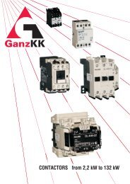
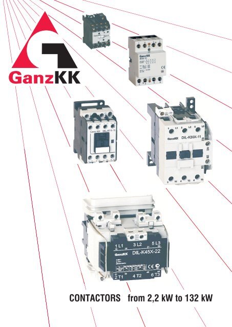
CONTACTORS from 2,2 <strong>kW</strong> to <strong>132</strong> <strong>kW</strong>
Contactors 2,2...<strong>132</strong> <strong>kW</strong> ATTENTION !<br />
DLK-4-10 DLK-5-10 DLK-7-10 DLK-11-10<br />
HLK-...<br />
01<br />
01<br />
01<br />
01<br />
DLK-15 DLK-18<br />
DLK-7/c-10<br />
S..<br />
DLK-45X-22<br />
DLK-55X-22<br />
H6<br />
BB<br />
DLK-15/c-11<br />
PKB11<br />
DLK-30/c-11<br />
DLK-37/c-11<br />
DLK-75X-22<br />
DLK-90X-22<br />
H0-2K T63I<br />
LA2<br />
LA3<br />
DLK-22X-11 DLK-30X-11<br />
DLK-110X-22<br />
DLK-<strong>132</strong>X-22<br />
PK22E<br />
YD-..<br />
KS-.. KS-..<br />
RC-K<br />
V-K<br />
D-K<br />
MV-e<br />
BO<br />
MH<br />
MK2-..<br />
IK21<br />
DLK-37X-11<br />
MK4-..<br />
IK40<br />
IK63<br />
Hi-..<br />
Li-..<br />
<strong>GANZ</strong> <strong>Kapcsoló</strong>- <strong>és</strong> K<strong>és</strong>zülékgyártó Kft.
The type-symbol DIL-K is changed to DLK<br />
Accessories for contactors<br />
PKB11<br />
side mounting<br />
auxiliary contact<br />
block<br />
LA 2<br />
or<br />
LA 3<br />
pneumatic timer<br />
RC-K V-K<br />
DLK- ...<br />
MV-e<br />
mechanical<br />
interlock DLK- ...<br />
DLK-...-11<br />
H0-2K<br />
thermal relay<br />
plug-in to<br />
contactor<br />
Hi-<br />
or<br />
Li- auxiliary contact<br />
block<br />
BO<br />
supressor<br />
BB<br />
mechanical<br />
interlock<br />
PK22E<br />
auxiliary contact block<br />
Contactors 2,2...<strong>132</strong> <strong>kW</strong><br />
Overvoltage protector, supressor<br />
DLK-...-11<br />
T63I<br />
thermal relay<br />
plug in to contactor<br />
PKB11<br />
side mounting<br />
auxiliary contact<br />
block<br />
<strong>GANZ</strong> <strong>Kapcsoló</strong>- <strong>és</strong> K<strong>és</strong>zülékgyártó Kft. 1<br />
D-K<br />
S11<br />
or<br />
S20<br />
side mounting<br />
auxiliary contact block<br />
YD<br />
star-delta timer
Contactors 2,2...<strong>132</strong> <strong>kW</strong><br />
1. Types<br />
2<br />
MK 2-10<br />
MK 4-10<br />
MK 4/G-10<br />
MK 2-01<br />
MK 4-01<br />
MK 4/G-01<br />
HLK- 31<br />
HLK- 22<br />
HLK- 40<br />
HLK- 44<br />
HLK- 62<br />
HLK(G)- 21<br />
HLK(G)- 30<br />
HLK(G)- 43<br />
HLK(G)- 52<br />
DLK-4-10<br />
DLK-5-10<br />
DLK-7-10<br />
DLK-11-10<br />
DLK-4-01<br />
DLK-5-01<br />
DLK-7-01<br />
DLK-11-01<br />
DLK-4-10d<br />
DLK-5-10d<br />
DLK-7-10d<br />
DLK-11-10d<br />
DLK-4-01d<br />
DLK-5-01d<br />
DLK-7-01d<br />
DLK-11-01d<br />
A2<br />
A2<br />
A2<br />
A2<br />
A1 1L1 3L2 5L3 13<br />
A2 2T1 4T2 6T3 14<br />
A1 1L1 3L2 5L3 21<br />
A2 2T1 4T2 6T3 22<br />
A1 13 21 33 43<br />
A2<br />
14 22 34 44<br />
A1 13 21 31 43<br />
A2<br />
14 22 32 44<br />
A1 13 23 33 43<br />
A2<br />
14 24 34 44<br />
A1 13 23 33 43 51 61 71 81<br />
A2<br />
14 24 34 44 52 62 72 82<br />
A1 13 23 33 43 53 61 71 83<br />
A2<br />
14 24 34 44 54 62 72 84<br />
A1 13 21 33 45<br />
14 22 34 46<br />
A1 13 23 33 45<br />
14 24 34 46<br />
A1 13 23 33 45<br />
14 24 34 46<br />
A1 13 23 33 45<br />
14 24 34 46<br />
A1 1L1 3L2 5L3 13<br />
A2 2T1 4T2 6T3 14<br />
A1 1L1 3L2 5L3 21<br />
A2 2T1 4T2 6T3 22<br />
A1 1L1 3L2 5L3 37<br />
A2 2T1 4T2 6T3 38<br />
A1 1L1 3L2 5L3 25<br />
A2 2T1 4T2 6T3 26<br />
53 61 71 81<br />
54 62 72 82<br />
53 61 71 83<br />
54 62 72 84<br />
DLK-15<br />
DLK-18<br />
DLK-4 F<br />
DLK-5 F<br />
DLK-7 F<br />
DLK-11 F<br />
DLK-4 F/s<br />
DLK-5 F/s<br />
DLK-7 F/s<br />
DLK-11 F/s<br />
DLK(G)4<br />
DLK(G)5<br />
DLK(G)7<br />
DLK(G)11<br />
DLK(G)15-21<br />
DLK(G)18-21<br />
DLK-22X-11<br />
DLK-30X-11<br />
DLK-37X-11<br />
DLK(G)22X-10<br />
DLK(G)30X-10<br />
DLK(G)37X-10<br />
DLK-45X-22<br />
DLK-55X-22<br />
DLK-75X-22<br />
DLK-90X-22<br />
DLK-110X-22<br />
DLK-<strong>132</strong>X-22<br />
IK 21-10<br />
IK 21-01<br />
IK 40-10<br />
IK 63-10<br />
DLK-7/c-10<br />
DLK-15/c-11<br />
DLK-30/c-11<br />
DLK-37/c-11<br />
A1 1L1 3L2 5L3<br />
A2 2T1 4T2 6T3<br />
A1 1L1 3L2 5L3 7L4<br />
A2 2T1 4T2 6T3 8T4<br />
A1 1L1 3L2 5L3 7L4<br />
A2 2T1 4T2 6T3 8T4<br />
A2<br />
A2<br />
A1 1L1 3L2 5L3 03 91<br />
A2 2T1 4T2 6T3 04 92<br />
A1<br />
A2<br />
A1 1L1 3L2 5L3 13 21 31 43<br />
A2<br />
A1 1L1 3L2 5L3 25<br />
2T1 4T2 6T3 26<br />
A1 1L1 3L2 5L3 13 21 35 43<br />
2T1 4T2 6T3 14 22 36<br />
2T1 4T2 6T3 14 22 32 44<br />
1 3 5 13<br />
A1 1 3 5 03 11<br />
A2<br />
A1<br />
2 4 6 14 A2<br />
1 3 5 21<br />
.5<br />
A1<br />
2 4 6 22 A2<br />
1 3 5 7(13 ) ( + ) A1<br />
2 4 6 8(14) (-) A2<br />
2 4 6 04 12<br />
<strong>GANZ</strong> <strong>Kapcsoló</strong>- <strong>és</strong> K<strong>és</strong>zülékgyártó Kft.<br />
44<br />
03 1L1 3L2 5L3<br />
.6 04 2T1 4T2 6T3
1.1 Type-symbols system<br />
DLK-.../.-.. d<br />
The basic type-symbol of minicontactors is MK-..., the<br />
auxiliary contactors is: HLK-<br />
The marking system is according to the EN 60947-4-1<br />
standard.<br />
1.2 Auxiliary contact blocks<br />
1.2.1 On the forefront of contactors<br />
overlapped auxiliary contacts<br />
number of break contacts<br />
number of make contacts<br />
power (<strong>kW</strong>)<br />
basic type-symbol<br />
to DLK-4...DLK-11 and HLK to DLK-22...DLK-37<br />
Hi-11<br />
Hi-22<br />
Hi-02<br />
Hi-20<br />
Hi-40<br />
Hi-22d<br />
Hi-04<br />
Hi-13<br />
Hi-31<br />
53 61<br />
54 62<br />
53 61 71 83<br />
54 62 72 84<br />
51 61<br />
52 62<br />
53 63<br />
54 64<br />
53 63 73 83<br />
54 64 74 84<br />
53 61 75 87<br />
54 62 76 88<br />
51 61 71 81<br />
52 62 72 82<br />
53 61 71 81<br />
54 62 72 82<br />
53 61 73 83<br />
54 62 74 84<br />
F 4 pcs NO main contacts<br />
F/s<br />
2 NO +2 NC main contacts<br />
C condenser-switch<br />
G DC operation<br />
KS-02<br />
KS-22<br />
PK22E<br />
Li-11<br />
Li-22<br />
Li-22d<br />
21 31<br />
22 32<br />
53 61 73 83<br />
KS-31<br />
13 21 31 43<br />
14 22 32 44<br />
to DLK-15 and DLK-18<br />
13 21<br />
to MK2...MK4<br />
14 22<br />
13 21 31 43<br />
14 22 32 44<br />
13 21 35 43<br />
14 22 36 44<br />
KS-11<br />
54 62 74 84<br />
54 62 74 84<br />
53 61 73 83<br />
54 62 74 84<br />
21 33<br />
22 34<br />
53 61 73 83<br />
KS-13<br />
basic position<br />
when the coil is not<br />
Contactors 2,2...<strong>132</strong> <strong>kW</strong><br />
1.2.2 Side mounted aux. contact blocks<br />
to HLK, DLK-4...DLK-18 to DLK-22...DLK-37<br />
6<br />
energized<br />
K4...<br />
K18<br />
K22X...<br />
K37X<br />
K4...<br />
K18<br />
K22X...<br />
K37X<br />
K4...<br />
K18<br />
K22X...<br />
K37X<br />
main<br />
contacts<br />
1 2<br />
built-in<br />
auxiliary<br />
contact<br />
built-in<br />
auxiliary<br />
contact<br />
Hi-.. Hi-..<br />
Li-.. Li-..<br />
PK PK<br />
3 4<br />
NO NC<br />
21 31<br />
5 6 13 14 22 32<br />
contact<br />
is closed<br />
<strong>GANZ</strong> <strong>Kapcsoló</strong>- <strong>és</strong> K<strong>és</strong>zülékgyártó Kft. 3<br />
make direction<br />
S 11<br />
S 20<br />
1.3 AC-control<br />
The coil of contactors DLK-4...DLK-18 have three outputs,<br />
above A1 and A2, at the bottom: A2.<br />
The contactors DLK-22...DLK-<strong>132</strong> have two outputs. The<br />
range of control voltages can be found in the table of<br />
technical data.<br />
1.4 DC-control of contactors<br />
For DC-operation of contactors DLK-4...DLK-18 the<br />
energization (need to keep the magnet in) is generated<br />
by the detached winding (as a resistor) built in the coil.<br />
These are made short by the delayed opening (break)<br />
auxiliary contact during operation up to about 80 % of<br />
magnet-move. Connecting is made by the manufacturer<br />
so this contact is not free. Operation by AC-voltage is<br />
not changeable into operation by DC-voltage.<br />
The contactors DLK-45...DLK-<strong>132</strong> can be controlled by<br />
AC-voltages (50 Hz) only.<br />
1.5 DC main current paths<br />
Main contacts can switch AC and DC power as well-<br />
exact values indicated at technical data.<br />
Connection on series the 2- 3 or the 4 - 5 contact points<br />
must be made by the user when mounting the device.<br />
5<br />
4<br />
3<br />
2<br />
1<br />
0<br />
43 • 64<br />
44 •<br />
33 • 54<br />
34 •<br />
63<br />
53<br />
31 •<br />
32 •<br />
43 •<br />
44 •<br />
52<br />
51<br />
64<br />
63<br />
PKB11<br />
.5<br />
53 • 74<br />
1.6 Contact operation and characteristic<br />
(up to 37 <strong>kW</strong>)<br />
s<br />
mm<br />
54 •<br />
.6<br />
73<br />
61 •<br />
62 •<br />
82<br />
81<br />
.7 .8
Contactors 2,2...<strong>132</strong> <strong>kW</strong><br />
2. General technical data<br />
4<br />
Characteristics<br />
Mounting position any<br />
MK2, MK4 HLK<br />
Mounting 2 x M4 or TS 35<br />
Terminal<br />
screw<br />
Ambient<br />
temperature [°C]<br />
Relativ humidity<br />
Climatic conditions by IEC 68 - 2 - 3<br />
Maximum altitude [m] 2000<br />
Mass<br />
Cross-section<br />
of connecting<br />
wires [mm 2]<br />
Degree of protection IP 00<br />
Pollution degree 3<br />
Main dimensions<br />
Mounting dimensions<br />
Relevant standard<br />
tightening<br />
torque [Nm]<br />
size M3<br />
operating - 20... + 60<br />
storage - 20... + 60<br />
[kg] 0,16 ; 0,18<br />
rigid 0,75... 2,5<br />
flexible<br />
with ferrule<br />
built-in aux. cont.<br />
[mm]<br />
[mm]<br />
35 x 63<br />
x 49<br />
25,5 x<br />
50<br />
0,5... 2,5<br />
rigid: 0,75... 2,5<br />
flex.: 0,5... 2,5<br />
45 x 57<br />
x 49<br />
35 x 50<br />
DLK-4, DLK-5,<br />
DLK-7, DLK-11<br />
2 x M4 screws or 35 mm rail<br />
M 3,5<br />
1,2...1,8<br />
45 × 78 × 85<br />
35 × 70<br />
vertical ± 22,5°<br />
-25...+55<br />
-30...+80<br />
DLK-15, DLK-18<br />
caged<br />
0,4 0,62<br />
1× (1-6) or 2 × (1,5...6)<br />
1× or 2 × (1...6)<br />
by IEC 68-2-3; -2-30<br />
2000<br />
1× (0,75...6) 1× (0,75...16)<br />
rigid and flexible: 1 x or 2 x (1...6)<br />
with ferrule: 1 x (0,75...6)<br />
IP 20<br />
3<br />
EN 60947 - 4 - 1<br />
<strong>GANZ</strong> <strong>Kapcsoló</strong>- <strong>és</strong> K<strong>és</strong>zülékgyártó Kft.<br />
3<br />
1× (2,5...25) or<br />
2 × (4...10)<br />
1× (2,5...25) or<br />
2 × (2,5...10)<br />
-<br />
45 × 78 × 97<br />
35 × 70
Contactors 2,2...<strong>132</strong> <strong>kW</strong><br />
* Degree of protection IP 10 can be understand from parallal direction of the covered main terminals with mounting<br />
plane of the contactor, degree of protection IP 20 can be understand in case of access from perpendicural direction.<br />
DLK-22, DLK-30,<br />
DLK-37<br />
2 pcs M5 screws or<br />
35 mm rail<br />
2,5<br />
0,9<br />
2,5...25<br />
2,5...25<br />
70 × 107 × 116<br />
60 × 75 (90)<br />
M6 lug terminal<br />
DLK-45, DLK-55 DLK-75, DLK-90 DLK-110, DLK-<strong>132</strong><br />
3 pcs M5 screws<br />
vertical ± 10°<br />
-25...+55<br />
-25...+55<br />
at 98 % 35 ° C<br />
by IEC 68-2 -2-1; -2-2; -2-5; -2-10; -2-30<br />
1,4<br />
16...50<br />
16...50<br />
rigid: 1...2,5 flexible: 0,75...1,5<br />
108 × 124 × 140<br />
78 × 88<br />
2000<br />
-<br />
IP 10 / IP 20*<br />
3<br />
EN 60947 - 4 - 1<br />
148 × 179 × 178,5<br />
105 × 125<br />
3 pcs M6 screws<br />
M10 lug terminal<br />
<strong>GANZ</strong> <strong>Kapcsoló</strong>- <strong>és</strong> K<strong>és</strong>zülékgyártó Kft. 5<br />
3,7<br />
35...150<br />
35...150<br />
5,7<br />
70...150<br />
70...150<br />
154 × 204 × 191,5<br />
106 × 150
Contactors 2,2...<strong>132</strong> <strong>kW</strong><br />
3. Electric technical data<br />
6<br />
Rated insulation voltage U i<br />
Conditional free air *<br />
thermal current [A] enclosed<br />
Motor<br />
power<br />
P [<strong>kW</strong>]<br />
e<br />
Rated<br />
operational<br />
current **<br />
I [A]<br />
e<br />
300 c/h<br />
40 °C<br />
Characteristic<br />
Short time withstand<br />
current I [A]<br />
cw<br />
[V]<br />
I th<br />
MK 2 MK 4<br />
1,5<br />
2,2<br />
20<br />
DLK-4<br />
DLK-5 DLK-7 DLK-11 DLK-15<br />
690 690<br />
690<br />
20<br />
16<br />
1 NO or 1 NC<br />
20<br />
6<br />
4<br />
7<br />
10<br />
6<br />
AC-3: 10<br />
2<br />
2,2<br />
4<br />
3 5<br />
4 5,5<br />
20<br />
20<br />
180 / 120 /<br />
80 / 70<br />
1 NO or 1 NC<br />
16<br />
25 20 25<br />
35<br />
2<br />
III. Pollution degree: 3<br />
6 -<br />
4<br />
7<br />
3 × 10<br />
400 / 280 /<br />
80 / 70<br />
Rated control supply voltage AC 6...415 V 6...690 V<br />
12...600 V 50 / 60Hz<br />
U c (Range: 0,8...1,1 U c)<br />
DC - 6...230 V 12...250 V<br />
Switching<br />
frequency [c/h] AC-1 / AC-3 / AC-4<br />
1000 / 1000 / 250<br />
1000 / 750 / 250<br />
Power<br />
consuption<br />
of coil<br />
AC<br />
DC<br />
inrush<br />
hold<br />
inrush<br />
hold<br />
-<br />
-<br />
37 VA<br />
1,5 W<br />
3 W<br />
3 W<br />
95 VA<br />
10 VA<br />
105 W<br />
1 W<br />
Built-in<br />
auxiliary<br />
contacts<br />
AC-2 ;<br />
AC-3<br />
AC-4<br />
AC-1<br />
AC-1<br />
AC-3<br />
I e [A] AC-15<br />
I the<br />
230 V<br />
400 V<br />
400 V<br />
3 contacts<br />
paralell<br />
400 V<br />
24 V<br />
110 V<br />
220 V<br />
24 V<br />
110 V<br />
220 V<br />
24 V<br />
110 V<br />
220 V<br />
versions<br />
I [A]<br />
th<br />
230 V<br />
400 V<br />
Mechanical durability [c]<br />
Electrical durability<br />
3 contacts<br />
in series<br />
DC-1<br />
3 contacts<br />
in series<br />
DC-3<br />
3 contacts<br />
in series<br />
DC-5<br />
500 V<br />
690 V<br />
400 V<br />
1s / 5s /<br />
1m / 3m<br />
Recommened fuse *** aM [A]<br />
Type of co-ordination with SCPD<br />
Overvoltage category by EN 61010<br />
[C]<br />
22<br />
16<br />
2,2<br />
4<br />
5,5<br />
4<br />
3<br />
22<br />
55<br />
6,5 8,5 9<br />
20<br />
20<br />
12<br />
20<br />
12<br />
1,8<br />
12<br />
1,8<br />
22<br />
22<br />
22<br />
22<br />
22<br />
6<br />
22<br />
22<br />
6<br />
25<br />
20<br />
3<br />
5,5<br />
7,5<br />
5,5<br />
4<br />
25<br />
62<br />
12<br />
25<br />
25<br />
25<br />
25<br />
25<br />
6<br />
25<br />
25<br />
6<br />
32<br />
25<br />
4<br />
7,5<br />
11<br />
7,5<br />
5,5<br />
32<br />
80<br />
16<br />
32<br />
32<br />
32<br />
32<br />
32<br />
8<br />
32<br />
32<br />
8<br />
32<br />
30<br />
5,5<br />
6 6<br />
AC-3: 10 ; AC-4: 0,05 × 10<br />
* HLK : 16 A ** HLK : 230 V : 6 A ; 400 V : 4 A (AC-15) *** HLK : gL 20 A<br />
700 / 450 /<br />
260 / 120<br />
63<br />
<strong>GANZ</strong> <strong>Kapcsoló</strong>- <strong>és</strong> K<strong>és</strong>zülékgyártó Kft.<br />
11<br />
15<br />
11<br />
7,5<br />
32<br />
80<br />
23<br />
32<br />
32<br />
32<br />
32<br />
32<br />
8<br />
32<br />
32<br />
8<br />
54<br />
45<br />
9<br />
15<br />
18,5<br />
15<br />
12,5<br />
54<br />
135<br />
30<br />
54<br />
54<br />
54<br />
54<br />
54<br />
10<br />
54<br />
54<br />
10<br />
-<br />
-<br />
-
DLK-18<br />
690<br />
54<br />
50<br />
11<br />
18,5<br />
20<br />
18,5<br />
15<br />
54<br />
135<br />
37<br />
54<br />
54<br />
54<br />
54<br />
54<br />
16<br />
54<br />
54<br />
16<br />
700 / 450 /<br />
260 / 120<br />
12...600 V<br />
1000 / 750 /<br />
250<br />
DLK-22<br />
85<br />
15<br />
22<br />
30<br />
30<br />
7,5<br />
60<br />
44<br />
85<br />
44<br />
32<br />
DLK-30<br />
690<br />
85<br />
18,5<br />
30<br />
37<br />
37<br />
9<br />
75<br />
63<br />
85<br />
44<br />
32<br />
DLK-37<br />
85 (95)*<br />
22<br />
37<br />
45<br />
45<br />
10<br />
85<br />
72<br />
85<br />
44<br />
32<br />
DLK-45<br />
140<br />
30<br />
45<br />
45<br />
37<br />
15<br />
105<br />
85<br />
105<br />
63<br />
40<br />
DLK-55<br />
III. Pollution degree: 3<br />
Contactors 2,2...<strong>132</strong> <strong>kW</strong><br />
DLK-75 DLK-90 DLK-110 DLK-<strong>132</strong><br />
50 / 60Hz 24 V, 110 V, 220/230 V , 380 V/400 V 50 Hz 110 V, 220/230 V, 380/400 V 50 Hz<br />
12...250 V 12...250 V<br />
-<br />
95 VA<br />
10 VA<br />
105 W<br />
1 W<br />
-<br />
-<br />
-<br />
-<br />
7<br />
3 × 10<br />
6<br />
AC-3: 10 ; 6<br />
AC-4: 0,05 × 10<br />
800 / 500<br />
210 / 145<br />
880 / 550<br />
230 / 145<br />
300 / 1200 / 600<br />
140 VA<br />
2,3 / 5,7 VA / W<br />
170...190 W<br />
3,5...3,9 W<br />
1 NO + 1 NC<br />
12<br />
63 50 63<br />
2 2<br />
1<br />
4<br />
2<br />
960 / 620<br />
270 / 185<br />
1200/1000<br />
420 / 250<br />
6<br />
10 × 10<br />
208 VA<br />
* I 2<br />
th= 95 A, if a Cu-wire 25 mm and T 35 ° C<br />
<strong>GANZ</strong> <strong>Kapcsoló</strong>- <strong>és</strong> K<strong>és</strong>zülékgyártó Kft. 7<br />
140<br />
37<br />
55<br />
55<br />
45<br />
18,5<br />
140<br />
105<br />
105<br />
63<br />
40<br />
1270/1060<br />
440 / 250<br />
37 / 6,9 VA / W<br />
225<br />
45<br />
75<br />
75<br />
55<br />
25<br />
160<br />
140<br />
170<br />
100<br />
63<br />
1700/1250<br />
600 / 420<br />
690<br />
2<br />
225<br />
55<br />
90<br />
90<br />
75<br />
30<br />
200<br />
170<br />
170<br />
100<br />
63<br />
2000/1450<br />
650 / 420<br />
300 / 600 / 600<br />
365 VA<br />
61 / 14,5 VA / W<br />
2 NO + 2 NC<br />
350<br />
75<br />
110<br />
110<br />
90<br />
37<br />
300<br />
205<br />
300<br />
100<br />
80<br />
2500/1800<br />
950 / 620<br />
AC-1: 0,5 × 10⁶ 6<br />
; AC-3: 10<br />
AC-1: 0,5 ×10⁶ 6<br />
; AC-3: 0,5 ×10<br />
80 100 160<br />
250<br />
10<br />
4<br />
2<br />
350<br />
90<br />
<strong>132</strong><br />
<strong>132</strong><br />
110<br />
45<br />
350<br />
250<br />
3000/2150<br />
1000 / 620<br />
625 VA<br />
90 / 19 VA / W<br />
6<br />
5 × 10
Contactors 2,2...<strong>132</strong> <strong>kW</strong><br />
3.1 Version for switching of capacitor bank<br />
8<br />
[kVAr]<br />
Switchable capacitive load of capacitor banks<br />
(Electric durability max. 105 c)<br />
3.2 Auxiliary contacts<br />
Characteristics<br />
Rated insulation<br />
voltage [V]<br />
Conditional thermal<br />
current (free air) [A]<br />
Rated operational<br />
current (free air)<br />
AC-15 [A]<br />
Mechanical<br />
durability<br />
Electrical<br />
durability [c]<br />
Cross-section<br />
of connecting<br />
wires [mm 2]<br />
230 V<br />
400 V<br />
500 V<br />
230 V<br />
400 V<br />
500 V<br />
Size and tightening<br />
torque of terminal<br />
screws<br />
Degree of protection<br />
230 V<br />
400 V<br />
[c]<br />
230 V<br />
400 V<br />
rigid<br />
flexible<br />
with ferrule<br />
4. Thermal relays<br />
DLK-7/c-10<br />
20<br />
6<br />
4<br />
107<br />
106<br />
10<br />
12,5<br />
15<br />
DLK-30/c-11<br />
30<br />
50<br />
60<br />
KS-..<br />
0,75...2,5<br />
M 3<br />
/1,2<br />
IP 00<br />
Hi- , Li-<br />
S..<br />
690<br />
M 3,5 / 1,2 Nm<br />
IP 20<br />
The compensating bimetallic unit ensures the operation<br />
irrespecitively the actual ambient temperature (within<br />
10<br />
6<br />
4<br />
3 × 10⁷<br />
106<br />
2×(1...6)<br />
DLK-15/c-11<br />
PK22E PKB11<br />
12<br />
0,6...2,5 2×(1...6) 0,75...1,5 0,75...1,5<br />
- 1×(0,5...6) - -<br />
4<br />
2<br />
107<br />
0,8×10⁶<br />
106<br />
15<br />
25<br />
30<br />
DLK-37/c-11<br />
35<br />
60<br />
70<br />
12<br />
4<br />
2<br />
5×10⁶<br />
0,8×10⁶<br />
106<br />
1...2,5 1...2,5<br />
Technical data of builit-in auxiliary contacts see in the table 3.<br />
the given wide ambient temperature-range).<br />
The resetting mode (manual or automatic) can be<br />
chosen. The termal relays have a double side-system<br />
which operates the switch-off mechanism, in case of<br />
phase failure. It releases faster: within 2 hours at 15 %<br />
overload. The contacting mechanism contains two<br />
electrically independent NO and NC contacts.<br />
Time-values of release<br />
Contacts<br />
Multiples of<br />
current setting<br />
Trip<br />
class: 10A<br />
10<br />
20<br />
1,05 × I e<br />
1,2 × I e<br />
1,5 × I e<br />
7,2 x I e<br />
4.1 MH type mini thermal relay<br />
The mini thermal relays are produced in the current-range<br />
of 0,11 A...14 A. They can be plugged directly to the lower<br />
terminals of the MK2- and MK4- type minicontactors, they<br />
cannot mounted independently to a plate or rail.<br />
4.2 H0-2K type thermal relays<br />
Time of<br />
release [T ]<br />
p<br />
after 2 hours<br />
within 2 hours<br />
within 2 min<br />
2 < Tp < 10 s<br />
4 < Tp < 10 s<br />
6 < Tp < 20 s<br />
95 98<br />
TEST H<br />
RESET<br />
A<br />
96 97<br />
The current-range are avaible from 0,2 A to 32 A covered<br />
by 13 differently set devices. Mounting is possible to 35<br />
mm rail (snap-on) or fixed with three M4 screws to a<br />
mounting plate. The device can be plugged directly to<br />
lower terminals (2T1, 4T2, 6 T3) of DLK-4, DLK-5, DLK-7,<br />
DLK-11, DLK-15, and DLK-18 contactors after removing<br />
the fixing and connecting elements.<br />
The right-side terminal (L3) of the relay should be put to the<br />
correct position before connecting to the contactor.<br />
4.3 H6 type thermal relay with reeveable<br />
current-transformer<br />
Working<br />
condition<br />
cold<br />
warm<br />
warm<br />
cold<br />
The reeveable current-transformer is available between<br />
25 and 250 A, covered by 6 ranges.<br />
It can be used for motorstarter, reversing and star-delta<br />
starter combinations with DLK-15, DLK-18, DLK-22...DLK-<br />
<strong>132</strong> contactors.<br />
Cross-section of the reeveable wires accross the current<br />
transformer: 25...51 A 25 mm 2 ( 11,5<br />
mm)<br />
51...250 A 120 mm 2 ( 21,5<br />
mm)<br />
Note: Detailed description of thermal relays can be found<br />
in the catalogue ,,OVERLOAD (THERMAL) RELAYS”<br />
<strong>GANZ</strong> <strong>Kapcsoló</strong>- <strong>és</strong> K<strong>és</strong>zülékgyártó Kft.
4.4 T63I type thermal relay<br />
The current-range are available from 21 A to 75 A covered<br />
by 4 differently set devices. They can be plugged to the<br />
lower terminals of the contactors: DLK-22-11, DLK-30-11<br />
and DLK-37-11.<br />
They cannot mounted independently to a plate or rail.<br />
Rated insulation voltage: 690 V 50 Hz<br />
Power consumption by phases: 2,3...6 W<br />
Ambient and compensating temperature: -25...+50 °C<br />
Tripping class: 10A<br />
4.5 Fit to direct start<br />
Three-phase motor<br />
Contactor<br />
Contactor<br />
Contactor<br />
AC-3<br />
Thermal<br />
Fuse<br />
Thermal<br />
Fuse<br />
Thermal<br />
Fuse<br />
relay<br />
230 V 400 V [A]<br />
relay<br />
DLK-<br />
[A]<br />
relay<br />
DLK-<br />
[A]<br />
DLK-<br />
[A]<br />
[A]<br />
[A]<br />
P e [kw] I e [A] P e [kw] I e [A]<br />
4 5 7 11 15 18<br />
22 30 37<br />
45 55 75 90 110 <strong>132</strong><br />
2 - 2<br />
0,2 - 0,3<br />
2 - 2<br />
0,3 - 0,45<br />
to<br />
0,88<br />
to<br />
0,25<br />
to<br />
0,78<br />
to<br />
0,12<br />
2 - 2<br />
0,45 - 0,67<br />
2 - 2<br />
0,67 - 1,0<br />
2 - 4<br />
1,0 - 1,5<br />
1,5<br />
0,55<br />
1,4<br />
0,25<br />
4 - 10<br />
1,5 - 2,2<br />
2<br />
0,75<br />
2,1<br />
0,37<br />
4 - 10<br />
2,2 - 3,3<br />
2,6<br />
1,1<br />
3,3<br />
0,75<br />
6 - 16<br />
3,3 - 4,9<br />
3,5<br />
1,5<br />
4,9<br />
1,1<br />
5<br />
2,2<br />
-<br />
-<br />
4,9 - 7,3 10 - 20<br />
H 0 - 2 K<br />
6,6<br />
3<br />
-<br />
-<br />
8,5<br />
4<br />
9,8<br />
2,5<br />
16 - 25<br />
7,3 - 11<br />
10,5<br />
5<br />
-<br />
-<br />
Contactors 2,2...<strong>132</strong> <strong>kW</strong><br />
Cross-section of connecting wires:<br />
rigid: 2,5...16 mm 2<br />
flexible: 2,5...25 mm2<br />
Electrical and mechanical endurance: 3 x 10 3 c<br />
Masse: 0,28 kg<br />
Contact-system: 1 NO + 1 NC<br />
- insulation voltage: 500 V<br />
- thermal current: 6 A<br />
- operational current (AC-15, 400 V) 2 A<br />
- connection: 0,75...1,5 mm2<br />
Degree of protection: IP10/IP20<br />
<strong>GANZ</strong> <strong>Kapcsoló</strong>- <strong>és</strong> K<strong>és</strong>zülékgyártó Kft. 9<br />
11,5<br />
5,5<br />
11,5<br />
3<br />
20 - 35<br />
11 - 16,5<br />
15,5<br />
7,5<br />
15,3<br />
4<br />
35 - 50<br />
16,5 - 25<br />
22<br />
11<br />
20,6<br />
5,5<br />
35 - 50<br />
21,5 - 32<br />
50 - 63<br />
21 - 30<br />
27,5 15 30<br />
7,5<br />
50 - 80<br />
25 - 36<br />
T 63<br />
H6<br />
50 - 80<br />
25 - 36<br />
50 - 80<br />
25 - 36<br />
37<br />
18,5<br />
11<br />
30 - 40 50 - 80<br />
63 - 100<br />
34 - 51<br />
44<br />
22<br />
52,6<br />
15<br />
43 - 63 63 - 100<br />
60<br />
30<br />
64,9<br />
18,5<br />
100 - 160<br />
51 - 76<br />
52 - 75 80 - 125<br />
72<br />
37<br />
75,2<br />
22<br />
85<br />
45<br />
101<br />
30<br />
160 - 200<br />
76 - 113<br />
H 6<br />
105<br />
55<br />
124<br />
37<br />
140<br />
75<br />
150<br />
45<br />
200 - 250<br />
113 - 168<br />
170<br />
90<br />
181<br />
55<br />
205<br />
110<br />
245<br />
75<br />
250 - 315<br />
168 - 250<br />
250<br />
<strong>132</strong><br />
292<br />
90
Contactors 2,2...<strong>132</strong> <strong>kW</strong><br />
5. Accessories<br />
5.1 LA type pneumatic timer<br />
Technical data:<br />
Operational temperature range: -40 °C...+70 °C<br />
Repeating accuracy: ± 2 %<br />
Long term stability up to 0,5 x 10 6 c: +15 %. Delay times<br />
of both types:<br />
Delayed operation: Delayed release:<br />
LA 2 DT 0 0,1...3s LA 3 DR 0<br />
LA 2 DT 2 1...30s LA 3 DR 2<br />
LA 2 DT 4 10...180s LA 3 DR 4<br />
Contacts:<br />
U i = 660 V<br />
I th = 10 A, l e = 6 A (AC-15, 230 V)<br />
Marking: LA2: 55; 56 NC<br />
67; 68 NO<br />
LA3: 65; 66 NC<br />
57; 58 NO<br />
10<br />
The LA- timer snaps on the<br />
contactor's forefront. The<br />
pneumatic timer's contacts<br />
can be delayed by the set time<br />
operation (LA 2) or release<br />
(LA 3). Delay time can be set<br />
by the turning knob. A front<br />
fitted push bar serves the<br />
testing of the device.<br />
5.2 Overvoltage protecting and supressor units<br />
Overvoltage protecting and supressor units can be<br />
plugged in A1 and A2 coil terminals. The units allow free<br />
control voltage wiring due to their design.<br />
5.2.1 RC-K unit<br />
Built-in R-C damping elements lessen both switching<br />
and aerial over-voltages. In-line R-C elements make an<br />
oscillating circuit with the L inductivity of the network and<br />
limit the overcurrent to a maximum of 1,5 ... 2 times of<br />
the network voltage. The units can reduces the steep of<br />
the voltage-impulse and the frequency as well.<br />
Variants: to DLK-4...18 contactors:<br />
RC-K 01 24...48 V AC<br />
RC-K 02 110...240 V AC<br />
RC-K 03 220...400 V AC<br />
to DLK-22...-37 contactors:<br />
BO 60 24...60 V AC<br />
BO 230 110...230 V AC<br />
5.2.2 V-K unit (to DLK-4...DLK-18 contactors only)<br />
The varistor absorbs the energy that could be harmful to<br />
elements in the network due to high voltage impulses.<br />
The steep and frequency of the impulses are not<br />
reduced, but their peak value is lessend considerably.<br />
This unit can not be used in systems that are sensitive to<br />
the steep of the voltage impulses.<br />
Variants: V-K 02 60...130 V AC or<br />
70...145 V DC<br />
V-K 03 120...260 V AC or<br />
140...320 V DC<br />
5.2.3 D-K 01 unit (to DLK-4...DLK-18 contactors only)<br />
This module can be plugged in DC-operated (12...<br />
220 V) contactors only. Its function is to cut overvoltage<br />
peaks when switching off the coil voltage. The unit<br />
delays the contactor release by 10 ms.<br />
5.3 MV-e type mechanical interlock<br />
Using the mechanical interlock two contactors can be<br />
attached. The interlock's main function is to avoid the<br />
simultaneous operation of the two contactor. The<br />
interlock can be used (without electrical interlock) in<br />
reversing and star-delta combinations and in a safety<br />
circuit containing auxiliary contactors.<br />
Variants: to DLK-4...DLK18 contactors: MV-e<br />
to DLK-22...DLK-37 contactors: BB<br />
5.4 YD star-delta timer<br />
It is a special timer module with the function of changeover<br />
switching of the DLK-4...DLK-18 contactors for stardelta<br />
motorstarter combinations. There are two versions:<br />
1...12s ± 40 % and 2...24 s ±<br />
40 %. The circuit of timer in<br />
built-in the house of Hi.. auxiliary contact block. It should<br />
be snapped on any contactor.<br />
The control voltage connected on the terminals marked<br />
61; 62 aparates the timing and after the adjusted T time<br />
the contacts connected to terminals marked 63; 65 shall<br />
be opened.<br />
Time needed to restart: min. 300 ms.<br />
Rated control voltage: 24, 42, 110, 230, 400 V 50/60 Hz<br />
Power consumption: 2 VA<br />
Ambient temperature: - 5... + 50<br />
Rated thermal current of the contacts: 8 A<br />
Rated operational current (AC-15) 0,6 A (400 V)<br />
1 A (230 V)<br />
5<br />
Electrical endurance: 10 c<br />
Switching frequency: 120 c/h<br />
°C<br />
1,6 A ( 24 V)<br />
<strong>GANZ</strong> <strong>Kapcsoló</strong>- <strong>és</strong> K<strong>és</strong>zülékgyártó Kft.
U c<br />
H0-2K<br />
S 1<br />
S 2<br />
K3<br />
+S 11<br />
B<br />
2<br />
3<br />
4<br />
1<br />
95<br />
96<br />
5.5 Compatibility<br />
97<br />
98<br />
K3<br />
The are some restrictions concerning the use of forefrontmounted<br />
additional units and the side-mounted auxiliary<br />
contacts together, in order to ensure the safe bounce and<br />
noise-free (AC or DC) operation of the contactors.<br />
6. IK installation contactors<br />
IK type contactors - installation contactors - are suitable for<br />
switching single-phase or three-phase loads (e.g. heat<br />
storage ovens, lamps, heat pumps, air-conditioning<br />
equipment, ventilators, electrical motors, etc.). Their<br />
control is available by push buttons, timers, programming<br />
K1<br />
13<br />
13 14<br />
65<br />
14 63<br />
K3 (S11)<br />
21 31 43 44<br />
K2 K3<br />
22 32<br />
(S 11)<br />
A1 A1<br />
A1<br />
61<br />
K2 K1 YD<br />
A2 A2 A2 62<br />
Y H t Y<br />
Forefront mounted unit<br />
DLK-4...18<br />
DLK-22...<br />
DLK-37<br />
2 pole Hi- or Li-<br />
4 pole Hi- or Li-<br />
LA...<br />
PK22E<br />
side mounting<br />
aux. cont.<br />
Contactors 2,2...<strong>132</strong> <strong>kW</strong><br />
switches, by signal of a voice frequency control-system, or<br />
any suitable impulse.<br />
The characteristic feature of IK installation contactors is<br />
the silent operation, because the technical solution of the<br />
IK 21 contactor is that the contact system and the magnetic<br />
system are moving paralell with mounting surface, and IK<br />
40 and IK 63 have a built-in rectifier in case to use for DC<br />
operation.<br />
In this way they are particularly suitable for automatical<br />
control of electric devices in the fields of installations at<br />
dwellings, office-buildings, shops, hospitals, etc.<br />
Recommened for use in energy-supplying systems,<br />
especially at two-tariff system and for switching of<br />
staircase lighting as executive device.<br />
Features<br />
- IK contactors can be snapped on a rail by EN 50022, or<br />
they can be fixed by 2 pcs M4 screws,<br />
- they are lead-sealable,<br />
- degree of protection IP 20,<br />
- they can be mounted into the 45 mm wide cut out of distri-<br />
bution boxes,<br />
- LED in dicates position of the contacts (in case of IK 40<br />
and IK 63).<br />
General data<br />
Control system<br />
Type IK 21 IK 40 IK 63<br />
Relevant standards EN 60947-4-1; EN 61095<br />
Mounting<br />
vertical surface ± 30°<br />
Ambient operating<br />
temperature [<br />
o<br />
C] storage<br />
Climatic conditions<br />
Mechanical durability [c]<br />
Degree of protection<br />
Width [mm]<br />
Masse [kg]<br />
Cross section of<br />
connecting wires [mm 2]<br />
solid/stranded<br />
Terminal screws<br />
Tightening torque [Nm]<br />
Rated ins. voltage U [V]<br />
i<br />
Rated control circuit voltage<br />
(0,8...1,1) Uc<br />
Power cosumption<br />
of coli [VA/W]<br />
Switching<br />
times [ms]<br />
Switching frequency<br />
max. [c/h]<br />
TS 35 rail<br />
2 pcs M4<br />
- 5...+ 55<br />
- 30...+ 80<br />
by standard IEC 68<br />
Auxiliary contact system (4th contact paths)<br />
Rated ins. voltage U [V]<br />
i<br />
Rated operatinal<br />
current I [A] AC-15<br />
e<br />
<strong>GANZ</strong> <strong>Kapcsoló</strong>- <strong>és</strong> K<strong>és</strong>zülékgyártó Kft. 11<br />
inrush<br />
hold<br />
on<br />
off<br />
230 V<br />
400 V<br />
35<br />
0,17<br />
6<br />
3×10<br />
IP 20<br />
TS 35 rail<br />
53,5<br />
0,40<br />
1 ... 4 / 2,5 1 ... 25 / 16<br />
M 3,5<br />
1,2<br />
415<br />
24, 110,<br />
230 V AC<br />
37 / 32<br />
5,5 / 1,5<br />
7 ... 20<br />
10 ... 20<br />
360<br />
415<br />
M 5<br />
2<br />
500<br />
- 5...+ 40<br />
24, 110, 220, 230,<br />
240 V AC, DC<br />
6<br />
4<br />
50 / 30<br />
15 / 5<br />
15 ... 20<br />
35 ... 45<br />
120<br />
500
Contactors 2,2...<strong>132</strong> <strong>kW</strong><br />
12<br />
Types IK 21 IK 40 IK 63<br />
Main contact system<br />
Rated ins. voltage U [V]<br />
i<br />
Rated impulse withstand [kV]<br />
Rated thermal current I [A]<br />
th<br />
Rated operational current I [A]<br />
e<br />
AC-1, AC-7a<br />
AC-3<br />
DC-1 1 pole<br />
Series connection of 4 th<br />
contact is not recommended<br />
Rated<br />
switchable<br />
power<br />
[<strong>kW</strong>]<br />
2 poles<br />
connected<br />
in series<br />
3 poles<br />
connected<br />
in series<br />
AC-7a<br />
AC-3;<br />
AC-7b<br />
Electrical<br />
endurance at 5<br />
400 V AC [10 c]<br />
24 V<br />
110 V<br />
220 V<br />
24 V<br />
110 V<br />
220 V<br />
24 V<br />
110 V<br />
220 V<br />
230 V<br />
400 V<br />
230 V<br />
400 V<br />
AC-1<br />
AC-3<br />
AC-5a<br />
AC-5b<br />
AC-7a<br />
AC-7b<br />
Power loss/current path [W]<br />
Back-up fuse gL. max. rating<br />
415 500<br />
AC-5a Switching of electric discharge tamp control<br />
AC-5b Switching of incandescents lamps<br />
AC-7a Sighlty inductive loads in household appliances<br />
and similar applications<br />
AC-7b Motor-loads for household applications<br />
Contact-versions:<br />
IK 21-10<br />
IK 21-01<br />
IK 40-10<br />
IK 63-10<br />
20<br />
20<br />
5<br />
20<br />
2<br />
0,5<br />
20<br />
4<br />
1,5<br />
20<br />
6<br />
2,5<br />
7,5<br />
13<br />
1,1<br />
2,2<br />
2<br />
3<br />
1 / 36 F<br />
0,5 / 1,5 <strong>kW</strong><br />
2<br />
3<br />
2<br />
25 A<br />
1 3 5 13<br />
2 4 6 14<br />
1 3 5 21<br />
2 4 6 22<br />
4<br />
40<br />
40<br />
20<br />
40<br />
4<br />
0,8<br />
40<br />
10<br />
6<br />
40<br />
30<br />
20<br />
16<br />
26<br />
5,5<br />
11<br />
1<br />
1,5<br />
1 / 220 F<br />
1 / 4 <strong>kW</strong><br />
1<br />
1,5<br />
4<br />
63 A<br />
A1<br />
A2<br />
A1<br />
A2<br />
1 3 5 7(13) (+) A1<br />
2 4 6 8 (14) (-) A2<br />
63<br />
63<br />
30<br />
63<br />
4<br />
0,8<br />
63<br />
10<br />
6<br />
63<br />
35<br />
30<br />
24<br />
40<br />
8,5<br />
15<br />
1<br />
1,5<br />
1 / 300 F<br />
1 / 6 <strong>kW</strong><br />
1<br />
1,5<br />
8<br />
80 A<br />
Maximum number of lamps per phase<br />
Incandescent<br />
lamps<br />
Energy<br />
saving<br />
lamps<br />
Halogen<br />
lamps<br />
Types<br />
Fluorescent lamps<br />
(uncompensated)<br />
Fluorescent lamps<br />
(compensated)<br />
Fluorescent lamps<br />
(dual fitted)<br />
Low pressure<br />
sodium-vapour<br />
lamps<br />
(compensated)<br />
High pressure<br />
sodium-vapour<br />
lamps<br />
(compensated)<br />
Fluorescent<br />
lamps with<br />
electronic<br />
starting device<br />
AC-operation<br />
Low pressure<br />
sodium-vapour<br />
lamps<br />
(uncompensated)<br />
High pressure<br />
sodium-vapour<br />
lamps<br />
(uncompensated)<br />
18 W<br />
36 W<br />
58 W<br />
18 W<br />
36 W<br />
58 W<br />
18 W<br />
36 W<br />
58 W<br />
35 W<br />
55 W<br />
90 W<br />
135 W<br />
180 W<br />
50 W<br />
70 W<br />
110 W<br />
150 W<br />
250 W<br />
400 W<br />
1000 W<br />
1 x 18 W<br />
1 x 36 W<br />
1 x 58 W<br />
2 x 18 W<br />
2 x 36 W<br />
2 x 58 W<br />
60 W<br />
100 W<br />
200 W<br />
500 W<br />
1000 W<br />
7 W<br />
11 W<br />
15 W<br />
20 W<br />
200 W<br />
300 W<br />
500 W<br />
1000 W<br />
35 W<br />
55 W<br />
90 W<br />
135 W<br />
180 W<br />
50 W<br />
70 W<br />
110 W<br />
150 W<br />
250 W<br />
400 W<br />
1000 W<br />
IK 21 IK 40 IK 63<br />
24<br />
20<br />
13<br />
25<br />
15<br />
7<br />
3<br />
1<br />
15<br />
15<br />
15<br />
10<br />
<strong>GANZ</strong> <strong>Kapcsoló</strong>- <strong>és</strong> K<strong>és</strong>zülékgyártó Kft.<br />
8<br />
8<br />
5<br />
2 x 48<br />
2 x 24<br />
2 x 15<br />
1<br />
1<br />
1<br />
-<br />
-<br />
3<br />
3<br />
2<br />
1<br />
1<br />
-<br />
-<br />
30<br />
16<br />
12<br />
32<br />
16<br />
10<br />
5<br />
3<br />
2<br />
1<br />
6<br />
6<br />
4<br />
3<br />
3<br />
12<br />
10<br />
7<br />
5<br />
3<br />
2<br />
-<br />
90<br />
65<br />
40<br />
45<br />
45<br />
25<br />
2 x 100<br />
2 x 65<br />
2 x 40<br />
10<br />
10<br />
8<br />
4<br />
4<br />
22<br />
18<br />
18<br />
10<br />
6<br />
4<br />
2<br />
60<br />
30<br />
22<br />
40<br />
20<br />
10<br />
65<br />
40<br />
20<br />
8<br />
4<br />
100<br />
100<br />
100<br />
70<br />
15<br />
10<br />
6<br />
3<br />
13<br />
13<br />
9<br />
6<br />
6<br />
24<br />
20<br />
16<br />
10<br />
6<br />
4<br />
2<br />
140<br />
95<br />
60<br />
70<br />
70<br />
43<br />
2 x 150<br />
2 x 95<br />
2 x 60<br />
16<br />
16<br />
12<br />
7<br />
7<br />
33<br />
27<br />
27<br />
16<br />
9<br />
7<br />
3<br />
80<br />
42<br />
30<br />
48<br />
26<br />
18<br />
85<br />
50<br />
25<br />
10<br />
5<br />
150<br />
150<br />
150<br />
70<br />
20<br />
13<br />
8<br />
4<br />
20<br />
20<br />
14<br />
9<br />
9<br />
38<br />
30<br />
25<br />
16<br />
10<br />
6<br />
3
7. Dimensions<br />
7.1 DLK-4...DLK-18 contactors and accessories<br />
7.2 Installation contactors<br />
50<br />
7.3 Minicontactors <br />
H2<br />
Dimension<br />
Height<br />
H1<br />
Contactor + Hi- or Li-<br />
Contactor + LA...<br />
Contactor + H0-2K<br />
5,7<br />
60<br />
70<br />
78<br />
Contactors 2,2...<strong>132</strong> <strong>kW</strong><br />
11,5 45<br />
~ 86 45<br />
Symbol<br />
<strong>GANZ</strong> <strong>Kapcsoló</strong>- <strong>és</strong> K<strong>és</strong>zülékgyártó Kft. 13<br />
K<br />
65,5<br />
M4<br />
HLK-...<br />
DLK-4 ...DLK-11...<br />
B<br />
35<br />
DLK-15<br />
DLK-18<br />
H1 85 97<br />
H2 120 <strong>132</strong><br />
138 150<br />
Contactor + 2 pcs S ... aux. contact block B 69 69<br />
MK2-<br />
35 49<br />
4,75<br />
36,5<br />
4,1 4,5<br />
50<br />
4,75<br />
4,1<br />
35<br />
43,5<br />
62,5<br />
IK 21<br />
62,5<br />
19<br />
36,5<br />
57<br />
4,5<br />
K <strong>132</strong> <strong>132</strong><br />
MK4-; MK4/G-<br />
45 49<br />
5<br />
36,5<br />
4,1 4,5<br />
50<br />
84<br />
56,5<br />
45<br />
IK 40, IK 63<br />
35<br />
24,5<br />
26,5<br />
26,5<br />
5,5<br />
53,5 43<br />
58 1<br />
KS-02, KS-11<br />
24 26<br />
KS-22, KS-31, KS-13<br />
44 26
Contactors 2,2...<strong>132</strong> <strong>kW</strong><br />
7.4 DLK-22...DLK-37 contactors and accessories<br />
b2<br />
14<br />
DLK-7/c-10<br />
DLK-15/c-11<br />
DLK-30/c-11<br />
DLK-37/c-11<br />
* Distance needed for<br />
snap of aux. cont. block<br />
45,5 *<br />
PK22E<br />
a<br />
Condenser- contactors<br />
b1<br />
c a<br />
T63I<br />
147<br />
b1 b2 c<br />
45 69,5 ~95 105<br />
56 82,5 ~120 122<br />
69,5 106,5 ~123 147<br />
69,5 106,5 ~123 147<br />
126<br />
100<br />
59<br />
PKB11<br />
47,4<br />
13,7<br />
56<br />
4,5<br />
28,5<br />
115,5<br />
107<br />
77<br />
90<br />
75<br />
PK22E<br />
66<br />
M5<br />
10,5 10,5 10,5<br />
20 20<br />
4,7 28<br />
60<br />
69,5<br />
81,5<br />
60<br />
PK4...44,5<br />
10,5<br />
PKB11<br />
DLK-22, DLK-30, DLK-37<br />
<strong>GANZ</strong> <strong>Kapcsoló</strong>- <strong>és</strong> K<strong>és</strong>zülékgyártó Kft.<br />
71,5<br />
T63I<br />
14<br />
PKB11<br />
106,5<br />
28<br />
61,5<br />
73<br />
<strong>132</strong>,5
7.5 DLK-45...DLK-<strong>132</strong> contactors and accessories<br />
K<br />
Dimensions<br />
A1<br />
B1<br />
A2<br />
B2<br />
B3<br />
C2<br />
D<br />
E<br />
F<br />
G<br />
H<br />
J<br />
K<br />
A1<br />
A2<br />
J J<br />
D<br />
DLK-45, DLK-55<br />
32,5<br />
87,5<br />
108<br />
100<br />
124<br />
140<br />
6<br />
3 × M5<br />
10 × M3,5<br />
6 × M6<br />
> 77,5<br />
32<br />
4<br />
F<br />
G<br />
F<br />
B1<br />
C2<br />
<strong>GANZ</strong> <strong>Kapcsoló</strong>- <strong>és</strong> K<strong>és</strong>zülékgyártó Kft. 15<br />
A1<br />
B1<br />
DLK-75, DLK-90<br />
45<br />
125<br />
148<br />
153<br />
179<br />
178,5<br />
7<br />
3 × M6<br />
10 × M3,5<br />
6 × M10<br />
> 105<br />
45<br />
9,5<br />
Contactors 2,2...<strong>132</strong> <strong>kW</strong><br />
H<br />
B2<br />
B3<br />
E<br />
A1<br />
DLK-110, DLK-<strong>132</strong><br />
50<br />
150<br />
154<br />
176<br />
204<br />
191,5<br />
7<br />
3 × M6<br />
10 × M3,5<br />
6 × M10<br />
> 106<br />
50<br />
9,5
Contactors 2,2...<strong>132</strong> <strong>kW</strong><br />
8. Selection characteristics<br />
Electrical durability (endurance) of the contactors primarily depend on break (switch-off) current of the appliance. The<br />
accessible number of switching cycles are shown by set of curves platted against switching frequency in most frequent<br />
utilization category (AC-3, 400 V).<br />
Selecting of a contactor it should be considered the required life time of the machine or equpiment operated by<br />
selected contactor. For example in case of I k = 63 A break current the DLK-22 contactor is suitable for operation up to<br />
40000 cycles, but in case of required 4x10 6 cycles endurance and I k = 63 A it should be selected DLK-110 contactor.<br />
At AC-2 and AC-3 utilization categories the break current is equal to rated operational current belonging to rated motor<br />
power.<br />
At AC-4 utilization category the break current is sixfold of the rated operational current.<br />
In case of DLK-4...DLK-18 contactors the curves marked by lines are suitable for determination of operating cycles<br />
in AC-4 utilization category.<br />
16<br />
c<br />
7<br />
10<br />
MK 4<br />
MK 2<br />
6<br />
10<br />
8<br />
6<br />
5<br />
4<br />
3<br />
2<br />
5<br />
10<br />
4<br />
10<br />
DLK-4<br />
DLK-5<br />
DLK-7<br />
DLK-11<br />
DLK-15<br />
DLK-18<br />
DLK-22<br />
DLK-30<br />
DLK-37<br />
DLK-45<br />
DLK-55<br />
DLK-75<br />
DLK-90<br />
DLK-110<br />
DLK-<strong>132</strong><br />
1 2 3 4 5 10 20 30 40 60 100 200<br />
AC-3, (AC-4)<br />
I [A]<br />
k<br />
(400 V)<br />
<strong>GANZ</strong> <strong>Kapcsoló</strong>- <strong>és</strong> K<strong>és</strong>zülékgyártó Kft.
Rated power<br />
[ <strong>kW</strong> ]<br />
0,06<br />
0,09<br />
0,12<br />
0,18<br />
0,25<br />
0,37<br />
0,55<br />
0,75<br />
0,8<br />
1,1<br />
1,5<br />
2,2<br />
2,5<br />
3<br />
3,7<br />
4<br />
5<br />
5,5<br />
6,5<br />
7,5<br />
8<br />
11<br />
12,5<br />
15<br />
18,5<br />
20<br />
22<br />
25<br />
30<br />
37<br />
40<br />
45<br />
51<br />
55<br />
63<br />
75<br />
80<br />
90<br />
100<br />
110<br />
129<br />
<strong>132</strong><br />
140<br />
147<br />
160<br />
Motor<br />
Power factor<br />
0,7<br />
0,7<br />
0,7<br />
0,7<br />
0,7<br />
0,72<br />
0,75<br />
0,8<br />
0,8<br />
0,83<br />
0,83<br />
0,83<br />
0,83<br />
0,84<br />
0,84<br />
0,84<br />
0,84<br />
0,85<br />
0,86<br />
0,86<br />
0,86<br />
0,86<br />
0,86<br />
0,86<br />
0,86<br />
0,86<br />
0,87<br />
0,87<br />
0,87<br />
0,87<br />
0,87<br />
0,88<br />
0,88<br />
0,88<br />
0,88<br />
0,88<br />
0,88<br />
0,88<br />
0,88<br />
0,88<br />
0,88<br />
0,88<br />
0,88<br />
0,88<br />
0,88<br />
Efficiency<br />
cos %<br />
59<br />
60<br />
61<br />
61<br />
62<br />
64<br />
69<br />
74<br />
74<br />
77<br />
78<br />
81<br />
81<br />
81<br />
82<br />
82<br />
83<br />
83<br />
84<br />
85<br />
85<br />
87<br />
87<br />
87<br />
88<br />
88<br />
89<br />
89<br />
90<br />
90<br />
90<br />
91<br />
91<br />
91<br />
91<br />
91<br />
91<br />
92<br />
92<br />
92<br />
92<br />
92<br />
92<br />
93<br />
93<br />
Motor<br />
Ie<br />
0,38<br />
0,55<br />
0,76<br />
1,1<br />
1,4<br />
2,1<br />
2,7<br />
3,3<br />
3,6<br />
4,9<br />
6,2<br />
8,7<br />
9,8<br />
11,6<br />
14,2<br />
15,3<br />
18,9<br />
20,6<br />
23,7<br />
27,4<br />
28,8<br />
39,2<br />
43,8<br />
52,6<br />
64,9<br />
69,3<br />
75,2<br />
84,4<br />
101<br />
124<br />
134<br />
150<br />
168<br />
181<br />
207<br />
245<br />
260<br />
292<br />
325<br />
358<br />
420<br />
425<br />
449<br />
472<br />
502<br />
230 V<br />
1<br />
2<br />
2<br />
2<br />
4<br />
4<br />
4<br />
6<br />
6<br />
10<br />
10<br />
16<br />
16<br />
20<br />
25<br />
25<br />
35<br />
35<br />
35<br />
35<br />
50<br />
63<br />
63<br />
80<br />
100<br />
100<br />
100<br />
125<br />
125<br />
160<br />
160<br />
200<br />
200<br />
250<br />
250<br />
315<br />
315<br />
400<br />
400<br />
500<br />
500<br />
500<br />
630<br />
630<br />
630<br />
Fuse<br />
In<br />
direct Y/<br />
[ A ] [ A ] [ A ]<br />
1<br />
2<br />
2<br />
2<br />
2<br />
4<br />
4<br />
4<br />
4<br />
6<br />
10<br />
10<br />
16<br />
16<br />
20<br />
20<br />
25<br />
25<br />
25<br />
35<br />
35<br />
50<br />
50<br />
63<br />
80<br />
80<br />
80<br />
100<br />
125<br />
160<br />
160<br />
160<br />
200<br />
200<br />
200<br />
250<br />
315<br />
315<br />
400<br />
400<br />
500<br />
500<br />
500<br />
630<br />
630<br />
<strong>GANZ</strong> <strong>Kapcsoló</strong>- <strong>és</strong> K<strong>és</strong>zülékgyártó Kft.<br />
Rated operational currents of a.c. motors:<br />
The undermentioned value of the rated operational currents are related to electric motors<br />
(AC, inner and surface cooling, 1500 r.p.m.).<br />
Direct starting : 6 x I e the running up time : 5 s<br />
Star-delta starting : 2x I e the running up time : 15<br />
s<br />
The range of currents for star-delta starting are legible<br />
on the surface of the thermal relay as well.<br />
The value of the motor's rated current should be adjusted<br />
by the turn knob.<br />
The current-values of fuses are valide for Y/starting of slip-ring motors. In case of bigger<br />
rated and starting currents, or/and running up times it should be used bigger fuses (characteristic<br />
gG).<br />
Rated current of NH-fuses of characteristic aM should be chosen to equal value of the<br />
motors' rated current.<br />
<br />
Motor<br />
Ie<br />
0,22<br />
0,33<br />
0,42<br />
0,64<br />
0,88<br />
1,22<br />
1,5<br />
2<br />
2,1<br />
2,6<br />
3,5<br />
5<br />
5,7<br />
6,6<br />
8,2<br />
8,5<br />
10,5<br />
11,5<br />
13,8<br />
15,5<br />
16,7<br />
22<br />
25<br />
30<br />
37<br />
40<br />
44<br />
50<br />
60<br />
72<br />
79<br />
85<br />
97<br />
105<br />
119<br />
140<br />
147<br />
170<br />
188<br />
205<br />
242<br />
245<br />
260<br />
273<br />
295<br />
400 V<br />
1<br />
1<br />
2<br />
2<br />
2<br />
4<br />
4<br />
4<br />
4<br />
4<br />
6<br />
10<br />
10<br />
16<br />
16<br />
16<br />
20<br />
20<br />
25<br />
25<br />
25<br />
35<br />
35<br />
50<br />
63<br />
63<br />
63<br />
80<br />
80<br />
100<br />
100<br />
125<br />
125<br />
160<br />
160<br />
200<br />
200<br />
250<br />
250<br />
250<br />
315<br />
315<br />
315<br />
315<br />
400<br />
Fuse<br />
In<br />
direct Y/<br />
[ A ] [ A ] [ A ]<br />
1<br />
1<br />
2<br />
2<br />
2<br />
2<br />
2<br />
4<br />
4<br />
4<br />
4<br />
6<br />
10<br />
10<br />
10<br />
10<br />
16<br />
16<br />
16<br />
20<br />
20<br />
25<br />
35<br />
35<br />
50<br />
50<br />
50<br />
63<br />
63<br />
80<br />
100<br />
100<br />
100<br />
125<br />
125<br />
160<br />
160<br />
200<br />
250<br />
250<br />
250<br />
250<br />
315<br />
315<br />
315<br />
Motor<br />
Ie<br />
0,16<br />
0,24<br />
0,33<br />
0,46<br />
0,59<br />
0,85<br />
1,2<br />
1,48<br />
1,57<br />
2,1<br />
2,6<br />
3,8<br />
4,3<br />
5,1<br />
6,2<br />
6,5<br />
8,1<br />
8,9<br />
10,4<br />
11,9<br />
12,7<br />
16,7<br />
19<br />
22,5<br />
28,5<br />
30,6<br />
33<br />
38<br />
44<br />
54<br />
60<br />
64,5<br />
73,7<br />
79<br />
90,5<br />
106<br />
112<br />
128<br />
143<br />
156<br />
184<br />
186<br />
200<br />
207<br />
220<br />
500 V<br />
1<br />
1<br />
1<br />
1<br />
2<br />
2<br />
4<br />
4<br />
4<br />
4<br />
4<br />
6<br />
6<br />
10<br />
16<br />
16<br />
16<br />
16<br />
20<br />
20<br />
20<br />
25<br />
35<br />
35<br />
50<br />
50<br />
50<br />
63<br />
63<br />
80<br />
80<br />
100<br />
100<br />
125<br />
125<br />
160<br />
160<br />
160<br />
200<br />
200<br />
250<br />
250<br />
250<br />
250<br />
315<br />
Fuse<br />
In<br />
direct Y/<br />
[ A ] [ A ] [ A ]<br />
1<br />
1<br />
1<br />
1<br />
2<br />
2<br />
2<br />
2<br />
2<br />
4<br />
4<br />
6<br />
6<br />
10<br />
10<br />
10<br />
10<br />
10<br />
16<br />
16<br />
16<br />
20<br />
25<br />
25<br />
35<br />
35<br />
50<br />
50<br />
50<br />
63<br />
63<br />
80<br />
80<br />
100<br />
100<br />
125<br />
125<br />
160<br />
160<br />
200<br />
200<br />
200<br />
250<br />
250<br />
250<br />
APPENDIX<br />
Motor<br />
Ie<br />
-<br />
-<br />
-<br />
-<br />
-<br />
0,7<br />
0,9<br />
1,1<br />
-<br />
1,5<br />
2<br />
2,9<br />
-<br />
3,5<br />
-<br />
4,9<br />
-<br />
6,7<br />
-<br />
9<br />
-<br />
13<br />
-<br />
17,5<br />
21<br />
-<br />
25<br />
-<br />
33<br />
42<br />
-<br />
49<br />
-<br />
60<br />
-<br />
82<br />
-<br />
98<br />
-<br />
118<br />
-<br />
140<br />
-<br />
-<br />
170<br />
690 V<br />
-<br />
-<br />
-<br />
-<br />
-<br />
2<br />
2<br />
2<br />
-<br />
4<br />
4<br />
6<br />
-<br />
6<br />
-<br />
10<br />
-<br />
16<br />
-<br />
16<br />
-<br />
25<br />
-<br />
25<br />
35<br />
-<br />
35<br />
-<br />
50<br />
63<br />
-<br />
63<br />
-<br />
80<br />
-<br />
125<br />
-<br />
125<br />
-<br />
160<br />
-<br />
200<br />
-<br />
-<br />
200<br />
Fuse<br />
In<br />
direct Y/<br />
[ A ] [ A ] [ A ]<br />
-<br />
-<br />
-<br />
-<br />
-<br />
2<br />
2<br />
2<br />
-<br />
2<br />
4<br />
4<br />
-<br />
4<br />
-<br />
6<br />
-<br />
10<br />
-<br />
10<br />
-<br />
16<br />
-<br />
20<br />
25<br />
-<br />
35<br />
-<br />
35<br />
50<br />
-<br />
63<br />
-<br />
63<br />
-<br />
100<br />
-<br />
125<br />
-<br />
125<br />
-<br />
160<br />
-<br />
-<br />
200