Major 4a Major 5a - Funktronic
Major 4a Major 5a - Funktronic
Major 4a Major 5a - Funktronic

Create successful ePaper yourself
Turn your PDF publications into a flip-book with our unique Google optimized e-Paper software.
<strong>Major</strong> <strong>4a</strong><br />
<strong>Major</strong> <strong>5a</strong>
Inhalt<br />
Kompetent für Elektroniksysteme<br />
SW version 3.20 and newer<br />
Order Information 3<br />
General Features 4<br />
Control Elements <strong>Major</strong> <strong>4a</strong> 5<br />
Control Elements <strong>Major</strong> <strong>5a</strong> 5<br />
Keypad Layout <strong>Major</strong> <strong>4a</strong> / <strong>5a</strong> in Radio Mode 6<br />
Display Elements <strong>Major</strong> <strong>4a</strong> / <strong>5a</strong> 6<br />
Switching of the Loudspeaker (on/off) 7<br />
General Handling 7<br />
Talking to the Radio 7<br />
Volume Settings 7<br />
Short Call 7<br />
Call Options 7<br />
Programming Mode 8<br />
Keypad Layout of <strong>Major</strong> <strong>4a</strong> in Programming Mode 8<br />
Keypad Layout of <strong>Major</strong> <strong>5a</strong> in Programming Mode 8<br />
Differences between <strong>Major</strong> <strong>4a</strong> and <strong>Major</strong> <strong>5a</strong> 8<br />
Menu Structure 9<br />
Programming Example 12<br />
Programming Short Call 12<br />
Transmit 3-7-Tone Sequence 13<br />
Transmitting 5-Tone Sequences 13<br />
Tone Call Encoder 13<br />
Transmission of Double Sequences 14<br />
Transmission of 6-, 7-, 8-Tone Sequences 15<br />
Decoder 16<br />
ID code memory 19<br />
Muting 5-Tone Sequence 19<br />
FFSK mode 20<br />
Individual Programming of the Buttons 23<br />
Inputs / Outputs 26<br />
Alarm Signals FT63<strong>4a</strong>C => <strong>Major</strong> <strong>4a</strong>/<strong>5a</strong> 27<br />
Option FMS 29<br />
Reset to Factory Defaults 29<br />
Channel Scanning Function 29<br />
Sockets Pinout <strong>Major</strong> <strong>4a</strong>/<strong>5a</strong> 30<br />
Rearview <strong>Major</strong> <strong>4a</strong>/<strong>5a</strong> 30<br />
RS232 Interface 31<br />
RS232 Cable for Flashing/Printing/Monitoring 31<br />
Configuration of the RS232 Interface 31<br />
Sample Configurations <strong>Major</strong> <strong>4a</strong>/<strong>5a</strong>, DC controlled 32<br />
Sample Configurations <strong>Major</strong> <strong>4a</strong>/<strong>5a</strong> 32<br />
Sample Configurations <strong>Major</strong> <strong>4a</strong>/<strong>5a</strong>, AC controlled 33<br />
Sample Configurations with Telephone Interface 34<br />
Two-Wire Connection using FT630 35<br />
Hardware Configuration 35<br />
Two/Four-Wire Configuration 35<br />
Connecting <strong>Major</strong> <strong>4a</strong>/<strong>5a</strong> --> Two-Way-Radio via Multiwire 36<br />
Connecting <strong>Major</strong> <strong>4a</strong>/<strong>5a</strong> --> LIM-AC 36<br />
Telephone Interface 37<br />
Telephone Mode (optional) 40<br />
Manual Forwarding 41<br />
Telephone Mode (optional) 41<br />
Dial-Up - Telephone => Radio 42<br />
Automatic Connection - Telephone => Radio 42<br />
- 2 -<br />
Page<br />
m<strong>4a</strong><strong>5a</strong>_v320_eng (14.02.2013)
Direct Dialing with DTMF - Telephone => Radio 42<br />
Automatic Forwarding with DTMF - Telephone => Radio 43<br />
Night Mode - Telephone => Radio 43<br />
Radio => Telephone 43<br />
Direct Dialing with DTMF - Radio => Telephone 43<br />
Direct Dialing with Tone Sequence - Radio => Telephone 44<br />
Short Dialing - Radio => Telephone 44<br />
Short Dial Memory 45<br />
Conversation Monitoring 45<br />
Mode of Operation 47<br />
Voice Message 47<br />
Configuration Examples 48<br />
Dial Tone Recognition 49<br />
T11-55 51<br />
Table of Registers <strong>Major</strong> <strong>4a</strong>/<strong>5a</strong> 52<br />
Programmable Functions 58<br />
Reset to Factory Defaults 62<br />
Table of Registers Telephone Interface V1.10 63<br />
Register in the TIM (Telephone Interface Module) 66<br />
Telephone Interface V1.01, Standard Keypad Layout in Telephone Mode 68<br />
Technical Data 69<br />
Tone Table 69<br />
Returning of Old Equipment 70<br />
General Safety Information 70<br />
Release Notes 71<br />
Order Information<br />
Ord.-Nr. Description<br />
681000 <strong>Major</strong> <strong>4a</strong> Attention: Power supply units for <strong>Major</strong><br />
<strong>Major</strong> <strong>4a</strong> with FMS option <strong>4a</strong>/<strong>5a</strong> are not included!<br />
<strong>Major</strong> <strong>4a</strong> with BOS option<br />
714000 <strong>Major</strong> <strong>5a</strong><br />
<strong>Major</strong> <strong>5a</strong> with option FMS<br />
<strong>Major</strong> <strong>5a</strong> with option BOS<br />
m<strong>4a</strong><strong>5a</strong>_v320_eng (14.02.2013)<br />
SW Version 3.20 and newer<br />
900012 Power supply unit (230/12 Volt), suitable for <strong>Major</strong> <strong>4a</strong> and <strong>Major</strong> <strong>5a</strong><br />
- 3 -<br />
Kompetent für Elektroniksysteme
General Features<br />
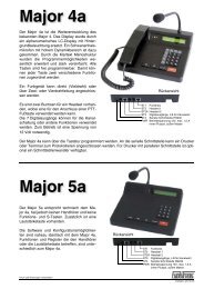
The <strong>Major</strong> <strong>4a</strong>/<strong>5a</strong> is the newer design of the well-known <strong>Major</strong> 4/5 An alphanumeric LC Display with<br />
background lighting has replaced the LED Display. A gooseneck microphone with a high dynamic<br />
range is part of the standard equipment of <strong>Major</strong> <strong>5a</strong> as well as <strong>Major</strong> <strong>4a</strong>. By using a plain text based<br />
menu structure the programmable features have been extended significantly and at the same time<br />
programming has become more straightforward. All buttons are freely programmable. Hence, each<br />
of the buttons can be assigned two different functions.<br />
A radio set can be connected directly (multiwire) or via 2- or 4-wire line. All viable tone sequences<br />
can be transmitted and interpreted.<br />
With the optional TIM (telephone interface module) a dial-up connection to the telephone network<br />
can be established. It can be used to forward a radio to the telephone network and also for remote<br />
control of radio sets via analogous land-line. To gain access to the radio a dial-up connection is established.<br />
<strong>Major</strong> <strong>4a</strong>/<strong>5a</strong> (if a TIM is included) can be ordered with a software option that enables the<br />
substitution of a permanent line by using a dial-up connection.<br />
There are two sockets for headsets. One can be used for a remote PTT foot switch. The 7 digital<br />
outputs can be used for remote channel select or for other functions. For operation an external 12volt<br />
power supply is necessary.<br />
The <strong>Major</strong> <strong>4a</strong>/<strong>5a</strong> can be programmed via the serial interface or keypad. It is also possible to connect<br />
a printer or a terminal to the serial interface. For printers with a parallel interface an additional<br />
interface is available.<br />
Kompetent für Elektroniksysteme<br />
- 4 -<br />
m<strong>4a</strong><strong>5a</strong>_v320_eng (14.02.2013)
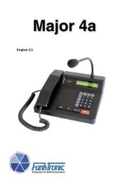
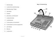
Control Elements <strong>Major</strong> <strong>4a</strong><br />
handpiece with<br />
PTT button<br />
m<strong>4a</strong><strong>5a</strong>_v320_eng (14.02.2013)<br />
gooseneck microphone<br />
status LEDs<br />
loudspeaker (LS)<br />
button<br />
Control Elements <strong>Major</strong> <strong>5a</strong><br />
gooseneck microphone<br />
loudspeaker<br />
volume button<br />
loudspeaker button<br />
short call button<br />
short call button<br />
call button<br />
call button<br />
- 5 -<br />
PTT button<br />
status LEDs<br />
PTT button<br />
LC display<br />
function buttons<br />
special buttons<br />
LC display<br />
Kompetent für Elektroniksysteme
Display Elements <strong>Major</strong> <strong>4a</strong> / <strong>5a</strong><br />
LC Display<br />
All alphanumeric readouts are presented by a LC display with background lighting.<br />
Status LEDs<br />
Carrier Display (Squelch)<br />
The carrier display LED can be controlled by voice (2-wire connection) or via squelch input<br />
(using the radio set). If the light is on, the radio circuit is occupied, that is, a carrier signal<br />
(carrier is keyed) is present.<br />
PTT Display (Push-to-Talk)<br />
The PTT display LED is on, if the transmitter is keyed. Keying of the transmitter is achieved<br />
by pressing the PTT button during telephony or by sending a call.<br />
Loudspeaker Display (Incoming Call)<br />
The loudspeaker display LED is on, if the loudspeaker or the earphone capsule in the<br />
handpiece are switched on.<br />
Keypad Layout <strong>Major</strong> <strong>4a</strong> / <strong>5a</strong> in Radio Mode<br />
Button <strong>Major</strong> <strong>4a</strong> <strong>Major</strong> <strong>5a</strong><br />
0 to 9 input of number to call input of number to call<br />
S1 to S4 no function not available<br />
* no function input of A<br />
# short: scroll ID-code memory short: scroll ID-code memory<br />
long: delete ID-code memory long: delete ID-code memory<br />
F4 switch on/off telephone mode not available<br />
PTT push-to-talk push-to-talk<br />
call button transmit call transmit call<br />
short call button transmit short call 0-9 transmit short call 0-9<br />
loudspeaker button short: loudspeaker on/off loudspeaker on/off<br />
long: adjust volume<br />
volume button not available adjust volume<br />
Kompetent für Elektroniksysteme<br />
- 6 -<br />
m<strong>4a</strong><strong>5a</strong>_v320_eng (14.02.2013)
General Handling<br />
Talking to the Radio<br />
There are two different ways to talk to the radio.<br />
By pushing the red PTT button the transmitter is switched on and the transmission LED is<br />
lit. This can also be achieved by an external PTT (see Connections). Now, talking to the radio is<br />
possible via the gooseneck microphone. After releasing the PTT button, the person on the radio<br />
can be heard in the loudspeaker. The loudspeaker LED is lit. If the conversation is finished, the<br />
loudspeaker can be switched off using the loudspeaker button<br />
The transmitter (and the transmission LED) can also be switched on by pushing the PTT button at<br />
the inside of the handpiece. Accordingly, the microphone and the loudspeaker of the handset are<br />
used for conversation in this case. The conversation is terminated by simply hanging up the handpiece.<br />
Switching of the Loudspeaker (on/off)<br />
The loudspeaker is switched on after sending a call by pushing the red or the external PTT button<br />
or upon reception of a call. However, it can also be activated manually via the loudspeaker button.<br />
The loudspeaker is switched off manually (loudspeaker button) or automatically after a certain time<br />
is elapsed. This loudspeaker timer is started when the loudspeaker is turned on and is reset as<br />
long as a carrier is present or PTT is keyed.<br />
If desired, this timer can also be disabled. Furthermore, the loudspeaker can be configured for<br />
open-mode („always-on“, see Table of Registers, Register 050).<br />
Volume Settings<br />
In order to set the desired volume the volume button is pushed (<strong>Major</strong> <strong>5a</strong>) or the loudspeaker<br />
button is pressed long (<strong>Major</strong> <strong>4a</strong>). The display now shows „volume:“ and the present value (0-9).<br />
Now the new volume can be set via the keypad. The chosen value is saved permanently (also<br />
after power-off).<br />
Short Call<br />
The <strong>Major</strong> can remember up to 10 short calls. These are transmitted by pushing the short call button<br />
followed by the respective number (0-9).<br />
These short calls are programmed in the registers 000 to 009 (see Table of Registers, Registers<br />
000-009)<br />
Call Options<br />
With the standard settings, „select number:“ followed by the previously transmitted call is displayed<br />
in the LCD. Of course, after power-on no number is displayed.<br />
In order to send a call the variable digits of the tone sequence (see Table of Registers, register<br />
010) first have to be entered. The tones entered via the keyboard are displayed right-justified in the<br />
LCD. The transmission of the call is achieved by pushing the call button . Alternatively, calls<br />
can be sent automatically after the last free number is entered (see Table of Registers, register<br />
082).<br />
m<strong>4a</strong><strong>5a</strong>_v320_eng (14.02.2013)<br />
- 7 -<br />
Kompetent für Elektroniksysteme
Programming Mode<br />
Keypad Layout of <strong>Major</strong> <strong>4a</strong> in Programming Mode<br />
The -button reduces by 1 und the -button<br />
increases by 1.<br />
To the buttons S1 to S4, * and # the values A<br />
bis F are assigned.<br />
Keypad Layout of <strong>Major</strong> <strong>5a</strong> in Programming Mode<br />
Long pressing of the buttons 1 to 6 allows to<br />
achieve the additional values A to F.<br />
The call button reduces by 1 and the PTT button<br />
increases by 1.<br />
Differences between <strong>Major</strong> <strong>4a</strong> and <strong>Major</strong> <strong>5a</strong><br />
<strong>Major</strong> <strong>4a</strong> and <strong>Major</strong> <strong>5a</strong> show the following differences:<br />
Kompetent für Elektroniksysteme<br />
- 8 -<br />
-<br />
+<br />
¡123 45 8<br />
0 9 7<br />
*<br />
6<br />
S1<br />
A<br />
¡<br />
#<br />
E F<br />
B<br />
S2<br />
¡ C<br />
S3<br />
¡ D<br />
S4<br />
123 45 8<br />
0 9 7<br />
*<br />
6<br />
A B C<br />
D E F<br />
#<br />
1. different keyboards<br />
2. <strong>Major</strong> <strong>4a</strong> includes a handset, <strong>Major</strong> <strong>5a</strong> does not<br />
3. minor differences in the software, resulting from 1. and 2.<br />
4. optional telephone interface only for <strong>Major</strong> <strong>4a</strong> (permanent line also <strong>Major</strong> <strong>5a</strong>)<br />
-<br />
+<br />
m<strong>4a</strong><strong>5a</strong>_v320_eng (14.02.2013)
Menu Structure<br />
Simultaneuos pressing of the buttons * and # opens the menu.<br />
Due to the different keypad designs, for the same operations different keys are used in <strong>Major</strong> <strong>4a</strong> and<br />
<strong>Major</strong> <strong>5a</strong>. In the following, the handling of <strong>Major</strong> <strong>4a</strong> is described. For the respective keys that have<br />
to be used in <strong>Major</strong> <strong>5a</strong> please consider the table below.<br />
Function <strong>Major</strong> <strong>4a</strong> <strong>Major</strong> <strong>5a</strong><br />
next menu *<br />
select menu item #<br />
escape discarding changes *<br />
save changes and escape #<br />
increase value by 1<br />
reduce value by 1<br />
select number:<br />
EEPROM programming : F4<br />
Next menu : F3<br />
Register:<br />
* and #<br />
È<br />
- enter the register number<br />
to be programmed<br />
- with 222 the factory default<br />
values are programmed<br />
Register: 000<br />
Code 12345<br />
- overwrite the code with the<br />
desired values<br />
m<strong>4a</strong><strong>5a</strong>_v320_eng (14.02.2013)<br />
Software Version : F4<br />
Next menu : F3<br />
Æ Æ<br />
Software: <strong>Major</strong> <strong>4a</strong> V1.24<br />
Date : 23.09.04<br />
*<br />
GN = gooseneck<br />
HP = handpiece<br />
HS = headset<br />
- 9 -<br />
Level settings : F4<br />
Next menu : F3<br />
È È È<br />
= escape menu<br />
discarding changes<br />
= save changes,<br />
escape menu<br />
- displayed 3 seconds<br />
Poti-Nr. (1-6):<br />
1 = input level<br />
nominal value: 300mV<br />
indicated on the display<br />
2 = output level<br />
as required<br />
3 = GN microphone level *<br />
4 = HA microphone level *<br />
5 = HS microphone level *<br />
6 = DTMF output level<br />
- the potis can be adjusted<br />
from 0 to 255<br />
- input directly via keypad<br />
or<br />
= increase value by 1<br />
= reduce value by 1<br />
= escape menu<br />
discarding changes<br />
= save changes,<br />
escape menu<br />
Kompetent für Elektroniksysteme
Menu Structure<br />
continued<br />
select number:<br />
0 = 200 Hz<br />
1 = 300 Hz<br />
2 = 400 Hz<br />
3 = 600 Hz<br />
4 = 800 Hz<br />
5 = 1000 Hz<br />
6 = 1600 Hz<br />
7 = 2400 Hz<br />
8 = 3400 Hz<br />
9 = 4000 Hz<br />
S1 = 2900 Hz<br />
S2 = 3000 Hz<br />
S3 = 3100 Hz<br />
S4 = 3300 Hz<br />
* = 1200 Hz<br />
# = 1800 Hz<br />
= escape menu<br />
Kompetent für Elektroniksysteme<br />
* and #<br />
È<br />
Æ Æ Æ<br />
Transmit test tone : F4<br />
Next menu : F3<br />
È<br />
Change frequency 0.....C<br />
F3 for ESC Hz<br />
Æ<br />
Adjust contrast : F4<br />
Next menu : F3<br />
È<br />
Display contrast: 90<br />
F1- F2+ F3ESC F4STORE<br />
= reduce contrast by 1<br />
= increase contrast by 1<br />
= escape menu<br />
discarding changes<br />
= save changes,<br />
escape menu<br />
- 10 -<br />
Æ<br />
Set date/time : F4<br />
Next menu : F3<br />
È<br />
15.10.04 22:47:01<br />
= one digit to the left<br />
= one digit to the right<br />
= escape menu<br />
discarding changes<br />
= save changes,<br />
escape menu<br />
The values can be changed<br />
directly using the buttons 0<br />
to 9.<br />
m<strong>4a</strong><strong>5a</strong>_v320_eng (14.02.2013)
Menu Structure<br />
continued<br />
select number:<br />
* und #<br />
È<br />
Æ Æ Æ<br />
Æ Æ Æ<br />
Adjust clock : F4<br />
Next menu : F3<br />
È<br />
Digital (0-6) : 3<br />
Analog (00-59): 29<br />
= one digit to the left<br />
= one digit to the right<br />
The onboard clock is factory<br />
calibrated. Before changing<br />
the values please note down<br />
the current values. Higher<br />
values accelerate the clock,<br />
while lower values slows<br />
it down. Changes made<br />
in digital have more effect<br />
than changes made in analog.<br />
Fine adjustment must<br />
be done in analog, step by<br />
step.<br />
= escape menu<br />
discarding changes<br />
= save changes,<br />
escape menu<br />
m<strong>4a</strong><strong>5a</strong>_v320_eng (14.02.2013)<br />
Æ<br />
Serial number : F4<br />
Next menu : F3<br />
- displayed for 3 seconds<br />
Serial number: 0123/06<br />
Mainboard: 0456/06<br />
- 11 -<br />
Kompetent für Elektroniksysteme
Programming Example<br />
Programming Short Call<br />
In the following a programming example of the <strong>Major</strong>‘s registers is shown. The procedure is always<br />
the same. Depending on the desired effects, however, the programming of several registers can be<br />
necessary.<br />
This example illustrates the programming of short call 1 in register 001 with the tone sequence<br />
12345.<br />
Please press the following buttons:<br />
select number:<br />
Switch to programming mode<br />
with * and #<br />
confirm EEPROM programming<br />
with F4.<br />
Register: 001 (keypad input)<br />
and<br />
input tone sequence: 12345<br />
The line „Code“ shows the present programming of the register. The displayed value can be overwritten<br />
with the new value.<br />
With button F3 the menu can be quit any time discarding the changes.<br />
With button F4 the displayed value is programmed.<br />
As every button of the <strong>Major</strong> <strong>4a</strong>/<strong>5a</strong> is freely programmable, the registers 174 and 175 for the Z-button<br />
have to be programmed with the right values. As this already is the case in the factroy defaults, this<br />
step is not necessary.<br />
Hence, register 174 (function Z-button, short press) usually is programmed with 22F01 and register<br />
175 (function Z-button, long press) with 00000. The first 0 in register 175 defines that no additional<br />
function of the button is exercised upon long pressing.<br />
Kompetent für Elektroniksysteme<br />
* and #<br />
È<br />
EEPROM programming : F4<br />
Next menu : F3<br />
Register:<br />
È<br />
0<br />
0<br />
1<br />
È<br />
Register: 001<br />
Code 12345<br />
- 12 -<br />
m<strong>4a</strong><strong>5a</strong>_v320_eng (14.02.2013)
Tone Call Encoder<br />
Transmitting 5-Tone Sequences<br />
For the transmission of 5-tone sequences it can be configured which tones are set by manual input<br />
and which ones are preset (see Table of Registers, register 010).<br />
Example: 5-tone sequence<br />
5-tone sequence with the following properties are to be sent:<br />
1 st digit: tone 9<br />
2 nd digit: tone 8<br />
3 rd digit: manual input via keypad<br />
4 th digit: tone 7<br />
5 th digit: manual input via keypad<br />
Register 010: 98F7F000 contains the tone sequence (digits 1-5).<br />
F allows for a manual input at the respective digit.<br />
Digits 6 and 7 are not in use and, hence, are set to zero. Digit 8 defines the type of the tone sequence,<br />
the ID-code. Here, zero stands for a 5-tone sequence.<br />
If all digits are coded with FFFFFFFF, the complete tone sequence has to be entered manually.<br />
If all digits are coded with EEEEEEEE, the manual input of numbers to call is turned off.<br />
Register 082: 07707000 is the factory default of the register.<br />
Digits 1 and 2 define the length of the first tone to 70ms.<br />
Digit 3 defines the length of all other tones to 70ms.<br />
Digits 4 and 5 define the length of a break to 70ms (no effect in this case).<br />
Digit 6 disables the automatic transmission of the call upon entering all required digits.<br />
Transmit 3-7-Tone Sequence<br />
The <strong>Major</strong> can transmit tone sequences of variable length. Therefor, different procedures exist to<br />
build the tone sequence.<br />
3-7-tone sequences are defined completely in register 010.<br />
Dazu wird die 8. Stelle des Registers auf 9 gesetzt.<br />
Free digits (manual input) are coded with F, digits that are not in use are coded with 0.<br />
The number of tones in the sequence is defined in register 081 (digit 6).<br />
Example: 7-tone sequence 123xx89<br />
7-tone sequence with two free digits (4 and 5).<br />
Register 010: 123FF899 defines the tone sequence.<br />
Digits 1-7 represent the tone sequence. The digits coded with F are entered via the keypad before<br />
transmission.<br />
Digit 8 defines the type of the tone sequence (ID-code), here: 3-7-tone sequence.<br />
Register 081: 01810700 digit 6 defines the length of the 3-7-tone sequence (here: 7 digits).<br />
Register 082: 07707000 is again set to the factory default (see section Transmitting 5-tone<br />
sequences).<br />
m<strong>4a</strong><strong>5a</strong>_v320_eng (14.02.2013)<br />
- 13 -<br />
Kompetent für Elektroniksysteme
Transmission of Double Sequences<br />
Double sequences can be transmitted as 3-7-tone double sequences (see 3-7-tone sequence).<br />
The number of tones is set in register 081 (digit 6).<br />
The break or an alternative coupling tone between the two tone sequences is programmed with<br />
the call button (register 172).<br />
The call is programmed in register 010, the own ID-code in register 015.<br />
The order of the sequences, call -> ID-code or ID-code -> call (ID mode), is defined in register 010<br />
(digit 8). 1: call first, then ID-code 2: ID-code first, then call<br />
Example: 5-tone double sequence with call and ID-code<br />
A call is to be sent as a 5-tone double sequence, consisting of call and the own ID-code. The<br />
5-tone sequence begins with 123, the last two digits can be entered via the keypad. The own IDcode<br />
is 12311 (see Table of Registers, register 015).<br />
Register 010: 123FF001 contains the tone sequence (digits 1-5).<br />
F (digits 4 und 5) stands for manually programmable digits.<br />
Digits 6 and 7 are not in use and, hence, set to 0.<br />
Digit 8 defines the type of the tone sequence. 1 stands for a double sequence with call first and<br />
then ID-code. The number of tones in every sequence is defined in register 081 (digit 6). The<br />
break between both tone sequences is programmed with the call button (see Table of Registers,<br />
register 172).<br />
Register 015: 12311000 The first 3 digits are usually coded as in register 010. However, if<br />
desired they can also be coded completely arbitrarily.<br />
The 1 in digit 4 and 5 corresponds to the own ID.<br />
Register 081: xxxxx5xx specifies 5-tone sequence.<br />
Register 082: 07707000 is again set to factory defaults (see section Transmitting 5-tone sequences).<br />
This time the time of the break will have an effect.<br />
Register 172: 2000F000 The programming of the call button decides whether both sequences<br />
are separated by a break or a coupling tone. Coding F into digit 5 activates the break.<br />
Kompetent für Elektroniksysteme<br />
- 14 -<br />
m<strong>4a</strong><strong>5a</strong>_v320_eng (14.02.2013)
Transmission of 6-, 7-, 8-Tone Sequences<br />
This is another possibility to transmit tone sequences of varying length (see Table of Registers, register<br />
010). The 6-,7-,8-tone sequences (register 010: digit 8 is coded with 3,4 or 5) are composed<br />
by a 5-tone sequence from register 010 and the additionally necessary digits from register 015.<br />
These additional digits correspond to the own ID-code. Hence, the tone sequence consists of the<br />
call plus the own ID-code (from register 015).<br />
The ID is always programmed in the digits 3, 4 and 5 of register 015.<br />
For a 6-tone call it is digit 5,<br />
for a 7-tone call digits 4 and 5<br />
and for an 8-tone call digits 3 to 5 are used.<br />
Example: 7-tone sequence 123xx89<br />
In this example a 5-one sequence with a two-digit ID-code (two free digits at positions 4 and 5)<br />
plus an own two-digit ID-code.<br />
Register 010 123FF004 contains three invariable digits of the tone sequence(digits 1 -3).<br />
Digits 4 and 5 can be freely set by manual input..<br />
Digits 6 and 7 are not in use and, hence coded as zero.<br />
Digit 8 is programmed with 4 and specifies a 7-tone sequence.<br />
Register 015 12389000 contains the own ID-code in digits 4 and 5.<br />
The first 3 digits are usually programmed according to the invariable digits of the tone sequence,<br />
however, they do not have any effect in this case.<br />
Register 082 07707000 is again set to the factory default (see section Transmitting 5-tone<br />
sequences).<br />
m<strong>4a</strong><strong>5a</strong>_v320_eng (14.02.2013)<br />
- 15 -<br />
Kompetent für Elektroniksysteme
Decoder<br />
<strong>Major</strong> <strong>4a</strong>/<strong>5a</strong> contains 10 decoders that are freely programmable by 3 registers for each of the decoders<br />
(see Table of Registers, registers 020-049). If the <strong>Major</strong> is set to factory defaults, an alarm<br />
tone signalizes a decoded call. Furthermore, the loudspeaker is activate, its LED flashes, the alarm<br />
output (switching output 7) is switched and the standard acknowledgement is sent (only decoder 0,<br />
all the others are not active).<br />
The corresponding registers:<br />
Register 020 - 029: tone sequences and activation/deactivation of the respective decoder<br />
Register 030 - 039: actions upon decing a call, alarm tone, volume<br />
Register 040 - 049: ID mode (type of tone sequence, call->ID-code / ID-code->call,...)<br />
switching outputs, loudspeaker, display, emergency call flag<br />
Every single decoder can be configured independently. Starting with decoder 1, the received tone<br />
sequence is compared to the stored tone sequence. If the sequence is recognized positively by the<br />
decoder, no further decoding of the other decoders is performed. If the tone sequence is not recognized<br />
by decoder 1 it is compared to the sequence stored in decoder 2. This routine is repeated for<br />
all decoders until decoding is successful or until comparison to the last decoder is performed.<br />
The alarm tone can be programmed separately for each decoder (see Table of Registers, registers<br />
030-039). The alarm tone is an alternating sequence of two tones with different frequencies. Upon<br />
calling the alarm tone can be set to a defined volume for a certain time. This can be an explicit<br />
value between 0 and 9 or a volume increase of 0 to 5 steps (programmed as A to F). The duration<br />
of the volume increase can be set from 0 to 3 s in 200 ms steps.<br />
Register 030 - 039<br />
1 st digit: alarm tone<br />
1 = 600/675Hz 6 = 1100/1375Hz<br />
2 = 800/900Hz 7 = 500/750Hz<br />
3 = 1000/1125Hz 8 = 1000/1500Hz<br />
4 = 700/875Hz 9 = 700/1283Hz<br />
5 = 900/1125Hz 0 = no alarm tone<br />
Kompetent für Elektroniksysteme<br />
B = 600/675Hz, 10 repetitions<br />
C = 800/900Hz, 10 repetitions<br />
D = 1000/1125Hz, 10 repetitions<br />
E = 700/875Hz, 10 repetitions<br />
F = 900/1125Hz, 10 repetitions<br />
2 nd digit: duration 0 to F: n* 200ms, corresponding to 0 to 3s<br />
3 rd digit: call volume 0 to 9: constant volume, A to F: volume increased by 0 to 5 steps<br />
- 16 -<br />
m<strong>4a</strong><strong>5a</strong>_v320_eng (14.02.2013)
Example 1: decode 5-tone sequence 9867x<br />
The first decoder is to decode the tone sequence 9867x, i.e., for the 5 th digit arbitrary tones should<br />
be accepted. The first decoder is programmed in registers 020, 030 and 040.<br />
Register 020 9867FFF1<br />
1 st - 4 th digit are the 4 invariable digits of the tone sequence (9867)<br />
5 th digit is arbitrary and hence coded with an F.<br />
6 th and 7 th digit are not in use. thus, they are both coded with F.<br />
8 th digit is set to 1 and activates the decoder.<br />
Register 030<br />
1 st digit: alarm tone type, e.g. 1<br />
2 nd digit: alarm tone duration in steps of n*200ms between 0 and 3s, e.g. A = 10 => 2s<br />
3 rd digit: alarm tone volume (constant volume: 0 - 9, A - F: increased by 0 to 5 steps,<br />
e.g. C => 2 steps louder<br />
4 th digit: duration of call volume<br />
5 th digit: call volume<br />
Register 040<br />
1 st digit is 0 (ID-Mode) for a 5-tone sequence with ID decoding, else 7<br />
2 nd digit: defines the correspondng switching contact, e.g. 7 => output 7 (0: no output)<br />
3 rd digit: switching time (n * 1s)<br />
4 th digit: acknowledgement, e.g. 4 as an acknowledgement for a received ID-code<br />
5 th digit: switch loudspeaker/LED, e.g. 1 for loudspeaker on, LED does not flash<br />
6 th digit: without effect for 5-tone sequences<br />
Register 016 9867FFFF<br />
1 st - 4 th digit: invariable digits of the tone sequence<br />
5 th digit takes an arbitrary value (coded with F) and hence causes the 1-digit ID-code<br />
to be displayed<br />
6 th - 8 th digit are not in use (coded with F)<br />
Example 2: decode 3-7-tone sequence with ID-code<br />
Decoder 2 (registers 21, 31, 41) is to decode the 7-tone sequence 1234589 (ID mode 9). The tone<br />
sequence is specified completely in register 021.<br />
Register 081 contains 7 for 7-tone sequence at digit 6.<br />
Register 021 coded with 12345891, 7-digit tone sequence, 8 th digit: 1 (decoder activation)<br />
Register 031 defines the reactions to an incoming call (see example 1)<br />
Register 041 contains the ID mode in digit 1 (here: 9), for further digits see example 1<br />
Register 016 e.g. 123458FF<br />
1 st - 6 th digit: invariable digits of the tone sequence<br />
7 th digit: arbitrary (F), hence 1-digit ID-code is displayed<br />
8 th digit not in use (F)<br />
m<strong>4a</strong><strong>5a</strong>_v320_eng (14.02.2013)<br />
- 17 -<br />
Kompetent für Elektroniksysteme
Example 3: decode double sequence<br />
In this example a 5-tone double sequence is to be decoded that consists of call and a following ID<br />
code. Decoding is performed in decoder 3 (registers 022, 032, 042).<br />
The invariable digits of the 5-tone sequence for the ID code usually is identical to the own ID code<br />
(as in register 015). The length of the tone sequence is stored in register 081, digit 6.<br />
Register 081 xxxxx5xx<br />
Register 022 contains the (own) call that is to be decoded, e.g. 12311FF1.<br />
Register 032 defines the reactions to an incoming call (see example 1).<br />
Register 042 contains the ID mode in digit 1 (here coded as 1), for further digits see example 1<br />
Register 016 e.g. 123FFFFF invariable digits: 123, followed by two-digit ID display FF, last three<br />
digits are not in use: FFF<br />
Example 4: decode 6-, 7-, 8-tone sequence<br />
The example shows a 7-tone sequence that is to be decoded by decoder 4 (registers 023, 033,<br />
043). The first 5 tones of the sequence to decode are defined in register 023. Depending on the<br />
chosen tone sequence (6-,7-, or 8-tone) the remaining tones are decoded as the ID code of the<br />
caller. The length of the tone sequence is defined in register 043 (ID mode).<br />
Register 023, e.g. 12311FF1 5-digit tone sequence, 8 th digit activates the decoder<br />
Register 033 defines the reactions to an incoming call (see example 1).<br />
Register 043 contains the ID mode in digit 1 (here coded as 4 => 7-tone sequence)<br />
For further digits see example 1.<br />
Kompetent für Elektroniksysteme<br />
- 18 -<br />
m<strong>4a</strong><strong>5a</strong>_v320_eng (14.02.2013)
ID code memory<br />
The key tones for ID decoding and ID code memory are programmed in register 016 for all<br />
decoders.<br />
The first 7 digits of register 016 contains the tone sequence that has to be decoded for the ID code<br />
memory. Arbitrary digits are coded with F, as well as the digits that are not in use.<br />
In register 086 the ID code memory is configured.<br />
The first digit activates/deactivates the update function. If update is activated and an ID code from<br />
the memory is decoded the old ID is deleted and the new one is stored in the respective position.<br />
The second digit activates/deactivates the FIFO mode (first in - first out). In FIFO mode the ID code<br />
that arrived first (i.e. the oldest one) is displayed.<br />
In the third digit it can be defined if an arriving ID code is displayed immediately or if it is to appear<br />
only after skimming to its position.<br />
Storing of ID codes from double sequences is done according to the decoder programming. The ID<br />
mode defines in which of 2 tone sequences the ID code is transmitted. It is then passed to the ID<br />
code memory.<br />
Example: 6-tone sequence 123x5x with 2-digit ID code in digits 4 and 6:<br />
Register 016 123F5FFF<br />
1 st - 3 rd and 5 th digit are invariable digits of the tone sequence<br />
4 th and 6 th digit can have arbitrary values and are coded with F<br />
7 th and 8 th digit are not in use and thus also coded with F<br />
Register 086 10100000<br />
1 st digit activates update mode<br />
2 nd digit deactivates FIFO mode<br />
3 rd digit = 1 defines that new ID codes are displayed immediatelay<br />
Muting 5-Tone Sequence<br />
Muting (register 018) is triggered by the first two tones and lasts until the end of the tone sequence.<br />
The first tone must be a valid tone in terms of duration. As soon as the second tone is recognized,<br />
handpiece and loudspeaker are muted. For digits that are programmed with ‘F‘, all tones are valid.<br />
To disable muting ‚EE‘ is programmed.<br />
m<strong>4a</strong><strong>5a</strong>_v320_eng (14.02.2013)<br />
- 19 -<br />
Kompetent für Elektroniksysteme
FFSK mode<br />
<strong>Major</strong> <strong>4a</strong> can be used in mixed networks, where FFSK and common tone sequence signalling<br />
(see Transmitting 5-Tone Sequences) are to be used simultaneously. Therefor, a FFSK-decoder/<br />
encoder is active in addition to the tone-decoder/encoder.<br />
Composition of a Telegram<br />
The call telegram starts with an unmodulated carrier that has to be present at the receiver for<br />
at least 25 ms. This is followed by a 16-bit digital sequence and the block synchronization. For<br />
block synchronization a 15-bit barker word with a preceding 1 is used. The following selective call<br />
consists of 8 digits:<br />
1 st digit: code of the mode of operation (CMO) (invariable)<br />
2 nd digit: status (invariable)<br />
3 rd digit: hash key identification (invariable)<br />
4 th +5 th digit: producer identification (variable)<br />
6 th -8 th digit: call (variable)<br />
Code of the Mode of Operation (CMO)<br />
The CMO distiguishes the different types of telegrams. The following types are supported by the<br />
<strong>Major</strong>:<br />
Nr. Meaning <strong>Major</strong><br />
0 available (free) (x)<br />
1 Q call to car x<br />
2 Q call to control center x<br />
3 ID code x<br />
4 acknowledgement x<br />
5 additional telegram<br />
6 Q cutting call<br />
7 reserve<br />
8 Q priority call<br />
9 Q status request<br />
A reserve<br />
B reserve<br />
C reserve<br />
D available (free)<br />
E available (free)<br />
F emergency call x<br />
CMOs marked with a Q require an acknowledgement. The CMO is programmed together with the<br />
PTT button at digit 5 (usually with ‘1’ => call to car, standard: call button, short press; see Table of<br />
Registers, register 172).<br />
The CMO for call decoding is programmed in register 091 (2 nd digit, usually programmed with ‘2’ =><br />
call to control center).<br />
Kompetent für Elektroniksysteme<br />
- 20 -<br />
m<strong>4a</strong><strong>5a</strong>_v320_eng (14.02.2013)
Status<br />
The status of the call is programmed in register 054 (digit 3). For decoding the status is not<br />
important. All values are accepted.<br />
Producer Identification and Call<br />
Digits 4 and 5 (producer identification) and 6-8 (call) are combined by the <strong>Major</strong> and treated like a<br />
5-tone sequence. Hence, call encoder and decoder are programmed in the same way as for the 5tone<br />
sequence.<br />
Hash Key Identification for Calls<br />
The 1-digit hash key identification is programmed in register 090 (digit 5). For decoding all values<br />
are accepted.<br />
Threshold Number<br />
While 5-tone-decoder and FFSK-decoder are active simultaneously, it has to be decided before a<br />
call if a 5-tone-telegram or an FFSK telegram is to be sent. The decision depends on the value of<br />
the call (three last numbers of the FFSK telegram). Below a certain threshold number one telegram<br />
type is used, aboce this number the other is used.<br />
The threshold number is set in register 090 (digits 1-3). The 4 th digit defines if a FFSK or tone<br />
sequence is used below the threshold number. If it is coded with 0, FFSK is used below the<br />
threshold number and starting with the threshold number tone sequences are used. The reverse<br />
case is achieved by programming ‘1’.<br />
Example 1:<br />
Below the threshold number 51 tone sequences are to be sent, while FFSK signals should be sent<br />
above it.<br />
Register 090 0511xxxx contains the threshold number 051 and a ‘1’ at digit 4 to enable FFSK<br />
starting at the threshold number.<br />
Example 2:<br />
If only FFSK signals are to be sent, the threshold value is set to ‘000’ and digit 4 is set to ‘1’.<br />
Register 090 0001xxxx<br />
Example 3:<br />
Only tone sequences are sent. Threshold number is again set to ‘000’, but this time digit 4 is set to<br />
‘0’.<br />
Register 090 0000xxxx (factory default)<br />
m<strong>4a</strong><strong>5a</strong>_v320_eng (14.02.2013)<br />
- 21 -<br />
Kompetent für Elektroniksysteme
FFSK Encoder<br />
The 5 digits of the producer identification and the call (4 th - 8 th digit in the 8-digit FFSK telegram)<br />
are treated in the same way as for 5-tone telegrams. The digits that should not be entered via the<br />
keypad are invariably coded. Invariable digits can be located anywhere throughout these 5 digits.<br />
Hence, it is also possible to invariably set digits 4, 6 and 8 of the FFSK telegram. In this case,<br />
digits 5 and 7 areentered via the keypad. Usually, the first 2 digits (producer indentification) or the<br />
first 3 digits (producer identification and first digit of the call) are preset. The digits that are to be<br />
entered by the keypad are always displayed right-justified. The encoder is programmed in register<br />
010 (see section Transmitting of 5-Tone Sequences).<br />
FFSK Decoder<br />
For all telegrams the CMO is checked. If the CMO is consistent with register 091 (digit 2), the<br />
encoder is activated. The encoders are coded in registers 020-029, 030-039 and 040-049 (see<br />
Table of Registers). The recognized telegram is compared to the decoder values, accepting<br />
all values at digits that are programmed with an ‘F’. After a positively recognized telegram, the<br />
loudspeaker and the earphone are switched on, the loudspeaker display flashes, depending on<br />
the settings the FFSK acknowledgement is sent and the alarm tone is activated. An additional<br />
comparison to other decoders is not performed.<br />
Kompetent für Elektroniksysteme<br />
- 22 -<br />
m<strong>4a</strong><strong>5a</strong>_v320_eng (14.02.2013)
Individual Programming of the Buttons<br />
All buttons of the <strong>Major</strong> <strong>4a</strong>/<strong>5a</strong> are freely programmable. The numeric keys, the * and # keys as<br />
well as the function buttons for volume (only <strong>Major</strong> <strong>5a</strong>), loudspeaker, short call, call and PTT are<br />
programmed ex factory for the respective tasks.<br />
Every button can be assigned two different functions. One is achieved by pressing the button<br />
shortly and the other by pressing it for a longer time.<br />
If the button is pressed for less than second, the function programmed for „short press“ is<br />
executed. For longer pressing the function programmed for „long press“ is executed. If no function<br />
is programmed for long press, the „short press“ function is executed immediately.<br />
Programming of the button‘s functions is done in registers 130-179. For every button 2 registers<br />
are reserv ed, the first onie for short press, the second one for long press (see Table of Registers,<br />
registers 130-179).<br />
The function of the LEDs in buttons F1 to F4 is defined in registers 180-183.<br />
Every register contains 8 digits. the first digit chooses the desired, the second digit chooses a<br />
subfunction (if necessary). The following digits specify the settings necessary for the respective<br />
function.<br />
The following functions are available:<br />
0: no function<br />
m<strong>4a</strong><strong>5a</strong>_v320_eng (14.02.2013)<br />
1: transmit single tone<br />
2: transmit call<br />
0: transmit entered call<br />
1: transmit callback<br />
2: transmit short call<br />
3: transmit Intercom<br />
4: transmit external short call<br />
5: transmit channel remot call<br />
3: PTT<br />
4: volume<br />
0: loudspeaker on/off<br />
1: volume<br />
2: loudspeaker on/off in telephone mode<br />
5: channel selection / switching outputs<br />
2/3: channel 00 -99<br />
2: E => configure switching outputs<br />
6: ID-code memory / call number memory<br />
in normal mode: edit ID-code memory / decoder<br />
in telephone mode: edit call number memory<br />
7: call number / tone input<br />
in normal mode: input of tones<br />
in telephone mode: input of call numbers<br />
8: status input<br />
in normal mode: status input<br />
in telephone mode: input of telephone status<br />
- 23 -<br />
Kompetent für Elektroniksysteme
Kompetent für Elektroniksysteme<br />
9: ext. inputs<br />
0: squelch input<br />
1: external muting<br />
B: mode functions<br />
0: activate normal mode<br />
1: activate telephone mode<br />
F: standby<br />
Example 1: Programming „short press“ of Buttons<br />
As an example, the functions for „short press“ of the buttons , and are programmed. In<br />
this case the buttons are programmed for channel selection.<br />
chooses channel 01<br />
chooses channel 02<br />
channel number must be entered via the keypad<br />
Programming of button short register 162<br />
funktion channel selection: 1 st digit: 5<br />
channel number 1: 2 nd digit: 0<br />
channel number 2: 3 rd digit: 1<br />
Digits 4-8 are not in use in this case.<br />
Stepwise programming of :<br />
Start Register Programming Finish Programming / Save<br />
select number:<br />
* and #<br />
È<br />
EEPROM programming : F4<br />
Next menu : F3<br />
Register:<br />
È<br />
1 62<br />
È<br />
Register: 162<br />
Code 50100000<br />
- 24 -<br />
È<br />
Register: 162<br />
EEPROM programmed<br />
Register:<br />
È<br />
È<br />
Funk Tronic <strong>Major</strong> <strong>4a</strong><br />
select number:<br />
m<strong>4a</strong><strong>5a</strong>_v320_eng (14.02.2013)
Buttons and are programmed analogously:<br />
Programming of button short register 164<br />
function channel selection: 1 st digit: 5<br />
channel number 1: 2 nd digit: 0<br />
channel number 2: 3 rd digit: 2<br />
Digits 4-8 are not in use.<br />
Programming of button short register 166<br />
function channel selection: 1 st digit: 5<br />
channel number 1: 2 nd digit: F (entered via keyboard)<br />
channel number 2: 3 rd digit: F (entered via keyboard)<br />
Digits 4-8 are not in use.<br />
Example 2: Programming the LEDs of buttons and<br />
If the respective channel is activated by one of the buttons, the LED is to be lit.<br />
Programming of the LED in button register 180<br />
channel display: 1 st digit: 2<br />
channel number 1: 2 nd digit: 0<br />
channel number 2: 3 rd digit: 1<br />
Programming of the LED in button register 181<br />
channel display: 1 st digit: 2<br />
channel number 1: 2 nd digit: 0<br />
channel number 2: 3 rd digit: 1<br />
Stepwise programming of the LED in button :<br />
m<strong>4a</strong><strong>5a</strong>_v320_eng (14.02.2013)<br />
Start Register Programming Finish Programming / Save<br />
select number:<br />
* and #<br />
È<br />
EEPROM programming : F4<br />
Next menu : F3<br />
Register:<br />
È<br />
1 80<br />
È<br />
Register: 180<br />
Code 20100000<br />
- 25 -<br />
È<br />
Register: 180<br />
EEPROM programmed<br />
Register:<br />
È<br />
È<br />
Funk Tronic <strong>Major</strong> <strong>4a</strong><br />
select number:<br />
Kompetent für Elektroniksysteme
Inputs / Outputs<br />
The in/outputs are configured in registers 096 and 097.<br />
Ex factory both registers are set as follows:<br />
register 096 11111000 programs the I/Os 1-5 as output, not inverted<br />
register 097 11100000 programs the I/Os 6-8 as output, not inverted<br />
The outputs are open collector circuits. They can be configured as follows:<br />
- 1 not inverted, passive state: switch is open, active: switches to GND<br />
- 8 outside switching, is input and not inverted output, simultaneously<br />
the state of the input can be read out, so that a switching state imposed on<br />
the I/O from an external source can be interpreted.<br />
- 9 inverted, passive state: switches to GND, active: switch is open<br />
If a connection is to be configured as input, the respective digit has to be coded with<br />
- 2: input is low-active, i.e. is switched to GND<br />
- 3: input is high-active, i.e. is switched to +batt<br />
Inputs can be assiged different functions. Therefor, it has to be decided, if the input is switched on<br />
or off.<br />
Example: Cross-Mute function<br />
If two <strong>Major</strong> <strong>4a</strong>/<strong>5a</strong> control sets are situated next to each other it might be desired to mute the<br />
loudspeaker of the respective inactive <strong>Major</strong>. Hence, if one <strong>Major</strong> is used for conversation, the<br />
other one is muted.<br />
Therefor, I/O pin 2 is to be used. As the inputs are to be switched as well as read out, it is necessary<br />
to configure the I/O for outside switching:<br />
Register 095 18111000 2 nd digit: 8, I/O 2 is configured for outside switching.<br />
For the muting the function radio-mute (see Table of Registers, register 083)is used.<br />
Register 083 22000000 Digit 1defines I/O pin 2 as muting output, the 2 nd digit configures the<br />
output to low-active and activates it only during transmission (TX or PTT is pressed).<br />
Now, the function for external muting still has to be programmed for I/O pin 2 (see Table of Registers,<br />
function 9). For I/O pin 2 this is done in register 112/113.<br />
Register 112 91110000 function 9 (digit 1) with subfunction 1 (digit 2) stands for external muting.<br />
The ‘1‘ at digit 3 activates muting if input 2 is activated. The ‘1‘ in digit 4 causes flashing of the<br />
PTT button if the input is activated from outside.<br />
Register 113 91000000 function 9 (digit 1) with subfunction 1 (digit 2: external muting) disables<br />
the muting and flashing again if input 2 is back to the inactive status (‘0‘ in digit 3)<br />
Both I/Os have to be connected to each other. The easiest way to do this is the use of an ordinary<br />
patch cable (if no other I/O-Pins are in use) to connect the I/O sockets of both <strong>Major</strong>s.<br />
Kompetent für Elektroniksysteme<br />
- 26 -<br />
m<strong>4a</strong><strong>5a</strong>_v320_eng (14.02.2013)
Alarm Signals FT63<strong>4a</strong>C => <strong>Major</strong> <strong>4a</strong>/<strong>5a</strong><br />
Up to 3 alarms can be transmitted from an FT63<strong>4a</strong>C to a <strong>Major</strong> <strong>4a</strong>/<strong>5a</strong>. The FT63<strong>4a</strong>C transmits<br />
transmits any change of the alarm switching contacts to the major immediately. If no acknowledgement<br />
is received, 3 repetitions are transmitted. If again no acknowledgement was received, transmission<br />
is retried after a minute.<br />
The <strong>Major</strong> displays each new alarm immediately. The operator has to acknowledge the alarms with<br />
the #-button. All received alarms are displayed until they are acknowledged, even if they are not<br />
active any more. In this case the present alarm status is displayed after the operator‘s acknowledgement<br />
and also has to be acknowledged.<br />
FT63<strong>4a</strong>C:<br />
Register 095: configuration for I/O 0-7 (0=output, 1=input)<br />
Register 096: configuration for I/O 8-15 (0=output, 1=input)<br />
Register 104: digits 1-4: alarm switching tone sequence (ABC0)<br />
digit 5: send alarm tone sequence without active alarms if already begun y/n (1/0)<br />
Register 108: function I/O 0 passive=>active (high=>low)<br />
Register 109: function I/O 0 active=>passive (low=>high)<br />
...<br />
Register 124: function I/O 8 passive=>active (high=>low)<br />
Register 125: function I/O 8 active=>passive (low=>high)<br />
...<br />
Register 138: function I/O 15 passive=>active (high=>low)<br />
Register 139: function I/O 15 active=>passive (low=>high)<br />
Function alarm input (has to be programmed into the respective register 108-139)<br />
1 st digit: 2: function alarm input<br />
2 nd digit: 0: emergency power input, 1:housebreaking input, 2:alarm input<br />
3 rd digit: 0: alarm off, 1: alarm active<br />
Standard programming for alarm transmission:<br />
Register 096: 111xxxxx (I/O 8,9,10 are inputs)<br />
Register 104: ABC01xxx (transmits alarm notification ABC0x when set active)<br />
Register 124: 201xxxxx I/O 8: emergency power input low: active<br />
Register 125: 200xxxxx I/O 8: emergency power input high: off<br />
Register 126: 211xxxxx I/O 9: housebreaking input low: active<br />
Register 127: 210xxxxx I/O 9: housebreaking input high: off<br />
Register 128: 221xxxxx I/O 10: alarm input low: active<br />
Register 129: 220xxxxx I/O 10: alarm input high: off<br />
m<strong>4a</strong><strong>5a</strong>_v320_eng (14.02.2013)<br />
- 27 -<br />
Kompetent für Elektroniksysteme
<strong>Major</strong> <strong>4a</strong>/<strong>5a</strong>:<br />
Register 075: digit 1-4: tone sequence for alarm notification (ABC0)<br />
digit 5: PTT for acknowledgement/request<br />
5 = with pilot-tone<br />
6 = without pilot-tone<br />
7 = without pilot-tone, without TX<br />
Register 076: configuration for alarm decoder<br />
digit 1: type of alarm tone<br />
digit 2: duration of alarm tone: n*200ms<br />
digit 3: alarm tone volume<br />
Register 077: configuration 2 for alarm decoder<br />
digit 1: request at power-on y/n (1/0)<br />
digit 2: number of switching output: 0 (none), 1-7<br />
digit 3: switching output: 0(off),F(on), time is variable: 1...E(14) seconds<br />
digit 4: acknowledgement: yes/no (1/0)<br />
digit 5: display time 1-F = 1-15s, 0 = ends with acknowledgement (#-button)<br />
It is also possible to program a button, so that an alarm query is sent to the FT63<strong>4a</strong>C Line Interface.<br />
Function 2 (transmit call):<br />
2 nd digit: 6: transmit alarm query<br />
Kompetent für Elektroniksysteme<br />
- 28 -<br />
m<strong>4a</strong><strong>5a</strong>_v320_eng (14.02.2013)
Reset to Factory Defaults<br />
Using the following steps, <strong>Major</strong> <strong>4a</strong> can be reset to factory defaults.<br />
Attention! All parameters are reset to the default values without further confirmation.<br />
Channel Scanning Function<br />
The channel scanning function is activated if the waiting time in register 067/5 is programmed NOT<br />
to be zero. Zero deactivates this function. The scanner will wait for at least the programmed waiting<br />
time per channel. Just before the end of the waiting time, the channel is checked for a carrier. If no<br />
carrier is detected the next channel will be scanned. Scanning will stop when a carrier is detected if<br />
“scanner stops on carrier“ (register 068/1) is programmed. If not the scanner will be stopped for at<br />
least 100 ms. During this time the scanner will scan for a tone. If a tone is detected, the scanner will<br />
wait for the scanner waiting time (068/2+3). If a call is decoded during that time the scanner stops.<br />
Otherwise the next channel is scanned.<br />
The channel range programmed in register 067/1-4 will be scanned. If register 067/1+2 is<br />
programmed with ‘EE’ the specified channels programmed in register 070-074 (EEPROM table) will<br />
be scanned. Scanning the table can be aborted by ‘FF‘.<br />
In order to scan channels 1, 5 and 6, register 070 is programmed with 0105xxxx and register 071<br />
with 06FFxxxx.<br />
After decoding a call the scanner stops for the programmed loudspkeaker time (050/1-3) which is<br />
retriggered by a carrier and/or PTT. Furthermore, the scanner can be switched off by activating the<br />
loudspeaker (LS button) manually.<br />
Scanning can be initiated by hanging up the handpiece (050/5). The scanner can also be activated<br />
using the “loudspeaker off” function (function 4; second digit: 0).<br />
Option FMS<br />
The FMS option allows for the status input and the reception of orders according to the German<br />
Funkmeldesystem (FMS).<br />
As for this option buttons 0-9 are used as status buttons, manual selection of a 5-tone sequence is<br />
not possible.<br />
m<strong>4a</strong><strong>5a</strong>_v320_eng (14.02.2013)<br />
select number:<br />
* and #<br />
È<br />
EEPROM programming : F4<br />
Next menu : F3<br />
Register:<br />
È<br />
2 22<br />
È<br />
program EEPROM with<br />
default values<br />
select number:<br />
- 29 -<br />
When entering register 223 the potentiometers<br />
are also reset to factory defaults.<br />
Kompetent für Elektroniksysteme
Rearview <strong>Major</strong> <strong>4a</strong>/<strong>5a</strong><br />
PWR<br />
PWR operating voltage 12V, max. 1,5 A<br />
inside: positive terminal, outside: GND<br />
Pinout S/E<br />
Radio Circuit (ST1)<br />
Pinout I/O<br />
Digital In/Outputs (ST3)<br />
IN/OUT 0 1<br />
IN/OUT 1 2<br />
IN/OUT 2 3<br />
IN/OUT 3 4<br />
IN/OUT 4 5<br />
IN/OUT 5 6<br />
IN/OUT 6 7<br />
GND 8<br />
Kompetent für Elektroniksysteme<br />
ST4 ST3 ST2<br />
AF input B 1<br />
AF input A 2<br />
Squelch input 3<br />
GND 4<br />
output +12 V, max. 200 mA 5<br />
PTT active, low 6<br />
AF output A 7<br />
AF output B 8<br />
ST2A<br />
Sockets Pinout <strong>Major</strong> <strong>4a</strong>/<strong>5a</strong><br />
ST1<br />
All of the schemes show the sockets as viewed from the rear of the <strong>Major</strong>.<br />
All AF in/outputs are equipped with transformers<br />
and, hence, potential-free. PIN 5 is for supply<br />
(+12V) of external devices (LIM-AC, FT634C).<br />
Attention: Do not use PIN 5 to supply a radio<br />
set. 200 mA output current is not sufficient.<br />
The digital connections can be configured as<br />
inputs or outputs, respectively. Usually, these are<br />
- 30 -<br />
There are two sockets for connecting a headset.<br />
One is for connecting the headset, the other<br />
for the use of an external PTT button (e.g. foot<br />
switch)<br />
Pinout HS<br />
Headset (ST2A)<br />
GND 1<br />
AF input (mic. +) 2<br />
AF earphone 3<br />
GND earphone 4<br />
GND AF input (mic. -) 5<br />
PTT, active GND 6<br />
Pinout PTT<br />
Headset (ST2)<br />
GND 1<br />
GND AF input (mic. -) 2<br />
NF earphone 3<br />
GND earphone 4<br />
AF input (mic. +) 5<br />
PTT, active GND 6<br />
Pinout RS232<br />
(ST4)<br />
NC 1<br />
NC 2<br />
TxD 3<br />
RxD 4<br />
GND 5<br />
NC 6<br />
used as outputs for remote channel select. To socket RS232 a printer can be connected.<br />
m<strong>4a</strong><strong>5a</strong>_v320_eng (14.02.2013)
RS232 Interface<br />
m<strong>4a</strong><strong>5a</strong>_v320_eng (14.02.2013)<br />
5 GND<br />
ST4 RS232 Interface<br />
RS232 Cable for Flashing/Printing/Monitoring<br />
RS232 25pin connector on computer RS232 socket on <strong>Major</strong><br />
2 TxD RS232<br />
3 RxD RS232<br />
7 GND<br />
2 RxD RS232<br />
3 TxD RS232<br />
Pinout<br />
RS232 ST4<br />
TxD<br />
RxD<br />
GND<br />
- 31 -<br />
1<br />
2<br />
3<br />
4<br />
5<br />
6<br />
Configuration of the RS232 Interface<br />
9600 Baud, 8 data bits, no parity, 1 stop bit, no protocol<br />
RS232 9pin connector on computer RS232 socket on <strong>Major</strong><br />
Pinout<br />
RS232 ST4<br />
TxD<br />
RxD<br />
GND<br />
1<br />
2<br />
3<br />
4<br />
5<br />
6<br />
Kompetent für Elektroniksysteme
Sample Configurations <strong>Major</strong> <strong>4a</strong>/<strong>5a</strong><br />
The following situation shows the easiest way for remote radio control using a <strong>Major</strong> <strong>4a</strong>/<strong>5a</strong>. If a remote control<br />
is not required, a 7-wire line is sufficient for AF, squelch and PTT.<br />
Kompetent für Elektroniksysteme<br />
7 AF, squelch, PTT<br />
max. 8 channel remote control<br />
- 32 -<br />
(7 Bit + GND)<br />
Sample Configurations <strong>Major</strong> <strong>4a</strong>/<strong>5a</strong>, DC controlled<br />
If only a local 2-wire line is available the following set-up using a DC line interface FT630-2 is recommended.<br />
In this configuration remote channel select and duplex mode are not possible.<br />
Several control panels in parallel circuit<br />
2<br />
2<br />
2<br />
FT624<br />
2<br />
2<br />
FT630-2<br />
without remote channel control<br />
2<br />
FT630-2<br />
without remote<br />
channel control<br />
m<strong>4a</strong><strong>5a</strong>_v320_eng (14.02.2013)
Example for duplex mode with 4-wire transmission<br />
m<strong>4a</strong><strong>5a</strong>_v320_eng (14.02.2013)<br />
2 x FT630-2, only if carrier<br />
signaling is to be transmitted!<br />
2<br />
2<br />
Sample Configurations <strong>Major</strong> <strong>4a</strong>/<strong>5a</strong>, AC controlled<br />
FT63<strong>4a</strong>C oder<br />
LIM-AC (only 2-wire)<br />
LIM AC<br />
LIM AC<br />
2<br />
2 or 4<br />
- 33 -<br />
FT63<strong>4a</strong>C (with remote channel control) or<br />
FT634 (without remote channeln control)<br />
Several control panels in parallel circuit --> LIM AC has to be equipped with a notchfilter to suppress<br />
the PTT keying tone. LIM AC is employed for rather long or rented lines.<br />
2<br />
2<br />
2<br />
FT624<br />
2<br />
2<br />
2<br />
FT630-2, only if carrier<br />
signalingis to be transmitted!<br />
FT630-2<br />
without remote channel control<br />
FT63<strong>4a</strong>C (with remote channel control) or<br />
FT634 (without remote channel control)<br />
Kompetent für Elektroniksysteme
Sample Configurations with Telephone Interface<br />
<strong>Major</strong> <strong>4a</strong> can be equipped with an optional telephone interface. Now the major can be connected to<br />
to the telephone network or an interphone system via an ordinary (analogous) telephone connection.<br />
This is achieved with a common RJ11 telephone socket at the rear of <strong>Major</strong> <strong>4a</strong>. Now, the following<br />
additional features are available:<br />
- dial switching of telephone connections to radio (manually or automatically)<br />
- dial switching of a radio connection to a telephone subscriber (manually or automatically)<br />
- connection of distant radio sets via analogous land-line. (with FT635 ÜLE, substitution of a<br />
permanent line)<br />
Dial switching to the telephone network (only <strong>Major</strong> <strong>4a</strong>)<br />
<strong>Major</strong> <strong>4a</strong> 8<br />
/<br />
<strong>Major</strong> <strong>4a</strong><br />
Kompetent für Elektroniksysteme<br />
telephone<br />
line<br />
2<br />
/<br />
telephone<br />
line<br />
2<br />
/<br />
telephone system or<br />
switching center / tel. network<br />
Remote control of a distant radio (pseudo-permanent line, <strong>Major</strong> <strong>4a</strong> and <strong>Major</strong> <strong>5a</strong>)<br />
telephone system or<br />
switching center / tel. network<br />
telephone<br />
line<br />
2<br />
/<br />
- 34 -<br />
telephone<br />
line<br />
2<br />
/<br />
FT635 ÜLE SL<br />
telephone<br />
Remote control of a distant radio is achieved using an FT635 ULE SL. For this configuration a telephone<br />
connection, of course, must also be present at the location of the radio.<br />
Basically, the ÜLE SL establishes a telephone connection, that is maintained for the desired time. Both<br />
devices monitor the status of the connection and rebuild the connection, if it was disconnected.<br />
8<br />
/<br />
radio<br />
radio<br />
m<strong>4a</strong><strong>5a</strong>_v320_eng (14.02.2013)
Hardware Configuration<br />
Two/Four-Wire Configuration<br />
The <strong>Major</strong> <strong>4a</strong>/<strong>5a</strong> can be configured for 2-wire and 4-wire connection. Starting with software version<br />
2.0 switching from 2-wire to 4-wire is done by programming register 051/4.<br />
Two-Wire Connection using FT630<br />
Over longer distances the radio set can be controlled via a 2-wire line. If PTT is keyed at the <strong>Major</strong>, a<br />
DC voltage is applied to the line in addition to the audio signal. This voltage is analyzed in the FT630-<br />
2 and the PTT relay turns on the transmitter. In the reverse situation the FT630-2 is able to apply a<br />
DC voltage to the line if an incoming signal (squelch) is present.<br />
If the DC voltage is used for transmitter keying as well as for detection of an incoming signal, no<br />
transmission is possible while a squelch signal is detected.<br />
Instead of the FT630-2 (DC) the line interfaces FT63<strong>4a</strong>C or FT634 can also be used. For these no<br />
DC coupling is necessary and additional features are available, e.g. the transmission via digital in-<br />
/outputs (alarm in case of dysfunction, housebreaking, fire...) and remote channel control.<br />
Register 069/1 defines if PTT keying is conducted by the PTT keying tone or by a DC voltage.<br />
m<strong>4a</strong><strong>5a</strong>_v320_eng (14.02.2013)<br />
- 35 -<br />
Kompetent für Elektroniksysteme
Connecting <strong>Major</strong> <strong>4a</strong>/<strong>5a</strong> --> Two-Way-Radio via Multiwire<br />
All audio in/outputs of the <strong>Major</strong> <strong>4a</strong>/<strong>5a</strong> are equipped with transformers and hence are potential-free.<br />
If no potential-free in/outputs are available at the radio, in both cases one of the audio connections<br />
has to be grounded, preferably by connecting pins 1 and 8 to GND pin 4. Switching from 2- to 4-wire<br />
is carried out by programming register 051/4.<br />
PIN 5 is for supply (+12V) of external devices (LIM-AC, FT63<strong>4a</strong>C).<br />
Attention: Do not use PIN 5 to supply a radio set. 200 mA output current is not sufficient.<br />
Connecting <strong>Major</strong> <strong>4a</strong>/<strong>5a</strong> --> LIM-AC<br />
The LIM-AC can be connected to <strong>Major</strong> <strong>4a</strong>/<strong>5a</strong> with a 8-terminal line. Commercially available computer<br />
cables may be used. For this, <strong>Major</strong> <strong>4a</strong>/<strong>5a</strong> must be set to 4wire mode (factory default in reg. 051/4)<br />
Kompetent für Elektroniksysteme<br />
- 36 -<br />
m<strong>4a</strong><strong>5a</strong>_v320_eng (14.02.2013)
Telephone Interface<br />
A <strong>Major</strong> <strong>4a</strong>/<strong>5a</strong> with telephone interface is able to perform the following operations:<br />
- control a distant radio set via a FT635ÜLE SL module (pseudo-permanent line)<br />
only <strong>Major</strong> <strong>4a</strong><br />
- dial switching of telephone connections to radio (manually oder automatically)<br />
- dial switching of a radio connection to a telephone subscriber (manually or automatically)<br />
- calls to the conventional telephone network<br />
Connection to the telephone network:<br />
With the telephone interface the an additional RJ11 socket is present at the <strong>Major</strong>. This<br />
socket is used for connection to the telephone network with a common telephone cable.<br />
Socket Pinout RJ11 (telephone)<br />
m<strong>4a</strong><strong>5a</strong>_v320_eng (14.02.2013)<br />
telephone<br />
1<br />
2<br />
Tip (a) 3<br />
Ring (b) 4<br />
5<br />
6<br />
- 37 -<br />
Kompetent für Elektroniksysteme
Handling of the Component Group<br />
The telephone interface consists of the carrier board and the attached TIM module.<br />
Please pay attention to the orientation while mounting the TIM, so that the connectors are not<br />
confused.<br />
The gap at the upper left corner of the TIM has to be directly above that of the carrier board. The<br />
edge-on view shows the positions of the connectors.<br />
An additional oblique view further illustrates the setting.<br />
Kompetent für Elektroniksysteme<br />
- 38 -<br />
m<strong>4a</strong><strong>5a</strong>_v320_eng (14.02.2013)
The telephone interface, built into the <strong>Major</strong>:<br />
m<strong>4a</strong><strong>5a</strong>_v320_eng (14.02.2013)<br />
- 39 -<br />
Kompetent für Elektroniksysteme
Telephone Mode (optional)<br />
<strong>Major</strong> <strong>4a</strong> can be used for manual and automatic switching between radio and telephone network.<br />
Therefor, it has to be furnished with the option telephone interface.<br />
Connection and Dial-Mode<br />
The connection to the telephone network is, as usually, established with a telephone cable with<br />
RJ11 plugs. The dial-mode is programmed in register 366:<br />
Reg. Function<br />
366 4 th digit<br />
0 = pulse dial<br />
1 = DTMF<br />
Switching from Radio Mode to Telephone Mode<br />
Button F4 activates the telephone mode (do not delete last number, forwarding options<br />
unchanged).<br />
Keypad Layout in Telephone Mode<br />
F1 short: forward toggle telephone (on/off)<br />
F4 short: start radio mode - does not delete last number - telephone on hold<br />
0 - 9 short: Input telephone number 0 - 9<br />
0 - 9 long: Input space ,* ,# ,A ,B ,C ,D ,/ ,- ,_<br />
S1 - S4 short: read out call number memory registers 001 - 004<br />
* short: previously dialed number<br />
# short: delete last digit of input<br />
# long: delete input completely<br />
PTT talking with the gooseneck microphone<br />
Call short: button for dialing, call reception and hanging up - does not change loudspeaker<br />
Z short: read out entered (0 - 999) or next call number from register<br />
Z long: program entered call number to memory (press twice)<br />
LS short: toggle loudspeaker - does not hang up telephone<br />
LS long: volume<br />
Connection Types<br />
Establishing a connection from the telephone to the radio can be achieved in 3 different ways:<br />
- Either the telephone call arrives at the control set and can be forwarded manually to the<br />
radio or<br />
- the incoming call is forwarded automatically to a preset radio participant or<br />
- the incoming call is forwarded automatically via DTMF to the desired radio participant.<br />
Kompetent für Elektroniksysteme<br />
- 40 -<br />
m<strong>4a</strong><strong>5a</strong>_v320_eng (14.02.2013)
Telephone Mode (optional)<br />
The operator of the <strong>Major</strong> <strong>4a</strong> can initiate and receive phone calls at any time (given that no automatically<br />
established connection exists already).<br />
Initiate Call button<br />
m<strong>4a</strong><strong>5a</strong>_v320_eng (14.02.2013)<br />
display<br />
compose number<br />
call button<br />
the display shows:<br />
Receive Call<br />
È<br />
È<br />
Incoming Calls are signalized by a dial tone and by flashing of button .<br />
the display shows:<br />
activate telephone mode<br />
accept with call button<br />
the display shows:<br />
Button lights permanently.<br />
È<br />
The phone call is terminated by hanging up or forwarded to the radio (see Manual Forwarding).<br />
If no actions are performed in the telephone mode, the <strong>Major</strong> returns to radio mode automatically.<br />
Manual Forwarding<br />
Radio =>Telephone<br />
If a radio participant calls the control set he can be forwarded to the telephone network.<br />
The operator calls the telephone subscriber and subsequently presses .<br />
the display shows:<br />
_<br />
Telefonnummer eingeben<br />
012345<br />
Telefonnummer eingeben<br />
012345<br />
Telefongespräch aktiv<br />
Telefonanruf<br />
Telefongespräch aktiv<br />
Funküberleitung aktiv<br />
The handpiece can be hung up now. in order to listen, the loudspeaker can be activated. If the<br />
operator wants to take part in the conversation (conference) this can be achieved by simply taking<br />
the earphone and pushing the PTT button.<br />
- 41 -<br />
Kompetent für Elektroniksysteme
Dial-Up - Telephone => Radio<br />
Reg. Function<br />
360 4 th . digit: T11-55 on connection establishment fromtelephone to radio y/n (1/0)<br />
367 5 th . digit: number of ringing signals until line is occupied<br />
Automatic Connection - Telephone => Radio<br />
An incoming phone call automatically occupies the line after N ringing signals. Two signal tones are<br />
sent to the telephone (interval of 1 s). Subsequently, the phone call is forwarded to the radio. If the<br />
function T11-55 is activated, the second signal tone is delayed until the channel is free. If the channel<br />
is occupied for more than 45 seconds, the connection establishment is canceled. Please consult<br />
also section T11-55. The conversation is terminated automatically by modulation monitoring or time<br />
monitoring, or manually by a terminating call.<br />
Reg. Function<br />
363 1 st digit: F = immediate, automatic connection<br />
Direct Dialing with DTMF - Telephone => Radio<br />
An incoming telephone call results in the automatic occupation of the line after N ringing signals and<br />
a signal tone is sent to the telephone. In EEPROM register 361, 0-7 digits are preset. The missing<br />
digits (coded with ‘F‘) are now added as DTMF-tones. The input of the call numbers is continued until<br />
all 7 digits are (pre)set or entered. E.g. if a 5-tone sequence is to be sent, digits 6 and 7 may not be<br />
programmed with ‘F‘. Else, additional (unused) DTMF digits have to be entered. After complete input<br />
of the call number, the call is initiated automatically or by the end button of the telephone (usually the<br />
‘#‘-button). If not all digits have been entered, the telephone participant receives an error message<br />
(two short signal tones). If the function T11-55 is activated, the second signal tone is delayed until the<br />
channel is free. If the channel is occupied for more than 45 seconds, the connection establishment<br />
is canceled. Please consult also section T11-55. After transmission of the call a second signal tone<br />
is sent to the telephone and the connection is established. In case of wrong input, the delete button<br />
of the telephone (usually button ‘*‘) is able to delete the complete number and a new input can be<br />
made.<br />
Within 15s after the transmission of the call the last call can be sent again. It is also possible to call<br />
several radio participants. Therefor, you can delete the last input with the delete button and start to<br />
enter the next number.<br />
5s after the input of the last DTMF digit the input mode is terminated automatically. If no call was<br />
sent to a radio yet, the connection is terminated..<br />
The conversation is terminated automatically by modulation monitoring or time monitoring, or manually<br />
by a terminating call.<br />
Reg. Function<br />
361 1 st -7 th digit: preset digits for the tone sequence (direct dial tel=>radio)<br />
361 8 th digit: initiation of call with end button y/n (1/0)<br />
363 1 st digit: ID mode of the tone sequence (direct dial tel=>radio)<br />
363 2 nd digit: coupling tone at a double tone sequence<br />
Kompetent für Elektroniksysteme<br />
- 42 -<br />
m<strong>4a</strong><strong>5a</strong>_v320_eng (14.02.2013)
Automatic Forwarding with DTMF - Telephone => Radio<br />
The automatic forwarding is a special case of Direct Dialing with DTMF. here, all digits of the tone<br />
sequence are preset. an incoming phone call results in the automatic occupation of the line after N<br />
ringing signals. A signal tone is sent to the telephone and the programmed call is sent to the radio.<br />
If the function T11-55 is activated, the second signal tone is delayed until the channel is free. If the<br />
channel is occupied for more than 45 seconds, the connection establishment is canceled. Please<br />
consult also section T11-55. After transmission of the call a second signal tone is sent to the telephone<br />
and the connection is established.<br />
The conversation is terminated automatically by modulation monitoring or time monitoring, or manually<br />
by a terminating call.<br />
Night Mode - Telephone => Radio<br />
The night mode is an alternative possibility for connection establishment from telephone to the radio.<br />
Like in normal mode all 3 methods of connection establishment are possible (automatic connection,<br />
direct dialing with DTMF and automatic forwarding with DTMF). The only difference of the night mode<br />
is the used registers. Switching from normal to night mode is achieved by a tone sequence from the<br />
radio.<br />
Reg. Function<br />
362 1 st -7 th digit: night mode: preset digits for tone sequence (direct dialing tel=>radio)<br />
362 8 th digit: night mode active y/n (1/0)<br />
363 3 rd digit: night mode: ID mode of the tone sequence (direct dialing tel=>radio)<br />
363 4 th digit: night mode: coupling tone at a double tone sequence<br />
Radio => Telephone<br />
Reg. Function<br />
320-339 tone sequence decoder and its configuration<br />
360 1 st digit: Initiating call and dial-up with DTMF radio to telephone y/n (1/0)<br />
360 2 nd digit: short dialing radio to telephone y/n (1/0)<br />
360 3 rd digit: on direct dial with tone sequence: radio to telephone y/n (1/0)<br />
360 4 th digit: on direct dial with DTMF: radio to telephone y/n (1/0)<br />
Direct Dialing with DTMF - Radio => Telephone<br />
For direct dialing with DTMF every desired telephone number can be chosen. The radio participant<br />
can initiate the direct dialing procedure (radio => telephone) by two types of initiating calls: Either by<br />
transmitting a tone sequence or by a sequence of DTMF-tones. The break in between 2 of the DTMF<br />
tones may not be more than 5s.<br />
Both types of initiating calls can be used alternatively or together. If programmed as such, the ULE<br />
acknowledges the initiating call with a signal tone. After the initiating call the DTMF tones follow. They<br />
contain the telephone number.<br />
The first DTMF tone has to be received after 15s the other tones after additional 5s each. All DTMF<br />
tones received from the radio are saved. Hence, fast incoming DTMF tones can also be processed.<br />
After complete input of the call number, the call is initiated automatically or by the end button of<br />
the telephone (usually the ‘#‘-button). If the function T11-55 is activated, the second signal tone is<br />
delayed until the channel is free. If the channel is occupied for more than 45 seconds, the connection<br />
establishment is canceled. Please consult also section T11-55. Before starting to dial a signal tone<br />
(acknowledgement tone) is sent to the radio participant (see section signaling tone delay). The line<br />
is occupied and depending on the configuration the presence of the dial tone is verified (see section<br />
dialing tone recognition).<br />
m<strong>4a</strong><strong>5a</strong>_v320_eng (14.02.2013)<br />
- 43 -<br />
Kompetent für Elektroniksysteme
In the following the entered number is dialed automatically using the chosen dial-mode. After a wrong<br />
input the complete number is deleted with the delete button (usually the *-button) and a new input can<br />
be given. The conversation is terminated automatically by modulation monitoring or time monitoring, or<br />
manually by a terminating call.<br />
Hint: The signal tone after recognition of the initiating call may not be activated, if the dialing is performed<br />
en-bloc. For en-bloc dialing the initiating call and the DTMF tones of the phone number are sent by the<br />
radio without a significant break.<br />
Reg. Function<br />
357 4 th digit: send acknowledgement tone after DTMF initiating call y/n (1/0)<br />
358 1 st digit: number of digits in the DTMF initiating call (0-7)<br />
358 2 nd -7 th digit: code for initiating call by DTMF<br />
Direct Dialing with Tone Sequence - Radio => Telephone<br />
For direct dialing with tone sequence, telephone numbers with a specified length can be called. However,<br />
the number of digits is limited by the maximum length of a tone sequence (15 digits, minus preset digits,<br />
plus pre-selection digits). For the first digit a range of allowed numbers can be defined. The incoming tone<br />
sequence must exhibit the length that is programmed in the configuration register and must equal the tones<br />
in the decoder register. In addition, the first digit must be an element of the programmed range.<br />
If the function T11-55 is activated, the second signal tone is delayed until the channel is free. If the channel<br />
is occupied for more than 45 seconds, the connection establishment is canceled. Please consult also<br />
section T11-55.<br />
Before dialing starts, a signaling tone (acknowledgement tone) is sent to the radio participant (see section<br />
signaling tone delay). The line is occupied and if programmed the presence of the dialing tone is checked.<br />
Then the entered number is dialed automatically using the desired dial mode. The number to call consists<br />
of the prgrammed pre-selection digits followed by all numbers of the tone sequence. The conversation is<br />
terminated automatically by modulation monitoring or time monitoring, or manually by a terminating call.<br />
Short Dialing - Radio => Telephone<br />
The <strong>Major</strong> <strong>4a</strong> TIM exhibits a short dial memory of 1000 storage locations (000-999) à 16 digits. For short<br />
dialing the tone sequence must be a 3-digit short dial number, so that the digits of the respective storage<br />
location is chosen. The short dial number can either be completely defined by the tone sequence or it can<br />
be composed from cariable digits in the tone sequence and invariable digits in the register. After recognition<br />
of the tone sequence the line is occupied and (if programmed) the presence of the dialing tone is checked<br />
(see section dialing tone recognition). Subsequently, a signaling tone is sent to the radio participant (see<br />
section signaling tone delay) and the respective number from the short dial memory is called automatically<br />
using the selected dial mode.<br />
The conversation is terminated automatically by modulation monitoring or time monitoring, or manually<br />
by a terminating call.<br />
Kompetent für Elektroniksysteme<br />
- 44 -<br />
m<strong>4a</strong><strong>5a</strong>_v320_eng (14.02.2013)
Short Dial Memory<br />
The short dial memory contains 1000 storage locations with a maximum of 16 digits each. It can be<br />
read and programmed using the keypad or via the RS232 interface.<br />
Programming with the Keypad<br />
For programming the short dial memory the <strong>Major</strong> must be in telephone mode, which is activated<br />
using button . Possibly, an appearing telephone number has to be deleted by long pressing of<br />
button #.<br />
Display Location of the Short Dial Memory<br />
The memory location is entered with 1-3 digits (e.g. 023) followed by a short press of button Z. The<br />
content of the memory location is displayed in the following way: e.g. 023:08154711.<br />
Browse Locations of the Short Dial Memory<br />
Firstly, again a memory location is chosen to be displayed (see above). Now, short pressing of the<br />
Z-button displays the next memory location and so on.<br />
Program a Location of the Short Dial Memory<br />
In telephone mode the phone number is entered directly followed by a long press of the Z-button.<br />
The display now shows the current memory location and, separated by a colon, then phone number,<br />
e.g. 023:08154711. Now the current memory location can be overwritten, e.g. from 023 to 123. By a<br />
long press of the Z-button the number is saved at the chosen memory location.<br />
Programming via RS232 Interface<br />
Reading out memory locations can be performed one-by-one or block-wise. Additionally, the output<br />
can be configured to be plain text or a list for editing and loading back to the <strong>Major</strong>. Using a terminal<br />
program the output of the TIM can be saved as a text file and edited later on. When sending back<br />
the short dial list, after each line the terminal program has to wait for 10 ms before sending the next<br />
one. The short dial memory can contain all characters for formatting the number. However, only the<br />
numbers 0-9 and P for a break of 1s (plus DTMF-tones A-F if DTMF is chosen) are used. The rest<br />
is ignored.<br />
Short dial memory functions:<br />
WRxxx-yyy display short dial memory xxx (-yyy) (as plain text)<br />
WLxxx-yyy display short dial memory xxx (-yyy) anzeigen (as a list for editing and sending back)<br />
WPxxx:yy...y program memory location xxx with yy...y (16 digits max.)<br />
WCxxx-yyy delete short dial memory xxx-yyy<br />
Conversation Monitoring<br />
Maximum Duration of a Conversation<br />
All connections are terminated after a duration of N seconds at the latest, if they have not been<br />
terminated earlier. When only 30 seconds of conversation time are left, a warning tone is sent to the<br />
telephone participant. The maximum time of a conversation can be adjusted from 1 to 9999 seconds<br />
or deactivated when a ‘0‘ is programmed. Ex factory it is set to 5 minutes (300 s).<br />
Reg. Function<br />
365 1 st - 4 th digit: maximum conversation time: nnnn * 1s<br />
m<strong>4a</strong><strong>5a</strong>_v320_eng (14.02.2013)<br />
- 45 -<br />
Kompetent für Elektroniksysteme
Maximum Transmission Time (Simplex)<br />
If the maximum transmission time is reached, e.g. due to heavy noise in the telephone line, the phone<br />
call is terminated automatically. The maximum transmission time can be adjusted from 1 to 990s or<br />
deactivated with ‘0‘. Ex factory it is set to 45s.<br />
Reg. Function<br />
366 1 st - 3 rd digit: maximum transmission time (Simplex) nnn * 1s<br />
Maximum Receiving Time (Simplex)<br />
If the maximum receiving time is reached, e.g. due to a permanently detected carrier, the phone call<br />
is terminated automatically.<br />
The maximum receiving time can be adjusted from 1 to 990s or deactivated with ‘0‘. Ex factory it is<br />
set to 45s.<br />
Reg. Function<br />
367 1 st - 3 rd digit: maximum receiving time (Simplex) nnn * 1s<br />
Modulation Monitoring<br />
The connection is terminated after N seconds without modulation (talking) and the line is set free again.<br />
The maximum conversation time without modulation can be adjusted from 1 to 99s or deactivated<br />
with ‘0‘. Ex factory it is set to 10 s.<br />
Reg. Function<br />
365 5 th - 6 th digit: maximum conversation time without modulation: nn * 1s<br />
Canceling of the Connection by a Terminating Call<br />
The radio participant can terminate an existing telephone connection by two different types of<br />
terminating calls:<br />
Either by sending a tone sequence that is configured as terminating call in one of the telephone<br />
decoders T1-T10, or by sending a sequence of a maximum of 7 DTMF-tones, that are programmed<br />
as terminating call. Here, the break between 2 DTMF-tones may not be longer than 5 seconds<br />
Both types of terminating calls can also be used together if desired.<br />
Reg. Function<br />
320-339 tone sequence decoder and corresponding configuration<br />
359 1 st digit: number of digits of the terminating call(0-7)<br />
359 2 nd - 7 th digit: code for DTMF terminating call<br />
Signaling Tone Delay<br />
In either way to establish a connection (radio => telephone) a signaling tone (acknowledgement tone)<br />
is sent to the radio. If the radio participant is not ready to receive directly after the transmission of<br />
the tone sequence (or DTMF) that initiated the connection, the signaling tone might not be received.<br />
Thus, a signaling tone delay (n*100ms) can be programmed.<br />
Reg. Function<br />
369 2 nd digit: signaling tone delay to the radio: n * 100ms<br />
Kompetent für Elektroniksysteme<br />
- 46 -<br />
m<strong>4a</strong><strong>5a</strong>_v320_eng (14.02.2013)
Mode of Operation<br />
<strong>Major</strong> <strong>4a</strong> with TIM supports 3 different modes of operation for transmitter control: simplex (vox),<br />
simplex (carrier) and duplex.<br />
In simplex (vox) mode the voice from the telephone and the radio is analyzed. If transmission is<br />
active in one way, it remains activated as long as a voice is present. Only after a certain time without<br />
voice, transmission in the other way can be activated. Levels and delay times for vox are preset, but<br />
they can also be adjusted in the TIM.<br />
In simplex (carrier) mode the carrier input of the radio is analyzed, not the voice. For telephone still<br />
the voice is analyzed. The rest of the procedure remains unchanged compared to simlpex (vox). In<br />
simplex mode a maximum time for non-stop transmission or reception can be defined. Exceeding<br />
the time leads to the breakup of the conversation.<br />
In duplex mode the transmitter is keyed permanently until the end of the connection. In both simplex<br />
modes the transmitter is keyed via voice control from the telephone. For detecting the voice and keying<br />
the transmitter a certain time is necessary. As a consequence, part of the first word is lost. In order<br />
to prevent this, the ULE can delay the voice transmission from the telephone to the radio. If a longer<br />
delay time is needed, the voice can also be compressed during the delay. There are two different ways<br />
of compression: A-Law cuts in half the resolution from 16 to 8 bit. Furthermore the baud rate can also<br />
be cut in half from 28.8 to 14.4 kHz. For particularly long delays, it is also possible to combine both<br />
types of compression. Ex factory, the mode of operation is “simplex (vox)“ without a delay time.<br />
Reg. Function<br />
366 1 st - 3 rd digit: max. transmission time in simplex mode: nnn * 1s<br />
366 5 th digit: mode of operation 0=simplex (vox), 1=duplex, 2=simplex (carrier)<br />
367 1 st - 3 rd digit: max. reception time in simplex mode nnn * 1s<br />
417 1 st - 3 rd digit: voice delay telephone => radio nnn * 1ms<br />
417 4 th digit: compression:<br />
0 = none (delay time: max. 55ms)<br />
1 = A-law (delay time: max. 110ms)<br />
2 = half the baud rate (delay time: max. 110ms)<br />
3 = A-law and half the baud rate (delay time: max. 220ms)<br />
Voice Message<br />
If the TIM is additionally equipped with the option VMM, the voice messages necessary for connections<br />
to the public telephone network can be transmitted to the telephone participant.<br />
Recording Voice Messages<br />
Recording is controlled via the RS232 interface and can be done from the radio or the telephone.<br />
In the terminal the monitor command including the number of the text and the recording source is<br />
entered. If recording of the voice message is performed from the telephone, the telephone connection<br />
must be established beforehand. The recording is then started and stopped at the terminal using the<br />
space bar.<br />
In theory, a maximum of 240 voice messages can be stored. The total storage capacity is limited to<br />
4 minutes (240s). However, the ULE uses only messages 1 and 2. Ex factory, the following texts are<br />
recorded:<br />
Text 1 (establishing connection: telephone => radio):<br />
„Bitte warten - der gewünschte Teilnehmer wurde über das öffentliche Funknetz gerufen !“<br />
Text 2 (establishing connection: radio => telephone):<br />
„Sie sind jetzt über das öffentliche Funknetz mit dem Teilnehmer verbunden !“<br />
m<strong>4a</strong><strong>5a</strong>_v320_eng (14.02.2013)<br />
- 47 -<br />
Kompetent für Elektroniksysteme
Both texts can be given to the telephone participant as voice messages during the connection<br />
establishment.<br />
Reg. Function<br />
369 3 rd digit: voice message (text 1) at dial-up telephone => radio<br />
369 4 th digit: voice message (text 2) at dial-up radio => telephone<br />
for both digits:<br />
0 = no voice message,<br />
1 = no AF from radio can be heard during the voice message<br />
2 = AF from radio can be heard during the voice message<br />
Configuration Examples<br />
I. 5-Tone Sequences with Car Numbers and Telephone Numbers (from Short Dial Memory)<br />
- calling a car: 12100-12149, 2-digit input<br />
- dialing a phone number: 12150-12199, short dial register: 050-099<br />
- register 320 = 121FFFFF: decodes all tone sequences beginning with 121<br />
- register 330 = 52045000: 1 st digit: decoding 5-tone sequence<br />
2 nd digit: short dial<br />
3 rd digit: the hundreds of the short dial number are invariable (coded in digit 6)<br />
4 th digit: the tens of the short dial number are found in digit 4 of the tone sequence<br />
5 th digit: the units of the short dial number are found in digit 5 of the tone sequence<br />
6 th digit: fixed value of the hundres in the short dial number = 0<br />
7 th +8 th digit: not in use, two digits of the short dial emanate from the tone sequence<br />
- short dial memory 000-049: must be empty (numbers for the cars)<br />
- short dial memory 050-099: contains the phone numbers<br />
2. 8-Tone Sequences for Telephone Numbers and 3-Digit Selection from Short Dial Memory<br />
- phone numbers: 12345000-12345999, short dial registers: 000-999<br />
- register 320 = 12345FFF: decodes all tone sequences, starting with 12345<br />
- register 330 = 82678000: 1 st digit: decoding 8-tone sequence<br />
2 nd digit: short dial<br />
3 rd digit: the hundreds of the short dial number are found in digit 6 of the tone sequence<br />
4 th digit: the tens of the short dial number are found in digit 7 of the tone sequence<br />
5 th digit: the units of the short dial number are found in digit 5 of the tone sequence<br />
6 th -8 th digit: digit: not in use, all digits of the short dial emanate from the tone sequence<br />
- short dial memory 000-999: contains the phone numbers<br />
Kompetent für Elektroniksysteme<br />
- 48 -<br />
m<strong>4a</strong><strong>5a</strong>_v320_eng (14.02.2013)
3. 5-Tone Sequences with Car Numbers and Telephone Numbers (Direct Dial with Tone<br />
Sequences abd DTMF)<br />
- calling a car: 12100-12109 and 12130-12198, 2-digit input<br />
- phone numbers: 12110-12129, extension line: 510-529<br />
- dialing any phone number with 12199 followed by DTMF call<br />
- register 320 = 12199FFF: decodes all tone sequences starting with 12199<br />
- register 330 = 51010000: 1 st digit: decoding 5-tone sequence<br />
2 nd digit: initiating call<br />
3 rd digit: no terminating call with 12199<br />
4 th digit: send acknowledgement tone to the radio<br />
- register 321 = 121FFFFF: decodes all tone sequences beginning with 121<br />
- register 331 = 53412150: 1 st digit: decoding 5-tone sequence<br />
2 nd digit: direct dial<br />
3 rd digit: 4 th digit of the tone sequence is the 1 st variable digit<br />
4 th digit: the 1 st variable digit must be 1 or higher<br />
5 th digit: the 1 st variable digit must be 2 or lower<br />
6 th digit: one pre-selection digit<br />
7 th digit: pre-selection digit = 5<br />
8 th digit: not in use (only one pre-selection digit is used)<br />
Remark: As decoding stops after a decoder was able to decode the tone sequence, the initiating call<br />
has to be programmed before the direct dial. If the direct dial was programmed first, the initiating<br />
call would be decoded as a direct dial. It would however be rejected in the second step because the<br />
constraint for the 1 st variable digit is not fulfilled. Still, due to the successful decoding in the first place,<br />
a comparison to the inferior decoders 2-10 would not be performed any more.<br />
Dial Tone Recognition<br />
The recognition of dial tones is of special importance for automatically establishing connections. In the<br />
following, the different dial tones that are recognized by the ULE and their purposes are described.<br />
Dial Tone Recognition before Dialing<br />
"Dial Tone Recognition before Dialing“ causes the dialing to start only after the recognition of the<br />
dial tone. Here, after a waiting time of 18 seconds the dial-up is aborted. For operation at extension<br />
lines this function has to be disabled. In this case, depending on the dialing mode (DTMF or pulse<br />
dialing) dialing starts automatically 3-4 seconds after occupying the telephone line. Ex factory, dial<br />
tone recognition is not activated. „Dial Tone Recognition before Dialing“ is only active, if no prefix<br />
number is programmed (in order to get an outside line).<br />
Dial Tone Recognition after Prefix (for outside line access)<br />
If a prefix for outside line access is necessary for an automatic dial-up, the prefix number (0-9) has<br />
to be composed before the telephone number in all cases (for direct dial as well as for short dial). If<br />
“Dial Tone Recognition after Prefix“ is active, the prefix number is composed and dialing of the desired<br />
number begins only after the dial tone is recognized.<br />
Ex factory, dial tone recognition is not activated.<br />
Reg. Function<br />
367 4 th digit: dial tone recognition on/off (1/0)<br />
369 1 st digit: prefix number for outside line access (0-9, F = no prefix)<br />
m<strong>4a</strong><strong>5a</strong>_v320_eng (14.02.2013)<br />
- 49 -<br />
Kompetent für Elektroniksysteme
Busy Signal Recognition<br />
If a busy signal is detected, an existing radio => telephone connection is always terminated. Hence,<br />
the conversation is aborted when the telephone participant hangs up. Otherwise, in simplex mode the<br />
busy signal would result in PTT keying until time-out occurs. In the section „Dial Tone Configuration“<br />
several busy signals are noted that are already programmed ex factory. The programming of custom<br />
busy signal types is possible.<br />
Recognition of the Call Connected Signal<br />
After a phone number is called automatically and if the respective line to the telephone participant is<br />
not occupied, the call connected signal is transmitted to the radio. If the telephone participant does not<br />
accept the call, the transmitter is keyed almost all the time by the call connected signal, making the<br />
transmission of a terminating call almost impossible. Hence, a certain time can be defined, in which<br />
the telephone participant has to accept the call. After this time the connection is aborted. It can be set<br />
from 1 to 999 seconds or deactivated (‘0‘). Ex factory, it is set to 45s.<br />
Reg. Function<br />
368 1 st - 3 rd digit: maximum duration of the call connected signal nnn * 1s<br />
Dial Tone Configuration<br />
The EEPROM contains a configuration table for the dial tone recognition. This table defines, which<br />
combinations of tone and break lengths are recognized as call connected signals or as busy<br />
signals.<br />
This table is programmed with two possible call connected signals and four busy signals. In rare<br />
cases, these settings are not sufficient and some signals have to be reprogrammed in or added to<br />
the dial tone configuration table. The table can contain a maximum of 19 entries (registers), each one<br />
defining a repetitive sequence of tones and breaks. By combining several registers more complex dial<br />
tones can be decoded that consist of a combination of tones and breaks exhibiting different lengths.<br />
This way, it can also be programmed to recognize dial tones after they were decoded several times<br />
consecutively.<br />
If new dial tones are to be programmed, the exact durations of the new dial tones have to be known.<br />
In order to simplify measuring the durations, the <strong>Major</strong> can plot the current durations via the RS232<br />
interface.<br />
Ex factory, the following dial tones are programmed:<br />
call connected signal: - 1s tone / 4s break<br />
- 1s tone / 5s break<br />
busy sign: - 400ms tone / 400ms break / 400ms tone / 400ms break<br />
- 500ms tone / 500ms break / 500ms tone / 500ms break<br />
- 240ms tone / 240ms break / 240ms tone / 240ms break<br />
- 160ms tone / 480ms break / 160ms tone / 480ms break<br />
Reg. Function<br />
380 1 st digit: tolerance for dial tone decoding: n * 3,125%<br />
380 2 nd - 4 th digit: tone duration for decoding of a permanent tone: nnn * 10ms<br />
380 5 th - 7 th digit: break duration necessary for decoding: nnn * 10ms<br />
380 8 th digit: display decoded tone durations y/n (2/0)<br />
381 - 399: 1 st digit: type of dial tone:<br />
0 = continuation of previous register (decoding of a combination)<br />
1 = call connected signal<br />
2 = busy signal, F = free<br />
2 nd - 4 th digit: tone duration: nnn * 10ms<br />
5 th - 7 th digit: break duration:nnn * 10ms<br />
Kompetent für Elektroniksysteme<br />
- 50 -<br />
m<strong>4a</strong><strong>5a</strong>_v320_eng (14.02.2013)
As a coding example the dial tones, which are set ex factory are described:<br />
T11-55<br />
register content type tone length break length<br />
381 11004000 call connected 1s 4s<br />
382 11005000 call connected 1s 5s<br />
383 20400400 busy 400ms 400ms<br />
384 00400400 continuation 400ms 400ms<br />
385 20500500 busy 500ms 500ms<br />
386 00500500 continuation 500ms 500ms<br />
387 20240240 busy 240ms 240ms<br />
388 00240240 continuation 240ms 240ms<br />
389 20160480 busy 160ms 480ms<br />
390 00160480 continuation 160ms 480ms<br />
391-399 FFFFFFFF empty registers<br />
By using T11-55, the establishing of new conversations on an already occupied radio channel is<br />
prevented. Therefor, an additional receiver is necessary in duplex or semi-duplex mode that monitors<br />
the transmission channel. The carrier recognition on the respective channel must be read-out by an<br />
input. In simplex mode, the common squelch input can be used. In duplex mode however, a different<br />
input has to be used, if the common squelch input is already in use (see section Sockets Pinout). If<br />
T11-55 is activated, the ULE delays the start of the conversation as long as the channel is occupied.<br />
After a maximum delay of 45s the conversation is terminated. This function can be activated separately<br />
for all types auf connection establishment.<br />
Reg. Function<br />
360 1 st digit: T11-55 for radio => tel: initiating call + dialing with DTMF y/n (1/0)<br />
360 2 nd digit: T11-55 for radio => tel: short dial y/n (1/0)<br />
360 3 rd digit: T11-55 for radio => tel: direct dial with tone sequence y/n (1/0)<br />
360 4 th digit: T11-55 for tel => radio: direct dial with DTMF y/n (1/0)<br />
m<strong>4a</strong><strong>5a</strong>_v320_eng (14.02.2013)<br />
- 51 -<br />
Kompetent für Elektroniksysteme
Table of Registers <strong>Major</strong> <strong>4a</strong>/<strong>5a</strong><br />
Reg. Function<br />
000 short call 0<br />
001 short call 1<br />
002 short call 2<br />
003 short call 3<br />
004 short call 4<br />
005 short call 5<br />
006 short call 6<br />
007 short call 7<br />
008 short call 8<br />
009 short call 9<br />
000 - 009:<br />
1 st -7 th digit: short call x<br />
8 th digit: type of call (see register 010),<br />
F= type, that is programmed with the<br />
button<br />
010 encoder<br />
1 st -7 th digit: invariable encoder digits<br />
code digits not in use as ‘0‘<br />
F = variable digit (keypad input)<br />
e.g.: 5-tone sequence with 2 variable<br />
digits (10100-10199): 101FF00<br />
8 th digit: type, F= type, that is<br />
programmed with the button<br />
tone call mode:<br />
0: 5-tone sequence<br />
1: double sequence: call => ID-code<br />
(3-7 tone sequence)<br />
2: double sequence ID-code => call<br />
(3-7 tone sequence)<br />
3: 6-tone sequence<br />
4: 7-tone sequence<br />
5: 8-tone sequence<br />
6: free<br />
7: free<br />
8: 4-tone sequence<br />
9: 3-7 tone sequence<br />
FFSK mode:<br />
0: only call<br />
1: double sequence: call => ID-code<br />
The number of tones of the 3-7 tone sequences<br />
are programmed in register 081, digit 6.<br />
011 general configuration<br />
1 st digit: language<br />
0 = German<br />
1 = English<br />
2 = French<br />
3 = Dutch<br />
4 = Italian<br />
5 = Czech<br />
4 th digit: RS232 monitor is on/off (1/0) at<br />
power-on<br />
Kompetent für Elektroniksysteme<br />
- 52 -<br />
Reg. Function<br />
5 th digit: pressing *+# (or F1+F4) is neces<br />
sary for n*1s to enter programming<br />
mode<br />
0 = immediately<br />
F = disabled<br />
014 Intercom tone sequence<br />
015 own ID-code for ID transmission<br />
016 key tones for ID decoding<br />
017 standard acknowledgement<br />
018 muting register<br />
1 st +2 nd digit:(nn) muting of a tone sequence<br />
nnxxx; EE = disabled<br />
019 key tones for printer output<br />
020 decoder 1<br />
021 decoder 2<br />
022 decoder 3<br />
023 decoder 4<br />
024 decoder 5<br />
025 decoder 6<br />
026 decoder 7<br />
027 decoder 8<br />
028 decoder 9<br />
029 decoder 10<br />
020-029:<br />
1 st -7 th digit: decoder, program unused<br />
digits with an F<br />
8 th digit: 0 = decoder off<br />
1 = decoder on<br />
030 configuration 1 for decoder 1<br />
031 configuration 1 für decoder 2<br />
032 configuration 1 für decoder 3<br />
033 configuration 1 für decoder 4<br />
034 configuration 1 für decoder 5<br />
035 configuration 1 für decoder 6<br />
036 configuration 1 für decoder 7<br />
037 configuration 1 für decoder 8<br />
038 configuration 1 für decoder 9<br />
039 configuration 1 für decoder 10<br />
030-039:<br />
1 st digit: alarm tone type<br />
2 nd digit: alarm tone duration n*200ms<br />
3 rd digit: alarm tone volume (0-9,<br />
A..F=Offset +0...5)<br />
4 th digit: call volume duration n*200ms<br />
5 th digit: call volume<br />
040 configuration 2 für decoder 1<br />
041 configuration 2 für decoder 2<br />
042 configuration 2 für decoder 3<br />
m<strong>4a</strong><strong>5a</strong>_v320_eng (14.02.2013)
Reg. Function Reg. Function<br />
043 configuration 2 für decoder 4<br />
044 configuration 2 für decoder 5<br />
045 configuration 2 für decoder 6<br />
046 configuration 2 für decoder 7<br />
047 configuration 2 für decoder 8<br />
048 configuration 2 für decoder 9<br />
049 configuration 2 für decoder 10<br />
040-049:<br />
1 st digit: type of call<br />
0 = 5-tone sequence<br />
1 = call => ID-code (2* x-tone sequence)<br />
(3-7 tones))<br />
2 = ID-code => call (2* x-tone sequence<br />
(3-7 tones))<br />
3 = 6-tone sequences<br />
4 = 7-tone sequences<br />
5 = 8-tone sequences<br />
6 = x-tone sequence without ID-code (3-7<br />
tones)<br />
7 = 5-tone sequence without ID-code<br />
8 = 4-tone sequence<br />
9 = x-tone sequence (3-7 tones)<br />
A = emergency call: 5-tone sequences<br />
B = emergency call: 5-tone seq. ZVEI<br />
C = emergency call: 6-tone seq. NL<br />
D = emergency call: 2x5-tone seq.<br />
The number of tones of the 3-7 tone sequences<br />
is programmed in register 081, digit 6.<br />
2 nd digit: switching output:<br />
number: 0 (none), 1-7<br />
3 rd digit: switching output:<br />
0(off) F(on)<br />
for a variable time: 1-D (0-13)s<br />
4 th digit: acknowledgement:<br />
0 = no acknowledgement<br />
1 = acknowledgement<br />
2 = single tone<br />
3 = own ID-code<br />
4 = received ID-code<br />
5 = additional 5-tone sequence on decoding<br />
FSK<br />
5 th digit: Lautsprecher/LED:<br />
0=nichts<br />
1=LS an<br />
2=LED blinkt<br />
3=LS an + LED blinkt<br />
6 th digit: emergency flag for x-tone calls<br />
(ID: 1,2,9)<br />
0 = ordinary call - no emergency call<br />
1-7 = emergency call: display last 1-7<br />
digits<br />
m<strong>4a</strong><strong>5a</strong>_v320_eng (14.02.2013)<br />
- 53 -<br />
050 loudspeaker (LS) configuration<br />
1 st -3 rd digit: LS timer: nnn * 1s<br />
(000=no timer, FFF=open mode)<br />
4 th digit: M<strong>4a</strong>: LS status on taking earphone<br />
0 = off<br />
1 = on<br />
2 = unchanged<br />
5 th digit: M<strong>4a</strong>: LS status on hanging up:<br />
0 = off<br />
1 = on<br />
2 = unchanged<br />
3 = off + scanner: on<br />
5 th digit: M<strong>5a</strong>: LS status at power-on:<br />
0 = off<br />
1 = on<br />
051 general configuration<br />
1 st -3 rd digit: transmission time limit<br />
nnn * 1s.<br />
4 th digit: 0 = 4-wire simplex<br />
1 = 4-wire duplex<br />
2 = 2-wire simplex<br />
3 = 2-wire duplex<br />
5 th digit:<br />
0 = LS is off after call<br />
tone sequence is not heard<br />
1 = LS is on after call<br />
tone sequence is not heard<br />
2 = LS is off after call<br />
tone sequence is heard<br />
3 = LS is on after call<br />
tone sequence is heard<br />
052 display lighting<br />
1 st -3 rd digit: lighting is active for nnn *1s<br />
000 = lighting disabled<br />
001 = lighting is always on<br />
053 PTT buttons are blocked, if:<br />
1 st digit:<br />
0 = never<br />
1 = carrier is present<br />
2 = muted externally<br />
3 = muted externally or<br />
carrier is present<br />
054 status configuration (only FMS/FFSK)<br />
1 st digit: status<br />
0 = none<br />
1 = 1-digit<br />
2 = 2-digit<br />
2 nd +3 rd digit: status at power-on<br />
4 th digit: FMS: display time for<br />
virtual status 5 (n*1s)<br />
5 th digit: FMS: display time for<br />
virtual status 9 (n*1s)<br />
Kompetent für Elektroniksysteme
Reg. Function Reg. Function<br />
055 general configuration<br />
1 st +2 nd digit: TX pre-running time nn * 10ms<br />
3 rd digit: key beep<br />
0 = off<br />
1 = on<br />
4 th digit: FFSK ID-code at the<br />
start of PTT y/n (1/0)<br />
5 th digit: FFSK ID-code at the<br />
end of PTT y/n (1/0)<br />
056 general configuration<br />
1 st digit: squelch mode<br />
0= active low<br />
1= active high<br />
2= NF squelch<br />
3= active high and low<br />
4-7= audio squelch + configuration for<br />
SQL-input (reg.126/127)<br />
2 nd digit: number of plain text digits for<br />
call input (0=none)<br />
3 rd +4 th digit: NF squelch follow-up time<br />
nn * 10ms<br />
5 th digit: NF squelch detection:<br />
0 = only if own TX is off (simplex mode)<br />
1 = always on<br />
057 printer parameters 1<br />
1 st digit: print header y/n (1/0)<br />
2 nd +3 rd digit: number of lines (nn) per page<br />
(without header)<br />
058 printer parameters 2<br />
1 st digit: print transmitted call y/n (1/0)<br />
2 nd digit: print received call y/n (1/0)<br />
3 rd digit: print received emergency call<br />
y/n (1/0)<br />
059 RS232 parameters<br />
1 st digit: BIT0-3: plot LINE, CH, TX, SQL<br />
y = 1, n = 0<br />
2 nd digit: BIT0-3: plot Key, HOOK, FSK/FMS<br />
y = 1, n = 0<br />
3 rd digit: BIT0-3: plot tone sequence, emer<br />
gency call, inband tone, special tone,<br />
y = 1, n = 0<br />
063 channel remote control<br />
1 st -3 rd digit: fixed digits of the remote control<br />
tone sequence (BCD)<br />
064 channel register<br />
1 st digit: save channel, y = 1, n = 0<br />
2 nd +3 rd digit: current channel (00-99)<br />
Kompetent für Elektroniksysteme<br />
- 54 -<br />
065 channel range from which to choose<br />
1 st +2 nd digit: lowest channel number nn<br />
3 rd +4 th digit: highest channel number nn<br />
066 configuration for channel control<br />
1 st digit:<br />
0 = no channel selection<br />
1 =1-digit channel selection<br />
2 = 2-digit channel selection<br />
5 = 1-digit channel selection, perma-<br />
nently displayed<br />
6 = 2-digit channel selection, perma-<br />
nently displayed<br />
2 nd digit:<br />
0 = channel output TRC<br />
1 = channel output decimal<br />
2 = channel output binary-1<br />
3 = channel output binary<br />
4 = channel output 2xBCD<br />
5 = CHr emote control with pilot-tone<br />
6 = CH remote control without<br />
pilot-tone<br />
7 = CH remote control without<br />
pilot-tone, without TX<br />
3 rd digit:<br />
0 = common channel output<br />
1 = inverted channel output<br />
4 th digit: number of channel bits (1-7)<br />
5 th digit:<br />
0 = expects common channel acknow-<br />
ledgement (BCDxy)<br />
1 = expects channel acknowledgement<br />
of <strong>Major</strong>6 (CBDxy)<br />
067 scanner configuration<br />
1 st +2 nd digit: start scan at channel nn<br />
(EE = as in registers 070-074)<br />
3 rd +4 th digit: stop scan at channel nn<br />
5 th digit: dwell time (n*20ms per channel<br />
(0 = scanner disabled)<br />
068 scanner configuration 2<br />
1 st digit: stop scanner at carrier<br />
y = 1, n = 0<br />
2 nd +3 rd digit: nn * 100ms scanner waiting<br />
time (at carrier) for decoding<br />
m<strong>4a</strong><strong>5a</strong>_v320_eng (14.02.2013)
Reg. Function Reg. Function<br />
069 pilot-tone<br />
1 st digit:<br />
0= programmed pilot-tone frequency<br />
1= TRC<br />
with programmed pilot-tone frequency<br />
2= DC without pilot-tone<br />
2 nd -5 th digit: pilot-tone frequency (nnnn Hz)<br />
6.Stelle: DC: time decoders are blocked<br />
after encoding was active (n*20ms)<br />
pilot-tone 0000 = off<br />
TRC 0000 = 2100Hz<br />
070 EESCAN channels 1+2<br />
071 EESCAN channels 3+4<br />
072 EESCAN channels 5+6<br />
073 EESCAN channels 7+8<br />
074 EESCAN channels 9+10<br />
070-074:<br />
1 st +2 nd digit: channel 1/3/5/7/9<br />
3 rd +4 th digit: channel 2/4/6/8/10<br />
The first unused channel has to be programmed<br />
with ‘FF‘.<br />
075 FT63<strong>4a</strong>C alarm decoder configuration<br />
1 st +4 th digit: alarm tone sequence digits 1-4<br />
5 th digit: PTT at acknowledgement/request:<br />
5 = with pilot-tone<br />
6 = without pilot-tone<br />
7 = without pilot-tone, without TX<br />
076 FT63<strong>4a</strong>C alarm decoder configuration 1<br />
1 st digit: alarm tone type<br />
2 nd digit: duration of alarm tone (n*200ms)<br />
3 rd digit: alarm tone volume<br />
077 FT63<strong>4a</strong>C alarm decoder configuration 2<br />
1 st digit: request at power-on<br />
j = 1, n = 0<br />
2 nd digit: number of switching output:<br />
0 (none), 1-7<br />
3 rd digit: switching output:<br />
0 = off F = on<br />
time 1-D(13) seconds<br />
4 th digit: acknowledgement<br />
0=no acknowledgement<br />
1=acknowledgement<br />
5 th digit: display time<br />
1-F = 1-15s<br />
0 = with acknowledgement (#-button)<br />
m<strong>4a</strong><strong>5a</strong>_v320_eng (14.02.2013)<br />
- 55 -<br />
078 configuration emergency call ZVEI<br />
1 st digit: number of tone bursts to decode<br />
2 nd +3 rd : minimum burst length (nn*5ms)<br />
4 th +5 th : maximum burst length (nn*5ms)<br />
079 configuration 6 th tone emergency call NL<br />
1 st -3 rd digit: maximum tone length of the 6 th<br />
tone emergency call NL (nnn*5ms)<br />
4 th +5 th : minimum tone length of the 6 th<br />
tone emergency call NL (nn*5ms)<br />
080 reference values for tone sequences<br />
1 st -3 rd digit: maximum tone length<br />
1 st tone (nnn*5ms)<br />
4 th +5 th : minimum tone length of all tones<br />
(nn*5ms)<br />
081 reference values for tone sequences 2<br />
1 st -3 rd digit: maximum tone length of other<br />
tones (nnn*5ms)<br />
4 th digit: time decoders are blocked after<br />
transmission of tone sequence (n*100ms)<br />
5 th digit: tone table for encoder/decoder<br />
0=ZVEI<br />
1=CCIR<br />
2=ZVEI2<br />
3=EEA<br />
4=ZVEI3<br />
6 th digit = number of tones for ID-mode<br />
1,2,9 (RK,KR,R, register 010,<br />
3-7-tone sequence)<br />
082 encoder configuration<br />
1 st +2 nd digit: tone length 1 st tone (nn*10ms)<br />
3 rd digit: tone length of other tones(n*10ms)<br />
4 th +5 th : break time between call and ID-<br />
code (nn*10ms)<br />
6 th digit: transmit call automatically (y/n,1/0)<br />
083 configuration of radio mute<br />
1 st digit: radio mute-output<br />
0=off<br />
1-7, 8=TX<br />
2 nd digit: logic of radio mute<br />
1=RX<br />
2=TX<br />
3=RX+TX<br />
1-3=active low at mute<br />
5=RX<br />
6=TX<br />
7=RX+TX<br />
5-7=active low if no mute<br />
3 rd digit: follow-up time (n*1s)<br />
4 th digit: output for HOOK-contact<br />
(0=none, 1-7)<br />
Kompetent für Elektroniksysteme
Reg. Function Reg. Function<br />
084 configuration 1 for group call decoder<br />
1 st digit: group call tone<br />
F = disables group call decoder<br />
2 nd digit: switching output<br />
0 = none 1-7<br />
Bit3=1 (8-F): special call tones instead<br />
of group call tone (call 1/2)<br />
3 rd digit: switching output:<br />
0 = off<br />
F = on,<br />
activate for 1-D(13) seconds<br />
4 th digit: acknowledgement<br />
0=none<br />
1=acknowledgement<br />
2=single tone<br />
3=own ID-code<br />
4=received ID-code<br />
5 th digit: loudspeaker/LED:<br />
0=no action<br />
1=activate loudspeaker<br />
2=LED flashes<br />
3=activate LS + LED flashes<br />
085 configuration 1 for group call decoder<br />
1 st digit: alarm tone type<br />
2 nd digit: alarm tone duration n*200ms<br />
3 rd digit: alarm tone volume<br />
4 th digit: call volume duration<br />
5 th digit: call volume<br />
086 configuration of ID-code memory<br />
1 st digit: update, y/n (1/0)<br />
2 nd digit: FIFO, y/n (1/0)<br />
3 rd digit: display immediately, y/n (1/0)<br />
4 th digit: display single FFSK-IDs, y/n (1/0)<br />
5 th digit: display timestamp in empty ID-<br />
code line, y/n (1/0)<br />
087 configuration ‘roger‘-beep<br />
1 st -4 th digit: nnnn*1Hz ‘roger‘-beep<br />
frequency<br />
5 th -6 th digit: nn*10ms ‘roger‘-beep duration<br />
7 th digit: ‘roger‘-beep at PTT start, y/n (1/0)<br />
8 th digit: ‘roger‘-beep at PTT end, y/n (1/0)<br />
090 configuration FFSK (ZVEI)<br />
1 st -3 rd digit: threshold number<br />
FFSK - tone sequence<br />
4 th digit: if call < threshold number<br />
FFSK = 1 tone sequence = 0<br />
5 th digit: hash key identification (all values<br />
are valid)<br />
Kompetent für Elektroniksysteme<br />
- 56 -<br />
091 configuration 2 FFSK (ZVEI)<br />
1 st digit: FFSK - emergency call activated<br />
0= no<br />
1= with CMO (‘F‘)<br />
2= mit CMO (‘F‘) and reg. 094<br />
2 nd digit: CMO RX<br />
5 th digit: FFSK-suppression, y/n (1/0)<br />
092 configuration 1 for FFSK emergency call<br />
(as in reg. 03x)<br />
093 configuration 2 for FFSK emergency call<br />
(as in reg. 04x)<br />
094 decoder for FFSK emergency call<br />
1 st -5 th digit: decoder for producer number and<br />
car number, (F=variable, => display)<br />
095 configuration I/O 1-5 (digits 1-5)<br />
096 configuration I/O 6-7,TX (digits 1-3)<br />
095-096:<br />
0: none<br />
1: output<br />
2: input, active low<br />
4: input, active high<br />
8: output, outside switching<br />
9: output, inverted<br />
097 service password (master password)<br />
099 customer password<br />
100 volume<br />
1 st digit: save last volume y/n (1/0)<br />
2 nd digit: volume at power-on<br />
101 listening to sent tone sequences<br />
1 st -3 rd digit: input level for the listening to sent<br />
tone sequences<br />
102 configuration for external calls<br />
(started by I/O-pin)<br />
1 st -4 th digit: repete external calls after<br />
nnnn*1s<br />
103 short call A<br />
104 short call B<br />
105 short call C<br />
106 short call D<br />
107 short call E<br />
m<strong>4a</strong><strong>5a</strong>_v320_eng (14.02.2013)
Reg. Function Reg. Function<br />
In registers 108 to 129 the functions of the<br />
inputs are programmed. Every input has two<br />
functions: one upon activation (passive =><br />
active) and one upon deactivation (active =><br />
passive).<br />
108 function PTT2 passive > active<br />
109 function PTT2 active > passive<br />
110 function IN1 passive > active<br />
111 function IN1 active > passive<br />
112 function IN2 passive > active<br />
113 function IN2 active > passive<br />
114 function IN3 passive > active<br />
115 function IN3 active > passive<br />
116 function IN4 passive > active<br />
117 function IN4 active > passive<br />
118 function IN5 passive > active<br />
119 function IN5 active > passive<br />
120 function IN6 passive > active<br />
121 function IN6 active > passive<br />
122 function IN7 passive > active<br />
123 function IN7 active > passive<br />
124 function TX passive > active<br />
125 function TX active > passive<br />
126 function RX (SQL) passive > active<br />
127 function RX (SQL) active > passive<br />
128 function DC passive > active<br />
129 function DC active > passive<br />
In registers 130 to 179 the functions of the<br />
buttons are programmed. Every button has<br />
two functions, too: one for short pressing of the<br />
button and one for long pressing.<br />
130 function 0 -button short<br />
131 function 0 -button long<br />
132 function 1 -button short<br />
133 function 1 -button long<br />
134 function 2 -button short<br />
135 function 2 -button long<br />
136 function 3 -button short<br />
137 function 3 -button long<br />
138 function 4 -button short<br />
139 function 4 -button long<br />
140 function 5 -button short<br />
141 function 5 -button long<br />
142 function 6 -button short<br />
143 function 6 -button long<br />
144 function 7 -button short<br />
145 function 7 -button long<br />
146 function 8 -button short<br />
147 function 8 -button long<br />
148 function 9 -button short<br />
149 function 9 -button long<br />
m<strong>4a</strong><strong>5a</strong>_v320_eng (14.02.2013)<br />
- 57 -<br />
150 function S1-button short<br />
151 function S1-button long<br />
152 function S2-button short<br />
153 function S2-button long<br />
154 function S3-button short<br />
155 function S3-button long<br />
156 function S4-button short<br />
157 function S4-button long<br />
158 function * -button short<br />
159 function * -button long<br />
160 function # -button short<br />
161 function # -button long<br />
162 function F1-button short<br />
163 function F1-button long<br />
164 function F2-button short<br />
165 function F2-button long<br />
166 function F3-button short<br />
167 function F3-button long<br />
168 function F4-button short<br />
169 function F4-button long<br />
170 function PTT-button short<br />
171 function PTT-button long<br />
172 function RUF-button short<br />
173 function RUF-button long<br />
174 function Z-button short<br />
175 function Z-button long<br />
176 function LS-button short<br />
177 function LS-button long<br />
178 function VOL-button short(only <strong>Major</strong> <strong>5a</strong>)<br />
179 function VOL-button long(only <strong>Major</strong> <strong>5a</strong>)<br />
In registers 180 to 184 the meaning of the<br />
LEDs in the F-buttons is programmed.<br />
Kompetent für Elektroniksysteme
Reg. Function Programmable Functions<br />
180 function LED in F1<br />
181 function LED in F2<br />
182 function LED in F3<br />
183 function LED in F4<br />
180-183:<br />
1 st digit: function<br />
0: no function<br />
1: display switching output status<br />
2: display channel<br />
3: display telephone mode<br />
4: display decoder status<br />
if 1 st digit = 1: display status of switching<br />
output<br />
2 nd digit: 1-7: number of the switching<br />
output (1-7)<br />
3 rd digit:<br />
0: display, if active low (normal)<br />
1: display, if active high (inverted)<br />
if 1 st digit = 2: display channel<br />
2 nd +3 rd digit: 00-99 (channel 00-99)<br />
if 1 st digit = 3: display telephone mode<br />
LED is on, if telephone mode is active<br />
LED flashes slowly upon call<br />
if 1 st digit = 4: display decoder status<br />
2 nd digit: 1-A: decoder 1-10<br />
(register 020-029)<br />
3 rd digit:<br />
0: LED is on, if decoder is off<br />
1: LED is on, if decoder is active<br />
189 headset configuration<br />
1 st -3 rd digit: threshold voltage (analog-<br />
digital converter for headset detection<br />
nnn (000-999) * 5mV,<br />
headset is present if voltage is lower<br />
190 telephone configuration<br />
1 st digit: ringtone at phone call<br />
(0=none, B=standard)<br />
191 automatic termination of the telephone<br />
mode<br />
1 st -6 th digit: function when timer is elapsed<br />
7 th +8 th digit: nn*1s timer for telephone<br />
mode without manipulation<br />
Kompetent für Elektroniksysteme<br />
- 58 -<br />
Programmable functions for buttons and inputs:<br />
The first digit of the respective register contains<br />
one of the following functions. The additional<br />
digits define the function in detail.<br />
1 st digit: function<br />
0: no function<br />
1: transmit single tone<br />
2: transmit call<br />
3: PTT<br />
4: volume<br />
5: channel selection / switching output<br />
6: ID-code memory<br />
7: calling tone input<br />
8: status input<br />
9: ext. inputs<br />
B: mode functions<br />
Function 1 (transmit single tone):<br />
1 st digit: 1: transmit single tone<br />
2 nd digit: 0: transmit as long as button is pushed<br />
1-F: tone length n * 100ms<br />
3 rd digit: 0-F: tone frequency (n*500Hz)<br />
4 th digit: 0-F: tone frequency (n*50Hz)<br />
5 th digit: 0-F: tone frequency (n*5Hz)<br />
Function 2 (transmit call):<br />
1 st digit: 2: transmit call<br />
2 nd digit: 0: transmit incoming call<br />
1: transmit callback<br />
2: transmit short call<br />
3: transmit intercom<br />
4: transmit external short call<br />
5: transmit channel remote call<br />
6: transmit alarm request<br />
1 st digit: 2: transmit call<br />
2 nd digit: 2: transmit short call<br />
3 rd digit: 0-9: transmit short call n<br />
F: manual input of short call number<br />
1 st digit: 2: transmit call<br />
2 nd digit: 3: transmit intercom<br />
3 rd digit: 0: intercom off<br />
1: intercom on<br />
E: toggle intercom (on/off)<br />
F: input of intercom status<br />
4 th digit: transmit intercom call y/n (1/0)<br />
m<strong>4a</strong><strong>5a</strong>_v320_eng (14.02.2013)
1 st digit: 2: transmit call<br />
2 nd digit: 4: transmit external short call<br />
3 rd digit: 0-E: transmit short call n<br />
1 st digit: 2: transmit call<br />
2 nd digit: 5: transmit channel remote call<br />
3 rd digit: 0: transmit channel remote call<br />
1: transmit channel request<br />
4 th digit: (not valid for intercom, channel remote<br />
and alarm request)<br />
tone call mode:<br />
0: 5-tone sequence<br />
1: double sequence call => ID-code<br />
(3-7 tone sequence)<br />
2: double sequence ID-code => call<br />
(3-7 tone sequence)<br />
3: 6-tone sequence<br />
4: 7-tone sequence<br />
5: 8-tone sequence<br />
6: pager call (OPTION)<br />
7: free<br />
8: 4-tone sequence<br />
9: X-tone sequence (3-7)<br />
FFSK mode:<br />
0: only call<br />
1: double sequence call => ID-code<br />
The number of tones in the 3-7 tone sequences<br />
is programmed in register 081, register 6.<br />
The 4 th digit can be overwritten by the ID-mode<br />
in the short call or encoder registers.<br />
5 th digit: tone call mode (not valid for intercom,<br />
channel remote and alarm request)<br />
0-E: coupling tone for 2x5-tone<br />
sequence<br />
F : break for 2x5-tone sequence<br />
FFSK mode: 0-F: CMO<br />
Function 3 (PTT):<br />
1 st digit: 3: PTT<br />
2 nd digit: 0-3: button starts PTT<br />
(ends when button is released)<br />
4-7: input starts PTT<br />
(ends with function PTT off)<br />
0,4: gooseneck mic.<br />
1,5: headset mic.<br />
2,6: handset mic.<br />
3,7: gooseneck- or headset mic.<br />
8: switching of GN / HS mic.<br />
F: PTT off<br />
(if started with input)<br />
m<strong>4a</strong><strong>5a</strong>_v320_eng (14.02.2013)<br />
- 59 -<br />
1 st digit: 3: PTT<br />
2 nd digit: 0-7: starts PTT<br />
3 rd digit: 0: no ID-code at PTT start<br />
4: transmit short call (5 th digit)<br />
4 th digit: 0: no ID code at PTT end<br />
4: transmit short call (5 th digit)<br />
5 th digit: 0-E: short call number<br />
1 st digit: 3: PTT<br />
2 nd digit: 8: switching of GN / HS mic.<br />
3 rd digit: 0: GN microphone is on<br />
1: HS microphone is on<br />
2: automatic HS detection<br />
(Standard after power-on)<br />
E: toggle GN/HS<br />
F: input<br />
4 th digit: 0: no text display<br />
1: n*100ms text display<br />
Function 4 (volume):<br />
1 st digit: 4: volume<br />
2 nd digit: 0: toggle loudspeaker (on/off)<br />
1: volume<br />
2: toggle loudspeaker (on/off)<br />
in telephone mode<br />
1 st digit: 4: volume<br />
2 nd digit: 0: toggle loudspeaker (on/off)<br />
3 rd digit: 0: scanner remains deactivated<br />
1: scanner on, if LS is off<br />
1 st digit: 4: volume<br />
2 nd digit: 1: volume<br />
3 rd digit: 0-9: volume<br />
A: increase by 1 step<br />
B: decrease by 1 step<br />
F: input<br />
4 th digit: 0-9: minimum volume 0-9<br />
5 th digit: 0-9: maximum volume 0-9<br />
1 st digit: 4: volume<br />
2 nd digit: 2: toggle loudspeaker (on/off)<br />
in telephone mode<br />
3 rd digit: 0: do not hang up at LS on=>off<br />
1: hang up at LS on=>off and hung up<br />
earphone<br />
Kompetent für Elektroniksysteme
Function 5 (channel selection /<br />
switching outputs):<br />
1 st digit: 5: channel selection<br />
2 nd +3 rd digit: 00-99: channel nn<br />
FE: working channel<br />
FF: input<br />
1 st digit: 5: switching outputs<br />
2 nd digit: E: set status of switching output<br />
3 rd digit: 1-7:number of the switching output (1-7)<br />
F: manual input of the number<br />
4 th digit: 0: switching output off (passive, high)<br />
1: switching output on (active, low)<br />
E: toggle switching output (on/off)<br />
F: manual input of the status<br />
Function 6 (ID-code memory/decoder/short<br />
dial memory):<br />
in normal mode:<br />
1 st digit: 6: ID-code memory/decoder<br />
2 nd digit: 0: delete ID-code<br />
1: display next ID-code<br />
2: display current ID-code<br />
3: switch decoder on/off<br />
1 st digit: 6: decoder<br />
2 nd digit: 3: switch decoder on/off<br />
3 rd digit: 1-A: decoder 1-10 (register 020-029)<br />
4 th digit: 0: turn off decoder<br />
1: turn on decoder<br />
E: toggle decoder status (on/off)<br />
in telephone mode:<br />
1 st digit: 6: short dial memory<br />
2 nd digit: 0: read short dial memory<br />
1: display memory location<br />
2: store displayed number<br />
1 st digit: 6: short dial memory<br />
2 nd digit: 0: read short dial memory<br />
3 rd -5 th digit: memory location nnn (000-999)<br />
1 st digit: 6: short dial memory<br />
2 nd digit: 1: display memory location<br />
3 rd digit: 0: display typed-in / previous<br />
short dial memory location<br />
1: display typed-in / next short dial<br />
memory location<br />
Kompetent für Elektroniksysteme<br />
- 60 -<br />
Function 7 (input calling tone):<br />
in normal mode:<br />
1 st digit: 7: input of calling tone<br />
2 nd digit: 0: delete input<br />
1: new input<br />
2: input of complete call<br />
1 st digit: 7: input of calling tone<br />
2 nd digit: 0: delete input<br />
3 rd digit: 0: delete call completely<br />
1: delete last input<br />
2: call +1 (see 4 th digit)<br />
3: call -1 (see 4 th digit)<br />
4 th digit: 0: scroll by +/- 1<br />
1: scroll by +/- 1 at least to the next<br />
occupied memory location<br />
1 st digit: 7: input of calling tone<br />
2 nd digit: 1: new input<br />
3 rd digit: 0-E: calling tone 0-E<br />
F: break<br />
1 st digit: 7: input of calling tone<br />
2 nd digit: 2: input of complete call<br />
3 rd digit: 1-5: number of digits<br />
4 th -8 th digit: 1-5 digits<br />
in telephone mode:<br />
1 st digit: 7: input of dial number<br />
2 nd digit: 0: delete input<br />
1: new input of digit<br />
2: new input of formatting signs<br />
3: call repetition<br />
use previous call<br />
1 st digit: 7: input of dial number<br />
2 nd digit: 0: delete input<br />
3 rd digit: 0: delete dial number completely<br />
1: delete last input<br />
1 st digit: 7: input of dial number<br />
2 nd digit: 1: new input of a digit<br />
3 rd digit: 0-F: input 0-9,*,#,A-D<br />
1 st digit: 7: input of dial number<br />
2 nd digit: 2: new input of formatting signs<br />
3 rd digit: 0-5: input sign<br />
0: space 1: / 2: - 3: _ 4: , 5: .<br />
m<strong>4a</strong><strong>5a</strong>_v320_eng (14.02.2013)
Function 8 (status input):<br />
in normal mode:<br />
1 st digit: 8: status input<br />
2 nd digit: 0: delete status<br />
1: set status<br />
1 st digit: 8: status input<br />
2 nd digit: 1: set status<br />
3 rd +4 th digit: 00-99: set status<br />
FF: manual input<br />
in telephone mode:<br />
1 st digit: 8: input of telephone status<br />
2 nd digit: 0: automatically<br />
(establishing call / receiving call /<br />
hanging up)<br />
1: establishing call / receiving call<br />
2: hanging up<br />
3 rd digit: only at establishing call / receiving call<br />
0: LS off<br />
1: LS on<br />
2: LS status remains unchanged<br />
3: LS depending on handset<br />
Function 9 (ext. inputs):<br />
1 st digit: 9: external inputs<br />
2 nd digit: 0: squelch input<br />
1: external muting<br />
1 st digit: 9: external inputs<br />
2 nd digit: 0: squelch input<br />
3 rd digit: 0: squelch off<br />
1: squelch on<br />
4 th digit: 0: LS muting off<br />
1: LS-Muting on<br />
2: LS-Muting unchanged<br />
4: NF-Muting off<br />
5: NF-Muting on<br />
1 st digit: 9: external inputs<br />
2 nd digit: 1: external muting<br />
3 rd digit: 0: muting off<br />
1: muting on<br />
4 th digit: 0: TX-LED is off during silence<br />
1: TX-LED flashes during silence<br />
m<strong>4a</strong><strong>5a</strong>_v320_eng (14.02.2013)<br />
- 61 -<br />
Function B (MODE Functionen):<br />
1 st digit: B: mode switching<br />
2 nd digit: 0: normal mode<br />
1: telephone mode<br />
F: standby<br />
1 st digit: B: mode switching<br />
2 nd digit: 0: activate normal mode<br />
3 rd digit: 0: do not delete last call<br />
1: delete last call<br />
4 th digit: 0: telephone off<br />
1: hold telephone<br />
1 st digit: B: mode switching<br />
2 nd digit: 1: activate telephone<br />
3 rd digit: 0: do not delete last phone number<br />
1: delete last phone number<br />
4 th digit: 0: forwarding telephoneradio off<br />
1: forwarding telephoneradio on<br />
2: forwarding telephoneradio<br />
unchanged<br />
E: toggle forwarding<br />
1 st digit: B: mode swtching<br />
2 nd digit: F: standby<br />
3 rd digit: 0: standby is off (reset)<br />
1: standby is on<br />
E: toggle standby<br />
4 th digit: 0: illumination off<br />
1: illumination on<br />
5 th digit: 0: reset by standby off<br />
1: reset by every button<br />
Kompetent für Elektroniksysteme
Reset to Factory Defaults<br />
Reg. Function<br />
222 restore factory defaults<br />
223 restore factory defaults including<br />
potentiometer settings<br />
Attention!!<br />
factory defaults are restored without further<br />
confirmation<br />
Kompetent für Elektroniksysteme<br />
- 62 -<br />
m<strong>4a</strong><strong>5a</strong>_v320_eng (14.02.2013)
Table of Registers Telephone Interface V1.10<br />
Reg. Function<br />
310 transmission time limit<br />
1 st -3 rd digit: transmission time limit of<br />
nnn*1s during a telephone conversation<br />
320 decoder 1<br />
321 decoder 2<br />
322 decoder 3<br />
323 decoder 4<br />
324 decoder 5<br />
325 decoder 6<br />
326 decoder 7<br />
327 decoder 8<br />
328 decoder 9<br />
329 decoder 10<br />
reg. 320 - 329: All digits are in use all the time.<br />
Hence. all digits that are not in use have to be<br />
coded with F (all tones are valid)<br />
330 configuration 1 für decoder 1<br />
331 configuration 1 für decoder 2<br />
332 configuration 1 für decoder 3<br />
333 configuration 1 für decoder 4<br />
334 configuration 1 für decoder 5<br />
335 configuration 1 für decoder 6<br />
336 configuration 1 für decoder 7<br />
337 configuration 1 für decoder 8<br />
338 configuration 1 für decoder 9<br />
339 configuration 1 für decoder 10<br />
reg. 330 - 339:<br />
1 st digit: number of tones in the sequence<br />
(3 - 15 (F))<br />
2 nd digit decoder type:<br />
0: not in use<br />
1: initiating call<br />
2: short dial<br />
3: direct dial<br />
4: night mode<br />
9: terminating call<br />
initiating call (2 nd digit = 1)<br />
3 rd digit:<br />
0: only initiating call, no decoding at<br />
present call<br />
1: initiating call, if no call is present,<br />
else terminating call<br />
4 th digit: transmit confirmation tone at<br />
initiating call y/n (1/0), must not<br />
be activated for en-bloc dialing<br />
m<strong>4a</strong><strong>5a</strong>_v320_eng (14.02.2013)<br />
- 63 -<br />
Reg. Function<br />
short dial (SD) (2 nd digit = 2)<br />
3 rd digit<br />
hundreds of the SD number are<br />
stored in digit (0 = default)<br />
4 th digit<br />
tens of the SD number are<br />
stored in digit (0 = default)<br />
5 th digit<br />
units of the SD number are<br />
stored in digit (0 = default)<br />
6 th digit 100s of SD number (default)<br />
7 th digit 10s of SD number (default)<br />
8 th digit 1s of SD number (default)<br />
example 1:<br />
tone sequence 34567 => SD 067<br />
52045000 (enables SD 000-099)<br />
example 2:<br />
tone sequence 34567 => SD 167<br />
52045100 (enables KW 100-199)<br />
direct dial (DD) (2 nd digit = 3)<br />
3 rd digit: 1 st number of direct dial is stored<br />
in digit n of the tone sequence<br />
4 th digit: minimum value for 1 st number of<br />
direct dial<br />
5 th digit: maximum value for 1 st number of<br />
direct dial<br />
6 th digit: number of pre-selection digits<br />
to the telephone (1 - 2)<br />
7 th +8 th digit pre-selection digits 1 + 2<br />
example:<br />
tone sequence 34567 => DD 67<br />
53409000 (enables 00-99)<br />
example:<br />
tone sequence 34567 => DD 367<br />
53466130 (enables 300-399)<br />
Kompetent für Elektroniksysteme
Reg. Funktion<br />
at night mode: telephone => radio<br />
(2 nd digit = 4)<br />
3 rd digit:<br />
0: night mode off<br />
1: night mode on<br />
2: change night mode status as defined<br />
in 4 th -7 th digit<br />
3: toggle night mode (on / off)<br />
4 th digit:<br />
digit of the tone sequence that defines<br />
the night mode status<br />
5 th digit:<br />
value that turns on the night mode<br />
6 th digit:<br />
value that turns off the night mode<br />
7 th digit:<br />
value that toggles night mode<br />
357 DTMF configuration<br />
1 st digit: delete-button of the radio<br />
(0-F,A-D,*,#)<br />
2 nd digit: end-button of the radio<br />
(0-F,A-D,*,#)<br />
3 rd digit: delete-button of the tel (0-F,A-D,*,#)<br />
4 th digit: end-button of the tel (0-F,A-D,*,#)<br />
5 th digit: send confirmation tone at DTMFinitiating<br />
call, y/n (1/0)<br />
358 initiating call by DTMF<br />
359 terminating call by DTMF<br />
reg. 358 und 359:<br />
1 st digit:<br />
number of DTMF tones to decode<br />
(1-7, 0=off)<br />
2 nd -7 th digit:<br />
DTMF-tones to decode<br />
360 configuration for T11-55 (telephone)<br />
y/n (1/0)<br />
1 st digit:<br />
radio => telephone: initiating call +<br />
dialing with DTMF<br />
2 nd digit:<br />
radio => telephone: short dial<br />
3 rd digit:<br />
radio => telephone: direct dial with tone<br />
sequence<br />
4 th digit:<br />
telephone => radio: direct cial with<br />
DTMF<br />
Kompetent für Elektroniksysteme<br />
- 64 -<br />
Reg. Funktion<br />
361 direct dial with DTMF (telephone => radio)<br />
1 st -7 th digit: tone sequence, digits with an F<br />
are entered at the telephone<br />
8 th digit:<br />
start call with end-button # y/n (1/0)<br />
362 night mode (tel => radio)<br />
1 st -7 th digit: tone sequence<br />
digits with an F are entered at the<br />
telephone<br />
8 th digit: night mode (tel => radio)<br />
turn on/off night mode tel => radio with<br />
a fixed tone sequence on/off = 1/0<br />
363 dialing configuration tel => radio<br />
1 st digit: ID-mode<br />
0 = 5-tone sequence<br />
1 = call - ID-code<br />
2 - ID-code - call<br />
3 = 6-tone sequence<br />
4 = 7-tone sequence<br />
2 nd digit: coupling tone at double sequence<br />
3 rd -4 th digit: valid in night mode<br />
3 rd digit: ID-mode<br />
0 = 5-tone sequence<br />
1 = call - ID-code<br />
2 - ID-code - call<br />
3 = 6-tone sequence<br />
4 = 7-tone sequence<br />
4 th digit: coupling tone at double sequence<br />
365 configuration telephone mode<br />
1 st digit-4 th digit:<br />
nnnn * 1s max. conversation time<br />
5 th -7 th digit:<br />
nn * 1s max. conversation time without<br />
modulation<br />
m<strong>4a</strong><strong>5a</strong>_v320_eng (14.02.2013)
Reg. Funktion<br />
366 configuration telephone mode<br />
1 st -3 rd digit:<br />
nnn * 1s max. transmission time in<br />
simplex mode<br />
4 th digit: dialing mode<br />
0 = pulse, 1 = DTMF<br />
5 th digit: mode of operation<br />
0 = simplex, 1 = duplex<br />
6 th digit: NF-delay telephone => radio<br />
on/off (0/1)<br />
367 configuration telephone mode<br />
1 st -3 rd digit:<br />
nnn * 1s max. receiving time in simplex<br />
mode<br />
4 th digit: dial tone recognition<br />
on/off (0/1)<br />
5 th digit:<br />
number of ringing signals until line is<br />
occupied<br />
368 configuration telephone mode<br />
1 st -3 rd digit:<br />
nnn * 1s max. waiting time at call<br />
connected sign<br />
369 configuration telephone mode<br />
1 st digit:<br />
prefix for outside line access<br />
2 nd digit:<br />
signaling tone delay (lead time at<br />
BEEP to the radio), n * 100ms<br />
3 rd digit:<br />
voice message text1 at connection<br />
establishment tel => radio on/off (1/0)<br />
OPTION!<br />
4 th digit:<br />
voice message text1 at connection<br />
establishment radio => tel on/off (1/0)<br />
OPTION!<br />
5 th digit:<br />
turn on/off (toggle) night mode tel =><br />
radio with a fixed tone sequence on/off<br />
(1/0)<br />
370 NF-level to the telephone<br />
1 st -3 rd digit: 0 - 255<br />
371 NF-level to the telephone<br />
1 st -3 rd digit: 0 - 255<br />
m<strong>4a</strong><strong>5a</strong>_v320_eng (14.02.2013)<br />
- 65 -<br />
Reg. Funktion<br />
380 register for dial tone decoder<br />
1 st digit: tolerance for dial tone decoder<br />
n * 3.125%<br />
2 nd -4 th digit: tone duration for decoding of a<br />
permanent tone: nnn * 10ms<br />
5 th -7 th digit: break duration necessary to<br />
decode a break/“no tone“: nnn * 10ms<br />
8 th digit:display decoded tone durations<br />
via RS232: y/n (2/0)<br />
381 - 399 dial tone decoder table<br />
1 st digit:<br />
dial tone type<br />
0 = continuation line<br />
1 = call connected signal<br />
2 = busy signal<br />
F = free<br />
2 nd -4 th digit: tone duration<br />
nnn * 10ms<br />
5 th -7 th digit: break duration<br />
nnn * 10ms<br />
standard values:<br />
381 11004000 call connected signal,<br />
1s tone, 4s break<br />
382 11005000 call connected signal,<br />
1s tone, 5s break<br />
383 20400400 busy signal,<br />
400ms tone, 400ms break +<br />
384 00400400 continuation line (of reg. 383)<br />
400ms tone, 400ms break<br />
385 20500500 busy signal,<br />
500ms tone, 500ms break +<br />
386 00500500 continuation line (of reg. 385)<br />
500ms tone, 500ms break<br />
387 20240240 busy signal,<br />
240ms tone, 240ms break +<br />
388 02400240 continuation line (of reg. 387)<br />
240ms tone, 240ms break<br />
389 20160480 busy signal,<br />
160ms tone, 480ms break +<br />
390 00160480 continuation line (of reg. 389)<br />
160ms tone, 480ms break<br />
430 - 477 button functions in telephone mode<br />
(as registers 130 - 177 in radio mode)<br />
Kompetent für Elektroniksysteme
Register in the TIM (Telephone Interface Module)<br />
Reg. Function Reg. Function<br />
DTMF encoder/decoder<br />
600 durations for DTMF encoder<br />
1 st -4 th digit: DTMF tone duration: nnnn*5ms<br />
5 th -8 th digit: DTMF break duration:<br />
nnnn*5ms<br />
601 durations for DTMF encoder<br />
1 st -4 th digit: DTMF lead time: nnnn*5ms<br />
5 th -8 th digit: DTMF follow-up time:<br />
nnnn * 5ms<br />
602 4 th -8 th digit: output level DTMF<br />
high: tone to the radio (0-32768)<br />
603 4 th -8 th digit: output level DTMF<br />
low: tone to the radio (0-32768)<br />
604 4 th -8 th digit: output level DTMF<br />
high: tone to the telephone (0-32768)<br />
605 4 th -8 th digit: output level DTMF<br />
low: tone to the telephone (0-32768)<br />
606 configuration DTMF decoder (radio)<br />
1 st digit: max. allowed level difference<br />
between DTMF low and high<br />
0 = not regarded<br />
1-F = 1-15dB<br />
2 nd digit: DTMF recognition<br />
decode for n*10ms until: on<br />
3 rd digit: DTMF recognition<br />
nothing decoded for n*10ms until: off<br />
4 th -8 th digit: DTMF recognition<br />
min. level (0-32767)<br />
128 = standard level -12dB<br />
*2 = -3dB sensitivity<br />
/2 = +3dB sensitivity<br />
607 configuration DTMF decoder (telephone)<br />
1 st digit: max. allowed level difference<br />
between DTMF low and high<br />
0 = not regarded<br />
1-F = 1-15dB<br />
2 nd digit: DTMF recognition<br />
decode for n*10ms until: on<br />
3 rd digit: DTMF recognition<br />
nothing decoded for n*10ms until: off<br />
4 th -8 th digit: DTMF recognition<br />
min. level (0-32767)<br />
00128=standard level -12dB<br />
*2 = -3dB sensitivity<br />
/2 = +3dB sensitivity<br />
Pulse Encoder<br />
610 durations for pulse dialing<br />
1 st +2 nd digit: pulse duration<br />
nn*5ms (on hook time)<br />
3 rd +4 th digit: pulse break<br />
nn*5ms (off hook time)<br />
5 th -8 th digit: break between 2 dial numbers<br />
nnnn*5ms<br />
Kompetent für Elektroniksysteme<br />
- 66 -<br />
611 durations for pulse dialing<br />
1 st -4 th digit: pulse dialing lead time:<br />
nnnn*5ms<br />
5 th -8 th digit: pulse dialing follow-up time:<br />
nnnn*5ms<br />
Dial-Tone Decoder<br />
614 configuration<br />
2 nd digit: dial-tone recognition<br />
decode for n*10ms until: on<br />
3 rd digit: dial-tone recognition<br />
not decoded for n*10ms until: off<br />
4 th -8 th digit: dial-tone recognition<br />
min. level (0-32767)<br />
00128 = standard level -12dB<br />
*2=-3dB sensitivity<br />
/2=+3dB sensitivity<br />
Ringing Decoder<br />
615 durations for ringing decoder<br />
1 st -4 th digit: min. ringing duration to be<br />
counted as a valid ringing: nnnn*5ms<br />
5 th -8 th digit: max. break between 2<br />
ringings: nnnn*5ms<br />
Telephone Configuration<br />
616 configuration data for IA3222B<br />
1 st digit: transmit voltage headroom<br />
and DC voltage drop<br />
0 = high<br />
1 = normal<br />
2 = low<br />
3 = lowest<br />
2 nd digit: termination<br />
0 = 600R oder 600R+2,16µF<br />
1 = 600R+1µF<br />
2 = 900R<br />
3 = 900R+1µF<br />
4 = ES203021 Zr:Australien, China<br />
5 = Zr:Neuseeland<br />
6 = TBR21<br />
7 = reserved<br />
3 rd digit: transmit gain<br />
0 = normal<br />
1 = +6dB<br />
2 = +6dB bei DTMF<br />
3 = +6dB bei DTMF Amtsholung Wx<br />
4 th digit: current sensor<br />
0 = enabled<br />
1 = disabled<br />
m<strong>4a</strong><strong>5a</strong>_v320_eng (14.02.2013)
Reg. Function Reg. Function<br />
5 th digit: ringing threshold<br />
0 = 10/20V<br />
1 = 12.5/25V<br />
2 = 15/30V<br />
3 = 20/40V)<br />
6 th digit: line-in-use threshold<br />
0 = 22.5+/-7.5<br />
1 = 30+/-10, 2=15+/-5<br />
3 = 2.5 (line disconnect)<br />
NF-Delay<br />
617 configuration NF delay telephone => radio<br />
1 st -3 rd digit: nnn * 1ms NF delay<br />
telephone => radio<br />
4 th digit: compression<br />
0 = none (max. 55ms)<br />
1 = A-law (max. 110ms)<br />
2 = half the baud rate (max. 110ms)<br />
3 = A-law and half the baud rate<br />
(max. 220ms)<br />
VOX<br />
618 configuration VOX radio<br />
619 configuration VOX telephone<br />
registers 618+619:<br />
1 st +2 nd digit: minimum level threshold<br />
no NF => NF is present (00-99)<br />
3 rd +4 th digit: level has to be > threshold<br />
for (00-99, nn*5ms) => NF is present<br />
5 th +6 th digit: minimum level threshold<br />
NF is present => no NF (00-99)<br />
7 th +8 th digit: level has to be < threshold<br />
for (00-99, nn*10ms) => no NF<br />
NF level<br />
620 4 th -8 th digit: output level telephone => radio<br />
(0-65536)<br />
621 4 th -8 th digit: output level radio => telephone<br />
(0-65536)<br />
622 4 th -8 th digit: output level tone => radio<br />
(0-32768)<br />
623 4 th -8 th digit: output level tone => telephone<br />
(0-32768)<br />
624 4 th -8 th digit: output level pilot-tone => radio<br />
(0-32768)<br />
625 4 th -8 th digit: output level<br />
pilot-tone => telephone (0-32768)<br />
m<strong>4a</strong><strong>5a</strong>_v320_eng (14.02.2013)<br />
652 pilot-tone decoder (from the telephone)<br />
1 st digit: frequency of pilot-tone filter<br />
0 = no filter<br />
1 = 3300Hz<br />
2 = 3000Hz<br />
3 = 2800Hz<br />
4 = 3320Hz<br />
2 nd digit: pilot-tone recognition<br />
decode for n*5ms until: on<br />
3 rd digit: pilot-tone recognition<br />
not decoded for n*5ms until: off<br />
4 th -8 th digit: pilot-tone recognition,<br />
min. level (0-32767)<br />
00128 = 75mV<br />
*2=-3dB sensitivity<br />
/2=+3dB sensitivity<br />
669 pilot-tone encoder (to the telephone)<br />
2 nd -5 th digit: pilot-tone frequency<br />
1000er,100er,10er,1er Hz<br />
6 th digit: frequency of pilot-tone filter<br />
0 = no filter<br />
1 = 3300Hz<br />
2 = 3000Hz<br />
3 = 2800Hz<br />
4 = 3320Hz<br />
7 th digit: line-filter<br />
0 = off<br />
1 = on (band-pass: 300-3400Hz)<br />
- 67 -<br />
Kompetent für Elektroniksysteme
Telephone Interface V1.01, Standard Keypad Layout in Telephone Mode<br />
in normal mode<br />
F4 start telefone mode - do not delete last call - forwarding unchanged<br />
in telephone mode<br />
F1 short: toggle forwarding telephone (on/off)<br />
F4 short: start radio mode - do not delete last call - telephone on hold<br />
0 - 9 short: dial number 0 - 9<br />
0 - 9 long: input „space“, *, # , A, B, C, D, /, -, _<br />
S1 - S4 short: read-out short dial register 001 - 004<br />
* short: previously dialed number<br />
# short: delete last number<br />
# long: delete complete input<br />
PTT talk with the gooseneck microphone<br />
RUF short: button for call, call reception and hanging up - do not change loudspeaker status<br />
Z short. read-out entered (0 - 999) or next short dial number<br />
Z long: program entered phone number in short dial memory (press twice)<br />
LS short: toggle loudspeaker - do not hang up phone<br />
LS long: volume<br />
Kompetent für Elektroniksysteme<br />
- 68 -<br />
m<strong>4a</strong><strong>5a</strong>_v320_eng (14.02.2013)
Technical Data<br />
operation voltage 12 V<br />
current uptake max. 800 mA<br />
weight 1.5 kg<br />
dimensions W x D x H (without GN microphone) 245 x 220 x 95 mm<br />
input impedance 2-wire/4-wire 600 ohm<br />
input level 4-wire 50 mV (-24 dBm) to 775 mV (0 dBm)<br />
input level 2-wire 70 mV (-21 dBm) to 1050 mV (+2,5 dBm)<br />
output impedance 2-wire/4-wire 600 ohm<br />
output level at 600 ohm<br />
NF without additional pilot-tone 30 mV (-28 dBm) to 550 mV (-3 dBm)<br />
NF with additional pilot-tone 30 mV (-28 dBm) to 450 mV (-5 dBm)<br />
ex factory set to 450 mV<br />
m<strong>4a</strong><strong>5a</strong>_v320_eng (14.02.2013)<br />
Tone Table<br />
Tone ZVEI 1 CCIR ZVEI 2 EEA<br />
0 2400 Hz 1981 Hz 2400 Hz 1981 Hz<br />
1 1060 Hz 1124 Hz 1060 Hz 1124 Hz<br />
2 1160 Hz 1197 Hz 1160 Hz 1197 Hz<br />
3 1270 Hz 1275 Hz 1270 Hz 1275 Hz<br />
4 1400 Hz 1358 Hz 1400 Hz 1358 Hz<br />
5 1530 Hz 1446 Hz 1530 Hz 1446 Hz<br />
6 1670 Hz 1540 Hz 1670 Hz 1540 Hz<br />
7 1830 Hz 1640 Hz 1830 Hz 1640 Hz<br />
8 2000 Hz 1747 Hz 2000 Hz 1747 Hz<br />
9 2200 Hz 1860 Hz 2200 Hz 1860 Hz<br />
A 2800 Hz 2400 Hz 886 Hz 1055 Hz<br />
B 810 Hz 930 Hz 810 Hz 930 Hz<br />
C 970 Hz 2247 Hz 740 Hz 2247 Hz<br />
D 886 Hz 991 Hz 680 Hz 991 Hz<br />
E 2600 Hz 2110 Hz 970 Hz 2110 Hz<br />
Duration ZVEI 1 CCIR ZVEI 2 EEA<br />
min. 52.5 ms 75 ms 52.5 ms 30 ms<br />
typ. 70 ms 100 ms 70 ms 40 ms<br />
max. 87.5 ms 125 ms 87.5 ms 50 ms<br />
- 69 -<br />
Kompetent für Elektroniksysteme
General Safety Information<br />
Please read the operating instructions carefully before installation and setup.<br />
The relevant regulations must be complied to when working with 230V line voltage, two-wirelines,<br />
four-wire-lines and ISDN-lines. It is also very important to comply to the regulations<br />
and safety instructions of working with radio installations.<br />
Please comply to the following safety rules:<br />
- All components may only be mounted and maintained when power is off.<br />
- The modules may only be activated if they are built in a housing and are scoop-proof.<br />
- Devices which are operated with external voltage - especially mains voltage - may only<br />
be opened when they have been disconnected from the voltage source or mains.<br />
- All connecting cables of the electronic devices must be checked for damage regularly<br />
and must be exchanged if damaged.<br />
- Absolutely comply to the regular inspections required by law according to VDE 0701<br />
and 0702 for line-operated devices.<br />
- Tools must not be used near or directly at concealed or visible power lines and conductor<br />
paths and also not at and in devices using external voltage – especially mains voltage -<br />
as long as the power supply voltage has not been turned off and all capacitors have been<br />
discharged. Electrolytic capacitors can be still charged for a long time after turning off.<br />
- When using components, modules, devices or circuits and equipment the threshold<br />
values of voltage, current and power consumption specified in the technical data must<br />
absolutely be complied to. Exceeding these threshold values (even if only briefly) can<br />
lead to significant damage.<br />
- The devices, components or circuits described in this manual are only adapted for the<br />
specified usage. If you are not sure about the purpose of the product, please ask your<br />
specialized dealer.<br />
- The installation and setup have to be carried out by professional personnel.<br />
Returning of Old Equipment<br />
According to German law concerning electronic devices old devices cannot be disposed off<br />
as regular waste. Our devices are classified for commercial use only. According to § 11 of<br />
our general terms of payment and delivery, as of November 2005, the purchasers or users<br />
are obliged to return old equipment produced by us free of cost. FunkTronic GmbH will<br />
dispose of this old equipment at its own expense according to regulations.<br />
Please send old equipment for disposal to: FunkTronic GmbH<br />
Breitwiesenstraße 4<br />
36381 Schlüchtern<br />
>>> Important hint: freight forward deliveries cannot be accepted by us.<br />
2 February, 2006<br />
Kompetent für Elektroniksysteme<br />
Subject to change, Errors excepted<br />
- 70 -<br />
m<strong>4a</strong><strong>5a</strong>_v320_eng (14.02.2013)
Release Notes<br />
14.02.2013 - Translation of German manual dated from 29 March, 2012<br />
m<strong>4a</strong><strong>5a</strong>_v320_eng (14.02.2013)<br />
- 71 -<br />
Kompetent für Elektroniksysteme