cartridge mechanical seals series - Szelence Képviseleti Kft.
cartridge mechanical seals series - Szelence Képviseleti Kft.
cartridge mechanical seals series - Szelence Képviseleti Kft.

Create successful ePaper yourself
Turn your PDF publications into a flip-book with our unique Google optimized e-Paper software.
A A strong link link of of your system<br />
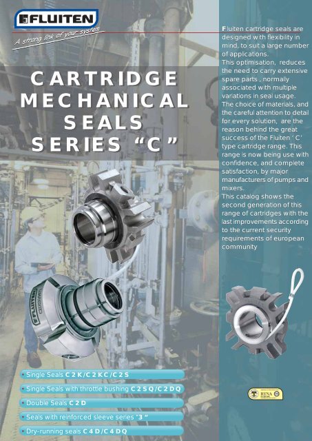
CARTRIDGE<br />
MECHANICAL<br />
SEALS<br />
SERIES “C”<br />
• Single Seals C2K/C2KC/C2S<br />
• Single Seals with throttle bushing C2SQ/C2DQ<br />
• Double Seals C2D<br />
• Seals with reinforced sleeve <strong>series</strong> “3”<br />
• Dry-running <strong>seals</strong> C4D/C4DQ<br />
Fluiten <strong>cartridge</strong> <strong>seals</strong> are<br />
designed with flexibility in<br />
mind, to suit a large number<br />
of applications.<br />
This optimisation, reduces<br />
the need to carry extensive<br />
spare parts , normally<br />
associated with multiple<br />
variations in seal usage.<br />
The choice of materials, and<br />
the careful attention to detail<br />
for every solution, are the<br />
reason behind the great<br />
success of the Fluiten ‘ C’<br />
type <strong>cartridge</strong> range. This<br />
range is now being use with<br />
confidence, and complete<br />
satisfaction, by major<br />
manufacturers of pumps and<br />
mixers.<br />
This catalog shows the<br />
second generation of this<br />
range of <strong>cartridge</strong>s with the<br />
last improvements according<br />
to the current security<br />
requirements of european<br />
community
2<br />
SINGLE SEALS<br />
CHARACTERISTICS<br />
CONNECTION FOR FLUSHING<br />
FROM PUMP DISCHARGE (PLAN 11)<br />
OR FLUSHING FROM EXTERNAL<br />
SOURCE (PLAN 32)<br />
(VERSIONS C2KC - C3KC)<br />
PATENTED DRIVE<br />
SPRING<br />
“DINAMIC” GASKETS IN FLUIGAM<br />
(PTFE ENERGIZED) FOR<br />
TOTAL COMPABILITY<br />
(O-RING ALTERNATIVE)<br />
MATERIALS:<br />
MATERIALS:<br />
STATIONARY SEAT:<br />
Graphite<br />
Silicon carbide<br />
Tungsten carbide<br />
ROTARY FACE:<br />
Silicon carbide<br />
Tungsten carbide<br />
“STATIC” GASKETS IN PTFE<br />
FOR TOTAL COMPABILITY<br />
(O-RING ALTERNATIVE)<br />
STATIONARY SEAT:<br />
Silicon carbide<br />
ROTARY FACE:<br />
AISI 316+graphite<br />
AISI 316+silicon carbide<br />
SLOTTED SEAL GLAND PLATE<br />
FOR STUFFING BOXES OF<br />
DIFFERENT SIZES<br />
AUTO-POSITIONING<br />
DEVICE - REMOVING<br />
BEFORE START-UP<br />
BALANCED SEAL<br />
WITH SOLID RINGS<br />
C2K/C2KC/C3K/C3KC<br />
GASKETS:<br />
EPDM / FKM / PTFE (Fluigam)<br />
Perfluoroelastomers (if request)<br />
SPRING:<br />
Superinox<br />
C2S/C3S (C2SQ/C3SQ with throttle bushing for quench)<br />
GASKETS:<br />
EPDM / FKM<br />
Perfluoroelastomers<br />
THROTTLE BUSHING<br />
(C2SQ-C3SQ):<br />
Bronze<br />
SLOTTED SEAL GLAND PLATE<br />
FOR STUFFING BOXES OF<br />
DIFFERENT SIZES<br />
EXTERNAL<br />
MULTI-SPRING<br />
AUTO-POSITIONING<br />
DEVICE - REMOVING<br />
BEFORE START-UP<br />
REINFORCED SLEEVE<br />
(SERIES 3)<br />
OTHER METAL PARTS:<br />
AISI 316<br />
CONNECTION FOR FLUSHING<br />
FROM PUMP DISCHARGE (PLAN 11)<br />
OR FLUSHING FROM EXTERNAL<br />
SOURCE (PLAN 32)<br />
(VERSIONS C2KC - C3KC)<br />
REINFORCED SLEEVE<br />
WITH LARGE CLEARANCE<br />
(SERIES 3)<br />
SPRINGS:<br />
AISI 316<br />
Hastelloy (if request)<br />
OTHER METAL PARTS:<br />
AISI 316<br />
Hastelloy (if request)
DUAL SEAL CAN USE EITHER<br />
A PRESSURIZED BARRIER FLUID<br />
(PLAN 53) OR AN UNPRESSURIZED<br />
BUFFER FLUID (PLAN 52)<br />
EXTERNAL<br />
MULTI-SPRINGS<br />
MATERIALS:<br />
DOUBLE SEALS<br />
CHARACTERISTICS<br />
CLEANED EXTERNAL PROFILE<br />
SUITABLE FOR SLURRIES AND<br />
HIGH VISCOSITY LIQUIDS<br />
REINFORCED SLEEVE<br />
WITH LARGE CLEARANCE<br />
UNDER SEAL RINGS (SERIES 3)<br />
STATIONARY SEAT:<br />
Graphite<br />
Silicon carbide<br />
Tungsten carbide<br />
ROTARY FACE:<br />
Silicon carbide<br />
Tungsten carbide<br />
GASKETS:<br />
EPDM / FKM<br />
Perfluoroelastomers<br />
PRODUCT SIDE<br />
C2D/C3D/C4D<br />
(C2DQ/C3DQ/C4DQ with throttle bushing for quench)<br />
BALANCED SEAL<br />
WITH SOLID FACE<br />
SPRINGS:<br />
AISI 316<br />
Hastelloy (if request)<br />
OTHER METAL PARTS:<br />
AISI 316<br />
Hastelloy (if request)<br />
CONNECTIONS FOR BARRIER<br />
FLUID (PLAN 53) OR BUFFER<br />
FLUID (PLAN 52)<br />
PATENTED DRIVE DEVICE<br />
STATIONARY SEAT:<br />
Silicon carbide<br />
ROTARY FACE:<br />
AISI 316+graphite<br />
BI-DIRECTIONAL PUMPING<br />
DEVIDE FOR EFFECTIVE<br />
FLUID CINCULATION<br />
ATMOSPHERE SIDE<br />
GASKETS:<br />
EPDM / FKM<br />
Perfluoroelastomers (if request)<br />
SLOTTED SEAL GLAND PLATE<br />
FOR STUFFING BOXES OF<br />
DIFFERENT SIZES<br />
AUTO-POSITIONING<br />
DEVICE - REMOVING<br />
BEFORE START-UP<br />
CARBON v SILICON<br />
CARBIDE AUXILIARY SEAL<br />
COOLED BARRIED FLUID<br />
THROTTLE BUSHING<br />
(C2DQ/C3DQ/C4DQ):<br />
Bronze<br />
SPRING:<br />
Superinox<br />
3
4<br />
J<br />
CHEMICAL<br />
INDUSTRY<br />
MAIN<br />
CHARACTERISTICS<br />
BI-DIRECTIONAL<br />
Can be installed on<br />
clockwise or anticlockwise<br />
rotating shafts.<br />
UNIVERSAL<br />
Geometry and materials<br />
maximize its application<br />
range.<br />
SELF-POSITIONING<br />
Auto-positioning device<br />
removing before start-up<br />
PHARMACEUTICAL<br />
FIELD<br />
INDUSTRY<br />
FOOD<br />
INDUSTRY<br />
PAPER<br />
FIELD<br />
APPLICATIONS<br />
WATER<br />
TREATMENT<br />
ATEX COMPLIANCE<br />
CENTRIFUGAL<br />
PUMPS<br />
MACHINES<br />
<br />
SIDE ENTRY BOTTOM ENTRY<br />
MIXERS MIXERS<br />
<br />
TOP ENTRY<br />
MIXERS<br />
<br />
VERTICAL<br />
PUMPS<br />
The Cartridges FLUITEN <strong>seals</strong> range are certified according the ATEX directive 94/9/CE<br />
(TÜV) which has defined the European requirements for equipment installed in critical<br />
potential explosive areas.<br />
A declaration of conformity and a specific instruction manual can be supplied on demand.<br />
This documentation complete the equipment certification required for the duty validation.<br />
For high risk applications Fluiten can provide double <strong>mechanical</strong> <strong>seals</strong> lubricated and<br />
monitored by a thermocouple which has the probe located inside the stationary rings or<br />
in contact with the barrier fluid to have direct temperature relief.<br />
GALVANIC BARRIER<br />
RANGE : 0-200 °C<br />
OUTLET: 4-20 mA<br />
LOW HEAT<br />
GENERATION<br />
PRICE<br />
Engineered to reduce<br />
production costs without<br />
compromising its quality<br />
level.<br />
NO CATASTROPHIC<br />
FAILURES<br />
The absence of a bellows<br />
guarantees that, in case<br />
of failure, there is no total<br />
fluid leakage<br />
LOW TURBULENCE<br />
HEAT GENERATIONS<br />
Its internal geometry<br />
reduces the amount of heat<br />
generated by turbulences.<br />
ROBUST CARTRIDGE<br />
The seal includes 2 robust<br />
Seal complete of flange and<br />
clutch pins resistant to<br />
shaft sleeve to guarantee<br />
vibrations, cavitations and<br />
reliable and easy installation.<br />
<strong>mechanical</strong> stress.<br />
LARGE<br />
CLEARANCE<br />
RESISTANT TO<br />
ACIDS & BASES<br />
The seal is resistant to<br />
products that are moderately<br />
chemically aggressive.<br />
SELF-CLEANING<br />
The seal eliminates by<br />
centrifugal force possible<br />
particle sedimentations.<br />
STOCK REDUCTION<br />
Ottimized material for<br />
stock reduction<br />
LOW EMISSIONS<br />
The geometry of the rings has<br />
been studied to avoid<br />
deformations and guarantee<br />
contact effectiveness<br />
THERMOCOUPLE (OPTIONAL)<br />
OXIDE MINERAL ISOLATED<br />
AISI 316 STEM<br />
ROTATING CONNECTION: 1/4" G<br />
RANGE : 0-200 °C
d4<br />
d3<br />
c<br />
b<br />
OPERATING LIMITS: (*)<br />
SEALS DIMENSIONS<br />
C2K - C2KC<br />
DIAMETER SPEED PRESSURE TEMPERATURE<br />
(mm) (m/sec) (bar)<br />
(°C)<br />
100<br />
25<br />
d1<br />
FLUI TEN<br />
C2K e C2KC with shaft<br />
diameter 50 mm<br />
CHARACTERISTICS:<br />
C2K<br />
Single <strong>cartridge</strong> seal, recommended for low duty service.<br />
PLAN 01 or PLAN 02 (see pag. 11)<br />
C2KC<br />
Single <strong>cartridge</strong> seal with connection for flushing,<br />
recommended for low duty service.<br />
PLAN 11 or PLAN 32 (see pag. 11)<br />
12<br />
0<br />
12<br />
+200<br />
–50<br />
(*) Pressure limitations depend upon a pressure-velocity relationship based<br />
on size, speed, face materials and fluid. Contact our Technical-Commercial<br />
office for technical specifics.<br />
0<br />
m<br />
l<br />
C2K<br />
b<br />
f<br />
11 8 13 9 2 35 1 10 16 7 15 12<br />
c<br />
h<br />
Seal<br />
Diam.<br />
25<br />
28<br />
30<br />
33<br />
35<br />
38<br />
40<br />
43<br />
45<br />
48<br />
50<br />
55<br />
60<br />
65<br />
70<br />
75<br />
80<br />
85<br />
90<br />
95<br />
g<br />
C2K e C2KC with shaft<br />
diameter > 50 mm<br />
m<br />
d4<br />
d1 d3 d4 b c f g g ‘ h h ‘ l l ‘ m r<br />
90<br />
d3<br />
119<br />
d1<br />
min<br />
max<br />
25 42 44 53 63 98 51.5 27 38.5 20 31.5 24,5 13 12 Rp 1/4"<br />
28 45 47 53 63 98 51,5 27 38,5 20 31,5 24,5 13 12 Rp 1/4"<br />
30 47 49 55 65 98 51,5 27 38,5 20 31,5 24,5 13 12 Rp 1/4"<br />
33 54 56 60 68 106 55 28 39.5 20 31,5 27 15.5 12 Rp 1/4"<br />
35 54 56 60 68 106 55 28 39,5 20 31,5 27 15,5 12 Rp 1/4"<br />
38 57 59 68 76 120 56 29 39,5 21 31,5 27 16.5 14 Rp 1/4"<br />
40 59 61 68 76 120 56 29 39,5 21 31,5 27 16,5 14 Rp 1/4"<br />
43 62 64 73 81 135 56 29 39,5 21 31,5 27 16,5 14 Rp 1/4"<br />
45 64 66 73 81 135 56 29 39,5 21 31,5 27 16,5 14 Rp 1/4"<br />
48 67 69 79 87 148 56 29 39,5 21 31,5 27 16,5 14 Rp 1/4"<br />
50 69 71 79 87 148 59 29.5 39,5 21.5 31,5 29.5 19.5 14 Rp 1/4"<br />
55 78 80 84 95 148 60.5 30.5 40 22 31,5 30 20.5 18 Rp 3/8"<br />
60 83 85 92 102 158 60,5 30,5 40 22 31,5 30 20,5 18 Rp 3/8"<br />
65 88 90 102 112 163 60,5 30,5 40 22 31,5 30 20,5 18 Rp 3/8"<br />
70 99 101 112 125 178 64.5 31.5 40 23 31,5 33 24.5 18 Rp 3/8"<br />
75 104 106 117 130 185 64,5 31,5 40 23 31,5 33 24,5 18 Rp 3/8"<br />
80 109 111 122 135 193 70 36 45.5 25.5 35 34 24,5 18 Rp 3/8"<br />
85 114 116 126 140 198 70 36 45,5 25,5 35 34 24,5 22 Rp 3/8"<br />
121<br />
134<br />
145<br />
95 124 126 139 150<br />
205<br />
208<br />
70<br />
70<br />
100 100 129 131 144 155 218 70<br />
Dimensions subject to modifications without notice.<br />
SEAL ELEMENTS:<br />
1 STATIONARY SEAT<br />
2 ROTARY FACE<br />
7 DRIVE COLLAR<br />
8 SHAFT SLEEVE<br />
9 ROTARY FACE GASKET<br />
10 STATIONARY SEAT GASKET<br />
l ‘<br />
C2KC<br />
11 8 13 35 9 2 1 10 16 7 15 12<br />
36<br />
36<br />
36<br />
45,5<br />
45,5<br />
45,5<br />
f<br />
h ‘<br />
25,5<br />
25,5<br />
25,5<br />
g ‘<br />
r<br />
35<br />
35<br />
35<br />
11 SHAFT SLEEVE GASKET<br />
12 SET SCREWS<br />
13 SPRING<br />
15 POSITIONING DEVICE<br />
16 FLANGE<br />
35 FLANGE GASKET<br />
34<br />
34<br />
34<br />
24,5 22<br />
24,5 22<br />
24,5 22<br />
Rp 3/8"<br />
Rp 3/8"<br />
Rp 3/8"<br />
5
6<br />
d4<br />
d3<br />
OPERATING LIMITS: (*)<br />
DIAMETER<br />
(mm)<br />
100<br />
25<br />
d1<br />
c<br />
b<br />
CHARACTERISTICS:<br />
C2S<br />
Single <strong>cartridge</strong> seal, recommended for general purpose.<br />
PLAN 11 or PLAN 32 (see pag. 11)<br />
C2SQ<br />
Single <strong>cartridge</strong> seal with throttle bushing for low pressure<br />
quench (< 1 bar), recommended for general purpose.<br />
PLAN 11/62 or PLAN 32/62 (see pag. 11)<br />
DIAMETER TEMPERATURE<br />
SPEED<br />
(m/sec)<br />
12<br />
0<br />
C2S<br />
SEALS DIMENSIONS<br />
C2S - C2SQ<br />
PRESSURE<br />
(bar)<br />
25<br />
0<br />
TEMPERATURE<br />
(°C)<br />
+250<br />
–50<br />
(*) Pressure limitations depend upon a pressure-velocity relationship based<br />
on size, speed, face materials and fluid. Contact our Technical-Commercial<br />
office for technical specifics.<br />
l<br />
f<br />
11 8 13 35 9 2 1 10 16 7 15 12<br />
FLUI TEN<br />
C2S with shaft<br />
diameter 50 mm<br />
m<br />
b<br />
r<br />
h<br />
g<br />
c<br />
m<br />
C2S with shaft<br />
diameter > 50 mm<br />
C2SQ with shaft<br />
diameter from 25 to 100 mm<br />
d4<br />
d3<br />
d1<br />
Seal d1 d3 d4 b c f f' g g' h h' l m r<br />
Diam.<br />
min max<br />
25 25 43 44 51 63 98 63,5 74,5 38,5 49,5 31,5 33,5 25 12 Rp 1/4”<br />
28 28 46 47 52 63 98 63,5 74,5 38,5 49,5 31,5 33,5 25 12 Rp 1/4”<br />
30 30 48 49 56 65 98 63,5 74,5 38,5 49,5 31,5 33,5 25 12 Rp 1/4”<br />
32 32 50 51 57 68 106 63,5 74,5 38,5 49,5 31,5 33,5 25 12 Rp 1/4”<br />
33 33 53 54 61,5 68 106 64,5 78 39,5 53 31,5 36 25 12 Rp 1/4”<br />
35 35 53 54 61,5 68 106 64,5 78 39,5 53 31,5 36 25 12 Rp 1/4”<br />
38 38 56 57 66 76 120 64,5 79 39,5 54 31,5 37 25 14 Rp 1/4”<br />
40 40 58 59 68 76 120 64,5 79 39,5 54 31,5 37 25 14 Rp 1/4”<br />
43 43 61 62 70,5 81 135 64,5 79 39,5 54 31,5 37 25 14 Rp 1/4”<br />
45 45 63 64 73 81 135 64,5 79 39,5 54 31,5 37 25 14 Rp 1/4”<br />
48 48 66 67 75 87 148 64,5 79 39,5 54 31,5 37 25 14 Rp 1/4”<br />
50 50 68 69 78 87 148 64,5 81 39,5 56 31,5 39 25 14 Rp 1/4”<br />
55 55 73 74 83 95 148 65 82,5 40 57,5 31,5 40 25 18 Rp 3/8”<br />
60 60 78 79 91 102 158 65 82,5 40 57,5 31,5 40 25 18 Rp 3/8”<br />
65 65 83 84,5 98,5 112 163 65 82,5 40 57,5 31,5 40 25 18 Rp 3/8”<br />
70 70 93 95 108 125 178 65 87,5 40 62,5 31,5 45 25 18 Rp 3/8”<br />
75 75 98 100 113 130 185 65 87,5 40 62,5 31,5 45 25 18 Rp 3/8”<br />
80 80 105 107 118 135 193 77 99 47 69 36,5 49 30 18 Rp 3/8”<br />
85 85 110 113 123 140 198 77 99 47 69 36,5 49 30 22 Rp 3/8”<br />
90 90 115 118 130 145 205 77 99 47 69 36,5 49 30 22 Rp 3/8”<br />
95 95 121 124 135 150 208 78 100 47 69 36,5 49 31 22 Rp 3/8”<br />
100 100 126 129 140 155 218 78 100 47 69 36,5 49 31 22 Rp 3/8”<br />
Dimensions subject to modifications without notice.<br />
SEAL ELEMENTS:<br />
1 STATIONARY SEAT<br />
2 ROTARY FACE<br />
7 DRIVE COLLAR<br />
8 SHAFT SLEEVE<br />
9 ROTARY FACE “O” RING<br />
10 STATIONARY SEAT “O” RING<br />
10a THROTTLE BUSHING “O” RING<br />
11 SHAFT SLEEVE “O” RING<br />
l<br />
C2SQ<br />
11 8 13 35 9 2 1 10 16 10a 42 40a 7<br />
f ’<br />
h ’<br />
12 SET SCREWS<br />
13 SPRINGS<br />
15 POSITIONING DEVICE<br />
16 FLANGE<br />
35 FLANGE GASKET<br />
40a SNAP RING<br />
42 THROTTLE BUSHING<br />
g ’<br />
r<br />
15 12
d4<br />
d3<br />
CHARACTERISTICS:<br />
SEALS DIMENSIONS<br />
C2D - C2DQ<br />
C2D<br />
Double <strong>cartridge</strong> seal, recommended for high duty service.<br />
PLAN 52 or PLAN 53 o PLAN 54 (see pag. 11)<br />
C2DQ<br />
Single <strong>cartridge</strong> seal with throttle bushing for low pressure<br />
quench (< 1 bar), recommended for high duty service.<br />
PLAN 62 (see pag. 11)<br />
OPERATING LIMITS: (*)<br />
DIAMETER<br />
(mm)<br />
DIAMETER TEMPERATURE<br />
100<br />
25<br />
d1<br />
b<br />
SPEED<br />
(m/sec)<br />
12<br />
0<br />
C2D<br />
PRESSURE<br />
(bar)<br />
25<br />
0<br />
Externar fluid pressure:<br />
- C2D (tandem): atmospheric pressure<br />
- C2D (dual): 1-2 bar over product pressure<br />
TEMPERATURE<br />
(°C)<br />
+250<br />
–50<br />
(*) Pressure limitations depend upon a pressure-velocity relationship based<br />
on size, speed, face materials and fluid. Contact our Technical-Commercial<br />
office for technical specifics.<br />
l<br />
11 8 13 9 2 1 10 4a 13a 9a 2a 1a 10a 7 15<br />
c<br />
28<br />
35<br />
26<br />
m<br />
f<br />
o<br />
h<br />
d4<br />
r<br />
g<br />
d3<br />
16<br />
d1<br />
12<br />
Seal d1 d3 d4 b c f g h l m o r<br />
Diam.<br />
min max<br />
C2DQ<br />
25 25 43 44 51 63 98 94 49,5 33,5 44,5 12 6 Rp 1/4”<br />
28 28 46 47 52 63 98 94 49,5 33,5 44,5 12 6 Rp 1/4”<br />
30 30 48 49 56 65 98 94 49,5 33,5 44,5 12 6 Rp 1/4”<br />
32 32 50 51 57 67 106 94 49,5 33,5 44,5 12 6 Rp 1/4”<br />
33 33 53 54 61,5 71 106 97,5 53 36 44,5 12 6 Rp 1/4”<br />
35 35 53 54 61,5 71 106 97,5 53 36 44,5 12 6 Rp 1/4”<br />
38 38 56 57 66 76 120 98,5 54 37 44,5 12 6 Rp 1/4”<br />
40 40 58 59 68 76 120 98,5 54 37 44,5 14 6 Rp 1/4”<br />
43 43 61 62 70,5 81 130 98,5 54 37 44,5 14 6 Rp 1/4”<br />
45 45 63 64 73 81 135 98,5 54 37 44,5 14 6 Rp 1/4”<br />
48 48 66 67 75 87 135 98,5 54 37 44,5 14 6 Rp 1/4”<br />
50 50 68 69 78 87 148 100,5 56 39 44,5 14 6 Rp 1/4”<br />
55 55 73 74 83 95 148 102 57,5 40 44,5 18 6 Rp 3/8”<br />
60 60 78 79 91 102 158 102 57,5 40 44,5 18 6 Rp 3/8”<br />
65 65 83 84,5 98,5 112 163 102 57,5 40 44,5 18 6 Rp 3/8”<br />
70 70 93 95 108 125 178 107 62,5 45 44,5 18 6 Rp 3/8”<br />
75 75 98 100 113 130 185 107 62,5 45 44,5 18 6 Rp 3/8”<br />
80 80 105 107 118 135 193 121 69 49 52 18 6 Rp 3/8”<br />
85 85 110 113 123 140 198 121 69 49 52 22 6 Rp 3/8”<br />
90 90 115 118 130 145 205 121 69 49 52 22 6 Rp 3/8”<br />
95 95 121 124 135 150 208 123 69 49 54 22 6 Rp 3/8”<br />
100 100 126 129 140 155 218 123 69 49 54 22 6 Rp 3/8”<br />
Dimensions subject to modifications without notice.<br />
SEAL ELEMENTS:<br />
1 STATIONARY SEAT 10a THROTTLE BUSHING “O” RING (C2DQ)<br />
1a STATIONARY SEAT<br />
11 SHAFT SLEEVE “O” RING<br />
2 ROTARY FACE<br />
12 SET SCREWS<br />
2a ROTARY FACE<br />
13 SPRINGS<br />
4a SEAL BODY 13a SPRING<br />
7 DRIVE COLLAR<br />
15 POSITIONING DEVICE<br />
8 SHAFT SLEEVE<br />
16 FLANGE<br />
9 ROTARY FACE “O” RING<br />
26 EXTERNAL FLANGE GASKET<br />
9a ROTARY FACE “O” RING<br />
35 FLANGE GASKET<br />
10 STATIONARY SEAT “O” RING 40a SNAP RING<br />
10a STATIONARY SEAT “O” RING (C2D)<br />
l<br />
28<br />
35<br />
26<br />
f<br />
o<br />
11 8 13 9 2 1 10 16 40a 42 10a 7 15 12<br />
h<br />
42 THROTTLE BUSHING<br />
r<br />
g<br />
7
8<br />
d4<br />
d3<br />
d1<br />
c<br />
b<br />
CHARACTERISTICS:<br />
FLUI TEN<br />
C3K e C3KC with shaft<br />
diameter 45 mm<br />
SEALS DIMENSIONS<br />
C3K - C3KC<br />
l<br />
C3K<br />
11 8 13 9 2 35 1 10 16<br />
7 15 12<br />
m<br />
f<br />
b<br />
h<br />
g<br />
c<br />
C3K e C3KC with shaft<br />
diameter > 45 mm<br />
m<br />
1 STATIONARY SEAT<br />
2 ROTARY FACE<br />
C3K<br />
Single <strong>cartridge</strong> seal, recommended for low duty service.<br />
Seal d1<br />
Diam.<br />
20 20<br />
d3<br />
42<br />
d4<br />
min max<br />
44 53<br />
b<br />
63<br />
c<br />
98<br />
f<br />
51.5<br />
g<br />
27<br />
g ‘<br />
38.5<br />
h<br />
20<br />
h ‘<br />
31.5<br />
l<br />
24,5<br />
l ‘<br />
13<br />
m<br />
12<br />
r<br />
Rp 1/4"<br />
PLAN 01 or PLAN 02 (see pag. 11)<br />
22 22 45 47 53 63 98 51,5 27 38,5 20 31,5 24,5 13 12 Rp 1/4"<br />
C3KC<br />
25 25 47 49 55 65 98 51,5 27 38,5 20 31,5 24,5 13 12 Rp 1/4"<br />
Single <strong>cartridge</strong> seal with connection for flushing,<br />
30 30 54 56 60 68 106 55 28 39.5 20 31,5 27 15.5 12 Rp 1/4"<br />
recommended for low duty service.<br />
PLAN 11 or PLAN 32 (see pag. 11)<br />
33<br />
35<br />
33<br />
35<br />
57<br />
59<br />
59<br />
61<br />
68<br />
68<br />
76<br />
76<br />
120<br />
120<br />
56<br />
56<br />
29<br />
29<br />
39,5<br />
39,5<br />
21<br />
21<br />
31,5<br />
31,5<br />
27<br />
27<br />
16,5<br />
16.5<br />
14<br />
14<br />
Rp 1/4"<br />
Rp 1/4"<br />
- Reinforced sleeve.<br />
- Important “Run-out” allowed for mixers applications.<br />
38 38 62 64 73 81 135 56 29 39,5 21 31,5 27 16,5 14 Rp 1/4"<br />
40 40 64 66 73 81 135 56 29 39,5 21 31,5 27 16,5 14 Rp 1/4"<br />
OPERATING LIMITS: (*)<br />
43<br />
45<br />
43<br />
45<br />
67<br />
69<br />
69<br />
71<br />
79<br />
79<br />
87<br />
87<br />
148<br />
148<br />
56<br />
59<br />
29<br />
29,5<br />
39,5<br />
39,5<br />
21<br />
21,5<br />
31,5<br />
31,5<br />
27<br />
29,5<br />
16,5<br />
19,5<br />
14<br />
14<br />
Rp 1/4"<br />
Rp 1/4"<br />
DIAMETER SPEED PRESSURE TEMPERATURE 48 48 78 80 84 95 148 60,5 30,5 40 22 31,5 30 20,5 18 Rp 3/8"<br />
(mm) (m/sec) (bar)<br />
(°C)<br />
50 50 78 80 84 95 148 60.5 30.5 40 22 31,5 30 20.5 18 Rp 3/8"<br />
90 12 12 +200<br />
53<br />
55<br />
53<br />
55<br />
83<br />
83<br />
85<br />
85<br />
92<br />
92<br />
102<br />
102<br />
158<br />
158<br />
60,5<br />
60,5<br />
30,5<br />
30,5<br />
40<br />
40<br />
22<br />
22<br />
31,5<br />
31,5<br />
30<br />
30<br />
20,5<br />
20,5<br />
18<br />
18<br />
Rp 3/8"<br />
Rp 3/8"<br />
58 58 88 90 102 112 163 60,5 30,5 40 22 31,5 30 20,5 18 Rp 3/8"<br />
20 0 0 –50<br />
60<br />
63<br />
60<br />
63<br />
88<br />
99<br />
90 102<br />
101 112<br />
112<br />
125<br />
163<br />
178<br />
60,5<br />
64,5<br />
30,5<br />
31.5<br />
40<br />
40<br />
22<br />
23<br />
31,5<br />
31,5<br />
30<br />
33<br />
20,5<br />
24.5<br />
18<br />
18<br />
Rp 3/8"<br />
Rp 3/8"<br />
65 65 99 101 112 125 178 64,5 31.5 40 23 31,5 33 24.5 18 Rp 3/8"<br />
(*) Pressure limitations depend upon a pressure-velocity relationship based<br />
68 68 104 106 117 130 185 64,5 31,5 40 23 31,5 33 24,5 18 Rp 3/8"<br />
on size, speed, face materials and fluid. Contact our Technical-Commercial<br />
office for technical specifics.<br />
70<br />
75<br />
70<br />
75<br />
109<br />
114<br />
111 122<br />
116 126<br />
135<br />
140<br />
193<br />
198<br />
70<br />
70<br />
36<br />
36<br />
45.5 25.5<br />
45,5 25,5<br />
35<br />
35<br />
34<br />
34<br />
24,5<br />
24,5<br />
18<br />
22<br />
Rp 3/8"<br />
Rp 3/8"<br />
80 80 119 121 134 145 205 70 36 45,5 25,5 35 34 24,5 22 Rp 3/8"<br />
85 85 124 126 139 150 208 70 36 45,5 25,5 35 34 24,5 22 Rp 3/8"<br />
90 90 129 131 144 155 218 70 36 45,5 25,5 35 34 24,5 22 Rp 3/8"<br />
d4<br />
d3<br />
Dimensions subject to modifications without notice.<br />
SEAL ELEMENTS:<br />
d1<br />
7 DRIVE COLLAR<br />
8 SHAFT SLEEVE<br />
9 ROTARY FACE GASKET<br />
10 STATIONARY SEAT GASKET<br />
l ‘<br />
C3KC<br />
f<br />
h ‘<br />
11 SHAFT SLEEVE GASKET<br />
12 SET SCREWS<br />
13 SPRING<br />
15 POSITIONING DEVICE<br />
16 FLANGE<br />
35 FLANGE GASKET<br />
11 8 13 35 9 2 1 10 16 7 15 12<br />
g ‘<br />
r
d4<br />
d3<br />
c<br />
b<br />
CHARACTERISTICS:<br />
C3S<br />
Single <strong>cartridge</strong> seal, for general purpose.<br />
PLAN 11 or PLAN 32 (see pag. 11)<br />
OPERATING LIMITS: (*)<br />
90<br />
20<br />
d1<br />
FLUI TEN<br />
C3S with shaft<br />
diameter 45 mm<br />
SEALS DIMENSIONS<br />
C3S - C3SQ<br />
C3SQ<br />
Single <strong>cartridge</strong> seal with throttle bushing for low pressure<br />
quench (< 1 bar), recommended for general purpose.<br />
PLAN 11/62 or PLAN 32/62 (see pag. 11)<br />
- Reinforced sleeve.<br />
- Important “Run-out” allowed for mixers applications.<br />
DIAMETER SPEED PRESSURE<br />
TEMPERATURE<br />
(mm) (m/sec) (bar)<br />
(°C)<br />
12<br />
0<br />
C3S<br />
25<br />
0<br />
+250<br />
–50<br />
(*) Pressure limitations depend upon a pressure-velocity relationship based<br />
on size, speed, face materials and fluid. Contact our Technical-Commercial<br />
office for technical specifics.<br />
l<br />
m<br />
b<br />
f<br />
11 8 13 35 9 2 1 10 16 7 15 12<br />
c<br />
h<br />
g<br />
C3S with shaft<br />
diameter > 45 mm<br />
C3SQ with shaft<br />
diameter from 20 to 90 mm<br />
r<br />
m<br />
d4<br />
d3<br />
d1<br />
SEAL ELEMENTS:<br />
1 STATIONARY SEAT<br />
2 ROTARY FACE<br />
7 DRIVE COLLAR<br />
8 SHAFT SLEEVE<br />
9 ROTARY FACE “O” RING<br />
10 STATIONARY SEAT “O” RING<br />
10a THROTTLE BUSHING “O” RING<br />
11 SHAFT SLEEVE “O” RING<br />
l<br />
C3SQ<br />
11 8 13 9 35 2 1 10 16 10a 42 40a 7<br />
f ‘<br />
h ‘<br />
g ‘<br />
r<br />
12 SET SCREWS<br />
13 SPRINGS<br />
15 POSITIONING DEVICE<br />
16 FLANGE<br />
35 FLANGE GASKET<br />
40a SNAP RING<br />
42 THROTTLE BUSHING<br />
15 12<br />
Shaft d1<br />
Diam.<br />
d3 d4<br />
min max<br />
b c f f' g g' h h' l m r<br />
20 20 43 44 51 63 98 63,5 74,5 38,5 49,5 31,5 33,5 25 12 Rp 1/4”<br />
22 22 46 47 52 63 98 63,5 74,5 38,5 49,5 31,5 33,5 25 12 Rp 1/4”<br />
25 25 48 49 56 65 98 63,5 74,5 38,5 49,5 31,5 33,5 25 12 Rp 1/4”<br />
28 28 50 51 57 68 106 63,5 74,5 38,5 49,5 31,5 33,5 25 12 Rp 1/4”<br />
30 30 53 54 61,5 68 106 64,5 78 39,5 53 31,5 36 25 12 Rp 1/4”<br />
32 32 56 57 66 76 120 64,5 79 39,5 54 31,5 37 25 12 Rp 1/4”<br />
33 33 56 57 66 76 120 64,5 79 39,5 54 31,5 37 25 14 Rp 1/4”<br />
35 35 58 59 68 76 120 64,5 79 39,5 54 31,5 37 25 14 Rp 1/4”<br />
38 38 61 62 70,5 81 135 64,5 79 39,5 54 31,5 37 25 14 Rp 1/4”<br />
40 40 63 64 73 81 135 64,5 79 39,5 54 31,5 37 25 14 Rp 1/4”<br />
43 43 66 67 75 87 148 64,5 79 39,5 54 31,5 37 25 14 Rp 1/4”<br />
45 45 68 69 78 87 148 64,5 81 39,5 56 31,5 39 25 14 Rp 1/4”<br />
48 48 73 74 83 95 148 65 82,5 40 57,5 31,5 40 25 18 Rp 3/8”<br />
50 50 73 74 83 95 148 65 82,5 40 57,5 31,5 40 25 18 Rp 3/8”<br />
53 53 78 79 91 102 158 65 82,5 40 57,5 31,5 40 25 18 Rp 3/8”<br />
55 55 78 79 91 102 158 65 82,5 40 57,5 31,5 40 25 18 Rp 3/8”<br />
58 58 83 84,5 98,5 112 163 65 82,5 40 57,5 31,5 40 25 18 Rp 3/8”<br />
60 60 83 84,5 98,5 112 163 65 82,5 40 57,5 31,5 40 25 18 Rp 3/8”<br />
63 63 93 95 108 125 178 65 87,5 40 62,5 31,5 45 25 18 Rp 3/8”<br />
65 65 93 95 108 125 178 65 87,5 40 62,5 31,5 45 25 18 Rp 3/8”<br />
68 68 98 100 113 130 185 65 87,5 40 62,5 31,5 45 25 18 Rp 3/8”<br />
70 70 105 107 118 135 193 77 99 47 69 36,5 49 30 18 Rp 3/8”<br />
75 75 110 113 123 140 198 77 99 47 69 36,5 49 30 22 Rp 3/8”<br />
80 80 115 118 130 145 205 77 99 47 69 36,5 49 30 22 Rp 3/8”<br />
85 85 121 124 135 150 208 78 100 47 69 36,5 49 31 22 Rp 3/8”<br />
90 90 126 129 140 155 218 78 100 47 69 36,5 49 31 22 Rp 3/8”<br />
Dimensions subject to modifications without notice.<br />
9
10<br />
d4<br />
d3<br />
d1<br />
SEALS DIMENSIONS<br />
C3D - C3DQ - C4D - C4DQ<br />
C3D<br />
C4D<br />
CHARACTERISTICS:<br />
l<br />
28<br />
35<br />
26<br />
f<br />
o<br />
11 8 13 9 2 1 10 4a 13a 9a 2a 1a 10a 7 15<br />
b<br />
c<br />
m<br />
h<br />
g<br />
r<br />
d4<br />
16<br />
d3<br />
12<br />
C3DQ<br />
C4DQ<br />
Seal<br />
Diam.<br />
C3D<br />
Double <strong>cartridge</strong> seal, recommended for high duty service. 20<br />
d1<br />
20<br />
d3<br />
43<br />
d4<br />
min max<br />
44 51<br />
b<br />
63<br />
c<br />
98<br />
f<br />
94<br />
g<br />
49,5<br />
h<br />
33,5<br />
l<br />
44,5<br />
m<br />
12<br />
o<br />
6<br />
r<br />
Rp 1/4”<br />
PLAN 52 or PLAN 53 o PLAN 54 (see pag. 11)<br />
22 22 46 47 52 63 98 94 49,5 33,5 44,5 12 6 Rp 1/4”<br />
C3DQ<br />
Single <strong>cartridge</strong> seal with throttle bushing for low pressure<br />
quench (< 1 bar), recommended for high duty service.<br />
25<br />
28<br />
25<br />
28<br />
48<br />
50<br />
49<br />
51<br />
56<br />
57<br />
65<br />
67<br />
98<br />
106<br />
94<br />
94<br />
49,5<br />
49,5<br />
33,5<br />
33,5<br />
44,5<br />
44,5<br />
12<br />
12<br />
6<br />
6<br />
Rp 1/4”<br />
Rp 1/4”<br />
PLAN 62 (see pag. 11)<br />
30 30 53 54 61,5 71 106 97,5 53 36 44,5 12 6 Rp 1/4”<br />
C4D<br />
32 32 56 57 66 76 120 98,5 54 37 44,5 12 6 Rp 1/4”<br />
Duoble <strong>cartridge</strong> dry-running seal.<br />
Nitrogen PLAN 54 or PLAN 02/61 with connections<br />
33 33 56 57 66 76 120 98,5 54 37 44,5 12 6 Rp 1/4”<br />
purchaser’s use. (see pag. 11)<br />
35 35 58 59 68 76 120 98,5 54 37 44,5 14 6 Rp 1/4”<br />
C4DQ<br />
38 38 61 62 70,5 81 130 98,5 54 37 44,5 14 6 Rp 1/4”<br />
Single <strong>cartridge</strong> dry-running seal.<br />
PLAN 02 or PLAN 02/62 with throttle bushing (see pag. 11)<br />
40 40 63 64 73 81 135 98,5 54 37 44,5 14 6 Rp 1/4”<br />
- Reinforced sleeve.<br />
- Important “Run-out” allowed for mixers applications.<br />
43<br />
45<br />
43<br />
45<br />
66<br />
68<br />
67<br />
69<br />
75<br />
78<br />
87<br />
87<br />
135<br />
148<br />
98,5<br />
100,5<br />
54<br />
56<br />
37<br />
39<br />
44,5<br />
44,5<br />
14<br />
14<br />
6<br />
6<br />
Rp 1/4”<br />
Rp 1/4”<br />
OPERATING LIMITS: (*)<br />
48 48 73 74 83 95 148 102 57,5 40 44,5 18 6 Rp 3/8”<br />
50 50 73 74 83 95 148 102 57,5 40 44,5 18 6 Rp 3/8”<br />
DIAMETER SPEED PRESSURE TEMPERATURE 53 53 78 79 91 102 158 102 57,5 40 44,5 18 6 Rp 3/8”<br />
(mm) (m/sec) (bar)<br />
(°C) 55 55 78 79 91 102 158 102 57,5 40 44,5 18 6 Rp 3/8”<br />
90 12<br />
(0,3 m/s for<br />
C4D/C4DQ)<br />
25<br />
(3 bar for<br />
C4D/C4DQ)<br />
+250<br />
(150 °C for<br />
C4D/C4DQ)<br />
58<br />
60<br />
58<br />
60<br />
83<br />
83<br />
84,5<br />
84,5<br />
98,5<br />
98,5<br />
112<br />
112<br />
163<br />
163<br />
102<br />
102<br />
57,5<br />
57,5<br />
40<br />
40<br />
44,5<br />
44,5<br />
18<br />
18<br />
6<br />
6<br />
Rp 3/8”<br />
Rp 3/8”<br />
63 63 93 95 108 125 178 107 62,5 45 44,5 18 6 Rp 3/8”<br />
20 0 0 –50<br />
65<br />
68<br />
65<br />
68<br />
93<br />
98<br />
95<br />
100<br />
108<br />
113<br />
125<br />
130<br />
178<br />
185<br />
107<br />
107<br />
62,5<br />
62,5<br />
45<br />
45<br />
44,5<br />
44,5<br />
18<br />
18<br />
6<br />
6<br />
Rp 3/8”<br />
Rp 3/8”<br />
70 70 105 107 118 135 193 121 69 49 52 18 6 Rp 3/8”<br />
75 75 110 113 123 140 198 121 69 49 52 22 6 Rp 3/8”<br />
Externar fluid pressure:<br />
- C3D (tandem): atmospheric pressure<br />
80 80 115 118 130 145 205 121 69 49 52 22 6 Rp 3/8”<br />
- C3D (dual): 1-2 bar over product pressure<br />
85 85 121 124 135 150 208 123 69 49 54 22 6 Rp 3/8”<br />
(*) Pressure limitations depend upon a pressure-velocity relationship based 90 90 126 129 140 155 218 123 69 49 54 22 6 Rp 3/8”<br />
on size, speed, face materials and fluid. Contact our Technical-Commercial<br />
office for technical specifics.<br />
Dimensions subject to modifications without notice.<br />
d1<br />
SEAL ELEMENTS:<br />
1 STATIONARY SEAT 10a THROTTLE BUSHING “O” RING (C3DQ)<br />
1a STATIONARY SEAT<br />
11 SHAFT SLEEVE “O” RING<br />
2 ROTARY FACE<br />
12 SET SCREWS<br />
2a ROTARY FACE<br />
13 SPRINGS<br />
4a SEAL BODY 13a SPRING<br />
7 DRIVE COLLAR<br />
15 POSITIONING DEVICE<br />
8 SHAFT SLEEVE<br />
16 FLANGE<br />
9 ROTARY FACE “O” RING<br />
26 EXTERNAL FLANGE GASKET<br />
9a ROTARY FACE “O” RING<br />
35 FLANGE GASKET<br />
10 STATIONARY SEAT “O” RING 40a SNAP RING<br />
10a STATIONARY SEAT “O” RING (C3D)<br />
l<br />
28<br />
35<br />
26<br />
f<br />
o<br />
42 THROTTLE BUSHING<br />
11 8 13 9 2 1 10 16 40a 42 10a 7 15 12<br />
h<br />
g<br />
r
API PLANS<br />
APPLICABLE<br />
FOR ORIZONTAL CENTRIFUGAL PUMPS:<br />
PLAN 02<br />
Dead-ended seal chamber<br />
with no circulation of flushed fluid.<br />
C2DQ - C3DQ<br />
With PLAN 62<br />
Optional<br />
Plugged connections<br />
for possible future<br />
circulating fluid.<br />
PLAN 52<br />
Vent<br />
Normally<br />
open<br />
Reservoir<br />
Un-pressurized external<br />
fluid reservoir with forced circulation;<br />
(typically used with tandem seal<br />
arrangement)<br />
C2D - C3D<br />
PLAN 01<br />
Internal recirculation from<br />
pump discharge to seal.<br />
C2K - C3K<br />
Optional<br />
PLAN 53<br />
Pressurized external fluid<br />
reservoir with forced circulation;<br />
(typically used with double seal<br />
arrangement)<br />
C2D - C3D<br />
External<br />
pressure inlet<br />
Reservoir<br />
FOR TOP ENTRY MIXERS:<br />
Plugged connections<br />
for possible future<br />
circulating fluid.<br />
PLAN 02<br />
Dead-ended seal chamber<br />
with no circulation of flushed fluid.<br />
C4D - C4DQ<br />
With PLAN 62<br />
PLAN 62<br />
External fluid quench (steam,<br />
gas, water, etc.) typically used<br />
whit throttle bushing or auxiliary<br />
sealing device.<br />
C3DQ - C4DQ<br />
PLAN 52<br />
Un-pressurized external<br />
fluid reservoir with forced circulation;<br />
(typically used with tandem seal<br />
arrangement)<br />
API PLAN LEGEND<br />
Pressure indicator<br />
Temperature indicator<br />
Pressure switch<br />
For not present specific applications contact our Technical-Commercial office<br />
C3D<br />
Vent<br />
Normally<br />
open<br />
Normally<br />
open<br />
Reservoir<br />
Circulation pump<br />
Low pressure alarm<br />
High level alarm<br />
Low level alarm<br />
High flow alarm<br />
PLAN 11<br />
Recirculation from pump<br />
case through orifice to seal.<br />
C2KC - C3KC<br />
C2S - C3S<br />
PLAN 54<br />
Circulation of clean fluid from<br />
external system; (typically<br />
used with double seal<br />
arrangement)<br />
C2D - C3D<br />
External<br />
pressure inlet<br />
PLAN 53<br />
Pressurized external fluid<br />
reservoir with forced circulation;<br />
(typically used with double seal<br />
arrangement)<br />
C3D<br />
Normally<br />
open<br />
Reservoir<br />
Circulation pump<br />
Flushing inlet/<br />
pressurization<br />
Flushing outlet/<br />
pressurization<br />
Barrier gas inlet<br />
Barrier gas outlet<br />
By vendor<br />
By<br />
purch.<br />
PLAN 32<br />
Injection to seal from external<br />
source of clean fluid.<br />
C2KC - C3KC<br />
C2S - C3S<br />
PLAN 62<br />
External fluid quench (steam,<br />
gas, water, etc.) typically used<br />
whit throttle bushing or auxiliary<br />
sealing device.<br />
C2SQ - C3SQ<br />
C2DQ - C3DQ<br />
Optional<br />
GBI GBO<br />
PLAN 74<br />
Pressurized gas barrier regulated<br />
from control panel; (typically used<br />
with dry-running double seal<br />
arrangement)<br />
C4D<br />
Strainer<br />
Flow-regulation valve<br />
Block valve<br />
Check valve<br />
Orifice<br />
11
CAT029 ENG – Rev. 05 / 10<br />
SERVICE<br />
SOLUTIONS<br />
The Fluiten service department, independent from the<br />
production process, offer a fast, flexible and high quality<br />
assistance for any necessity.<br />
During the repair process are also considered up grading<br />
evaluation to make the <strong>seals</strong> compliant to the recent<br />
environmental rules and using the present superior material<br />
technology.<br />
High experienced technicians operates according the quality<br />
manual which define the level of repair to the initial<br />
manufacturing tolerances and performances.<br />
Customer and After sales service for assistance and technical support tel. +39 02 339403.1<br />
or contact us by info@fluiten.it or www.fluiten.it<br />
Distributed by:<br />
A A strong link link of of your system<br />
FLUITEN ITALIA SpA<br />
20016 Pero (Milano) Italy • Via L. Da Vinci, 14 • Telefono +39 02. 339403.1 Fax +39 02. 3538641<br />
www.fluiten.it E-mail: info@fluiten.it