1988.Techniques.in.s..
1988.Techniques.in.s..
1988.Techniques.in.s..

You also want an ePaper? Increase the reach of your titles
YUMPU automatically turns print PDFs into web optimized ePapers that Google loves.
f<br />
http://jurassic.ru/<br />
Techniques <strong>in</strong> Sedimentology<br />
Edited by<br />
MAURICE TUCKER<br />
BSc, PhD<br />
Department of Geological Sciences<br />
University of Durham<br />
Durham DH1 3LE<br />
UK<br />
Blackwell Scientific Publications<br />
OXFORD LONDON EDINBURGH BOSTON MELBOURNE
© 1988 by<br />
Blackwell Scientific Publications<br />
Editorial offices:<br />
Osney Mead, Oxford OX2 OEL<br />
8 John Street, London WC1N 2ES<br />
23 A<strong>in</strong>slie Place, Ed<strong>in</strong>burgh EH3 6AJ<br />
3 Cambridge Center, Suite 208<br />
Cambridge, Massachusetts 02142, USA<br />
107 Barry Street, Carlton<br />
Victoria 3053, Australia<br />
All rights reserved. No part of this<br />
publication may be reproduced, stored<br />
<strong>in</strong> a retrieval system, or transmitted,<br />
<strong>in</strong> any form or by any means,<br />
electronic, mechanical, photocopy<strong>in</strong>g,<br />
record<strong>in</strong>g or otherwise without<br />
the prior permission of the<br />
copyright owner.<br />
First published 1988 •<br />
Repr<strong>in</strong>ted 1989<br />
Set by Setrite Typesetters Ltd, Hong Kong<br />
Pr<strong>in</strong>ted and bound <strong>in</strong> Great Brita<strong>in</strong> by<br />
William Clowes, Beccles, Suffolk<br />
DISTRIBUTORS<br />
Marston Book Services Ltd<br />
POBox87<br />
Oxford OX2 ODT<br />
(.Orders .Tel: 0865 791155<br />
Fax: 0865791927<br />
Telex: 837515)<br />
USA<br />
Publishers' Bus<strong>in</strong>ess Services<br />
PO Box 447<br />
Brookl<strong>in</strong>e Village<br />
Massachusetts 02147<br />
(Orders: Tel. (617) 542-7678)<br />
Canada<br />
Oxford University Press<br />
70 Wynford Drive<br />
Don Mills<br />
Ontario M3C 1J9<br />
(Orders: Tel: (416) 441-2941)<br />
Australia<br />
Blackwell Scientific Publications<br />
(Australia) Pty Ltd<br />
107 Barry Street<br />
Carlton, Victoria 3053<br />
(Orders: Tel. (03) 347 0300)<br />
British Library<br />
Catalogu<strong>in</strong>g <strong>in</strong> Publication Data<br />
Techniques <strong>in</strong> sedimentology.<br />
1. Sedimentology — Technique<br />
I. Tucker, Maurice E.<br />
551.3'04'028 QE471<br />
ISBN 0-632-01361-3<br />
ISBN 0-632-01372-9 Pbk<br />
Library of Congress<br />
Catalog<strong>in</strong>g-<strong>in</strong>-Publication Data<br />
Techniques <strong>in</strong> sedimentology.<br />
Bibliography: p.<br />
Includes <strong>in</strong>dex.<br />
1. Sedimentology I. Tucker, Maurice E.<br />
471 .T37 1988 552'.5 87-34120<br />
ISBN 0-632-01361-3<br />
ISBN 0-632-01372-9 (pbk.)<br />
http://jurassic.ru/<br />
Contents<br />
List of contributors vii<br />
Preface ix<br />
1 Introduction 1<br />
MAURICE TUCKER<br />
2 Collection and analysis of field data 5<br />
JOHN GRAHAM<br />
3 Gra<strong>in</strong> size determ<strong>in</strong>ation and <strong>in</strong>terpretation 63<br />
JOHN MCMANUS<br />
4 Microscopical techniques: I. Slices, slides, sta<strong>in</strong>s and peels 86<br />
JOHN MILLER<br />
5 Microscopical techniques: II. Pr<strong>in</strong>ciples of sedimentary petrography 108<br />
GILL HARWOOD<br />
6 Cathodolum<strong>in</strong>escence microscopy 174<br />
JOHN MILLER<br />
7 X-ray powder diffraction of sediments 191<br />
RON HARDY and MAURICE TUCKER<br />
8 Use of the scann<strong>in</strong>g electron microscope <strong>in</strong> sedimentology 229<br />
NIGEL TREWIN<br />
9 Chemical analysis of sedimentary rocks 274<br />
IAN FAIRCHILD, GRAHAM HENDRY, MARTIN QUEST and<br />
MAURICE TUCKER<br />
References 355 ^<br />
Index 387
http://jurassic.ru/<br />
List of contributors<br />
IAN FAIRCHILD<br />
Department of Geological Sciences, The University, Birm<strong>in</strong>gham B15 2TT.<br />
JOHN GRAHAM<br />
Department of Geology, Tr<strong>in</strong>ity College, Dubl<strong>in</strong>, Eire.<br />
RON HARDY<br />
Department of Geologial Sciences, The University, Durham DH1 3LE.<br />
GILL HARWOOD<br />
Department of Geology, The University, Newcastle upon Tyne NE1 7RU.<br />
GRAHAM HENDRY<br />
Department of Geological Sciences, The University, Birm<strong>in</strong>gham B15 2TT.<br />
JOHN MCMANUS<br />
Department of Geology, The University, Dundee DDI 4HN.<br />
JOHN MILLER<br />
Grant Institute of Geology, The University, Ed<strong>in</strong>burgh EH9 3JW.<br />
MARTIN QUEST<br />
Department of Geological Sciences, The University, Birm<strong>in</strong>gham B15 2TT.<br />
Present address: Core Laboratories, Isleworth, Middlesex TW7 5AB.<br />
MAURICE NIGEL TREWIN TUCKER<br />
Department<br />
Department<br />
of<br />
of<br />
Geological<br />
Geology and<br />
Sciences,<br />
M<strong>in</strong>eralogy,<br />
The University,<br />
The University,<br />
Durham<br />
Aberdeen<br />
DH1 3LE.<br />
AB9 IAS.
http://jurassic.ru/<br />
Preface<br />
Sedimentologists are keen to discover the processes, conditio<br />
position and diagenesis of their rocks. They currently use a whoi 3 e n v i r<br />
"^ °nments of de<br />
cated <strong>in</strong>struments and mach<strong>in</strong>es, <strong>in</strong> addition to rout<strong>in</strong>e fieM. ra<br />
nge of . • •"<br />
' ^WorW Quite soDhistia<br />
Although geologists have been mak<strong>in</strong>g field observations f0r "d microsco '<br />
two decades there have been many new approaches to the colie^ 1<br />
^ ^00 years <strong>in</strong>"the U<br />
last<br />
0 1 1 3 n d data. New sedimentary structures and relationships are stil) b e T ' Processi'n oilfield<br />
studied rocks. The microscopic exam<strong>in</strong>ation of sediments is a n e' n<br />
^ ^°Und <strong>in</strong> 'classic' well<br />
S S e n t i a l<br />
tion and <strong>in</strong>terpretation of sediments, but there are ways to rn a x^ tool <strong>in</strong> the'd' ^<br />
1 1 2 e t n<br />
slice of rock will yield. Chemical analyses are be<strong>in</strong>g <strong>in</strong>crea*;., ? e <strong>in</strong>fr,rm »• esc<br />
"?~<br />
d S l<br />
r j - . • t A i j ngl v ,, 1S<br />
treated <strong>in</strong><br />
n<br />
and how samples are best prepared and viewed, and then gj V e s °w the mach<strong>in</strong>e works<br />
X a m p l e s soft-rock geology. A f<strong>in</strong>al chapter reviews the pr<strong>in</strong>ciples behi H of SEM uses <strong>in</strong><br />
t n e<br />
mentary rocks and discusses the collection and preparati0n 0^ chernistr of sedi<br />
techniques of electron beam microanalysis, XRF, AAS, TQp<br />
Saill<br />
ples, followed b the 6<br />
MS. Sections are <strong>in</strong>cluded on analytical quality and the repo r t j' ^A.A a n d s t ay e isJ<br />
£<br />
concludes with examples of the application of chemcial anal,, • ^ °^ re<br />
&ults ,<br />
rm.- u , • u T A . i i a<br />
s a n<br />
'ysis to c» A d the chapter<br />
S e<br />
This book is a multi-authored volume and so naturally theTo dirnento,<br />
u • .u u . .u . . e<br />
l e n t<br />
are ri;« ary problems,<br />
ment and emphasis throughout the text.<br />
Ultt<br />
erent levels of treat<br />
Techniques <strong>in</strong> Sedimentology is written for f<strong>in</strong>al year under<br />
r a U a t e<br />
to give them <strong>in</strong>formation and ideas on how to deal with their r' ^ s and post<br />
t l l e n e<br />
<strong>in</strong> the laboratory dur<strong>in</strong>g dissertation and thesis research. Much ^ 'd and sa" T'<br />
U s e r<br />
is also provided which will be relevant to lecture courses Tu„ , ul backor^ • ,<br />
c • i A- | . . . ' A * . A<br />
h e<br />
. boot.,, K<br />
8 r<br />
°nnd material<br />
to professional sedimentologists, <strong>in</strong> <strong>in</strong>dustry and a<br />
cademja ^ also be <strong>in</strong>valuable<br />
scientists, as a source book for the various techniques covers a<br />
n v a u a e<br />
''ke, a n . '<br />
t o<br />
v c r<br />
. . , . , •• , ed and t other earth<br />
extract<strong>in</strong>g <strong>in</strong>formation from sedimentary rocks. " u<br />
tor tips a d<br />
n<br />
Maurice Tucker<br />
rhani, March 1988<br />
Uu<br />
IX
http://jurassic.ru/<br />
1 Introduction<br />
MAURICE TUCKER<br />
1.1 INTRODUCTION AND<br />
RATIONALE<br />
The study of sediments and sedimentary rocks has<br />
come a long way from the early days Of field observations<br />
followed by a cursory exam<strong>in</strong>ation of samples<br />
<strong>in</strong> the laboratory. Now many sophisticated techniques<br />
are applied to data collected <strong>in</strong> the field and to<br />
specimens back <strong>in</strong> the laboratory. Some of these<br />
techniques have been brought <strong>in</strong> from other branches<br />
of the earth sciences, while some have been specifically<br />
developed by sedimentologists.<br />
Research on sediments and sedimentary rocks is<br />
usually a progressive gather<strong>in</strong>g of <strong>in</strong>formation. First,<br />
there is the fieldwork, an essential part of any<br />
sedimentological project, from which data relat<strong>in</strong>g<br />
to the conditions and environments Of deposition<br />
are obta<strong>in</strong>ed. With modern sediments, measurements<br />
can be made of the various environmental<br />
parameters such as sal<strong>in</strong>ity, current velocity and<br />
suspended sediment content, and the sediments<br />
themselves can be subject to close scrut<strong>in</strong>y and<br />
sampl<strong>in</strong>g. With ancient sediments, the identification<br />
of facies types and facies associations follows from<br />
detailed exam<strong>in</strong>ation of sedimentary structures,<br />
lithologies, fossil content etc., and subsequent<br />
laboratory work on representative rocks. After consideration<br />
of depositional environment, the larger<br />
scale context of the sequence <strong>in</strong> its sedimentary<br />
bas<strong>in</strong> may be sought, necessitat<strong>in</strong>g <strong>in</strong>formation on<br />
the broad palaeogeographical sett<strong>in</strong>g, the tectonics<br />
of the region, both <strong>in</strong> terms of synsedimentary and<br />
post-sedimentary movements, and the subsurface<br />
structure, perhaps with <strong>in</strong>put from seismic sections.<br />
With an understand<strong>in</strong>g of a sedimentary rock's deposition<br />
and tectonic history, lead<strong>in</strong>g to an appreciation<br />
of the rock's burial history, the diagenetic<br />
changes can be studied to throw light on the patterns<br />
of cementation and alteration of the orig<strong>in</strong>al sediment,<br />
and on the nature of pore fluids which have<br />
moved through the sedimentary sequence. Although<br />
much <strong>in</strong>formation on the diagenesis can be obta<strong>in</strong>ed<br />
from petrograpic microscopic exam<strong>in</strong>ation of th<strong>in</strong><br />
sections of the rock, sophisticated <strong>in</strong>struments are<br />
<strong>in</strong>creas<strong>in</strong>gly used to analyse the rocks and their<br />
components for m<strong>in</strong>eralogical composition, major,<br />
m<strong>in</strong>or and trace elements, isotopic signatures and<br />
organic content. The data obta<strong>in</strong>ed provide much<br />
useful <strong>in</strong>formation on the diagenesis, and also on the<br />
orig<strong>in</strong>al depositional conditions.<br />
Which techniques to use <strong>in</strong> sedimentological research<br />
depend of course on the questions be<strong>in</strong>g<br />
asked. The aims of a project should be reasonably<br />
clear before work is commenced; know<strong>in</strong>g what<br />
answers are be<strong>in</strong>g sought makes it much easier to<br />
select the appropriate technique. There is usually<br />
not much po<strong>in</strong>t <strong>in</strong> hitt<strong>in</strong>g a rock with all the sophisticated<br />
techniques go<strong>in</strong>g, <strong>in</strong> the hope that someth<strong>in</strong>g<br />
mean<strong>in</strong>gful will come out of all the data. It may be<br />
that the problem would be solved with a few simple<br />
field measurements or five m<strong>in</strong>utes with the microscope<br />
on a th<strong>in</strong> section, rather than a detailed<br />
geochemical analysis giv<strong>in</strong>g hundreds of impressive<br />
numbers which add little to one's understand<strong>in</strong>g of<br />
the rock.<br />
The techniques available to sedimentologists, and<br />
those covered <strong>in</strong> this book, often cannot be used for<br />
all sedimentary rock types. It is necessary to be<br />
aware of what all the various <strong>in</strong>struments available<br />
<strong>in</strong> a well-found earth sciences department can do<br />
and how they can be used with sedimentary rocks.<br />
Many such <strong>in</strong>struments are more frequently used<br />
and operated by hard rocks petrologists and geo-'<br />
chemists, but they can be used with great success on<br />
sedimentary rocks, as long as one is still seek<strong>in</strong>g an<br />
answer to a particular question rather than just<br />
another analysis. Certa<strong>in</strong> techniques are best suited<br />
to specific sedimentary rock types and cannot be<br />
used generally to analyse any rock. In the next<br />
sections of this <strong>in</strong>troduction (1.2 to 1.9), the techniques<br />
covered <strong>in</strong> this book, <strong>in</strong> Chapters 2 to 9 are<br />
briefly reviewed. Not all the possible techniques<br />
available are <strong>in</strong>cluded <strong>in</strong> this book and Section 1.10<br />
notes what is omitted and where to f<strong>in</strong>d details. It<br />
also <strong>in</strong>dicates where new techniques <strong>in</strong> soft-rock<br />
geology are frequently published, so that the keen<br />
student can keep up to date with developments <strong>in</strong><br />
this field.
2 M.E.TUCKER<br />
1.2 COLLECTION AND ANALYSIS<br />
OF FIELD DATA: CHAPTER 2<br />
In Chapter 2, John Graham exam<strong>in</strong>es the rationale<br />
beh<strong>in</strong>d fieldwork, and the various ways <strong>in</strong> which<br />
field data can be collected and presented <strong>in</strong> graphic<br />
form are shown. The various sedimentary structures<br />
and the identification of lithologies and fossils are<br />
not described <strong>in</strong> detail s<strong>in</strong>ce there are textbooks on<br />
these topics (e.g. Coll<strong>in</strong>son & Thompson, 1982;<br />
Tucker, 1982), but the problems of recogniz<strong>in</strong>g certa<strong>in</strong><br />
structures are aired. The collection and analysis<br />
of palaeocurrent data (described <strong>in</strong> Section 2.3) are<br />
important <strong>in</strong> facies analysis and palaeogeographical<br />
reconstruction and statistical treatments are available<br />
to make the data more mean<strong>in</strong>gful. There are<br />
many ways <strong>in</strong> which to exam<strong>in</strong>e a sedimentary sequence<br />
for rhythms and cycles (Section 2.4) and<br />
aga<strong>in</strong> the field data can be manipulated by statistical<br />
analysis to reveal trends. This chapter also shows the<br />
many ways <strong>in</strong> which <strong>in</strong>formation from the field can<br />
be presented for publication.<br />
1.3 GRAIN SIZE DETERMINATION<br />
AND INTERPRETATION:<br />
CHAPTER 3<br />
It is very important to know quite precisely what the<br />
gra<strong>in</strong> size distribution is <strong>in</strong> a sediment sample and<br />
the procedures here are described by John McManus.<br />
Sample preparation varies from the unnecessary to<br />
hav<strong>in</strong>g to break up the rock <strong>in</strong>to its constituent<br />
gra<strong>in</strong>s, dissolve out the cement <strong>in</strong> acid, or make a<br />
th<strong>in</strong> section of the sample. Siev<strong>in</strong>g, sedimentation<br />
methods and Coulter counter analysis can be used<br />
for unconsolidated or disaggregated samples, but<br />
microscopic measurements are required for fully<br />
lithified sandstones and most limestones. With a<br />
gra<strong>in</strong> size analysis at hand, various statistical parameters<br />
are calculated. From these, with care, it is<br />
possible to make deductions on the sediment's conditions<br />
and environment of deposition.<br />
1.4 MICROSCOPIC TECHNIQUES I:<br />
SLICES, SLIDES, STAINS AND<br />
PEELS: CHAPTER 4<br />
The rock th<strong>in</strong> section is the basis of much rout<strong>in</strong>e<br />
description and <strong>in</strong>terpretation but all too often the<br />
production of the slide is not given thought. John<br />
Miller expla<strong>in</strong>s how the best can be achieved by<br />
double-polished th<strong>in</strong> sections and describes the various<br />
techniques of impregnat<strong>in</strong>g, sta<strong>in</strong><strong>in</strong>g and etch<strong>in</strong>g<br />
to encourage the slide to give up more of its hidden<br />
secrets. Acetate peels are frequently made of limestones<br />
and the manufacture of these is also discussed.<br />
1.5 MICROSCOPIC TECHNIQUES II:<br />
PRINCIPLES OF SEDIMENTARY<br />
PETROGRAPHY: CHAPTER 5<br />
This chapter is by Gill Harwood and follows on from<br />
the previous one by expla<strong>in</strong><strong>in</strong>g how the various<br />
m<strong>in</strong>erals and textures <strong>in</strong> sedimentary rocks can be<br />
recognized and <strong>in</strong>terpreted. The chapter is written <strong>in</strong><br />
such a way so that it is applicable to all sedimentary<br />
rock types, rather than discuss<strong>in</strong>g each separately,<br />
as is frequently the case <strong>in</strong> sedimentary petrography<br />
texts. There is a huge textbook literature on 'sed.<br />
pet.' and many of the books will be readily available<br />
<strong>in</strong> a university or <strong>in</strong>stitute library (see, e.g. Folk,<br />
1966; Scholle, 1978, 1979; Tucker, 1981; Blatt,<br />
1982). Thus, <strong>in</strong> depositional fabrics (Section 5.2),<br />
gra<strong>in</strong> identification, modal composition, po<strong>in</strong>t count<strong>in</strong>g<br />
techniques, gra<strong>in</strong> morphology, size and orientation,<br />
and provenance studies are briefly treated<br />
with pert<strong>in</strong>ent literature references and many diagrams,<br />
photomicrographs and tables. In diagenetic<br />
fabrics (Section 5.3), aga<strong>in</strong> a topic with a volum<strong>in</strong>ous<br />
literature, the various diagenetic environments<br />
and porosity types are noted, and then compactionrelated<br />
fabrics are described and illustrated. Here,<br />
compaction is divided <strong>in</strong>to that result<strong>in</strong>g from<br />
mechanical processes, from chemical (solution) processes<br />
between gra<strong>in</strong>s, and from chemical processes<br />
<strong>in</strong> lithified sediments. Cementation is a major factor<br />
<strong>in</strong> a rock's diagenesis and Section 5.3.3 demonstrates<br />
the variety of cements <strong>in</strong> sandstones and limestones,<br />
their precipitational environments and how the<br />
tim<strong>in</strong>g of cementation can be deduced. Typical<br />
fabrics of dissolution, alteration and replacement<br />
are described and illustrated, with emphasis on how<br />
these can be dist<strong>in</strong>guished from other diagenetic<br />
fabrics. This overview of microscopic fabrics shows<br />
what can be seen, how they can be described, and<br />
their significance <strong>in</strong> terms of depositional and diagenetic<br />
processes. Sound microscope work is a fundamental<br />
prerequisite for geochemical analyses, and<br />
of course it provides much basic <strong>in</strong>formation on the<br />
nature, orig<strong>in</strong> and history of a sedimentary rock.<br />
http://jurassic.ru/<br />
1.6 CATHODOLUMINESCENCE:<br />
CHAPTER 6<br />
This chapter is presented by John Miller and describes<br />
a technique which has been very popular<br />
amongst carbonate sedimentologists for the last few<br />
years. Very pretty colour photographs can be obta<strong>in</strong>ed<br />
with CL and these have enhanced many a<br />
lecture and published paper. The specimen <strong>in</strong> a<br />
vacuum chamber is bombarded with electrons and<br />
light is emitted if activator elements are present. An<br />
explanation of the lum<strong>in</strong>escence is given, with a<br />
consideration of excitation factors and lum<strong>in</strong>escence<br />
centres, and then a discussion of equipment needs<br />
and operation. Sample preparation is relatively easy;<br />
polished th<strong>in</strong> sections (or slabs) are used. General<br />
pr<strong>in</strong>ciples of the description and <strong>in</strong>terpretation of<br />
CL results are given, along with applications to<br />
sedimentology. It is with carbonate rocks that CL is<br />
most used and here it is particularly useful for recogniz<strong>in</strong>g<br />
different cement generations and for dist<strong>in</strong>guish<strong>in</strong>g<br />
replacements from cements. In sandstones<br />
it can differentiate between different types of quartz<br />
gra<strong>in</strong>, help to spot small feldspar crystals, and reveal<br />
overgrowths on detrital gra<strong>in</strong>s. Good photography is<br />
important <strong>in</strong> CL studies and h<strong>in</strong>ts are provided on<br />
how the quality of photomicrographs can be improved.<br />
These days, a study of carbonate diagenesis<br />
is not complete without consideration of cathodolum<strong>in</strong>escence<br />
and the textures it reveals.<br />
1.7 X-RAY DIFFRACTION OF<br />
SEDIMENTARY ROCKS:<br />
CHAPTER 7<br />
X-ray diffraction is a rout<strong>in</strong>e technique <strong>in</strong> the study<br />
of mudrocks and is frequently used with carbonate<br />
rocks too, and cherts. Ron Hardy and Maurice<br />
Tucker provide a brief general <strong>in</strong>troduction to XRD,<br />
the theory and the <strong>in</strong>strument. XRD is the standard<br />
technique for determ<strong>in</strong><strong>in</strong>g clay m<strong>in</strong>eralogy and various<br />
procedures are adopted to separate the different<br />
clay m<strong>in</strong>erals. Examples are given of how XRD data<br />
from muds can be used to <strong>in</strong>fer palaeoclimate, transport<br />
direction, conditions of deposition, and the<br />
pattern of diagenesis. With carbonates, XRD is<br />
mostly used to study the composition of modern<br />
sediments, the Mg content of calcite, and the stoichiometry<br />
and order<strong>in</strong>g of dolomites. The procedure<br />
is relatively straightforward and the precision is<br />
good, and much useful <strong>in</strong>formation is provided.<br />
INTRODUCTION 3<br />
F<strong>in</strong>e-gra<strong>in</strong>ed siliceous rocks are often difficult to<br />
describe petrographically, but XRD enables the<br />
m<strong>in</strong>erals present, opal A, opal C-T or quartz, to be<br />
determ<strong>in</strong>ed readily. It has been especially useful <strong>in</strong><br />
document<strong>in</strong>g the diagenesis of deep sea siliceous<br />
oozes through to radiolarian and diatom cherts.<br />
1.8 SCANNING ELECTRON<br />
MICROSCOPY IN<br />
SEDIMENTOLOGY: CHAPTER 8<br />
The SEM has become popular for study<strong>in</strong>g f<strong>in</strong>egra<strong>in</strong>ed<br />
sedimentary rocks and for exam<strong>in</strong><strong>in</strong>g the<br />
ultrastructure of gra<strong>in</strong>s, fossils and cements. Nigel<br />
Trew<strong>in</strong> briefly describes the microscope and provides<br />
an account of how sedimentary materials are<br />
prepared for the mach<strong>in</strong>e. The SEM is a delicate<br />
mach<strong>in</strong>e and often the picture on the screen or the<br />
photographs may not be as good as expected. Comments<br />
are given on how such difficulties can be<br />
overcome or m<strong>in</strong>imized. The SEM also has the<br />
facility for attachments provid<strong>in</strong>g analysis, EDS and<br />
EDAX, and these can be most useful when the<br />
elemental composition of the specimen is not known.<br />
An SEM can also be adjusted to give a back-scattered<br />
electron image and with mudrocks this can reveal<br />
the nature of the clay m<strong>in</strong>erals themselves. The<br />
SEM has been applied to many branches of sedimentology,<br />
particularly the study of the surface<br />
textures of gra<strong>in</strong>s, both carbonate and clastic. In<br />
diagenetic studies, the SEM is extensively used with<br />
sandstones, to look at the nature of clay cements,<br />
evidence of gra<strong>in</strong> dissolution and quartz overgrowths.<br />
In carbonates too, the f<strong>in</strong>e structure of ooids<br />
and cements is only seen with SEM exam<strong>in</strong>ation.<br />
1.9 CHEMICAL ANALYSIS OF<br />
SEDIMENTARY ROCKS:<br />
CHAPTER 9<br />
In many branches of sedimentology, chemical analyses<br />
are made to determ<strong>in</strong>e major, m<strong>in</strong>or and trace<br />
element concentrations and stable isotope signatures,<br />
to give <strong>in</strong>formation on the conditions of deposition<br />
and diagenesis, and on long- and short-term<br />
variations <strong>in</strong> seawater chemistry and elemental<br />
cycl<strong>in</strong>g. In this chapter, largely written by Ian Fairchild,<br />
with contributions from his colleagues Graham<br />
Hendry and Mart<strong>in</strong> Quest, and Maurice Tucker, a<br />
quite detailed background is given on some of the
4 M.E.TUCKER<br />
important pr<strong>in</strong>ciples of sedimentary geochemistry:<br />
concentrations and activities, equilibrium, adsorption,<br />
<strong>in</strong>corporation of trace elements and partition<br />
coefficients, and stable isotope fractionation This<br />
chapter should help the reader appreciate some of<br />
the problems <strong>in</strong> <strong>in</strong>terpret<strong>in</strong>g gepchemical data from<br />
rocks where, commonly, <strong>in</strong>ferences are be<strong>in</strong>g made<br />
about the nature of fluids from which precipitation<br />
took place. In sedimentary geochemistry much emphasis<br />
is now placed on the sample itself s<strong>in</strong>ce there<br />
is a great awareness of the chemical <strong>in</strong>homogeneities<br />
<strong>in</strong> a coarse-gra<strong>in</strong>ed, well-cemented rock. Individual<br />
gra<strong>in</strong>s or growth zones <strong>in</strong> a cement are now analysed<br />
where possible, rather than the bulk analyses of<br />
whole rocks.<br />
The techniques covered <strong>in</strong> this chapter are X-ray<br />
fluorescence, atomic absortion spectrometry, <strong>in</strong>ductively-coupled<br />
plasma optical emission and mass<br />
spectrometry, electron microbeam analysis, neutron<br />
activation analysis and stable isotope (C.O.S) analysis.<br />
With the treatment of most of these techniques,<br />
the accent is not on the <strong>in</strong>strument operation,<br />
or theory — s<strong>in</strong>ce there are many textbooks cover<strong>in</strong>g<br />
these aspects (e.g. Potts, 1987) — but on how<br />
sedimentary rocks can be analysed by these methods<br />
and the sorts of data that are obta<strong>in</strong>ed. A further<br />
section discusses precision and accuracy, the use of<br />
standards and how data can be presented.<br />
To illustrate the use of geochemical data from<br />
sedimentary rocks, applications are described to the<br />
study of provenance and weather<strong>in</strong>g, the deduction<br />
of environmental parameters, diagenesis and pore<br />
fluid chemistry, and elemental cycl<strong>in</strong>g.<br />
1.10 TECHNIQUES NOT INCLUDED<br />
This book describes most of the techniques currently<br />
employed by sedimentologists <strong>in</strong> their research <strong>in</strong>to<br />
facies and diagenesis. It does not cover techniques<br />
more <strong>in</strong> the field of bas<strong>in</strong> analysis, such as seismic<br />
stratigraphic <strong>in</strong>terpretation, and decompaction,<br />
backstripp<strong>in</strong>g and geohistory analysis. A recent<br />
book on this which <strong>in</strong>cludes wire-l<strong>in</strong>e log <strong>in</strong>terpretation<br />
and the tectonic analysis of bas<strong>in</strong>s is published<br />
by the Open University (1987). The measurement<br />
of porosity-permeability is also not covered.<br />
This.book does not discuss the techniques for<br />
collect<strong>in</strong>g modern sediments through shallow cor<strong>in</strong>g,<br />
<strong>in</strong>clud<strong>in</strong>g vibracor<strong>in</strong>g. The latter is described<br />
by Lanesky et al. (1979). Smith (1984) and others.<br />
There are many papers describ<strong>in</strong>g very simple <strong>in</strong>expensive<br />
cor<strong>in</strong>g devices for marsh, tidal flat and<br />
shallow subtidal sediments (see, e.g. Perillo et al.,<br />
1984). Also with modern deposits (and some older<br />
unconsolidated sands), large peels can be taken to<br />
demonstrate the sedimentary structures. Cloth is put<br />
aga<strong>in</strong>st a smoothed, usually vertical surface of damp<br />
sand and a low viscosity epoxy res<strong>in</strong> sprayed or<br />
pa<strong>in</strong>ted on to and through the cloth to the sand. On<br />
dry<strong>in</strong>g and removal, the sedimentary structures are<br />
neatly and conveniently preserved on the cloth.<br />
This technique is fully described by Bouma (1969).<br />
The techniques used by sedimentologists are constantly<br />
be<strong>in</strong>g improved and new ones developed.<br />
Many sedimentological journals publish the occasional<br />
accounts of a new techique or method, and <strong>in</strong><br />
many research papers there is often a methods<br />
section, which may reveal a slightly different, perhaps<br />
better, way of do<strong>in</strong>g someth<strong>in</strong>g. The Journal of<br />
Sedimentary Petrology publishes many 'researchmethods<br />
papers', all collected together <strong>in</strong>to one<br />
particular issue of the year. It is useful to keep an<br />
eye out for this section for the latest developments<br />
<strong>in</strong> techniques <strong>in</strong> sedimentology.<br />
http://jurassic.ru/<br />
2<br />
2.1 INTRODUCTION<br />
Collection and analysis of field data<br />
JOHN GRAHAM<br />
Much of the <strong>in</strong>formation preserved <strong>in</strong> sedimentary<br />
rocks can be observed and recorded <strong>in</strong> the field. The<br />
amount of detail which is recorded will vary with the<br />
purpose of the study and the amount of time and<br />
money available. This chapter is primarily concerned<br />
with those studies <strong>in</strong>volv<strong>in</strong>g sedimentological<br />
aspects of sedimentary rocks rather than structural<br />
or other aspects. Common aims of such studies are<br />
the <strong>in</strong>terpretation of depositional environments and<br />
stratigraphic correlation. Direction is towards ancient<br />
sedimentary rocks rather than modern sediments,<br />
s<strong>in</strong>ce techniques for study<strong>in</strong>g the latter are<br />
often different and specialized, and are admirably<br />
covered <strong>in</strong> other texts such as Bouma (1969). In<br />
fieldwork the tools and aids commonly used are<br />
relatively simple, and <strong>in</strong>clude maps and aerial photographs,<br />
hammer and chisels, dilute acid, hand lens,<br />
penknife, tape, camera, b<strong>in</strong>oculars and compasscl<strong>in</strong>ometer.<br />
Dur<strong>in</strong>g fieldwork, <strong>in</strong>formation is recorded at<br />
selected locations with<strong>in</strong> sedimentary formations.<br />
This selection is often determ<strong>in</strong>ed naturally such<br />
that all available exposures are exam<strong>in</strong>ed. In other<br />
cases, e.g. <strong>in</strong> glaciated terra<strong>in</strong>s, exposure may be<br />
sufficiently abundant that deliberate sampl<strong>in</strong>g is<br />
possible. The generation of natural exposures may<br />
well <strong>in</strong>clude a bias towards particular lithologies,<br />
e.g. sandstones tend to be exposed preferentially to<br />
mudrocks. These limitations must be considered if<br />
statements regard<strong>in</strong>g bulk properties of rock units<br />
are to be made. For many purposes, vertical profiles<br />
of sedimentary strata are most useful. In order to<br />
construct these, cont<strong>in</strong>uous exposures perpendicular<br />
to dip and strike are preferred. With such cont<strong>in</strong>uous<br />
exposures, often chosen where access is easy,<br />
one must always be cautious of a possible bias<br />
because of an underly<strong>in</strong>g lithological control.<br />
The ma<strong>in</strong> aspects of sedimentary rocks which are<br />
likely to be recorded <strong>in</strong> the field are:<br />
Lithology:<br />
Texture:<br />
Beds:<br />
Sedimentary<br />
structures:<br />
Fossil content:<br />
Palaeocurrent<br />
data:<br />
m<strong>in</strong>eralogy/composition and colour of<br />
the rock.<br />
gra<strong>in</strong> size, gra<strong>in</strong> shape, sort<strong>in</strong>g and fabric,<br />
designation of beds and bedd<strong>in</strong>g planes,<br />
bed thickness, bed geometry, contacts<br />
between beds.<br />
<strong>in</strong>ternal structures of beds, structures on<br />
bedd<strong>in</strong>g surfaces and larger scale<br />
structures <strong>in</strong>volv<strong>in</strong>g several beds,<br />
type, mode of occurrence and<br />
preservation of both body fossils and<br />
trace fossils.<br />
orientation of palaeocurrent <strong>in</strong>dicators<br />
and other essential structural<br />
<strong>in</strong>formation.<br />
In some successions there will be an abundance of<br />
<strong>in</strong>formation which must be recorded concisely and<br />
objectively. Records are normally produced <strong>in</strong> three<br />
complementary forms and may be augmented by<br />
data from samples collected for further laboratory<br />
work. These are:<br />
(i) Field notes: These are written descriptions of<br />
observed features which will also <strong>in</strong>clude precise<br />
details of location. Guidance on the production<br />
of an accurate, concise and neat notebook<br />
is given <strong>in</strong> Barnes (1981), Moseley (1981) and<br />
Tucker (1982).<br />
(ii) Draw<strong>in</strong>gs and photographs: Many features are<br />
best described by means of carefully labelled<br />
field sketches, supplemented where possible by<br />
photographs. All photographs must be cross<br />
referenced to field notes or logs and it is important<br />
to <strong>in</strong>clude a scale on each photograph and<br />
sketch.<br />
(iii) Graphic logs: These are diagrams of measured<br />
vertical sections through sedimentary rock<br />
units. There are a variety of formats which are<br />
discussed below (Section 2.2.9). Although<br />
many logs are constructed on pre-pr<strong>in</strong>ted forms,<br />
additional field notes accompany them <strong>in</strong> most<br />
cases.
4 M.E.TUCKER<br />
important pr<strong>in</strong>ciples of sedimentary geochemistry:<br />
concentrations and activities, equilibrium, adsorption,<br />
<strong>in</strong>corporation of trace elements and partition<br />
coefficients, and stable isotope fractionation This<br />
chapter should help the reader appreciate some of<br />
the problems <strong>in</strong> <strong>in</strong>terpret<strong>in</strong>g gepchemical data from<br />
rocks where, commonly, <strong>in</strong>ferences are be<strong>in</strong>g made<br />
about the nature of fluids from which precipitation<br />
took place. In sedimentary geochemistry much emphasis<br />
is now placed on the sample itself s<strong>in</strong>ce there<br />
is a great awareness of the chemical <strong>in</strong>homogeneities<br />
<strong>in</strong> a coarse-gra<strong>in</strong>ed, well-cemented rock. Individual<br />
gra<strong>in</strong>s or growth zones <strong>in</strong> a cement are now analysed<br />
where possible, rather than the bulk analyses of<br />
whole rocks.<br />
The techniques covered <strong>in</strong> this chapter are X-ray<br />
fluorescence, atomic absortion spectrometry, <strong>in</strong>ductively-coupled<br />
plasma optical emission and mass<br />
spectrometry, electron microbeam analysis, neutron<br />
activation analysis and stable isotope (C.O.S) analysis.<br />
With the treatment of most of these techniques,<br />
the accent is not on the <strong>in</strong>strument operation,<br />
or theory — s<strong>in</strong>ce there are many textbooks cover<strong>in</strong>g<br />
these aspects (e.g. Potts, 1987) — but on how<br />
sedimentary rocks can be analysed by these methods<br />
and the sorts of data that are obta<strong>in</strong>ed. A further<br />
section discusses precision and accuracy, the use of<br />
standards and how data can be presented.<br />
To illustrate the use of geochemical data from<br />
sedimentary rocks, applications are described to the<br />
study of provenance and weather<strong>in</strong>g, the deduction<br />
of environmental parameters, diagenesis and pore<br />
fluid chemistry, and elemental cycl<strong>in</strong>g.<br />
1.10 TECHNIQUES NOT INCLUDED<br />
This book describes most of the techniques currently<br />
employed by sedimentologists <strong>in</strong> their research <strong>in</strong>to<br />
facies and diagenesis. It does not cover techniques<br />
more <strong>in</strong> the field of bas<strong>in</strong> analysis, such as seismic<br />
stratigraphic <strong>in</strong>terpretation, and decompaction,<br />
backstripp<strong>in</strong>g and geohistory analysis. A recent<br />
book on this which <strong>in</strong>cludes wire-l<strong>in</strong>e log <strong>in</strong>terpretation<br />
and the tectonic analysis of bas<strong>in</strong>s is published<br />
by the Open University (1987). The measurement<br />
of porosity-permeability is also not covered.<br />
This.book does not discuss the techniques for<br />
collect<strong>in</strong>g modern sediments through shallow cor<strong>in</strong>g,<br />
<strong>in</strong>clud<strong>in</strong>g vibracor<strong>in</strong>g. The latter is described<br />
by Lanesky et al. (1979). Smith (1984) and others.<br />
There are many papers describ<strong>in</strong>g very simple <strong>in</strong>expensive<br />
cor<strong>in</strong>g devices for marsh, tidal flat and<br />
shallow subtidal sediments (see, e.g. Perillo et al.,<br />
1984). Also with modern deposits (and some older<br />
unconsolidated sands), large peels can be taken to<br />
demonstrate the sedimentary structures. Cloth is put<br />
aga<strong>in</strong>st a smoothed, usually vertical surface of damp<br />
sand and a low viscosity epoxy res<strong>in</strong> sprayed or<br />
pa<strong>in</strong>ted on to and through the cloth to the sand. On<br />
dry<strong>in</strong>g and removal, the sedimentary structures are<br />
neatly and conveniently preserved on the cloth.<br />
This technique is fully described by Bouma (1969).<br />
The techniques used by sedimentologists are constantly<br />
be<strong>in</strong>g improved and new ones developed.<br />
Many sedimentological journals publish the occasional<br />
accounts of a new techique or method, and <strong>in</strong><br />
many research papers there is often a methods<br />
section, which may reveal a slightly different, perhaps<br />
better, way of do<strong>in</strong>g someth<strong>in</strong>g. The Journal of<br />
Sedimentary Petrology publishes many 'researchmethods<br />
papers', all collected together <strong>in</strong>to one<br />
particular issue of the year. It is useful to keep an<br />
eye out for this section for the latest developments<br />
<strong>in</strong> techniques <strong>in</strong> sedimentology.<br />
http://jurassic.ru/<br />
2.1 INTRODUCTION<br />
Collection and analysis of field data<br />
JOHN GRAHAM<br />
Much of the <strong>in</strong>formation preserved <strong>in</strong> sedimentary<br />
rocks can be observed and recorded <strong>in</strong> the field. The<br />
amount of detail which is recorded will vary with the<br />
purpose of the study and the amount of time and<br />
money available. This chapter is primarily concerned<br />
with those studies <strong>in</strong>volv<strong>in</strong>g sedimentological<br />
aspects of sedimentary rocks rather than structural<br />
or other aspects. Common aims of such studies are<br />
the <strong>in</strong>terpretation of depositional environments and<br />
stratigraphic correlation. Direction is towards ancient<br />
sedimentary rocks rather than modern sediments,<br />
s<strong>in</strong>ce techniques for study<strong>in</strong>g the latter are<br />
often different and specialized, and are admirably<br />
covered <strong>in</strong> other texts such as Bouma (1969). In<br />
fieldwork the tools and aids commonly used are<br />
relatively simple, and <strong>in</strong>clude maps and aerial photographs,<br />
hammer and chisels, dilute acid, hand lens,<br />
penknife, tape, camera, b<strong>in</strong>oculars and compasscl<strong>in</strong>ometer.<br />
Dur<strong>in</strong>g fieldwork, <strong>in</strong>formation is recorded at<br />
selected locations with<strong>in</strong> sedimentary formations.<br />
This selection is often determ<strong>in</strong>ed naturally such<br />
that all available exposures are exam<strong>in</strong>ed. In other<br />
cases, e.g. <strong>in</strong> glaciated terra<strong>in</strong>s, exposure may be<br />
sufficiently abundant that deliberate sampl<strong>in</strong>g is<br />
possible. The generation of natural exposures may<br />
well <strong>in</strong>clude a bias towards particular lithologies,<br />
e.g. sandstones tend to be exposed preferentially to<br />
mudrocks. These limitations must be considered if<br />
statements regard<strong>in</strong>g bulk properties of rock units<br />
are to be made. For many purposes, vertical profiles<br />
of sedimentary strata are most useful. In order to<br />
construct these, cont<strong>in</strong>uous exposures perpendicular<br />
to dip and strike are preferred. With such cont<strong>in</strong>uous<br />
exposures, often chosen where access is easy,<br />
one must always be cautious of a possible bias<br />
because of an underly<strong>in</strong>g lithological control.<br />
The ma<strong>in</strong> aspects of sedimentary rocks which are<br />
likely to be recorded <strong>in</strong> the field are:<br />
Lithology: m<strong>in</strong>eralogy/composition and colour of<br />
the rock.<br />
Texture: gra<strong>in</strong> size, gra<strong>in</strong> shape, sort<strong>in</strong>g and fabric.<br />
Beds: designation of beds and bedd<strong>in</strong>g planes,<br />
bed thickness, bed geometry, contacts<br />
between beds.<br />
Sedimentary <strong>in</strong>ternal structures of beds, structures on<br />
structures: bedd<strong>in</strong>g surfaces and larger scale<br />
structures <strong>in</strong>volv<strong>in</strong>g several beds.<br />
Fossil content: type, mode of occurrence and<br />
preservation of both body fossils and<br />
trace fossils.<br />
Palaeocurrent orientation of palaeocurrent <strong>in</strong>dicators<br />
data: and other essential structural<br />
<strong>in</strong>formation.<br />
In some successions there will be an abundance of<br />
<strong>in</strong>formation which must be recorded concisely and<br />
objectively. Records are normally produced <strong>in</strong> three<br />
complementary forms and may be augmented by<br />
data from samples collected for further laboratory<br />
work. These are:<br />
(i) Field notes: These are written descriptions of<br />
observed features which will also <strong>in</strong>clude precise<br />
details of location. Guidance on the production<br />
of an accurate, concise and neat notebook<br />
is given <strong>in</strong> Barnes (1981), Moseley (1981) and<br />
Tucker (1982).<br />
(ii) Draw<strong>in</strong>gs and photographs: Many features are '<br />
best described by means of carefully labelled<br />
field sketches, supplemented where possible by<br />
photographs. All photographs must be cross<br />
referenced to field notes or logs and it is important<br />
to <strong>in</strong>clude a scale on each photograph and<br />
sketch.<br />
(iii) Graphic logs: These are diagrams of measured<br />
vertical sections through sedimentary rock<br />
units. There are a variety of formats which are<br />
discussed below (Section 2.2.9). Although<br />
many logs are constructed on pre-pr<strong>in</strong>ted forms,<br />
additional field notes accompany them <strong>in</strong> most<br />
cases.<br />
5
6 J.GRAHAM<br />
2.2 RECORDING IN THE FIELD<br />
2.2.1 Lithology identification and<br />
description<br />
The ability to recognize different sedimentary rock<br />
types is embodied <strong>in</strong> most geology courses and is<br />
amply covered <strong>in</strong> texts such as Tucker (1981) and<br />
Blatt (1982). Such identification is generally quicker<br />
and more reliable with <strong>in</strong>creased experience <strong>in</strong> the<br />
field, acquired <strong>in</strong>itially under controlled conditions,<br />
i.e. with supervision and laboratory back up. Although<br />
there is a huge range of sedimentary rock<br />
types, by far the majority of successions conta<strong>in</strong> only<br />
mudrocks, sandstones, conglomerates, limestones<br />
and dolomites, evaporites, and their admixtures.<br />
Thus some comments are made here on the record<strong>in</strong>g<br />
of these major rock types.<br />
MUDROCKS<br />
Mudrocks can be subdivided <strong>in</strong> the field accord<strong>in</strong>g to<br />
a simple objective scheme such as the widely accepted<br />
one shown <strong>in</strong> Table 2.1 (Ingram, 1953). It <strong>in</strong>volves<br />
only the approximate determ<strong>in</strong>ation of gra<strong>in</strong><br />
size and fissility. Colour, which is also particularly<br />
useful <strong>in</strong> mudrocks, is generally employed as a<br />
prefix. Application of more sophisticated laboratory<br />
techniques is necessary to obta<strong>in</strong> compositional <strong>in</strong>formation<br />
(Chapters 7, 8 and 9).<br />
SANDSTONES<br />
The lithology of sandstones, <strong>in</strong> terms of the gra<strong>in</strong>s/<br />
matrix ratio, the ma<strong>in</strong> detrital constituents, and the<br />
type of cement, can commonly be identified <strong>in</strong> the<br />
field, although detailed description and classification<br />
require th<strong>in</strong> section analysis (Chapters 4 and 5). The<br />
problem of matrix percentage and orig<strong>in</strong> is difficult,<br />
Table 2.1. Scheme for nomenclature of f<strong>in</strong>e-gra<strong>in</strong>ed clastic<br />
sedimentary rocks<br />
Break<strong>in</strong>g characteristic<br />
Gra<strong>in</strong> size General terms Non-fissile Fissile<br />
Silt + clay Mudrock Mudstone Shale<br />
Silt» clay Siltrock Siltstone Silt shale<br />
Clay » silt Clayrock Claystone Clay shale<br />
even <strong>in</strong> th<strong>in</strong> section (Blatt, 1982), but it is often<br />
possible <strong>in</strong> a crude way to dist<strong>in</strong>guish matrix-rich<br />
(wackes) from matrix-poor (arenites) sandstones <strong>in</strong><br />
the field. This is most difficult when lithic gra<strong>in</strong>s are<br />
dom<strong>in</strong>ant and the sandstones are dark coloured and<br />
slightly metamorphosed and/or deformed.<br />
CONGLOMERATES<br />
Conglomerates contrast with other rock types <strong>in</strong> that<br />
most of the measurement, description and classification<br />
is undertaken <strong>in</strong> the field, and laboratory study<br />
often takes a secondary role. A full description will<br />
<strong>in</strong>volve measurement of size, determ<strong>in</strong>ation of clast<br />
or matrix support, description of <strong>in</strong>ternal fabric and<br />
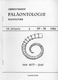
structures and data on composition (Fig. 2.1). Some<br />
commonly used descriptive terms for these coarse<br />
gra<strong>in</strong>ed sedimentary rocks are:<br />
Diamictite: a non-genetic term referr<strong>in</strong>g to any<br />
poorly sorted, terrigenous, generally non-calcareous,<br />
clast-sand-mud admixture regardless of depositional<br />
environment.<br />
Breccia: a term used when the majority of the clasts<br />
are angular (<strong>in</strong> the sense of Section 2.2.2).<br />
Extraformational: a term to describe clasts from<br />
source rocks outside the bas<strong>in</strong> of deposition.<br />
Intraformational: a term to describe clasts from<br />
fragmentation processes that take place with<strong>in</strong> the<br />
bas<strong>in</strong> of deposition and that are contemporaneous<br />
with sedimentation.<br />
Oligomict: a term to describe conglomerates where<br />
one clast type, usually of stable, resistant material, is<br />
dom<strong>in</strong>ant.<br />
Polymict (petromict): a term to describe conglomerates<br />
where several clast types are present.<br />
Description can be enhanced by us<strong>in</strong>g the dom<strong>in</strong>ant<br />
clast size and clast type as prefixes, e.g. granite<br />
boulder conglomerate. A special series of terms is<br />
used where volcanic processes are <strong>in</strong>volved <strong>in</strong> conglomerate<br />
formation (Lajoie, 1984).<br />
Further <strong>in</strong>formation on the sedimentary structures<br />
present <strong>in</strong> conglomerates can be conveyed by<br />
use of the concise lithofacies codes as developed by<br />
Miall (1977, 1978), Rust (1978) and Eyles, Eyles &<br />
Miall (1983) (Table 2.2). Although these have been<br />
developed specifically for alluvial fan, fluvial and<br />
glacial lithofacies, there is every likelihood that they<br />
will and can be used for all conglomerates. These<br />
http://jurassic.ru/<br />
1 Sort<strong>in</strong>g size distribution<br />
COLLECTION AND ANALYSIS OF FIELD DATA 7<br />
Clast supported Clast supported Matrix supported<br />
bimodal polymodal polymodal<br />
matrix well sorted matrix poorly sorted<br />
2 Fabric Flow Flow<br />
a (p) a (i) a (t) b (i) Unordered fabric<br />
3 Stratification<br />
O O O O O C O £) O<br />
OCxZ>& O<br />
O
8 J. GRAHAM<br />
(a) Criteria used for low s<strong>in</strong>uosity and glaciofluvial stream deposits (modified Table 2.2. Use of concise lithofacies<br />
from Miall, 1977) codes <strong>in</strong> field description<br />
Code Lithofacies Sedimentary structures<br />
Gms Massive, matrix- None<br />
supported gravel<br />
Gm Massive or crudely Horizontal bedd<strong>in</strong>g, imbrication<br />
bedded gravel<br />
Gt Gravel, stratified Trough crossbeds<br />
Gp Gravel, stratified Planar crossbeds<br />
St Sand, medium to Solitary (theta) or grouped (pi) trough<br />
coarse, may be crossbeds<br />
pebbly<br />
Sp Sand, medium to Solitary (alpha) or grouped (omicron)<br />
coarse, may be planar crossbeds<br />
pebbly<br />
Sr Sand, very f<strong>in</strong>e to Ripple marks of all types<br />
coarse<br />
Sh Sand, very f<strong>in</strong>e to very Horizontal lam<strong>in</strong>ation, part<strong>in</strong>g or<br />
coarse, may be stream<strong>in</strong>g l<strong>in</strong>eation<br />
pebbly<br />
SI Sand,f<strong>in</strong>e Low angle (10°) crossbeds<br />
Se Erosional scours with Crude crossbedd<strong>in</strong>g<br />
<strong>in</strong>traclasts<br />
Ss Sand, f<strong>in</strong>e to coarse, Broad, shallow scours <strong>in</strong>clud<strong>in</strong>g eta<br />
may be pebbly cross-stratification<br />
Sse, She, Spe Sand Analogous to Ss, Sh, Sp<br />
Fl Sand, silt, mud F<strong>in</strong>e lam<strong>in</strong>ation, very small ripples<br />
Fsc Silt, mud Lam<strong>in</strong>ated to massive<br />
Fcf Mud Massive with freshwater molluscs<br />
Fm Mud, silt Massive, dessication cracks<br />
Fr Silt, mud Rootlet traces<br />
C Coal, Carbonaceous Plants, mud films<br />
mud<br />
P Carbonate Pedogenic features<br />
(b) Diagnostic criteria for recognition of common matrix-supported diamict<br />
lithofacies (from Eyles et al., 1983)<br />
Code Lithofacies Description<br />
Dmm Matrix-supported, Structureless mud/sandVpebble<br />
massive admixture<br />
Dmm(r) Dmm with evidence of Initially appears structureless but<br />
resedimentation careful clean<strong>in</strong>g, macro-section<strong>in</strong>g, or<br />
X-ray photography reveals subtle<br />
textural variability ahd f<strong>in</strong>e structure<br />
(e.g. silt or clay str<strong>in</strong>gers with small<br />
flow noses). Stratification less than<br />
10% of unit thickness<br />
http://jurassic.ru/<br />
schemes are still be<strong>in</strong>g ref<strong>in</strong>ed and modified (cf.<br />
Eyles et al., 1983 with McCabe, Dardis & Hanvey,<br />
1984 and Shultz, 1984) and the overlap between the<br />
COLLECTION AND ANALYSIS OF FIELD DATA 9<br />
Code Lithofacies Sedimentary structures<br />
Dmm(c) Dmm with evidence of Initially appears structureless but<br />
current rework<strong>in</strong>g careful clean<strong>in</strong>g, macro-section<strong>in</strong>g,<br />
or textural analysis reveals f<strong>in</strong>e<br />
structures and textural variability<br />
produced traction current activity<br />
(e.g. isolated ripples or ripple tra<strong>in</strong>s).<br />
Stratification less than 10% of unit<br />
thickness<br />
Dmm(s) Matrix-rupported, Dense, matrix supported diamict with<br />
massive, sheared locally high clast concentrations.<br />
Presence of dist<strong>in</strong>ctively shaped flatiron<br />
clasts oriented parallel to flow<br />
direction, sheared<br />
Dms Matrix-supported, Obvious textural differentiation or<br />
stratified diamict structure with<strong>in</strong> diamict.<br />
Stratification more than 10% of unit<br />
thickness<br />
Dms(r) Dms with evidence of Flow noses frequently present; diamict<br />
resedimentation may conta<strong>in</strong> rafts of deformed<br />
silt/clay lam<strong>in</strong>ae and abundant<br />
silt/str<strong>in</strong>gers and rip-up clasts. May<br />
show slight grad<strong>in</strong>g. Dms(r) units<br />
often have higher clast content than<br />
massive units; clast clusters common.<br />
Clast fabric random or parallel to<br />
bedd<strong>in</strong>g. Erosion and <strong>in</strong>corporation<br />
of underly<strong>in</strong>g material may be<br />
evident<br />
Dms(c) Dms with evidence of Diamict often coarse (w<strong>in</strong>nowed)<br />
current rework<strong>in</strong>g <strong>in</strong>terbedded with sandy, silty and<br />
gravelly beds show<strong>in</strong>g evidence of<br />
traction current activity (e.g. ripples,<br />
trough or planar cross-bedd<strong>in</strong>g). May<br />
be recorded as Dmm, St, Dms, Sr<br />
etc. accord<strong>in</strong>g to scale of logg<strong>in</strong>g.<br />
Abundant sandy str<strong>in</strong>gers <strong>in</strong> diamict.<br />
Units may have channelized bases<br />
Dmg Matrix-supported, Diamict exhibits variable vertical<br />
graded grad<strong>in</strong>g <strong>in</strong> either matrix or clast<br />
content; may grade <strong>in</strong>to Dcg<br />
Dmg(r) Dmg — with evidence Clast imbrication common<br />
of resedimentation<br />
D (diamictite) and G (gravel) codes needs further<br />
clarification. The codes should not be regarded as all<br />
that is needed for environmental <strong>in</strong>terpretation
10 J. GRAHAM<br />
(Dreimanis, 1984; Kemmis & Hallberg, 1984) but<br />
simply a concise and convenient shorthand description<br />
of some of the ma<strong>in</strong> observable features.<br />
In addition to <strong>in</strong>formation on depositional processes<br />
and environments, polymict conglomerates<br />
can yield some <strong>in</strong>formation on the relative contribution<br />
of various source lithologies. However, there<br />
are many factors which affect the presence and size<br />
of clasts <strong>in</strong> conglomerates. The <strong>in</strong>itial size of fragments<br />
released from the source area varies with<br />
lithology, be<strong>in</strong>g related to features such as bed thickness,<br />
jo<strong>in</strong>t spac<strong>in</strong>g and resistance to weather<strong>in</strong>g. In<br />
addition clasts have vary<strong>in</strong>g resistances to size reduction<br />
dur<strong>in</strong>g transport. To avoid spurious sizerelated<br />
effects, compositional data can be compared<br />
at constant size. This can be achieved either by<br />
count<strong>in</strong>g the clast assemblage for a given size class<br />
or by a more detailed analysis <strong>in</strong> which the proportion<br />
of clast types is exam<strong>in</strong>ed over a spectrum of<br />
size classes at a s<strong>in</strong>gle site.<br />
To determ<strong>in</strong>e the distribution of clast types by<br />
size, an area of several square metres should be<br />
chosen on a clean exposure surface on which all<br />
clasts can be identified easily. Areas of strong shape<br />
selection, common <strong>in</strong> some proximal fluvial and<br />
beach environments, should be avoided s<strong>in</strong>ce this<br />
can <strong>in</strong>troduce a bias towards anisotropic clast lithologies.<br />
Prelim<strong>in</strong>ary observations and the nature of<br />
the study will determ<strong>in</strong>e the number of lithological<br />
types to which clasts are assigned. Often crude discrim<strong>in</strong>ants,<br />
e.g. granite porphyry, etc., will suffice.<br />
More detailed studies require more subtle subdivision<br />
and may <strong>in</strong>volve th<strong>in</strong> section checks on field<br />
identification.<br />
Clast count<strong>in</strong>g should proceed from the f<strong>in</strong>est<br />
clast size <strong>in</strong>terval. It is important that all clasts are<br />
counted to elim<strong>in</strong>ate bias; repetition may be avoided<br />
by us<strong>in</strong>g chalk to mark counted clasts. As coarser<br />
size clasts are counted, the area over which clasts are<br />
counted may be <strong>in</strong>creased as a representative clast<br />
population (>100) is sampled. These data can be<br />
summarized by construct<strong>in</strong>g a plot of percentage<br />
clast types aga<strong>in</strong>st gra<strong>in</strong> size. The proportion of any<br />
clast type at a given gra<strong>in</strong> size can easily be read<br />
from the plot, allow<strong>in</strong>g direct comparison from<br />
locality to locality (Fig. 2.2). To present data from<br />
many localities, stratigraphic columns can be used to<br />
show changes <strong>in</strong> clast composition, or a map can be<br />
devised to show the regional distribution of clast<br />
types (Figs 2.3 and 2.4).<br />
Many published studies of clast composition are<br />
of limited value, either due to lack of specification of<br />
clast size or to problems of how the clasts to be<br />
measured were selected. Techniques of random<br />
selection of clasts <strong>in</strong>volve the plac<strong>in</strong>g of a sampl<strong>in</strong>g<br />
grid, for example chalked squares or a piece of fish<br />
net, over the exposure and measur<strong>in</strong>g either at grid<br />
<strong>in</strong>tersections or with<strong>in</strong> small grid squares. The former<br />
may be difficult to apply if only certa<strong>in</strong> sizes are<br />
accepted; the latter may <strong>in</strong>troduce bias if only a<br />
limited number of clasts per square are to be measured.<br />
It is important that the method of data collection<br />
is clearly stated so that its limitations can be<br />
assessed by later workers.<br />
LIMESTONES AND DOLOMITES<br />
Field dist<strong>in</strong>ction of carbonate rocks is possible, but<br />
detailed description is best performed <strong>in</strong> the laboratory<br />
us<strong>in</strong>g th<strong>in</strong> sections and acetate peels (Chapter<br />
4) although under favourable conditions the latter<br />
may be made <strong>in</strong> the field. Dilute 10% HC1 is a<br />
standard field aid. Whilst limestones will react vigorously,<br />
most dolomites will show little or no reaction<br />
unless they are powdered. The addition of Alizar<strong>in</strong><br />
red S <strong>in</strong> HC1 will sta<strong>in</strong> limestones but not dolomite<br />
(Chapter 4) and this can be used <strong>in</strong> the field. In<br />
addition many dolomites are yellow or brown<br />
weather<strong>in</strong>g, harder than limestones and may show<br />
poor fossil preservation. In sequences of alternat<strong>in</strong>g<br />
0 100 200 300 400 500<br />
Clast size (mm)<br />
Fig. 2.2. Plot of percentage clast types versus gra<strong>in</strong> size for<br />
one locality for a Lower Devonian fluvial conglomerate<br />
(diagram k<strong>in</strong>dly supplied by Peter Haughton, University of<br />
Glasgow). Key to clast types: GS = greenschist, LA =<br />
lithic arenite, VQ = ve<strong>in</strong> quartz, G = granite, Vv =<br />
vesicular volcanics, V = other volcanics, O = other.<br />
http://jurassic.ru/<br />
Carboniferous<br />
• Lavas;<br />
Lutites and carbonates<br />
COLLECTION AND ANALYSIS OF FIELD DATA 11<br />
Composition<br />
Clasts <strong>in</strong><br />
conglomerate<br />
\/ Lava /V/>l|<br />
, Lava s \'\<br />
\^iV i '<br />
OVX/^ si<br />
100<br />
Sandstone<br />
petrography<br />
Lithic-arenites<br />
derived from<br />
local lavas<br />
Sub-arkosic<br />
^ Q u a r t z<br />
f xarenite<br />
— Lithic<br />
— arenite<br />
Sub-lithic<br />
.arenite<br />
10<br />
Dalradian<br />
clasts<br />
Fig. 2.3. Diagram to show changes <strong>in</strong> clast composition with time for the Midland Valley of Scotland (from Bluck, 1984).<br />
GS = greenschist, G = granite, O = other. (Reproduced by permission of the Royal Society, Ed<strong>in</strong>burgh.)<br />
limestones and dolomites, the beds of dolomite are<br />
commonly more <strong>in</strong>tensely jo<strong>in</strong>ted and fractured than<br />
the beds of limestone.<br />
Limestones are classified accord<strong>in</strong>g to two well<br />
tried and tested schemes which, although designed<br />
for microscope work, can often be applied <strong>in</strong> the<br />
w<br />
GO<br />
m<br />
o<br />
c<br />
«<br />
CO<br />
"co<br />
Q<br />
c<br />
CD<br />
><br />
O<br />
i<br />
Q_<br />
O<br />
field. It is more likely that a field identification can<br />
be made us<strong>in</strong>g the classification of Dunham (1962),<br />
while later laboratory work can identify the constituent<br />
components through which the Folk (1962)<br />
classification may be applied. Even if a full identification<br />
is not possible, any recognizable allochem
1 2 J. GRAHAM<br />
5 km<br />
Contour <strong>in</strong>terval = 4%<br />
Based on 110 pebble counts,<br />
100 pebbles per count<br />
Fig. 2.4. Regional distribution of gabbro pebbles <strong>in</strong> the Solund Conglomerate, Devonian, Norway (from Nilsen, 1968).<br />
(Reproduced by permission of Norges Geologiske Undersokelse.)<br />
type or fossil component should be recorded. If the<br />
degree of weather<strong>in</strong>g is suitable, these can usually<br />
be determ<strong>in</strong>ed with a hand lens.<br />
EVAPORITES<br />
Evaporites are chemical sediments that have been<br />
precipitated from water follow<strong>in</strong>g the evaporative<br />
concentration of dissolved salts. Where these rocks<br />
are preserved at outcrop there is little difficulty <strong>in</strong><br />
field description and prelim<strong>in</strong>ary identification (see<br />
Kendall, 1984 for a recent review). However, because<br />
of their soluble nature, evaporites are frequently<br />
dissolved or replaced <strong>in</strong> the subsurface. It is<br />
thus important to be aware of the typical pseudomorphs<br />
of evaporites which can be recognized, e.g.<br />
cubic halite crystals. Replacement is commonly by<br />
calcite, quartz or dolomite. Collapse features are<br />
also common where dissolution has occurred and a<br />
careful check should be made where disrupted or<br />
brecciated horizons are found.<br />
MIXED LITHOLOGIES<br />
Lithologies which are essentially mixtures of other<br />
rock types are frequent <strong>in</strong> some successions. At<br />
present there seems to be little agreement on the<br />
nomenclature of admixtures. An objective and consistent<br />
procedure of labell<strong>in</strong>g these rocks whilst<br />
identify<strong>in</strong>g the ma<strong>in</strong> and admix<strong>in</strong>g lithologies is<br />
necessary. The commonest admixtures are of siliciclastic<br />
and carbonate sediments and a textural and<br />
compositional classification for these has recently<br />
been proposed by Mount (1985).<br />
http://jurassic.ru/<br />
2.2.2 Texture<br />
GRAIN SIZE<br />
Because the determ<strong>in</strong>ation of gra<strong>in</strong> size is basic to<br />
sedimentological fieldwork, it is fortunate that the<br />
grade scale proposed by Wentworth (1922) is now<br />
<strong>in</strong>ternationally accepted as a standard (see Chapter<br />
3 and Table 3.4). However, the choice of what to<br />
measure can be somewhat different for different<br />
parts of the grade scale. For conglomerates it is<br />
commonly maximum clast size that is measured,<br />
although it is advisable" to estimate modal size(s) as<br />
well. Techniques for measur<strong>in</strong>g maximum clast size<br />
have varied considerably among different workers,<br />
as shown <strong>in</strong> Table 2.3. In the absence of an accepted<br />
standard it is thus necessary to state how the measurement<br />
was made. The maximum size of clasts is<br />
used as a parameter partly because the measurement<br />
is easily made but also because of its known<br />
relationship to flow competence.<br />
For sandstone it is usually modal size which is<br />
estimated by means of visual comparison to a reference<br />
card or block. These reference sets are constructed<br />
either by glue<strong>in</strong>g sieved sand of each size<br />
3 mm<br />
30 mm<br />
0-1
14 J.GRAHAM<br />
Fig. 2.6. Graph for determ<strong>in</strong><strong>in</strong>g the size of sedimentary gra<strong>in</strong>s (from Chil<strong>in</strong>gar, 1982). Sand gra<strong>in</strong>s (or rock particles) are<br />
placed <strong>in</strong> the central part of the circle — light particles <strong>in</strong> the left chart and dark particles <strong>in</strong> the right chart — and compared<br />
with those on the graph us<strong>in</strong>g a hand lens. The numbers are used for notebook read<strong>in</strong>g. (Reproduced by permission of the<br />
American Geological Institute.)<br />
fraction on to an annotated card (e.g. Friend et al.,<br />
1976) or by plac<strong>in</strong>g sieved sand with<strong>in</strong> a series of<br />
depressions <strong>in</strong> a plastic ruler (e.g. Blatt, 1982 and<br />
Fig. 2.5). These reference sets must be small and<br />
durable. A similar approach for most sand sizes and<br />
f<strong>in</strong>er gravels has long been used by Soviet geologists<br />
(Chil<strong>in</strong>gar, 1982; Fig. 2.6). These charts can be<br />
easily fixed <strong>in</strong>to the field notebook.<br />
Gra<strong>in</strong> size of mudrocks is much more difficult to<br />
estimate <strong>in</strong> the field and it is probably unrealistic to<br />
attempt more than the determ<strong>in</strong>ation of whether silt<br />
exceeds clay or vice versa. This can be accomplished<br />
by us<strong>in</strong>g a comb<strong>in</strong>ation of hand lens and 'feel'.<br />
Nibbl<strong>in</strong>g a small piece of mudrock with the teeth can<br />
be a useful test. Lack of abrasion plus a generally<br />
greasy or soapy feel will suggest dom<strong>in</strong>ance of clay;<br />
a gritty abrasive feel <strong>in</strong>dicates the presence of silt<br />
grade quartz, of which some estimate may be possible<br />
with a powerful hand lens. In mudrocks where<br />
there is a regionally developed cleavage, the spac<strong>in</strong>g<br />
of cleavage planes may locally be a useful guide.<br />
GRAIN SHAPE<br />
Shape of sedimentary particles is a complex property<br />
such that there are even differences of op<strong>in</strong>ion<br />
as to what constitutes shape. It is taken here <strong>in</strong> the<br />
sense of Barrett (1980) as compris<strong>in</strong>g form, roundness<br />
and surface texture. Only aspects of the first<br />
two are normally observable <strong>in</strong> the field.<br />
Roundness is generally described by means of<br />
comparison to standard images which can be readily<br />
taped <strong>in</strong>to the field note book. It has been shown that<br />
there is considerable operator variation with these<br />
http://jurassic.ru/<br />
(Rosenfield & Griffiths, 1953; Folk, 1955) but nevertheless<br />
their use may serve to highlight problems<br />
requir<strong>in</strong>g more rigorous laboratory <strong>in</strong>vestigation.<br />
Similarly form (overall shape) is normally described<br />
by assign<strong>in</strong>g gra<strong>in</strong>s to one of the four major<br />
classes erected by Z<strong>in</strong>gg (1935) (Fig. 2.7). The<br />
parameter of form <strong>in</strong>cludes, but is not completely<br />
def<strong>in</strong>ed by, sphericity, the measure of approach of a<br />
particle to a sphere. It is also possible to use a visual<br />
comparison chart which comb<strong>in</strong>es the measures of<br />
roundness and sphericity (Powers, 1982; Fig. 2.8).<br />
Such <strong>in</strong>formation may help to <strong>in</strong>dicate features such<br />
as lithological control of particle shape, shape sort<strong>in</strong>g<br />
and depositional fabric.<br />
SORTING<br />
In the field degrees of sort<strong>in</strong>g are most commonly<br />
determ<strong>in</strong>ed for sandstones, usually by visual comparison<br />
with a number of standard images which can<br />
be taped <strong>in</strong>to the field note book (Fig. 2.9). Field<br />
estimation of sort<strong>in</strong>g <strong>in</strong> mudrocks is generally not<br />
possible. When study<strong>in</strong>g limestones and conglomerates<br />
the presence of clast or matrix support is important<br />
<strong>in</strong> description and classification, e.g. <strong>in</strong> the<br />
application of the Dunham nomenclature.<br />
FABRIC<br />
Fabric refers to the mutual arrangement of gra<strong>in</strong>s<br />
with<strong>in</strong> a rock, i.e. their orientation and pack<strong>in</strong>g.<br />
Fabrics may be produced dur<strong>in</strong>g sedimentation or<br />
by later tectonic processes. Careful measurement<br />
will generally allow this dist<strong>in</strong>ction. The commonest<br />
fabrics are those produced by the orientation of<br />
elongate particles such as fossils <strong>in</strong> limestones, discs,<br />
blades and rods <strong>in</strong> conglomerates. This alignment<br />
may def<strong>in</strong>e bedd<strong>in</strong>g or may provide evidence of<br />
palaeocurrent direction as <strong>in</strong> imbrication (Section<br />
2.3.2; Potter & Pettijohn, 1977). Fabrics also occur<br />
<strong>in</strong> f<strong>in</strong>er-gra<strong>in</strong>ed sedimentary rocks but are not always<br />
observable <strong>in</strong> the field.<br />
POROSITY AND PERMEABILITY<br />
It may be possible to make rough estimates of the<br />
amount and orig<strong>in</strong> of porosity and permeability <strong>in</strong><br />
the field even though accurate measurement is not<br />
possible. For example, one may note partially filled<br />
open<strong>in</strong>gs <strong>in</strong> fossils, or irregular channels formed by<br />
fractur<strong>in</strong>g, leach<strong>in</strong>g or alteration. However, there<br />
COLLECTION AND ANALYSIS OF FIELD DATA 15<br />
0.2<br />
Oblate (disc, tabular) Equant<br />
(spherical)<br />
Bladed<br />
Prolate<br />
(roller,<br />
rod-like)<br />
_l I I I ~i I l_l L_<br />
0.2 0.4 0.6 %<br />
Cfs<br />
di<br />
0.8<br />
i i i<br />
Fig. 2.7. Major shape classes of sedimentary particles _<br />
(after Z<strong>in</strong>gg, 1935). d s, a\, d L = shortest, <strong>in</strong>termediate and<br />
longest diameters respectively.<br />
are many problems such as lateral variability of<br />
porosity over small distances and the fact that surface<br />
samples may not be representative of the rock's<br />
average porosity.<br />
2.2.3 Colour<br />
This can an important attribute <strong>in</strong> the description of<br />
many sedimentary rocks. There are basically two<br />
methods of description. By far the most rapid and<br />
simple is the subjective impression of the geologist<br />
<strong>in</strong> the field. Whilst this may be adequate for some<br />
general surveys it does lack objectivity, for colour<br />
perception is known to vary considerably among<br />
workers. More objective is the use of a standard<br />
colour chart such as that published by the Geological<br />
Society of America (Goddard et al., 1975) based on<br />
the Munsell Colour System. The form and arrangement<br />
of the colour system are shown <strong>in</strong> Fig. 2.10.<br />
The first step is to determ<strong>in</strong>e the hue of the rock.<br />
There are 10 major hues (Fig. 2.10), each one<br />
divided <strong>in</strong>to 10 divisions. Thus 5P would refer to the<br />
mid-po<strong>in</strong>t of the purple hue, 10P to a hue mid-way<br />
between purple and purple-blue and 7.5P to a hue<br />
mid-way between these two. Number<strong>in</strong>g is clockwise<br />
as shown <strong>in</strong> Fig. 2.10. After this a value is selected<br />
from 1 to 9 with 1 be<strong>in</strong>g the darkest and 9 the
16 J. GRAHAM<br />
Very well<br />
sorted<br />
1<br />
Well<br />
sorted<br />
Moderately<br />
sorted<br />
Poorly<br />
sorted<br />
7<br />
Very poorly<br />
sorted<br />
Fig. 2.9. Sort<strong>in</strong>g images and standard terms (from Compton, 1962). The numbers <strong>in</strong>dicate the number of size classes<br />
<strong>in</strong>cluded by c. 80% of the material. The draw<strong>in</strong>gs represent sandstones seen with a hand lens. (Reproduced by permission<br />
ofWiley.)<br />
http://jurassic.ru/<br />
COLLECTION AND ANALYSIS OF FIELD DATA 17<br />
Fig. 2.10. The form and arrangement of the Munsell Colour System (from Goddard et al., 1975). See text for explanation.<br />
(Reproduced by permission of the Geological Society of America.)<br />
lightest (black to white when there is no hue). Also<br />
selected is a chroma which is a degree of colour<br />
saturation. These are given values from O (no colour<br />
saturation) to 6 for the most vivid colours. Thus a<br />
colour can be represented by a code such as 5P4/2 as<br />
well as a name — greyish-purple. Several standard<br />
colours are arranged on sheets <strong>in</strong> a small booklet<br />
which is taken <strong>in</strong>to the field and then visually compared<br />
with the rocks. Intermediates are estimated.<br />
2.2.4 Induration and degree of weather<strong>in</strong>g<br />
Although <strong>in</strong>duration (hardness) cannot be readily<br />
quantified, it may be useful to record the variation <strong>in</strong><br />
this property us<strong>in</strong>g the qualitative scheme below:<br />
Unconsolidated: Loose.<br />
Very friable: Crumbles easily between f<strong>in</strong>gers.<br />
Friable: Rubb<strong>in</strong>g with f<strong>in</strong>gers frees numerous<br />
gra<strong>in</strong>s. Gentle blow with hammer<br />
dis<strong>in</strong>tegrates sample.<br />
Hard: Gra<strong>in</strong>s can be separated from sample<br />
with a steel probe. Breaks easily when hit<br />
with hammer.<br />
Very hard: Gra<strong>in</strong>s are difficult to separate with a<br />
steel probe. Difficult to break with a<br />
hammer.<br />
Extremely hard: Sharp hard hammer blow required.<br />
Sample breaks across most gra<strong>in</strong>s.<br />
The degree of weather<strong>in</strong>g will be a complex function<br />
of lithology, topography, climate and vegetation.<br />
In particular <strong>in</strong> humid tropical regions there<br />
may be an extremely thick regolith and little available<br />
'fresh' bedrock. Some general comments on the<br />
nature and degree of weather<strong>in</strong>g are appropriate,<br />
especially where these may <strong>in</strong>fluence or restrict<br />
<strong>in</strong>terpretation.<br />
2.2.5 Bedd<strong>in</strong>g<br />
In descriptive terms, a bed is a layer that is sufficiently<br />
dist<strong>in</strong>ct from adjo<strong>in</strong><strong>in</strong>g layers. In genetic<br />
terms, a bed represents a depositional episode dur<strong>in</strong>g<br />
which conditions were relatively uniform. The ma<strong>in</strong><br />
problem is that these two def<strong>in</strong>itions do not always<br />
co<strong>in</strong>cide, lead<strong>in</strong>g to some contention over exactly<br />
what constitutes a bed.<br />
Campbell (1967) stated that dist<strong>in</strong>ction of beds<br />
depends on recognition of bedd<strong>in</strong>g surfaces produced<br />
dur<strong>in</strong>g periods of non-deposition or by an<br />
abrupt change of conditions. This is the concept of<br />
the 'sedimentation unit' (Otto, 1938) which has been
18 J. GRAHAM<br />
adopted by many later workers (e.g. Re<strong>in</strong>eck &<br />
S<strong>in</strong>gh, 1975; Coll<strong>in</strong>son & Thompson, 1982). Other<br />
workers follow the convention that beds are recognizably<br />
dist<strong>in</strong>ct strata that have some lithologic or<br />
structural unity (Pettijohn, 1975, p. 102). Campbell<br />
acknowledged that bedd<strong>in</strong>g surfaces (us<strong>in</strong>g his def<strong>in</strong>ition)<br />
might not be readily recognized or may<br />
appear to be discont<strong>in</strong>uous. Thus there can be different<br />
judgements of the positions, thicknesses and<br />
features of beds depend<strong>in</strong>g on which concept is<br />
followed. The problem can be demonstrated by<br />
exposures of turbidites <strong>in</strong> the Carboniferous of<br />
Morocco (Figs 2.11 and 2.12). Follow<strong>in</strong>g Otto (1938)<br />
or Campbell (1967), a 'bed' <strong>in</strong> Fig. 2.11 would be (1)<br />
+ (2), a turbidite, or (3), a hemipelagite; the bedd<strong>in</strong>g<br />
surfaces would be between (3) and (1) and<br />
between (2) and (3). However, <strong>in</strong> many examples<br />
the boundary between units (2) and (3) is not recognizable<br />
due either to low quality exposure or simply<br />
to a lack of lithological contrast between units (2)<br />
and (3). Here the 'beds' recognized may well be (1)<br />
and (2) + (3). Such ambiguity of description is<br />
clearly undesirable but at times difficult to avoid. In<br />
general the problems will be least where exposure is<br />
best and these are the areas <strong>in</strong> which detailed measurement<br />
is most likely to be made. However, the<br />
problem illustrates that there should be a consistent<br />
s<strong>in</strong>gle def<strong>in</strong>ition of a bed.<br />
The def<strong>in</strong>ition of a bed as a sedimentation unit,<br />
after Campbell (1967) and Re<strong>in</strong>eck & S<strong>in</strong>gh (1975)<br />
should be reta<strong>in</strong>ed, despite its problems. Assignment<br />
of a particular thickness limitation is not<br />
necessary; thicknesses may range from a few millimetres<br />
to several metres and can be described us<strong>in</strong>g<br />
the terms <strong>in</strong> Fig. 2.13. The ma<strong>in</strong> use of bed thickness<br />
measurements has been <strong>in</strong> help<strong>in</strong>g to estimate competence<br />
and capacity of the transport<strong>in</strong>g medium,<br />
particularly <strong>in</strong> terrestrial aqueous systems. For example,<br />
Bluck (1967), Steel (1974) and Nemec &<br />
Steel (1984) presented many plots of maximum particle<br />
size versus bed thickness and show that the<br />
relationship varies for different depositional processes<br />
(Fig. 2.14). Potter & Scheidegger (1965) suggested<br />
a correlation between maximum particle size<br />
and bed thickness <strong>in</strong> turbidites and between median<br />
clast diameter and bed thickness <strong>in</strong> ash falls. In all<br />
these cases <strong>in</strong>terpretation is clearly dependent upon<br />
the sedimentation unit concept for bed thickness.<br />
Thus if there is any uncerta<strong>in</strong>ty <strong>in</strong> the def<strong>in</strong>ition of<br />
High quality exposure Low quality exposure<br />
Ico<br />
L_<br />
2 I<br />
3 3, hemipelagic mud<br />
2<br />
I 2,turbidite mud<br />
1 \ . 1, turbidite sand<br />
Fig. 2.11. Recognition of beds with vary<strong>in</strong>g quality of<br />
exposure, an example from <strong>in</strong>terbedded turbidites and<br />
hemipelagites.<br />
Fig. 2.12. Interbedded turbidites and<br />
hemipelagites from the Lower<br />
Carboniferous of Morocco show<strong>in</strong>g<br />
rapid variation <strong>in</strong> exposure quality<br />
over short distances. Only the<br />
bedd<strong>in</strong>g surfaces at the base of<br />
turbidite sands (1) can be followed<br />
with any certa<strong>in</strong>ty.<br />
http://jurassic.ru/<br />
1000<br />
300<br />
100<br />
10<br />
Beds<br />
Very thick bed<br />
Thick bed<br />
Medium bed<br />
Th<strong>in</strong> bed<br />
Very th<strong>in</strong> bed<br />
30<br />
If 10<br />
E<br />
v> 3<br />
m<br />
CO<br />
* 1<br />
Lam<strong>in</strong>ae<br />
Very thick lam<strong>in</strong>a<br />
Thick lam<strong>in</strong>a<br />
Medium lam<strong>in</strong>a<br />
Th<strong>in</strong> lam<strong>in</strong>a<br />
Very th<strong>in</strong> lam<strong>in</strong>a<br />
Fig. 2.13. Term<strong>in</strong>ology for thickness of beds and lam<strong>in</strong>ae<br />
(modified after Ingram, 1954, Campbell, 1967 and<br />
Re<strong>in</strong>eck & S<strong>in</strong>gh, 1975). (Reproduced by permission of<br />
Spr<strong>in</strong>ger.)<br />
Fig. 2.14. Plots of maximum particle size (vertical axis)<br />
aga<strong>in</strong>st bed thickness (horizontal axis) show<strong>in</strong>g differences<br />
between different processes (from Steel, 1974) <strong>in</strong> the New .<br />
Red Sandstone of western Scotland. Locality: 1 — mudflow<br />
units, 2—stream flood conglomerates, 3 — braided<br />
stream conglomerates. All measurements <strong>in</strong> metres.<br />
(Reproduced by permission of SEPM.)<br />
COLLECTION AND ANALYSIS OF FIELD DATA 19<br />
bedd<strong>in</strong>g surfaces, this must be made very clear <strong>in</strong> the<br />
field notes. This problem may be particularly acute<br />
<strong>in</strong> many limestone successions where the bedd<strong>in</strong>g<br />
surfaces may show extreme diagenetic modification,<br />
usually accompanied by pressure solution and the<br />
formation of stylolites. Recognition is complicated<br />
because bedd<strong>in</strong>g parallel stylolitic seams may form<br />
at levels unrelated to true bedd<strong>in</strong>g surfaces (Simpson,<br />
1985). A summary of the complexity observed <strong>in</strong> a<br />
series of tabular limestone beds from the Lower<br />
Carboniferous of South Wales is shown <strong>in</strong> Fig. 2.15<br />
(after Simpson, 1985).<br />
A s<strong>in</strong>gle bed may be <strong>in</strong>ternally homogeneous,<br />
show cont<strong>in</strong>uous gradational variation, or be <strong>in</strong>ternally<br />
layered, these smaller layers be<strong>in</strong>g termed<br />
lam<strong>in</strong>ae. Lam<strong>in</strong>ae are generally a few millimetres<br />
thick but may exceptionally reach a few centimetres<br />
(Fig. 2.13). Beds may also show a variety of <strong>in</strong>ternal<br />
structures, such as types of cross stratification. It is<br />
common to f<strong>in</strong>d two superimposed beds that are<br />
0-15<br />
0-1 h<br />
0-05<br />
0<br />
0-5 1<br />
3. West Mull<br />
0-5
20 J. GRAHAM<br />
Layers def<strong>in</strong>ed by weather<strong>in</strong>g surfaces<br />
Co<strong>in</strong>cident with<br />
lithological changes<br />
and/or sedimentary<br />
structures<br />
Not co<strong>in</strong>cident with<br />
lithological changes<br />
and/or sedimentary<br />
structures<br />
Lithological changes<br />
and/or sedimentary<br />
structures absent<br />
Different lithologies<br />
Fig. 2.15. Complexity of depositional units (beds) and bedd<strong>in</strong>g parallel weather<strong>in</strong>g surfaces <strong>in</strong> limestones from the Lower<br />
Carboniferous of South Wales (from Simpson, 1985).<br />
related genetically and these are termed bedsets.<br />
They are called simple where the superimposed beds<br />
are similar and composite where they are different<br />
<strong>in</strong> appearance.<br />
The primary nature of contacts between beds and<br />
bedsets may be most important <strong>in</strong> environmental<br />
analysis. Any <strong>in</strong>formation which can be observed<br />
relat<strong>in</strong>g to the time span of non-deposition, e.g.<br />
burrowed surfaces, hardgrounds, soil formation,<br />
palaeokarsts, or evidence of erosional contacts<br />
should be carefully recorded.<br />
http://jurassic.ru/<br />
BED GEOMETRY<br />
Most description of bedd<strong>in</strong>g concentrates on the<br />
vertical changes <strong>in</strong> layered successions. Sedimentary<br />
layers usually do have a large lateral extent relative<br />
to their thickness, but it is, of course, f<strong>in</strong>ite. The<br />
three-dimensional geometry of beds and bedsets can<br />
yield very valuable <strong>in</strong>formation where it can be<br />
observed. Beds term<strong>in</strong>ate laterally by: (i) convergence<br />
and <strong>in</strong>tersection of bedd<strong>in</strong>g surfaces; (ii)<br />
lateral gradation of material compris<strong>in</strong>g the bed <strong>in</strong>to<br />
another <strong>in</strong> which bedd<strong>in</strong>g surfaces become <strong>in</strong>dist<strong>in</strong>guishable;<br />
(iii) abutt<strong>in</strong>g aga<strong>in</strong>st a fault, unconformity<br />
or cross cutt<strong>in</strong>g feature such as a channel.<br />
The way <strong>in</strong> which beds thicken and th<strong>in</strong> is important.<br />
For example channell<strong>in</strong>g is manifested by<br />
change <strong>in</strong> the position of the lower bedd<strong>in</strong>g surface<br />
whereas preserved bedforms such as ripples, dunes<br />
and hummocks are characterized by chang<strong>in</strong>g position<br />
of the upper bedd<strong>in</strong>g surface. It is important to<br />
measure the spac<strong>in</strong>g between such thickness changes<br />
to see if there is any pattern such as rhythmic spac<strong>in</strong>g.<br />
The relationship of <strong>in</strong>ternal structures to the external<br />
geometry is also important <strong>in</strong> <strong>in</strong>terpretation.<br />
Some beds can be del<strong>in</strong>eated with<strong>in</strong> a s<strong>in</strong>gle exposure<br />
whereas others may extend for tens or even<br />
hundreds of kilometres. The lateral extent can be<br />
useful <strong>in</strong> environmental dist<strong>in</strong>ction of superficially<br />
similar deposits, e.g. th<strong>in</strong> outer fan turbidites versus<br />
th<strong>in</strong> <strong>in</strong>terchannel turbidites of the upper fan, sheetflood<br />
versus fluvial channel deposits.<br />
2.2.6 Sedimentary structures<br />
The accurate recognition and record<strong>in</strong>g of sedimentary<br />
structures is vital to most attempts at environmental<br />
reconstruction. Description and <strong>in</strong>terpretation<br />
of such structures are the subject of several texts at<br />
various levels, e.g. Allen (1982), Coll<strong>in</strong>son &<br />
Thompson (1982), Conybeare & Crook (1968),<br />
Pettijohn & Potter (1964), Tucker (1982, chapter 5).<br />
These are not duplicated here but some comments<br />
on methods of record<strong>in</strong>g and recognition are appropriate.<br />
A list of the common structures and groups<br />
of structures classified predom<strong>in</strong>antly by position<br />
(after Pettijohn & Potter, 1964) is given <strong>in</strong> Table<br />
2.4.<br />
Almost all sedimentary structures are threedimensional,<br />
although recognition of many is based<br />
on observation of two-dimensional sections. The<br />
value of comment<strong>in</strong>g on the three-dimensional geo-<br />
COLLECTION AND ANALYSIS OF FIELD DATA 21<br />
Table 2.4. Sedimentary structures<br />
Observed primarily as <strong>in</strong>ternal structures of beds <strong>in</strong> section<br />
Cross stratification<br />
Lam<strong>in</strong>ation<br />
Grad<strong>in</strong>g<br />
Soft sediment deformation<br />
Bioturbation and trace fossils, stromatolites<br />
Pedogenic horizons, hardgrounds<br />
Cavities (ma<strong>in</strong>ly <strong>in</strong> limestones)<br />
Concretions<br />
Stylolites<br />
Observed primarily on bedd<strong>in</strong>g surfaces<br />
(i) Bottom surfaces:<br />
Flute marks<br />
Tool marks<br />
Load casts<br />
Geometry due to scour or topographic fill<br />
(ii) Top surfaces:<br />
Surface topography<br />
Bedforms, e.g. ripples, dunes, hummocks<br />
Primary current l<strong>in</strong>eation<br />
Shr<strong>in</strong>kage cracks<br />
Trace fossils<br />
Sand volcanoes<br />
Ra<strong>in</strong>drop impressions<br />
metry of any available structures cannot be overstated.<br />
It is always important to exam<strong>in</strong>e any exposed<br />
bedd<strong>in</strong>g surfaces as well as vertical sections. In<br />
record<strong>in</strong>g sedimentary structures reliance is placed<br />
both on objective observation and measurement and<br />
also on exist<strong>in</strong>g theoretical framework. Every field<br />
record of sedimentary structures will be a compromise<br />
between measur<strong>in</strong>g all basic and <strong>in</strong>disputable<br />
parameters on the one hand and us<strong>in</strong>g available<br />
classes of structures on the other hand.<br />
For example, many schemes for record<strong>in</strong>g crossstratification<br />
are so constricted that they imply that<br />
there are two basic types of cross-bedd<strong>in</strong>g — tabular<br />
and trough. If such a scheme was used to record<br />
cross stratification <strong>in</strong> a section conta<strong>in</strong><strong>in</strong>g hummocky<br />
cross stratification (HCS) (Fig. 2.16) then<br />
these would probably be recorded as trough cross<br />
strata, possibly with the lower angle of cross stratal<br />
dip noted. In this case the use of a limited theoretical<br />
framework leads to the amalgamation of HCS<br />
with cross strata of rather different orig<strong>in</strong>s and to the<br />
loss of valuable <strong>in</strong>formation. If data on angle of<br />
cross stratal dip and three-dimensional geometry of
22 J. GRAHAM<br />
0.5 m<br />
Fig. 2.16. Block diagram show<strong>in</strong>g the ma<strong>in</strong> features of hummocky cross stratification (HCS) (from Harms et al., 1982).<br />
Current directions unknown.<br />
the structures had been recorded, later <strong>in</strong>terpretation<br />
of the structures as HCS would rema<strong>in</strong> possible.<br />
How many examples of HCS can be confidently<br />
identified from pre-1965 publications? In spite of<br />
this the record<strong>in</strong>g of all parameters of cross strata <strong>in</strong><br />
every case would be too time consum<strong>in</strong>g.<br />
In most cases the available theoretical framework<br />
is used much more than is realized. Thus some<br />
general guidel<strong>in</strong>es are available for field record<strong>in</strong>g.<br />
(a) Be as familiar as possible with useful dist<strong>in</strong>ctions<br />
between the various sedimentary structures.<br />
If differences from a typical example of a<br />
particular structure are suggested it is better to<br />
over-divide than the reverse.<br />
(b) Remember that our knowledge is never complete.<br />
If the observed structures do not neatly fit<br />
any of our present theoretical pigeonholes,<br />
there is a need for objective and descriptive<br />
measurement.<br />
(c) Have a clear knowledge, preferably as a written<br />
record, of the range of variation accepted with<strong>in</strong><br />
any particular category of structure that is used.<br />
(d) If a suite of structures is relatively unfamiliar to<br />
you, although well known <strong>in</strong> general, carry summary<br />
diagrams or photographs <strong>in</strong> the field until<br />
familiarity is achieved.<br />
2.2.7 Fossil and trace fossil content<br />
Fossils are important components of many sedimentary<br />
rocks and, even where present <strong>in</strong> small numbers,<br />
they can provide useful, often critical, <strong>in</strong>formation.<br />
Extract<strong>in</strong>g the maximum <strong>in</strong>formation from fossils<br />
will usually require the services of a specialist<br />
palaeontologist. Nevertheless, important observations,<br />
particularly those useful for environmental<br />
rather than stratigraphic use, can and should be<br />
made by any <strong>in</strong>vestigator of sedimentary rocks. A<br />
useful checklist is given by Tucker (1982) (see also<br />
Table 2.5).<br />
Similarly, trace fossils and other biogenic structures<br />
provide valuable <strong>in</strong>formation. Biogenic structures<br />
vary from trace fossils possess<strong>in</strong>g a def<strong>in</strong>ite<br />
form that can be described and named, to rather<br />
vague disruptions or even complete homogenization<br />
of stratification. The latter can often only be described<br />
as bioturbation. Trace fossils can provide<br />
<strong>in</strong>formation on both palaeoecology and environment<br />
and may be especially valuable where body<br />
fossils are limited or absent. Description and classification<br />
of trace fossils utilize three ma<strong>in</strong> approaches:<br />
(a) Taxonomic: traces can be assigned to morphological<br />
ichnogenera. Details of this approach<br />
can be found <strong>in</strong> Crimes & Harper (1970), Frey<br />
(1975), Hantzschel (1975), Basan (1978) and<br />
Ekdale, Bromley & Pemberton (1984). A concise<br />
summary of a procedure to follow is given<br />
<strong>in</strong> Coll<strong>in</strong>son & Thompson (1982, chapter 9) (see<br />
also Table 2.6).<br />
(b) Tophonomic: description is based on mode of<br />
preservation of the trace fossils (Fig. 2.17).<br />
(c) Behavioural (ethological): subdivision is made<br />
on the <strong>in</strong>terpretation of behavioural pattern represented<br />
by the trace fossil, i.e. crawl<strong>in</strong>g,<br />
graz<strong>in</strong>g, rest<strong>in</strong>g, dwell<strong>in</strong>g, feed<strong>in</strong>g or escap<strong>in</strong>g.<br />
http://jurassic.ru/<br />
Table 2.5. Checklist for the exam<strong>in</strong>ation of fossils <strong>in</strong> the<br />
field<br />
Distribution of fossils <strong>in</strong> sediment<br />
(i) Fossils largely <strong>in</strong> growth position<br />
(a) Do they constitute a reef? — characterized by<br />
colonial organisms; <strong>in</strong>teraction between organisms, e.g.<br />
encrust<strong>in</strong>g growth; presence of orig<strong>in</strong>al cavities (<strong>in</strong>filled<br />
with sediment and/or cement); unbedded appearance:<br />
Describe growth forms of colonial organisms; do these<br />
change up through reef? Are some skeletons<br />
provid<strong>in</strong>g a framework?<br />
(b) If non-reef, are fossils epifaunal or <strong>in</strong>faunal?; if<br />
<strong>in</strong>faunal, how have fossils been preserved?<br />
(c) Do epifaunal fossils have a preferred orientation, if<br />
so, measure<br />
(d) Are fossils encrust<strong>in</strong>g substrate, i.e. is it a<br />
hardground surface?<br />
(e) Are the plant rema<strong>in</strong>s rootlets?<br />
(ii) Fossils not <strong>in</strong> growth position<br />
(a) Are they concentrated <strong>in</strong>to pockets, lenses or<br />
laterally persistent beds or are they evenly distributed<br />
throughout the sediment?<br />
(b) Do fossils occur <strong>in</strong> a particular lithofacies; are there<br />
differences <strong>in</strong> the faunal content of different lithofacies?<br />
(c) If fossil concentrations occur, what proportion of<br />
fossils are broken and disarticulated? Are delicate<br />
skeletal structures preserved? Check for sort<strong>in</strong>g, degree<br />
of round<strong>in</strong>g; look for sedimentary structures<br />
(d) Do fossils show a preferred orientation?, if so,<br />
measure<br />
(e) Have fossils been bored or encrusted?<br />
(f) Note the degree of bioturbation and any trace fossils<br />
present<br />
Fossil assemblagesand diversity<br />
(i) Determ<strong>in</strong>e the composition of the fossil assemblages by<br />
estimat<strong>in</strong>g the relative abundance of the different fossil<br />
groups.<br />
(ii) Are fossil assemblages different for different<br />
lithofacies?.<br />
(iii) Consider the composition of the fossil assemblage. Is<br />
it dom<strong>in</strong>ated by only a few species, are they euryhal<strong>in</strong>e or<br />
stenohal<strong>in</strong>e? Are certa<strong>in</strong> groups notably absent? Do all<br />
fossil groups present have a similar mode of life? Do<br />
pelagic forms dom<strong>in</strong>ate? Are <strong>in</strong>faunal organisms absent?<br />
Diagnesis of fossil skeletons<br />
(i) Is the orig<strong>in</strong>al m<strong>in</strong>eralogy preserved or have the<br />
skeletons been replaced, if so, by what?<br />
(ii) Have the fossils been dissolved out to leave moulds?<br />
(iii) Do the fossils preferentially occur <strong>in</strong> nodules?<br />
COLLECTION AND ANALYSIS OF FIELD DATA 23<br />
Table 2.6. Trace fossils: how to describe them and what to<br />
look for<br />
(1) Sketch (and/or photograph) the structures; measure<br />
length, width, diameter etc.<br />
(2) For trails and tracks: (seen on bedd<strong>in</strong>g surfaces)<br />
(a) Note whether regular or irregular pattern, whether<br />
trial is straight, s<strong>in</strong>uous, curved, coiled, meander<strong>in</strong>g or<br />
radial<br />
(b) Has the trail a cont<strong>in</strong>uous ridge or furrow?; is<br />
there any central division or ornamentation?; if there<br />
are appendage marks or footpr<strong>in</strong>ts measure the size<br />
and spac<strong>in</strong>g of the impressions; look for tail marks<br />
(3) For burrows (best seen with<strong>in</strong> beds but also on bedd<strong>in</strong>g<br />
surfaces):<br />
(a) Describe shape and orientation to bedd<strong>in</strong>g, i.e.<br />
horizontal, oblique, vertical; simple straight tube,<br />
simple curved or irregularly disposed tube. If<br />
branch<strong>in</strong>g note if regular or irregular branch<strong>in</strong>g<br />
pattern and any changes <strong>in</strong> burrow diameter<br />
(b) Exam<strong>in</strong>e burrow wall; is the burrow l<strong>in</strong>ed with<br />
mud or pellets?; are there scratch marks?; are lam<strong>in</strong>ae<br />
<strong>in</strong> adjacent sediment deflected by the burrow?<br />
(c) Exam<strong>in</strong>e the burrow fill; is it different from<br />
adjacent sediment?; e.g. coarser or f<strong>in</strong>er, richer or<br />
poorer <strong>in</strong> skeletal debris?; is the fill pelleted?; are<br />
there curved backfill lam<strong>in</strong>ae with<strong>in</strong> the burrow fill<br />
sediments?<br />
The last two approaches can usually be performed<br />
<strong>in</strong> the field without specialist knowledge. Taxonomic<br />
identification of common trace fossils is often possible<br />
but is best aided by accurate draw<strong>in</strong>gs and photographs<br />
and by consultation with specialists.<br />
2.2.8 Measurement of stratigraphic<br />
sections<br />
The methods employed <strong>in</strong> measur<strong>in</strong>g sections <strong>in</strong><br />
sedimentary rocks will be determ<strong>in</strong>ed by the degree<br />
of detail required, by the physical nature of the<br />
terra<strong>in</strong> and the exposures, and by the time, funds,<br />
equipment and personnel available. Details of the<br />
various procedures available are given <strong>in</strong> Compton<br />
(1962), Krumbe<strong>in</strong> & Sloss (1963) and Kottlowski<br />
(1965). In cases of suitable exposure measurement<br />
can be made simply by direct contact of a tape or<br />
ruler held normal to both dip and strike directions.<br />
Where this is feasible the most common method<br />
for measur<strong>in</strong>g vertical sections is probably the use of
24 J. GRAHAM<br />
Seilacher Bed<br />
Full relief<br />
Semirelief (epirelief)<br />
Full relief g •.<br />
Semirelief (hyporelief)<br />
Full relief<br />
a compass and tape measure. This is relatively quick<br />
and with care is sufficiently precise for most purposes.<br />
It is most difficult to be accurate where the<br />
dip of the strata is at a low angle to the section to be<br />
measured. The procedure is easier with two persons<br />
but can be performed by <strong>in</strong>dividuals. Important<br />
po<strong>in</strong>ts to note where the l<strong>in</strong>e of section is not at 90°<br />
to the dip of the beds are: (a) measure carefully the<br />
slope of the surface along with the strike and dip of<br />
the beds; (b) read the apparent thickness of beds,<br />
bedsets or facies units from the stretched tape (Fig.<br />
2.18); (c) correct for both slope angles and oblique<br />
sections (Fig. 2.19); (d) keep read<strong>in</strong>gs separate between<br />
changes of slope.<br />
In many cases where the beds are very steeply<br />
<strong>in</strong>cl<strong>in</strong>ed relative to the surface of measurement, the<br />
tape can be used as a small Jacob staff (see below)<br />
with reasonable accuracy, render<strong>in</strong>g the laborious<br />
corrections for slope unnecessary.<br />
An alternative to the use of a tape, where terra<strong>in</strong><br />
permits, is to use a graduated pole termed a Jacob<br />
staff (Fig. 2.20). The pole provides a steady support<br />
for a level or cl<strong>in</strong>ometer, an Abney hand level be<strong>in</strong>g<br />
the most accurate. The dip of the units to be measured<br />
is determ<strong>in</strong>ed and then this value is set on the<br />
Fig. 2.18. Measurement of strata on a slope by reference<br />
to a stretched tape. Note the projection of contact between<br />
units (2) and (3) to the tape (from Compton, 1962).<br />
(Reproduced by permission of Wiley.)<br />
Mart<strong>in</strong>sson<br />
Exichnia<br />
Epichnia<br />
(top of bed B)<br />
Endichnia<br />
(<strong>in</strong>terior of bed B)<br />
Hypichnia Fig. 2.17. A toponomic classification<br />
(bottom of bed B) rftrac£ fossils for u s e j n t h e field<br />
Exichnia (afterEkdaleefa/., 1984). (Reproduced<br />
(outside bed B) by permission of SEPM.)<br />
Strike of<br />
beds<br />
a. Slope and dip are opposed<br />
and angle of slope (y) plus<br />
angle of dip (x) is < 90°<br />
BC=AB s<strong>in</strong> (x+y)<br />
L<strong>in</strong>e of<br />
measurement<br />
b. Slope and dip are opposed<br />
and angle of slope plus angle<br />
of dip is > 90°<br />
BC=AB cos (x+y-90°)<br />
or BC=AB s<strong>in</strong> [180°-(x+y)]<br />
c. Slope and dip are <strong>in</strong> the<br />
same direction, with dip<br />
> slope<br />
AC=ABs<strong>in</strong> (x-y)<br />
d. Slope and dip are <strong>in</strong> the<br />
same direction, with dip<br />
< slope<br />
(b)<br />
BC=AB s<strong>in</strong> (y-x)<br />
AC=AB cos a<br />
Thickness<br />
Fig. 2.19. Corrections for slope angles and oblique<br />
sections (from Compton, 1962).<br />
(a) Correction of slope distance that was measured<br />
oblique to the dip of the beds.<br />
(b) Formulae used for various comb<strong>in</strong>ations of direction<br />
and amount of ground slope and dip of beds. (Reproduced<br />
by permission of Wiley.)<br />
http://jurassic.ru/<br />
(a)<br />
Horizontal<br />
ilane^<br />
COLLECTION AND ANALYSIS OF FIELD DATA 25<br />
Upper part -<br />
of Jacob staff<br />
1-5m<br />
Fig. 2.20. Use of the Jacob staff for measur<strong>in</strong>g sections (from Kottlowski, 1965).<br />
(a) Sett<strong>in</strong>g dip on cl<strong>in</strong>ometer of Abney hand level used with a Jacob staff.<br />
(b) Measur<strong>in</strong>g stratigraphic thickness AB.<br />
(c) Measur<strong>in</strong>g a unit with thickness less than the length of a Jacob staff.<br />
(Reproduced by permission of CBS.)<br />
cl<strong>in</strong>ometer (Fig. 2.20). The base of the staff is placed<br />
at the base of the unit to be measured and the staff<br />
tilted forward until the level bubble of the cl<strong>in</strong>ometer<br />
is centred. The l<strong>in</strong>e of sight is then <strong>in</strong> a direction<br />
parallel to the dip of the beds and the Abney level can<br />
be slid up and down the staff as required (Hansen,<br />
1960) until the top surface of the unit is <strong>in</strong> the l<strong>in</strong>e of<br />
sight (Fig. 2.20). If the staff is oriented with<strong>in</strong> 10° of<br />
normal to the dip, then the error is likely to be no<br />
more than 2% (Compton, 1962). Outcrops are rarely<br />
exposed <strong>in</strong> a straight upslope l<strong>in</strong>e but a stepwise<br />
course of movements can easily be made.<br />
2.2.9 Graphic logs<br />
The prime mov<strong>in</strong>g force beh<strong>in</strong>d the use of graphic<br />
logs <strong>in</strong> the field is the need to record very large<br />
numbers of observations, often <strong>in</strong> a rout<strong>in</strong>e repetitive<br />
manner. The first major formulation of such a<br />
scheme was presented by Bouma (1962) who demonstrated<br />
a successful application to a succession<br />
of turbidites. He used <strong>in</strong> the field a series of prepr<strong>in</strong>ted<br />
record<strong>in</strong>g sheets of the format shown <strong>in</strong> Fig.<br />
2.21. These were later supplemented by an accompany<strong>in</strong>g<br />
sheet based on laboratory <strong>in</strong>vestigations.<br />
However, the field record rema<strong>in</strong>ed as the f<strong>in</strong>al display,<br />
with the addgd laboratory data shown alongside.<br />
Bouma's record<strong>in</strong>g format was accompanied<br />
by a complex series of codes and notation symbols<br />
which permitted an unambiguous and detailed<br />
record.<br />
Broadly similar techniques have s<strong>in</strong>ce been employed<br />
by many other workers <strong>in</strong>vestigat<strong>in</strong>g a variety<br />
of sedimentary successions. Some examples of
26 J.GRAHAM<br />
Thickness (cm)<br />
Rock type<br />
Type<br />
Structures<br />
Current direction<br />
Coarse<br />
F<strong>in</strong>e<br />
Coarse<br />
Medium<br />
F<strong>in</strong>e<br />
Silt<br />
Very sandy<br />
Sandy<br />
Silty<br />
Clayey<br />
Carbonates<br />
Supplementary data<br />
Fossils<br />
Colour<br />
Induration<br />
Number of layer<br />
Units<br />
Remarks<br />
Gravel<br />
Sand<br />
Pelite<br />
Pelite<br />
O "O CD<br />
III<br />
CD (Q<br />
0)<br />
"O<br />
CD -<<br />
CD<br />
c<br />
CD O<br />
CO<br />
Fig. 2.21. Format for fieldTecord<strong>in</strong>g sheets designed by<br />
Bouma (Bouma, 1962). Field records are drawn to scale<br />
(chosen accord<strong>in</strong>g to the nature of the succession) and the<br />
sheets are accompanied by a complex set of notation<br />
symbols. (Reproduced by permission of Elsevier.)<br />
different record<strong>in</strong>g sheets are shown <strong>in</strong> Fig. 2.22.<br />
What are the reasons for this multiplicity of record<strong>in</strong>g<br />
sheets?<br />
(1) The features commonly recorded vary considerably<br />
with the type of succession, i.e. turbidites,<br />
fluvials, carbonates etc. If the broad nature of<br />
the succession is known <strong>in</strong> advance, there is an<br />
advantage <strong>in</strong> adapt<strong>in</strong>g the record<strong>in</strong>g form to the<br />
particular data to be recorded. This is usually<br />
the case for advanced, detailed studies that follow<br />
a reconnaissance exam<strong>in</strong>ation. An example<br />
of a complex but <strong>in</strong>formative scheme is that of<br />
the Utrecht school used <strong>in</strong> their studies of ancient<br />
marg<strong>in</strong>al-mar<strong>in</strong>e sediments <strong>in</strong> southwest<br />
Ireland (Kuijpers, 1972; Van Gelder, 1974; De<br />
Raaf, Boersma & Van Gelder, 1977; Fig. 2.22a).<br />
(2) One can ma<strong>in</strong>ta<strong>in</strong> at a higher level and for a<br />
longer period a discipl<strong>in</strong>e <strong>in</strong> the rout<strong>in</strong>e list<strong>in</strong>g of<br />
features than one can <strong>in</strong> a free-format notebook.<br />
Conversely, there may be some loss of<br />
flexibility, lead<strong>in</strong>g to a tendency for the field<br />
geologist to neglect features other than those on<br />
the check list.<br />
(3) Subsequent data retrieval is generally easier and<br />
more rapid than from written notebook records.<br />
(4) The use of a standard format can give greater<br />
consistency of record<strong>in</strong>g/observation where<br />
different operators are employed.<br />
(5) If the logs are drawn to scale <strong>in</strong> the field, the<br />
<strong>in</strong>vestigator has a useful visual display which<br />
may assist thought processes and the formulation<br />
of hypotheses.<br />
(6) There is often a tendency to th<strong>in</strong>k that the<br />
construction of a graphic log provides a complete<br />
description of a succession. In fact, vertical<br />
changes <strong>in</strong> the succession become over-emphasized<br />
at the expense of lateral relations.<br />
(7) There is a strong similarity between most field<br />
logs and the f<strong>in</strong>al published logs used <strong>in</strong> formation<br />
description and <strong>in</strong>terpretation.<br />
(8) Some sort of remarks column is <strong>in</strong>variably<br />
necessary to accommodate features which are<br />
rare or were neglected dur<strong>in</strong>g design of the<br />
form. Even with this, a field notebook rema<strong>in</strong>s a<br />
necessary aid for sketches etc. which cannot be<br />
accommodated on the record<strong>in</strong>g forms.<br />
A natural extension of graphic logs as the ma<strong>in</strong><br />
record<strong>in</strong>g technique was the attempt to design and<br />
use mach<strong>in</strong>e readable forms for field records<br />
(Alexander-Marrack, Friend & Yeats, 1970; Piper,<br />
http://jurassic.ru/<br />
Harland & Cutbill, 1970; Friend et al., 1976). The<br />
ma<strong>in</strong> advantages over and above the use of graphic<br />
logs were speed, rapid data retrieval and process<strong>in</strong>g,<br />
and easier data presentation, e.g. the data for computer-drawn<br />
stratigraphic sections are already stored<br />
<strong>in</strong> a retrievable form. The ma<strong>in</strong> disadvantage is the<br />
difficulty of build<strong>in</strong>g flexibility <strong>in</strong>to the form whilst<br />
ma<strong>in</strong>ta<strong>in</strong><strong>in</strong>g a manageable size and simplicity. Friend<br />
et al. (1976) demonstrated the value of this approach<br />
for record<strong>in</strong>g thick, relatively monotonous successions<br />
under difficult and expensive field conditions<br />
(Fig. 2.23).<br />
PRESENTATION OF GRAPHIC LOGS<br />
Graphic logs are used <strong>in</strong> a large proportion of<br />
publications deal<strong>in</strong>g with sedimentary rock successions<br />
but for appropriate reasons there is no standardization.<br />
Information must be presented on a<br />
variety of scales, and for a wide variety of facies<br />
associations. Even the basic unit of the logs may<br />
vary from be<strong>in</strong>g the bed or bedset to 'facies' which<br />
are def<strong>in</strong>ed either on the basis of a detailed field log<br />
or dur<strong>in</strong>g a pilot study. An attempt to provide a<br />
comprehensive scheme of notation and symbols to<br />
cover all eventualities may be either too limit<strong>in</strong>g for<br />
very detailed studies or too complex. Nevertheless<br />
there are many conventions which make comparison<br />
of different logs easier.<br />
Thickness is almost always the vertical scale and<br />
the horizontal scale is most frequently gra<strong>in</strong> size.<br />
Other features which can be readily presented are<br />
lithology, sedimentary structures and nature of contacts<br />
between units. Palaeocurrent data (Section<br />
2.3) and some other data on vertical sequences<br />
(Section 2.4) can be conveniently located at the side<br />
of these logs. Figure 2.24 shows a variety of typical<br />
examples.<br />
An overall aim <strong>in</strong> the presentation of logs should<br />
be that the reader has a good basis for comparison<br />
with the literature and the data on which to build<br />
prelim<strong>in</strong>ary <strong>in</strong>terpretations of depositional environments<br />
and time-dependent changes.<br />
2.2.10 Record<strong>in</strong>g lateral relations<br />
Lateral variability of rock units is often obvious<br />
where there are large natural or man-made exposures.<br />
In humid, temperate regions these are<br />
ma<strong>in</strong>ly cliff faces, road cuts and quarry sections <strong>in</strong><br />
COLLECTION AND ANALYSIS OF FIELD DATA 27<br />
shallowly dipp<strong>in</strong>g strata. Extensive strike sections<br />
also occur <strong>in</strong> steeply dipp<strong>in</strong>g strata on many foreshore<br />
sections and <strong>in</strong> recently glaciated areas. In<br />
arid areas with shallowly dipp<strong>in</strong>g strata, large lateral<br />
exposures are common. Description of lateral<br />
changes generally relies on the use of photo-mosaics<br />
supplemented by field sketches, use of b<strong>in</strong>oculars,<br />
exam<strong>in</strong>ation of accessible portions and, where possible,<br />
measur<strong>in</strong>g spaced vertical logs. If the exposure<br />
is accessible, plane table mapp<strong>in</strong>g can also be useful,<br />
e.g. Bluck (1981) (Fig. 2.25).<br />
For reports and publications it is more common to<br />
demonstrate lateral relations with l<strong>in</strong>e diagrams than<br />
with photographs although <strong>in</strong> some cases both approaches<br />
can be useful (e.g. Allen & Matter, 1982,<br />
fig. 7). This is often due to the difficulty of present<strong>in</strong>g<br />
photographs at a scale where they are clear but<br />
can still be accommodated with<strong>in</strong> the report format.<br />
This problem can also apply to l<strong>in</strong>e draw<strong>in</strong>gs and <strong>in</strong><br />
many journals pull outs are only rarely tolerated due<br />
to the expense of production. Some examples of the<br />
presentation of lateral variability are shown <strong>in</strong> Figs<br />
2.25 to 2.28.<br />
2.3 PALAEOCURRENT DATA<br />
2.3.1 Introduction<br />
Palaeocurrent data are those which provide <strong>in</strong>formation<br />
on the direction(s) of sediment transport <strong>in</strong><br />
the past. As such they are an important part of<br />
sedimentological analysis on a variety of scales from<br />
<strong>in</strong>dividual bedforms to the whole sedimentary bas<strong>in</strong>.<br />
The ma<strong>in</strong> categories of <strong>in</strong>terpretation which may<br />
result from analysis of palaeocurrent data are direction<br />
of palaeoslope, patterns of sediment dispersal,<br />
relationship of palaeocurrent direction to lithosome<br />
(Krumbe<strong>in</strong> & Sloss, 1963, p. 300) geometry and<br />
location of source area. Such <strong>in</strong>terpretations may<br />
have economic as well as academic applications when<br />
deal<strong>in</strong>g with phenomena such as washouts <strong>in</strong> coalfields<br />
or placer deposits.<br />
The subject of palaeocurrents and bas<strong>in</strong> analysis<br />
has been exhaustively treated by Potter & Pettijohn<br />
(1977). They emphasized that a variety of observations<br />
can contribute palaeocurrent data and these<br />
may be grouped <strong>in</strong>to two classes:<br />
(a) Properties which acquire directional significance<br />
only when mapped regionally. These consist of:
28 J.GRAHAM<br />
Sandstone<br />
facies<br />
Heterolithic<br />
facies<br />
Basic rock types<br />
[ W Sa Large-scale cross-stratified<br />
sandstone (bulk sand content<br />
95-100%)<br />
Evenly lam<strong>in</strong>ated sandstone<br />
(bulk sand content 95-100%)<br />
I\-"- \ Sc Small-scale cross-lam<strong>in</strong>ated<br />
sandstone<br />
(bulk sand content 95-100%)<br />
| Ha Sandy flaser bedd<strong>in</strong>g<br />
(bulk sand content 75-95%)<br />
Flaser bedd<strong>in</strong>g<br />
(bulk sandstone content 50-75%)<br />
i<br />
Hc1 Sand-lensed mud<br />
(bulk sand content 10-50%)<br />
Hc2 Sand-streaked mud<br />
(bulk sand content 10-50%)<br />
Mudstone _ ^, Mudstone<br />
facies (bulk sand content 0-10%)<br />
(a)<br />
— c<br />
to o<br />
CO «< «
30 J. GRAHAM<br />
(b)<br />
Section log<br />
Sheet no.<br />
Cumthick<br />
Lithology<br />
Geologist<br />
Date(s)<br />
(i) attributes — presence/absence of some dist<strong>in</strong>ctive<br />
feature such as boulder type or m<strong>in</strong>eral<br />
assemblage; (ii) scalars — magnitude of some<br />
property such as gra<strong>in</strong> size, roundness or unit<br />
thickness.<br />
In these cases there is little extra record<strong>in</strong>g of<br />
field data but merely a selection of specific properties<br />
from available records. Accord<strong>in</strong>gly this<br />
class is given little treatment here apart from<br />
some examples.<br />
Properties which provide some directional <strong>in</strong>formation<br />
at the po<strong>in</strong>t of observation, although<br />
Locality<br />
Grid co-ord<strong>in</strong>ates<br />
from<br />
Altitude from | to<br />
Map sheet no.<br />
Aerial photo no.<br />
Locality no.<br />
Fossils,<br />
trace<br />
fossils<br />
Sample<br />
to<br />
more <strong>in</strong>formation will be conveyed by present<strong>in</strong>g<br />
many observations <strong>in</strong> map form. These<br />
directional properties can <strong>in</strong>dicate either: (i) a<br />
l<strong>in</strong>e of flow, e.g. primary current l<strong>in</strong>eation,<br />
groove marks, symmetrical ripple crests or (ii) a<br />
unique direction of flow, e.g. imbrication, cross<br />
stratification, flute marks.<br />
Directional properties form the basis of most<br />
palaeocurrent analysis because of the greater<br />
amount of <strong>in</strong>formation they conta<strong>in</strong>.<br />
http://jurassic.ru/<br />
(0<br />
Location<br />
Sheets<br />
Cont<strong>in</strong>ues from.<br />
Cum<br />
thick<br />
Unit<br />
thick<br />
Pom, gra<strong>in</strong> size<br />
F<br />
clsls<br />
M C<br />
S SlGIC<br />
Rock<br />
type<br />
• Massive bedd<strong>in</strong>g<br />
• Flat bedd<strong>in</strong>g<br />
COLLECTION AND ANALYSIS OF FIELD DATA 31<br />
• Lam<strong>in</strong>ated bedd<strong>in</strong>g<br />
• Part<strong>in</strong>g l<strong>in</strong>eation<br />
= X-bedded v v = Mud cracks<br />
= X-lam<strong>in</strong>ated<br />
J<br />
W\J = Convoluted bedd<strong>in</strong>g<br />
= Trough v_/ = Channel<br />
= Tabular //// = Imbrication<br />
Erosive AA/\ Gradational Abrupt (not known -<br />
Sharp, non-erosive Deformed (load casts etc.) "\J^ if erosional)<br />
Structures L.B.S. Sort<strong>in</strong>g/<br />
round<br />
G = good M = moderate P = poor<br />
B = black Gr = green Lt = light<br />
G = grey P = purple Dk = dark D = dull<br />
Colour Uncorrected<br />
palaeo-<br />
Local<br />
bedd<strong>in</strong>g<br />
Undulat<strong>in</strong>g -<br />
Not seen<br />
Remarks (+ comp. of<br />
coarse clasts)<br />
PSL<br />
number<br />
Fig. 2.22. Examples of different record<strong>in</strong>g sheets.<br />
(a) A detailed and complex scheme devised specifically for marg<strong>in</strong>al mar<strong>in</strong>e sediments by De Raaf, Boersma, Leflef &<br />
Kuijpers (from Kuijpers, 1972).<br />
(b) A more general scheme for record<strong>in</strong>g vertical sequences <strong>in</strong> sedimentary successions designed for the Greenland<br />
Geological Survey by L.B. Clemmensen and F. Surlyk.<br />
(c) A scheme with a limited number of symbols and columns designed specifically for record<strong>in</strong>g large thicknesses of fluvial<br />
sediments (from Russell, 1984).<br />
2.3.2 Measurement of directional<br />
structures<br />
For each measurement it is important to record the<br />
exact location, type and scale of structure, as well as<br />
the lithofacies <strong>in</strong> which it occurs. For example, it<br />
may be useful to <strong>in</strong>vestigate the relationship of cross<br />
bedd<strong>in</strong>g direction to set thickness, foreset dip angle<br />
or foreset shape, as environmental <strong>in</strong>terpretation<br />
becomes more ref<strong>in</strong>ed.<br />
LINEAR STRUCTURES<br />
In this category are structures <strong>in</strong> which it is not<br />
possible to dist<strong>in</strong>guish between one 'end' of a structure<br />
and the other, e.g. primary current l<strong>in</strong>eation,<br />
striae, groove marks, gutter casts, channels, some<br />
oriented elongate fossils and symmetrical ripple<br />
crests. The orientation of the l<strong>in</strong>eation is recorded as<br />
a pitch on <strong>in</strong>cl<strong>in</strong>ed strata or <strong>in</strong> horizontal beds as a<br />
direction. Techniques for unambiguous record<strong>in</strong>g of
32 J.GRAHAM<br />
Station number Sheet number<br />
A B C D E F G H J K 10 20 _ 30 _ 40 ^ 50 60 70 80 -.90<br />
00<br />
100 200 300 400 500 600 700 800 900 0 1 2 3 4 5 6 ' 7 8 _ -. 9<br />
.<br />
0 2_<br />
__30<br />
3<br />
40<br />
0<br />
=:!:=<br />
2 4<br />
•0 •i .:?-. •4<br />
•00 | «_ EXPOSED COVERED<br />
4 5 6<br />
Thick<br />
(M)<br />
I<br />
70<br />
7<br />
SO<br />
_ 8 _<br />
90<br />
.. 6<br />
.- 7 _ .A.<br />
9 Write station and sheet numbers on stub<br />
NO CEM ROCK DOL<br />
CaC0 3 : : : : r<br />
FLAT SY.P AS.R PL.X TR.X<br />
7 •9 LIN DEF CONCR - C0 3ORSTUB FOSSILS NO VERT OTHR TR<br />
_RED F\RD _GY_ OTHER NO DIR | 2 DIR 1 DIR "00 100 200 300<br />
F.SL M.SL C.SL VF.SS F.SS_ M_SS C.SS VC.SS ?. 0N<br />
. PEBBLY 00 10 20 30 40 50 60 70 80 90<br />
GRAD SHP SMTH SCR TOOL MKS TR.FOS MD ;CR RIPPLES STUB-—SPEC RESTART 2 SPARE 4 CANC'L<br />
.9.<br />
1 2 .A 4<br />
-0 •1 •2 •3<br />
Thick<br />
•00 EXPOSED COVERED | _RED P.RD ^GN_<br />
5 _6_ 7 9 NO CEM ROCK DOL<br />
CaCO.1 :::::<br />
FLAT SY.P AS.R PL.X TR.X<br />
(M) •5 •6 •7 •9 LIN CONCR- COj OR STUB FOSSILS NO VERT OTHR TR<br />
-9.X.<br />
OTHER NO DIR 2 DIR 1 DIR 000 100 200 300<br />
F.SL M.SL C.SL VF.SS F.SS M.SS C.SS VC.SS CON PEBBLY 00 10 20 30 40 50 60 70 80 90<br />
GRAD SHP SMTH SCR TOOL | MKS TR.FOS. MD.CR RIPPLES STUB- -SPEC RESTART 1 SPARE<br />
—9..<br />
2 3<br />
:~=<br />
::::: Thick<br />
•0 •2 -3 •4<br />
(M)<br />
•00 EXPOSED COVERED<br />
1<br />
5 6 7 8 9 NO CEM<br />
K<br />
c»co3 ?S5 :<br />
f?i<br />
=!, CANC'L<br />
FLAT SY.P AS.R PL.X TR.X<br />
-5 •6 •7 •a 9 LIN CONCR- C0 3 OR STUB FOSSILS NO VERT OTHR TR<br />
RED P.RD GN GY OTHER NO DIR 2 DIR 1 DIR 000 100 200 300<br />
F.SL M.SL C.SL VF.SS F.SS M.SS C.SS^ VC.SS CON PEBBLY 00 10 20 30 40 50 60 70 80 90<br />
GRAD SHP SMTH SCR TOOL MKS. TR.FOS MD.CR RIPPLES STUB—SPEC RESTART 1 2 SPARE 4 CANC'L<br />
0<br />
•0<br />
__1. =<br />
==-.:=<br />
2 3 _ 4<br />
Thick<br />
5 6 7 B 9 NO CEM ROCK DOL<br />
CaC03, -zzz:<br />
FLAT SY.P AS.R PL.X TR.X<br />
•2 -3 •4 (M) •5 -6 -7 •8 •9 LIN CONCR-C0 3 OR STUf3 FOSSILS NO VERT OTHR TR<br />
Fig. 2.23. Example of a mach<strong>in</strong>e readable field record<strong>in</strong>g form (from Alexander-Marrack etal., 1970). This form was used<br />
for record<strong>in</strong>g thick, relatively monotonous fluvial successions <strong>in</strong> East Greenland (Friend et al., 1976) where fieldwork was<br />
expensive, time very limited and compatability among records from different <strong>in</strong>vestigators was important.<br />
Marks are made on the form with soft pencil and each form has an accompany<strong>in</strong>g stub on which additional notes can be<br />
made. (Reproduced by permission of Academic Press.)<br />
l<strong>in</strong>es and planes are given <strong>in</strong> texts such as Ragan<br />
(1973) and Compton (1962).<br />
CROSS-STRATIFICATION<br />
The most commonly used sedimentary structure for<br />
palaeocurrent analysis is cross stratification. The foresets<br />
represent the former slip faces of bedforms that<br />
migrated <strong>in</strong> the direction of foreset dip. The average<br />
direction of foreset dip is a measure of the average<br />
local flow direction. The geometrical variability of<br />
cross stratification mirrors the natural variability of<br />
bedforms. Although most workers categorize cross<br />
stratification <strong>in</strong> the two very broad subdivisions of<br />
planar and trough varieties (McKee & Weir, 1953;<br />
Section 2.2.4) there is, <strong>in</strong> nature, much more of a<br />
form cont<strong>in</strong>uum between these two (Meckel, 1967;<br />
Allen, 1982). The dimensions of the foresets will<br />
clearly be related to the size of the bedform, but this<br />
relationship is not simple. Commonly each foreset is<br />
truncated by an erosion surface, and thus the set<br />
thickness can only give a m<strong>in</strong>imum estimate of<br />
bedform height. Nevertheless set thickness is valuable<br />
<strong>in</strong>formation, important <strong>in</strong> the <strong>in</strong>terpretation of<br />
palaeoenvironmental conditions and must always be<br />
recorded. Similarly the angle of <strong>in</strong>cl<strong>in</strong>ation of the<br />
foresets is the result of a complex balance of factors<br />
such as gra<strong>in</strong> size, current velocity, sediment load<br />
etc., but it can still yield useful <strong>in</strong>formation on both<br />
the bedforms and transport processes. Thus the dip<br />
and shape of the foresets should also be recorded.<br />
The measurement of cross stratification is most<br />
simply accomplished where there is a reasonable<br />
degree of three-dimensional exposure. In these cases<br />
http://jurassic.ru/<br />
20-<br />
El<br />
MUOROCK<br />
coarse SANDY siltrock<br />
sandstone<br />
<strong>in</strong>traclasts<br />
[ =| flat beod<strong>in</strong>g<br />
cross beod<strong>in</strong>g<br />
j2^| ripple cross lam<strong>in</strong>ation<br />
f<strong>in</strong>e lam<strong>in</strong>ation<br />
fc-r-Ij AND / OR BIOTURBATION<br />
(a)<br />
35-<br />
25-<br />
20-<br />
10-+<br />
COLLECTION AND ANALYSIS OF FIELD DATA 33<br />
Legend<br />
Flaser f Bedd<strong>in</strong>g<br />
m.<br />
15<br />
mm<br />
Tabular cross-bedd<strong>in</strong>g Convolute bedd<strong>in</strong>g<br />
Trough cross-bedd<strong>in</strong>g<br />
Horizontal lam<strong>in</strong>ation<br />
Low-angle lam<strong>in</strong>ation<br />
Mud clasts<br />
i'sms Fl<strong>in</strong>t pebbles<br />
'' n i t e<br />
k'9<br />
' *<br />
^1] Ripple lam<strong>in</strong>ation<br />
js Lenticular "|<br />
1<br />
Roots<br />
6 Plant debris<br />
J Ophiomorpha<br />
~JT Burrows<br />
10H<br />
0<br />
(b)<br />
1 1 1 1 1 1 1<br />
ffl '<strong>in</strong> c n) at to ~<br />
sand<br />
Fig. 2.24. Examples of presentation styles of graphic logs.<br />
(a) Representative logs of the coarse gra<strong>in</strong>ed fluvial facies<br />
of the Upper Devonian Munster Bas<strong>in</strong>, Ireland show<strong>in</strong>g<br />
variation between proximal (A) and more distal (B) types.<br />
Lithology and structures are shown separately (from<br />
Graham, 1983).<br />
(b) Log of marg<strong>in</strong>al mar<strong>in</strong>e sediments from the Tertiary of<br />
South England display<strong>in</strong>g <strong>in</strong>ferred sequential organization<br />
as well as data on structures and trace fossils (from Pl<strong>in</strong>t,<br />
1983).
m<br />
55-<br />
50-<br />
45-<br />
40-<br />
35-<br />
30-<br />
25-<br />
20-<br />
15-<br />
10-<br />
Intraclast<br />
36 cm x 31 cm<br />
Intraclast<br />
24 cm<br />
. Above<br />
»S6 '<br />
\ BedZ<br />
"77-22<br />
Green Foresets<br />
\356° Below<br />
BedZ<br />
(c)<br />
the orientation of a foreset plane is measured directly<br />
with a compass/cl<strong>in</strong>ometer (along with any additional<br />
structural <strong>in</strong>formation as noted <strong>in</strong> Section<br />
2.3.3). Where such suitable exposure is lack<strong>in</strong>g, the<br />
true (maximum) foreset dip can be calculated by<br />
measur<strong>in</strong>g two apparent dips and solv<strong>in</strong>g by means<br />
of a stereographic projection.<br />
Measurement problems generally centre around<br />
the ability to dist<strong>in</strong>guish the three-dimensional geometry<br />
of the bedforms at outcrop. These problems<br />
may be compounded when the fill<strong>in</strong>g of troughs is<br />
asymmetrical. Thus it has been noted by several<br />
workers that trough axis orientations are much less<br />
variable than cross strata orientations (Meckel, 1967;<br />
Dott, 1973; Michelson & Dott, 1973; Sl<strong>in</strong>gerland &<br />
Williams, 1979) and are to be preferred for measurement.<br />
Unfortunately suitable exposures are only<br />
uncommonly available and less accurate approximations<br />
must generally be made. Careful record<strong>in</strong>g of<br />
the geometry of the structures on the measured<br />
faces is most important for subsequent <strong>in</strong>terpretation.<br />
Techniques for deriv<strong>in</strong>g palaeocurrent data from<br />
Green Foresets<br />
common exposure types have been suggested by<br />
^ Euestheria m<strong>in</strong>uta Von Zeiten Sl<strong>in</strong>gerland & Williams (1979) and De Celles, Long<br />
Vj|B ppssiblyhere<br />
ford & Schwartz (1983). One method suggested by<br />
Many Green,,,,. B e d z<br />
Foresets \ the latter is to attempt to measure both oppos<strong>in</strong>g<br />
fc<br />
trough limbs <strong>in</strong> relatively equal numbers on normal<br />
n-10<br />
oblique exposures. Plott<strong>in</strong>g these data on a stereo-<br />
Gravel passes<br />
graphic net should yield two clusters of oppos<strong>in</strong>g<br />
laterally to sand<br />
limb sets from which the trough axis orientation can<br />
fiSi* ?H Interclasts 15 m x 0-3 m I >" be estimated (Fig. 2.29). This technique may be<br />
. 0><br />
m useful for relatively flat ly<strong>in</strong>g strata but would be<br />
particularly susceptible to tectonic modification s<strong>in</strong>ce<br />
Green Foresets<br />
the plunge of undisturbed trough axes is commonly<br />
less than 10°.<br />
De Celles et al. (1983) also suggested a semiquantitative<br />
technique which relies on assess<strong>in</strong>g the<br />
overall geometry of the troughs by <strong>in</strong>spection of the<br />
foreset geometry relative to that of the basal scour<br />
surface, claim<strong>in</strong>g accuracy to with<strong>in</strong> 25° of the true<br />
palaeocurrent direction. The closer that a section<br />
approximates a true longitud<strong>in</strong>al section, the greater<br />
the apparent widen<strong>in</strong>g of the trough and the number<br />
of foresets that are truncated.<br />
(c) Log of Triassic fluvial sediments from central England<br />
which shows palaeocurrent data and comments on specific<br />
features of <strong>in</strong>terest. Assignment of particular beds and<br />
bedsets to def<strong>in</strong>ed lithofacies is shown to the left of the log<br />
(from Steel & Thompson, 1983).<br />
http://jurassic.ru/<br />
Fig. 2.25. A plane table map of an Upper Old Red Sandstone sand body from central Scotland and accompany<strong>in</strong>g section.<br />
Both lateral and vertical relations of bedforms are well demonstrated. CI, C2 etc. refer to lithofacies described <strong>in</strong> text, a, b,<br />
c refer to zones of facies <strong>in</strong>terf<strong>in</strong>ger<strong>in</strong>g and d to an area of soft sediment deformation (from Bluck, 1981). (Reproduced<br />
by permission of IAS.)<br />
Fig. 2.26. Field sketches of extensive motorway cutt<strong>in</strong>gs <strong>in</strong> shallowly dipp<strong>in</strong>g strata which demonstrate lateral relationships<br />
with<strong>in</strong> multistorey conglomerate channel bodies. Numbers refer to storeys: dense stipple -— overbank sandstones and<br />
mudstones; blank — channel sandstone and w<strong>in</strong>gs; diffuse stipple — conglomerate; SB 1 to 5 — sidebar units (from Allen<br />
et al., 1983). (Reproduced by permission of the Geological Society of London.)
£ 00<br />
o a<br />
o<br />
« D.<br />
•a E<br />
•8 °<br />
Q "a 3<br />
•- U 3 3<br />
a c "<br />
a- S<br />
3 £ a<br />
S = 2<br />
« c<br />
E a<br />
s<br />
O ° -5<br />
^ 2 "S<br />
9cd<br />
oo<br />
CL Ov<br />
D. _T<br />
2 U<br />
M 2<br />
00 °<br />
s -3<br />
o<br />
•a<br />
- _ o<br />
~ O ^ „.<br />
e 3 oo -o<br />
5 h _ o<br />
^ -a 3 2<br />
« . S | «<br />
b i S S<br />
o<br />
o<br />
E<br />
•s<br />
u<br />
T3 3<br />
13<br />
O O<br />
O S g-<br />
O £<<br />
c -<br />
s S- <br />
u<br />
E "<br />
•E o 1<br />
•s 1 I<br />
S •» E<br />
•a o a<br />
5 -c o<br />
5 a °<br />
—<br />
.2 ° M<br />
> j2 5<br />
•o<br />
oo<br />
en , J2<br />
http://jurassic.ru/<br />
Fig. 2.29. A method of estimat<strong>in</strong>g trough axes from<br />
measurements on trough limbs us<strong>in</strong>g a stereo net. Trough<br />
limb data show clusters of right hand (open circles) and left<br />
hand (closed circles) poles; average poles are <strong>in</strong>dicated by<br />
stars. The <strong>in</strong>tersection of the two correspond<strong>in</strong>g great<br />
circles (biplanar method) and the pole to the best fit great<br />
circle both give the trough axis (from De Celles etal.,<br />
1873). (Reproduced by permission of SEPM.)<br />
IMBRICATION AND CLAST ORIENTATION<br />
Ellipsoidal clasts frequently show a preferred alignment,<br />
particularly <strong>in</strong> coarse gra<strong>in</strong>ed sedimentary<br />
rocks. This alignment is visible <strong>in</strong> both plan view,<br />
here termed orientation, and <strong>in</strong> vertical sections,<br />
here termed imbrication. In some cases this alignment<br />
is due to the position of the clasts with<strong>in</strong><br />
structures such as foresets of cross strata. Here they<br />
show a similar downstream dip direction to the<br />
foresets but commonly a shallower <strong>in</strong>cl<strong>in</strong>ation<br />
(Johansson, 1965). In contrast the dip of the clasts<br />
not conta<strong>in</strong>ed <strong>in</strong> large foresets is preferentially upstream<br />
. Clearly the presence or absence of foresets<br />
<strong>in</strong> these coarse gra<strong>in</strong>ed rocks must be determ<strong>in</strong>ed at<br />
the outset. Several factors appear to control the<br />
range of <strong>in</strong>cl<strong>in</strong>ation <strong>in</strong>clud<strong>in</strong>g clast size, clast sphericity,<br />
degree of clast contact, and palaeohydraulic<br />
conditions (Johansson, 1965; Rust, 1975; Koster,<br />
Rust & Gendzwill, 1980). It has also been shown<br />
that the orientation of the longest a-axis (where<br />
a>b>c) tends to be either normal to or parallel to<br />
COLLECTION AND ANALYSIS OF FIELD DATA 37<br />
the flow direction, the difference depend<strong>in</strong>g <strong>in</strong> part<br />
on the nature of the flow. The former is the characteristic<br />
result of clasts roll<strong>in</strong>g on the bed (Johansson,<br />
1965; Rust, 1972) whereas the latter appears to be<br />
common only <strong>in</strong> conglomerates associated with<br />
sediment gravity flows (Walker, 1975), although the<br />
precise mechanism of formation is less clear.<br />
In sedimentary rocks the best measure of palaeocurrent<br />
direction is to obta<strong>in</strong> the mean vector of the<br />
ab pla'ne. The need to measure rod- or disc-shaped<br />
clasts <strong>in</strong>volves some selection, usually by means of<br />
ignor<strong>in</strong>g clasts more equant than say 2:2:1 (Rust,<br />
1975). The dip and strike of the ab plane is estimated<br />
by eye and measured from a notebook held <strong>in</strong> that<br />
plane. If the rocks are poorly <strong>in</strong>durated the clasts<br />
may be extracted after measurement and the orientation<br />
of the a-axis determ<strong>in</strong>ed. Application of this<br />
technique clearly requires good quality exposures.<br />
Random selection of clasts can be achieved by plac<strong>in</strong>g<br />
a sampl<strong>in</strong>g grid, e.g. a piece of fish net or chalk<br />
l<strong>in</strong>es, over the bedd<strong>in</strong>g surface. The stronger alignment<br />
of larger clasts which has commonly been<br />
observed (Johansson, 1965; Rust, 1972, 1975) may<br />
suggest that some selection <strong>in</strong> terms of size as well as<br />
shape is useful. The number of clasts to be measured<br />
should be such that a clear non-random distribution<br />
is achieved (Koster et al., 1980). Experience suggests<br />
that about 40 clasts is generally sufficient.<br />
In many cases the quality of exposure does not<br />
permit this technique of measurement. Where there<br />
is extensive bedd<strong>in</strong>g plane exposure but estimation<br />
of the dip of ab plane is difficult, a technique for<br />
measurement 'described by Nilsen (1968) can be<br />
employed. The elongation directions of 50 randomly<br />
selected clasts with axial ratios 1.5:1 are measured.<br />
This technique can also be used with a photograph<br />
and overlay if preferred. Such orientation read<strong>in</strong>gs<br />
may not provide an unambiguous palaeocurrent<br />
direction as long axis orientation modes tend to be<br />
either current normal or current parallel. Thus the<br />
same technique must also be applied to measure<br />
imbrication on vertical sections. Where possible vertical<br />
sections either parallel to the long axis orientation<br />
or perpendicular to it or both have commonly<br />
been chosen (Nilsen, 1968; Davies & Walker, 1974;<br />
Fig. 2.30). Davies & Walker (1974), <strong>in</strong> a study of the<br />
deep water Cap Enrage Formation of Quebec, noted<br />
that most of the available sections were fortuitously<br />
oriented parallel to modal clast orientation and that<br />
orthogonal faces had an <strong>in</strong>cl<strong>in</strong>iation not significantly<br />
different from horizontal compared to a mean of 12°
38 J. GRAHAM<br />
Sample size<br />
50 30<br />
-i—i—i—^<br />
10<br />
Distribution of<br />
clasts <strong>in</strong> one<br />
PERCENT<br />
W<br />
typical example<br />
Distribution of<br />
vector means of<br />
Vector mean <strong>in</strong>dividual examples<br />
Clasts parallel<br />
to bedd<strong>in</strong>g<br />
Plan view<br />
orientation<br />
Fig. 2.30. Block diagram show<strong>in</strong>g clast orientation <strong>in</strong> plan view (face A), imbrication (face B) and clasts parallel to bedd<strong>in</strong>g<br />
(face C). Solid rose diagrams show the distribution of vector means of <strong>in</strong>dividual examples and stippled rose diagrams show<br />
distribution of <strong>in</strong>dividual clast orientations <strong>in</strong> a typical example. Data are from the Cap Enrage Formation (deep water<br />
Cambro-Ordovician) of Quebec (from Davies & Walker, 1974). (Reproduced by permission of SEPM.)<br />
for the current parallel — <strong>in</strong> this case long axis<br />
parallel — sections. Thus they were able to obta<strong>in</strong> a<br />
statistical three-dimensional alignment.<br />
However, <strong>in</strong> many cases the available exposures<br />
may not be parallel to the palaeocurrent, and bedd<strong>in</strong>g<br />
plane exposures from which orientation can be<br />
estimated may also not be available. In these cases<br />
measurement is more difficult and less precise. It is<br />
necessary to measure imbrication on two faces, preferably<br />
40 J.GRAHAM<br />
Cwm Blithus Cwm-y-bont<br />
(b) WESTERN MARGIN<br />
R<strong>in</strong>g Hole<br />
n — RQ ""*"--*-AaL»—»-<br />
"axes<br />
Fold axes<br />
s Fold fac<strong>in</strong>g direction<br />
42 J.GRAHAM<br />
N<br />
Fig. 2.34. A worked example of reorientation of cross<br />
beds.<br />
Field record: Bedd<strong>in</strong>g (S) 040/40SE. Foreset (F) 010/48SE.<br />
Intersection l<strong>in</strong>eation pitches 30°NE on bedd<strong>in</strong>g. Plot the<br />
poles to the bedd<strong>in</strong>g (PS) and foreset (PF) as well as the<br />
bedd<strong>in</strong>g (S) and foreset (F) planes. Plot the <strong>in</strong>tersection<br />
l<strong>in</strong>eation (L).<br />
(1) Unfold by rotation about the fold axis (L) to position<br />
where dip = plunge (p). PS and PF move along great<br />
circles to PS' and PF' as S rotates about L. Position PS'<br />
determ<strong>in</strong>ed by L. PF Z. PF' = PS L PS'.<br />
(2) Rotate the bedd<strong>in</strong>g to the horizontal. Return PS' to<br />
the centre along small circle and move PF' the same angle<br />
along a small circle to PF". This is the pole of the orig<strong>in</strong>al<br />
foreset orientation (F 0). Read off the direction and amount<br />
of dip (25° to 040).<br />
Even for those sedimentologists who are clearly<br />
aware of structural limitations (e.g. Dott, 1974;<br />
McDonald & Tanner, 1983), there is seldom evidence<br />
that regional compression and fold style have<br />
been adequately considered. Unless considerable<br />
effort is spent <strong>in</strong> collect<strong>in</strong>g the necessary structural<br />
data, palaeocurrent analysis <strong>in</strong> rocks which have<br />
undergone significant shear and compression can at<br />
best be considered as approximate and at worst may<br />
be mislead<strong>in</strong>g.<br />
Several published palaeocurrent studies showed<br />
that reoriented foresets commonly showed <strong>in</strong>cl<strong>in</strong>ations<br />
much higher than the stable angle of repose of<br />
sand (Pelletier, 1958; Cassyhap, 1968). This is to be<br />
expected if the mechanisms of fold<strong>in</strong>g are considered<br />
(Ramsay, 1961, 1967). In flexural fold<strong>in</strong>g there is<br />
generally a systematic <strong>in</strong>crease <strong>in</strong> angle between the<br />
cross bedd<strong>in</strong>g and the regional bedd<strong>in</strong>g on one fold<br />
limb and a decrease <strong>in</strong> angle on the other limb.<br />
Where flexural fold<strong>in</strong>g is accompanied by compression<br />
normal to the axial plane the angle of <strong>in</strong>cl<strong>in</strong>ation<br />
of the cross bedd<strong>in</strong>g is further modifed. Abnormally<br />
high and low cross bedd<strong>in</strong>g <strong>in</strong>cl<strong>in</strong>ations are produced<br />
on both folded limbs (Fig. 2.35). The magnitude<br />
of the modifications is dependent on the radius<br />
of curvature of the base of the bed, the thickness of<br />
the cross bedded unit, the amount of dip of the<br />
bedd<strong>in</strong>g and the position of the foreset/regional<br />
bedd<strong>in</strong>g <strong>in</strong>tersection before fold<strong>in</strong>g. Most complex<br />
modifications result from the comb<strong>in</strong>ation of shear<br />
fold<strong>in</strong>g and compression. This can result <strong>in</strong> abnormally<br />
high or low <strong>in</strong>cl<strong>in</strong>ations on both fold limbs and,<br />
<strong>in</strong> the extreme case of the limbs of isocl<strong>in</strong>al folds, the<br />
structure may be completely unrecognizable.<br />
It is clear that the removal of tectonic effects from<br />
palaeocurrent read<strong>in</strong>gs can be laborious and timeconsum<strong>in</strong>g.<br />
Such a repetitive process is amenable to<br />
the application of computer techniques and some<br />
authors have advocated do<strong>in</strong>g this <strong>in</strong> the field with<br />
pocket calculators (Freeman & Pierce, 1979). A<br />
program that adequately considers both plunge and<br />
tilt removal is presented by Cooper & Marshall<br />
Fig. 2.35. Demonstration of the distortion of angles with<br />
flexural fold<strong>in</strong>g and compression.<br />
(a) Orig<strong>in</strong>al orientation of bedd<strong>in</strong>g with foresets <strong>in</strong>cl<strong>in</strong>ed<br />
at 30°.<br />
(b) The same bed subjected to flexural fold<strong>in</strong>g.<br />
(c) The same bed subjected to flexural fold<strong>in</strong>g and 50%<br />
compression.<br />
Note how abnormally high and low foreset dips can be<br />
generated depend<strong>in</strong>g on position with<strong>in</strong> the fold structure.<br />
(Reproduced by permission of McGraw-Hill.)<br />
http://jurassic.ru/<br />
(1981), who reviewed most earlier attempts. Such<br />
programs also frequently present the data <strong>in</strong> some of<br />
the standard formats outl<strong>in</strong>ed <strong>in</strong> the next section.<br />
These packages are now widely available and will<br />
probably be used <strong>in</strong>creas<strong>in</strong>gly <strong>in</strong> the future. Despite<br />
this some workers <strong>in</strong> structurally complex areas prefer<br />
to perform these operations by hand so that a<br />
careful check can be kept on the precision of each<br />
record<strong>in</strong>g (McDonald & Tanner, 1983). It is important<br />
to state clearly any manipulations that were<br />
performed and to note any likely limitations, such as<br />
not tak<strong>in</strong>g account of tectonic deformation.<br />
2.3.4 Presentation of data<br />
In a few cases where data are scarce but geologically<br />
significant, e.g. major channel orientations or giant<br />
cross beds (Coll<strong>in</strong>son, 1968), each palaeocurrent<br />
measurement may be shown <strong>in</strong>dividually. More<br />
normally, measurements are grouped <strong>in</strong>to classes of<br />
10°, 15°, 20° or 30°, the choice of <strong>in</strong>terval depend<strong>in</strong>g<br />
on both the number of read<strong>in</strong>gs and directional<br />
variability. In general, the lower the variability the<br />
smaller the class <strong>in</strong>terval although too small an<br />
<strong>in</strong>terval can lead to irregular class frequencies. These<br />
are presented <strong>in</strong> the form of a histogram converted<br />
to a circular distribution and termed a current rose<br />
(see Fig. 2.36). These histograms (roses) can plot<br />
either total number of observations per class or<br />
percentages, the latter often be<strong>in</strong>g useful for comparative<br />
purposes. In the geological literature the<br />
current rose conventionally <strong>in</strong>dicates the direction<br />
toward which the current moved.<br />
Although many structures used to <strong>in</strong>fer palaeocurrents<br />
are vectors, i.e. possess<strong>in</strong>g magnitude as<br />
well as direction, they are all usually considered as<br />
hav<strong>in</strong>g unit magnitude. This relates to the geological<br />
uncerta<strong>in</strong>ty of objectively assign<strong>in</strong>g a magnitude<br />
component. However, there are many cases where<br />
presentation of only standard current roses may lead<br />
to loss of valuable data. Thus amongst workers <strong>in</strong><br />
aeolian sediments it is common practice to present<br />
data on a polar stereographic projection (Reiche,<br />
1938; Kiersch, 1950; McKee, 1966; Carruthers, 1985;<br />
Fig. 2.37). Not only does this allow all read<strong>in</strong>gs to be<br />
shown <strong>in</strong>dividually but it also places visual emphasis<br />
on the larger dip angles as <strong>in</strong>dicators of palaeow<strong>in</strong>d<br />
directions. In addition Glennie (1970) has suggested<br />
the possibility that the type of dune structure can be<br />
recognized from the distribution of poles of dip<br />
planes.<br />
COLLECTION AND ANALYSIS OF FIELD DATA 43<br />
North-east<br />
region<br />
n = 120<br />
N<br />
4<br />
North region<br />
n = 258<br />
Fig. 2.36. Rose diagrams based on semi-octant classes of<br />
cross-stratal azimuths. Dotted l<strong>in</strong>es represent the<br />
partition<strong>in</strong>g <strong>in</strong>to two distributions for statistical analysis ,<br />
(from Kell<strong>in</strong>g, 1969). (Reproduced by permission of<br />
SEPM.)<br />
Most palaeocurrent studies are concerned with<br />
the preferred orientation direction, if one exists, and<br />
the degree of spread about that orientation. These<br />
are measures which are analogous to the means and<br />
variance of l<strong>in</strong>ear distributions but must be calculated<br />
differently to account for the circular nature of<br />
the data. The simplest form of calculation is:<br />
V = £" cos 6,<br />
W = E',' s<strong>in</strong> 9,<br />
x = arctan WIV,<br />
R = (v 2<br />
+ w 2<br />
y /2<br />
,<br />
L = (R/n). 100,<br />
0 = <strong>in</strong>dividual azimuth,<br />
n = number of read<strong>in</strong>gs,<br />
x = vector mean,<br />
R = magnitude of resultant vector,<br />
L = magnitude of resultant vector (%).<br />
R = R/n<br />
The values of L and n can be used for the Rayleigh<br />
test of significance outl<strong>in</strong>ed below.<br />
For two-dimensional orientation data such as<br />
primary current l<strong>in</strong>eation or goove casts, all orientations<br />
can be expressed with<strong>in</strong> a 180° range. In these<br />
cases the calculations become:<br />
V = Li cos 2 0,<br />
W = £" s<strong>in</strong> 2 9,
44 J. GRAHAM COLLECTION AND ANALYSIS OF FIELD DATA 45<br />
http://jurassic.ru/<br />
x = 1/2 arctan WIV,<br />
R = (w 2<br />
- V 2<br />
) 1<br />
' 2<br />
,<br />
L = (Rlri). 100.<br />
The vector mean (x) is an expression of preferred<br />
orientation whilst the vector magnitude (%) (L) is a<br />
sensitive measure of dispersion.<br />
It is necessary to test whether a set of palaeocurrent<br />
data possesses a distribution of orientation<br />
which is significantly different from random. Several<br />
ways of perform<strong>in</strong>g this test are reviewed by Potter<br />
& Pettijohn (1977, pp. 377-380). The simplest is<br />
probably the Rayleigh test as outl<strong>in</strong>ed by Curray<br />
(1956), for which a graph can be used (Fig. 2.38) to<br />
read the probability that the measurements are uniformly<br />
distributed <strong>in</strong> the <strong>in</strong>terval 0—360°. A desired<br />
level of significance, usually p < 0.05, is chosen at<br />
which the null hypothesis of a uniform distribution is<br />
rejected.<br />
The use of vector statistics <strong>in</strong> a comparable manner<br />
to the use of moments of a normal distribution<br />
implies the presence of a von Mises (circular normal)<br />
distribution of data. The density function of the von<br />
Mises distribution may be written as f(x) = jnI0(K) k c o s ( x _ e )<br />
(e<br />
1 0<br />
) where K is a parameter that expresses<br />
the concentration of the mass and 8 is the angle where<br />
the function takes its maximum value. I 0 (K) is a<br />
Bessel function whose values are tabulated. Such<br />
distributions are not always present as is often assumed,<br />
e.g. Sengupta & Rao (1966), although this<br />
can be readily checked by the method outl<strong>in</strong>ed by<br />
Harvey & Ferguson (1976).<br />
It is generally vector means which are presented<br />
<strong>in</strong> published data either on maps or accompany<strong>in</strong>g<br />
stratigraphic columns. "The number of read<strong>in</strong>gs and<br />
value of L (or R) should also be readily accessible. It<br />
is often useful to present some visual impression of<br />
the amount of confidence attached to a vector mean<br />
by show<strong>in</strong>g a confidence <strong>in</strong>terval (of, say, 90 or<br />
95%), e.g. Kell<strong>in</strong>g (1969). This can be most readily<br />
produced by us<strong>in</strong>g a Batschelet chart as shown <strong>in</strong><br />
Fig. 2.39. The techniques for calculat<strong>in</strong>g these confidence<br />
<strong>in</strong>tervals numerically from the raw data are<br />
given by Mardia (1972, pp. 144—145).<br />
It is also necessary to quantify the spread of values<br />
around the vector mean. For the von Mises distribution,<br />
R is an estimate of the spread of the angular<br />
values around a unit circle. The mean angular deviation,<br />
s, can be calculated by s = V(2(l — R)) where s<br />
is measured <strong>in</strong> radians. Although s behaves mostly<br />
20 50 100 200 400 600 800 1000 2000 4000 6000 10,000 20,000 40,000 60,000 100,000<br />
Number of observations, n<br />
Fig. 2.38. Rayleigh test of significance. The graph plots the probability of a given vector magnitude (L) occurr<strong>in</strong>g by<br />
chance for vary<strong>in</strong>g numbers of observations. A significance level is chosen, commonly p < 0.05, at which the hypothesis of a<br />
random distribution of orientations is rejected (from Curray, 1956). (Reproduced by permission of University of Chicago<br />
Press.)
46 J. GRAHAM<br />
0 0.1 0.2 0.3 0.4 6.5 0.6 0.7 0.8 0.9 1.0<br />
Length of mean vector R<br />
Fig. 2.39. Batschelet chart for obta<strong>in</strong><strong>in</strong>g a 95% confidence<br />
ipterval for the mean direction (from Batschelet, 1981).<br />
(Reproduced by permission of Academic Press.)<br />
<strong>in</strong> the same way as the standard deviation of a<br />
normal distribution, it is not its circular analogue<br />
which is K. Tables are available for convert<strong>in</strong>g R to<br />
K and <strong>in</strong>deed K is used <strong>in</strong> many further tests<br />
(Mardia, 1972).<br />
Hav<strong>in</strong>g obta<strong>in</strong>ed reliable estimates for preferred<br />
orientation and concentration of values some further<br />
tests may be desirable or possible depend<strong>in</strong>g on<br />
the nature of the problem. Perhaps the commonest<br />
problem is that of compar<strong>in</strong>g preferred current<br />
orientations for significant differences. Before advanc<strong>in</strong>g<br />
to test<strong>in</strong>g equality of mean directions it is<br />
necessary to test that the samples are drawn from<br />
populations with equal concentration (Mardia, 1972,<br />
pp. 158-62; Cheeny, 1983, pp. 102-103). The test<br />
for equality of preferred direction is somewhat complex<br />
as it depends <strong>in</strong> part on the ratio of the two<br />
sample sizes and also on the strength of the concentration<br />
parameter, K, of the samples comb<strong>in</strong>ed.<br />
Details and worked examples are given by Reyment<br />
(1971, pp. 48-50), Mardia (1972, pp. 152-155) and<br />
Cheeney (1983, pp. 101-106).<br />
Although vector statistics are both precise and<br />
powerful, it is clear that the underly<strong>in</strong>g populations<br />
of directional data must be thoroughly understood<br />
and def<strong>in</strong>ed. For example, sole marks and ripple<br />
marks from the bases and tops of beds could, <strong>in</strong> the<br />
case of storm-modified turbidites, represent different<br />
current systems operat<strong>in</strong>g at different times.<br />
Group<strong>in</strong>g of data and assumption of one population<br />
may be statistically possible but would not be geologically<br />
reasonable. Moreover the application of<br />
vector statistics implies a unimodal distribution and<br />
they are not directly applicable when the data are<br />
bimodal or polymodal. For this reason <strong>in</strong> particular<br />
current roses should always be drawn and the data<br />
<strong>in</strong>spected qualitatively.<br />
Some methods have been proposed for further<br />
treatment of bimodal and polymodal distributions.<br />
For example the problem of bimodality may be<br />
resolved by calculat<strong>in</strong>g separate vector means for<br />
two circular frequency distributions, the overlap<br />
be<strong>in</strong>g separated by partition about the midpo<strong>in</strong>t of<br />
the two shared classes conta<strong>in</strong><strong>in</strong>g the lowest frequencies<br />
(Fig. 2.36). This is possible where the two<br />
modes are almost opposite <strong>in</strong> direction but difficult<br />
to apply where they are closer together.<br />
For polymodal distributions where vector statistics<br />
are <strong>in</strong>appropriate, simpler, semi-quantitative techniques<br />
can be used to express preferred direction<br />
(Tanner, 1959; Picard & High, 1968; Fig. 2.40). A<br />
compass is divided <strong>in</strong>to 12 x 30° <strong>in</strong>tervals and the<br />
mean number of occurrences per <strong>in</strong>terval and the<br />
standard deviation are calculated. Those <strong>in</strong>tervals<br />
that conta<strong>in</strong> palaeocurrent directions <strong>in</strong> excess of<br />
one standard deviation above or below the mean<br />
represent prom<strong>in</strong>ent modes or nodes respectively.<br />
Intervals with<strong>in</strong> one standard deviation are considered<br />
to be qualitatively <strong>in</strong>dist<strong>in</strong>guishable from<br />
random distributions.<br />
2.3.5 Interpretation of results<br />
BEDFORM HIERARCHIES<br />
It has long been realized that sedimentary structures<br />
show an hierarchical arrangement such that no one<br />
sedimentary structure fully specifies a complex flow<br />
system. Such a specification can only be made after<br />
sampl<strong>in</strong>g all types of structure generated with<strong>in</strong> the<br />
limits of preservation. The concept of bedform hierarchies<br />
was formalized by Allen (1966), Bluck (1974)<br />
and Miall (1974) by whom parts of a fluvial system<br />
were given orders or ranks (Figs 2.41 and 2.42). In a<br />
general sense, the smaller structures <strong>in</strong> the hierarchy<br />
tend to be more variable because the currents form<strong>in</strong>g<br />
them are controlled both by the overall transport<br />
direction and also by local deviations caused by<br />
larger bedforms. This phenomenon is particularly<br />
well known from fluvial systems (Coll<strong>in</strong>son, 1968,<br />
http://jurassic.ru/<br />
COLLECTION AND ANALYSIS OF FIELD DATA 47<br />
10 15<br />
Fig. 2.40. Recognition of modes and nodes <strong>in</strong> polymodal<br />
distributions (see text for explanation) (from Picard &<br />
High, 1968). (Reproduced by permission of SEPM.)<br />
1971; Bluck, 1974; Miall, 1974) but also applies <strong>in</strong><br />
vary<strong>in</strong>g degrees to other environments (Field et al.,<br />
1981; L<strong>in</strong>k, Squires & Colburn, 1984). Thus one<br />
would be likely to regard the orientation of a s<strong>in</strong>gle<br />
channel form as be<strong>in</strong>g <strong>in</strong> some way more significant<br />
than the orientation of a s<strong>in</strong>gle set of trough cross<br />
<strong>in</strong>tegrated system<br />
Channel-form<br />
Po<strong>in</strong>t bar<br />
Large-scale ripples<br />
Small-scale ripples<br />
beds. There have been only a few attempts to quantify<br />
this difference <strong>in</strong> scale by <strong>in</strong>troduc<strong>in</strong>g a 'weight<strong>in</strong>g<br />
factor'. In many ways this is due to the difficulty<br />
of def<strong>in</strong><strong>in</strong>g an objective and operational methodology.<br />
Miall (1974) suggested us<strong>in</strong>g the cube of set<br />
thickness as it may crudely reflect the volume of<br />
sediment displaced by the current. Erosional loss of<br />
vary<strong>in</strong>g proportions of the sets clearly presents problems<br />
as do assumptions of geometrical similarity.<br />
Although this method has been little used it does<br />
qualitatively emphasize the differ<strong>in</strong>g significance that<br />
might be attached to different bedforms.<br />
It is sometimes possible to analyse or even sample<br />
palaeocurrent data with this concept of hierarchical<br />
organization <strong>in</strong> m<strong>in</strong>d (Olson & Potter, 1954; Potter<br />
& Olson, 1954; Kell<strong>in</strong>g, 1969). However, an assumption<br />
that chosen sampl<strong>in</strong>g levels (e.g. outcrops)<br />
will match any natural hierarchical level needs to be<br />
justified. An example of this is given by Kell<strong>in</strong>g<br />
(1969) who carefully sampled and analysed the<br />
palaeocurrents of some Upper Carboniferous fluvial<br />
• order one — order two<br />
Channel-form<br />
• order three — order four<br />
Large-scale<br />
ripples<br />
Small-scale<br />
ripples<br />
„rrfc<br />
1<br />
rrr<br />
Legend<br />
Channel-form<br />
Po<strong>in</strong>t bar<br />
Large-scale ripple<br />
crestl<strong>in</strong>es<br />
Small-scale ripple<br />
crestl<strong>in</strong>es<br />
Flow direction with<strong>in</strong><br />
flow-vector field<br />
Fig. 2.41. Hierarchical organizational of flow-vector fields <strong>in</strong> a fluvial system illustrat<strong>in</strong>g the dependence of currentdirectional<br />
data on rank of bedform (from Allen, 1966). (Reproduced by permission of Elsevier.)
48 J. GRAHAM<br />
Variability of orientation<br />
Fig. 2.42. Illustration of the possible relationships between flow stage, variability <strong>in</strong> orientation of structures and the k<strong>in</strong>d<br />
of sedimentary structures <strong>in</strong> a fluvial system. Ripples are often an exception because they tend to be caught <strong>in</strong> major<br />
channel troughs and orientated along them (from Bluck, 1974).<br />
sediments <strong>in</strong> South Wales. Sampl<strong>in</strong>g design followed<br />
a pilot study <strong>in</strong> a well-exposed area which gave some<br />
<strong>in</strong>dication of variability and m<strong>in</strong>imum number of<br />
measurements. The resultant data, summarized <strong>in</strong><br />
Fig. 2.43, show clearly the mean direction with confidence<br />
limits for each sample sector. An hierarchical<br />
analysis of variance at four different levels<br />
was also attempted and related to natural levels of<br />
variation <strong>in</strong> a river system, i.e.<br />
(i) different parts of dra<strong>in</strong>age net or different<br />
sources;<br />
(ii) different streams or portions of streams;<br />
(iii) deviations of laterally or vertically adjacent<br />
sand bodies with<strong>in</strong> major stream courses;<br />
(iv) divergence of superposed bedforms.<br />
More importantly, complementary data on the<br />
nature of the sedimentary structures (e.g. cross<br />
stratification type, set thickness, foreset dip angle)<br />
allow an objective assessment of the data by the<br />
reader.<br />
USE OF VARIABILITY IN<br />
ENVIRONMENTAL INTERPRETATION<br />
It can be seen from the above section that the<br />
amount of variability, even <strong>in</strong> a predom<strong>in</strong>antly unidirectional<br />
transport system, will depend <strong>in</strong> part on<br />
the level of bedform hierarchy which is sampled.<br />
Much of our knowledge of palaeocurrent variability<br />
comes from specific modern environments (Allen,<br />
1967; Miall, 1974). Attempts to dist<strong>in</strong>guish environments<br />
by means of the variance of their palaeocurrent<br />
pattern have been made by Potter & Pettijohn<br />
(1977) and Long & Young (1978) who tabulated<br />
large amounts of data from case histories. However,<br />
it should be remembered that modern environments<br />
record variability over a very short time period<br />
whereas most geological studies have data bases that<br />
are fundamentally different because the strata accumulated<br />
with an appreciable time dimension such<br />
that the group<strong>in</strong>g of data over a longer time <strong>in</strong>terval<br />
might be expected to <strong>in</strong>crease variance. More im-<br />
http://jurassic.ru/<br />
COLLECTION AND ANALYSIS OF FIELD DATA 49<br />
Fig. 2.43. An example of hierarchical sampl<strong>in</strong>g of palaeocurrent data from the Upper Carboniferous of South Wales. The<br />
map shows vector mean cross-stratal azimuths and 95% confidence limits for sectors and regions with<strong>in</strong> the study area<br />
(from Kell<strong>in</strong>g, 1969). (Reproduced by permission of SEPM.)<br />
portantly, the <strong>in</strong>equalities and uncerta<strong>in</strong>ties of timedependent<br />
changes and the difficulty of separat<strong>in</strong>g<br />
them from spatial variation make overall variance at<br />
best a very crude criterion.<br />
In specific studies it is possible and often desirable<br />
to exam<strong>in</strong>e variability of palaeocurrents <strong>in</strong> both time<br />
and space (e.g. Chisholm & Dean, 1974; Miall,<br />
1976; Picker<strong>in</strong>g, 1981; Gray & Benton, 1982),<br />
Variation <strong>in</strong> time generally <strong>in</strong>volves splitt<strong>in</strong>g vertical<br />
sections <strong>in</strong>to mean<strong>in</strong>gful subdivisions which can then<br />
be compared, e.g. by test<strong>in</strong>g whether their vector<br />
means are significantly different. Clearly this technique<br />
will be limited by the accuracy with which<br />
such subdivisions can be correlated.<br />
RELATIONSHIP OF SEDIMENTARY<br />
STRUCTURES TO ENVIRONMENT<br />
Although palaeocurrent data themselves can be important<br />
environmental discrim<strong>in</strong>ants, their full signi-<br />
ficance usually requires <strong>in</strong>dependent <strong>in</strong>terpretation<br />
of lithofacies and structures. It is particularly important<br />
<strong>in</strong> this respect that the structures that are measured<br />
<strong>in</strong> palaeocurrent analysis are described as<br />
thoroughly as possible. For example Bourgeois<br />
(1980) (Fig. 2.44) compared the dip amounts, as<br />
well as direction of, from HCS and trough cross beds<br />
and showed marked differences. In many earlier<br />
studies, written before the common recognition of<br />
HCS, such measurements would probably have been<br />
grouped as trough cross stratification. However if<br />
sufficient data were given on foreset <strong>in</strong>cl<strong>in</strong>ation the<br />
possible presence of HCS might be suggested and<br />
re-<strong>in</strong>vestigation stimulated.<br />
PALAEOCURRENT PATTERNS<br />
It has been noted on a more general scale that<br />
palaeocurrent data tend to form a set pattern when<br />
seen over appreciable areas. Potter & Pettijohn
50 J.GRAHAM<br />
Trough X-beds<br />
Mean<br />
ripple-crest<br />
orientation<br />
Hummocky beds<br />
Fig. 2.44. Comparison of dip direction (arrows) and dip angle of trough cross-beds and hummocky beds <strong>in</strong> the Cape<br />
Sebastian Sandstone, Cretaceous, Oregon. Dots are poles to cross bedd<strong>in</strong>g; dots with<strong>in</strong> the small circle represent dips less<br />
than 15° (from Bourgeois, 1980). (Reproduced by permission of SEPM.)<br />
(1977) suggested that, based purely on geometry,<br />
there are seven basic patterns (Fig. 2.45). Attempts<br />
have also been made to produce environmental<br />
classifications of palaeocurrent patterns,<br />
(e.g. by Selley, 1968) and also to relate these to<br />
geotectonic sett<strong>in</strong>g (e.g. by Potter & Pettijohn<br />
1977). At a smaller scale palaeocurrent data can<br />
support environmental discrim<strong>in</strong>ation suggested by<br />
other criteria. Thus Lam<strong>in</strong>g (1966) showed that<br />
palaeocurrents derived from strata <strong>in</strong>terpreted as<br />
aeolian have a totally different pattern from those<br />
<strong>in</strong>ferred to be fluvial. Chisholm & Dean (1974) used<br />
palaeocurrent data as the ma<strong>in</strong> evidence that parts<br />
of a largely fluvial Carboniferous formation <strong>in</strong> Scotland<br />
were deposited under the <strong>in</strong>fluence of tidal<br />
currents.<br />
Fluvial palaeocurrents, because of their basic control<br />
by gravity, tend to be unidirectional although<br />
with considerable spread over small areas (e.g.<br />
Leeder, 1973). Over larger areas it has been shown<br />
that major dra<strong>in</strong>age often occurs parallel to tectonic<br />
strike (Van Houten, 1974; Steel era/., 1977; Bluck,<br />
1978). Similar patterns have been shown to exist for<br />
deeper water mar<strong>in</strong>e sediments, particularly where<br />
there are submar<strong>in</strong>e fan systems present (Jipa, 1966;<br />
A «<br />
o ®<br />
OJ (D<br />
Ricci Lucchi, 1975b, 1981; McDonald & Tanner,<br />
1983).<br />
Aeolian current directions are typically <strong>in</strong>dependent<br />
of other terrestrial transport directions (e.g.<br />
Hubert & Mertz, 1984) and <strong>in</strong> favourable cases it<br />
may be possible to relate patterns to trade w<strong>in</strong>d<br />
circulation (e.g. Fryberger & Dean, 1979; Kocurek,<br />
1981). Shallow mar<strong>in</strong>e patterns are typically the<br />
most complex (Kle<strong>in</strong>, 1967) and difficult to <strong>in</strong>terpret.<br />
In the cases where the currents are of different<br />
types and with different controls it is particularly<br />
important to attempt to relate palaeocurrent data to<br />
the palaeoenvironmental <strong>in</strong>terpretation of the sedimentary<br />
structures from which they are derived.<br />
2.4 SEDIMENTARY FACIES AND<br />
SEQUENCE ANALYSIS<br />
2.4.1 Erection and use of facies<br />
Much of the field record<strong>in</strong>g of sedimentary rocks is<br />
aimed at classify<strong>in</strong>g the strata be<strong>in</strong>g <strong>in</strong>vestigated <strong>in</strong>to<br />
recurrent units and attempt<strong>in</strong>g to detect an order <strong>in</strong><br />
the vertical and lateral arrangement of those units.<br />
http://jurassic.ru/<br />
COLLECTION AND ANALYSIS OF FIELD DATA 51<br />
Parallel Convergent Divergent<br />
Curvel<strong>in</strong>ear Random Rotary<br />
Revers<strong>in</strong>g<br />
Fig. 2.45. Seven basic palaeocurrent patterns based on geometry (from Potter & Pettijohn, 1977). (Reproduced by<br />
permission of Spr<strong>in</strong>ger.)<br />
The term applied to these units is facies which are<br />
def<strong>in</strong>ed on a comb<strong>in</strong>ation of lithological, structural<br />
and organic aspects <strong>in</strong> the field. The facies may be<br />
given <strong>in</strong>formal designations, e^g. 'facies A' or brief<br />
descriptive designations, e.g. 'pebbly sandstone<br />
facies'. The ma<strong>in</strong> criteria used <strong>in</strong> delimit<strong>in</strong>g facies<br />
will vary with the strata be<strong>in</strong>g <strong>in</strong>vestigated. A facies<br />
unit may <strong>in</strong> some cases be an <strong>in</strong>dividual bed or<br />
bedset but may also comprise several beds or bedsets.<br />
The orig<strong>in</strong> and modern usage of the term facies<br />
has been reviewed by Read<strong>in</strong>g (1978b) and Walker<br />
(1984).<br />
The scale of facies subdivision is <strong>in</strong> part dependent<br />
on the variety of physical and biological structures <strong>in</strong><br />
the rocks but also partly on the time and money<br />
available for the study and the scale and purpose of<br />
the <strong>in</strong>vestigation. Standardization becomes important<br />
particularly when several different <strong>in</strong>vestigators<br />
are describ<strong>in</strong>g the same succession, e.g. <strong>in</strong> many<br />
<strong>in</strong>dustrial studies, but must not be allowed to<br />
'straightjacket' new observations. Objectivity of def<strong>in</strong>ition<br />
is most important. Unless the general nature<br />
of a succession is relatively well known at the outset,<br />
a reconnaissance study will generally precede facies<br />
subdivision. It is difficult to give general rules on<br />
how f<strong>in</strong>ely to subdivide <strong>in</strong> the field but it is better to
52 J.GRAHAM<br />
over-subdivide than the reverse. Subdivisions can<br />
always be comb<strong>in</strong>ed dur<strong>in</strong>g later analysis but splitt<strong>in</strong>g<br />
without a field check is much more hazardous.<br />
Classic examples of the objective def<strong>in</strong>ition of facies<br />
are given by De Raaf, Read<strong>in</strong>g & Walker (1965),<br />
Johnson (1975) and De Raaf et al. (1977).<br />
2.4.2 Facies relationships<br />
Individual facies vary <strong>in</strong> <strong>in</strong>terpretative value but<br />
only a very few facies <strong>in</strong> isolation allow unambiguous<br />
<strong>in</strong>terpretations. The key to <strong>in</strong>terpretation is to<br />
study facies <strong>in</strong> association, <strong>in</strong> particular their relative<br />
vertical and lateral positions. The nature of the<br />
contact between two facies is fundamental <strong>in</strong> assess<strong>in</strong>g<br />
their orig<strong>in</strong>al depositional proximity.<br />
LATERAL RELATIONSHIPS<br />
Lateral relationships are <strong>in</strong> some cases directly observable<br />
and do not rely on an <strong>in</strong>ferential step from<br />
the application of Walther's Law (Middleton, 1973)<br />
to a vertical sequence. However, the limited physical<br />
size of most exposures means that such situations<br />
are uncommon and require favourable circumstances.<br />
Such exposures are valuable <strong>in</strong> the description<br />
of the larger scale geometry of facies which is<br />
also seldom possible with limited vertical sections.<br />
For example Home et al. (1978) gave some excellent<br />
examples of <strong>in</strong>terpretative block diagrams constructed<br />
from laterally extensive road cuts through<br />
deltaic successions where exposure levels are between<br />
60 and 95% over 102-103 m.<br />
Spectacular examples of lateral facies changes on<br />
a large scale are given by Bosell<strong>in</strong>i (1984) for Triassic<br />
carbonate platform marg<strong>in</strong>s <strong>in</strong> the Alps, by Hurst &<br />
Surlyk (1984) for Silurian carbonate platform marg<strong>in</strong>s<br />
<strong>in</strong> North Greenland, by Newell et al. (1953) for<br />
the Permian reef complex of Texas and New Mexico,<br />
by Playford (1980) for the Devonian reef complex of<br />
the Cann<strong>in</strong>g Bas<strong>in</strong>, Western Australia, and by Ricci<br />
Lucchi (1975b) for the Miocene turbidites of the<br />
Apenn<strong>in</strong>es. In these and other cases unusually large<br />
natural exposures allow lateral relationships of<br />
mega-units such as carbonate platforms and slope<br />
complexes to be observed. On a smaller scale lateral<br />
trac<strong>in</strong>g can, for example, illustrate the position of<br />
levee deposits <strong>in</strong> both submar<strong>in</strong>e fan valleys (Ricci<br />
Lucchi, 1981) and <strong>in</strong> river systems (Home et al.,<br />
1978, fig. 7; Stewart, 1981), the geometry of fluvial<br />
channel sandstones (Friend, Slater & Williams,<br />
1979), and the lateral p<strong>in</strong>ch out of delta front sands<br />
(Ryer, 1981).<br />
VERTICAL RELATIONSHIPS<br />
Very extensive studies have been made of vertical<br />
sequences of facies from almost every environment.<br />
This is largely because sections with appreciable<br />
vertical thickness but limited lateral extent are the<br />
most common data sources. There is probably also<br />
some element of tradition <strong>in</strong> this emphasis <strong>in</strong> that<br />
the simplest pictorial representation of such data<br />
resembles a stratigraphic column. It is often possible<br />
from such diagrams to see repeated patterns of<br />
facies or changes with time by simple <strong>in</strong>spection.<br />
However, not all observers will have the same <strong>in</strong>><br />
pression of a succession, and thus it is necessary to<br />
present and analyse the data as objectively as possible.<br />
The recognition of repeated patterns of facies<br />
(facies sequences, cycles) has proven to be a most<br />
powerful tool <strong>in</strong> environmental <strong>in</strong>terpretation<br />
(Read<strong>in</strong>g, 1978a).<br />
For any given succession there are two simple<br />
techniques which will normally form the first stage<br />
of any analysis. The first is to present a graphic log<br />
of the succession (see Section 2.2.7), and the second<br />
is to produce a facies relationship diagram (FRD) to<br />
summarize the observed vertical sequence of facies<br />
(Fig. 2.46a). In Fig. 2.46(a) the basic data are still<br />
accessible but have been arranged <strong>in</strong> an order suggested<br />
by visual <strong>in</strong>spection of the graphic logs; the<br />
accompany<strong>in</strong>g pictorial representation (Fig. 2.46b)<br />
helps to summarize the <strong>in</strong>formation.<br />
2.4.3 Markov Cha<strong>in</strong>s<br />
Few successions have as clear a vertical order as the<br />
Upper Carboniferous deltaic sediments studied by<br />
De Raaf etal. (1965) (Fig. 2.46). Some simple statistical<br />
techniques have been employed to <strong>in</strong>vestigate<br />
the possible presence of vertical order <strong>in</strong> sedimentary<br />
successions. Almost all use probability matrices<br />
and employ the idea of Markov Cha<strong>in</strong>s. The underly<strong>in</strong>g<br />
questions can be generalized as: (i) is the<br />
observed vertical sequence of lithologies random or<br />
ordered?; (ii) <strong>in</strong> which way is it ordered?<br />
Early work <strong>in</strong> this field was presented by Potter &<br />
Blakey (1968) and G<strong>in</strong>gerich (1969) with similar<br />
techniques proposed and used by Read (1969),<br />
Schwarzacher (1969), Selley (1969), Lumsden<br />
(1971), Doveton (1971), Miall (1973), Turner (1974),<br />
http://jurassic.ru/<br />
A. Black mudstone<br />
\ * K<br />
1 2 \\<br />
/'<br />
v<br />
* V<br />
,•1 /L. Majorsandstones\\<br />
K. F<strong>in</strong><strong>in</strong>g upwards units i<br />
J. Cross-stratified<br />
sandstones and mudstones<br />
A. Black mudstone<br />
E. Sandy streak<br />
Tl!^\\f •<br />
1i<br />
~»TD.Silty streak<br />
-2 —»• Sharp boundary between facies; occurs twice<br />
-1 —Gradational passage between facies; occurs once<br />
COLLECTION AND ANALYSIS OF FIELD DATA 53<br />
F. Oscillatory — 1<br />
C. Turbidite<br />
. Burrowed horizon<br />
-L Major sandstonez<br />
• B. Silty<br />
mudstone<br />
-A. Black mudstone-<br />
(a) (b)<br />
q o,o.oio it, a.o-o b<br />
Q. Oscillatory — 2<br />
_9b^8 ' Q.'s So -».D"0: ;tOa<br />
e"o: e 6'«-e.Po ee.B'.e. e<br />
F. Oscillatory— 1:<br />
Fig. 2.46. (a) A facies relationship diagram for the Upper Carboniferous Abbotsham Formation of SW England show<strong>in</strong>g<br />
both number and type of facies boundaries.<br />
(b) Pictorial representation of (a) and suggested sedimentary 'cycle'. (From Read<strong>in</strong>g, 1978b after De Raaf etal., 1965.)<br />
Ethier (1975), Hattori (1976) and Cant & Walker<br />
(1976).<br />
A first order Markov process is a stochastic process<br />
<strong>in</strong> which the^state of the system at time t„ is<br />
<strong>in</strong>fluenced by or dependent on the state of the<br />
system at time f„_ { but not the previous history that<br />
led to the state at time t„-. x. The presence of a<br />
Markov process implies a degree of order <strong>in</strong> a system<br />
but this must be extended to a number of states<br />
to imply cyclicity. In most studies the raw data<br />
consist of an observed number of upward transitions<br />
which are plotted <strong>in</strong> matrix form. The often quoted<br />
data of G<strong>in</strong>gerich (1969) are used here for illustration<br />
(Table 2.7a, b). This transition probability<br />
matrix is then compared to one generated by random<br />
methods (<strong>in</strong>dependent trials matrix — Table<br />
2.7c, d). The comparison is by means of a % 2<br />
test<br />
which attempts to answer question (i) above, i.e. is<br />
the observed sequence random or ordered?<br />
However, subsequently it has been shown that<br />
this technique is not entirely justifiable statistically<br />
and must be modified (Carr, 1982; Powers & Easterl<strong>in</strong>g,<br />
1982). The matrices employed <strong>in</strong> Table 2.6 are<br />
termed embedded matrices because they conta<strong>in</strong><br />
structural zeros, i.e. zeros implicit <strong>in</strong> the technique<br />
and not due to sampl<strong>in</strong>g. These occur because transitions<br />
from a bed of one iithology or facies to another<br />
case of the same are held to be objectively nonrecordable<br />
and thus the diagonal frequencies are<br />
forced to be zero. It was po<strong>in</strong>ted out by Schwarzacher<br />
(1975) that the presence of previously def<strong>in</strong>ed zeros<br />
was a major obstacle to rigorous analysis. It becomes<br />
impossible to generate an '<strong>in</strong>dependent trials<br />
matrix' by a simple <strong>in</strong>dependent random process.
54 J. GRAHAM<br />
Table 2.7. Matrices for Markov analysis (data from<br />
G<strong>in</strong>gerich, 1969)<br />
(a) Transition count matrix<br />
SS MS LIG LS Total<br />
SS 37 3 2 42<br />
MS 21 — 41 14 76<br />
LIG 20 25 0 45<br />
LS 1 14 1 — 16<br />
Total 42 76 45 16 179<br />
(b) Transition probability matrix<br />
SS MS LIG LS<br />
SS 0.88 0.07 0.05<br />
MS 0.28 — 0.54 0.18<br />
LIG 0.44 0.56 — 0.00<br />
LS 0.06 0.88 0.06<br />
(c) Independent trials probability matrix<br />
SS MS LIG 1 S<br />
SS 0.55 0.33 0.12<br />
MS 0.41 — 0.43 0.16<br />
LIG 0.31 0.57 . — 0.12<br />
LS 0.26 0.47 0.27 —<br />
(d) Independent trials matrix (data calculated by<br />
G<strong>in</strong>gerich method)<br />
SS MS LIG LS Total<br />
SS 23.3 13.8 4.9 42.0<br />
MS 31.0 — 33.2 11.8 76.0<br />
LIG 14.1 25.5 — 5.4 45.0<br />
LS 4.1 7.5 4.4 — 16.0<br />
Total 49.2 56.3 51.4 22.0<br />
Both Carr (1982) and Powers & Easterl<strong>in</strong>g (1982)<br />
<strong>in</strong>dependently suggested a method (effectively the<br />
same one) of overcom<strong>in</strong>g this problem us<strong>in</strong>g a technique<br />
<strong>in</strong>itially developed by Goodman (1968). The<br />
model proposed by Goodman (1968) is termed quasi<strong>in</strong>dependence<br />
which is similar to <strong>in</strong>dependence but<br />
is applied to a subset of a cont<strong>in</strong>gency table. This<br />
model can be applied to embedded matrices and<br />
allows preservation of both row and column totals<br />
which was not possible <strong>in</strong> earlier methods (cf. Table<br />
2.7d,f).<br />
The expected transition frequencies under a model<br />
of quasi-<strong>in</strong>dependence are generated by an iterative<br />
(e) Difference matrix (after G<strong>in</strong>gerich)<br />
SS MS LIG LS<br />
SS +0.33 -0.26 -0.07<br />
MS -0.13 - +0.11 +0.02<br />
LIG +0.13 -0.01 - -0.12<br />
LS -0.20 +0.41 -0.21 -<br />
(f) Independent trials matrix (after Carr, 1982 and Powers<br />
& Easterl<strong>in</strong>g, 1982)<br />
SS MS LIG LS Total<br />
SS — 31.38 8.17 2.56 42.01<br />
MS 31.28 — 34.05 10.66 75.99<br />
LIG 8.17 34.06 — 2.78 45.01<br />
LS 2.56 10.06 2.78 — 16.00<br />
42.01 76.00 45.00 16.00<br />
(g) Difference matrix (after Carr, 1982 and Powers &<br />
Easterl<strong>in</strong>g, 1982)<br />
SS MS LIG LS<br />
SS +0.14 -0.13 -0.01<br />
MS -0.13 — +0.09 +0.04<br />
LIG +0.26 -0.20 — -0.06<br />
LS -0.10 +0.21 -0.11 —<br />
method illustrated <strong>in</strong> Table 2.8 us<strong>in</strong>g G<strong>in</strong>gerich's<br />
data as calculated by Powers & Easterl<strong>in</strong>g (1982).<br />
This model of quasi-<strong>in</strong>dependence can be tested<br />
us<strong>in</strong>g a chi-square statistic which has (m — l) 2<br />
— m<br />
degrees of freedom. A comparison of the expected<br />
transition frequencies derived by quasi-<strong>in</strong>dependence<br />
and by the G<strong>in</strong>gerich method is given by Table<br />
2.7(d, f). Test<strong>in</strong>g for goodness of fit of the quasi<strong>in</strong>dependence<br />
model yields % 2<br />
= 35.7 (cf. 42.3 for<br />
the G<strong>in</strong>gerich method), which rejects the assumption<br />
of quasi-<strong>in</strong>dependence. In this case, the earlier<br />
method of G<strong>in</strong>gerich would have given a similar<br />
conclusion but the strata were deliberately chosen to<br />
demonstrate order and <strong>in</strong> other cases the conclusions<br />
would be different.<br />
An alternative method has been proposed, although<br />
not widely used, to avoid problems caused<br />
by embedded matrices. This is to sample at regular<br />
<strong>in</strong>tervals such that there are no structural zeros (e.g.<br />
Ethier, 1975). However, this also creates many<br />
http://jurassic.ru/<br />
Table 2.8. Calculation of expected<br />
frequencies under a model of<br />
quasi-<strong>in</strong>dependence after Goodman<br />
(1968) and Powers & Easterl<strong>in</strong>g (1982)<br />
COLLECTION AND ANALYSIS OF FIELD DATA 55<br />
The model termed quasi-<strong>in</strong>dependence is<br />
E(n u) = a ib J, ii= j<br />
= 0, i=j<br />
The iterative procedure for calculat<strong>in</strong>g a, and b, under the model is as follows:<br />
First iteration<br />
a,' = n i+/(m - 1) i = 1, 2, m<br />
bj 1<br />
= n+j/'Zai' y = 1,2, m<br />
/th iteration<br />
a? = n ij'2bf'- 1<br />
) i = l,2, m<br />
b,' = a' 7=1,2, m<br />
•f)<br />
Beg<strong>in</strong>n<strong>in</strong>g with a, 1<br />
as the average of the rth row entries provides a useful<br />
start<strong>in</strong>g po<strong>in</strong>t. Iteration is cont<strong>in</strong>ued until:<br />
|a/ - a,< /-1<br />
)| < 0.01 a/ for / = 1, m<br />
/ _ 1<br />
and |b/-i»/ )|
56 J. GRAHAM<br />
problems as the choice of sample <strong>in</strong>terval is very<br />
important. The sample <strong>in</strong>terval must be sufficiently<br />
small to catch important transitions and this usually<br />
leads to large diagonal frequencies with which test<strong>in</strong>g<br />
the full matrix for <strong>in</strong>dependence can be mislead<strong>in</strong>g.<br />
This can be overcome by test<strong>in</strong>g off-diagonal<br />
frequencies aga<strong>in</strong>st the model of quasi-<strong>in</strong>dependence.<br />
In general, there seems to be little advantage <strong>in</strong><br />
follow<strong>in</strong>g this more complex method.<br />
Hav<strong>in</strong>g established that a succession conta<strong>in</strong>s some<br />
order, the next question concerns the nature of that<br />
order and an identification of preferred transitions<br />
(question (ii) above). G<strong>in</strong>gerich (1969) attempted to<br />
express that order by construct<strong>in</strong>g a difference matrix<br />
(Table 2.7e) produced by subtract<strong>in</strong>g the <strong>in</strong>dependent<br />
trials matrix (the 'expected' results) from the<br />
transition probability matrix (the 'observed' results).<br />
An assumption is made that the positive elements <strong>in</strong><br />
this matrix have a higher than random chance of<br />
occurr<strong>in</strong>g. All positive differences are used to <strong>in</strong>dicate<br />
the path of the sedimentary 'cycle'. With m<strong>in</strong>or<br />
alterations most later workers have employed a<br />
similar technique. However, small positive differences<br />
can arise from a random process and failure to<br />
evaluate the significance of positive differences can<br />
lead to the identification of too many preferred<br />
transitions (Harper, 1984). Similarly, negative departures<br />
are ignored by this technique even though<br />
they contribute to the test statistic and to the rejection<br />
of the model of <strong>in</strong>dependence.<br />
D A B 2 ^ B 3 D<br />
B A<br />
C<br />
The currently used techniques for identify<strong>in</strong>g<br />
sources of non-randomness are relatively crude and<br />
demonstrate the need for further research. Such<br />
techniques <strong>in</strong>volve the identification of 'extreme'<br />
cells, i.e. those which show the largest differences<br />
between observed and expected transition frequencies.<br />
A simple method (Turk, 1979; Powers &<br />
Easterl<strong>in</strong>g, 1982) is to tabulate<br />
Z,j = {Oij - En)IEJ n<br />
.<br />
The Z,y's are squared and summed to yield % 2<br />
and<br />
they have approximately the standard normal distribution.<br />
As 95% of the standard normal distribution<br />
falls between ±2.0, so a ZV] value outside this is<br />
fairly unusual. Analysis of the G<strong>in</strong>gerich data (Table<br />
2.9) shows that the primary contributor to the large<br />
X 2<br />
is the large number of transitions from lignite to<br />
sandstone.<br />
Table 2.9. Normalized differences (0, y - £, y)/£, y" 2<br />
SS MS LIG LS<br />
SS _ + 1.02 -1.81 -0.35<br />
MS -1.84 - + 1.19 + 1.02<br />
LIG +4.14 -1.55 - -1.67<br />
LS -0.98 + 1.02 -1.07 -<br />
Where 0 /y is shown <strong>in</strong> Table 2.7(a), £, y is shown <strong>in</strong> Table<br />
2.7(f).<br />
D —*~ A —*• Bo B 3-*- D<br />
Fig. 2.47. Tree diagrams for Devonian fluvial sediments which show upward facies transition probabilities >0.15.<br />
Arbitrary selection of this value is used to imply order of sequence (from Allen, 1970). (Reproduced by permission<br />
ofSEPM.)<br />
http://jurassic.ru/<br />
An alternative method is described by Brown<br />
(1974) and Carr (1982). The x 2<br />
, is calculated for each<br />
cell and that whose elim<strong>in</strong>ation produces the smallest<br />
X 2<br />
is deleted, i.e. treated as a structural zero. The<br />
rema<strong>in</strong><strong>in</strong>g cells are then refitted by a quasi-<strong>in</strong>dependent<br />
model and the % 2<br />
test for quasi-<strong>in</strong>dependence is<br />
recalculated. This stepwise procedure is cont<strong>in</strong>ued<br />
until a chosen level of significance. Correct identification<br />
of a s<strong>in</strong>gle cell when it is the only cell that<br />
does not fit a quasi-<strong>in</strong>dependent model is a far<br />
simpler problem than identify<strong>in</strong>g a subset of cells, all<br />
of which deviate from a model fitted to the other<br />
cells. An optimal solution to this latter problem has<br />
yet to be found but all extreme cells are likely to be<br />
identified. In the case of the G<strong>in</strong>gerich data, a<br />
chosen level of significance of a = 0.1 was exceeded<br />
after selection of the first cell (sandstone over lignite).<br />
This shows good agreement with the normalized<br />
differences approach above.<br />
DATA PRESENTATION AND<br />
INTERPRETATION<br />
Vertical arrangement of different facies can be represented<br />
by a variety of facies relationship dia-<br />
COLLECTION AND ANALYSIS OF FIELD DATA 57<br />
grams. Their aim is to present either the raw data or<br />
statistics based on those data <strong>in</strong> a format which aids<br />
<strong>in</strong>terpretation. Figure 2.46(a) above was derived<br />
from the raw data and reta<strong>in</strong>ed <strong>in</strong>formation on the<br />
nature of facies boundaries as well as number of<br />
transitions. Other workers have attempted to select<br />
from the raw data the more commonly occurr<strong>in</strong>g<br />
transitions (e.g. Allen, 1970 and Fig. 2.47), <strong>in</strong> some<br />
cases imply<strong>in</strong>g preferred sequence.<br />
Preferred sequence has been suggested ma<strong>in</strong>ly<br />
follow<strong>in</strong>g statistical analysis of data, usually by plott<strong>in</strong>g<br />
the positive elements of the difference matrix<br />
(G<strong>in</strong>gerich, 1969; Miall, 1973; Hubert & Hyde, 1982)<br />
(Figs 2.48, 2.49 and 2.50). The data of G<strong>in</strong>gerich<br />
Sandstone ^Mudstone *• Lignite<br />
Limestone<br />
Fig. 2.48. Tree diagram constructed from the positive<br />
elements of the differences matrix (Table 2.8d) (after<br />
G<strong>in</strong>gerich, 1969). (Reproduced by permission of SEPM.)<br />
Difference matrix, Lower Peel Sound Formation<br />
Fig. 2.49. Difference matrix<br />
constructed for Devonian fluvial<br />
1 2 3 4 5 6 7<br />
sediments, Arctic Canada, follow<strong>in</strong>g Conglomerate 1 0.00 0.25 0.02 0.02 -0.06 -0.09 -0.14<br />
the methodology of G<strong>in</strong>gerich (1969). Red sandstone 2 0.33 0.00 -0.03 -0.01 -0.20 -0.06 -0.02<br />
The accompany<strong>in</strong>g tree diagram Red siltstone 3 0.19 -0.23 0.00 -0.01 0.01 0.16 -0.13<br />
dist<strong>in</strong>guishes between 'major' Red limestone 4 0.20 -0.23 -0.02 0.00 -0.23 0.41 -0.13 =d,j<br />
transition paths (solid l<strong>in</strong>es) and<br />
'm<strong>in</strong>or' transition paths (dashed l<strong>in</strong>es).<br />
on the basis of values <strong>in</strong> the difference<br />
matrix (from Miall, 1973).<br />
Grey sandstone 5<br />
Grey siltstone 6<br />
Grey limestone 7<br />
0.03 -0.15 0.00 -0.01<br />
-0.20 -0.12 -0.02 -0.01<br />
-0.21 -0.17 -0.02 -0.01<br />
0.00<br />
0.25<br />
0.39<br />
0.07<br />
0.00<br />
0.03<br />
0.07<br />
0.11<br />
0.00
58 J. GRAHAM<br />
Observed facies relationships<br />
Preferred facies relationships<br />
fssj—<br />
Channel<br />
floor<br />
(b)<br />
In-channel<br />
Vertical<br />
accretion<br />
—Sharp<br />
— Gradational<br />
Facies<br />
SS<br />
G<br />
F<br />
D<br />
B<br />
C<br />
A<br />
SS<br />
(c)<br />
Battery po<strong>in</strong>t<br />
model sequence<br />
Palaeoflow<br />
V 1<br />
\ Vertical<br />
accretion<br />
Bar<br />
top<br />
i<br />
/<br />
CD<br />
C<br />
CO<br />
o<br />
c<br />
Channel<br />
floor<br />
Fig. 2.50. Summary of vertical facies relationships for the Battery Po<strong>in</strong>t Formation, Devonian, Canada (after Cant &<br />
Walker, 1976).<br />
(a) Facies relationship diagram which displays the basic field data (cf. Fig. 2.46a)<br />
(b) Preferred facies relationships based on data from a difference matrix. Higher values <strong>in</strong> the difference matrix are given<br />
greater emphasis; thus, heavy solid arrows — >0.30, light solid arrows — 0.10—0.30, dotted arrows — 0.05-0.10. A<br />
generalized environmental <strong>in</strong>terpretation has been added.<br />
(c) A representation of (b) <strong>in</strong> the form of a vertical log with average facies thicknesses and palaeocurrents taken from the<br />
field data. (Reproduced by permission of Canadian Journal of Earth Sciences.)<br />
(1969) can aga<strong>in</strong> be used to demonstrate how differences<br />
<strong>in</strong> <strong>in</strong>terpretation might result. G<strong>in</strong>gerich <strong>in</strong>ferred<br />
a fully developed cycle (represented by Fig.<br />
2.48) about which random 'deviations' might occur.<br />
Thus mudstone would be expected to follow sandstone<br />
and lignite to follow mudstone. In contrast, reanalysis<br />
of these data by Carr (1982) showed that<br />
most of the non-randomness can be expla<strong>in</strong>ed by the<br />
upward transition from lignite to sandstone. Thus<br />
lignite would be the term<strong>in</strong>al state of random succession<br />
of fluvial facies after which the system displayed<br />
a preferred transition to sandstone (?rapid<br />
channel migration). Knowledge of the nature of the<br />
facies transitions might <strong>in</strong>crease confidence <strong>in</strong> the<br />
correctness of this <strong>in</strong>terpretation. The orig<strong>in</strong>al <strong>in</strong>terpretation<br />
of G<strong>in</strong>gerich clearly suggests more organization<br />
than is justifiable from the data.<br />
Other attempts to construct <strong>in</strong>ferred facies relationship<br />
diagrams have also used difference matrices<br />
but have made subjective judgements on the statistical<br />
data (e.g. Figs 2.49 and 2.50). The assignment<br />
of environmental <strong>in</strong>terpretations to the different<br />
facies <strong>in</strong> such diagrams is clearly useful but there is<br />
little statistical justification for the separation of<br />
values from the difference matrix <strong>in</strong>to groups of<br />
differ<strong>in</strong>g significance. For example Fig. 2.50 was<br />
used to generate expected sequences of facies to<br />
which further data such as thickness of facies were<br />
added. Such an approach is potentially useful and<br />
care must be taken that the upward transitions used<br />
are statistically mean<strong>in</strong>gful. It is particularly valuable<br />
to accompany presentation of the raw data with<br />
the number of transitions and the nature of boundaries<br />
(see Cant & Walker, 1976 and Fig. 2.50a).<br />
http://jurassic.ru/<br />
Conglomerates<br />
Fan cycle C<br />
Fig. 2.51. Plot of maximum particle size accompany<strong>in</strong>g a Fig. 2.52. Plot of maximum particle size accompany<strong>in</strong>g<br />
vertical log for Devonian alluvial fan conglomerates, graphic logs for some Upper Carboniferous alluvial fan<br />
Hornelen Bas<strong>in</strong>, Norway. Sequential organization is conglomerates, northern Spa<strong>in</strong>. Sequences and<br />
<strong>in</strong>ferred from visual <strong>in</strong>spection of the data (from Steel et megasequences are <strong>in</strong>ferred from visual <strong>in</strong>spection of the<br />
al., 1977). (Reproduced by permission of the Geological<br />
Society of America.)<br />
data (from Heward, 1978).
60 J. GRAHAM<br />
200 300 400<br />
Sandstone Bed Thickness (n<br />
200 300 400 500<br />
Sandstone Bed Th Ick ness t mm )<br />
Fig. 2.53. Vertical profile of<br />
sandstone bed thickness for possible<br />
outer fan turbidites <strong>in</strong> the Lower<br />
Carboniferous of Morocco. Thickness<br />
values are drawn outwards from the<br />
mid-po<strong>in</strong>t of each sandstone bed. The<br />
bars <strong>in</strong>dicate generalized trends from<br />
visual <strong>in</strong>spection (after Graham,<br />
1982). (Reproduced by permission<br />
of Elsevier.)<br />
http://jurassic.ru/<br />
COLLECTION AND ANALYSIS OF FIELD DATA 61<br />
Fig. 2.54. Vertical variations of<br />
sandstone bed thickness from deep<br />
sea fan sediments <strong>in</strong> the upper<br />
Carboniferous of Cantabrian<br />
Mounta<strong>in</strong>s, Spa<strong>in</strong>. Vertical scale is<br />
sandstone bed number and not<br />
stratigraphic thickness. Mov<strong>in</strong>g<br />
means are used to show some general<br />
trends but 'third-order sequences' are<br />
schematic (from Rupke, 1977).<br />
(Reproduced by permission of the<br />
University of Chicago Press.) Sandstone bed thickness (cm) mov<strong>in</strong>g average sequences<br />
Environmental <strong>in</strong>terpretation commonly <strong>in</strong>cludes<br />
statements on the lateral arrangement of facies as<br />
deduced from vertical sequences. This <strong>in</strong>volves application<br />
of Walther's Law of Facies, as succ<strong>in</strong>ctly<br />
summarized by Read<strong>in</strong>g (1978a). Inferr<strong>in</strong>g lateral<br />
juxtaposition often necessitates the presence of<br />
'gradational' contacts <strong>in</strong> vertical sequence. The<br />
techniques for analys<strong>in</strong>g vertical sequences do not<br />
normally consider the nature of contacts between<br />
facies. This must be borne <strong>in</strong> m<strong>in</strong>d dur<strong>in</strong>g <strong>in</strong>terpretation<br />
and preferably presented on facies relationship<br />
diagrams such as that <strong>in</strong> Fig. 2.46.<br />
Thus Markov analysis provides a powerful tool to<br />
test for order <strong>in</strong> vertical sequences. Techniques for<br />
<strong>in</strong>vestigat<strong>in</strong>g the nature of that order, where it exists,<br />
are less well developed but are available and allow<br />
for statistically def<strong>in</strong>itive statements on vertical<br />
sequence.
62 J. GRAHAM<br />
2.4.4 Non-Markov techniques for<br />
sequence analysis<br />
Presentation and analysis of vertical sequences of<br />
rock is not limited to Markov analysis. Several<br />
other, often simpler, techniques have been employed<br />
with considerable success. Perhaps the most common<br />
are those that consider vertical changes <strong>in</strong> gra<strong>in</strong><br />
size or bed thickness. The former have commonly<br />
been employed <strong>in</strong> the study of conglomerates (Figs<br />
2.24c, 2.51 and 2.52) (Bluck, 1967; Steel etal., 1977;<br />
Heward, 1978; Surlyk, 1978; Allen, 1981). The aim<br />
has largely been the detection of sequences show<strong>in</strong>g<br />
a unidirectional variation of maximum clast size, i.e.<br />
coarsen<strong>in</strong>g up (CU) or f<strong>in</strong><strong>in</strong>g up (FU) sequences.<br />
The detection of such sequences has often been by<br />
simple visual <strong>in</strong>spection of the data but they are also<br />
susceptible to techniques such as mov<strong>in</strong>g means.<br />
Vertical changes <strong>in</strong> layer thickness have also been<br />
useful, particularly <strong>in</strong> turbidite successions (Ricci<br />
Lucchi, 1975b; Rupke, 1977; Shanmugam, 1980;<br />
Graham, 1982). Techniques of presentation show<br />
considerable variation, e.g. the vertical scale may be<br />
stratigraphic thickness as <strong>in</strong> Fig. 2.53 or sandstone<br />
number as <strong>in</strong> Fig. 2.54. A criticism of many of these<br />
presentations is that 'trends' are designated from<br />
visual <strong>in</strong>spection of the data (Fig. 2.53, Fig. 2.54 —<br />
third order sequences) without any statistical justification.<br />
Techniques such as mov<strong>in</strong>g means (Fig. 2.54)<br />
can be useful here although these should always be<br />
presented along with the orig<strong>in</strong>al data as averag<strong>in</strong>g<br />
will lead to displacement of the peak values that are<br />
commonly used to delimit packets of sediment<br />
(rhythms or cycles). One must take care that compared<br />
units of thickness have similar def<strong>in</strong>ition and<br />
that their significance is understood (see Section<br />
2.2.3).<br />
http://jurassic.ru/<br />
3<br />
3.1 INTRODUCTION<br />
Gra<strong>in</strong> size determ<strong>in</strong>ation and<br />
<strong>in</strong>terpretation<br />
JOHN MCMANUS<br />
The size of the component particles is one of the<br />
fundamental textural characteristics of all fragmentary<br />
deposits and their lithified equivalents. From<br />
the earliest days of observation and record<strong>in</strong>g of<br />
geological features, terms such as 'coarse', 'medium'<br />
or 'f<strong>in</strong>e' gra<strong>in</strong>ed have been applied to unconsolidated<br />
deposits. Although considered a useful lithological<br />
discrim<strong>in</strong>ator for trac<strong>in</strong>g <strong>in</strong>dividual horizons<br />
dur<strong>in</strong>g geological mapp<strong>in</strong>g, little systematic study of<br />
gra<strong>in</strong> size characterization and measurement occurred<br />
before the end of the n<strong>in</strong>eteenth century. By<br />
that time there was already an appreciation that very<br />
substantial currents of water were necessary to transport<br />
coarse sediments but, without systematic means<br />
of establish<strong>in</strong>g precisely the sizes of particles and the<br />
range of particle sizes with<strong>in</strong> a deposit, little scientific<br />
advance was made.<br />
In general terms, 'size' of particles is not readily<br />
def<strong>in</strong>ed as it is a measure of the dimensions which<br />
best describe a specific group of particles. At one<br />
extreme the particle dimensions may exceed one<br />
metre, but at the other are the very f<strong>in</strong>e particles less<br />
than one micrometre <strong>in</strong> diameter. A cube may be<br />
best described by its edge length, a sphere by its<br />
diameter, a rod perhaps by its <strong>in</strong>termediate axis and<br />
a flake by its projection area. Thus 'size' is partly<br />
dependent on shape, a fact which was gradually<br />
recognized dur<strong>in</strong>g the early years of the present<br />
century.<br />
The methods used <strong>in</strong> determ<strong>in</strong>ation of size vary<br />
widely from calipers on the coarsest fragments,<br />
through siev<strong>in</strong>g and techniques dependent upon settl<strong>in</strong>g<br />
velocity, to those detect<strong>in</strong>g changes <strong>in</strong> electrical<br />
resistance as particles are passed through small electrolyte-filled<br />
orifices. No s<strong>in</strong>gle technique of assess<strong>in</strong>g<br />
particle size is applicable throughout the entire<br />
size spectrum, and each is suited to specific size<br />
ranges.<br />
Although when measur<strong>in</strong>g pebbles to determ<strong>in</strong>e<br />
axial lengths <strong>in</strong>dividually, relatively small numbers<br />
of gra<strong>in</strong>s are considered, <strong>in</strong> most methods large<br />
numbers of gra<strong>in</strong>s are exam<strong>in</strong>ed so that a statistically<br />
mean<strong>in</strong>gful set of numbers is obta<strong>in</strong>ed to characterize<br />
the sample.<br />
The techniques of process<strong>in</strong>g the data on gra<strong>in</strong><br />
size were largely explored dur<strong>in</strong>g the 1920s and<br />
1930s when a series textural classifications was <strong>in</strong>troduced.<br />
In their simplest forms these classifications<br />
<strong>in</strong>dicate average gra<strong>in</strong> size, and the degree and<br />
form of the spread around that average. Statistical<br />
analysis is aided by means of a simple transformation<br />
of size from a metric scale to a logarithmic one<br />
which enables application of both graphic and moment<br />
statistical techniques. Explored <strong>in</strong>itially for<br />
sand-dom<strong>in</strong>ated assemblages, the methods were ref<strong>in</strong>ed<br />
dur<strong>in</strong>g the 1950s and applied to th<strong>in</strong> section<br />
analysis of lithified sediments dur<strong>in</strong>g the early 1960s.<br />
Fresh techniques of explor<strong>in</strong>g the <strong>in</strong>formation on<br />
gra<strong>in</strong> populations with a view to <strong>in</strong>terpret<strong>in</strong>g depositional<br />
environment or transportation experienced by<br />
the deposits cont<strong>in</strong>ue to be <strong>in</strong>troduced with vary<strong>in</strong>g<br />
degrees of success. Many have appeared, been explored<br />
and found applicable only under certa<strong>in</strong> restricted<br />
conditions.<br />
Eventhe most sangu<strong>in</strong>e gra<strong>in</strong> size enthusiast would<br />
agree that no universal solution exists as yet to<br />
enable the sedimentologist unequivocally to dist<strong>in</strong>guish<br />
depositional environments <strong>in</strong> ancient deposits<br />
on gra<strong>in</strong> size criteria alone. Nevertheless, an enormous<br />
amount of <strong>in</strong>formation about a sedimentary<br />
deposit may be obta<strong>in</strong>ed from systematic exam<strong>in</strong>ation<br />
of the multiple sub-populations of which most<br />
are formed. Specific sub-populations may be sourceor<br />
process-diagnostic, a factor which frequently<br />
emerges from regional surveys.<br />
From the outset it is most important that the<br />
<strong>in</strong>vestigator should decide precisely what <strong>in</strong>formation<br />
is required from the sediments to be analysed<br />
(McCave, 1979a). Analysis solely to obta<strong>in</strong> numerical<br />
assessment of the texture of a deposit is unlikely<br />
to satisfy the sedimentologist but this <strong>in</strong>formation<br />
may be all that is required to demonstrate to a<br />
fisheries expert the potential value of a site for the<br />
<strong>in</strong>troduction of an economically important species<br />
63
64 J. MCMANUS<br />
such as Nephrops (Scampi). In assessment of the<br />
suitability of a deposit for supply<strong>in</strong>g specific coarse<br />
concrete aggregates or f<strong>in</strong>er mortar sands, very precise<br />
requirements are laid down by the construction<br />
<strong>in</strong>dustry. These often demand restricted ranges of<br />
particle sizes <strong>in</strong> fixed proportions with<strong>in</strong> the gravel.<br />
In trac<strong>in</strong>g characteristic source-specific sub-populations<br />
of sediment pass<strong>in</strong>g through a river system the<br />
closest possible spac<strong>in</strong>g of sieves may be required.<br />
In estimat<strong>in</strong>g the potential 'activity' of a soil it may<br />
be necessary to determ<strong>in</strong>e the maximum projection<br />
area of the particle surfaces of various sizes to assist<br />
<strong>in</strong> the assessment of potential cationic exchanges;<br />
scann<strong>in</strong>g electron microscopy may be necessary.<br />
In this chapter attention is devoted to the techniques<br />
used commonly by sedimentologists to determ<strong>in</strong>e<br />
sizes of particles, i.e. siev<strong>in</strong>g, pipett<strong>in</strong>g, settl<strong>in</strong>g<br />
and Coulter count<strong>in</strong>g, coupled with optical microscopy.<br />
Where other appropriate methods exist reference<br />
will be made to useful sources of <strong>in</strong>formation.<br />
3.2 SAMPLE PREPARATION<br />
The selection of materials to be processed is made <strong>in</strong><br />
the field and usually collections compris<strong>in</strong>g many<br />
samples arrive <strong>in</strong> the laboratory at any one time.<br />
The <strong>in</strong>itial procedure <strong>in</strong> prepar<strong>in</strong>g for analysis is the<br />
systematic check<strong>in</strong>g of the materials to ensure that<br />
identification numbers and labels are all present and<br />
legible. This is most readily achieved by lay<strong>in</strong>g out<br />
cores, sample bags, bottles or blocks of material<br />
sequentially. Any <strong>in</strong>ternal number<strong>in</strong>g, unless engraved<br />
on <strong>in</strong>destructible material, may rapidly become<br />
obliterated, and relabell<strong>in</strong>g with external labels<br />
is essential. Gaps <strong>in</strong> numerical sequences may be<br />
identified and samples lack<strong>in</strong>g clear labels may at<br />
this stage be returned to their correct sequential<br />
position. If identification of misplaced samples cannot<br />
be completed with certa<strong>in</strong>ty at this stage the<br />
samples have little value for subsequent analysis<br />
and should be discarded. Better to have no data<br />
than unreliable data.<br />
Further preparation of all sediments relates to the<br />
form of size determ<strong>in</strong>ation to be carried out. Lithified<br />
materials may require little more than decision<br />
on the orientations of th<strong>in</strong> sections needed for later<br />
exam<strong>in</strong>ation under the optical microscope, but<br />
special slide preparation and cement<strong>in</strong>g media may<br />
be required, particularly if soluble m<strong>in</strong>erals are<br />
thought to be present (see Chapter 4).<br />
Prior to exam<strong>in</strong>ation of large particles some<br />
clean<strong>in</strong>g may be necessary. In unconsolidated<br />
materials wash<strong>in</strong>g <strong>in</strong> runn<strong>in</strong>g tap water may be sufficient<br />
to remove unwanted muddy coat<strong>in</strong>gs (assum<strong>in</strong>g<br />
data from the muds are not required). Lithified<br />
coarse sediments frequently release large fragments<br />
once cements are weakened <strong>in</strong> warm dilute hydrochloric<br />
acid, but care must be taken that the clasts<br />
themselves are not susceptible to attack.<br />
Sands derived from beaches, estuaries or the sea<br />
bed may conta<strong>in</strong> quantities of salt with<strong>in</strong> their <strong>in</strong>terstitial<br />
waters. Unless removed by wash<strong>in</strong>g the salts<br />
become deposited dur<strong>in</strong>g dry<strong>in</strong>g before siev<strong>in</strong>g,<br />
cement<strong>in</strong>g adjacent particles together, to produce<br />
mislead<strong>in</strong>g analyses. If no very f<strong>in</strong>e gra<strong>in</strong>s are present<br />
<strong>in</strong> the sediment the sands may be freely washed<br />
<strong>in</strong> well-agitated water to remove the salts. Normally<br />
three wash<strong>in</strong>gs, each <strong>in</strong> one litre of distilled or<br />
deionized water, are needed to remove the salt from<br />
about 200 g of sediment with thorough stirr<strong>in</strong>g<br />
(Buller & McManus, 1979). It is, of course, important<br />
that no particles are lost dur<strong>in</strong>g each process of<br />
decant<strong>in</strong>g the water after wash<strong>in</strong>g.<br />
When f<strong>in</strong>e materials are present it is necessary to<br />
separate them by wet siev<strong>in</strong>g so that sands and the<br />
silt/clay fraction may be exam<strong>in</strong>ed separately us<strong>in</strong>g<br />
different size determ<strong>in</strong>ation techniques. It is most<br />
important that separation of the f<strong>in</strong>es be carried out<br />
before dry<strong>in</strong>g of the sediment for, on heat<strong>in</strong>g, silts<br />
and clays produce crusts or durable pellets. Although<br />
these may be later broken down physically to release<br />
<strong>in</strong>dividual particles there is no guarantee that <strong>in</strong>dividual<br />
flakes of clay would become separated by purely<br />
physical means. Division of the sediment <strong>in</strong>to two<br />
fractions at an early stage is therefore recommended.<br />
Each fraction must be labelled to permit later<br />
recomb<strong>in</strong>ation of partial analytical results.<br />
Silt and clay sized particles dom<strong>in</strong>ate many mar<strong>in</strong>e,<br />
estuar<strong>in</strong>e and lacustr<strong>in</strong>e deposits. Frequently the<br />
behaviour of the f<strong>in</strong>est size fractions is determ<strong>in</strong>ed<br />
by the concentrations, identities and valencies of<br />
salts <strong>in</strong> the <strong>in</strong>terstitial waters. Whether the clays<br />
rema<strong>in</strong> as discrete particles or cluster together to<br />
form floes or aggregates with diameters much larger<br />
than the <strong>in</strong>dividual component particles is often a<br />
function of these waters. Modification of the fluids<br />
through wash<strong>in</strong>g thus not only changes the salt concentrations,<br />
but may also <strong>in</strong>duce separation or aggregation<br />
of the particles, so that subsequent size<br />
analysis may not <strong>in</strong>dicate the natural <strong>in</strong>terrelationship<br />
between the particles dur<strong>in</strong>g deposition or<br />
I<br />
http://jurassic.ru/<br />
achieved s<strong>in</strong>ce. Interpretations of settl<strong>in</strong>g characteristics<br />
based on the most m<strong>in</strong>ute elemental particles,<br />
of which many thousands may comb<strong>in</strong>e naturally to<br />
produce floes or aggregates, may give a very mislead<strong>in</strong>g<br />
guide to the energy levels <strong>in</strong> the depositional<br />
environment, for floes settle at much greater rates<br />
than their <strong>in</strong>dividual component particles.<br />
Size analysis of f<strong>in</strong>e particles therefore presents<br />
problems, for the pre-analytical preparations may<br />
largely determ<strong>in</strong>e the ultimate results obta<strong>in</strong>ed.<br />
Nevertheless, most <strong>in</strong>vestigators remove the salts<br />
before subject<strong>in</strong>g the samples to pipette, hydrometer<br />
or Coulter analysis, <strong>in</strong> all of which some<br />
dispers<strong>in</strong>g agent is <strong>in</strong>troduced to ensure separation<br />
of <strong>in</strong>dividual particles.<br />
Removal of water salts from f<strong>in</strong>e sediments is best<br />
achieved us<strong>in</strong>g dialysis. The sample, placed <strong>in</strong> a<br />
dialyser bag, is suspended <strong>in</strong> distilled or deionized<br />
water, circulation of which encourages osmotic exchange<br />
of the salts over a period of several days.<br />
Ideally many samples are dialysed simultaneously.<br />
Once sample preparation has been completed the<br />
simplest analyses may be performed on the largest<br />
particles.<br />
3.3 DIRECT MEASUREMENT OF<br />
GRAIN SIZE<br />
The analysis of particle sizes of coarse unconsolidated<br />
sediments may be achieved through direct<br />
measurement of <strong>in</strong>dividual pebbles. The lengths of<br />
representative diameters or axes are determ<strong>in</strong>ed<br />
with the aid of vernier calipers (Briggs, 1977). For<br />
every pebble several possible diameters may be<br />
recognized along the three pr<strong>in</strong>cipal axes of the<br />
pebble. A nom<strong>in</strong>al diameter may also be derived<br />
from the volume of the pebble.<br />
The particle is placed on a flat surface and the<br />
length of the <strong>in</strong>termediate axis, /, is determ<strong>in</strong>ed as<br />
the shortest visible diameter. The length of the<br />
largest axis, L, at right angles to / is next measured,<br />
and rotation of the particle by 90° about that axis<br />
reveals the shortest axis, S which may then be<br />
directly measured. It should be noted that L is not<br />
the greatest possible dimension of the pebble but is<br />
quite strictly def<strong>in</strong>ed <strong>in</strong> geometric terms. Thus three<br />
mutually perpendicular axes may be used to characterize<br />
the pebble (Fig. 3.1). Addition of the three<br />
lengths, /, L and 5, and division by three yields a<br />
mean diameter DM for the particle. A second mean<br />
GRAIN SIZE DETERMINATION 65<br />
diameter is derived by immers<strong>in</strong>g the pebble <strong>in</strong><br />
water to determ<strong>in</strong>e the volume of water displaced,<br />
from which the volumetric diameter, D v is calc 'ated<br />
us<strong>in</strong>g the expression<br />
volume = ^rD v<br />
6<br />
Such measurements should be repeated for 100-400<br />
pebbles at a site. Thereafter some workers analyse<br />
the results accord<strong>in</strong>g to the numbers of pebbles<br />
fall<strong>in</strong>g <strong>in</strong>to specific categories. However, because it<br />
is the weight distribution rather than the frequency<br />
distribution which determ<strong>in</strong>es sediment behaviour<br />
dur<strong>in</strong>g transport and deposition the weight of the<br />
pebbles fall<strong>in</strong>g <strong>in</strong>to each size class should be used for<br />
the purposes of comparison. In most cases the length<br />
of / provides a useful assessment of the mean diameter,<br />
and if determ<strong>in</strong>ations are to be made <strong>in</strong> the<br />
field this diameter provides a useful measure of<br />
average size.<br />
3.4 SIEVING<br />
Although it may be advantageous for specific purposes<br />
to exam<strong>in</strong>e <strong>in</strong>dividual pebbles, under most<br />
circumstances the sedimentologist seeks to establish<br />
the character of an entire deposit, not simply the<br />
coarser fractions. For such purposes a more general<br />
form of mechanical analysis to determ<strong>in</strong>e gra<strong>in</strong> size,<br />
the siev<strong>in</strong>g method, is used (Krumbe<strong>in</strong> & Pettijohn,<br />
Fig. 3.1. The pr<strong>in</strong>cipal axes measured <strong>in</strong> characteriz<strong>in</strong>g<br />
pebble size.<br />
L<br />
I<br />
3<br />
.
66 J. MCMANUS<br />
1961, Folk, 1974b, Buller & McManus, 1979). With<br />
appropriate sieves, particles vary<strong>in</strong>g between 0.002<br />
and 250 mm may be separated <strong>in</strong>to regular size class<br />
<strong>in</strong>tervals. Most commonly siev<strong>in</strong>g is used for size<br />
determ<strong>in</strong>ation <strong>in</strong> the pebble and sand ranges, i.e.<br />
particles coarser than 0.063 mm.<br />
For the coarser particles sieve screens are formed<br />
of plates or strong wire of sta<strong>in</strong>less steel or brass,<br />
and f<strong>in</strong>er wire meshes are used for smaller particles.<br />
Between the wires are square open<strong>in</strong>gs, the numbers<br />
of which per unit length give the mesh number<br />
and the diagonal the nom<strong>in</strong>al size.<br />
The coarsest sieve required is placed at the top of<br />
a nest of sieves <strong>in</strong> which the screen open<strong>in</strong>gs become<br />
progressively smaller downwards. A pan is placed<br />
beneath the lowest sieve to reta<strong>in</strong> the 'f<strong>in</strong>es' which<br />
pass through the entire column. For the most detailed<br />
analysis the meshes are arranged at the closest<br />
possible <strong>in</strong>tervals, but greater spac<strong>in</strong>gs by size may<br />
be used if less detail is required.<br />
The sample for test<strong>in</strong>g is placed on the uppermost<br />
sieve after weigh<strong>in</strong>g, the reta<strong>in</strong><strong>in</strong>g lid closed and the<br />
nest of sieves arranged <strong>in</strong> a mechanical shaker (Fig.<br />
3.2). The nest is agitated by the shaker for a predeterm<strong>in</strong>ed<br />
time <strong>in</strong>terval? usually 15—20 m<strong>in</strong>utes. It<br />
is most important that the base of the sieve nest is<br />
arranged exactly parallel to the shaker base and is<br />
firmly held <strong>in</strong> position dur<strong>in</strong>g agitation (Metz, 1985).<br />
Not uncommonly only half of the sieves required<br />
may be mounted on the shaker at a time, so the pan<br />
residue from the coarser fraction is released <strong>in</strong>to the<br />
upper sieve of the f<strong>in</strong>er part of the nest <strong>in</strong> order to<br />
complete the analysis. This nest also requires a<br />
term<strong>in</strong>al pan.<br />
The material reta<strong>in</strong>ed <strong>in</strong> each successive sieve is<br />
emptied <strong>in</strong> turn on to a sheet of glazed paper, the<br />
sieve tapped gently <strong>in</strong> a direction diagonal to the<br />
meshes and swept with appropriate sieve brushes<br />
(camel hair for f<strong>in</strong>e apertures, brass for coarse<br />
screens) to dislodge particles which have become<br />
firmly held. Each fraction of sediment obta<strong>in</strong>ed is<br />
weighed to 0.01 g. The material reta<strong>in</strong>ed on each<br />
sieve screen is weighed <strong>in</strong> turn and the weight of any<br />
residue <strong>in</strong> the f<strong>in</strong>al pan is also determ<strong>in</strong>ed.<br />
Most workers f<strong>in</strong>d it convenient to record their<br />
siev<strong>in</strong>g analysis data systematically on forms designed<br />
for the purpose. The sieve mesh sizes, raw<br />
weights, weight percentages and cumulative percentages,<br />
f<strong>in</strong>er or coarser than the specific sieve, may be<br />
displayed. Likewise, further group<strong>in</strong>gs such as percentage<br />
of coarse sand or of very f<strong>in</strong>e sand may also<br />
Fig. 3.2. Sieve nest and shaker (photograph — Fritsch).<br />
be calculated. An example of such a record sheet is<br />
provided <strong>in</strong> Table 3.1.<br />
3.4.1 Dry siev<strong>in</strong>g<br />
Perhaps the most commonly used method of determ<strong>in</strong><strong>in</strong>g<br />
particle sizes, dry siev<strong>in</strong>g, is subject to potential<br />
errors from many sources.<br />
(a) Dur<strong>in</strong>g the dry<strong>in</strong>g process particle aggregation<br />
may occur and it is most important that sieve residues<br />
should be checked, us<strong>in</strong>g a hand lens where<br />
necessary, to detect the presence of aggregates which<br />
form clusters considerably larger than the orig<strong>in</strong>al<br />
s<strong>in</strong>gle component gra<strong>in</strong>s.<br />
(b) Thorough clean<strong>in</strong>g of the sieve meshes is<br />
important as reta<strong>in</strong>ed particles severely restrict the<br />
aperture spaces available for gra<strong>in</strong>s to pass through.<br />
(c) Overload<strong>in</strong>g of the sieves restricts the opportunity<br />
for particles to progress down the nest to an<br />
appropriate mesh. The greatest load on a sieve<br />
should not exceed 4—6 gra<strong>in</strong> diameters (McManus,<br />
http://jurassic.ru/<br />
Table 3.1. Typical sieve analysis record sheet<br />
Sieve<br />
number<br />
Total<br />
<br />
values<br />
Approx.<br />
value (mm)<br />
Approx.<br />
value (urn)<br />
8 -1.04 2 2000<br />
Weight<br />
reta<strong>in</strong>ed (g)°<br />
Weight/<br />
Wehtworth<br />
classification<br />
.2?<br />
Weight %/<br />
Wentworth<br />
classification<br />
BS sie\ ie. analysis<br />
PG PG<br />
10 -0.75 VCS VCS<br />
12 -0.49<br />
14 -0.27<br />
16 -0.00 1 1000<br />
18 0.23 CS CS<br />
22 0.52<br />
25 0.74<br />
30 1.00<br />
36 1.24<br />
44 1.50<br />
52 1.76<br />
60 1.99<br />
i<br />
2<br />
1<br />
4<br />
500<br />
250<br />
Ta> Estuary sec iments programrr e<br />
MS<br />
E<br />
3<br />
oo<br />
E<br />
3<br />
00 •<br />
72 2.24 FS FS<br />
85 2.49<br />
100 2.72<br />
120 3.01 1<br />
8<br />
125<br />
150 3.26 VFS VFS<br />
170 3.49<br />
200 3.71<br />
240 3.91<br />
Pan<br />
(loss)<br />
Orig<strong>in</strong>al weight<br />
Siev<strong>in</strong>g loss ...<br />
1<br />
16<br />
62<br />
" Recomb<strong>in</strong>e fractions to full cp units and store<br />
E<br />
3<br />
on<br />
E<br />
3<br />
on<br />
E<br />
3<br />
on<br />
MS<br />
St/Cl St/Cl<br />
Cumulative<br />
(%)
68 J. MCMANUS<br />
1965). Overload<strong>in</strong>g may also cause mesh distortion,<br />
a factor which is most evident on coarse screens.<br />
Distortion may be avoided by follow<strong>in</strong>g the maximum<br />
sieve load<strong>in</strong>gs recommended <strong>in</strong> BS 1377:1975<br />
(Table 3.2). Exam<strong>in</strong>ation of the condition of the<br />
meshes <strong>in</strong> the sieve nest should always be carried out<br />
before undertak<strong>in</strong>g a major siev<strong>in</strong>g programme. For<br />
most sands about 100 g of material is adequate for<br />
siev<strong>in</strong>g analysis but larger weights are required for<br />
coarse gravelly deposits.<br />
(d) The ideal duration of agitation by mechanical<br />
shaker (Ro-tap or Frisch) is still a matter of discussion.<br />
In most laboratories standardization is to 15 or<br />
20 m<strong>in</strong>utes but some researchers recommend only<br />
10—15 m<strong>in</strong>utes (Friedman & Johnson, 1982, Lewis,<br />
1984) and still others suggest that significant changes<br />
<strong>in</strong> the f<strong>in</strong>al analytical figures obta<strong>in</strong>ed may be detected<br />
after 35 m<strong>in</strong>utes of shak<strong>in</strong>g (Mizutani, 1963).<br />
For most purposes acceptable reproducibility of<br />
analyses is obta<strong>in</strong>ed after 20 m<strong>in</strong>utes.<br />
(e) The siev<strong>in</strong>g technique is strongly dependent<br />
upon sieve mesh shape. Platey particles such as mica<br />
flakes may readily pass diagonally through meshes<br />
which more nearly spherical gra<strong>in</strong>s of identical <strong>in</strong>termediate<br />
diameters cannot pass as a result of the<br />
length of their short diameters. Thus size determ<strong>in</strong>ation<br />
us<strong>in</strong>g sieves is partly controlled by the particle<br />
shape (Rittenhouse, 1943). Substantial deviation of<br />
Table 3.2. List of maximum permissible sieve load<strong>in</strong>gs,<br />
after BS 1377:1975<br />
BS sieve Maximum Sieve<br />
mesh weight diameter<br />
(mm) (kg) (mm)<br />
20 2.0 300<br />
14 1.5 300<br />
10 1.0 300<br />
6.3 0.75 300<br />
5 0.5 300<br />
3.35 0.3 200<br />
2.0 0.200 200<br />
1.18 0.100 200<br />
0.600 0.075 200<br />
0.425 0.075 200<br />
0.300 0.050 200<br />
0.212 0.050 200<br />
0.150 0.040 200<br />
0.063 0.025 200<br />
particle shapes from spheres may lead to underestimation<br />
of the characteristic <strong>in</strong>termediate diameter<br />
accord<strong>in</strong>g to Ludwick & Henderson (1968).<br />
However, it takes longer for irregularly shaped particles<br />
to pass down a sieve column than gra<strong>in</strong>s which<br />
are smooth surfaced or equant (Kennedy, Meloy &<br />
Durney, 1985). Visual <strong>in</strong>spection of sieve residues<br />
should be undertaken to confirm the presence or<br />
absence of substantial proportions of strongly nonspherical<br />
particles <strong>in</strong> the sediment.<br />
In a better attempt to def<strong>in</strong>e the <strong>in</strong>termediate<br />
diameter (I) of particles reta<strong>in</strong>ed on sieves of specific<br />
nom<strong>in</strong>al diameters (£> sv) Komar & Cui (1984)<br />
demonstrated that the relationship<br />
/ = 1.32 D sv<br />
provided a means of obta<strong>in</strong><strong>in</strong>g a more closely representative<br />
gra<strong>in</strong> diameter than currently given by the<br />
sieve mesh itself. This correction factor may be<br />
applied to metric measures of diameter.<br />
3.4.2 Wet siev<strong>in</strong>g<br />
S<strong>in</strong>ce many sediments conta<strong>in</strong> mixtures of gravels,<br />
sands and f<strong>in</strong>er particles the dry siev<strong>in</strong>g technique<br />
may be appropriate for exam<strong>in</strong>ation of only part of<br />
the whole assemblage of particles. The f<strong>in</strong>er particles<br />
require other methods of analysis. Separation of the<br />
coarse from the f<strong>in</strong>e fractions is customarily made at<br />
63 urn, which is the most commonly used lower limit<br />
of dry siev<strong>in</strong>g. However, it is not possible to analyse<br />
satisfactorily both the coarse and the f<strong>in</strong>e fractions<br />
fully once the split has been achieved.<br />
Some workers suggest that the entire sediment<br />
sample should be oven dried at 110°C and weighed<br />
to 0.1% before be<strong>in</strong>g immersed <strong>in</strong> water conta<strong>in</strong><strong>in</strong>g<br />
a dispersant such as sodium hexametaphosphate.<br />
The sample is periodically agitated <strong>in</strong> the water for<br />
over an hour before be<strong>in</strong>g washed through 2 mm<br />
and 0.063 mm sta<strong>in</strong>less steel meshes us<strong>in</strong>g wash<br />
bottles conta<strong>in</strong><strong>in</strong>g dispersant solution. The f<strong>in</strong>es<br />
cont<strong>in</strong>ue to be washed through the sieve until the<br />
water runs clear. The residue (not more than 105 g)<br />
on the 0.063 mm sieve is dried at 110°C and sieved as<br />
above. The total f<strong>in</strong>es content is determ<strong>in</strong>ed as the<br />
difference between the <strong>in</strong>itial and the reta<strong>in</strong>ed<br />
material weights. However, many clay sized particles,<br />
whether organic or <strong>in</strong>organic, become structurally<br />
altered at temperatures approach<strong>in</strong>g 100°C<br />
so if any further study is to be undertaken this<br />
http://jurassic.ru/<br />
method is not recommended. The satisfactory dispersion<br />
of <strong>in</strong>itially oven dried sediments as recommended<br />
<strong>in</strong> BS 1377 is not guaranteed by this method.<br />
If further size analysis is to be undertaken the best<br />
procedure is to use two identical sub-samples. One<br />
is wet sieved as above, and both the mud and sand<br />
fractions dried and weighed to establish their relative<br />
proportions. The second sub-sample is wet sieved<br />
with sand retention for dry<strong>in</strong>g and weigh<strong>in</strong>g while<br />
the mud fraction, whose proportional contribution<br />
to the whole sediment is now known, rema<strong>in</strong>s <strong>in</strong> a<br />
receptacle for further analysis.<br />
3.5 SIZE ANALYSIS BY<br />
SEDIMENTATION METHODS<br />
Gra<strong>in</strong> size analysis of f<strong>in</strong>e sediments depends not on<br />
direct measurement of the particles themselves but<br />
rather upon <strong>in</strong>direct computations of diameters<br />
based on observation of the gra<strong>in</strong> behaviour <strong>in</strong> fluids<br />
or the response of the fluids to displacement by the<br />
gra<strong>in</strong>s. The pr<strong>in</strong>cipal methods based on the speed<br />
with which particles settle through fluids yield settl<strong>in</strong>g<br />
velocities from which equivalent gra<strong>in</strong> diameters<br />
are computed. Characterization of particles<br />
<strong>in</strong> terms of their dynamic behaviour is thought by<br />
many to be more environmentally significant than<br />
direct measurement of particles with calipers or<br />
sieves. In consequence the use of sedimentation<br />
columns or tubes to determ<strong>in</strong>e the fall velocities of<br />
sediment particles has become very popular. The<br />
technique is relatively quick for coarse sediments<br />
and may also be relevant for silt sized particles,<br />
although time for completion of analyses <strong>in</strong>creases<br />
greatly with<strong>in</strong> the silt size range.<br />
Computation of the diameters of gra<strong>in</strong>s from a<br />
knowledge of their settl<strong>in</strong>g velocities is dependent<br />
upon the exploitation of Stokes' Law of settl<strong>in</strong>g.<br />
When a particle <strong>in</strong> static water settles at a constant<br />
velocity the gravitational force exerted on the particle<br />
is balanced by fluid resistances represented by<br />
viscosity and particle drag coefficient. The balance is<br />
normally represented with<strong>in</strong> the equation<br />
d 2<br />
(ps - p)g<br />
18 M-<br />
where V s is the settl<strong>in</strong>g velocity, d the particle diameter,<br />
p s and p the densities of the gra<strong>in</strong> and water<br />
respectively, g is the gravitational acceleration and u,<br />
is the dynamic viscosity of the fluid.<br />
GRAIN SIZE DETERMINATION 69<br />
Use of the equation is based on the precept that<br />
particles are dom<strong>in</strong>antly spheres and are of identical<br />
densities. The assumption that most are of quartz<br />
permits computation of equivalent gra<strong>in</strong> diameters.<br />
In practice natural sediments are rarely composed of<br />
spherical gra<strong>in</strong>s, and most conta<strong>in</strong> assemblages of<br />
many shapes. Particles of identical composition and<br />
diameter settle at greatly differ<strong>in</strong>g velocities if their<br />
shapes or surface textures differ, for the drag coefficients<br />
resist<strong>in</strong>g passage through the water vary with<br />
both of these properties.<br />
3.5.1 Pipette method<br />
Inexpensive size analysis of naturally occurr<strong>in</strong>g f<strong>in</strong>e<br />
sediments or of material obta<strong>in</strong>ed from wet siev<strong>in</strong>g<br />
of a sediment conta<strong>in</strong><strong>in</strong>g significant f<strong>in</strong>es is most<br />
satisfactorily achieved by the use of the pipette<br />
method (Krumbe<strong>in</strong> & Pettijohn, 1961; Galehouse,<br />
1971b; Folk, 1974b). In essence this technique relies<br />
on the fact that <strong>in</strong> a dilute suspension, particles<br />
settle through a column of water at velocities<br />
which are dependent upon their size. If a material<br />
behaves accord<strong>in</strong>g to Stokes' Law then, by repeatedly<br />
sampl<strong>in</strong>g at a fixed depth below the surface<br />
progressively f<strong>in</strong>er and f<strong>in</strong>er sediments are present at<br />
the sampl<strong>in</strong>g depth. Temporal variations of solid<br />
concentrations at that level <strong>in</strong>dicate the relative<br />
abundance of particles whose diameters may be<br />
calculated.<br />
As particles decrease <strong>in</strong> diameter through the silt<br />
and clay sizes they become <strong>in</strong>creas<strong>in</strong>gly cohesive as<br />
surface ionic charges grow <strong>in</strong> relative significance. In<br />
natural environments such as rivers and estuaries,<br />
these materials form aggregates or floes with<strong>in</strong> which<br />
<strong>in</strong>terparticulate cohesion may be strong. The size<br />
characteristics of the floes may be exam<strong>in</strong>ed by<br />
permitt<strong>in</strong>g settl<strong>in</strong>g <strong>in</strong> natural waters <strong>in</strong> which sediment<br />
and ionic concentrations may be high (Peirce<br />
& Williams, 1966). Likewise where organic particles<br />
play potentially important roles <strong>in</strong> sedimentation,<br />
settl<strong>in</strong>g <strong>in</strong> low sediment and ionic concentrations<br />
may be useful (Duck, 1983). However, if the size of<br />
the smallest component particles <strong>in</strong> a flocculated<br />
sediment is to be determ<strong>in</strong>ed, it is necessary to<br />
<strong>in</strong>troduce a dispers<strong>in</strong>g or peptis<strong>in</strong>g agent. Under<br />
most circumstances this is one of the first stages <strong>in</strong><br />
the preparation of material for pipette analysis.<br />
Sodium hexametaphosphate solution is perhaps<br />
the commonest dispers<strong>in</strong>g agent used sedimentologically.<br />
It is prepared by dissolv<strong>in</strong>g 33 g of sodium
70 J. MCMANUS<br />
hexametaphosphate and 7 g of sodium carbonate <strong>in</strong><br />
distilled water to give one litre of solution. Although<br />
many variations of concentration have been tried<br />
that found most useful is 50 ml of the solution to<br />
1000 ml of distilled water. Alternative dispersants<br />
used <strong>in</strong> some laboratories are Calgon (2 g per 1000<br />
ml water) and Teepol (4 drops per 1000 ml of<br />
water).<br />
A sample of 20 g of f<strong>in</strong>e sediment is suspended <strong>in</strong><br />
a 1000 ml measur<strong>in</strong>g cyl<strong>in</strong>der charged with water<br />
conta<strong>in</strong><strong>in</strong>g dispersant, and thoroughly mixed through<br />
end over end rotation or by means of a manual stirer<br />
which travels from the base to the top of the fluid<br />
column. As the suspension beg<strong>in</strong>s stand<strong>in</strong>g a tim<strong>in</strong>g<br />
device is started.<br />
A pipette is <strong>in</strong>serted gradually <strong>in</strong>to the fluid so<br />
that its <strong>in</strong>let is 20 cm below the surface and a volume<br />
of 20 ml is withdrawn 58 s from the start of settl<strong>in</strong>g.<br />
The fluid is released <strong>in</strong>to a numbered 50 ml beaker<br />
and any particles reta<strong>in</strong>ed with<strong>in</strong> the pipette washed<br />
<strong>in</strong>to the beaker us<strong>in</strong>g distilled water.<br />
Successive 20 ml aliquots are extracted from the<br />
column at time <strong>in</strong>tervals which calculations have<br />
shown reveal particles of known diameter (Table 3.3<br />
after Krumbe<strong>in</strong> & Pettijohn, 1961). The aliquots are<br />
withdrawn from specified depths at the time <strong>in</strong>tervals<br />
shown for a full analysis of the f<strong>in</strong>e particle<br />
content.<br />
Table 3.3. Table of settl<strong>in</strong>g times, after Krumbe<strong>in</strong> &<br />
Pettijohn (1961)<br />
Phi mm urn Depth (cm) h m<strong>in</strong> s<br />
4.0 0.063 63 20 58<br />
4.5 — — 20 1 56<br />
5.0 0.0312 31.2 10 1 56<br />
5.5 — — 10 3 52<br />
6.0 0.0156 15.6 silt 10 7 42<br />
6.5 — — 10 15<br />
7.0 0.0078 7.8 10 31<br />
7.5 — — 10 1 1<br />
8.0 0.0039 3.9 10 2 3<br />
8.5 — — 10 4 5<br />
9.0 0.00195 1.95 10 8 10<br />
9.5 — — clay 10 16 21<br />
10.0 0.00098 0.98 10 32 42<br />
10.5 — — 5 32 42<br />
11.0 0.00049 0.49 5 65 25<br />
If no more than the contents of medium silt, f<strong>in</strong>e<br />
silt or clay are required, aliquots may be withdrawn<br />
after the appropriate time <strong>in</strong>tervals and the relative<br />
abundance calculated from differences <strong>in</strong> weights of<br />
suspension <strong>in</strong> each. In establish<strong>in</strong>g sand:silt:clay<br />
ratios of sediments it may be necessary to withdraw<br />
samples no more often than after 58 s at 20 cm<br />
(0.063 mm) and 123 m<strong>in</strong> at 10 cm (0.004 mm).<br />
In each case the pipette should be gently <strong>in</strong>serted<br />
and withdrawn from the fluid <strong>in</strong> order to m<strong>in</strong>imize<br />
disturbance. The lower<strong>in</strong>g and extraction phases<br />
should each take about 10 s. Fluid withdrawal is<br />
most readily achieved with the aid of a manually<br />
operated vacuum device (Fig. 3.3). Beakers conta<strong>in</strong><strong>in</strong>g<br />
the fluids are placed <strong>in</strong> a ventilated oven and<br />
dried at 100°C for at least 24 hr, cooled <strong>in</strong> a desiccator,<br />
and weighed to 0.001 g.<br />
In calculat<strong>in</strong>g the weight of sediment reta<strong>in</strong>ed <strong>in</strong><br />
each withdrawn aliquot, allowance must be made<br />
for the dispersant. The simplest computation is<br />
achieved by compar<strong>in</strong>g the weights of successive<br />
Fig. 3.3. Settl<strong>in</strong>g column, pipettes and beakers for<br />
estimation of particle size by withdrawal.<br />
http://jurassic.ru/<br />
withdrawals. As both conta<strong>in</strong> the same quantity of<br />
dispersant the difference represents the weight with<strong>in</strong><br />
the size <strong>in</strong>terval concerned. S<strong>in</strong>ce each aliquot forms<br />
2% of the orig<strong>in</strong>al sample the full size distribution<br />
may be calculated through cont<strong>in</strong>ued withdrawals to<br />
the f<strong>in</strong>est required size. The total weight of f<strong>in</strong>e<br />
sediment undergo<strong>in</strong>g analysis is fifty times the sediment<br />
extracted <strong>in</strong> the <strong>in</strong>itial (58 s) sample.<br />
Because the method depends on Stokes' Law the<br />
dynamic viscosity of the water is important. Viscosity<br />
varies greatly with temperature and the table of<br />
tim<strong>in</strong>gs provided is calculated for analysis at the<br />
standardized temperature of 20°C. As full analysis<br />
may take several days to complete it is very important<br />
that it be carried out <strong>in</strong> a thermally regulated<br />
laboratory. In many countries stabilization may be<br />
possible but not to the relatively warm 20°C. Modified<br />
tables may be established for lower temperatures,<br />
the greater viscosities requir<strong>in</strong>g extension of<br />
the sampl<strong>in</strong>g times as settl<strong>in</strong>g velocities decrease as<br />
the temperature falls.<br />
The quantities of <strong>in</strong>itial sample used <strong>in</strong> different<br />
centres varies from 4 to 35 g per 1000 ml but <strong>in</strong><br />
practice the most satisfactory concentrations from<br />
the viewpo<strong>in</strong>t of reproducibility have been found to<br />
be between 10 and 20 g per 1000 ml. The higher the<br />
concentrations the greater the possibility of enter<strong>in</strong>g<br />
<strong>in</strong>to the realms of h<strong>in</strong>dered settl<strong>in</strong>g and settl<strong>in</strong>g<br />
convection <strong>in</strong> which upward motion of escap<strong>in</strong>g<br />
waters impedes settl<strong>in</strong>g (Kuenen, 1968).<br />
This time consum<strong>in</strong>g analytical procedure has the<br />
advantage of simplicity and requires little specialist<br />
equipment. It also provides sufficient time to permit<br />
several analyses to be carried out simultaneously.<br />
Most workers f<strong>in</strong>d that four to six sets of analyses<br />
can be dealt with even if a very detailed withdrawal<br />
pattern is required. If for any reason a withdrawal<br />
time is missed the entire pattern of settl<strong>in</strong>g may be<br />
restarted by restirr<strong>in</strong>g and allow<strong>in</strong>g the material to<br />
recommence settl<strong>in</strong>g until the required time <strong>in</strong>terval<br />
has elapsed. Resuspension may also permit the<br />
analyst to leave the laboratory for sleep if the tim<strong>in</strong>gs<br />
are carefully pre-arranged.<br />
3.5.2 Sedimentation tube<br />
The second widely used technique based on settl<strong>in</strong>g<br />
velocity is that of the sedimentation tube. However,<br />
unlike the pipette technique, this method is not<br />
conf<strong>in</strong>ed to analysis of silts and clays, but is commonly<br />
applied to the sand fraction of the sediments.<br />
GRAIN SIZE DETERMINATION 71<br />
The earliest sedimentation tube widely used is the<br />
Emery tube (Emery, 1938). Particles released simultaneously<br />
at the top settle through a broad tube<br />
which narrows <strong>in</strong>to a smaller diameter tube at the<br />
base. The heights of accumulation at known time<br />
<strong>in</strong>tervals are measured by optical micrometer and<br />
the particle sizes calculated from these figures.<br />
The <strong>in</strong>troduction of a pressure transducer to determ<strong>in</strong>e<br />
the temporal variations of weight <strong>in</strong> the<br />
water column above a specific level permitted electrical<br />
recorders to be used. Initially, this modification<br />
<strong>in</strong>volved simultaneous comparison of the weights of<br />
identical columns of water with and without sediment<br />
(Woods Hole Rapid Sediment Analyser:<br />
Zeigler, Whitney & Hayes, 1960), but improvements<br />
<strong>in</strong> transducer technology have s<strong>in</strong>ce enabled<br />
the devices to be used <strong>in</strong> s<strong>in</strong>gle tubes. The gradual<br />
decrease of weight of material <strong>in</strong> the column through<br />
time as sediment passes the transducer levels dur<strong>in</strong>g<br />
settl<strong>in</strong>g enables estimation of the particle size ranges<br />
<strong>in</strong>volved.<br />
A further variation <strong>in</strong>troduced a balance pan<br />
with<strong>in</strong> and near the base of the tube. The vary<strong>in</strong>g<br />
weights of particles reta<strong>in</strong>ed through time are recorded<br />
<strong>in</strong> the sedimentation balance method<br />
(Sengupta & Veenstra, 1968; Theide et al., 1976).<br />
In the sedimentation tube technique the particles<br />
are released simultaneously from the water surface,<br />
a process achieved by hold<strong>in</strong>g a 2—5 g sample on a<br />
platten by means of a wett<strong>in</strong>g agent and lower<strong>in</strong>g it<br />
<strong>in</strong>to the water surface. The sample is kept small to<br />
m<strong>in</strong>imize bunch<strong>in</strong>g of the cloud of settl<strong>in</strong>g particles.<br />
If the concentration exceeds 1% h<strong>in</strong>dered settl<strong>in</strong>g<br />
occurs and this may decrease settl<strong>in</strong>g velocities by<br />
5% below those of <strong>in</strong>dividual identical particles<br />
(Richardson & Zaki, 1954). The diameter of the<br />
tube is important here, broad tubes be<strong>in</strong>g required<br />
for analysis of coarse sediments (Channon, 1971).<br />
S<strong>in</strong>ce most sedimentation tubes are at least 2 m <strong>in</strong><br />
height problems arise of ensur<strong>in</strong>g static water, for<br />
such columns develop <strong>in</strong>ternal convection currents<br />
unless ma<strong>in</strong>ta<strong>in</strong>ed <strong>in</strong> thermally stable conditions.<br />
The reliability of the sedimentation tube methods,<br />
as determ<strong>in</strong>ed by good reproducibility of results<br />
from repeated analysis of the same samples and by<br />
analysis of multiple sub-samples from <strong>in</strong>dividual<br />
sediments, has been recorded by many workers.<br />
However, <strong>in</strong>terpretation of the measurements obta<strong>in</strong>ed<br />
is less clear. Although fall velocities of <strong>in</strong>dividual<br />
particles may permit confident calculation of<br />
particle diameters, the behaviour of clusters of par
72 J. MCMANUS<br />
tides of a range of sizes is less easy to calculate. In<br />
most cases <strong>in</strong>dividual tubes require to be calibrated<br />
aga<strong>in</strong>st well characterized particles such as s<strong>in</strong>gle<br />
spheres (Zeigler & Gill, 1959) or clusters of spheres<br />
of s<strong>in</strong>gle sizes and comb<strong>in</strong>ations of sizes (Schlee,<br />
1966) before their performance may be known. Total<br />
calibration aga<strong>in</strong>st the full range of particle size<br />
comb<strong>in</strong>ations and particle shapes is impracticable.<br />
In practice the particle sizes <strong>in</strong> the sediment are<br />
computed from the weights settled at specific time<br />
<strong>in</strong>tervals. The measured settl<strong>in</strong>g velocities are converted<br />
<strong>in</strong>to 'equivalent sedimentation diameters', or<br />
the diameters of spheres settl<strong>in</strong>g at the same rate as<br />
the natural particles be<strong>in</strong>g tested (Gibbs, Matthews<br />
& L<strong>in</strong>k, 1971).<br />
One of the most relevant particle characteristics<br />
derived from sieve analysis is the size of the <strong>in</strong>termediate<br />
diameter. Investigation of settl<strong>in</strong>g of natural<br />
quartz sands enabled Baba & Komar (1981) to obta<strong>in</strong><br />
a relationship:<br />
V m = 0.977 V 13<br />
<strong>in</strong> which V s is the settl<strong>in</strong>g rate of the equivalent<br />
sphere of diameter, /, and V m is the measured<br />
settl<strong>in</strong>g velocity. Comb<strong>in</strong><strong>in</strong>g this relationship with<br />
that of Gibbs et al. (1971) enabled Komar & Cui<br />
(1984) to compute <strong>in</strong>termediate gra<strong>in</strong> diameters<br />
rather than equivalent sedimentation diameters<br />
us<strong>in</strong>g the expression:<br />
2<br />
/ = {0.111608 Vs p + 2V0.003114 Vs 4<br />
p 2<br />
<strong>in</strong> which p and p s are the densities of water and the<br />
gra<strong>in</strong>s, and p, the dynamic viscosity of water.<br />
In early comparisons of sizes determ<strong>in</strong>ed by siev<strong>in</strong>g<br />
and settl<strong>in</strong>g techniques Sengupta & Veenstra<br />
(1968) and Sanford & Swift (1971) concluded that <strong>in</strong><br />
general the results were very similar but that settl<strong>in</strong>g<br />
over-estimated f<strong>in</strong>e particle sizes and under-estimated<br />
coarse particles. Thus settl<strong>in</strong>g appeared to<br />
decrease the spread of sizes as estimated from<br />
siev<strong>in</strong>g.<br />
Follow<strong>in</strong>g the application of correction factors to<br />
permit comparison of <strong>in</strong>termediate diameters from<br />
both siev<strong>in</strong>g and settl<strong>in</strong>g techniques Komar & Cui<br />
(1984) demonstrated extremely close similarity between<br />
the results from the two forms of analysis<br />
applied to sediments from a wide range of depositional<br />
environments. However, they noted some<br />
deviations related to the presence of heavy m<strong>in</strong>erals<br />
with densities considerably greater than quartz and<br />
also to mica flakes whose shapes differ from the<br />
spherical.<br />
3.6 COULTER COUNTER<br />
A second technique which provides the possibility of<br />
analys<strong>in</strong>g sand, silt and clay sized particles <strong>in</strong> the size<br />
range 0.0005—0.85 mm depends on the detection of<br />
variation <strong>in</strong> electrical current as fluids conta<strong>in</strong><strong>in</strong>g the<br />
particles are passed through apertures of various<br />
diameters. The pr<strong>in</strong>ciple on which the Coulter<br />
counter operates is that the particles are suspended<br />
<strong>in</strong> an electrolyte which is drawn through the aperture.<br />
In the absence of particles an electrical current<br />
across the aperture rema<strong>in</strong>s constant, but when<br />
particles of low electrical conductivity, such as<br />
quartz, pass the aperture they cause current fluctuations,<br />
depend<strong>in</strong>g upon their volume. The stream of<br />
particles generates a series of pulses of current, up<br />
to 5,000 s~ 1<br />
, which may be automatically recorded<br />
as numbers and particle volumes.<br />
The system was orig<strong>in</strong>ally <strong>in</strong>troduced for size<br />
determ<strong>in</strong>ation of f<strong>in</strong>e particles (Sheldon & Parsons,<br />
1967) but has been extended <strong>in</strong>to the sand range<br />
(McCave & Jarvis, 1973). Us<strong>in</strong>g suitable techniques<br />
very f<strong>in</strong>e <strong>in</strong>crements of size may be detected<br />
2<br />
+ fe(ps - P)(4.5 uVs + 0.0087 Vs p)]}/g(ps - p)<br />
(McCave, 1979b) by what is a very rapid and highly<br />
reproducible technique. Many samples may be processed<br />
<strong>in</strong> one day. The method is simple, but depends<br />
upon a relatively expensive apparatus which is<br />
not, but should be, available <strong>in</strong> all sedimentological<br />
laboratories, particularly where f<strong>in</strong>e sediments are<br />
to be analysed. The Coulter counter is widely used<br />
<strong>in</strong> <strong>in</strong>dustrial laboratories and <strong>in</strong> medical situations<br />
but relatively rarely by academic sedimentologists.<br />
3.7 GRAIN SIZE ANALYSIS OF<br />
LITHIFIED SEDIMENTS<br />
Ancient sedimentary deposits which cannot be readily<br />
disaggregated present major difficulties to the<br />
potential size-analyst. Any gra<strong>in</strong> size estimation<br />
http://jurassic.ru/<br />
must be undertaken from the rock itself or from<br />
polished or th<strong>in</strong> sections of the rock.<br />
A th<strong>in</strong> section cut through a randomly packed set<br />
of spheres reveals circular outl<strong>in</strong>es of a range of<br />
sizes. Know<strong>in</strong>g that all were of uniform orig<strong>in</strong>al size<br />
permits calculation of that size from the density<br />
distribution observed. Without the knowledge that<br />
the gra<strong>in</strong>s were <strong>in</strong>itially uniform it would have been<br />
impossible to reconstruct the orig<strong>in</strong>al population<br />
(Krumbe<strong>in</strong>, 1934). In natural sediments the gra<strong>in</strong>s<br />
are rarely uniform <strong>in</strong> size and few are spherical, so<br />
that the unknown elements <strong>in</strong> the analysis render<br />
the mathematical problem of <strong>in</strong>terpret<strong>in</strong>g the orig<strong>in</strong>al<br />
gra<strong>in</strong> size populations from th<strong>in</strong> section <strong>in</strong>soluble<br />
(Blatt, Middleton & Murray, 1980).<br />
Nevertheless, sedimentologists deal<strong>in</strong>g <strong>in</strong> the lithified<br />
materials frequently wish to make statements<br />
about the textural characteristics of their rocks. In<br />
the only systematic study of this topic, Friedman<br />
(1958) compared th<strong>in</strong> section analysis of artificially<br />
cemented and sectioned sands with siev<strong>in</strong>g analyses<br />
of the same materials. The correction factors derived<br />
empirically were expressed <strong>in</strong> graphical form (Fig.<br />
3.4).<br />
Because there is a preferred gra<strong>in</strong> orientation <strong>in</strong><br />
most sediments, the particles ly<strong>in</strong>g with long and<br />
<strong>in</strong>termediate axes parallel to the depositional surface,<br />
th<strong>in</strong> sections for size analysis of such sediments<br />
should be cut parallel to bedd<strong>in</strong>g or cross-bedd<strong>in</strong>g<br />
surfaces. The size of the smaller axes encountered,<br />
i.e. <strong>in</strong>termediate axes of the gra<strong>in</strong>s encountered at<br />
grid <strong>in</strong>tersections as <strong>in</strong> po<strong>in</strong>t-count<strong>in</strong>g, should be<br />
determ<strong>in</strong>ed. The use of gridded photomicrographs<br />
E<br />
i<br />
rs<br />
125<br />
B a)<br />
E<br />
CO<br />
r> 250<br />
•0<br />
CD<br />
><br />
CD<br />
500<br />
><br />
CD<br />
GO<br />
ed<br />
I 1 I 1 1 1 I 1 71 1 4<br />
1000 500 250 125 63<br />
Th<strong>in</strong> section derived diameters (|xm)<br />
Fig. 3.4. Correlogram between th<strong>in</strong> section and sieve<br />
derived size data (Friedman, 1961).<br />
GRAIN SIZE DETERMINATION 73<br />
pr<strong>in</strong>ted to a convenient size permits analysis at the<br />
desk rather than down the microscope.<br />
3.8 GRAIN SIZE ANALYSIS<br />
3.8.1 Scales of size<br />
S<strong>in</strong>ce sediment particles range <strong>in</strong> size from several<br />
metres to less than one micrometer, a scale us<strong>in</strong>g<br />
uniform divisions by size places too much emphasis<br />
on coarse sediment and too little on f<strong>in</strong>e particles. In<br />
consequence, a geometric scal<strong>in</strong>g was <strong>in</strong>troduced to<br />
place equal emphasis on small differences <strong>in</strong> f<strong>in</strong>e<br />
particles and larger differences <strong>in</strong> coarse particles.<br />
Although there is fairly general agreement on the<br />
terms to be applied to sediment particles of various<br />
sizes the def<strong>in</strong>itions used for the bound<strong>in</strong>g sizes is<br />
not uniform. Most workers take values based on the<br />
Udden-Wentworth scale (Table 3.4), which is a ratio<br />
scale <strong>in</strong> which the grade boundaries differ by a factor<br />
of 2. One grade coarser is twice the size of its<br />
predecessor and one grade f<strong>in</strong>er is half the size. The<br />
grade boundaries are established at 4, 2, 1, 0.5 and<br />
0.25 mm etc. Even with agreement on the form of<br />
the scale and grade boundaries <strong>in</strong> the coarser ranges<br />
different authors still place the silt—clay boundary<br />
variously at 2 urn (Briggs, 1977; Friedman & Sanders,<br />
1978), which is a size commonly used by soil scientists,<br />
or at 4 |xra, as <strong>in</strong> the orig<strong>in</strong>al Udden-Wentworth<br />
system (Tanner, 1969; Pettijohn, 1975) as is more<br />
normal amongst geological sedimentologists.<br />
In order to plot the results of gra<strong>in</strong> size analysis<br />
us<strong>in</strong>g the ratio scale it is necessary to use logarithmic<br />
scale graph paper for size so that visual equality is<br />
given to the scale divisions. This led Krumbe<strong>in</strong><br />
(1934) to <strong>in</strong>troduce the phi transformation, which<br />
recognized the logarithmic equality of scale divisions.<br />
He expressed gra<strong>in</strong> size such that<br />
74 J. MCMANUS<br />
Table 3.4. Size scales of Udden & Wentworth<br />
Udden-<br />
Wentworth<br />
(1922)<br />
Cobbles<br />
Pebbles<br />
Granules<br />
V. coarse<br />
Coarse<br />
Medium<br />
F<strong>in</strong>e<br />
V. f<strong>in</strong>e<br />
Clay<br />
phi mm<br />
-11<br />
-10<br />
-9<br />
-8<br />
-7<br />
-6<br />
-5<br />
-4<br />
-3<br />
-2<br />
-1<br />
0<br />
TJ 1<br />
c<br />
CD «<br />
CO Z<br />
3<br />
4<br />
5<br />
6<br />
7<br />
8<br />
9<br />
Friedman & Sanders<br />
(1978)<br />
2048<br />
1024<br />
512<br />
256<br />
128<br />
64<br />
32<br />
16<br />
8<br />
4<br />
2<br />
V. large<br />
Large<br />
Medium<br />
Small<br />
Large<br />
Small<br />
V. coarse<br />
Coarse<br />
Medium<br />
F<strong>in</strong>e<br />
V.f<strong>in</strong>e<br />
V. coarse<br />
microns Coarse<br />
500<br />
Medium<br />
250<br />
F<strong>in</strong>e<br />
125<br />
V.f<strong>in</strong>e<br />
62<br />
V. coarse<br />
31<br />
Coarse<br />
16<br />
Medium<br />
8<br />
F<strong>in</strong>e<br />
4<br />
V.f<strong>in</strong>e<br />
2<br />
Clay<br />
Boulder<br />
Cobbles<br />
Pebbles<br />
Sand<br />
Silt<br />
but confusion concern<strong>in</strong>g the properties of the phi<br />
scale dimensions led to an accepted redef<strong>in</strong>ition <strong>in</strong><br />
which<br />
= ~log2 4-<br />
where d a is the diameter of a 1 mm gra<strong>in</strong>. This<br />
stresses that the phi system is one of dimensionless<br />
numbers and so may. be correctly used for statistical<br />
analysis to derive factors such as the standard deviation,<br />
skewness and kurtosis of gra<strong>in</strong> size distributions<br />
(McManus, 1963; Krumbe<strong>in</strong>, 1964).<br />
3.8.2 Graphic presentation<br />
The simplest method of present<strong>in</strong>g gra<strong>in</strong> size data<br />
graphically is by means of the histogram. In this the<br />
-3<br />
phi 0<br />
phi<br />
100 2001300 500 1000 2000 5000 1000<br />
3000<br />
9<br />
10 1 2 3 5 10 20 30 50 100<br />
Fig. 3.5. Interrelationship between metric and phi scales<br />
of size.<br />
gra<strong>in</strong> size is the <strong>in</strong>dependent variable, which is<br />
therefore plotted on the horizontal axis and the<br />
vertical axis is used for the dependent variable, i.e.<br />
the determ<strong>in</strong>ed weight percentage. The weight percentage<br />
of sediment reta<strong>in</strong>ed on each sieve is plotted<br />
as a column ris<strong>in</strong>g to that value and extend<strong>in</strong>g from<br />
the relevant sieve mesh to the next coarser mesh<br />
used. The output from most Coulter counters is also<br />
given <strong>in</strong> this format. The result<strong>in</strong>g graphical construction<br />
is simplified if the size scale is represented<br />
by equal <strong>in</strong>crements, usually represented by phi,<br />
half-phi or quarter-phi divisions. A l<strong>in</strong>e graph, which<br />
is the unique frequency curve of the sediment, may<br />
be formed by l<strong>in</strong>k<strong>in</strong>g the mid-po<strong>in</strong>ts of the histogram<br />
columns (Fig. 3.6). Ideally the frequency curve<br />
should be formed from the most detailed possible<br />
size analysis of the sediment. When siev<strong>in</strong>g is used<br />
the sieves are arranged at ^ phi scale <strong>in</strong>tervals. The<br />
frequency curve approximates to a cont<strong>in</strong>uous functional<br />
relationship between gra<strong>in</strong> size and weight<br />
percentage variation. The resultant curve closely<br />
resembles the Gaussian or 'normal' probability curve<br />
of statisticians, with high values near the centre of<br />
the size range and low value tails <strong>in</strong> the coarse and<br />
f<strong>in</strong>e ends of the scale. Traditionally sedimentologists<br />
have regarded gra<strong>in</strong> size populations as approximat<strong>in</strong>g<br />
to this form of distribution and have based their<br />
methods of data plott<strong>in</strong>g and statistical analysis on<br />
this assumed relationship. In that the size scale is<br />
logarithmic <strong>in</strong> reality the distribution approximates<br />
to log normal. Because a limited amount of statistical<br />
http://jurassic.ru/<br />
Frequency<br />
percentage<br />
by weight<br />
30 h<br />
20h<br />
10h<br />
Histogram<br />
-4-3-2-1 0 1 2 3 4<br />
Gra<strong>in</strong> diameter (phi)<br />
Fig. 3.6. Histogram and unique frequency plots.<br />
<strong>in</strong>formation may be extracted from the frequency<br />
curve the same facts are most commonly used to<br />
construct the cumulative frequency curve.<br />
In construct<strong>in</strong>g the curve of cumulative frequency<br />
by weight the abscissa reta<strong>in</strong>s its size scal<strong>in</strong>g. The<br />
weight percentage reta<strong>in</strong>ed on the coarsest sieve is<br />
plotted at the appropriate gra<strong>in</strong> diameter, the sum<br />
of weight percentages reta<strong>in</strong>ed <strong>in</strong> the two coarsest<br />
sieves is plotted at the next f<strong>in</strong>er mesh, the cumulative<br />
contents of the first three sieves at the next f<strong>in</strong>er<br />
mesh and so on until the entire sediment has been<br />
accounted for at 100%. Although the ord<strong>in</strong>ate scale<br />
of such curves may be arithmetic a second scal<strong>in</strong>g is<br />
more commonly used which assumes the normal<br />
probability distribution. Plott<strong>in</strong>g is therefore carried<br />
out on arithmetic probability graph paper. The ord<strong>in</strong>ate<br />
scal<strong>in</strong>g is derived by divid<strong>in</strong>g the area beneath<br />
a normal distribution curve <strong>in</strong>to columnar<br />
segments of equal area. Those near the centre of the<br />
distribution are long and relatively narrow whereas<br />
those towards the tails are low and proportionately<br />
broader (Fig. 3.7). S<strong>in</strong>ce the spac<strong>in</strong>g patterns are the<br />
same for all normal distributions the divisions are<br />
carried forward to provide the probability ord<strong>in</strong>ate<br />
scal<strong>in</strong>g for the arithmetic probability graph which is<br />
used for plott<strong>in</strong>g cumulative size distributions.<br />
Whereas plott<strong>in</strong>g on the arithmetic ord<strong>in</strong>ate scale<br />
generally yields 'S' shaped gra<strong>in</strong> size distribution<br />
patterns, us<strong>in</strong>g the probability ord<strong>in</strong>ate scale<br />
straightens the curve (Fig. 3.8). Perfect log-normal<br />
gra<strong>in</strong> size distributions plot as straight l<strong>in</strong>es on the<br />
probability paper. However, natural sediments<br />
GRAIN SIZE DETERMINATION 75<br />
30<br />
20<br />
10<br />
Unique<br />
frequency<br />
curve<br />
-4-3-2-1 0 1 2 3 4<br />
99<br />
9 0<br />
Probability<br />
scale of 70<br />
percentage 50<br />
f<strong>in</strong>er than 30<br />
a given size 10<br />
1<br />
Gra<strong>in</strong> diameter (phi)<br />
-2-1 0 1 2 3<br />
Gra<strong>in</strong> size (phi) Curve of<br />
normal<br />
distribution<br />
Fig. 3.7. Derivation of the graphical scale used <strong>in</strong><br />
probability plots.<br />
rarely conform to this pattern and the deviations<br />
from log-normality have provided much scope for<br />
discussion, <strong>in</strong>terpretation and speculation.<br />
By convention the geologist plots coarse gra<strong>in</strong>s to<br />
the left of the abscissa and f<strong>in</strong>e to the right. In<br />
comput<strong>in</strong>g values for cumulative distributions it is<br />
normal to consider values <strong>in</strong> terms of the percentage<br />
coarser than a given gra<strong>in</strong> size. Thus the higher<br />
values on the cumulative percentage by weight plot<br />
occur <strong>in</strong> the range characterized by the f<strong>in</strong>er particles.<br />
This is the exact opposite of and neither more<br />
nor Jess correct than the practise adopted <strong>in</strong> civil<br />
eng<strong>in</strong>eer<strong>in</strong>g analysis of soils and aggregates.
76 J. MCMANUS<br />
Cum<br />
%<br />
by<br />
weight<br />
CD<br />
E<br />
< <strong>in</strong><br />
100<br />
90<br />
80<br />
70<br />
60<br />
50<br />
40<br />
30<br />
20<br />
10<br />
0<br />
/<br />
/ J I I I I L<br />
-4-3-2-1 0 1 2 3 4<br />
/<br />
Cum %<br />
by<br />
weight<br />
99<br />
98<br />
95<br />
90<br />
80<br />
S 70<br />
j§o 60<br />
S 8 50<br />
•- co 40<br />
30<br />
20<br />
10<br />
5<br />
2<br />
1<br />
/<br />
/<br />
/<br />
J I I L J I I I<br />
-4-3-2-1 0 1 2 3 4<br />
Gra<strong>in</strong> diameter (phi)<br />
Fig. 3.8. Cumulative frequency distribution curves plotted or arithmetic and probability scales.<br />
3.8.3 Curve characterization by statistical<br />
methods<br />
Whilst data presented <strong>in</strong> graphical form have pictorial<br />
value, permitt<strong>in</strong>g crude general statements to<br />
be made about a sediment, they are of little value<br />
for detailed comparisons with other samples. In<br />
consequence, simple statistical techniques are used<br />
to characterize the gra<strong>in</strong> size distribution data. An<br />
important difference between conventional statistics<br />
and statistics of gra<strong>in</strong> size distributions is that <strong>in</strong> the<br />
former frequency is expressed as numbers whereas<br />
<strong>in</strong> the latter it is as weight percentage.<br />
Two pr<strong>in</strong>cipal forms of analysis are normally used,<br />
graphical methods, <strong>in</strong> which values derived directly<br />
from plotted cumulative curves are entered <strong>in</strong>to<br />
established formulae, and moment methods <strong>in</strong> which<br />
the characteristics of every gra<strong>in</strong> <strong>in</strong> the sample<br />
analysed from the sedimentary deposit are used <strong>in</strong><br />
the computation. In all cases the numbers obta<strong>in</strong>ed<br />
serve to def<strong>in</strong>e the position of the distribution plot,<br />
its slope, and the nature of any irregularities. The<br />
values of these parameters permit characterization<br />
of the curves, and enable numerical comparisons to<br />
be made between samples.<br />
The parameters used fall <strong>in</strong>to four pr<strong>in</strong>cipal<br />
groups: those measur<strong>in</strong>g (a)-average size, (b) spread<br />
of the sizes about the average, (c) symmetry or<br />
preferential spread to one size of the average, and<br />
(d) kurtosis or degree of concentration of the gra<strong>in</strong>s<br />
to the central size.<br />
In discussion of particle sizes a standard form of<br />
notation is used. The size of particle for which 25 or<br />
o r<br />
32% of the gra<strong>in</strong>s are coarser, F2s P32 respective<br />
ly <strong>in</strong> metric units, or 5o + 84) which assumes that three values<br />
alone are sufficient to give a useful mean. Where<br />
more confidence <strong>in</strong> the average value is required<br />
more percentage values may be used, e.g. M9 is<br />
computed by £((b 1(, + 4> 2„ + 4> 3(, + 40 + (b 50 + 60<br />
+ 7o + (j>8o + 4>9o) provided the percentile values<br />
used are evenly spread through the distribution. In<br />
practise this approximates to the mean of moment<br />
statistics.<br />
(b) SPREAD ABOUT THE AVERAGE —<br />
SORTING (a)<br />
In many forms of analysis the full range of sizes<br />
present is of relevance. However, it is rarely possible<br />
to def<strong>in</strong>e the size of the largest or smallest<br />
particles precisely <strong>in</strong> a size distribution. Of more<br />
importance is an assessment of the spread of particles<br />
about the average, to def<strong>in</strong>e the dispersion or<br />
sort<strong>in</strong>g of the sediment, as represented by the breadth<br />
of the frequency curve or the shape of the cumulative<br />
frequency distribution.<br />
In all metric measures and their direct phi-based<br />
equivalents only the 25th, 50th and 75th percentiles<br />
are used, so that attention is only given to the<br />
central half of the gra<strong>in</strong> population present. As a<br />
measure of the characteristics of the sediment they<br />
are of limited value, but as a method of characteriz<strong>in</strong>g<br />
the central segment of a curve the Trask Sort<br />
<strong>in</strong>g coefficient (/W^s)-<br />
o r<br />
t s<br />
i<br />
equivalent, the phi<br />
Quartile Deviation y((j>75 — (fes) may have some<br />
value.<br />
GRAIN SIZE DETERMINATION 77<br />
Ideally a measure of sort<strong>in</strong>g should embrace a<br />
broader spectrum of the gra<strong>in</strong>s present, and the<br />
graphic standard deviation o^ of Inman (1952),<br />
computed from ^( 84 - (j> 16), provides a measure of<br />
the spread of size of 68% of the population (one<br />
standard deviation on either side of the mean).<br />
Further extension to <strong>in</strong>clude 90% of the curve yields<br />
the <strong>in</strong>clusive graphic standard deviation Oi (Folk &<br />
Ward, 1957), which uses the 5th and 95th percentiles<br />
to def<strong>in</strong>e a spread correspond<strong>in</strong>g to 1.65 standard<br />
deviations on either side of the mean. Tak<strong>in</strong>g the<br />
mean of the contributions from the 68 and 90%<br />
population fractions produced the expression:<br />
„ _ 1 /84 ~ 16 , 4>95 ~ s\ n r<br />
01<br />
~A 2 +<br />
3.3 J or<br />
84 ~ 16 , 95 ~ 5<br />
4 6.6 '<br />
The best sorted sediments approximate to, a s<strong>in</strong>gle<br />
size and have low O) values (Table 3.5).<br />
(c) PREFERENTIAL SPREAD —<br />
SKEWNESS (a)<br />
In a normal distribution with a bell-shaped frequency<br />
curve the median and mean values co<strong>in</strong>cide.<br />
Any tendency for a distribution to lean to one side,<br />
i.e. to deviate from normality, leads to differences<br />
between the median and mean values. These differences<br />
are used to characterize the asymmetry or<br />
skewness of the curve. The skewness has a positive<br />
or negative value when more f<strong>in</strong>e or more coarse<br />
materials are present than <strong>in</strong> a normal distribution,<br />
seen as tails to the right or left respectively on<br />
frequency distribution plots. Aga<strong>in</strong>, although skewness<br />
may be computed for the central segment of the<br />
distribution, for most purposes broader spreads are<br />
used. Effectively skewness is determ<strong>in</strong>ed from the<br />
value of the mean less the median, all divided by the<br />
range used <strong>in</strong> def<strong>in</strong><strong>in</strong>g the mean. Many possible<br />
comb<strong>in</strong>ations of computation are available. Expressed<br />
simply:<br />
a = ^(M16 + S4 ~ 2c()so 4> 5 + (j) 95 - 2(j>50<br />
1<br />
2(
78 J. MCMANUS<br />
Table 3.5. Statistical formulae used <strong>in</strong> calculat<strong>in</strong>g gra<strong>in</strong> size parameters<br />
(a) Statistical measures <strong>in</strong> the metric and phi systems<br />
Median Mean Dispersion Skewness Kurtosis<br />
Metric Md = P,„ M •<br />
Phi Md = 25)<br />
Sort<strong>in</strong>g (o t) Skewness (SKj) Kurtosis (K G)<br />
Very well sorted 4.00<br />
Skewness is a positively or negatively signed<br />
dimensionless number; it has neither metric nor phi<br />
value and lies with<strong>in</strong> the range —1 to +1 (Table 3.5).<br />
(d) CONCENTRATION OR PEAKEDNESS OF<br />
THE DISTRIBUTION — KURTOSIS<br />
Not widely used, although frequently calculated, the<br />
kurtosis is related both to the dispersion and the<br />
normality of the distribution. Very flat curves of<br />
poorly sorted sediments or those with bimodal frequency<br />
curves are platykurtic, whereas very strongly<br />
peaked curves, <strong>in</strong> which there is exceptionally good<br />
sort<strong>in</strong>g of the central part of the distribution, are<br />
leptokurtic. The measure of kurtosis, which is a<br />
ratio of the spreads of the tails and centre of the<br />
distribution (and is therefore also dimensionless) is<br />
given by the expression:<br />
4>95 ~ 4>5<br />
2.44(
80 J. MCMANUS<br />
which it was claimed the hyperbolic function encompassed<br />
the extreme values of the size distribution<br />
tails better than the log-normal plot. However,<br />
comparative studies of Wyrwoll & Smyth (1985),<br />
who suggested that the 'improved' performance may<br />
be partly a function of shape-<strong>in</strong>fluenced deficiencies<br />
<strong>in</strong> the siev<strong>in</strong>g technique, led to the conclusion that<br />
only a marg<strong>in</strong>al improvement <strong>in</strong> fitt<strong>in</strong>g over the lognormal<br />
curve was achieved. They also po<strong>in</strong>ted out<br />
that substantial computational skills were required<br />
to obta<strong>in</strong> the best-fit log-hyperbolic curves from<br />
which the parameters could be derived.<br />
3.9 ENVIRONMENTAL<br />
INTERPRETATION FROM<br />
GRAIN SIZE DATA<br />
The methods of analysis and present<strong>in</strong>g data are<br />
standard descriptive techniques, but it is always the<br />
aim of scientists to derive more than simple descriptions<br />
of their materials. The sedimentologist is no<br />
exception. The prospect of a universally applicable<br />
technique of abstract<strong>in</strong>g, from sediment gra<strong>in</strong> size<br />
distributions measures diagnostic of depositional<br />
environment has encouraged generations of sedimentologists.<br />
The uncomfortable fact rema<strong>in</strong>s that<br />
though many have tried only modest success has<br />
been achieved and no overall method has yet been<br />
discovered. Indeed, some consider the quest, though<br />
honourable, most unlikely to succeed (Erlich, 1983)<br />
and potentially wasteful of effort through divert<strong>in</strong>g<br />
attention away from atta<strong>in</strong>able research targets.<br />
With this warn<strong>in</strong>g the reader is <strong>in</strong>troduced to the<br />
f<strong>in</strong>al section of this chapter <strong>in</strong> which some of the<br />
approaches to the analysis of the distribution curves<br />
and the abstracted measures are outl<strong>in</strong>ed.<br />
The simplest tool employed by the sedimentologist<br />
is the geographical map on which variations of <strong>in</strong>dividual<br />
parameters may be plotted, so that patterns<br />
of regional variation may be recognized. Systematic<br />
variation of mean gra<strong>in</strong> size with environmental<br />
dynamics is normally detectable, and systematic<br />
changes <strong>in</strong> standard deviation and skewness may<br />
also be detected <strong>in</strong> suitable areas. With<strong>in</strong> a local or<br />
regional context recognizable patterns related to<br />
dynamics or supplied materials are not unexpected<br />
(Folk & Ward, 1957; Allen, 1971; Ryan & Goodell,<br />
1972; Cook & Mayo, 1977).<br />
Commonly, there are covariations of two or more<br />
measures, such as mean size and sort<strong>in</strong>g, which<br />
Griffiths (1967) illustrated as be<strong>in</strong>g hydraulically<br />
controlled, so that <strong>in</strong> all environments the best sorted<br />
sediments had their mean sizes <strong>in</strong> the f<strong>in</strong>e sand<br />
category. This energy related universal relationship<br />
has been confirmed by many subsequent studies.<br />
One of the earliest attempts to characterize depositional<br />
environments by means of bivariate scattergrams<br />
was that of Stewart (1958) who plotted<br />
median aga<strong>in</strong>st skewness and standard deviation for<br />
sediments from rivers, wave dom<strong>in</strong>ant zones and<br />
quiet water environments, and def<strong>in</strong>ed envelopes<br />
with<strong>in</strong> which his analyses occurred (Fig. 3.9): Also,<br />
us<strong>in</strong>g graphic techniques, Schlee, Uchupi & Trumbull<br />
(1965) were unable to dist<strong>in</strong>guish beach and<br />
dune sands from gra<strong>in</strong> size data alone.<br />
Follow<strong>in</strong>g early studies by Friedman (1961, 1967)<br />
the use of scattergrams of sort<strong>in</strong>g and skewness to<br />
provide discrim<strong>in</strong>ation between river, beach and<br />
dune sands has been repeatedly explored (Moiola &<br />
Weiser, 1968). The relatively f<strong>in</strong>e gra<strong>in</strong>ed unimbdal<br />
sand deposits from many parts of the world yielded<br />
similar characteristics: beach sands were well sorted<br />
and negatively skewed, whereas river sands were<br />
less well sorted and usually positively skewed. Dune<br />
sands also had positive skewness but were f<strong>in</strong>er than<br />
beach sands. However, the best separations reported<br />
were achieved us<strong>in</strong>g a comb<strong>in</strong>ation of moment<br />
standard deviation and an unusual graphic skewness<br />
(Friedman & Sanders, 1978). Although general<br />
separation of po<strong>in</strong>ts by environment was achieved<br />
there was always some overlap between adjacent<br />
fields. No clear cut dist<strong>in</strong>ction has been found <strong>in</strong><br />
most forms of bivariate plot. Leav<strong>in</strong>g the beach,<br />
dune and river sediments, which were ma<strong>in</strong>ly medium<br />
or f<strong>in</strong>e sands, the greater spread of gra<strong>in</strong> size enabled<br />
Landim & Frakes (1968) successfully to dist<strong>in</strong>guish<br />
till from alluvial fan and outwash deposits<br />
us<strong>in</strong>g moment methods.<br />
In few studies have the higher moments been used<br />
to advantage, the pr<strong>in</strong>cipal exception be<strong>in</strong>g that of<br />
Sly (1977, 1978) who used the skewness — kurtosis<br />
<strong>in</strong>terrelationships to recognize differ<strong>in</strong>g environmental<br />
energy levels <strong>in</strong> deposits of the Great Lakes<br />
(Fig. 3.10). Deposits without pebbles, essentially of<br />
muddy materials from low energy environments, fall<br />
<strong>in</strong> fields A, B, C and D whereas those with pebbles,<br />
either lag deposits or high energy beaches, lie <strong>in</strong><br />
fields E, F, G and H.<br />
In some of the simplest forms of analysis ratios of<br />
the sand, silt and clay contents may have value. The<br />
http://jurassic.ru/<br />
3-5<br />
3-0<br />
2-5<br />
c<br />
o<br />
to 2-0<br />
><br />
CD<br />
•o<br />
Z 1-5<br />
Q-<br />
1-0 -\Rivers<br />
0-5<br />
0<br />
/ \<br />
/ Quiet water i<br />
/ slow deposition ]<br />
I<br />
\ \<br />
\ I ^<br />
v Waves<br />
\ j<br />
1-0 2-0 3-0 4-0 5-0<br />
Median diameter (phi)<br />
6-0<br />
+0-8<br />
+0-6<br />
+0-4<br />
+ 0-2<br />
0<br />
GRAIN SIZE DETERMINATION 81<br />
Quiet water<br />
slow deposition<br />
I<br />
I<br />
4 ^
82 J. MCMANUS<br />
Many sediments are composed not of one s<strong>in</strong>gle<br />
gra<strong>in</strong> size population, but rather of a comb<strong>in</strong>ation of<br />
sub-populations. Each sub-population may be def<strong>in</strong>ed<br />
by dynamic considerations or by supply characteristics.<br />
In the natural environment <strong>in</strong>dividual<br />
sub-populations may be present <strong>in</strong> vary<strong>in</strong>g proportions<br />
from site to site. Thus <strong>in</strong> allied localities it may<br />
be possible to trace material from one specific source<br />
us<strong>in</strong>g its modal size and spread, not<strong>in</strong>g the <strong>in</strong>creases<br />
and decreases <strong>in</strong> its contribution to local materials<br />
(Curray, 1960; McManus, Buller & Green, 1980).<br />
Elsewhere the effect of wave activity may be particularly<br />
<strong>in</strong>tensely experienced by one size fraction<br />
which is either totally removed or greatly <strong>in</strong>creased<br />
<strong>in</strong> proportion. The comb<strong>in</strong>ation of the sub-populations<br />
<strong>in</strong> different proportions determ<strong>in</strong>es the gra<strong>in</strong><br />
size characteristics of the overall sediment.<br />
Follow<strong>in</strong>g the work of Moss (1962, 1963) who<br />
^ A<br />
0-1 1<br />
Median diameter (mm)<br />
„ 99-9 h<br />
CD 99<br />
glacial 0<br />
0° quiet water flow<strong>in</strong>g water wave dom<strong>in</strong>ant<br />
'.' eolian<br />
>><br />
D -<br />
E<br />
o<br />
90 h<br />
50 h<br />
10<br />
• Saltation-<br />
Saltation-<br />
Suspension-,<br />
0-1<br />
-Roll<strong>in</strong>g + slid<strong>in</strong>g<br />
J I I<br />
0 1 2 3 4<br />
Gra<strong>in</strong> diameter (phi)<br />
Fig. 3.12. The l<strong>in</strong>ear segments of cumulative size<br />
frequency curves as suggested by Visher (1969).<br />
Fig. 3.13. Metric quartile-deviation<br />
- median diameter plots of Buller &<br />
McManus (1972) and their<br />
environmental envelopes together<br />
with the 'sort<strong>in</strong>g' levels <strong>in</strong>dicated by<br />
Folk & Ward (1957).<br />
r<br />
demonstrated three sub-populations of pebbles form<br />
most gravel deposits, Visher (1969) suggested that<br />
cumulative frequency curves could often be subdivided<br />
<strong>in</strong>to two, three or four l<strong>in</strong>ear segments (Fig.<br />
3.12). Because log-normal distributions follow l<strong>in</strong>ear<br />
trends on the cumulative probability plot he considered<br />
each segment to represent a separate subpopulation<br />
whose character was determ<strong>in</strong>ed by the<br />
dynamics of transport: traction, saltation and suspension.<br />
Many plots required a two-fold saltation<br />
' load to be considered. This apparently simplistic and<br />
attractive technique which has been readily espoused<br />
by many workers merits further attention. Replott<strong>in</strong>g<br />
data from the cumulative curve to the frequency<br />
curve shows that l<strong>in</strong>ear segments do sometimes co<strong>in</strong>cide<br />
with recognizable sub-populations but <strong>in</strong> other<br />
) cases <strong>in</strong>flexions where l<strong>in</strong>ear segments jo<strong>in</strong> also<br />
co<strong>in</strong>cide with population peaks. Experimentally<br />
comb<strong>in</strong><strong>in</strong>g two unimodal sediments produces not a<br />
two-fold l<strong>in</strong>ear pattern, but a three-fold one, the<br />
central segment form<strong>in</strong>g <strong>in</strong> the size overlap zone.<br />
Nevertheless, this form of analysis may still merit<br />
further exploration.<br />
In a further non-standard bivariate plot, Buller &<br />
McManus (1972) suggested us<strong>in</strong>g the central subpopulation,<br />
which frequently spans over half of the<br />
distribution, to provide a metric quartile deviation<br />
measure y(P 25 — P75) to plot aga<strong>in</strong>st the median<br />
) diameter. Us<strong>in</strong>g many hundreds of analyses they<br />
def<strong>in</strong>ed field envelopes each embrac<strong>in</strong>g 68% of all<br />
relevant data po<strong>in</strong>ts from the river, beach, a eolian<br />
and quiet water deposits. Many of the envelopes<br />
partly overlapped, particularly <strong>in</strong> the medium to f<strong>in</strong>e<br />
sand range, but good separations were achieved<br />
outside those sizes. Later envelopes for turbidites<br />
' (Buller & McManus, 1973a), tills (Buller &<br />
McManus, 1973b), screes and pyroclastic (Buller &<br />
McManus, 1973c) deposits were added. Plott<strong>in</strong>g the<br />
graphic sort<strong>in</strong>g characteristics of the same sediment<br />
gradients enables recognition of the sort<strong>in</strong>g characteristics<br />
which may be expected to occur with sediments<br />
from each depositional environment (Fig.<br />
j 3.13). This method of analysis met with some success<br />
(Sedimentation Sem<strong>in</strong>ar, 1981) but has not<br />
I been widely applied.<br />
i While the geological sedimentologist has developed<br />
one set of criteria by which sedimentary deposits<br />
are assessed, an entirely different approach to<br />
! sands and gravels is taken by the construction <strong>in</strong>dustry<br />
which uses such materials for concrete, road<br />
metal aggregates, mortars and plaster<strong>in</strong>g.<br />
http://jurassic.ru/<br />
GRAIN SIZE DETERMINATION 83<br />
The sedimentologist assesses materials with respect<br />
to their conformity to an ideal of sort<strong>in</strong>g <strong>in</strong><br />
which perfection is realized <strong>in</strong> a deposit <strong>in</strong> which all<br />
particles are identical. In an extremely well sorted<br />
sediment all particles approximate to the same size.<br />
For the civil eng<strong>in</strong>eer deal<strong>in</strong>g with concrete design,<br />
sort<strong>in</strong>g <strong>in</strong> the geological sense is undesirable. The<br />
graded aggregate, <strong>in</strong> which a def<strong>in</strong>ed spread of<br />
particle sizes is represented, is considered ideal. In a<br />
graded aggregate small particles occupy <strong>in</strong>tergranular<br />
spaces, partly fill<strong>in</strong>g voids between larger particles.<br />
This permits reduction <strong>in</strong> quantities of cement<br />
and water required to give desirable properties such<br />
as workability, strength and durability potential.<br />
The poorly sorted sample of the sedimentologist<br />
may be the well graded material of the eng<strong>in</strong>eer. In<br />
practice the eng<strong>in</strong>eer achieves design optimization<br />
by blend<strong>in</strong>g together 'coarse' and 'f<strong>in</strong>e' aggregates<br />
of suitable strictly def<strong>in</strong>ed grad<strong>in</strong>g characteristics.<br />
As many of these are readily obta<strong>in</strong>ed by simple<br />
screen<strong>in</strong>g techniques applied to natural sedimentary<br />
deposits it is of <strong>in</strong>terest to record the prescribed<br />
2-36 4-8 9-6 19-1 38-1<br />
Test sieve aperture (mm)<br />
[ j 3<br />
/i6"-1 V2" graded aggregate<br />
.] 3<br />
/i6"- 3<br />
A" graded aggregate<br />
|\\\\\^ 3<br />
/i6"- 1<br />
/2" graded aggregate<br />
Fig. 3.14. Nom<strong>in</strong>al diameter limits of size specifications<br />
for graded concrete aggregates, after BS 882:1973.
84 J. MCMANUS<br />
100%<br />
C L A Y<br />
20 30 40 50<br />
Porosity (%)<br />
Fig. 3.16. Ternary diagrams <strong>in</strong>terrelat<strong>in</strong>g sand, silt and<br />
clay components and their controls over porosity and Fig. 3.17. Relationship between gra<strong>in</strong> size, sort<strong>in</strong>g,<br />
permeability. WS, well sorted; P, S, poorly sorted; MSW, porosity and permeability <strong>in</strong> uncemented sands (after<br />
moderately well sorted. Selley, 1985).<br />
limitations of the aggregate grad<strong>in</strong>gs. The grad<strong>in</strong>gs<br />
recommended for coarse aggregates arranged accord<strong>in</strong>g<br />
to specified nom<strong>in</strong>al diameters <strong>in</strong> BS 882:<br />
1973 are <strong>in</strong>dicated <strong>in</strong> Fig. 3.14 and those for the four<br />
zones of f<strong>in</strong>e aggregates of BS 812: 1975 <strong>in</strong> Fig. 3.15.<br />
Materials whose gra<strong>in</strong> size distributions fall with<strong>in</strong><br />
the limits specified for zone 3 f<strong>in</strong>e aggregates are<br />
well suited for certa<strong>in</strong> tasks.<br />
Accord<strong>in</strong>g to Connor (1953), only restricted<br />
grad<strong>in</strong>gs of sand produce good mortars. Later,<br />
Swallow (1964) demonstrated that the best mortar<br />
sands had median diameters <strong>in</strong> the range 440—570<br />
urn and graphic standard deviations of 200-275 pm.<br />
Nevertheless, a broader range of potentially useful<br />
mortar sands is <strong>in</strong>dicated <strong>in</strong> BS 1199:1976.<br />
A second property of sediments which is of eco-<br />
' nomic importance is the porosity, the spaces between<br />
the solids, which may become filled with<br />
water or other fluids such as oil and gas. The porosity<br />
of a deposit is expressed as the percentage of<br />
voids <strong>in</strong> a given volume of rock. Two forms of pores<br />
are recognized, the primary pores, which develop<br />
I dur<strong>in</strong>g deposition of the sediment, and secondary<br />
pores, which develop after deposition, pr<strong>in</strong>cipally<br />
through solution of the rock particles themselves.<br />
The former are important <strong>in</strong> unconsolidated or<br />
)<br />
cemented siliciclastic rocks whereas the latter is<br />
more commonly considered <strong>in</strong> the context of carbonate<br />
sands and limestones.<br />
The <strong>in</strong>tercrystall<strong>in</strong>e or <strong>in</strong>terparticle voids are present<br />
<strong>in</strong> all rocks. They are more open and better<br />
<strong>in</strong>terconnected <strong>in</strong> most coarse clastic deposits than<br />
<strong>in</strong> f<strong>in</strong>e sediments. The efficiency with which fluids<br />
pass through the rocks depends heavily on the <strong>in</strong>tert<br />
connections, the spaces available <strong>in</strong> the pore throats<br />
and the sort<strong>in</strong>g of the sediment. In very well sorted<br />
coarse uncemented sediments pore spaces are large<br />
and may have free <strong>in</strong>terconnections whereas <strong>in</strong><br />
poorly sorted sediments f<strong>in</strong>e particles occupy void<br />
http://jurassic.ru/<br />
GRAIN SIZE DETERMINATION 85<br />
spaces, reduc<strong>in</strong>g the porosity and block<strong>in</strong>g many<br />
<strong>in</strong>terconnections. Early cementation serves a similar<br />
purpose and may lead to closure of the throat passages.<br />
Compaction may cause f<strong>in</strong>e particles to move<br />
<strong>in</strong>to direct contact with their neighbours so a high<br />
<strong>in</strong>itial porosity may become drastically reduced with<br />
burial.<br />
Measurement of porosity is achieved by determ<strong>in</strong><strong>in</strong>g<br />
the volume of gas displaced from the pore<br />
spaces of a known bulk volume of rock. The latter is<br />
determ<strong>in</strong>ed by displacement us<strong>in</strong>g total immersion<br />
<strong>in</strong> mercury, the former us<strong>in</strong>g a sealed pressure vessel<br />
and measur<strong>in</strong>g the <strong>in</strong>creased volume of gas present<br />
when pressure is decreased by a known amount.<br />
The associated property of permeability is important<br />
for this is the factor which determ<strong>in</strong>es the ability<br />
of a fluid to pass through a porous medium. Measured<br />
as the rate at which fluids pass through cores<br />
of the rock or a bed of sand, the permeability is<br />
calculated accord<strong>in</strong>g to Darcy's Law and the unit<br />
relevant <strong>in</strong> most natural sediments <strong>in</strong> the millidarcy.<br />
Aga<strong>in</strong> the permeability is largely dependent upon<br />
sediment sort<strong>in</strong>g and the presence of cements,or<br />
authigenic growths <strong>in</strong> the pore throats. Particle shape<br />
may also be important. As gra<strong>in</strong> size decreases so<br />
does the permeability <strong>in</strong> most cases, due to an<br />
<strong>in</strong>crease <strong>in</strong> the associated capillary pressure resist<strong>in</strong>g<br />
passage of the fluids.<br />
The general <strong>in</strong>terrelationships between gra<strong>in</strong> size,<br />
permeability and porosity are summarized <strong>in</strong> a ternary<br />
diagram of sand, silt and clay contents <strong>in</strong> Fig.<br />
3.16. The detailed impacts of sort<strong>in</strong>g and gra<strong>in</strong> size<br />
on porosity and permeability of unsorted sands is<br />
given <strong>in</strong> Fig. 3.17 (after Selley, 1985).<br />
The analysis of sediment size distributions is thus<br />
not only of considerable academic <strong>in</strong>terest but has<br />
highly practical significance to the construction <strong>in</strong>dustry,<br />
for extraction of water supplies and the production<br />
of hydrocarbons.
4<br />
4.1 INTRODUCTION<br />
Microscopical techniques: I.<br />
Slices, slides, sta<strong>in</strong>s and peels<br />
JOHN MILLER<br />
S<strong>in</strong>ce the pioneer<strong>in</strong>g work of Henry Clifton Sorby<br />
(1851), slices of rock ground th<strong>in</strong> enough to transmit<br />
light have been the staple material of sedimentary<br />
petrography. Sorby's work simply <strong>in</strong>volved exam<strong>in</strong>ation<br />
of th<strong>in</strong> sections <strong>in</strong> polarized light on a<br />
petrographic microscope. Today's sedimentologists<br />
are able to extract a great deal more <strong>in</strong>formation<br />
from th<strong>in</strong> sections by us<strong>in</strong>g special techniques to<br />
study fabrics, textures, m<strong>in</strong>eralogy and geochemistry.<br />
In order to recover so much extra <strong>in</strong>formation,<br />
th<strong>in</strong> section preparations must be of consistent high<br />
quality.<br />
To achieve the required precision <strong>in</strong> th<strong>in</strong> section<br />
mak<strong>in</strong>g, a considerable degree of mechanization is<br />
required, and this is expensive. However, most<br />
laboratories which produce more than a modest<br />
number of th<strong>in</strong> sections are now equipped with<br />
appropriate automatic and semi-automatic systems.<br />
This does not, however, mean that high quality<br />
results can be achieved only by such methods: where<br />
a small volume of sections is <strong>in</strong>volved, many of the<br />
techniques described <strong>in</strong> this chapter can easily be<br />
adapted for manual preparation of th<strong>in</strong> sections. A<br />
simple, manual slide-mak<strong>in</strong>g process is outl<strong>in</strong>ed by<br />
Adams, MacKenzie & Guildford (1984, p. 97). Sections<br />
required for teach<strong>in</strong>g purposes do not need to<br />
meet the str<strong>in</strong>gent requirements of those used for<br />
research, but they should be of good standard; they<br />
are, after all, the primary material on which all<br />
geologists are tra<strong>in</strong>ed.<br />
Many workers proceed directly to exam<strong>in</strong>ation of<br />
th<strong>in</strong> sections, but there is a great deal of <strong>in</strong>formation<br />
to be obta<strong>in</strong>ed from exam<strong>in</strong><strong>in</strong>g rock slices and cut<br />
faces, particularly <strong>in</strong> the case of limestones and<br />
sandstones. First, the three-dimensional arrangement<br />
of gra<strong>in</strong>s can be better studied <strong>in</strong> slices, whereas<br />
th<strong>in</strong> sections are essentially two-dimensional. Second,<br />
fabrics are studied more effectively at low magnifications<br />
and on faces larger than those possible on<br />
th<strong>in</strong> sections, where the microscope concentrates on<br />
detail by restrict<strong>in</strong>g the field of view. Perhaps more<br />
86<br />
importantly, exam<strong>in</strong>ation of cut faces enables appraisal<br />
of which areas should be made <strong>in</strong>to th<strong>in</strong><br />
sections. Careful selection of critical areas for section<strong>in</strong>g<br />
saves time and expense, and allows subsequent<br />
petrographic study to be based on knowledge<br />
of the section's context. Suggestions are given below<br />
for preparation and study of rock faces, slices and<br />
slabs, and the way <strong>in</strong> which these preparations support<br />
exam<strong>in</strong>ation of th<strong>in</strong> sections <strong>in</strong> a broad-based<br />
approach to sedimentary petrography.<br />
4.2 PROCESSING SAMPLES<br />
At the outset of any petrographic analysis, it is wise<br />
to beg<strong>in</strong> by plann<strong>in</strong>g the k<strong>in</strong>ds of sample preparation<br />
which will be required, and what <strong>in</strong>formation is to<br />
be sought from them. Samples can be collected<br />
which not only adequately represent the facies or<br />
lithosomes under study, but are appropriate <strong>in</strong><br />
orientation, size, shape and freshness to the selected<br />
preparation techniques. Process<strong>in</strong>g is then designed<br />
to m<strong>in</strong>imize wastage and maximize data collection.<br />
A general scheme for process<strong>in</strong>g samples for microscopical<br />
study is shown <strong>in</strong> Fig. 4.1. This flow chart is<br />
fairly complete; not every petrographic study will<br />
need to be so thorough, but particular paths are<br />
easily selected.<br />
4.3 SLICES<br />
In this section, I use the follow<strong>in</strong>g terms: faced<br />
sample — a smooth cut across a rock sample, with<br />
the rest of the specimen left rough. Slice — a section<br />
through the sample with two parallel cut faces.<br />
Slices may be up to several centimetres thick. Those<br />
less than about 6 mm thick are sometimes called<br />
plaquettes. Usually, plaquettes are approximately<br />
the same area as th<strong>in</strong> sections: they may often be<br />
prepared as a first step <strong>in</strong> section-mak<strong>in</strong>g.<br />
http://jurassic.ru/<br />
Record<strong>in</strong>g Smooth<strong>in</strong>g<br />
(photograph or Xerox)<br />
6 0 0 F<br />
(<br />
carborundum)<br />
* J \ J }<br />
Oil<strong>in</strong>g X-ray Etch Polish Sta<strong>in</strong> Peel<br />
-J<br />
Low-medium power Projected<br />
b<strong>in</strong>ocular microscopy microscopy<br />
J<br />
CL<br />
ROCK SAMPLE<br />
SLICES, SLIDES, STAINS AND PEELS 87<br />
Saw<strong>in</strong>g<br />
I<br />
CUT FACE OR SLICE |— Select area Th<strong>in</strong> section process<br />
Direct photographic pr<strong>in</strong>t Normal thickness Ultra-th<strong>in</strong><br />
30 vm 10 ixm<br />
Covered Uncovered<br />
/ \<br />
Etch^Sta<strong>in</strong><br />
Low-medium power<br />
b<strong>in</strong>ocular microscopy<br />
\<br />
Detailed petrographic microscopy<br />
J \ j r<br />
Reflected-light Cathodolum<strong>in</strong>escence Electron microprobe SEM<br />
microscopy microscopy ^ ><br />
Secondary Backscatter<br />
Direct photographic pr<strong>in</strong>t<br />
Ultra-violet<br />
Fluorescence<br />
Fig. 4.1. Flow diagram show<strong>in</strong>g various methods of sample preparation and possible techniques for microscopical study.<br />
4.3.1 Slice preparation<br />
Large samples (above the size of two clenched fists)<br />
must first be trimmed on a saw with a large radius<br />
blade (steel impregnated with diamond or a compressed<br />
carborundum disc), lubricated with water.<br />
Slabs or successive slabs with faces suitable for serial<br />
reconstruction of large-scale fabrics can be made at<br />
this stage. Further trimm<strong>in</strong>g can be carried out on<br />
smaller diamond saws, which are capable of produc<strong>in</strong>g<br />
th<strong>in</strong> slices. These saws normally use an oil/<br />
water emulsion as lubricant.<br />
One or more faces are then lapped smooth either<br />
by hand or by an automatic lapp<strong>in</strong>g mach<strong>in</strong>e, us<strong>in</strong>g<br />
f<strong>in</strong>e carborundum (silicon carbide) powder (e.g.<br />
600F grade). Very coarse grits, e.g. 120F, should be<br />
avoided, because of their pluck<strong>in</strong>g and shatter<strong>in</strong>g<br />
effects, and their tendency to erode specimen edges<br />
preferentially, mak<strong>in</strong>g it difficult to obta<strong>in</strong> true, flat<br />
faces.<br />
At this stage, faces are suitable for general study<br />
by low power microscopy or for peel preparation<br />
(see Section 4.6), but better results will be obta<strong>in</strong>ed<br />
by wash<strong>in</strong>g and tak<strong>in</strong>g through 800F and even 1000F<br />
abrasives. For even better f<strong>in</strong>ishes, lapp<strong>in</strong>g is cont<strong>in</strong>ued<br />
with silica gel suspensions, Aloxite or f<strong>in</strong>e<br />
diamond pastes to a good surface polish. The secret<br />
of good, smooth surface f<strong>in</strong>ishes, particularly with<br />
polish<strong>in</strong>g by hand, is careful wash<strong>in</strong>g and complete<br />
removal of abrasive from both specimen and lap<br />
before mov<strong>in</strong>g on to f<strong>in</strong>er grades. It is also vital to<br />
keep alLabrasives dust-free, and if possible to work<br />
<strong>in</strong> a dust-free environment.<br />
It is best-to avoid cutt<strong>in</strong>g soft or friable rocks such<br />
as shales, evaporites, coals and chalks on a lubri
88 J. MILLER<br />
cated saw. With evaporites and coals, cutt<strong>in</strong>g usually<br />
produces bad fractur<strong>in</strong>g, and for all three rock-types<br />
the effect of aqueous lubricants may be disastrous.<br />
Slices are produced dry as <strong>in</strong> the early stages of th<strong>in</strong><br />
section mak<strong>in</strong>g (Section 4.4.2), with a glass back<strong>in</strong>g.<br />
They are left a few millimetres thick and lapped flat<br />
or polished, us<strong>in</strong>g a lapp<strong>in</strong>g compound with paraff<strong>in</strong><br />
oil lubricant.<br />
Poorly consolidated sediments, or those for which<br />
porosity <strong>in</strong>formation is required, must first be<br />
vacuum-imbedded <strong>in</strong> res<strong>in</strong> (see Section 4.5). The<br />
res<strong>in</strong> may be sta<strong>in</strong>ed to show the void space.<br />
4.3.2 Exam<strong>in</strong>ation of cut faces<br />
Most of the techniques used to develop detail on cut<br />
faces of slices or plaquettes are non-destructive, so<br />
that a different technique can be used on the same<br />
face after wash<strong>in</strong>g or re-polish<strong>in</strong>g.<br />
SANDSTONES AND SILTSTONES<br />
A light coat<strong>in</strong>g of clear m<strong>in</strong>eral oil, even on polished<br />
surfaces, enhances contrast and <strong>in</strong>creases resolution<br />
by fill<strong>in</strong>g surface irregularities. If the surface is to be<br />
sta<strong>in</strong>ed or etched (see Section 4.5), glycerol may be<br />
used, as even traces of oil will <strong>in</strong>hibit both these<br />
processes, but glycerol can be washed away with<br />
water. With the aid of a zoom b<strong>in</strong>ocular microscope,<br />
small-scale sedimentary structures, such as graded<br />
bedd<strong>in</strong>g, can be viewed. The depth of field at low<br />
power (xl.5 to X20 magnification) allows study of<br />
three-dimensional gra<strong>in</strong> relationships so that pack<strong>in</strong>g<br />
and pore networks can be visualized, although fracture<br />
surfaces need to be exam<strong>in</strong>ed for comparison.<br />
Slices are also suitable for X-radiography. Slices<br />
from 3 to 10 mm thick give good results because<br />
'soft' (5—50 kV) X-rays can be used for high contrast.<br />
This technique is particularly valuable for f<strong>in</strong>egra<strong>in</strong>ed<br />
clastic rocks such as siltstones, reveal<strong>in</strong>g<br />
otherwise unseen small-scale sedimentary structures.<br />
Very th<strong>in</strong> slices can be used to make radiomicrographs<br />
for exam<strong>in</strong>ation on a gra<strong>in</strong>-to-gra<strong>in</strong><br />
basis. A discussion of these X-radiographic techniques<br />
is given by Hambl<strong>in</strong> (1971).<br />
CARBONATE ROCKS<br />
Because of the <strong>in</strong>herent translucency of their cement<strong>in</strong>g<br />
m<strong>in</strong>eral crystals, many carbonates display<br />
their features well with low power biocular microscopy.<br />
Light coat<strong>in</strong>g of m<strong>in</strong>eral oil (or glycerol if the<br />
faces are to be etched or sta<strong>in</strong>ed later) can be used<br />
to enhance detail and contrast (Fig. 4.2a). However,<br />
highly polished surfaces are easier to photograph<br />
than oiled ones, as reflections are more easily controlled.<br />
Slices with two prepared faces give a threedimensional<br />
context which aids identification of bioclasts<br />
and study of depositional and diagenetic<br />
fabrics. The partial transparency of the rock allows<br />
focuss<strong>in</strong>g up and down to assess gra<strong>in</strong> pack<strong>in</strong>g. The<br />
determ<strong>in</strong>ation of whether a fabric is gra<strong>in</strong>- or mudsupported<br />
otherwise takes considerable experience<br />
to determ<strong>in</strong>e from th<strong>in</strong> sections, which are essentially<br />
two-dimensional.<br />
Chalk fabrics are usually cryptic or apparently<br />
homogeneous when sliced normal to bedd<strong>in</strong>g.<br />
Bromley (1981) has shown how abundant biogenic<br />
and <strong>in</strong>organic sedimentary textures can be revealed<br />
by lightly brush<strong>in</strong>g th<strong>in</strong> m<strong>in</strong>eral oil on a dry chalk<br />
surface and allow<strong>in</strong>g it to 'develop' over about 30<br />
m<strong>in</strong>utes. Further enhancement of detail can be obta<strong>in</strong>ed<br />
from these surfaces by photograph<strong>in</strong>g them<br />
with Kodalith® or equivalent high-contrast orthochromatic<br />
l<strong>in</strong>e film.<br />
Argillaceous, dark, f<strong>in</strong>e-gra<strong>in</strong>ed carbonates may<br />
also have cryptic fabrics. A technique used for reveal<strong>in</strong>g<br />
flaws <strong>in</strong> metal cas<strong>in</strong>gs is often helpful <strong>in</strong> such<br />
cases. It relies on the preferential absorption on to<br />
clay m<strong>in</strong>erals of an ultra-violet sensitive dye. There<br />
are three reagents, conveniently supplied <strong>in</strong> aerosol<br />
cans. A pre-smoothed face is gently etched with 5%<br />
hydrochloric acid. Zyglo® Penetrant is sprayed on<br />
the surface until completely wet, and allowed to soak<br />
<strong>in</strong> for at least 10 m<strong>in</strong>utes. The surface is then flushed<br />
with Solvent spray, allowed to dry and then sprayed<br />
with Developer. All these operations should be<br />
carried out <strong>in</strong> a fume cupboard as the vapours are<br />
harmful, and surgical gloves should be used to protect<br />
the hands from the dye. Viewed under a low<br />
energy ultra-violet lamp, structures such as crosslam<strong>in</strong>ation<br />
and bioturbation fluoresce bright blue<br />
and yellow.<br />
Bockelie (1973), also work<strong>in</strong>g with cryptic argillaceous<br />
limestones, demonstrated how effectively a<br />
simpler technique comb<strong>in</strong><strong>in</strong>g light acid etch<strong>in</strong>g with<br />
photography us<strong>in</strong>g orthochromatic film could enhance<br />
fabric contrast and reveal burrow patterns.<br />
Micritic carbonates such as those from mud buildups<br />
and some calcretes may also have cryptic textures<br />
which can be revealed by gentle etch<strong>in</strong>g with a<br />
http://jurassic.ru/<br />
SLICES, SLIDES, STAINS AND PEELS 89<br />
Fig. 4.2. Cut and smoothed face of Waulsortian facies limestone, D<strong>in</strong>antian, Ireland, show<strong>in</strong>g 'sheet spars' with fibrous<br />
ca cite and <strong>in</strong>terfered carbonate mud. Approximately x2. (a) Smoothed face photographed after coat<strong>in</strong>g with m<strong>in</strong>eral<br />
oil (b) Face after etch<strong>in</strong>g <strong>in</strong> dilute hydrochloric acid. Note the f<strong>in</strong>e detail now revealed <strong>in</strong> the carbonate mud and the<br />
differentiation of coarser geopetal floors <strong>in</strong> the spar-filled cavities. Photographs courtesy of A Lees<br />
dilute acid (e.g. 5% hydrochloric acid). Geopetal<br />
sediments <strong>in</strong> stromatactoid cavities, for example,<br />
may be difficult or impossible to see on unetched,<br />
polished surfaces (Fig. 4.2a), but are clearly seen<br />
after etch<strong>in</strong>g (Fig. 4.2b), although other features<br />
are better revealed on the polished surface. The<br />
techniques of polish<strong>in</strong>g and etch<strong>in</strong>g are thus<br />
complimentary.<br />
Smoothed or polished slices can also be observed<br />
directly under cathodolum<strong>in</strong>escence (see Chapter<br />
6); they may be etched or sta<strong>in</strong>ed for this purpose.<br />
OTHER ROCKS<br />
With translucent or transparent rocks, the depth of<br />
field of low power zoom b<strong>in</strong>ocular microscopes can<br />
be used advantageously for three-dimensional study<br />
of <strong>in</strong>cluded bioclasts and replacement fabrics <strong>in</strong><br />
cherts, and orientation of fluid and crystal <strong>in</strong>clusions<br />
<strong>in</strong> evaporites. Various comb<strong>in</strong>ations of diffused<br />
transmitted light and bright <strong>in</strong>cident light (delivered<br />
via fibre-optic tubes) can be tried. Contrast can be<br />
optimized and specific features emphasized by experiment<strong>in</strong>g<br />
with coloured filters on the light sources.<br />
4.4 THIN SECTION PREPARATION<br />
4.4.1 Requirements for th<strong>in</strong> sections<br />
An acceptable rock th<strong>in</strong> section is of 30 um nom<strong>in</strong>al<br />
thickness, bonded to a glass slide. Such standard<br />
th<strong>in</strong> sections (STs) can be produced by hand or with<br />
mach<strong>in</strong>e aid: they will usually be used for rapid bulk<br />
sample exam<strong>in</strong>ation or <strong>in</strong> teach<strong>in</strong>g collections where<br />
robustness outweighs their limited resolution. However,<br />
much more <strong>in</strong>formation can be obta<strong>in</strong>ed from
88 J. MILLER<br />
cated saw. With evaporites and coals, cutt<strong>in</strong>g usually<br />
produces bad fractur<strong>in</strong>g, and for all three rock-types<br />
the effect of aqueous lubricants may be disastrous.<br />
Slices are produced dry as <strong>in</strong> the early stages of th<strong>in</strong><br />
section mak<strong>in</strong>g (Section 4.4.2), with a glass back<strong>in</strong>g.<br />
They are left a few millimetres thick and lapped flat<br />
or polished, us<strong>in</strong>g a lapp<strong>in</strong>g compound with paraff<strong>in</strong><br />
oil lubricant.<br />
Poorly consolidated sediments, or those for which<br />
porosity <strong>in</strong>formation is required, must first be<br />
vacuum-imbedded <strong>in</strong> res<strong>in</strong> (see Section 4.5). The<br />
res<strong>in</strong> may be sta<strong>in</strong>ed to show the void space.<br />
4.3.2 Exam<strong>in</strong>ation of cut faces<br />
Most of the techniques used to develop detail on cut<br />
faces of slices or plaquettes are non-destructive, so<br />
that a different technique can be used on the same<br />
face after wash<strong>in</strong>g or fe-polish<strong>in</strong>g.<br />
SANDSTONES AND SILTSTONES<br />
A light coat<strong>in</strong>g of clear m<strong>in</strong>eral oil, even on polished<br />
surfaces, enhances contrast and <strong>in</strong>creases resolution<br />
by fill<strong>in</strong>g surface irregularities. If the surface is to be<br />
sta<strong>in</strong>ed or etched (see Section 4.5), glycerol may be<br />
used, as even traces of oil will <strong>in</strong>hibit both these<br />
processes, but glycerol can be washed away with<br />
water. With the aid of a zoom b<strong>in</strong>ocular microscope,<br />
small-scale sedimentary structures, such as graded<br />
bedd<strong>in</strong>g, can be viewed. The depth of field at low<br />
power (xl.5 to x20 magnification) allows study of<br />
three-dimensional gra<strong>in</strong> relationships so that pack<strong>in</strong>g<br />
and pore networks can be visualized, although fracture<br />
surfaces need to be exam<strong>in</strong>ed for comparison.<br />
Slices are also suitable for X-radiography. Slices<br />
from 3 to 10 mm thick give good results because<br />
'soft' (5—50 kV) X-rays can be used for high contrast.<br />
This technique is particularly valuable for f<strong>in</strong>egra<strong>in</strong>ed<br />
clastic rocks such as siltstones, reveal<strong>in</strong>g<br />
otherwise unseen small-scale sedimentary structures.<br />
Very th<strong>in</strong> slices can be used to make radiomicrographs<br />
for exam<strong>in</strong>ation on a gra<strong>in</strong>-to-gra<strong>in</strong><br />
basis. A discussion of these X-radiographic techniques<br />
is given by Hambl<strong>in</strong> (1971).<br />
CARBONATE ROCKS<br />
Because of the <strong>in</strong>herent translucency of their cement<strong>in</strong>g<br />
m<strong>in</strong>eral crystals, many carbonates display<br />
their features well with low power biocular microscopy.<br />
Light coat<strong>in</strong>g of m<strong>in</strong>eral oil (or glycerol if the<br />
faces are to be etched or sta<strong>in</strong>ed later) can be used<br />
to enhance detail and contrast (Fig. 4.2a). However,<br />
highly polished surfaces are easier to photograph<br />
than oiled ones, as reflections are more easily controlled.<br />
Slices with two prepared faces give a threedimensional<br />
context which aids identification of bioclasts<br />
and study of depositional and diagenetic<br />
fabrics. The partial transparency of the rock allows<br />
focuss<strong>in</strong>g up and down to assess gra<strong>in</strong> pack<strong>in</strong>g. The<br />
determ<strong>in</strong>ation of whether a fabric is gra<strong>in</strong>- or mudsupported<br />
otherwise takes considerable experience<br />
to determ<strong>in</strong>e from th<strong>in</strong> sections, which are essentially<br />
two-dimensional.<br />
Chalk fabrics are usually cryptic or apparently<br />
homogeneous when sliced normal to bedd<strong>in</strong>g.<br />
Bromley (1981) has shown how abundant biogenic<br />
and <strong>in</strong>organic sedimentary textures can be revealed<br />
by lightly brush<strong>in</strong>g th<strong>in</strong> m<strong>in</strong>eral oil on a dry chalk<br />
surface and allow<strong>in</strong>g it to 'develop' over about 30<br />
m<strong>in</strong>utes. Further enhancement of detail can be obta<strong>in</strong>ed<br />
from these surfaces by photograph<strong>in</strong>g them<br />
with Kodalith® or equivalent high-contrast orthochromatic<br />
l<strong>in</strong>e film.<br />
Argillaceous, dark, f<strong>in</strong>e-gra<strong>in</strong>ed carbonates may<br />
also have cryptic fabrics. A technique used for reveal<strong>in</strong>g<br />
flaws <strong>in</strong> metal cas<strong>in</strong>gs is often helpful <strong>in</strong> such<br />
cases. It relies on the preferential absorption on to<br />
clay m<strong>in</strong>erals of an ultra-violet sensitive dye. There<br />
are three reagents, conveniently supplied <strong>in</strong> aerosol<br />
cans. A pre-smoothed face is gently etched with 5%<br />
hydrochloric acid. Zyglo® Penetrant is sprayed on<br />
the surface until completely wet, and allowed to soak<br />
<strong>in</strong> for at least 10 m<strong>in</strong>utes. The surface is then flushed<br />
with Solvent spray, allowed to dry and then sprayed<br />
with Developer. All these operations should be<br />
carried out <strong>in</strong> a fume cupboard as the vapours are<br />
harmful, and surgical gloves should be used to protect<br />
the hands from the dye. Viewed under a low<br />
energy ultra-violet lamp, structures such as crosslam<strong>in</strong>ation<br />
and bioturbation fluoresce bright blue<br />
and yellow.<br />
Bockelie (1973), also work<strong>in</strong>g with cryptic argillaceous<br />
limestones, demonstrated how effectively a<br />
simpler technique comb<strong>in</strong><strong>in</strong>g light acid etch<strong>in</strong>g with<br />
photography us<strong>in</strong>g orthochromatic film could enhance<br />
fabric contrast and reveal burrow patterns.<br />
Micritic carbonates such as those from mud buildups<br />
and some calcretes may also have cryptic textures<br />
which can be revealed by gentle etch<strong>in</strong>g with a<br />
http://jurassic.ru/<br />
1<br />
SLICES, SLIDES, STAINS AND PEELS 89<br />
Fig. 4.2. Cut and smoothed face of Waulsortian facies limestone, D<strong>in</strong>antian, Ireland, show<strong>in</strong>g 'sheet spars' with fibrous<br />
calcite and <strong>in</strong>terlayered carbonate mud. Approximately x2. (a) Smoothed face photographed after coat<strong>in</strong>g with m<strong>in</strong>eral<br />
oil. (b) Face after etch<strong>in</strong>g <strong>in</strong> dilute hydrochloric acid. Note the f<strong>in</strong>e detail now revealed <strong>in</strong> the carbonate mud, and the<br />
differentiation of coarser geopetal floors <strong>in</strong> the spar-filled cavities. Photographs courtesy of A. Lees.<br />
dilute acid (e.g. 5% hydrochloric acid). Geopetal<br />
sediments <strong>in</strong> stromatactoid cavities, for example,<br />
may be difficult or impossible to see on unetched,<br />
polished surfaces (Fig. 4.2a), but are clearly seen<br />
after etch<strong>in</strong>g (Fig. 4.2b), although other features<br />
are better revealed on the polished surface. The<br />
techniques of polish<strong>in</strong>g and etch<strong>in</strong>g are thus<br />
complimentary.<br />
Smoothed or polished slices can also be observed<br />
directly under cathodolum<strong>in</strong>escence (see Chapter<br />
6); they may be etched or sta<strong>in</strong>ed for this purpose.<br />
OTHER ROCKS<br />
With translucent or transparent rocks, the depth of<br />
field of low power zoom b<strong>in</strong>ocular microscopes can<br />
be used advantageously for three-dimensional study<br />
of <strong>in</strong>cluded bioclasts and replacement fabrics <strong>in</strong><br />
cherts, and orientation of fluid and crystal <strong>in</strong>clusions<br />
<strong>in</strong> evaporites. Various comb<strong>in</strong>ations of diffused<br />
transmitted light and bright <strong>in</strong>cident light (delivered<br />
via fibre-optic tubes) can be tried. Contrast can be<br />
optimized and specific features emphasized by experiment<strong>in</strong>g<br />
with coloured filters on the light sources.<br />
4.4 THIN SECTION PREPARATION<br />
4.4.1 Requirements for th<strong>in</strong> sections<br />
An acceptable rock th<strong>in</strong> section is of 30 pm nom<strong>in</strong>al<br />
thickness, bonded to a glass slide. Such standard<br />
th<strong>in</strong> sections (STs) can be produced by hand or with<br />
mach<strong>in</strong>e aid: they will usually be used for rapid bulk<br />
sample exam<strong>in</strong>ation or <strong>in</strong> teach<strong>in</strong>g collections where<br />
robustness outweighs their limited resolution. However,<br />
much more <strong>in</strong>formation can be obta<strong>in</strong>ed from
90 J. MILLER<br />
sections made to a higher specification, with (1) both<br />
rock surfaces ground optically flat and polished, and<br />
(2) special care taken to produce an extremely th<strong>in</strong><br />
and uniform bond<strong>in</strong>g film between glass and slice.<br />
These double-polished th<strong>in</strong> sections (DPTs) can only<br />
be satisfactorily produced by mach<strong>in</strong>e; they are the<br />
best sections for research work and critical petrographic<br />
studies.<br />
Recent advances <strong>in</strong> the technology of sectionmak<strong>in</strong>g<br />
show clearly that the common practice of<br />
us<strong>in</strong>g coarse abrasives results <strong>in</strong> unacceptable damage<br />
to samples. Diamond-impregnated buff<strong>in</strong>g<br />
wheels, commonly used for rapid preparation of<br />
surfaces after cutt<strong>in</strong>g, cause just as much damage,<br />
shatter<strong>in</strong>g m<strong>in</strong>erals and distort<strong>in</strong>g gra<strong>in</strong>/cement relationships.<br />
This stricture about severe abrasion<br />
applies both to ST and DPT preparation.<br />
In the follow<strong>in</strong>g account, details are given for<br />
preparation of high quality th<strong>in</strong> sections by auto<br />
MOST ROCKS<br />
1<br />
Cut first face<br />
on diamond saw<br />
\<br />
I<br />
Trim<br />
Lap first face with<br />
abrasive and water<br />
I<br />
600 F<br />
carborundum<br />
DPT<br />
T<br />
1 (i.m<br />
diamond<br />
ST<br />
Mount<strong>in</strong>g -<br />
zero bond with<br />
Lap with 600F carbororundum<br />
t .<br />
GLASS SLIDE<br />
EVAPORITES, MUDROCKS<br />
AND COALS<br />
r<br />
Slice or gr<strong>in</strong>d<br />
flat face IN DRY<br />
epoxy<br />
I<br />
I<br />
Trim<br />
Mount face on glass<br />
slide with epoxy<br />
\<br />
Lap first face with<br />
abrasive and paraff<strong>in</strong><br />
ST DPT<br />
600F 1 u.m<br />
diamond<br />
matic and semi-automatic means. The extra expense<br />
of mak<strong>in</strong>g these sections is offset by their versatility:<br />
an uncovered DPT can be used for several different<br />
analytical purposes, and offers much more petrographic<br />
<strong>in</strong>formation. Mach<strong>in</strong>e-based systems give a<br />
considerable <strong>in</strong>crease <strong>in</strong> throughput compared with<br />
hand preparation. A flow-chart for the process (Fig.<br />
4.3) shows stages at which section-mak<strong>in</strong>g can be<br />
simplified for less exact<strong>in</strong>g requirements, or where<br />
special techniques can be followed for difficult rock<br />
types.<br />
4.4.2 High quality section-mak<strong>in</strong>g process<br />
PREPARATION<br />
Unconsolidated sediments, highly porous and friable<br />
rocks, as well as chips and cutt<strong>in</strong>gs, must be at<br />
least partially embedded <strong>in</strong> res<strong>in</strong> before slic<strong>in</strong>g (also<br />
- Cure »• Pre-section cut (wet)<br />
POORLY-CONSOLIDATED<br />
AND FRIABLE ROCKS<br />
Vacuum embed <strong>in</strong> res<strong>in</strong><br />
— sta<strong>in</strong> if needed<br />
Add coverslip<br />
/<br />
F<strong>in</strong>ish<strong>in</strong>g lap<br />
600-800F<br />
t \<br />
ST Uncovered<br />
/<br />
\<br />
DPT<br />
F<strong>in</strong>ish<strong>in</strong>g lap<br />
polish 1 u.m or<br />
0.25 ixm diamond<br />
Fig. 4.3. Flow chart show<strong>in</strong>g sequence of operations <strong>in</strong> production of standard th<strong>in</strong> sections (ST) and double- polished th<strong>in</strong><br />
sections (DPT) for different types of rock samples.<br />
http://jurassic.ru/<br />
see Section 8.5.5). If the sediments are wet, a watermiscible<br />
acrylic or polyester res<strong>in</strong> can be used.<br />
Otherwise, the specimen can be dehydrated by<br />
passage through successively more concentrated<br />
ethanol/water mixtures, through absolute alcohol<br />
<strong>in</strong>to acetone, before plac<strong>in</strong>g <strong>in</strong> res<strong>in</strong>. If oil is present,<br />
remove as described <strong>in</strong> Section 8.5.1. Organic<br />
matter can be removed with chlorox or hydrogen<br />
peroxide. Poorly consolidated sediments and porous<br />
sandstones may require impregnation with res<strong>in</strong><br />
under vacuum. Impregnation under pressure has<br />
been advocated, but comparative tests have shown<br />
that it may damage pores <strong>in</strong> sandstones, particularly<br />
those l<strong>in</strong>ed with delicate clay m<strong>in</strong>erals. Vacuum<br />
(strictly, low pressure: 10—15 mm Hg) impregnation<br />
has been found consistent and satisfactory for most<br />
sediment types. Cold sett<strong>in</strong>g res<strong>in</strong>s such as 'Epo-tek'<br />
are convenient for impregnation as they have a low<br />
<strong>in</strong>itial viscosity and thus penetrate very well. It is<br />
also possible to dilute some Araldite res<strong>in</strong>s with<br />
toluene for pre-cast<strong>in</strong>g soak. Depend<strong>in</strong>g on the<br />
nature of the sample, a degree of experimentation<br />
with res<strong>in</strong>s of different types may be necessary before<br />
Vacuum<br />
(a)<br />
8 mm thick Perspex lid<br />
Sealed by<br />
O r<strong>in</strong>gs<br />
-22 cm-<br />
/ V Vacuum gauge<br />
-Handle<br />
8 mm thick Perspex base<br />
Rubber O r<strong>in</strong>g<br />
Rotat<strong>in</strong>g rods<br />
with handles<br />
PTFE pots for res<strong>in</strong><br />
Fig. 4.4. A chamber for res<strong>in</strong> impregnation of porous or<br />
friable rock samples prior to slic<strong>in</strong>g and th<strong>in</strong> section<br />
preparation, (a) Side elevation, (b) Plan view. Depend<strong>in</strong>g<br />
on the diameter of the chamber, one or more sets of<br />
rotat<strong>in</strong>g sp<strong>in</strong>dles can be used, accord<strong>in</strong>g to the required<br />
throughout of samples. For procedure, see text.<br />
SLICES, SLIDES, STAINS AND PEELS 91<br />
satisfactory results are achieved. A simple method<br />
is described <strong>in</strong> Section 8.5.5, us<strong>in</strong>g a desiccator and<br />
ma<strong>in</strong>s water vacuum pump. The more elaborate<br />
chamber illustrated <strong>in</strong> Fig. 4.4, which can be constructed<br />
quite cheaply, is designed to overcome some<br />
problems <strong>in</strong> simpler chambers, where either the res<strong>in</strong><br />
is drawn <strong>in</strong>to the chamber after the sample is outgassed,<br />
or the sample is placed <strong>in</strong> the res<strong>in</strong> and both<br />
are evacuated together (as <strong>in</strong> Section 8.5.5). In the<br />
first case, the res<strong>in</strong> itself does not outgas thoroughly<br />
before com<strong>in</strong>g <strong>in</strong>to contact with the specimen, so gas<br />
and res<strong>in</strong> are both drawn <strong>in</strong>to the pores; res<strong>in</strong> also<br />
solidifies <strong>in</strong> the <strong>in</strong>let l<strong>in</strong>e. In the second case, froth<strong>in</strong>g<br />
may be produced as both the sample and the res<strong>in</strong><br />
outgas together. The apparatus shown <strong>in</strong> Fig. 4.4 is<br />
loaded with PTFE plastic pots, previously sprayed<br />
with a silicone release agent (e.g. silicone household<br />
polish) and conta<strong>in</strong><strong>in</strong>g the res<strong>in</strong> mixture. Samples,<br />
trimmed to suitable size, are suspended above the<br />
pots on the blades of the cross-rails. Evacuation is<br />
cont<strong>in</strong>ued until the res<strong>in</strong> ceases to froth, when the<br />
samples will also have been outgassed. The crossrails<br />
are then rotated so as to tip the samples <strong>in</strong>to the<br />
res<strong>in</strong> pots. Samples can be left <strong>in</strong> the impregnation<br />
chamber overnight before cur<strong>in</strong>g under gentle heat.<br />
At the end of the impregnation period, care should<br />
be taken to release the vacuum slowly so as not to<br />
cause boil<strong>in</strong>g.<br />
Follow<strong>in</strong>g impregnation, small samples may have<br />
to be cast <strong>in</strong>to blocks which are more convenient for<br />
the saw<strong>in</strong>g or for hand-hold<strong>in</strong>g while gr<strong>in</strong>d<strong>in</strong>g a face<br />
on abrasive paper. Small moulds for cast<strong>in</strong>g blocks<br />
can be made from alum<strong>in</strong>ium foil.<br />
Estimation of porosity <strong>in</strong> rocks is aided by impregnation<br />
with sta<strong>in</strong>ed res<strong>in</strong>. Special res<strong>in</strong>-miscible<br />
dyes are required, such as Epo-tek Blue Keystone or<br />
Waxol<strong>in</strong>e Blue, mixed <strong>in</strong> a 10% dye:epoxy ratio.<br />
Blue res<strong>in</strong> areas <strong>in</strong> the f<strong>in</strong>al th<strong>in</strong> section depict the<br />
porosity clearly.<br />
Generally speak<strong>in</strong>g, the mach<strong>in</strong>e system of<br />
section-mak<strong>in</strong>g is so gentle that only very difficult<br />
lithologies and loose sediments will need impregnation.<br />
The follow<strong>in</strong>g account details the sectionmak<strong>in</strong>g<br />
process for standard rocks, with special<br />
procedures for friable or soluble lithologies described<br />
<strong>in</strong> Section 4.4.3.<br />
CUTTING AND TRIMMING<br />
Several sizes of th<strong>in</strong> sections can be made, depend<strong>in</strong>g<br />
on equipment available and the area required for
92 J. MILLER<br />
exam<strong>in</strong>ation. Useful and fairly standard sizes are 25<br />
x 76 mm, 28 x 48 mm (best for electron microprobe<br />
and cathodolum<strong>in</strong>escence work) and 110 x 75 mm<br />
(good for fabric studies and coarse sediments). The<br />
selected area of a faced sample or hand specimen<br />
must be marked with water <strong>in</strong>soluble felt tip pen<br />
before cutt<strong>in</strong>g. Slices from 4 to 6 mm thickness are<br />
cut on a saw with a diamond impregnated wheel<br />
(Fig. 4.5a), usually with water or an oil/water mix as<br />
a lubricant.<br />
Cutt<strong>in</strong>g should be done gently (slowly) to m<strong>in</strong>imize<br />
shatter<strong>in</strong>g, especially with crystall<strong>in</strong>e or welljo<strong>in</strong>ted<br />
rocks. Several slices or plaquettes may be<br />
cut, which can be exam<strong>in</strong>ed separately (see Section<br />
4.2) or used as a back-up, should there be a failure<br />
at some subsequent stage <strong>in</strong> the section-mak<strong>in</strong>g process.<br />
These relatively thick slices give good mechanical<br />
rigidity and wide zones of waste for first face<br />
lapp<strong>in</strong>g and f<strong>in</strong>al f<strong>in</strong>ish<strong>in</strong>g, so that the completed<br />
section is made from that part of the slice unaffected<br />
Fig. 4.5. Equipment used <strong>in</strong> semi-automatic preparation of th<strong>in</strong> sections, (a) Bench-mounted diamond-impregnated saw<br />
with diamond-impregnated buff<strong>in</strong>g wheel (to right) for rapid sample trimm<strong>in</strong>g. Note safety guards, (b) Precision flat<br />
lapp<strong>in</strong>g mach<strong>in</strong>e (Logitech Ltd), show<strong>in</strong>g vacuum chuck positioned on lap. (c) Close up view of sole face of vacuum chuck<br />
for precision flat lapp<strong>in</strong>g mach<strong>in</strong>e. Note the slots for slide mount<strong>in</strong>g, and the diamond impregnated rim which helps to<br />
condition the lap. (d) Zero-bond<strong>in</strong>g jig for apply<strong>in</strong>g controlled pressure to rock slice and section glass while res<strong>in</strong> cures<br />
under gentle heat from hot-plate below.<br />
http://jurassic.ru/<br />
by saw damage. The slices are trimmed to avoid<br />
rock overhang<strong>in</strong>g the slide. This discourages mount<strong>in</strong>g<br />
adhesive from ooz<strong>in</strong>g on to the lower surface of<br />
the preparation, where it would affect attachment<br />
on the lapp<strong>in</strong>g mach<strong>in</strong>e's vacuum chucks.<br />
Each slice is marked <strong>in</strong> waterproof felt-tip pen<br />
with the correspond<strong>in</strong>g sample number and any 'way<br />
up' <strong>in</strong>formation.<br />
FIRST FACE LAP<br />
The key to success of the whole process lies <strong>in</strong> the<br />
production of a first face which is as smooth and flat<br />
as possible. This is accomplished on a precision free<br />
abrasive flat lapp<strong>in</strong>g mach<strong>in</strong>e (Fig. 4.5b). The slices<br />
are mounted on chucks with a sponge back<strong>in</strong>g to<br />
accommodate different thicknesses and irregular<br />
specimens (Fig. 4.6). Completely omitt<strong>in</strong>g coarse<br />
abrasives, a face of the slice is ground with 600F<br />
Carborundum powder with water as a lubricant, for<br />
a m<strong>in</strong>imum of 30 m<strong>in</strong>utes (regardless of rock type),<br />
until the face approaches optical flatness.<br />
At this stage, slices dest<strong>in</strong>ed to become Standard<br />
Th<strong>in</strong> sections (STs) can be removed here for res<strong>in</strong><br />
bond<strong>in</strong>g to glass. Otherwise, they are lapped for a<br />
further period us<strong>in</strong>g 8 um diamond paste if required<br />
for Double Polished Th<strong>in</strong> sections (DPTs) (Fig. 4.3).<br />
This extra lapp<strong>in</strong>g stage produces a polished lower<br />
surface, giv<strong>in</strong>g <strong>in</strong>creased resolution <strong>in</strong> microscopy<br />
by reduc<strong>in</strong>g dispersion at the first face/res<strong>in</strong> junction.<br />
The face has enough 'key' to ensure bond<strong>in</strong>g<br />
with res<strong>in</strong>. Higher degrees of polish produced by<br />
lapp<strong>in</strong>g with f<strong>in</strong>er diamond pastes give no noticeable<br />
improvement <strong>in</strong> optical properties and can lead to<br />
adhesion problems, notably to lift<strong>in</strong>g of the th<strong>in</strong> slice<br />
at later preparation stages. With a properly ma<strong>in</strong>ta<strong>in</strong>ed<br />
precision lapp<strong>in</strong>g mach<strong>in</strong>e, it should easily be<br />
possible to ma<strong>in</strong>ta<strong>in</strong> a flatness of at least 2 um over<br />
Lead weight<br />
Cross-section of lap<br />
Pressure block<br />
with handle<br />
Sponge rubber<br />
Sliced rock samples<br />
Fig. 4.6. Cross-section of chuck for hold<strong>in</strong>g sample on<br />
precision flat gr<strong>in</strong>der when mak<strong>in</strong>g the first face.<br />
SLICES, SLIDES, STAINS AND PEELS 93<br />
100 mm. Depend<strong>in</strong>g on slide size, up to about 24<br />
slices can be flattened <strong>in</strong> one timed half hour run.<br />
In all cases, the lap is run at a slow speed, 25—30<br />
rpm, as opposed to the greater speeds recommended<br />
by the lapp<strong>in</strong>g mach<strong>in</strong>e manufacturers. This gives<br />
more control over the process, with the advantage of<br />
keep<strong>in</strong>g the sections cool, further reduc<strong>in</strong>g damage<br />
and enabl<strong>in</strong>g the preparations to be used for fluid<br />
<strong>in</strong>clusion work.<br />
GLASS SLIDE PREPARATION<br />
For the precision mach<strong>in</strong>e f<strong>in</strong>ish<strong>in</strong>g process, the<br />
glass slides must be of a precise and standard thickness.<br />
Commercial microscope slides rarely meet this<br />
requirement and so are first ground on the flat<br />
lapp<strong>in</strong>g mach<strong>in</strong>e as described above for rock slices.<br />
For STs, polish<strong>in</strong>g with 1 um diamond paste is usual.<br />
With DPT preparations, the 600F ground glass surface<br />
is used without f<strong>in</strong>al polish, as a slightly rough<br />
zone is required as a 'key' to ensure adhesion at the<br />
glass/res<strong>in</strong> <strong>in</strong>terface.<br />
BONDING SLICE TO GLASS SLIDE<br />
Glass and rock surfaces must be cleaned of all<br />
abrasives, freed of grease by r<strong>in</strong>s<strong>in</strong>g <strong>in</strong> acetone or<br />
petroleum ether, and dried. The prime requirement<br />
then is to produce an extremely th<strong>in</strong> but uniform<br />
glass/rock bond ('zero bond') with an adhesive whose<br />
refractive <strong>in</strong>dex is close to that of glass. It is vital to<br />
produce consistent and m<strong>in</strong>imum cement thickness,<br />
otherwise there will be unpredictable variations <strong>in</strong><br />
the thickness of the f<strong>in</strong>ished section.<br />
Canada Balsam and Lakeside 70C have long been<br />
used as slide mountants, but they cannot produce a<br />
reliable bond for mach<strong>in</strong>e f<strong>in</strong>ish<strong>in</strong>g, particularly with<br />
polished first faces. Moreover, they have poor stability,<br />
becom<strong>in</strong>g brittle or discoloured with age. Be<strong>in</strong>g<br />
thermolabile, these res<strong>in</strong>s are also unsuitable for<br />
sections to be studied <strong>in</strong> cathodolum<strong>in</strong>escence or<br />
electron microprobe equipment. Res<strong>in</strong>s with all the<br />
required characteristics can be found <strong>in</strong> the Epoxy<br />
family. Allman & Lawrence (1972) give a useful discussion<br />
of the properties of Epoxy res<strong>in</strong>s for geological<br />
use. Araldite MY750 mixed with Versamid<br />
polyamide hardener (1:1) is an excellent all-round<br />
bond<strong>in</strong>g res<strong>in</strong> with good high temperature stability<br />
and the correct refractive <strong>in</strong>dex. If sections have<br />
been pre-impregnated <strong>in</strong> a cold-sett<strong>in</strong>g res<strong>in</strong> such as
94 J. MILLER<br />
Epo-tek, then they should be bonded with the same<br />
material.<br />
Glass sides are first marked with the specimen<br />
number of the sample and any 'way up' <strong>in</strong>dications<br />
which have been preserved, us<strong>in</strong>g a diamond scribe<br />
near one edge of the obverse glass face.<br />
A small amount of mixed low-viscosity res<strong>in</strong>/<br />
hardener is applied to the first face, which is mounted<br />
on the lapped surface of the slide. The assembly<br />
is then placed <strong>in</strong> a spr<strong>in</strong>g-loaded jig (Fig. 4.5d)<br />
- 2<br />
under a pressure of about 1 kG cm . At first, the<br />
section 'floats', but as the adhesive rapidly squeezes<br />
out, the rock locks on to the glass and no longer<br />
slips. Bonds made <strong>in</strong> this way are extremely transparent,<br />
bubble-free and <strong>in</strong>troduce no dimensional<br />
errors <strong>in</strong>to f<strong>in</strong>al lapp<strong>in</strong>g.<br />
Mounts must be left to cure under pressure. With<br />
the res<strong>in</strong> comb<strong>in</strong>ation used above, the jig is placed<br />
on a hotplate and cur<strong>in</strong>g carried out at 80°C for<br />
about 15 m<strong>in</strong>utes. For hand-prepared specimens,<br />
spr<strong>in</strong>g-loaded clothes pegs can be used to provide<br />
even pressure, and these are also .very useful for<br />
large sections, where four or more pegs can produce<br />
a more even bond than the standard jig.<br />
PRE-SECTION GUTTING<br />
Bonded sections are next cut with a diamond blade<br />
to form a parallel second face, leav<strong>in</strong>g a slice 300—<br />
400 um thick on the slide. This <strong>in</strong>itial thickness<br />
allows the f<strong>in</strong>al 30 um section to be entirely <strong>in</strong> the<br />
undamaged layer. Cutt<strong>in</strong>g can be done automatically<br />
on a diamond-impregnated saw with a vacuum<br />
chuck, hold<strong>in</strong>g up to six slides simultaneously. Precision<br />
is not important here, as there is a mach<strong>in</strong>e<br />
f<strong>in</strong>ish<strong>in</strong>g stage to follow.<br />
FINISHING<br />
At this stage, ST preparations are returned to the<br />
precision lapp<strong>in</strong>g mach<strong>in</strong>e for lapp<strong>in</strong>g to a f<strong>in</strong>al 30<br />
um thickness with 600F or 800F Carborundum.<br />
Thickness is automatically determ<strong>in</strong>ed by pre-sett<strong>in</strong>g<br />
the vacuum slide-hold<strong>in</strong>g chuck (Fig. 4.5c); slides<br />
have reached the set thickness when they beg<strong>in</strong> to<br />
'float' on the lap, a process aided by the diamondimpregnated<br />
surround on the lower face of the<br />
chuck. Slide thickness can be checked with a micrometer<br />
or, less reliably, on a microscope, look<strong>in</strong>g for<br />
the required <strong>in</strong>terference colours, e.g. quartz greys.<br />
This optical method is of little use for limestones.<br />
DPT polish<strong>in</strong>g can be done on the same mach<strong>in</strong>e,<br />
us<strong>in</strong>g graduated diamond pastes, but <strong>in</strong> the Ed<strong>in</strong>burgh<br />
workshop we have found that better results<br />
are obta<strong>in</strong>ed on a separate polish<strong>in</strong>g mach<strong>in</strong>e. This<br />
also has the advantage of free<strong>in</strong>g the precision lapp<strong>in</strong>g<br />
mach<strong>in</strong>e for prepar<strong>in</strong>g successive batches of<br />
slides, as the polish<strong>in</strong>g stage can be protracted. The<br />
polish<strong>in</strong>g mach<strong>in</strong>e consists of a simple rotary polish<strong>in</strong>g<br />
lap runn<strong>in</strong>g at up to 30 rpm, on which is placed a<br />
precision lapp<strong>in</strong>g chuck (Fig. 4.7a) with several<br />
slides held by vacuum suction (Fig. 4.7b). Polish<strong>in</strong>g<br />
is carried out on adhesive-backed paper discs (Engis<br />
papers) attached to the lap. It beg<strong>in</strong>s with a charge<br />
of 8 um diamond slurry such as Hyprez compound.<br />
This does not need replenish<strong>in</strong>g unless the surface is<br />
very hard (quartzite or chert).<br />
Any faults <strong>in</strong> previous preparation stages will<br />
show up here: if the section is not flat, because of a<br />
poor first face or <strong>in</strong>correct bond<strong>in</strong>g, polish<strong>in</strong>g will<br />
follow the irregularity and a wedged slice with eroded<br />
edges will result.<br />
Lapp<strong>in</strong>g is cont<strong>in</strong>ued until the section reaches<br />
30—35 um (about 10 m<strong>in</strong>utes for soft rocks, up to 30<br />
m<strong>in</strong>utes for harder ones). As this is the stage at<br />
which material is actively removed, the sections<br />
should be watched carefully dur<strong>in</strong>g this process.<br />
After wash<strong>in</strong>g and change of lap paper, polish<strong>in</strong>g is<br />
cont<strong>in</strong>ued with 1 um diamond. Little or no material<br />
is removed dur<strong>in</strong>g the f<strong>in</strong>al stages; the surface is<br />
be<strong>in</strong>g improved and so time is not critical. For<br />
critical work, f<strong>in</strong>al lapp<strong>in</strong>g is done with 0.25 um<br />
diamond paste. This is needed for electron microprobe<br />
or back-scattered Scann<strong>in</strong>g Electron Microscope<br />
work where a perfect surface is required.<br />
Experiments have shown that the most flawless surfaces<br />
are produced by carry<strong>in</strong>g out the f<strong>in</strong>al lapp<strong>in</strong>g<br />
stages on a lead lap. This consists of a very flat sheet<br />
of metallic lead, about 8 mm thickness, bonded to a<br />
standard steel lap disc. The lead is prepared by<br />
engrav<strong>in</strong>g a spiral groove several millimetres deep,<br />
pitched so that the lead strip is narrower than the<br />
groove. Sections are lapped us<strong>in</strong>g paraff<strong>in</strong> oil as a<br />
lubricant. No material is removed, but the surface is<br />
perfected, so lapp<strong>in</strong>g time is not critical. This method<br />
can only be used for non-porous and crystall<strong>in</strong>e rocks<br />
(particularly limestones), as the lead tends to be<br />
forced <strong>in</strong>to any pores and, unlike powdered abrasives,<br />
it cannot be washed away. Because of its very<br />
soft surface, true<strong>in</strong>g and condition<strong>in</strong>g of the lead lap<br />
must be done frequently, and care taken to exploit<br />
the whole surface to avoid worn spots and dish<strong>in</strong>g.<br />
http://jurassic.ru/<br />
SLICES, SLIDES, STAINS AND PEELS 95<br />
Fig. 4.7. (a) Polish<strong>in</strong>g lap for f<strong>in</strong>al f<strong>in</strong>ish<strong>in</strong>g of th<strong>in</strong> sections, show<strong>in</strong>g a vacuum chuck and a weighted chuck <strong>in</strong> position,<br />
(b) Sole face of vacuum chucks show<strong>in</strong>g how various sizes and types of th<strong>in</strong> sections can be polished simultaneously.<br />
Ultra-th<strong>in</strong> sections are valuable for some purposes,<br />
particularly for very f<strong>in</strong>e gra<strong>in</strong>ed rocks, if it is<br />
necessary to measure gra<strong>in</strong> size accurately (Halley,<br />
1978) or to study f<strong>in</strong>e structures such as algal filaments.<br />
Such sections are produced by extend<strong>in</strong>g the<br />
1 um diamond f<strong>in</strong>ish<strong>in</strong>g stage, at which material is<br />
slowly removed and thus more easily controlled.<br />
Micrometer measurements must be made frequently,<br />
as it is very easy to polish the section away<br />
completely if the rock is soft. Optical methods of<br />
check<strong>in</strong>g thickness by exam<strong>in</strong><strong>in</strong>g the <strong>in</strong>terference<br />
colours will not work for these very th<strong>in</strong> slices,<br />
which produce very bright, high order colours.<br />
COVERING<br />
For research purposes it is best to leave th<strong>in</strong> sections<br />
uncovered, as they may then be subjected to a<br />
variety of treatments <strong>in</strong>clud<strong>in</strong>g sta<strong>in</strong><strong>in</strong>g, etch<strong>in</strong>g,<br />
cathodolum<strong>in</strong>escence and microprobe work. Coverslips<br />
are, of course, required for th<strong>in</strong> sections dest<strong>in</strong>ed<br />
for teach<strong>in</strong>g collections. DPT preparations<br />
need no oil for microscopic exam<strong>in</strong>ation, but uncovered<br />
ST surfaces, be<strong>in</strong>g f<strong>in</strong>ished only to 600F or<br />
800F Carborundum, require oil or glycer<strong>in</strong>e before<br />
microscopic study.<br />
All sections should be cleaned of abrasive residue<br />
before exam<strong>in</strong>ation. This may be done by wip<strong>in</strong>g<br />
DPTs with a soft, damp tissue, or by brief immersion<br />
<strong>in</strong> an ultrasonic bath. ST preparations may be<br />
left uncovered but sprayed with a polyurethane res<strong>in</strong><br />
to give a protected surface for general microscopy<br />
(Moussa, 1976, 1978). The best medium for attach<strong>in</strong>g<br />
standard glass coverslips is Canada Balsam. This<br />
has the required refractive <strong>in</strong>dex and the advantage<br />
that the slip can be removed if needed, after gentle<br />
heat<strong>in</strong>g on a hotplate. Covered slides should be<br />
cured <strong>in</strong> a warm place for at least 24 hours before<br />
use.<br />
LABELLING<br />
Standard th<strong>in</strong> sections required for teach<strong>in</strong>g collections<br />
or archive purposes can now be given selfadhesive<br />
labels on which can be written all the<br />
details of the sample. However, paper labels should<br />
not be used for those sections dest<strong>in</strong>ed for use <strong>in</strong><br />
cathodolum<strong>in</strong>escence and scann<strong>in</strong>g electron microscopes<br />
or microprobe, as they tend to char <strong>in</strong> the<br />
beam and may <strong>in</strong>terfere with conductive coat<strong>in</strong>gs.<br />
4.4.3 Variations <strong>in</strong> process for<br />
'difficult' rock types<br />
Certa<strong>in</strong> rocks, such as shales, evaporites, coals, soft<br />
chalks and poorly-consolidated sediments require<br />
special treatment at various stages of the sectionmak<strong>in</strong>g<br />
procedure. Initial impregnation and embedd<strong>in</strong>g,<br />
if required, will have been completed as
96 J. MILLER<br />
detailed above. With such difficult material, cutt<strong>in</strong>g<br />
on the usual diamond trimm<strong>in</strong>g saw is <strong>in</strong>advisable,<br />
and water-based lubricants cannot be used.<br />
Flat faces are produced by hand gr<strong>in</strong>d<strong>in</strong>g on carborundum-impregnated<br />
papers ('wet and dry' paper)<br />
<strong>in</strong> the dry. With harder samples, a hacksaw will<br />
produce a face ready for lapp<strong>in</strong>g. The surface need<br />
not be perfectly flat or smooth. Evaporites can then<br />
be taken directly on to the precision gr<strong>in</strong>der for first<br />
face lapp<strong>in</strong>g us<strong>in</strong>g paraff<strong>in</strong> oil as lubricant, but other<br />
rocks need a further stage. This <strong>in</strong>volves mount<strong>in</strong>g<br />
the ground face on to a glass slide of appropriate<br />
size, us<strong>in</strong>g epoxy res<strong>in</strong>: aga<strong>in</strong> this can be done quite<br />
crudely. Us<strong>in</strong>g a dry trimm<strong>in</strong>g saw (with the operator<br />
wear<strong>in</strong>g a mask), excess rock is removed. This<br />
sawn surface will become the first face of the section,<br />
and it is lapped with paraff<strong>in</strong> oil and 600F Carborundum<br />
on the precision lapp<strong>in</strong>g mach<strong>in</strong>e. After the<br />
best flat surface is obta<strong>in</strong>ed, the paraff<strong>in</strong> oil is removed<br />
by plac<strong>in</strong>g the preparation on a warm plate<br />
for some hours. The sections are then zero bonded<br />
with epoxy as described <strong>in</strong> Section 4.4.2, to form a<br />
double glass mount with a few millimetres of rock<br />
sandwiched between.<br />
If the first face is not satisfactory at this stage<br />
(wedged or with air bubbles), then one of the glass<br />
slides can be cut off and the section re-lapped and<br />
re-mounted. Otherwise, the sandwich is placed on<br />
the saw and the first glass slide cut off. The section is<br />
then returned to the Precision Lapp<strong>in</strong>g Mach<strong>in</strong>e<br />
with paraff<strong>in</strong> oil and 600F grit and taken down to 100<br />
urn thickness, or 30 um if it is to be covered. For best<br />
results it is transferred, after r<strong>in</strong>s<strong>in</strong>g <strong>in</strong> paraff<strong>in</strong> or<br />
kerosene (<strong>in</strong>flammable!), to the polish<strong>in</strong>g lap for<br />
f<strong>in</strong>al surfac<strong>in</strong>g as for DPTs (see Section 4.4.2). Shale<br />
sections benefit from a long period with 0.25 um<br />
powder, as this gives very slow removal of material<br />
without pluck<strong>in</strong>g of quartz gra<strong>in</strong>s. Sections of<br />
evaporites are either glass covered or stored <strong>in</strong> a<br />
desiccator.<br />
4.5 ETCHING AND STAINING<br />
4.5.1 Etch<strong>in</strong>g<br />
Etch<strong>in</strong>g <strong>in</strong>volves selective partial dissolution of a cut<br />
face. It may be done to emphasize certa<strong>in</strong> textural<br />
characteristics or to prepare a surface for sta<strong>in</strong><strong>in</strong>g<br />
(see Section 4.52). Hydrofluoric acid is the etch<strong>in</strong>g<br />
agent for silicate-rich rocks; carbonates can be etch-<br />
ed with various weak acids. In all cases surfaces to<br />
be etched must be grease-free (no f<strong>in</strong>gerpr<strong>in</strong>ts!).<br />
Hydrofluoric acid treatment<br />
HF is a dangerous chemical with a poisonous and<br />
corrosive vapour. It attacks glass, metal and some<br />
plastics. Severe burns result after sk<strong>in</strong> contact even<br />
with dilute solutions; the burns may not appear until<br />
hours after exposure. Splashes on sk<strong>in</strong> should be<br />
neutralized immediately with a sodium bicarbonate<br />
solution, washed with copious amounts of water and<br />
treated with special HF Burn jelly, which should be<br />
available <strong>in</strong> all laboratories where HF is used. All<br />
operations <strong>in</strong>volv<strong>in</strong>g HF should be carried out <strong>in</strong> a<br />
fume cupboard, and the operator protected with<br />
gloves and goggles. Surplus and discarded acid should<br />
be neutralized with alkali before disposal.<br />
Etch<strong>in</strong>g vessels should be shallow, tightly-clos<strong>in</strong>g<br />
and made of polythene or similar soft plastic. Small<br />
plastic food conta<strong>in</strong>ers are suitable, with an improvised<br />
plastic sl<strong>in</strong>g-like support for plaquettes or th<strong>in</strong><br />
sections suspended from the lid (Fig. 4.8). Exposed<br />
surfaces of glass slides, especially the undersides,<br />
should be pa<strong>in</strong>ted with paraff<strong>in</strong> wax before plac<strong>in</strong>g<br />
<strong>in</strong> the conta<strong>in</strong>er. This prevents HF from frost<strong>in</strong>g the<br />
slide and reduc<strong>in</strong>g its transmissivity. The HF needs<br />
to be a strong solution (52—55%), with the vessel<br />
filled to a depth of about 5—6 mm. Etch<strong>in</strong>g times <strong>in</strong><br />
HF vapour depend on the nature of the rock: feldspars,<br />
for example, require about 30 m<strong>in</strong>utes etch before<br />
they are to be sta<strong>in</strong>ed. Stubborn cases can be<br />
etched directly <strong>in</strong> the HF solution. Samples should be<br />
<strong>in</strong>serted and removed from the apparatus us<strong>in</strong>g<br />
plastic or rubber gloves, and care taken not to breath<br />
the vapour. Copious wash<strong>in</strong>g under clean tap water is<br />
required before the samples can be treated further,<br />
and wax scraped from slides. The latter process is<br />
Plastic box -<br />
Th<strong>in</strong> section glass<br />
1 V<br />
Wax coat<strong>in</strong>g<br />
Th<strong>in</strong> section face be<strong>in</strong>g etched<br />
HF solution<br />
Sl<strong>in</strong>g support<br />
Fig. 4.8. Simple apparatus for etch<strong>in</strong>g th<strong>in</strong> sectons or small<br />
slices with HF vapour — to be used <strong>in</strong> a fume cupboard<br />
only.<br />
http://jurassic.ru/<br />
made easier by plac<strong>in</strong>g the slide <strong>in</strong> a refrigerator for<br />
a few m<strong>in</strong>utes.<br />
ETCHING LIMESTONES<br />
Several reagents are available for etch<strong>in</strong>g carbonate<br />
m<strong>in</strong>erals. Hydrochloric acid (1—5% by volume)<br />
gives a vigorous reaction with a tendency to give a<br />
rather unselective etch. It affects m<strong>in</strong>erals other<br />
than calcite and aragonite, especially if the solution<br />
is warm. Acetic acid (about 20% by volume) gives a<br />
more selective etch, br<strong>in</strong>g<strong>in</strong>g out details of gra<strong>in</strong><br />
textures and fabrics more subtly than HC1. Disodium<br />
ethyl diam<strong>in</strong>otetracetic acid (diNaEDTA) is<br />
an even more subtle etch<strong>in</strong>g agent: it has a chelat<strong>in</strong>g<br />
(complex<strong>in</strong>g) action with comparatively little effervescence,<br />
thus reduc<strong>in</strong>g gas bubble damage of delicate<br />
structures. Miller & Clarkson (1980) used<br />
saturated EDTA solutions to reveal ultra-structure<br />
<strong>in</strong> calcitic trilobite cuticles.<br />
Etch<strong>in</strong>g is simply carried out by plac<strong>in</strong>g the slice<br />
or th<strong>in</strong> section face up <strong>in</strong> the chosen etch<strong>in</strong>g solution.<br />
If the specimen is immersed face-down, bubbles<br />
cannot be released and rema<strong>in</strong> attracted by<br />
surface tension to the surface, locally imped<strong>in</strong>g further<br />
reaction and giv<strong>in</strong>g a very uneven etch.<br />
The rate of etch<strong>in</strong>g varies accord<strong>in</strong>g to the nature<br />
and strength of the solution, its temperature, and<br />
the gra<strong>in</strong> size, crystall<strong>in</strong>ity and m<strong>in</strong>eral composition<br />
of the substrate. Etch<strong>in</strong>g times may vary from less<br />
than a m<strong>in</strong>ute to over half an hour. The optimum<br />
time must be determ<strong>in</strong>ed by trial and error. Gentle<br />
agitation of the acid, and slight tilt<strong>in</strong>g of the face<br />
prevents the formation of bubble tra<strong>in</strong>s which trench<br />
the surface. For critical applications, the progress of<br />
etch<strong>in</strong>g can be observed with a b<strong>in</strong>ocular microscope<br />
(with a clear plastic bag tied over the optics to<br />
prevent corrosion from acid spray). This works best<br />
with the slower and more easily-controlled action of<br />
diNaEDTA, and is ideal for study<strong>in</strong>g the location of<br />
delicate organic matter, such as shell membranes or<br />
algal and fungal filaments. Etch<strong>in</strong>g a th<strong>in</strong> section <strong>in</strong> a<br />
10% solution of NH 4C1 for 2 m<strong>in</strong>utes is also good<br />
for reveal<strong>in</strong>g filaments, which are then best seen <strong>in</strong><br />
a comb<strong>in</strong>ation of reflected and transmitted light.<br />
Th<strong>in</strong> sections for etch<strong>in</strong>g should be left a little<br />
thicker than usual, after be<strong>in</strong>g taken down to at least<br />
the 600F Carborundum stage. In some <strong>in</strong>stances, the<br />
complete removal of carbonate from a th<strong>in</strong> section<br />
can provide additional <strong>in</strong>formation (Lees, 1958).<br />
This leaves the <strong>in</strong>soluble components available for<br />
SLICES, SLIDES, STAINS AND PEELS 97<br />
observation <strong>in</strong> a dry state by reflected light or<br />
transmitted light with crossed nicols. For this technique,<br />
the lower sample face is etched with 30%<br />
acetic acid for 5 m<strong>in</strong> before r<strong>in</strong>s<strong>in</strong>g, dry<strong>in</strong>g and<br />
bond<strong>in</strong>g to the glass slide. This prelim<strong>in</strong>ary etch<br />
ensures that a replica is formed <strong>in</strong> res<strong>in</strong> of the<br />
carbonate phases, and that the non-carbonate components<br />
adhere to the preparation. The 30 um section<br />
is then immersed <strong>in</strong> 30% acetic until all the<br />
carbonate is dissolved. The replica shows details to<br />
at least 5 um resolution.<br />
4.5.2 Sta<strong>in</strong><strong>in</strong>g<br />
While the m<strong>in</strong>eralogical composition of rocks can be<br />
determ<strong>in</strong>ed by optical study of th<strong>in</strong> sections, this can<br />
be a tedious, time consum<strong>in</strong>g and error prone process.<br />
For example, dist<strong>in</strong>ction between calcite and<br />
dolomite is difficult because they have similar optical<br />
properties. For similar reasons, small untw<strong>in</strong>ned<br />
feldspar gra<strong>in</strong>s and quartz gra<strong>in</strong>s cannot easily be<br />
dist<strong>in</strong>guished. Chemical sta<strong>in</strong><strong>in</strong>g <strong>in</strong>volves a reaction<br />
which produces a coloured precipitate on a specific<br />
m<strong>in</strong>eral surface and therefore makes that m<strong>in</strong>eral<br />
more easily recognized. Usually the surface requires<br />
some preparation, often etch<strong>in</strong>g, to receive and<br />
reta<strong>in</strong> the precipitate.<br />
The success of sta<strong>in</strong><strong>in</strong>g slices and th<strong>in</strong> sections<br />
depends, as does etch<strong>in</strong>g, on various factors: strength<br />
and 'age' of reagents, temperature, pre-treatment,<br />
gra<strong>in</strong> size, orientation, fabric, gra<strong>in</strong> <strong>in</strong>teractions,<br />
cleavage and surface f<strong>in</strong>ish. To achieve consistently<br />
good results with any sta<strong>in</strong><strong>in</strong>g procedure requires a<br />
considerable degree of skill. Much patient experimentation<br />
may be required. Sta<strong>in</strong><strong>in</strong>g times <strong>in</strong> particular<br />
are highly variable, and those given here<strong>in</strong><br />
should only be used as a start<strong>in</strong>g po<strong>in</strong>t.<br />
Detailed guides for sta<strong>in</strong><strong>in</strong>g are given by Allman<br />
& Lawrence (1972) and Friedman (1971). In this<br />
section only the most successful techniques for common<br />
sedimentary m<strong>in</strong>erals are given, with an emphasis<br />
on those which have been recently ref<strong>in</strong>ed.<br />
FELDSPARS<br />
Houghton (1980) gave a method for sta<strong>in</strong><strong>in</strong>g plagioclase<br />
and alkali feldspars which is much more reliable<br />
than previous recipes.<br />
Reagents: (a) Potassium rhodizonate (0.01 g<br />
K-rhodizonate <strong>in</strong> 30 ml distilled water, filtered before<br />
use). Maximum useful life one hour.
98 J. MILLER<br />
(b) Sodium cobalt<strong>in</strong>itrate (saturated solution; about<br />
50 g per 100 ml distilled water). Six months shelf life<br />
<strong>in</strong> dark bottle.<br />
(c) Barium chloride (5% solution <strong>in</strong> distilled water).<br />
Stable.<br />
Procedure: (a) Etch over HF vapour (55% HF solution,<br />
see Section 4.5.1) for 25-35 s: <strong>in</strong>crease time if<br />
HF is loos<strong>in</strong>g potency.<br />
(b) Remove slide from etch<strong>in</strong>g box with polythene<br />
forceps and drop <strong>in</strong>to beaker with Na-cobalt<strong>in</strong>itrate<br />
solution. Leave for 45 s.<br />
(c) R<strong>in</strong>se slide twice <strong>in</strong> distilled or de-ionized water.<br />
Gently shake off excess water and blot end of slide<br />
by touch<strong>in</strong>g to a paper towel.<br />
(d) Dip slide quickly <strong>in</strong>to beaker with BaCl 2 solution<br />
for no more than 2 s.<br />
(e) Dip slide immediately <strong>in</strong> distilled water and<br />
agitate for about 10 s.<br />
(f) Place several drops of the rhodizonate solution<br />
on the wet surface of the section, tilt<strong>in</strong>g back and<br />
forth to spread the sta<strong>in</strong>; leave until plagioclase<br />
gra<strong>in</strong>s become p<strong>in</strong>k, then r<strong>in</strong>se <strong>in</strong> water.<br />
(g) Dry with compressed air and exam<strong>in</strong>e with a<br />
microscope. If plagioclase is light grey or pale p<strong>in</strong>k,<br />
dip <strong>in</strong> distilled water and* repeat rhodizonate stage.<br />
The <strong>in</strong>tensity of the p<strong>in</strong>k plagioclase sta<strong>in</strong> is proportional<br />
to the amount of calcium <strong>in</strong> the molecule:<br />
albite/oligoclase will sta<strong>in</strong> lighter than a more calcic<br />
plagioclase. Pure Na-albite will not take up any of<br />
the rhodizonate sta<strong>in</strong>. Alkali feldspars are sta<strong>in</strong>ed<br />
yellow. The accuracy of the method decreases accord<strong>in</strong>g<br />
to gra<strong>in</strong> size: with f<strong>in</strong>er gra<strong>in</strong>ed specimens,<br />
the p<strong>in</strong>k sta<strong>in</strong> tends to pervade the surface and<br />
obscure the quartz gra<strong>in</strong>s.<br />
Cathodolum<strong>in</strong>escence is a much better way of<br />
detect<strong>in</strong>g feldspars <strong>in</strong> f<strong>in</strong>e sands and siltstones (see<br />
Chapter 6).<br />
GYPSUM AND ANHYDRITE<br />
Hounslow (1979) gave a method for sta<strong>in</strong><strong>in</strong>g these<br />
m<strong>in</strong>erals, useful <strong>in</strong> the field as well as on drill cores,<br />
soil samples, slabs and sections.<br />
Reagents: (a) 1:1 nitric acid solution (10 ml concentrated<br />
nitric acid slowly added to 10 ml water <strong>in</strong> a<br />
50 ml beaker).<br />
(b) 10 g mercuric nitrate <strong>in</strong> 100 ml de-ionized water.<br />
Stir until dissolved. A f<strong>in</strong>e, milky precipitate will<br />
form. Caution! Mercuric nitrate is extremely poisonous<br />
and may be absorbed through the sk<strong>in</strong>.<br />
(c) Slowly add the 1:1 nitric acid to the mercuric<br />
nitrate with constant stirr<strong>in</strong>g until the milky precipitate<br />
just dissolves or is just about to — approximately<br />
8 drops of acid is usually sufficient.<br />
(d) Test the reagent by add<strong>in</strong>g a few drops to small<br />
crystals of Na 2S0 4 or K 2S0 4 <strong>in</strong> a watch glass. A<br />
yellow precipitate should form immediately. If not,<br />
the reagent is too acid and a further gram of mercuric<br />
nitrate added to produce a slight cloud<strong>in</strong>ess<br />
should produce the yellow precipitate.<br />
(e) Filter the solution when the test is successful and<br />
store <strong>in</strong> a dark bottle.<br />
Procedure: (a) Immerse the section, slab or plaquette<br />
<strong>in</strong> the reagent conta<strong>in</strong>ed <strong>in</strong> a suitable dish or<br />
tray for a few seconds or until the yellow precipitate<br />
forms.<br />
(b) Gently r<strong>in</strong>se the sta<strong>in</strong>ed face <strong>in</strong> de-ionized or<br />
distilled water and allow to dry before microscopic<br />
exam<strong>in</strong>ation.<br />
Both m<strong>in</strong>erals are sta<strong>in</strong>ed yellow; other m<strong>in</strong>erals are<br />
unsta<strong>in</strong>ed.<br />
ARAGONITE<br />
The most sensitive sta<strong>in</strong> for aragonite was developed<br />
by Fiegl (1937). Despite its sensitivity, it is not<br />
always reliable.<br />
Reagents: (a) 1 g commercial grade Ag 2S0 4 is added<br />
to a boil<strong>in</strong>g solution of 11.8 g MnSO 4.7H 20 <strong>in</strong> 100<br />
ml distilled water.<br />
(b) Cool and filter the suspension; add 2 drops 10%<br />
sodium hydroxide solution.<br />
(c) Stand for 2 hours and then filter <strong>in</strong>to a dark<br />
storage bottle.<br />
Procedure: Immerse the plaquette or th<strong>in</strong> section <strong>in</strong><br />
the Fiegl's solution for about 10 m<strong>in</strong> at 20°C. Sometimes<br />
a hot solution works better.<br />
Aragonite is sta<strong>in</strong>ed black while calcite rema<strong>in</strong>s<br />
unsta<strong>in</strong>ed.<br />
DOLOMITE<br />
Dolomite is often dist<strong>in</strong>guished from calcite by its<br />
failure to sta<strong>in</strong> with solutions which react with calcite<br />
(see below). It can also be recognized after<br />
etch<strong>in</strong>g, especially on a universal stage: dolomite<br />
rema<strong>in</strong>s at 30 um, giv<strong>in</strong>g fourth- and fifth-order<br />
p<strong>in</strong>ks and greens, while calcite is reduced to 10 um<br />
or so, giv<strong>in</strong>g second- and third-order reds, blues and<br />
yellows (Dickson, 1966, p. 491). Titan yellow <strong>in</strong><br />
alcohol and alkal<strong>in</strong>e Alizar<strong>in</strong> red S are two reliable<br />
http://jurassic.ru/<br />
specific sta<strong>in</strong>s for dolomite, but have the disadvantage<br />
for th<strong>in</strong> sections of need<strong>in</strong>g to boil.<br />
Titan yellow — reagent: (a) 0.2 g Titan yellow<br />
is dissolved <strong>in</strong> 25 ml methanol <strong>in</strong> a small beaker<br />
over a hot water bath. Replace any alcohol lost by<br />
evaporation.<br />
(b) 30 g sodium hydroxide pellets dissolved cautiously<br />
<strong>in</strong> 70 ml distilled water.<br />
Titan yellow — procedure: (a) Add 15 ml of the<br />
30% NaOH solution to the Titan yellow solution<br />
and br<strong>in</strong>g to the boil.<br />
(b) Immerse the th<strong>in</strong> section or plaquette <strong>in</strong> boil<strong>in</strong>g<br />
Titan yellow reagent for at least 5 m<strong>in</strong> until a deep<br />
orange-red colouration is formed. Add a few drops<br />
of methanol to compensate for evaporation.<br />
Alkal<strong>in</strong>e Alizar<strong>in</strong> red S — reagent: (a) Dissolve<br />
0.2 g Alizar<strong>in</strong> red S <strong>in</strong> 25 ml methanol <strong>in</strong> a small<br />
beaker over a hot water bath,<br />
(b) Carefully dissolve 30 g sodium hydroxide pellets<br />
<strong>in</strong> 70 ml water.<br />
Alkal<strong>in</strong>e Alizar<strong>in</strong> red — procedure: (a) Add 15 ml<br />
of the 30% NaOH solution to the Alizar<strong>in</strong> red<br />
solution and br<strong>in</strong>g to the boil.<br />
(b) Immerse the section or plaquette <strong>in</strong> boil<strong>in</strong>g<br />
reagent for at least five m<strong>in</strong>utes. Add a few drops of<br />
methanol to compensate for evaporation.<br />
(c) R<strong>in</strong>se the section <strong>in</strong> distilled water.<br />
Dolomite is sta<strong>in</strong>ed purple, calcite is unsta<strong>in</strong>ed <strong>in</strong><br />
the alkal<strong>in</strong>e solution.<br />
MG-CALCITE<br />
Choquette & Trusell (1978) devised a method of<br />
mak<strong>in</strong>g an alkal<strong>in</strong>e Titan yellow sta<strong>in</strong> permanent,<br />
enhanc<strong>in</strong>g the value of this technique. The sta<strong>in</strong> can<br />
detect the presence of Mg-calcite conta<strong>in</strong><strong>in</strong>g more<br />
than about 3% MgC0 3.<br />
Reagents: (a) Sta<strong>in</strong>: 1.0 g Titan yellow powder, 8.0 g<br />
NaOH and 4.0 g diNaEDTA dissolved <strong>in</strong> 1 litre<br />
distilled water at room temperature. Store <strong>in</strong> dark<br />
bottle; shelf life at least two years,<br />
(b) Fixer: 200 g NaOH pellets dissolved slowly <strong>in</strong> 1.0<br />
litre distilled water. Caution! heat and fumes and<br />
evolved, so best carried out <strong>in</strong> fume cupboard. Solution<br />
is corrosive to flesh. Store <strong>in</strong> polythene bottles<br />
as 5 M caustic soda etches glass. Shelf life <strong>in</strong>def<strong>in</strong>ite.<br />
Procedure (Caution! use surgical gloves as solutions<br />
are corrosive): (a) Th<strong>in</strong> sections must be epoxy<br />
mounted: Lakeside and Canada Balsam are soluble<br />
<strong>in</strong> the sta<strong>in</strong> solution.<br />
SLICES, SLIDES, STAINS AND PEELS 99<br />
(b) Etch uncovered, grease-free th<strong>in</strong> section or faced<br />
sample for about 30 s <strong>in</strong> 5% acetic acid solution.<br />
(c) Dry surface <strong>in</strong> stream of warm air.<br />
(d) Immerse specimen <strong>in</strong> sta<strong>in</strong> solution for about 20<br />
m<strong>in</strong>.<br />
(e) Dry sta<strong>in</strong>ed surface <strong>in</strong> stream of warm air; do not<br />
touch surface <strong>in</strong> any way.<br />
(f) Immerse sta<strong>in</strong>ed surface <strong>in</strong> fixer solution for<br />
about 30 s.<br />
(g) Air dry aga<strong>in</strong> and cover. As the residual caustic<br />
would attack Lakeside or Canada Balsam, epoxy<br />
cement is required for cover slips.<br />
Choquette & Trusell (1978) found that the <strong>in</strong>tensity<br />
of the sta<strong>in</strong> was proportional to the Mg content of<br />
calcite. Calcite with 5—8% MgC0 3 takes on a p<strong>in</strong>k<br />
to pale red colour, and 'high-Mg' calcite takes on a<br />
deep red colour, c-axis normal sections of crystals<br />
sta<strong>in</strong> more vividly than parallel sections, as do very<br />
f<strong>in</strong>e-gra<strong>in</strong>ed substrates. This sta<strong>in</strong> is very valuable<br />
for its m<strong>in</strong>ute selectivity on a scale discernible with a<br />
petrographic microscope.<br />
CALCITE<br />
Friedman (1959) gave a number of sta<strong>in</strong>s for calcite.<br />
One of the simplest and most reliable is Alizar<strong>in</strong> red<br />
S. Many carbonate workers rout<strong>in</strong>ely acid etch onehalf<br />
of a th<strong>in</strong> section and sta<strong>in</strong> it <strong>in</strong> acidified Alizar<strong>in</strong><br />
red S solution before cover<strong>in</strong>g. While this helps to<br />
dist<strong>in</strong>guish between red-sta<strong>in</strong>ed calcite and unsta<strong>in</strong>ed<br />
dolomite and quartz, it gives very little other<br />
<strong>in</strong>formation about diagenesis and m<strong>in</strong>eralogy. It<br />
also makes microphotography of that slide difficult.<br />
A far more valuable scheme was given by Dickson<br />
(1965, 1966) which <strong>in</strong> one operation differentiates<br />
between ferroan phases <strong>in</strong> calcites and dolomites,<br />
and is capable of reveal<strong>in</strong>g subtle growth zones <strong>in</strong><br />
cement crystals.<br />
Dickson's method — reagents: (a) Etch<strong>in</strong>g solution<br />
— 15 ml of 36% HC1 dissolved <strong>in</strong> 500 ml distilled<br />
water, then topped up to 1000 ml with distilled<br />
water.<br />
(b) Sta<strong>in</strong><strong>in</strong>g solution part 1:0.2 g Alizar<strong>in</strong> red S<br />
dissolved <strong>in</strong> 100 ml 1.5% HC1 solution.<br />
(c) Sta<strong>in</strong><strong>in</strong>g solution part 2:2 g potassium ferricyanide<br />
crystals dissolved <strong>in</strong> 100 ml 1.5% HC1 solution.<br />
This solution must be freshly made for each<br />
sta<strong>in</strong><strong>in</strong>g session.<br />
(d) Mix sta<strong>in</strong><strong>in</strong>g solutions parts 1 and 2 <strong>in</strong> the ratio 3<br />
of dye to 2 ferricyanide. The comb<strong>in</strong>ed solution lasts<br />
for only one sta<strong>in</strong><strong>in</strong>g session.
100 J. MILLER<br />
Dickson's method — procedure (Caution! use<br />
rubber gloves): (a) Immerse th<strong>in</strong> section (grease<br />
free surface) or faced sample <strong>in</strong> etch<strong>in</strong>g solution,<br />
face uppermost, for 10—15 s at 20°C (times are only<br />
approximate, and may vary widely with gra<strong>in</strong> size,<br />
etc.). Cold solutions give very poor results. Experimentation<br />
is necessary to achieve the optimum etch.<br />
Weak etch<strong>in</strong>g gives a th<strong>in</strong>, patchy sta<strong>in</strong>. Overetch<strong>in</strong>g,<br />
particularly with Alizar<strong>in</strong> red S, produces a<br />
very dense sta<strong>in</strong> which tends to spread a precipitate<br />
even over dolomite and quartz if they are present.<br />
(b) Immerse specimen <strong>in</strong> the comb<strong>in</strong>ed solution for<br />
30—45 s (aga<strong>in</strong> experimentation is required). For<br />
th<strong>in</strong> sections, best results are obta<strong>in</strong>ed if the sta<strong>in</strong> is<br />
warmed. As HCN fumes can be evolved from the<br />
mixed sta<strong>in</strong>, the safest way of do<strong>in</strong>g this is to immerse<br />
the slide <strong>in</strong> a dish of hot water before plac<strong>in</strong>g<br />
<strong>in</strong> the bath of sta<strong>in</strong> which is at room temperature.<br />
Avoid sk<strong>in</strong> contact with the sta<strong>in</strong>: ferricyanide is<br />
poisonous. Dickson suggested a further stage, briefly<br />
dipp<strong>in</strong>g the sta<strong>in</strong>ed slide or surface <strong>in</strong>to Alizar<strong>in</strong> red<br />
solution alone, but this is not often needed and<br />
<strong>in</strong>deed may detract from the first sta<strong>in</strong>.<br />
(c) Wash the specimens gently <strong>in</strong> two changes of<br />
distilled water (not tap water, which conta<strong>in</strong>s Fe and<br />
Ca) for only a few seconds at a time — the sta<strong>in</strong>s are<br />
relatively soluble.<br />
(d) Dry the specimen surface quickly <strong>in</strong> a stream of<br />
warm air (from a hair drier or equivalent). Handle<br />
carefully; the sta<strong>in</strong> is a th<strong>in</strong> surface film and is easily<br />
damaged.<br />
This method produces the follow<strong>in</strong>g colour differentiation<br />
<strong>in</strong> carbonate m<strong>in</strong>erals:<br />
Calcite Vary<strong>in</strong>g through very pale p<strong>in</strong>k<br />
to red.<br />
Ferroan calcite Vary<strong>in</strong>g through mauve, purple<br />
to royal blue with <strong>in</strong>creas<strong>in</strong>g Fe<br />
content.<br />
Dolomite No colour.<br />
Ferroan dolomite Pale to deep turquoise with <strong>in</strong>creas<strong>in</strong>g<br />
Fe content.<br />
Dickson (1966) po<strong>in</strong>ted out some useful features of<br />
this sta<strong>in</strong> coupl<strong>in</strong>g. Alizar<strong>in</strong> red S can differentiate<br />
slightly different types of calcite: for example, different<br />
k<strong>in</strong>ds of bioclasts sta<strong>in</strong> with differ<strong>in</strong>g <strong>in</strong>tensities<br />
depend<strong>in</strong>g on their crystallite size and structure.<br />
The optic orientation of sparry cement crystals can<br />
be discerned, as sections normal to the c-axis are<br />
sta<strong>in</strong>ed very pale p<strong>in</strong>k, whereas sections parallel to<br />
that axis sta<strong>in</strong> deep p<strong>in</strong>k. This is due to different<br />
rates of etch<strong>in</strong>g. The potassium ferricyanide com<br />
ponent is very sensitive, and will detect iron <strong>in</strong><br />
calcite with 1% ferrous carbonate <strong>in</strong> solid solution.<br />
Although it is convenient to sta<strong>in</strong> sections by<br />
Dickson's method before microprobe analysis so<br />
that the m<strong>in</strong>eral phases can easily be dist<strong>in</strong>guished,<br />
Sommer (1975) showed that microprobe determ<strong>in</strong>ations<br />
of iron <strong>in</strong> carbonates sta<strong>in</strong>ed with potassium<br />
ferricyanide showed depletion by an order of magnitude<br />
compared with unsta<strong>in</strong>ed crystals.<br />
CLAY MINERALS<br />
Sta<strong>in</strong>s for particular clay m<strong>in</strong>erals usually require<br />
powdered and acid-extracted samples (Allman &<br />
Lawrence, 1972, pp. 109-111) and are therefore<br />
beyond the scope of this chapter. It is often useful,<br />
however, to be able to visualize the distribution of<br />
clays <strong>in</strong> a sandstone or argillaceous carbonate, s<strong>in</strong>ce<br />
clays are often related to otherwise obscure fabric <strong>in</strong><br />
these rocks. The Zyglo® ultra-violet sensitive dye<br />
described <strong>in</strong> Section 4.3.2 is useful here. A simpler,<br />
but not always predictable, technique is to soak<br />
grease-free surfaces <strong>in</strong> aqueous solutions of 0.5 g<br />
malachite green, congo red or methylene blue <strong>in</strong> 250<br />
ml water. The surface is lifted out of the solution<br />
occasionally and gently washed until the sta<strong>in</strong> is<br />
found to be satisfactorily developed: The dye colour<br />
chosen should be complementary to the rock colour<br />
so as to provide the greatest degree of contrast. An<br />
alcoholic solution of dye (equal parts ethanol or<br />
methanol and water) of methylene blue works well<br />
on limestones, <strong>in</strong>clud<strong>in</strong>g chalks, with the alcohol<br />
act<strong>in</strong>g as a wett<strong>in</strong>g agent and aid<strong>in</strong>g penetration.<br />
POLYSACCHARIDE STAIN FOR<br />
BIOTURBATION<br />
Burrow<strong>in</strong>g <strong>in</strong> sandstones and siltstones may often be<br />
cryptic, and sometimes difficult to dist<strong>in</strong>guish from<br />
water escape structures. Risk & Szczuczko (1977)<br />
developed a reliable method for enhanc<strong>in</strong>g the morphology<br />
of burrow<strong>in</strong>g <strong>in</strong> siliciclastics. It is based on<br />
the tendency of many burrow<strong>in</strong>g organisms to secrete<br />
polysaccharide mucus as a burrow l<strong>in</strong><strong>in</strong>g. The presence<br />
of this carbohydrate can be detected by a<br />
periodic acid — Schiff (PAS) reaction. The method<br />
is not suitable for use with carbonates because of the<br />
HC1 <strong>in</strong> the Schiff reagent.<br />
Procedure: (a) Cut a face or slice us<strong>in</strong>g water only as<br />
a lubricant; avoid all grease and oil; do not touch the<br />
cut face with uncovered hands. Massive, unjo<strong>in</strong>ted<br />
http://jurassic.ru/<br />
material is best <strong>in</strong> order to avoid carbohydrate<br />
contam<strong>in</strong>ation.<br />
(b) Polish with 600F or 800F Carborundum, aga<strong>in</strong><br />
us<strong>in</strong>g water only.<br />
(c) Wash the slab thoroughly with tap water.<br />
(d) Place the face downwards <strong>in</strong> 1% periodic acid<br />
(by weight) <strong>in</strong> distilled water. Support the slab <strong>in</strong> a<br />
dish with glass rods at the edges. Gently swirl the<br />
liquid. Leave for 30 m<strong>in</strong>. For very large blocks, the<br />
solution can be pa<strong>in</strong>ted on.<br />
(e) R<strong>in</strong>se thoroughly for 30 s <strong>in</strong> runn<strong>in</strong>g water.<br />
(f) Place face down <strong>in</strong> Schiff's reagent (commercially<br />
available) for 30 m<strong>in</strong>, <strong>in</strong> the dark.<br />
(g) Wash for several m<strong>in</strong>utes <strong>in</strong> runn<strong>in</strong>g water.<br />
(h) Exam<strong>in</strong>e with b<strong>in</strong>ocular microscope. Store<br />
specimens <strong>in</strong> the dark, where they will rema<strong>in</strong> unfaded<br />
for at least several years.<br />
The PAS reaction is not porosity-controlled. Specimens<br />
which are bioturbated will have a light purple<br />
background with dark sta<strong>in</strong>s mark<strong>in</strong>g the burrows.<br />
Arthropod burrows do not sta<strong>in</strong> as they do not<br />
normally have mucoid l<strong>in</strong><strong>in</strong>gs.<br />
4.6 PEELS<br />
Mak<strong>in</strong>g a replica of an etched surface on transparent<br />
plastic film is a very rapid and cheap way of prepar<strong>in</strong>g<br />
a sample for microscopic exam<strong>in</strong>ation. A<br />
solvent is flooded on to the prepared face. The lower<br />
side of the film is softened and, as the solvent<br />
evaporates, the film settles down <strong>in</strong>to the irregularities<br />
of the etched face and produces the replica.<br />
There is very little sample wastage. Serial peels can<br />
easily be produced by re-gr<strong>in</strong>d<strong>in</strong>g surfaces after each<br />
peel, to a fixed distance if required. This is much<br />
quicker than mak<strong>in</strong>g serial th<strong>in</strong> sections for threedimensional<br />
visualization of fabrics like void spaces<br />
or for reconstruct<strong>in</strong>g fossils <strong>in</strong> full relief.<br />
Peels are mostly used for limestones and calcitecemented<br />
clastic rocks, although cherts and siliceous<br />
elastics can be successfully treated. Best results are<br />
obta<strong>in</strong>ed with non-porous samples; surface cavities<br />
cause the film to bulge <strong>in</strong>to the void, caus<strong>in</strong>g blisters<br />
and a risk of tear<strong>in</strong>g the completed peel. Porosity<br />
can be reduced by vacuum impregnation with res<strong>in</strong><br />
before fac<strong>in</strong>g the samples (the res<strong>in</strong> used must not<br />
be soluble <strong>in</strong> acetone when cured). Larger holes<br />
should be filled with decorator's filler paste (such as<br />
Polyfilla), which is allowed to harden before the face<br />
is rubbed down.<br />
SLICES, SLIDES, STAINS AND PEELS 101<br />
Replicas can be made of quite large surfaces, even<br />
up to hundreds of square centimetres <strong>in</strong> area, but<br />
the difficulty of produc<strong>in</strong>g good surfaces (and satisfactory<br />
solvent distribution cross them) <strong>in</strong>creases<br />
rapidly with samples larger than about 0.5 m x 0.5 m.<br />
Although simple <strong>in</strong> pr<strong>in</strong>ciple, manufacture of<br />
good peels is a craft learned only through considerable<br />
experience. Beg<strong>in</strong>ners should not be satisfied<br />
with their earliest efforts, but should persevere,<br />
us<strong>in</strong>g a s<strong>in</strong>gle rock sample and experiment<strong>in</strong>g with<br />
etch<strong>in</strong>g times, pre-polish<strong>in</strong>g, sta<strong>in</strong><strong>in</strong>g etc., until high<br />
quality peels can be consistently obta<strong>in</strong>ed.<br />
4.6.1 Peel material and solvents<br />
Davies & Till (1968) advocated mak<strong>in</strong>g peel sheets<br />
by pour<strong>in</strong>g solutions of ethyl cellulose <strong>in</strong> trichloroethylene<br />
on to glass plates. While very th<strong>in</strong> sheets<br />
can be prepared <strong>in</strong> this way, they are fragile, nonuniform<br />
<strong>in</strong> thickness, and tedious and time-consum<strong>in</strong>g<br />
to prepare. Commercially produced cellulose<br />
acetate is now available <strong>in</strong> sheets and rolls <strong>in</strong> a wide<br />
range of thicknesses. It is uniform <strong>in</strong> thickness and<br />
free from blemishes and density variation. 0.1 mm<br />
thick film (polished on both sides) is suitable for<br />
mak<strong>in</strong>g peels from a wide range of rocks and produces<br />
excellent resolution. Thicker films, while less<br />
liable to cr<strong>in</strong>kle and curl on porous or high relief<br />
specimens, are much more difficult to mount flat,<br />
and give lower contrast and microscopic resolution.<br />
The film is vulnerable to the collection of static<br />
charges and therefore to contam<strong>in</strong>ation. It should be<br />
stored <strong>in</strong> the roll or <strong>in</strong>terleaved with tissue paper <strong>in</strong> a<br />
dust-free (and preferably slightly damp) drawer.<br />
Film left ly<strong>in</strong>g around the laboratory becomes dusty<br />
and scratched, and makes poor quality replicas.<br />
Acetate sheets are soluble <strong>in</strong> methyl acetate, ethyl<br />
acetate, ethyl lactate, diacetone alcohol and tetrachloroethane.<br />
However, the cheapest and most useful<br />
solvent for laboratory use is commercial grade<br />
acetone. Acetone has a damag<strong>in</strong>g effect on cell membrane<br />
lipids, and <strong>in</strong>halation of the vapour should be<br />
m<strong>in</strong>imized. It also dissolves fat from the sk<strong>in</strong> with<br />
extreme rapidity, lead<strong>in</strong>g to dermatitis, so hands<br />
should always be protected by surgical gloves.<br />
4.6.2 Sta<strong>in</strong>ed peels<br />
Katz & Friedman (1965) demonstrated how effective<br />
sta<strong>in</strong>ed peels were <strong>in</strong> carbonate petrography.<br />
No special preparation is required: dry, sta<strong>in</strong>ed
102 J. MILLER<br />
surfaces are taken immediately to the acetone flood<strong>in</strong>g<br />
stage (see below). Different sta<strong>in</strong>s can be used<br />
on the same specimen s<strong>in</strong>ce earlier sta<strong>in</strong>s are removed<br />
by re-polish<strong>in</strong>g. This provides a very quick<br />
way to obta<strong>in</strong> a set of peels represent<strong>in</strong>g many of the<br />
n<strong>in</strong>eralogical and fabric properties of a specimen.<br />
4.6.3 Procedure<br />
PREPARING THE CUT FACE<br />
Sawn faces should be lapped to at least 600F Carborundum<br />
stage. For greater detail, further smooth<strong>in</strong>g<br />
by polish<strong>in</strong>g with 1 um Aloxite or diamond<br />
abrasives is recommended. Etch<strong>in</strong>g such a polished<br />
surface gives a relief which is more subtly fabricselective<br />
than etches controlled by an imperfect<br />
surface.<br />
ETCHING THE SMOOTHED FACE<br />
Limestones can be etched with hydrochloric acid,<br />
acetic acid or diNaEDTA depend<strong>in</strong>g on the degree<br />
of detail required (see Section 4.5.1). Large slabs<br />
are conveniently etched (and sta<strong>in</strong>ed, if required) <strong>in</strong><br />
plastic photographic develop<strong>in</strong>g trays; the cut face<br />
preferably be<strong>in</strong>g uppermost <strong>in</strong> the solution unless<br />
the sample is too large, <strong>in</strong> which case the face is held<br />
downwards and gently swirled to remove bubble<br />
tra<strong>in</strong>s.<br />
Price (1975) showed that good peels could be<br />
made from cherts and other siliceous rocks after<br />
etch<strong>in</strong>g with HF. The rock slice is placed face down<br />
<strong>in</strong> a polythene tray <strong>in</strong>to 30% HF solution for 3 or 4<br />
m<strong>in</strong>. The vapour alone does not give a deep enough<br />
etch for replicas, but is sufficient for sta<strong>in</strong> preparation.<br />
All the usual safety precautions for us<strong>in</strong>g HF<br />
must be observed (Section 4.5.1)<br />
WASHING THE PREPARED SAMPLE<br />
Hold samples <strong>in</strong> a bath with slowly runn<strong>in</strong>g water for<br />
several m<strong>in</strong>utes. In hard water areas, use distilled or<br />
de-ionized water only, to avoid residues after dry<strong>in</strong>g.<br />
If HF was used, the specimen must be totally<br />
immersed. Avoid touch<strong>in</strong>g the etched face, or agitat<strong>in</strong>g<br />
violently, as the delicate relief may be damaged.<br />
Dra<strong>in</strong> the sample and dry <strong>in</strong> a stream of warm air.<br />
Dry<strong>in</strong>g may be accelerated by flood<strong>in</strong>g the surface<br />
with acetone several times; this carries off some<br />
water when it evaporates. Dried and etched surfaces<br />
should be peeled immediately, as they collect dust<br />
rapidly.<br />
ORIENTATION OF THE SPECIMEN<br />
The specimen should be supported so that the etched<br />
face is almost horizontal, tilt<strong>in</strong>g by only a few<br />
degrees. Some workers use a sand tray to hold<br />
specimens, but this should be avoided because of the<br />
likelihood of contam<strong>in</strong>at<strong>in</strong>g the surface. Plasticene<br />
is a good medium for support<strong>in</strong>g all sizes of specimen<br />
as it is easily moulded and re-used.<br />
PREPARATION OF FILM<br />
Cut a fresh piece of acetate film, free of scratches, to<br />
a shape which allows about 1 cm overlap beyond the<br />
specimen edge. If the sheet is heavily charged with<br />
static, this can be removed by discharg<strong>in</strong>g with a<br />
piezo-electric antistatic pistol available from audio<br />
equipment shops. The discharged sheet is much<br />
easier to manage and does not attract dust and l<strong>in</strong>t.<br />
APPLYING THE ACETATE FILM<br />
The specimen should be cold and <strong>in</strong> a cool room,<br />
otherwise the acetone will evaporate too quickly<br />
from its surface. Gently flood the etched face with<br />
acetone from a washbottle. Too much acetone will<br />
cause wr<strong>in</strong>kl<strong>in</strong>g, too little will cause air bells. Place<br />
the acetate film gently across the lower marg<strong>in</strong> of the<br />
specimen where a pool of acetone will have collected.<br />
Hold<strong>in</strong>g the sheet <strong>in</strong> a curve (Fig. 4.9), unroll it<br />
Acetone pool<br />
Etched surface<br />
Direction of application<br />
Curved acetate sheet<br />
Plastic<strong>in</strong>e or<br />
modell<strong>in</strong>g clay<br />
Fig. 4.9. Side view of sample prepared for acetate replica<br />
process, show<strong>in</strong>g how the curved acetate film is applied at<br />
the edge of the slightly tilted sample before be<strong>in</strong>g unrolled<br />
across its face, push<strong>in</strong>g the acetone before it.<br />
http://jurassic.ru/<br />
across the specimen, push<strong>in</strong>g the solvent <strong>in</strong> front of<br />
it. Extra liquid exud<strong>in</strong>g from the far edge can be<br />
evaporated away quickly by blow<strong>in</strong>g across the<br />
specimen; this avoids wr<strong>in</strong>kl<strong>in</strong>g at the edge of the<br />
film, which would make it difficult to flatten the peel<br />
for subsequent study.<br />
For a few moments, the film should just float on<br />
the liquid, then it will draw down as evaporation<br />
starts. If there are wr<strong>in</strong>kles or silvery air bubbles at<br />
this stage, do not try to remove the film, as a very<br />
messy, sticky surface will be left. Discard the bad<br />
peel after it has dried, then repolish and etch the<br />
face.<br />
DRYING THE PREPARATION<br />
The specimen should be left for at least half an hour<br />
for the acetone to evaporate. This time can be<br />
shortened by blow<strong>in</strong>g warm (not hot) air evenly<br />
across the surface: uneven dry<strong>in</strong>g causes premature<br />
lift<strong>in</strong>g. A 250 W <strong>in</strong>fra-red reflector bulb placed<br />
about 0.3 m above the specimen dries the film <strong>in</strong><br />
about 10 m<strong>in</strong>.<br />
TAKING THE PEEL<br />
Gently lift back the film from one edge of the<br />
specimen ahd steadily pull it off the surface <strong>in</strong> one<br />
cont<strong>in</strong>uous motion. If a tear develops, peel from the<br />
opposite corner and work towards the damage. Films<br />
which have been left to dry too long (e.g. a day or<br />
more) may be very difficult to remove without tear<strong>in</strong>g.<br />
It is a matter of experience to judge the best<br />
time to remove a peel, but flick<strong>in</strong>g the edge upwards<br />
immediately releases the peel slightly when ready,<br />
produc<strong>in</strong>g a diagnostic 'dry' sound.<br />
TRIMMING AND MOUNTING OF PEELS<br />
With a sharp pair of scissors, trim the excess film<br />
from the peel (but leave a small area as a f<strong>in</strong>gerhold),<br />
and immediately either mount it between two<br />
sheets of glass, or mark it with specimen number<br />
and store it between the leaves of a thick book. The<br />
slightly damp, hygroscopic pages of a book provide<br />
excellent storage for peels which are either await<strong>in</strong>g<br />
permanent mount<strong>in</strong>g or are only needed for temporary<br />
exam<strong>in</strong>ation. With some materials, coal balls<br />
for example, part of the rock surface is actually<br />
<strong>in</strong>corporated <strong>in</strong> the peel. Dipp<strong>in</strong>g the peel briefly <strong>in</strong><br />
2% HC1 'clears' the film before mount<strong>in</strong>g.<br />
SLICES, SLIDES, STAINS AND PEELS 103<br />
Do not leave peels ly<strong>in</strong>g about <strong>in</strong> the laboratory<br />
before mount<strong>in</strong>g or fil<strong>in</strong>g them: they attract dust and<br />
l<strong>in</strong>t and are easily scratched.<br />
While it may be difficult to keep them flat, exam<strong>in</strong><strong>in</strong>g<br />
peels unmounted has the advantage of be<strong>in</strong>g<br />
able to use oblique <strong>in</strong>cident and transmitted light<br />
comb<strong>in</strong>ations to <strong>in</strong>crease contrast, and for view<strong>in</strong>g<br />
the relief more effectively to ga<strong>in</strong> a three-dimensional<br />
effect. Unmounted peels can also be exam<strong>in</strong>ed<br />
with high power objectives which have smaller<br />
work<strong>in</strong>g distances than glass mount<strong>in</strong>g plates. However,<br />
small peels, or cut-out sections of large ones,<br />
can be mounted between two standard microscope<br />
slides for exam<strong>in</strong>ation with a low power b<strong>in</strong>ocular or<br />
stereomicroscope. Larger glass mount<strong>in</strong>g plates can<br />
be obta<strong>in</strong>ed from photographic dealers. Very large<br />
peels may have to be mounted between specially cut<br />
pieces of th<strong>in</strong> w<strong>in</strong>dow glass. In all cases, the glass<br />
should be thoroughly clean and grease free before<br />
sandwich<strong>in</strong>g the peel and b<strong>in</strong>d<strong>in</strong>g the edges with<br />
adhesive plastic tape. The best tape to use is matt<br />
'<strong>in</strong>visible' mend<strong>in</strong>g tape, as standard Sellotape<br />
rapidly becomes brittle and splits. Handle the peels<br />
only by their edges to avoid grease marks, and lay<br />
them on clean, l<strong>in</strong>t-free paper or cloth while they<br />
wait for mount<strong>in</strong>g, to avoid dust and scratch collection.<br />
Mounted peels should be stored <strong>in</strong> a dust-free<br />
box or drawer, and sta<strong>in</strong>ed peels are best kept <strong>in</strong> the<br />
dark.<br />
Peels and th<strong>in</strong> sections should be regarded as<br />
complementary. Some peels show no signs of the<br />
'phantom textures', e.g. <strong>in</strong> recrystallized limestones,<br />
which are otherwise visible <strong>in</strong> th<strong>in</strong> sections. On the<br />
other hand, the etched surfaces of peels frequently<br />
reveal details not seen <strong>in</strong> th<strong>in</strong> sections. Sta<strong>in</strong>ed<br />
peels, when made with great care, have very high<br />
resolution and can be as good as a DPT for po<strong>in</strong>t<br />
count<strong>in</strong>g and studies of diagenesis.<br />
4.7 EXAMINATION OF MICROSCOP<br />
ICAL PREPARATIONS<br />
Hav<strong>in</strong>g gone to some trouble to obta<strong>in</strong> high quality<br />
sample preparations, it is important to realize their<br />
potential by us<strong>in</strong>g appropriate techniques when<br />
study<strong>in</strong>g them. Many workers beg<strong>in</strong> immediately<br />
with detailed study under medium to high power on<br />
a petrographic microscope which has a very small<br />
field of view. There is much to be ga<strong>in</strong>ed from
104 J.MILLER<br />
prelim<strong>in</strong>ary survey of the whole preparation at low<br />
power, to provide a context for later detailed work.<br />
4.7.1 Photographic map<br />
A suggested first step <strong>in</strong> the use of any preparation,<br />
be it peel or th<strong>in</strong> section, is to make one or more<br />
photographs of the entire preparation (Fig. 4.10).<br />
This 'map' has many advantages: it preserves a<br />
record of the sample <strong>in</strong> its <strong>in</strong>itial state before treatment;<br />
it gives an overall view of the section or peel<br />
which can be used as a guide for subsequent detailed<br />
work, and it offers a convenient and rapid<br />
way of compar<strong>in</strong>g samples.<br />
The simplest and cheapest way of photograph<strong>in</strong>g<br />
a slide or peel is to use it as a photographic negative.<br />
Place the slide or peel mount <strong>in</strong>to the negative<br />
carrier of a photographic enlarger and project the<br />
image on to an <strong>in</strong>ternational A4 size sheet of pr<strong>in</strong>t<strong>in</strong>g<br />
paper of appropriate grade, determ<strong>in</strong>e the exposure<br />
and pr<strong>in</strong>t two copies. One of these can form<br />
part of a reference archive, the other is a work<strong>in</strong>g<br />
Fig. 4.10. Negative pr<strong>in</strong>t of th<strong>in</strong> section, show<strong>in</strong>g good contrast and detail obta<strong>in</strong>ed by project<strong>in</strong>g a th<strong>in</strong> section directly on<br />
to bromide paper. Waulsortian facies, D<strong>in</strong>antian, Crow Hill, near Clitheroe, Lancashire, England. Lime muds are pale<br />
grey, fibrous calcite spars mid-grey and clear blocky calcite late cavity fill cements are black. Cavities are partially or<br />
completely filled with peloidal geopetal sediment. Bioclasts <strong>in</strong>clude abundant sponge spicules, fenestellid bryozoan<br />
fragments, gastropods and ech<strong>in</strong>oderms. Scale is 5 mm.<br />
http://jurassic.ru/<br />
copy, upon which notes and details can be written,<br />
or over which can be placed transparent overlays to<br />
mark gra<strong>in</strong>s, microprobe analysis sites etc.<br />
Small th<strong>in</strong> sections will fit <strong>in</strong>to the carrier of a<br />
35 mm enlarger: larger preparations and peels require<br />
a plate enlarger. The negative pr<strong>in</strong>t obta<strong>in</strong>ed<br />
has the advantage of <strong>in</strong>creased contrast, enhanc<strong>in</strong>g<br />
many details <strong>in</strong> the preparation. If a positive image<br />
is required, a whole plate negative film sheet can be<br />
substituted for photographic paper at the first stage:<br />
this <strong>in</strong>termediate negative is developed and then<br />
contact pr<strong>in</strong>ted. Alternatively, the th<strong>in</strong> section or<br />
peel can be placed on the stage of a 35 mm transparency<br />
copy<strong>in</strong>g mach<strong>in</strong>e, and a black and white or<br />
colour photograph taken by flash for later pr<strong>in</strong>t<strong>in</strong>g<br />
or projection.<br />
With very large slices or bulky faced samples, a<br />
very simple method of produc<strong>in</strong>g a 'map' image is to<br />
place the face carefully on to the glass of a xerographic<br />
mach<strong>in</strong>e (Ireland, 1973). The image can be<br />
produced on a transparent sheet or on paper as<br />
required. Contrast can be adjusted by vary<strong>in</strong>g the<br />
toner applied.<br />
4.7.2 Low power exam<strong>in</strong>ation and draw<strong>in</strong>g<br />
Lees (1962) drew attention to a noticeable gap<br />
which existed <strong>in</strong> the <strong>in</strong>strumentation for exam<strong>in</strong>ation<br />
of transparent th<strong>in</strong> sections or surface replicas<br />
such as peels, particularly with sizes larger than a<br />
standard th<strong>in</strong> section. He advocated the use of an<br />
<strong>in</strong>dustrial measur<strong>in</strong>g projector for this purpose. The<br />
Watson Manasty 'Shadomaster' Model VMP (no<br />
longer <strong>in</strong> production) was chosen as be<strong>in</strong>g the best<br />
(Fig. 4.11). Viewers for microfilm are a good substitute,<br />
but lack the dimensional stability for accurate<br />
measurement which is a feature of the 'Shadomaster'<br />
projectors.<br />
In the 'Shadomaster', samples are placed on a<br />
view<strong>in</strong>g stage and illum<strong>in</strong>ated from above with a<br />
quartz-halogen projection lamp and a condenser.<br />
Below the stage, one of several <strong>in</strong>terchangeable<br />
magnify<strong>in</strong>g lens systems focusses the image on to an<br />
<strong>in</strong>cl<strong>in</strong>ed plane mirror at the base of the <strong>in</strong>strument.<br />
The f<strong>in</strong>al image is formed on a large frosted glass<br />
plate held at a convenient view<strong>in</strong>g angle. The resolution<br />
is good, and gra<strong>in</strong>s less than 10 um can be<br />
seen at xlOO. For work at these magnifications, the<br />
frosted glass plate can be replaced by clear glass with<br />
a matt draft<strong>in</strong>g plastic film taped over. Accurate<br />
SLICES, SLIDES, STAINS AND PEELS 105<br />
measurements of gra<strong>in</strong>s can be made if the stage is<br />
fitted with a vernier mechanical stage.<br />
This <strong>in</strong>strument has many advantages. Several<br />
people can exam<strong>in</strong>e a preparation at the same time.<br />
Very large peels or sections can be scanned at low<br />
• magnifications. Trac<strong>in</strong>gs of fabrics and gra<strong>in</strong>s can be<br />
quickly and accurately made at a range of magnifications.<br />
Po<strong>in</strong>t count<strong>in</strong>g can be done by prepar<strong>in</strong>g<br />
transparent overlay coord<strong>in</strong>ate grids at various sizes;<br />
eye stra<strong>in</strong> is found to be less than with a petrographic<br />
microscope. Grids can also be prepared for determ<strong>in</strong>ation<br />
of roundness and sphericity. Polariz<strong>in</strong>g<br />
filters can easily be <strong>in</strong>terposed. Photographs may be<br />
prepared by plac<strong>in</strong>g negative sheets or pr<strong>in</strong>t<strong>in</strong>g<br />
papers face down on the glass view<strong>in</strong>g plate. One<br />
disadvantage is that the view<strong>in</strong>g room must be darkened<br />
while the <strong>in</strong>strument is <strong>in</strong> use.<br />
Fig. 4.11. 'Shadomaster' <strong>in</strong>dustrial measur<strong>in</strong>g projector<br />
used for exam<strong>in</strong><strong>in</strong>g th<strong>in</strong> sections and acetate peels. The<br />
quartz-iodide lamp at the top projects a beam through the<br />
specimen and sub-stage lens system, which is reflected by a<br />
mirror <strong>in</strong> the base of the <strong>in</strong>strument on to a large groundglass<br />
screen. A grid overlay is shown, used for po<strong>in</strong>tcount<strong>in</strong>g.
106 J. MILLER<br />
An alternative for view<strong>in</strong>g and draw<strong>in</strong>g small<br />
peels or segments of larger peels is to mount them <strong>in</strong><br />
35 mm transparency mounts (preferably with glass<br />
both sides) and to project them on to white paper or<br />
card, on which trac<strong>in</strong>gs can be made. Larger peels<br />
can be sandwiched between two glass plates and<br />
placed <strong>in</strong> an episcope for projection.<br />
4.7.3 Petrological microscope<br />
In order to optimize view<strong>in</strong>g conditions, the microscope<br />
should be correctly adjusted and all optical<br />
surfaces clean. In particular, care should be taken to<br />
set the condenser correctly — this is probably the<br />
s<strong>in</strong>gle greatest cause of poor results <strong>in</strong> microscopy.<br />
Curry, Grayson & Hosey (1982) gave details of how<br />
to adjust substage condensers for standard and<br />
Kohler illum<strong>in</strong>ation.<br />
The next important factor is adjust<strong>in</strong>g the contrast<br />
to suit each specimen. Th<strong>in</strong> sections of carbonate<br />
rocks <strong>in</strong> particular require a high contrast, and this<br />
may be obta<strong>in</strong>ed by stopp<strong>in</strong>g down the substage iris<br />
somewhat. Complete stopp<strong>in</strong>g-down, however, produces<br />
spurious <strong>in</strong>terference effects at gra<strong>in</strong> edges<br />
and reduces resolution. Neutral density filters should<br />
then be <strong>in</strong>terposed to reduce light <strong>in</strong>tensity. Reduc<strong>in</strong>g<br />
the illum<strong>in</strong>ator lamp <strong>in</strong>tensity may not be<br />
desirable as this alters the colour temperature of the<br />
<strong>in</strong>cident light.<br />
Highly recrystallized and dolomitized carbonates<br />
present particular difficulties. Delgado (1977) noted<br />
that details such such as bioclasts and voids visible <strong>in</strong><br />
hand specimens or peels of such rocks vanished<br />
under the petrological microscope. He discovered<br />
that diffus<strong>in</strong>g the transmitted light resulted <strong>in</strong> a<br />
dramatic <strong>in</strong>crease <strong>in</strong> the resolution of such cryptic<br />
features. The best diffuser was produced by coat<strong>in</strong>g<br />
the undersurface of a th<strong>in</strong> section by burn<strong>in</strong>g magnesium<br />
ribbon some 0.2—0.25 m below the slide. At<br />
this distance, a 0.07 m length of Mg ribbon produces<br />
a coat<strong>in</strong>g of about 20 urn thickness. The coated glass<br />
surface is protected by another glass slide before<br />
mount<strong>in</strong>g on the microscope stage. (Caution! use<br />
goggles — the bright flame of burn<strong>in</strong>g magnesium can<br />
cause ret<strong>in</strong>al damage!) Experiments need to be done<br />
with and without the condenser <strong>in</strong> place, depend<strong>in</strong>g<br />
on the specimen. Best results are obta<strong>in</strong>ed with<br />
magnifications of xlO or less.<br />
In all cases, it is advantageous to take time to<br />
experiment with light<strong>in</strong>g, filters, iris and condenser<br />
sett<strong>in</strong>g etc., so as to optimize the results from each<br />
rock type and method of preparation.<br />
4.7.4 Photomicrography<br />
Most research petrological microscopes have photomicrographic<br />
attachments, while simpler microscopes<br />
can be used with 35 mm SLR cameras fitted<br />
with appropriate adaptor r<strong>in</strong>gs. Curry et al. (1982)<br />
give useful h<strong>in</strong>ts about us<strong>in</strong>g these systems. In<br />
genera], the most appropriate films are f<strong>in</strong>e gra<strong>in</strong>ed,<br />
high contrast types. This usually means they have<br />
slow speed and concomitantly long exposure times,<br />
so it is necessary to ensure that the microscope is<br />
free from vibration, best done by work<strong>in</strong>g on a stone<br />
or concrete optical bench. The photomicroscope<br />
should be rigidly supported.<br />
S<strong>in</strong>ce the optics of the microscope are arranged<br />
for white light, where each wavelength is brought to<br />
a slightly different focus, optimum resolution <strong>in</strong><br />
monochrome photographs is obta<strong>in</strong>ed by employ<strong>in</strong>g<br />
a medium density green filter (select<strong>in</strong>g a wavelength<br />
<strong>in</strong> the middle of the range). This also has the<br />
effect of produc<strong>in</strong>g some differential contrast with<strong>in</strong><br />
the specimen. Sta<strong>in</strong>ed peels or th<strong>in</strong> sections may be<br />
enhanced by us<strong>in</strong>g a complementary filter on the<br />
illum<strong>in</strong>ator.<br />
Correct colour photographs are difficult to achieve.<br />
One of the ma<strong>in</strong> problems is to match the colour<br />
temperature of the film with that of the <strong>in</strong>cident<br />
light, assum<strong>in</strong>g correct exposure. The problem is<br />
particularly acute with pictures taken with crossed<br />
polars, where often the identification of the m<strong>in</strong>erals<br />
depends on the subtle rendition of characteristic<br />
<strong>in</strong>terference colours. Daylight colour film (around<br />
5500 K colour temperature) can only be used directly<br />
with daylight and a substage mirror. If a substage<br />
illum<strong>in</strong>ator is fitted, then a colour compensation<br />
filter is required (Kodak Wratten no. 80A). With<br />
tungsten light film (3200 K), no filter is needed if the<br />
substage illum<strong>in</strong>ator has a tungsten lamp. That does<br />
not, however, guarantee that exact colour rendition<br />
will be obta<strong>in</strong>ed, as the colour temperature of tungsten<br />
lamps depends on the voltage at which they are<br />
run and on the age of the lamp. For critical applications,<br />
a colour temperature meter should be used, or<br />
the manufacturer's graphs consulted.<br />
http://jurassic.ru/<br />
4.8 MANUFACTURERS AND<br />
SUPPLIERS<br />
Acetate film for peels: Charles Tennant & Company<br />
Limited, 214 Bath Street, Glasgow G2 4HR,<br />
Scotland.<br />
Automated and semi-automated th<strong>in</strong>-section<strong>in</strong>g<br />
equipment: Logitech Limited, Ersk<strong>in</strong>e Ferry<br />
Road, Old Kilpatrick, Dunbartonshire, Scotland.<br />
Araldite, Epo-tek and Versamid: Ciba-Geigy<br />
Plastics and Additives Company, Duxford,<br />
Cambridge CB2 4QA, England.<br />
Blue keystone res<strong>in</strong> sta<strong>in</strong>: Epoxy Technology Inc.,<br />
PO Box 567, 14 Fortune Drive, Billerica, Mass<br />
01821, USA.<br />
SLICES, SLIDES, STAINS AND PEELS 107<br />
Carborundum abrasives: Sohio Electro M<strong>in</strong>erals<br />
Company (UK) Limited, Mosley Road, Trafford<br />
Park, Manchester M17 1NR, England.<br />
Diamond powders, engis papers, silicon carbide<br />
discs, lapp<strong>in</strong>g mach<strong>in</strong>es, lead lap faces: Engis<br />
Limited, Park Wood Trad<strong>in</strong>g Estate, Sutton Road,<br />
Maidstone, Kent ME15 9NJ, England.<br />
Sta<strong>in</strong>s and reagents: BDH Chemicals Limited,<br />
Fourways, Carlyon Industrial Estate, Atherstone,<br />
Warwickshire CV9 1JQ, England.<br />
Zyglo® penetrant 2L.22A, Solvent ZC 7 and developer<br />
aerosols: Magnaflux Limited, South Dorcan<br />
Industrial Estate, Sw<strong>in</strong>don, Wiltshire SN3 5HE,<br />
England. (Used for detect<strong>in</strong>g cracks <strong>in</strong> <strong>in</strong>dustrial<br />
cast<strong>in</strong>gs.)
5<br />
5.1 INTRODUCTION<br />
Microscopic techniques: II.<br />
Pr<strong>in</strong>ciples of sedimentary petrography<br />
GILL HARWOOD<br />
Sedimentary petrography is the analysis of both<br />
depositional and diagenetic fabrics from th<strong>in</strong> sections,<br />
and <strong>in</strong>cludes m<strong>in</strong>eralogic composition, gra<strong>in</strong><br />
and sediment provenance, fabric studies and determ<strong>in</strong>ation<br />
of the sequence of diagenetic events.<br />
Petrographical studies of th<strong>in</strong> sections form the basis<br />
of much modern research on sedimentary rocks,<br />
whether siliciclastic, volcanic, carbonate or evaporitic,<br />
and the <strong>in</strong>formation ga<strong>in</strong>ed can greatly supplement<br />
data from field- or core-based studies.<br />
Perhaps the first question to be answered is why<br />
do so many sedimentologists concentrate on sedimentary<br />
petrography? A brief literature review of<br />
the popular sedimentological journals <strong>in</strong>dicates an<br />
<strong>in</strong>creas<strong>in</strong>g emphasis on petrography with<strong>in</strong> Europe,<br />
whereas with<strong>in</strong> the United States and Canada sedimentary<br />
petrology has for long been a necessary<br />
component of <strong>in</strong>tegrated sedimentological research<br />
projects. Many such studies are related to hydrocarbon<br />
evaluation — both for source rocks and for<br />
reservoir potential. A summary of the <strong>in</strong>terrelationships<br />
together with some of the applications of<br />
aspects of sedimentary petrography is given <strong>in</strong> Fig.<br />
5.1. It should be emphasized that much <strong>in</strong>formation<br />
ga<strong>in</strong>ed from petrofabric research can be used to<br />
back up field studies and forms an aid to provenance<br />
studies, <strong>in</strong>clud<strong>in</strong>g facies analysis and construction of<br />
depositional models; these applications are commonly<br />
lost amongst an ever-grow<strong>in</strong>g number of<br />
papers solely on aspects of diagenesis.<br />
5.1.1 Techniques and tools<br />
Although some techniques used <strong>in</strong> sedimentary<br />
petrography are quantitative, many are solely qualitative<br />
and are pr<strong>in</strong>cipally descriptive. Many research<br />
projects concentrate on either siliciclastic or carbonate<br />
sediments; few <strong>in</strong>vestigate comb<strong>in</strong>ed carbonate-siliciclastic<br />
systems and fewer yet reference<br />
volcanogenic sediments, mudrocks or evaporites.<br />
This chapter attempts to portray fabrics which may<br />
108<br />
develop with<strong>in</strong> any sediment, <strong>in</strong>dependent of<br />
m<strong>in</strong>eralogy. Although some specific fabrics are <strong>in</strong>cluded,<br />
the aim is to produce a general 'guide' for all<br />
sedimentary petrographers, with references lead<strong>in</strong>g<br />
to more detailed texts. Examples used <strong>in</strong> photomicrographs<br />
are predom<strong>in</strong>antly from 'gra<strong>in</strong>-supported''<br />
rocks (sandstones, gra<strong>in</strong>stones/packstones) as many<br />
petrofabrics are more readily apparent with<strong>in</strong> these<br />
sediments. This is not to say that these features are<br />
not present with<strong>in</strong> more clay-rich or carbonate mudrich<br />
sediments. They are, however, commonly more<br />
difficult to discern, and to photograph, <strong>in</strong> clay-rich<br />
and mud-rich sediments. Their exam<strong>in</strong>ation profits<br />
from the use of ultra-th<strong>in</strong> sections (Chapter 4),<br />
employed <strong>in</strong>itially <strong>in</strong> studies of carbonate diagenesis<br />
(L<strong>in</strong>dholm & Dean, 1973), so that <strong>in</strong>itial research<br />
<strong>in</strong>to mudrock diagenesis can now be carried out<br />
with a good petrological microscope.<br />
A good petrological microscope is the essential<br />
tool for sedimentary petrography, with ref<strong>in</strong>ement<br />
by the addition of subsidiary components where<br />
necessary. One tool commonly ignored by many<br />
sedimentary petrographers is a Shadowmaster®, or<br />
similar equipment, where a th<strong>in</strong> section is projected<br />
on to a ground glass screen to produce an image (a<br />
shadowgraph). This can be extremely useful for<br />
overviews of a th<strong>in</strong> section, gra<strong>in</strong> shape and size<br />
determ<strong>in</strong>ations and for fabric analysis.<br />
At this po<strong>in</strong>t a word of warn<strong>in</strong>g should be <strong>in</strong>cluded:<br />
it is little use spend<strong>in</strong>g days/weeks describ<strong>in</strong>g<br />
and analys<strong>in</strong>g one th<strong>in</strong> section if you are not sure<br />
whether this section is representative of the sedimentary<br />
sequence you are evaluat<strong>in</strong>g. It is always<br />
tempt<strong>in</strong>g to sample the more '<strong>in</strong>terest<strong>in</strong>g' sections of<br />
a sedimentary sequence and to f<strong>in</strong>d, on return to the<br />
laboratory, that you have few or no samples of the<br />
more mundane lithologies which comprise the<br />
greater portion of the sequence. In practice it is very<br />
difficult to decide what is representative; perhaps<br />
the best method is to make a general study of several<br />
sections from the same sequence before proceed<strong>in</strong>g<br />
to detailed description and analysis. In most cases it<br />
is more important to note the regional trends; thus<br />
http://jurassic.ru/<br />
SEDIMENTARY<br />
PETROGRAPHY<br />
DEPOSITIONAL<br />
FABRICS<br />
DIAGENETIC<br />
FABRICS<br />
SOURCE ROCK POTENTIAL<br />
MIGRATION CONDUIT POTENTIAL<br />
RESERVOIR POTENTIAL<br />
PRINCIPLES OF SEDIMENTARY PETROGRAPHY 109<br />
provenance<br />
m<strong>in</strong>eralogy<br />
modal composition<br />
gra<strong>in</strong> morphology<br />
gra<strong>in</strong> size<br />
gra<strong>in</strong> orientation<br />
-mechanical compaction<br />
-solution compaction<br />
-cementation<br />
-dissolution —<br />
-replacement<br />
Fig. 5.1. Relationship of sedimentary petrography and petrographic fabrics to other branches of sedimentology.<br />
care must be taken to ensure that these are not<br />
obscured by local variations.<br />
5.1.2 Components and petrofabrics<br />
The general fabric of a sedimentary rock will depend<br />
on three major components: (1) the orig<strong>in</strong>al detrital<br />
gra<strong>in</strong>s,<br />
(2) authigenic m<strong>in</strong>erals, both cements and replacive<br />
m<strong>in</strong>erals, which have formed s<strong>in</strong>ce deposition,<br />
and<br />
(3) pore spaces.<br />
Detrital gra<strong>in</strong>s may be of any size (from clays to<br />
pebbles or larger) and of vary<strong>in</strong>g shape. Sand or<br />
larger sized gra<strong>in</strong>s commonly form a framework<br />
with<strong>in</strong> the sediment (Fig. 5.2a, b) between which the<br />
f<strong>in</strong>er matrix (silt and clay sized particles) may have<br />
accumulated (Fig. 5.2a). In well-w<strong>in</strong>nowed sediments<br />
there is generally little or no matrix, leav<strong>in</strong>g<br />
resultant pore spaces which may be partially or<br />
totally occluded (or filled) by cement dur<strong>in</strong>g diagenesis<br />
(Fig. 5.2b). Where there are higher proportions<br />
of matrix the gra<strong>in</strong>s do not form a framework,<br />
but float with<strong>in</strong> the f<strong>in</strong>er gra<strong>in</strong>ed matrix, form<strong>in</strong>g a<br />
matrix-supported sediment (Fig. 5.2c). Whereas<br />
these may appear to be easy to recognize <strong>in</strong> theory,<br />
FIELD/SUBSURFACE<br />
TECHNIQUES<br />
<strong>in</strong> practice it can be difficult to determ<strong>in</strong>e whether a<br />
sediment is gra<strong>in</strong> supported or matrix supported <strong>in</strong> a<br />
hand specimen, but particularly when seen <strong>in</strong> two<br />
dimensions with<strong>in</strong> a th<strong>in</strong> section (e.g. Fig. 5.2d).<br />
Authigenic m<strong>in</strong>erals grow after sediment deposition,<br />
dur<strong>in</strong>g diagenesis; they <strong>in</strong>clude both cements<br />
and replacive m<strong>in</strong>erals. Cements are the crystals<br />
which grow <strong>in</strong>to exist<strong>in</strong>g pore spaces. They may, or<br />
may not, totally occlude the available pore space<br />
(e.g. Fig. 5.2b). The form of many cement crystals<br />
can be <strong>in</strong>dicative of the environment <strong>in</strong> which they<br />
grew (see Section 5.3.3). Replacive m<strong>in</strong>erals grow,<br />
as their name suggests, <strong>in</strong> the place of pre-exist<strong>in</strong>g<br />
m<strong>in</strong>erals and not <strong>in</strong>to pore spaces. They are commonly<br />
alteration products of the primary detrital<br />
gra<strong>in</strong>s, but may also form from the <strong>in</strong>troduction of<br />
additional ions by circulat<strong>in</strong>g pore fluids, as <strong>in</strong> many<br />
<strong>in</strong>stances of dolomitization of a precursor carbonate.<br />
Pore spaces are the voids not filled by gra<strong>in</strong>s or<br />
matrix with<strong>in</strong> a sediment. Impregnation of the sample<br />
with a coloured epoxy res<strong>in</strong> (commonly blue)<br />
makes the pore spaces more easily visible <strong>in</strong> th<strong>in</strong><br />
section (Chapter 4) and allows dist<strong>in</strong>ction between a<br />
true pore space and a void where a gra<strong>in</strong> or crystal<br />
has been plucked out dur<strong>in</strong>g the process of mak<strong>in</strong>g a<br />
th<strong>in</strong> section.
110 G. HARWOOD<br />
f<strong>in</strong>e matrix (clays or<br />
carbonate muds)<br />
gra<strong>in</strong>s<br />
cement<br />
porosity<br />
Fig. 5.2. Fabrics of sedimentary rocks: (a) Gra<strong>in</strong>-supported sediment; f<strong>in</strong>er matrix has accumulated between a framework<br />
of gra<strong>in</strong>s.<br />
(b) Gra<strong>in</strong>-supported sediment; pore spaces between gra<strong>in</strong>s are partially occluded by cement, although there is some<br />
rema<strong>in</strong><strong>in</strong>g porosity.<br />
(c) Matrix-supported sediment; gra<strong>in</strong>s appear to 'float' <strong>in</strong> f<strong>in</strong>er-gra<strong>in</strong>ed matrix.<br />
(d) In three-dimensional samples, this specimen can be seen to be gra<strong>in</strong>-supported, with matrix between skeletal fragments.<br />
In the two dimensions of a th<strong>in</strong> section, however, it appears to be matrix-supported.<br />
The comb<strong>in</strong>ation of these three components forms<br />
the fabric of any sedimentary rock. Us<strong>in</strong>g a more<br />
genetic approach, however, petrofabrics are divided<br />
<strong>in</strong>to two major types, each the result of different<br />
processes:<br />
(1) Depositional fabrics — fabrics which result<br />
from processes which were active dur<strong>in</strong>g deposition<br />
of the sediment. These <strong>in</strong>clude gra<strong>in</strong> m<strong>in</strong>eralogy,<br />
gra<strong>in</strong> morphology, gra<strong>in</strong> orientation and provenance<br />
studies.<br />
(2) Diagenetic fabrics — fabrics which result from<br />
processes which occurred after deposition of the<br />
sediment. These <strong>in</strong>clude compaction, cementation,<br />
m<strong>in</strong>eral replacement and dissolution of pre-exist<strong>in</strong>g<br />
phases, and their study can lead to the construction<br />
of a diagenetic history of the sediment.<br />
5.2 DEPOSITIONAL FABRICS<br />
5.2.1 Gra<strong>in</strong> identification<br />
M<strong>in</strong>eral identification <strong>in</strong> th<strong>in</strong> sections can be backed<br />
up by XRD analysis of powdered rock samples<br />
(Chapter 7). There are many excellent texts on<br />
m<strong>in</strong>eral identification, all with much more detail<br />
than can be <strong>in</strong>cluded here. The properties of some<br />
commoner m<strong>in</strong>erals <strong>in</strong> sedimentary rocks are given<br />
<strong>in</strong> Table 5.1; examples of these m<strong>in</strong>erals <strong>in</strong> th<strong>in</strong><br />
sections are shown <strong>in</strong> modern coloured guides to<br />
sedimentary constituents (Scholle, 1978, 1979;<br />
Adams et al., 1984) plus the older standard descriptive<br />
texts (Carozzi, 1960; Krumbe<strong>in</strong> & Pettijohn,<br />
1961; Milner, 1962a, b; Pettijohn, 1975).<br />
http://jurassic.ru/<br />
A m<strong>in</strong>or, but important constituent of many sandstones<br />
are the heavy m<strong>in</strong>erals, with a specific gravity<br />
<strong>in</strong> excess of 2.9. These are usually studied by separat<strong>in</strong>g<br />
them from a crushed rock with heavy liquids,<br />
notably tetrabromoethane, which is extremely toxic.<br />
The procedure is well described <strong>in</strong> Krumbe<strong>in</strong> &<br />
Pettijohn (1961), Hubert (1971) and Friedman &<br />
Johnson (1982). It is also possible to use a magnetic<br />
separator. Identification of the heavy m<strong>in</strong>erals is by<br />
microscopic exam<strong>in</strong>ation of the mounted gra<strong>in</strong>s (see<br />
references cited above for properties of the m<strong>in</strong>erals).<br />
The value of the heavy m<strong>in</strong>erals is <strong>in</strong> the<br />
<strong>in</strong>formation they give on a sediment's provenance,<br />
although their dissolution dur<strong>in</strong>g diagenesis may<br />
result <strong>in</strong> modification to the orig<strong>in</strong>al assemblage<br />
(Morton, 1985b).<br />
5.2.2 Modal composition<br />
The modal composition of a sediment is a measure<br />
of the proportions of the different major depositional<br />
components. These have three end members;<br />
(i) detrital, dom<strong>in</strong>antly siliciclastic (or terrigenous)<br />
components derived from outside the depositional<br />
area, (ii) allochemical components produced with<strong>in</strong>,<br />
or adjacent to, the depositional area, and (iii) orthochemical<br />
components result<strong>in</strong>g from chemical precipitation<br />
with<strong>in</strong> the area. Five major classes of<br />
sedimentary rock are def<strong>in</strong>ed us<strong>in</strong>g a triangular plot<br />
of these components (Fig. 5.3; Table 5.2) (Folk,<br />
1974b). This classification is based solely on composition<br />
immediately after deposition; cements and<br />
authigenic m<strong>in</strong>erals are not <strong>in</strong>cluded. Difficulties are<br />
encountered where considerable dissolution has<br />
taken place dur<strong>in</strong>g diagenesis of the sediment<br />
(Section 5.3.5).<br />
To obta<strong>in</strong> the modal composition of any sediment<br />
one needs to know (i) the nature of the conta<strong>in</strong>ed<br />
gra<strong>in</strong>s and (ii) the proportions of these gra<strong>in</strong>s present<br />
with<strong>in</strong> the sediment. The nature of the conta<strong>in</strong>ed<br />
gra<strong>in</strong>s can be obta<strong>in</strong>ed from gra<strong>in</strong> m<strong>in</strong>eralogy<br />
(Section 5.2.1) plus the orig<strong>in</strong> of lithic clasts (Table<br />
5.3). The proportion of the different gra<strong>in</strong>s present<br />
is more difficult to ascerta<strong>in</strong> and is done us<strong>in</strong>g two<br />
ma<strong>in</strong> techniques, po<strong>in</strong>t count<strong>in</strong>g and visual estimates.<br />
Several systems of computer enhancement<br />
and image analysis which can be used with a petrographic<br />
microscope are beg<strong>in</strong>n<strong>in</strong>g to come on the<br />
PRINCIPLES OF SEDIMENTARY PETROGRAPHY 111<br />
market and promise relative ease of modal composition<br />
evaluation.<br />
POINT COUNTING TECHNIQUES<br />
Po<strong>in</strong>t count<strong>in</strong>g is the most accurate method of establish<strong>in</strong>g<br />
the modal composition of a sediment, albeit a<br />
time-consum<strong>in</strong>g method (Chayes, 1956; Gatehouse,<br />
1971a). Po<strong>in</strong>t count<strong>in</strong>g of many th<strong>in</strong> sections is tedious;<br />
however, its uses generally outweigh the time<br />
spent <strong>in</strong> data accumulation. There are various<br />
methods of po<strong>in</strong>t count<strong>in</strong>g, the most obvious be<strong>in</strong>g<br />
the spot identification of each gra<strong>in</strong> as it appears<br />
under the cross wires of the microscope (e.g. Van<br />
der Plas & Tobi, 1965; Soloman & Green, 1966).<br />
However, <strong>in</strong> a sediment with a large proportion of<br />
lithic clasts this may <strong>in</strong>volve chang<strong>in</strong>g many times to<br />
a different magnification (generally larger, to identify<br />
the whole clast). One method (Ingersoll et al.,<br />
1984) obviates this by identify<strong>in</strong>g m<strong>in</strong>erals with<strong>in</strong> the<br />
clast, rather than the complete clast, although this<br />
produces a modal composition based on total<br />
m<strong>in</strong>eralogy rather than based on detrital gra<strong>in</strong><br />
m<strong>in</strong>eralogy.<br />
Dur<strong>in</strong>g po<strong>in</strong>t count<strong>in</strong>g, the th<strong>in</strong> section is placed<br />
on a mechanical stage screwed to the rotat<strong>in</strong>g stage<br />
of the microscope, which is then clamped. The<br />
mechnical stage is connected to a count<strong>in</strong>g unit,<br />
which, when a master key is pressed, moves the<br />
section a given distance along a traverse. This distance<br />
can be varied, dependent on the gra<strong>in</strong> size of<br />
the sediment. Six (or more) additional keys can be<br />
marked for different components with<strong>in</strong> the section.<br />
One of these'keys is pressed each time that component<br />
is visible under the cross hairs of the microscope.<br />
The master key both advances the stage and<br />
records the total number of po<strong>in</strong>ts counted. Gra<strong>in</strong>s<br />
present, but not encountered under the cross hairs,<br />
are noted as additional m<strong>in</strong>erals (Table 5.4). Several<br />
traverses are made for each th<strong>in</strong> section, and a total<br />
of some 250—300 po<strong>in</strong>ts per section need to be<br />
counted to obta<strong>in</strong> sufficiently accurate percentages<br />
of the components present. All data are rigorously<br />
tabulated (Table 5.4). The position of the traverses<br />
should be noted as this enables the count<strong>in</strong>g of<br />
additional po<strong>in</strong>ts, should this be necessary; it also<br />
enables check<strong>in</strong>g of the orig<strong>in</strong>al data. Although<br />
po<strong>in</strong>t count<strong>in</strong>g is time consum<strong>in</strong>g, any petrographer<br />
should practice this method on several th<strong>in</strong> sections<br />
before proceed<strong>in</strong>g to much more rapid methods,<br />
such as the use of visual estimates.
Table 5.1. SUMMARY OF COMMON MINERALS IN SEDIMENTARY ROCKS AND THEIR OPTICAL PROPERTIES. COMPILED FROM KERR (1959)<br />
AND TUCKER (1981)<br />
GROUP/<br />
MINERAL<br />
Quartz<br />
Cherts<br />
FELDSPARS<br />
MICROCLINE<br />
ORTHOCLASE<br />
PLAGIOCLASE<br />
MICAS<br />
MUSCOVITE<br />
BIOTITE<br />
CLAY MINERALS<br />
CHLORITE<br />
KAOLINITE<br />
ILLITE<br />
SMECTITE<br />
GLAUCONITE<br />
ZEOLITES<br />
CARBONATES<br />
ARAGONITE<br />
CALCITE<br />
DOLOMITE<br />
SIDERITE/<br />
ANKERITE<br />
EVAPORITES<br />
G Y P S U M<br />
ANHYDRITE<br />
CELESTITE<br />
HALITE<br />
CRYSTAL<br />
SYSTEM<br />
TRIGONAL COLOURLESS<br />
TRICLINIC<br />
MONOCLINIC<br />
TRICLINIC<br />
MONOCLINIC<br />
MONOCLINIC<br />
MONOCLINIC<br />
TRICLINIC<br />
MONOCLINIC<br />
MONOCLINIC<br />
MONOCLINIC<br />
ORTHORHOMBIC<br />
TRIGONAL<br />
TRIGONAL<br />
TRIGONAL<br />
MONOCLINIC<br />
ORTHORHOMBIC<br />
ORTHORHOMBIC<br />
CUBIC<br />
COLOURLESS<br />
COLOURLESS<br />
COLOURLESS<br />
COLOURLESS<br />
COLOURLESS<br />
BROWN-GREEN<br />
COLOUR CLEAVAGE RELIEF<br />
GREEN/BLUE GREEN<br />
COLOURLESS<br />
COLOURLESS<br />
COLOURLESS<br />
GREEN<br />
MOST COLOURLESS<br />
COLOURLESS<br />
COLOURLESS<br />
COLOURLESS<br />
COLOURLESS/<br />
PALE BROWN<br />
COLOURLESS<br />
COLOURLESS<br />
COLOURLESS<br />
COLOURLESS<br />
NONE<br />
NONE<br />
PRESENT<br />
PRESENT<br />
PRESENT<br />
PROMINENT<br />
PLANAR<br />
PROMINENT<br />
PLANAR<br />
PLANAR<br />
PLANAR<br />
PLANAR<br />
PLANAR<br />
PLANAR<br />
RECTILINEAR<br />
RHOMBIC<br />
RHOMBIC<br />
RHOMBIC<br />
PLANAR<br />
RECTILINEAR<br />
PLANAR<br />
RECTILINEAR<br />
L O W +VE<br />
L O W +VE<br />
L O W — VE<br />
L O W - VE<br />
L O W — VE<br />
MODERATE +VE<br />
MODERATE + V E<br />
MODERATE + V E<br />
L O W +VE<br />
L O W + V E<br />
L O W — VE<br />
MODERATE,<br />
MASKED BY COLOUR<br />
LOW, MOST —VE<br />
MODERATE—HIGH<br />
LOW—HIGH<br />
LOW—HIGH<br />
L O W - H I G H<br />
L O W<br />
MODERATE<br />
LOW—MODERATE<br />
BARYTE ORTHORHOMBIC COLOURLESS PLANAR LOW—MODERATE<br />
IRON MINERALS<br />
PYRITE<br />
MAGNETITE<br />
HAEMATITE<br />
CHAMOSITE/<br />
BERTHIERINE<br />
COLLOPHANE<br />
BITUMENS<br />
CUBIC<br />
CUBIC<br />
CUBIC<br />
MONOCLINIC<br />
NON-CRYSTALLINE<br />
NON-CRYSTALLINE<br />
OPAQUE<br />
OPAQUE<br />
OPAQUE, BROWN TINGE<br />
L O W<br />
GREEN MODERATE<br />
BROWNS<br />
OPAQUE<br />
MODERATE<br />
Table 5.1. (Cont<strong>in</strong>ued)<br />
BIREFRINGENCE OTHER<br />
GREY<br />
GREY<br />
GREY<br />
GREY<br />
GREY<br />
BRIGHT COLOURS<br />
BRIGHT COLOURS,<br />
GREY<br />
GREY<br />
GREY<br />
MASKED BY COLOUR<br />
GREY^<br />
GREY, MASKED BY<br />
COLOUR<br />
COMMONLY GREY<br />
HIGH COLOURS<br />
VERY HIGH COLOURS |<br />
VERY HIGH COLOURS ><br />
VERY HIGH COLOURS J<br />
GREY<br />
BRIGHT COLOURS<br />
GREY<br />
ISOTROPIC<br />
GREY<br />
http://jurassic.ru/<br />
GREY, MASKED<br />
BY COLOUR<br />
ISOTROPIC<br />
FEATURES<br />
CROSSHATCH TWINS<br />
SIMPLE TWINS<br />
MULTIPLE TWINS<br />
PARALLEL<br />
EXTINCTION<br />
PARALLEL<br />
EXTINCTION,<br />
PLEOCHROIC<br />
FINE GRAINED<br />
COMMONLY REPLACES<br />
PELLETS<br />
DISTINGUISHED BY<br />
STAINING<br />
CEMENT FORM AND<br />
OVERGROWTH CEMENT<br />
COMMON<br />
CHALCEDONY AND<br />
MEGAQUARTZ<br />
OCCLUDE VOIDS<br />
M A Y FORM<br />
OVERGROWTH<br />
CEMENTS<br />
C O M M O N AS<br />
BURIAL CEMENTS<br />
C O M M O N AS CEMENTS<br />
WHERE VOLCANICS<br />
COMMONLY ACICULAR.<br />
M A N Y CEMENT<br />
MORPHOLOGIES<br />
C O M M O N BURIAL<br />
CEMENT<br />
— BURIAL CEMENT<br />
ONLY PRESENT IF SECTION C O M M O N BURIAL<br />
PREPARED IN OIL CEMENT<br />
DISTINGUISHED IN<br />
REFLECTED LIGHT<br />
DISTINGUISHED IN<br />
FLUORESCENCE<br />
("YELLOW<br />
-{ GREY-BLACK<br />
[ RED-GREY<br />
OCCURRENCE<br />
A S DETRITAL GRAINS, CEMENTS AND AS DIAGENETIC<br />
(REPLACIVE) QUARTZ<br />
ACICULAR CHERT (CHALCEDONY), MEGAQUARTZ AND<br />
MICROQUARTZ; ALL FORMS DIAGENETIC UNLESS AS<br />
DETRITAL GRAIN<br />
PRESENT AS DETRITAL MINERALS BUT COMMONLY<br />
HAVE CLOUDY APPEARANCE AS ALTER TO CLAY<br />
MINERALS<br />
C O M M O N DETRITAL MINERAL<br />
C O M M O N DETRITAL MINERAL<br />
PRESENT AS DETRITAL MINERALS, AS<br />
ALTERATION PRODUCTS OF SILICATES AND<br />
AS CEMENTS<br />
CHARACTERISTIC OF LOW SEDIMENTATION RATES,<br />
MAY INFILL FORAM TESTS, ETC.<br />
ASSOCIATED WITH VOLCANOGENIC SEDIMENTS<br />
PRESENT AS DETRITAL GRAINS, CEMENTS AND<br />
REPLACEMENT FABRICS IN CARBONATES.<br />
C O M M O N REPLACEMENT MINERAL IN IRONSTONES<br />
COMMONLY CRYSTALLINE DUE TO REPLACEMENT OF<br />
EVAPORITE SEQUENCES<br />
COMMONLY PARTIALLY REPLACIVE<br />
M A Y BE ASSOCIATED WITH SULPHIDE<br />
MINERALIZATION; DIFFICULT TO DISTINGUISH<br />
FROM CELESTITE UNDER MICROSCOPE<br />
C O M M O N AUTHIGENIC MINERALS<br />
OCCURS IN OOIDS IN IRONSTONES AND AS<br />
PARTIAL PORE FILLS<br />
REPLACIVE TEXTURES, COMMONLY IN CARBONATES<br />
OCCURS IN PORE SPACES AND IN FLUID INCLUSIONS
114 G. HARWOOD<br />
Terrigenous 1955), or be computer-generated random percen<br />
Table 5.3. Summary of the components of sedimentary rocks and their symbols, for use with triangular compositional<br />
tages (Folk, Andrews & Lewis, 1970) (Fig. 5.4).<br />
Care must be taken <strong>in</strong> mak<strong>in</strong>g visual estimates, and<br />
diagrams similar to those of Fig. 5.5 (modified from Folk, 1974b)<br />
results are usually much less accurate than with<br />
po<strong>in</strong>t count<strong>in</strong>g techniques. The method is both sim<br />
Symbol Components Orig<strong>in</strong><br />
ple and quick, but should only be used for estimations<br />
and not where accurate results are required.<br />
Computer-aided techniques will help by provid<strong>in</strong>g<br />
higher accuracy results, but will not bypass the need<br />
for previous detailed petrographic study.<br />
ABUSES AND USES<br />
With both visual estimation and po<strong>in</strong>t count<strong>in</strong>g techniques<br />
it must be remembered that values are be<strong>in</strong>g<br />
computed from the two dimensions of the th<strong>in</strong> sec<br />
Qi<br />
Q m<br />
P<br />
K<br />
R s<br />
Rv<br />
Rmet<br />
Rpiut<br />
Igneous quartz<br />
Metamorphic quartz J<br />
Plagioclase ]<br />
Orthoclase/microcl<strong>in</strong>e J<br />
Sedimentary rock fragment<br />
Volcanic rock fragment<br />
Metamorphic rock fragment<br />
Plutonic rock fragment<br />
Skeletal fragments<br />
Quartz (Q)<br />
Feldspar (F)<br />
Rock fragments<br />
(or lithic clasts)<br />
(LorRF)<br />
Terrigenous<br />
components<br />
Detrital<br />
10%<br />
Allochemical Orthochemical<br />
Fig. 5.3. The five basic classes of sedimentary rock types<br />
(after Folk, 1974b). Descriptions of the classes are <strong>in</strong> Table<br />
5.2.<br />
tion <strong>in</strong>to the three dimensions of a sediment for<br />
modal composition. For <strong>in</strong>homogeneous sediments,<br />
particularly those with a dist<strong>in</strong>ct fabric, total measurement<br />
of modal composition should be a comb<strong>in</strong>ation<br />
of the measurements from three perpendicular th<strong>in</strong><br />
sections. It is also important that the th<strong>in</strong> sections<br />
counted are representative of the sequence studied,<br />
thus necessitat<strong>in</strong>g prelim<strong>in</strong>ary overviews of the th<strong>in</strong><br />
sections.<br />
Pel O<br />
Grns M d e p<br />
Mic F<br />
^vap Chert<br />
Pellets/peloids<br />
Ooids<br />
Unidentifiable gra<strong>in</strong>s<br />
Some carbonate muds<br />
Some carbonate muds<br />
Evaporites<br />
Cherts<br />
Carbonates<br />
Chemical/diagenetic<br />
Allochemical<br />
Orthochemical <strong>in</strong> situ<br />
VISUAL ESTIMATION TECHNIQUES<br />
Many petrographic texts <strong>in</strong>clude visual comparators<br />
to be used <strong>in</strong> estimations of modal composition/<br />
m<strong>in</strong>eral percentages, etc. These may <strong>in</strong>clude gra<strong>in</strong>s<br />
of different shapes and sizes (Terry & Chil<strong>in</strong>gar,<br />
Symbol from<br />
Fig. 5.3<br />
Examples and comments Approx, % of<br />
strat. record<br />
T Terrigenous rocks Most mudrocks, sandstones and 65- 75<br />
conglomerates<br />
Most terrigenous rocks fall <strong>in</strong>to the<br />
shaded area of Fig. 5.3<br />
IA Impure allochemical Very skeletal shales, sandy skeletal 10- 15<br />
rocks or ooid-rich carbonates<br />
IO Impure orthochemical Clayey carbonate mudstones 2- 5<br />
rocks<br />
A Allochemical rocks Skeletal, ooid-rich, pellet or 8- 15<br />
<strong>in</strong>traclastic carbonates<br />
O Orthochemical rocks Carbonate mudstones, anhydrite, 2- 8<br />
chert<br />
Collectively IA and IO are classed<br />
as impure chemical rocks and A<br />
and O as pure chemical rocks<br />
Each of the major components of a sedimentary<br />
rock (Fig. 5.3) can be further subdivided dur<strong>in</strong>g<br />
detailed modal analysis (Table 5.3). Expression of<br />
modal composition is commonly shown on a triangular<br />
diagram, us<strong>in</strong>g three appropriate major<br />
Table 5.2. Explanation of symbols<br />
used <strong>in</strong> the classification of<br />
sedimentary rocks of Fig. 5.3 (from<br />
Folk, 1974b)<br />
http://jurassic.ru/<br />
components (Fig. 5.5a, b). Care should be taken<br />
that the same classification method is used for all<br />
samples plotted, particularly if data are obta<strong>in</strong>ed<br />
from other workers, as different classifications can<br />
result <strong>in</strong> variation of the position of plotted po<strong>in</strong>ts<br />
(and hence composition) (Zuffa, 1985). Modal compositions<br />
have commonly been used by sandstone or<br />
carbonate petrographers but Zuffa (1986) has demonstrated<br />
the importance of consideration of siliciclastic<br />
plus detailed carbonate components. It is also<br />
important to note the presence of later dissolution<br />
(McBride, 1985) as this can greatly affect the resultant<br />
modal composition (Section 5.3.4). The use<br />
of multivariate analysis (common <strong>in</strong> igneous geochemistry)<br />
has been little applied to modal compositions<br />
of sediments, although it offers considerable<br />
potential. This lapse may be due to the lack of po<strong>in</strong>t<br />
count<strong>in</strong>g <strong>in</strong> recent years, concomitant with lack of<br />
communication between various branches of the<br />
geological sciences. In addition to modal composition,<br />
po<strong>in</strong>t count<strong>in</strong>g can be used to assess the relative<br />
proportions of gra<strong>in</strong>s and matrix, gra<strong>in</strong>s and<br />
cement and cement or gra<strong>in</strong>s and porosity.<br />
PRINCIPLES OF SEDIMENTARY PETROGRAPHY 115<br />
5,2.3 Gra<strong>in</strong> morphology, size, sort<strong>in</strong>g<br />
measurements and orientation<br />
Several authors have considered the difficulties of<br />
evaluat<strong>in</strong>g these parameters from th<strong>in</strong> sections of<br />
lithified sediments as opposed to those of unconsolidated<br />
or disaggregated sediments (Rosenfeld,<br />
Jacobsen & Ferm, 1953; Friedman, 1962; Klovan,<br />
1966; Folk, 1966, 1974b). Although these parameters<br />
are commonly measured for unconsolidated<br />
or disaggregated sediments, the geological significance<br />
of the difference <strong>in</strong> gra<strong>in</strong> size with<strong>in</strong> sediments<br />
is not fully understood (Folk, 1974b). In<br />
addition, disaggregation of sediments may lead to<br />
<strong>in</strong>accurate results if overgrowth cements are present<br />
(Section 5.3.3). The size of detrital gra<strong>in</strong>s with<strong>in</strong> a<br />
sediment is proportional to the available materials<br />
and to the amount of energy imparted to the sediment.<br />
The degree of sort<strong>in</strong>g of a sediment is dependent<br />
on the size range of the supplied gra<strong>in</strong>s, the<br />
mode of deposition (for example, whether wave<br />
rework<strong>in</strong>g or current deposition), the current characteristics<br />
(predom<strong>in</strong>antly strength) and the time
116 G. HARWOOD<br />
Table 5.4. Data sheet for use when po<strong>in</strong>t count<strong>in</strong>g th<strong>in</strong> sections (or gra<strong>in</strong> mounts). Modified from Galehouse (1971a)<br />
Th<strong>in</strong> section/sample number Date<br />
Rock name : Operator <strong>in</strong>itials : •<br />
Stage type :<br />
Counter type : :<br />
Initial slide position .<br />
Horizontal <strong>in</strong>terval<br />
Vertical <strong>in</strong>terval<br />
M<strong>in</strong>eral Percentage Counter read<strong>in</strong>g<br />
Number Name<br />
1<br />
2<br />
3<br />
4<br />
5 ' •<br />
6<br />
7<br />
8<br />
9<br />
10<br />
11 Opaque<br />
Total<br />
Accessory m<strong>in</strong>erals:<br />
(present but not at po<strong>in</strong>t count sites)<br />
Start F<strong>in</strong>ish<br />
<strong>in</strong>volved <strong>in</strong> deposition. Field or core studies can give<br />
<strong>in</strong>formation on some of these features and th<strong>in</strong><br />
section petrography can aid further evaluation, but<br />
care must be taken to avoid diagenetic fabrics <strong>in</strong> any<br />
such analysis. Shadowgraphs are particularly useful<br />
<strong>in</strong> gra<strong>in</strong> morphology and orientation studies, as they<br />
enable overviews of a large area of the th<strong>in</strong> section.<br />
Number<br />
of<br />
Po<strong>in</strong>ts<br />
GRAIN MORPHOLOGY<br />
Comments<br />
Recognition of detrital gra<strong>in</strong> morphology (form,<br />
sphericity, roundness and, <strong>in</strong> some cases, surface<br />
textures) <strong>in</strong> th<strong>in</strong> section is only possible where gra<strong>in</strong><br />
surfaces have not been modified dur<strong>in</strong>g diagenesis.<br />
Parameters such as roundness and sphericity are<br />
r<br />
i<br />
)<br />
http://jurassic.ru/<br />
PRINCIPLES OF SEDIMENTARY PETROGRAPHY 117<br />
Fig. 5.4. Percentage estimation comparison charts (from Folk et al., 1970). This chart comb<strong>in</strong>es the visual comparator of<br />
Terry & Chil<strong>in</strong>gar (1955) with computer-generated visual comparators.<br />
readily measurable from th<strong>in</strong> section. Form (or <strong>in</strong> different orientations with<strong>in</strong> one th<strong>in</strong> section,<br />
shape), however, is dependent on the orientation of and, preferably, the use of three perpendicular th<strong>in</strong><br />
the th<strong>in</strong> section; determ<strong>in</strong>ation of gra<strong>in</strong> form there- sections,<br />
fore <strong>in</strong>volves measurement of shape of many gra<strong>in</strong>s
118 G. HARWOOD<br />
Quartz<br />
Q<br />
F RF<br />
Feldspar Rock (or lithic)<br />
fragments<br />
(b)<br />
Terrigenous sediments<br />
Brachiopods and<br />
bryozoans<br />
Carbonate mud Cr<strong>in</strong>oids<br />
Carbonate sediments<br />
Fig. 5.5. Component diagrams for demonstrat<strong>in</strong>g modal<br />
composition of (a) siliciclastic/terrigenous sediments and<br />
(b) carbonate sediments. Components can be modified to<br />
suit the <strong>in</strong>dividual study.<br />
Fig. 5.6. A random section through a solid compris<strong>in</strong>g a<br />
framework of spherical gra<strong>in</strong>s of equal size (from Harrell,<br />
1984).<br />
GRAIN SIZE AND SORTING<br />
MEASUREMENTS<br />
A th<strong>in</strong> section is a random two-dimensional slice<br />
through a three-dimensional solid. Any slice through<br />
a solid compris<strong>in</strong>g spherical gra<strong>in</strong>s of equal size will<br />
show spheres of many, apparently, different sizes<br />
(Fig. 5.6). Both gra<strong>in</strong> size and sort<strong>in</strong>g cannot, therefore,<br />
be measured directly from a th<strong>in</strong> section and<br />
can only be estimated. This can be done by direct<br />
measurements of the maximum dimension of a<br />
hundred gra<strong>in</strong>s through a calibrated eye piece graticule,<br />
or on a screen, followed by calculation of the<br />
standard deviation of these dimensions and application<br />
of a conversion equation which adjusts this<br />
value for the effects of random section<strong>in</strong>g (e.g.<br />
Harrell & Eriksson, 1979). Alternatively, visual<br />
estimation us<strong>in</strong>g a comparator can be used, a procedure<br />
which is considerably less time consum<strong>in</strong>g and<br />
much easier, although such estimates may lack accuracy.<br />
Harrell (1984) compared actual and apparent<br />
sort<strong>in</strong>g images for sets of spheres with log normal<br />
distribution, and demonstrated that the apparent<br />
sort<strong>in</strong>g is less accurate for well sorted sediments,<br />
but, that us<strong>in</strong>g his visual comparators (Fig. 5.7), the<br />
apparent sort<strong>in</strong>g is very nearly the same as for actual<br />
sort<strong>in</strong>g with<strong>in</strong> the sand and gravel size ranges. It<br />
http://jurassic.ru/<br />
(0 (d)<br />
PRINCIPLES OF SEDIMENTARY PETROGRAPHY 119<br />
Fig. 5.7. Visual comparators for random sections through log normally distributed sets of spherical gra<strong>in</strong>s. Actual sort<strong>in</strong>g<br />
<strong>in</strong> (a) is 0.35 , <strong>in</strong> (b), 0.50 , <strong>in</strong> (c), 1.00 (j> and <strong>in</strong> (d) is 2.00 . Apparent sort<strong>in</strong>g is 0.69,0.77,1.16 and 2.08 (j) respectively<br />
(from Harrell, 1984).<br />
should be emphasized that use of sort<strong>in</strong>g and gra<strong>in</strong> environmental conditions, possibly mix<strong>in</strong>g of sedisize<br />
comparators is only valid for sediments which ment from two different environments, storm mix<strong>in</strong>g<br />
have not undergone compaction (see Section 5.3.2). of material <strong>in</strong> a high energy environment or multiple<br />
Abnormal sort<strong>in</strong>g or textural <strong>in</strong>version (e.g. Fig. sources of sediment supply. These conditions are<br />
5.8) are common <strong>in</strong> sediments and <strong>in</strong>dicate unusual not always apparent from field/core studies and
120 G. HARWOOD<br />
Fig. 5.8. Bimodal distribution <strong>in</strong> modern ooid sands. Radial ooids from Great Salt Lake are mostly 600 urn <strong>in</strong> diameter, but<br />
larger gra<strong>in</strong>s average over 1,000 urn. Recent, Utah, USA.<br />
illustrate the uses of the additional <strong>in</strong>formation obta<strong>in</strong>able<br />
from th<strong>in</strong> section petrography. In <strong>in</strong>terpretation,<br />
it should be remembered that there is<br />
very little size reduction of quartz sand gra<strong>in</strong>s dur<strong>in</strong>g<br />
transport, but that selective sort<strong>in</strong>g may mean that<br />
the small gra<strong>in</strong>s are carried farther, or are w<strong>in</strong>nowed<br />
and deposited by weaker currents (Folk, 1974b).<br />
GRAIN ORIENTATION<br />
Measurement of gra<strong>in</strong> orientation (e.g. Fig. 5.9)<br />
necessitates the use of oriented field samples plus<br />
measurements from three perpendicular th<strong>in</strong> sections.<br />
The orientation of the long axis of the gra<strong>in</strong>s<br />
can be measured directly from the microscope or<br />
shadowgraph, or it can be measured by a photometric<br />
method which <strong>in</strong>tegrates the ext<strong>in</strong>ction behaviour<br />
of all the gra<strong>in</strong>s <strong>in</strong> the field of view (Sippel,<br />
1971). Orientations determ<strong>in</strong>ed can be plotted on<br />
rose diagrams, balloon diagrams or, better, stereonets<br />
as for field palaeocurrent analysis (Chapter 2).<br />
Compaction after sedimentation may have considerably<br />
reduced any angleof cross lam<strong>in</strong>ation measured<br />
from gra<strong>in</strong> orientation;'the significance of this can be<br />
estimated from compaction features visible <strong>in</strong> the<br />
same th<strong>in</strong> sections (Section 5.3.2). More detailed<br />
accounts of gra<strong>in</strong> orientation methods from th<strong>in</strong><br />
sections are given <strong>in</strong> Bonham & Spotts (1971) and<br />
Gibbons (1972).<br />
5.2.4 Provenance studies<br />
Provenance studies of sandstone sequences are possible<br />
us<strong>in</strong>g the modal composition plus maturity<br />
<strong>in</strong>dicators (Fig. 5.10; Table 5.5) (Valloni & Maynard,<br />
1981; Dick<strong>in</strong>son, 1985; Valloni, 1985). Sandstone<br />
sequences are the result of both provenance and<br />
tectonic environment, modified by climate, depositional<br />
environment and later diagenetic events. Such<br />
broad group<strong>in</strong>gs are only possible when many separate<br />
th<strong>in</strong> section analyses are grouped together; they<br />
are not applicable where the study is of one sandstone<br />
sequence from one particular area of a sedimentary<br />
bas<strong>in</strong>.<br />
In addition to studies us<strong>in</strong>g the modal composition<br />
of a sediment, other provenance determ<strong>in</strong>ations<br />
can be made from <strong>in</strong>dividual quartz gra<strong>in</strong>s. This<br />
technique was <strong>in</strong>itiated by Kryn<strong>in</strong>e (1940, 1946) and<br />
can detail sources not recognized <strong>in</strong> more regional<br />
composition-based provenance studies.<br />
http://jurassic.ru/<br />
PRINCIPLES OF SEDIMENTARY PETROGRAPHY 121<br />
Fig. 5.9. Gra<strong>in</strong> orientation <strong>in</strong> a carbonate turbidite. Elongate gra<strong>in</strong>s have preferential near-horizontal orientation with<br />
some imbrication. Miocene, Site 626, ODP Leg 101, Straits of Florida. Sample courtesy of ODP.<br />
QUARTZ PROVENANCE STUDIES<br />
Quartz gra<strong>in</strong>s may be s<strong>in</strong>gle crystals (monocrystall<strong>in</strong>e)<br />
and show straight ext<strong>in</strong>ction or undulose<br />
ext<strong>in</strong>ction (best measured on a universal stage).<br />
They may also be composite (or polycrystall<strong>in</strong>e)<br />
with straight or undulose ext<strong>in</strong>ction with<strong>in</strong> <strong>in</strong>dividual<br />
subcrystals and may, or may not, show elongation<br />
with<strong>in</strong> the subcrystals. Quartz gra<strong>in</strong>s may also<br />
conta<strong>in</strong> trails of <strong>in</strong>clusions, commonly fluid or gas<br />
filled. Subparallel trails of very small <strong>in</strong>clusions, or<br />
Boehm lamellae, are the products of <strong>in</strong>tense stra<strong>in</strong>,<br />
and <strong>in</strong>dicate stra<strong>in</strong> to have occurred with<strong>in</strong> the<br />
quartz lattice, either <strong>in</strong> situ or before <strong>in</strong>corporation<br />
<strong>in</strong> the present sediment. The two. may be dist<strong>in</strong>guished<br />
by measur<strong>in</strong>g the stra<strong>in</strong> directions <strong>in</strong> several<br />
quartz gra<strong>in</strong>s; a random stra<strong>in</strong> direction <strong>in</strong>dicates<br />
stra<strong>in</strong> prior to deposition, whereas a constant stra<strong>in</strong><br />
direction <strong>in</strong>dicates stress was applied to the sediment.<br />
Quartz gra<strong>in</strong>s may also conta<strong>in</strong> solid <strong>in</strong>clusions,<br />
the m<strong>in</strong>eralogy of which may give evidence of<br />
provenance (e.g. sillimanite <strong>in</strong>clusions are excellent<br />
evidence for a metamorphic source area). A summary<br />
of quartz gra<strong>in</strong> features is given <strong>in</strong> Fig. 5.11<br />
and photomicrographs <strong>in</strong> Fig. 5.12. A more detailed<br />
discussion of quartz gra<strong>in</strong>s as <strong>in</strong>dicators of provenance<br />
is given by Folk (1974b) who <strong>in</strong>cludes further<br />
references.<br />
5.2.5 Depositional fabrics — a conclusion<br />
In conclusion to this section on depositional fabrics<br />
it can be seen that a considerable amount of <strong>in</strong>formation<br />
can be ga<strong>in</strong>ed from petrographic studies<br />
which can be used to supplement field studies and<br />
ga<strong>in</strong> <strong>in</strong>sight <strong>in</strong>to the orig<strong>in</strong>s of the sediment. In<br />
particular provenance studies, both from modal<br />
compositions and from quartz gra<strong>in</strong> variations, are<br />
not possible without petrographic analysis; these<br />
form an important aid <strong>in</strong> the <strong>in</strong>terpretation of ancient<br />
sediments and their depositional environments.<br />
Gra<strong>in</strong> size, form, roundness and sphericity
122 G. HARWOOD<br />
Fig. 5.10. Average modal compositions of groups of sandstones from different tectonic environments. This technique is<br />
only valid where many different sandstone modal compositions are available and cannot be used for s<strong>in</strong>gle sandstone<br />
samples (modified from Folk, 1974b). Component details are documented <strong>in</strong> Table 5.5.<br />
Symbol and m<strong>in</strong>eral Explanation Association<br />
Q Quartz<br />
F Feldspar<br />
RF Rock fragments<br />
All detrital quartz gra<strong>in</strong>s<br />
plus metaquartzite clasts<br />
(but not chert)<br />
All detrital feldspars<br />
(whether orthoclase,<br />
microcl<strong>in</strong>e or plagioclase)<br />
plus granite and gneiss<br />
clasts<br />
All other rock fragments<br />
(chert, slate, schist,<br />
volcanics, carbonates,<br />
sandstone, mudrock, etc.)<br />
Mature sediments with<br />
little tectonic or igneous<br />
activity<br />
Post-tectonic granitic<br />
<strong>in</strong>trusions plus uplift of<br />
basement metamorphics<br />
Rapid uplift and erosion<br />
rate; more detailed<br />
associations possible on<br />
prevalence of rock<br />
fragment types<br />
Table 5.5. Explanation of orig<strong>in</strong>al<br />
quartz, feldspar and rock fragment<br />
end members used for the triangular<br />
plots of Fig. 5.10. Compiled from<br />
Folk (1974b)<br />
http://jurassic.ru/<br />
data are supplemented from gra<strong>in</strong> orientations measured<br />
and m<strong>in</strong>eralogical composition established.<br />
5.3 DIAGENETIC FABRICS<br />
Sedimentary rocks exhibit a vast range of diagenetic<br />
fabrics from compaction to cementation, dissolution<br />
to complete replacement. These diagenetic fabrics<br />
can be important <strong>in</strong>dicators both of the depositional<br />
environment of the sediment and of the chemistry of<br />
a variety of fluids which have been flushed through<br />
the sediment dur<strong>in</strong>g burial. M<strong>in</strong>eralogical changes<br />
can also be used to <strong>in</strong>dicate temperature and depth<br />
of burial; this is of particular importance when<br />
correlated with organic temperature/depth <strong>in</strong>dicators<br />
<strong>in</strong> studies of petroleum generation and migration.<br />
The sequence of diagenetic events with<strong>in</strong> a<br />
sediment governs its potential as a hydrocarbon<br />
reservoir, as a host for m<strong>in</strong>eralization, as a conduit<br />
for m<strong>in</strong>eraliz<strong>in</strong>g fluids/hydrocarbons, or as a source<br />
for hydrocarbons. Research on diagenetic fabrics<br />
supplements <strong>in</strong>formation from field/core based work<br />
and from studies of depositional fabrics.<br />
Diagenetic fabrics can be subdivided <strong>in</strong>to two<br />
major types — those due to compaction and those<br />
due to chemical alteration, whether cementation,<br />
dissolution or replacement (Fig. 5.13). A sediment<br />
may exhibit one or more phases of any, or all, of<br />
these processes; the task of the sedimentary petrographer<br />
is to unravel the different events, place<br />
these <strong>in</strong> a paragenetic sequence and then build on<br />
these <strong>in</strong> <strong>in</strong>terpret<strong>in</strong>g the burial history of the sediment.<br />
Sound petrographic <strong>in</strong>terpretations are essential<br />
before geochemical or isotopic analysis of the<br />
different diagenetic components is attempted.<br />
Increased research <strong>in</strong>to diagenesis has resulted <strong>in</strong><br />
the <strong>in</strong>troduction of many new terms; to aid the<br />
reader a brief review of general nomenclature relat<strong>in</strong>g<br />
to diagenetic environment and to porosity<br />
fabrics is <strong>in</strong>cluded here before description of the<br />
various diagenetic fabrics.<br />
5.3.1 General nomenclature used <strong>in</strong><br />
diagenetic studies<br />
DIAGENETIC ENVIRONMENTS<br />
Three major diagenetic regimes were def<strong>in</strong>ed by<br />
Choquette & Pray (1970) (Fig. 5.14) and are sum<br />
PRINCIPLES OF SEDIMENTARY PETROGRAPHY 123<br />
marized, with slight ref<strong>in</strong>ements, <strong>in</strong> Table 5.6. In<br />
most texts, simplification has led to the terms<br />
'eogenetic', 'mesogenetic' and 'telogenetic' be<strong>in</strong>g<br />
replaced by 'near-surface', 'burial' and 'uplift' (or<br />
'unconformity-related'). Near-surface diagenetic<br />
environments are further subdivided depend<strong>in</strong>g on<br />
whether the pore spaces are saturated with fluids,<br />
with<strong>in</strong> the phreatic zone, or whether they lie above<br />
the water table so are partially fluid filled and partially<br />
gas filled, with<strong>in</strong> the vadose zone (Fig. 5.15).<br />
The orig<strong>in</strong> of the pore fluids, whether mar<strong>in</strong>e or<br />
meteoric (or fresh), also controls the diagenetic<br />
reactions which take place with<strong>in</strong> these zones (Sections<br />
5.3.3, 5.3.4 and 5.3.5).<br />
POROSITY NOMENCLATURE<br />
Porosity nomenclature is based on two classic<br />
papers: Choquette & Pray (1970) and Schmidt,<br />
McDonald & Piatt (1977). Porosity with<strong>in</strong> a sediment<br />
may be primary, a result of depositional voids<br />
between or with<strong>in</strong> gra<strong>in</strong>s, or secondary, the result of<br />
dissolution, shr<strong>in</strong>kage or fractur<strong>in</strong>g with<strong>in</strong> the subsurface<br />
(Choquette & Pray, 1970). Primary porosity<br />
is commonly <strong>in</strong>tergranular (or <strong>in</strong>terparticle) (Fig.<br />
5.16a), although rare <strong>in</strong>tragranular porosity may be<br />
present with<strong>in</strong> rock fragments, skeletal material and<br />
other detrital gra<strong>in</strong>s (Fig. 5.16b); <strong>in</strong>tracrystall<strong>in</strong>e<br />
primary porosity can be significant with<strong>in</strong> clays and<br />
clay coat<strong>in</strong>gs and some dolostones. Secondary porosities<br />
can be due to the dissolution of detrital gra<strong>in</strong>s<br />
(Fig. 5.16c, d), of cements and authigenic m<strong>in</strong>erals<br />
(Fig. 5.16e) plus shr<strong>in</strong>kage of certa<strong>in</strong> sediments<br />
(particularly glauconitic sediments), and fractur<strong>in</strong>g<br />
after cementation. Both primary and secondary<br />
porosity types may be mutually <strong>in</strong>terconnected (Fig.<br />
5.16a), therefore result<strong>in</strong>g <strong>in</strong> high permeabilities, or<br />
isolated (Fig. 5.16b), with consequent low permeabilities.<br />
The effective porosity of a sediment is<br />
dependent on the degree of <strong>in</strong>terconnection of the<br />
pore spaces, which are thus utilized dur<strong>in</strong>g fluid<br />
migration through the sediment.<br />
Submicroscopic porosity (<strong>in</strong> places mistakenly termed<br />
'chalky' porosity) is present <strong>in</strong> chalks, mudrocks<br />
and some altered detrital gra<strong>in</strong>s. Efficient impregnation<br />
with coloured res<strong>in</strong> with<strong>in</strong> these sediments will<br />
demonstrate the presence of submicroscopic porosity<br />
under a good petrographic microscope; further
124 G. HARWOOD<br />
reworked<br />
sedimentary<br />
authigenic<br />
volcanic<br />
hydrothermal<br />
y straight ext<strong>in</strong>ction<br />
igneous<br />
S slightly undulose ext<strong>in</strong>ction<br />
undulose ext<strong>in</strong>ction<br />
•** solid <strong>in</strong>clusions<br />
" ° a<br />
fluid <strong>in</strong>clusions<br />
: Boehm lamellae<br />
stressed<br />
igneous<br />
stressed<br />
metamorphic<br />
(gneiss)<br />
recrystallized<br />
metamorphic<br />
(gneiss)<br />
<strong>in</strong>creas<strong>in</strong>g recrystallization<br />
<strong>in</strong>creas<strong>in</strong>g deformation *~<br />
s<strong>in</strong>gle quartz crystal<br />
composite<br />
quartz overgrowth<br />
totally<br />
recrystallized<br />
metamorphic<br />
stressed<br />
metamorphic<br />
(schist)<br />
Fig. 5.11. Summary diagram of quartz gra<strong>in</strong> fabrics for use as provenance <strong>in</strong>dicators (modified from Folk, 1974b).<br />
research on its fabrics and genesis requires electron<br />
microscopy.<br />
5.3.2 Compaction fabrics<br />
In th<strong>in</strong> section gra<strong>in</strong>y sediments commonly show<br />
evidence of compaction, the result of progressive<br />
<strong>in</strong>crease <strong>in</strong> overburden dur<strong>in</strong>g burial. Before cementation,<br />
compaction takes place dom<strong>in</strong>antly by<br />
mechanical processes, with slippage between <strong>in</strong>dividual<br />
gra<strong>in</strong>s, gra<strong>in</strong> reorientation and subsequent fracture<br />
of some gra<strong>in</strong>s. With <strong>in</strong>crease <strong>in</strong> overburden<br />
pressure, more stress is placed on the gra<strong>in</strong> to gra<strong>in</strong><br />
contacts and compaction starts to proceed by chemi<br />
cal processes.<br />
COMPACTION BY MECHANICAL<br />
PROCESSES<br />
Compaction by mechanical processes <strong>in</strong>volves movement<br />
by slippage between gra<strong>in</strong>s and the breakage,<br />
or fracture, of <strong>in</strong>dividual gra<strong>in</strong>s; as such it is sometimes<br />
termed brittle compaction. Any <strong>in</strong>crease <strong>in</strong><br />
overburden pressure <strong>in</strong> an unconsolidated sediment<br />
tends to result <strong>in</strong> a denser configuration of that<br />
sediment by movement between the <strong>in</strong>dividual<br />
http://jurassic.ru/<br />
PRINCIPLES OF SEDIMENTARY PETROGRAPHY 125<br />
Fig. 5.12. Provenance of quartz gra<strong>in</strong>s: (a) S<strong>in</strong>gle, subrounded, monocrystall<strong>in</strong>e quartz gra<strong>in</strong>, show<strong>in</strong>g straight ext<strong>in</strong>ction,<br />
from an igneous or ve<strong>in</strong> quartz source. Crossed polars. Permian, Yellow Sands, Co. Durham, UK.<br />
(b) S<strong>in</strong>gle, rounded, monocrystall<strong>in</strong>e quartz gra<strong>in</strong>, with undulose ext<strong>in</strong>ction, from an igneous, or stressed igneous, source.<br />
Crossed polars. Permian, Yellow Sands, Co. Durham, UK.<br />
(c) S<strong>in</strong>gle, rounded, composite quartz gra<strong>in</strong>, show<strong>in</strong>g numerous subcrystals from a metamorphic source. Crossed polars.<br />
Permian, Yellow Sands, Co. Durham, UK.<br />
(d) Authigenic, euhedral quartz gra<strong>in</strong> <strong>in</strong> carbonate gra<strong>in</strong>stone. Inclusions of carbonate are present <strong>in</strong> the outermost<br />
portions of the quartz crystal. Jurassic, Gilmer Formation, east Texas, USA.<br />
DIAGENETIC<br />
FABRICS<br />
Fig. 5.13. Major classes of diagenetic fabrics.<br />
COMPACTION<br />
FABRICS<br />
CHEMICAL .<br />
ALTERATION-<br />
FABRICS<br />
• mechanical (or brittle) compaction<br />
solution (or chemical) compaction<br />
. cementation<br />
dissolution<br />
• m<strong>in</strong>eral replacement<br />
(authigenic m<strong>in</strong>eral formation)
126 G. HARWOOD<br />
sediment deposition<br />
I<br />
penecontemporaneous _<br />
processes \^<br />
burial<br />
depth<br />
near-surface<br />
(eogenetic)<br />
processes<br />
Fig. 5.14. Major diagenetic regimes (see also Table 5.6).<br />
mix<strong>in</strong>g of<br />
meteoric and mar<strong>in</strong>e<br />
phreatic zones<br />
burial<br />
(mesogenetic)<br />
processes<br />
Fig. 5.15. Theoretical cross-section show<strong>in</strong>g near-surface diagenetic environments.<br />
gra<strong>in</strong>s and the consequent gra<strong>in</strong> reorientation. Most<br />
spherical, cyl<strong>in</strong>drical, disc-shaped or ellipsoidal<br />
gra<strong>in</strong>s (the regular gra<strong>in</strong>s of V<strong>in</strong>opal & Coogan,<br />
1978) simply slip aga<strong>in</strong>st each other. However, any<br />
larger gra<strong>in</strong>s with<strong>in</strong> the sediment commonly form<br />
bridges between the smaller gra<strong>in</strong>s creat<strong>in</strong>g a shelter<br />
porosity (Fig. 5.17a). If these larger gra<strong>in</strong>s are platey<br />
or concavo-convex (the radical gra<strong>in</strong>s of V<strong>in</strong>opal &<br />
Coogan, 1978), brittle fracture may take place with<br />
cont<strong>in</strong>ued <strong>in</strong>crease of overburden pressure, result<strong>in</strong>g<br />
<strong>in</strong> destruction of the shelter porosity and tighter<br />
pack<strong>in</strong>g of the gra<strong>in</strong>s (Fig. 5.17b). The comb<strong>in</strong>ation<br />
time<br />
uplift or<br />
unconformity-related<br />
(telogenetic) processes<br />
of gra<strong>in</strong> size plus gra<strong>in</strong> morphology therefore dictates<br />
which gra<strong>in</strong>s are susceptible to brittle fracture;<br />
these gra<strong>in</strong>s are commonly th<strong>in</strong> walled skeletal fragments<br />
(Fig. 5.18a), <strong>in</strong>clud<strong>in</strong>g bryozoans (Meyers,<br />
1980), mica flakes (Fig. 5.18b) and plant material<br />
(Fig. 5.18c) (T<strong>in</strong>g, 1977). Such mechanical compaction<br />
is common dur<strong>in</strong>g early diagenesis, prior to<br />
cementation.<br />
Mechanical compaction and brittle failure may<br />
also take place after cementation, both as a result of<br />
shr<strong>in</strong>kage, expansion, and subsequent fractur<strong>in</strong>g beneath<br />
a soil zone (Fig. 5.16e), and, commonly, as a<br />
http://jurassic.ru/<br />
Table 5.6. Summary of the different<br />
diagenetic environments of<br />
sedimentary rocks. Modified from<br />
Choquette & Pray (1970)<br />
result of secondary porosity creation dur<strong>in</strong>g burial<br />
diagenesis <strong>in</strong> both carbonate and siliciclastic host sediments<br />
(Fig. 5.18d, e). Mechanical compaction is relatively<br />
easy to envisage <strong>in</strong> near-surface regimes and<br />
can be readily demonstrated experimentally (V<strong>in</strong>opal<br />
& Coogan, 1978; Sh<strong>in</strong>n & Robb<strong>in</strong>, 1983). It is, however,<br />
more difficult to envisage the formation of a<br />
substantial amount of secondary porosity followed<br />
by fractur<strong>in</strong>g dur<strong>in</strong>g deep burial; this may necessitate<br />
a reduction <strong>in</strong> hydrostatic pressure (perhaps a relaxation<br />
of overpressur<strong>in</strong>g), a change <strong>in</strong> pore fluid<br />
chemistry (cessation of secondary porosity formation)<br />
allow<strong>in</strong>g subsequent fracture, or slight tectonic<br />
movement. Little research has yet been carried out<br />
on controls of brittle fracture with<strong>in</strong> the subsurface,<br />
although Bjorlykke (1983) attributed cement dissolution<br />
(and consequent secondary porosity generation)<br />
to overpressur<strong>in</strong>g, with subsequent cementation<br />
<strong>in</strong> the overly<strong>in</strong>g strata a consequence of pressure<br />
release.<br />
COMPACTION BY CHEMICAL PROCESSES<br />
I: SOLUTION COMPACTION BETWEEN<br />
INDIVIDUAL GRAINS<br />
Compaction by chemical processes, or pressure<br />
solution, takes place <strong>in</strong> two ways: (i) <strong>in</strong> an uncemented<br />
sediment, by dissolution at isolated stressed<br />
gra<strong>in</strong> to gra<strong>in</strong> contacts and (ii) with<strong>in</strong> a cemented<br />
sediment, by dissolution be<strong>in</strong>g concentrated along a<br />
particular surface, usually irregular, termed a stylolite.<br />
Pressure solution has been def<strong>in</strong>ed as the preferential<br />
dissolution of m<strong>in</strong>eral material at po<strong>in</strong>ts of<br />
stress (Wanless, 1979).<br />
PRINCIPLES OF SEDIMENTARY PETROGRAPHY 127<br />
Diagenetic environment Description<br />
Penecontemporaneous Diagenetic processes which occur with<strong>in</strong> the<br />
(syndepositional) depositional environment<br />
Eogenetic Diagenetic processes which occur with<strong>in</strong> the zone<br />
(near-surface) of action of surface-related processes and<br />
surface-promoted fluid migration<br />
Mesogenetic Diagenetic processes that take place dur<strong>in</strong>g burial,<br />
(burial) away from the zone of major <strong>in</strong>fluences of<br />
surface-related processes<br />
Telogenetic Diagenetic processes which are related to uplift<br />
(uplift or unconformity and commonly result from surface-related fluid<br />
related) migration<br />
Once the gra<strong>in</strong>s with<strong>in</strong> an uncemented sediment<br />
have assumed their densest configuration by slippage<br />
on gra<strong>in</strong> surfaces, gra<strong>in</strong> reorientation and fracture of<br />
radical gra<strong>in</strong>s, overburden pressure is transferred<br />
through gra<strong>in</strong> to gra<strong>in</strong> contacts, commonly po<strong>in</strong>t<br />
contacts (Fig. 5.19a). Progressive <strong>in</strong>crease <strong>in</strong> overburden<br />
pressure <strong>in</strong>creases the stress at gra<strong>in</strong> to gra<strong>in</strong><br />
contacts, with resultant deformation of the crystal<br />
lattice at these contact po<strong>in</strong>ts plus changes <strong>in</strong> the<br />
chemical potential with<strong>in</strong> the immediate area of the<br />
contact (Fig. 5.19b). Cont<strong>in</strong>uation of stress causes<br />
dissolution of the contact area. Pressure solution is<br />
controlled not only by the degree of crystal stra<strong>in</strong>,<br />
but also by the solubility of the specific crystal, its<br />
orientation, the saturation state of the surround<strong>in</strong>g<br />
fluid, the thermodynamics and k<strong>in</strong>etics of dissolution<br />
and ion concentration gradients <strong>in</strong> addition to<br />
the mechanism of solute transport (whether by diffusion<br />
or fluid flow) (Wanless, 1983). Progressive<br />
solution compaction leads to alteration of the gra<strong>in</strong><br />
to gra<strong>in</strong> contacts, from the orig<strong>in</strong>al po<strong>in</strong>t contacts,<br />
through planar (or tangential) contacts to <strong>in</strong>terpenetrat<strong>in</strong>g<br />
(concavo-convex) and sutural gra<strong>in</strong> to<br />
gra<strong>in</strong> contacts (Fig. 5.19c—e). In sediments with<br />
monom<strong>in</strong>eralic, or monocompositional, gra<strong>in</strong>s, the<br />
gra<strong>in</strong> to gra<strong>in</strong> contacts <strong>in</strong>, or near to, the pr<strong>in</strong>ciple<br />
stress direction commonly show similar degrees of<br />
solution compaction, with, for example, planar or<br />
<strong>in</strong>terpenetrat<strong>in</strong>g contacts (Fig. 5.20a). However,<br />
sections transverse to the pr<strong>in</strong>ciple stress direction<br />
may exhibit a much lesser degree of solution compaction<br />
(Fig. 5.20b). The amount of solution is<br />
partially dependent on the orientation of the gra<strong>in</strong>s,<br />
as many anisotropic m<strong>in</strong>erals dissolve more readily
Fig. 5.16. Porosity types: (a) Intergranular porosity <strong>in</strong> aeolian sandstone; sandstone has been impregnated with coloured<br />
epoxy to demonstrate porosity. Cretaceous, Loch Al<strong>in</strong>e Sandstone, Argyll, UK.<br />
(b) Intragranular porosity with<strong>in</strong> foram<strong>in</strong>ifer test <strong>in</strong> poorly cemented carbonate sands; sample has been impregnated with<br />
coloured epoxy to demonstrate porosity. Holocene, Shark Bay, western Australia.<br />
(c) Secondary porosity (arrowed) result<strong>in</strong>g from feldspar dissolution; clays <strong>in</strong>dicate orig<strong>in</strong>al shape of gra<strong>in</strong>. If the clays were<br />
removed by flush<strong>in</strong>g, an oversized pore would result. Sandstone was cemented prior to feldspar dissolution or pore space<br />
would not have been preserved. Cretaceous, Woodb<strong>in</strong>e Formation, subsurface Arkansas, USA. Photomicrograph courtesy<br />
Fig. 5.17. Shelter porosity and brittle fracture: (a) Shelter porosity created by large platey benthic foram<strong>in</strong>ifer bridg<strong>in</strong>g pore<br />
ofDrW. Ward, UNO.<br />
space. Gra<strong>in</strong>s (ooids, superficial ooids and peloids) are packed on top of foram<strong>in</strong>ifer, whereas shelter porosity (here later<br />
(d) Secondary, <strong>in</strong>tragranular, porosity (arrowed), result<strong>in</strong>g from partial dissolution of aragonitic ooid coat<strong>in</strong>gs.<br />
occluded by calcite cement) is ma<strong>in</strong>ta<strong>in</strong>ed below. Eocene carbonates, east India.<br />
Surround<strong>in</strong>g cement, which ma<strong>in</strong>ta<strong>in</strong>s sediment fabric, is low Mg calcite. Pleistocene, Shark Bay, western Australia.<br />
(b) Brittle fracture of foram<strong>in</strong>ifer, a result of <strong>in</strong>crease <strong>in</strong> overburden pressure before cementation. Brittle fracture has<br />
(e) 'Expansion' porosity, later occluded by calcite, <strong>in</strong> fitted-texture gra<strong>in</strong>stone. Fractures surrounded <strong>in</strong>dividual gra<strong>in</strong>s after<br />
destroyed shelter porosity. Fractures have s<strong>in</strong>ce been healed by calcite cement. Eocene carbonates, east India.<br />
fitted-texture had been developed. Jurassic, Smackover Formation, east Texas, USA.<br />
http://jurassic.ru/
Fig. 5.18. Brittle fracture: (a) Brittle fracture of large foram<strong>in</strong>ifer and th<strong>in</strong>-walled brachiopod (arrowed) <strong>in</strong> carbonate<br />
wackestone. Permian, Cadeby Formation, Yorkshire, UK.<br />
(b) Brittle fracture and deformation of detrital mica flake <strong>in</strong> sandstone; acicular carbonate cement has later grown around<br />
mica. Lower Carboniferous, Lower Crag Po<strong>in</strong>t Sandstone, Northumberland, UK.<br />
(c) Brittle fracture <strong>in</strong> plant material; section through conifer wood from peat show<strong>in</strong>g collapse of earlier, central cells.<br />
Reflected light, oil immersion. Palaeocene, North Dakota, USA (from T<strong>in</strong>g, 1977).<br />
(d) Brittle fracture after formation of secondary porosity. Flush<strong>in</strong>g by fluids dur<strong>in</strong>g diagenesis has caused ooids to dissolve,<br />
leav<strong>in</strong>g framework of dolomitized circumgranular cements which have s<strong>in</strong>ce fractured (arrowed). Jurassic, subsurface<br />
Smackover Formation, east Texas, USA.<br />
(e) Brittle fracture of clay coat<strong>in</strong>gs. Clay coat<strong>in</strong>gs orig<strong>in</strong>ally formed around alter<strong>in</strong>g feldspar gra<strong>in</strong>, which has s<strong>in</strong>ce<br />
completely dissolved (cf. Fig. 5.16c) lead<strong>in</strong>g to collapse of clay coat<strong>in</strong>gs. Surround<strong>in</strong>g pore space ma<strong>in</strong>ta<strong>in</strong>ed by earlier<br />
cementation of quartz sand gra<strong>in</strong>s. Cretaceous, Tuscaloosa Formation, subsurface Arkansas, USA. Photomicrograph<br />
courtesy of Dr W. Ward, UNO.<br />
http://jurassic.ru/<br />
along a certa<strong>in</strong> crystallographic axis (Fig. 5.20c).<br />
Solution amounts are also dependent on the relative<br />
stability of different gra<strong>in</strong>s; stabilities may differ<br />
between m<strong>in</strong>eral gra<strong>in</strong>s (Fig. 5.20d), or between<br />
gra<strong>in</strong>s and mudrock clasts where the clasts undergo<br />
PRINCIPLES OF SEDIMENTARY PETROGRAPHY 131<br />
Fig. 5.19. Solution compaction between <strong>in</strong>dividual gra<strong>in</strong>s<br />
(porosity is stippled throughout): (a) Po<strong>in</strong>t gra<strong>in</strong> to gra<strong>in</strong><br />
contacts (arrowed).<br />
(b) Stressed gra<strong>in</strong> to gra<strong>in</strong> contacts (large arrows), lead<strong>in</strong>g<br />
to formation of dislocations <strong>in</strong> crystal lattice and<br />
subsequent dissolution, with lateral fluid transport of<br />
solutes (small arrows).<br />
(c) Planar gra<strong>in</strong> to gra<strong>in</strong> contacts.<br />
(d) Interpenetrat<strong>in</strong>g gra<strong>in</strong> to gra<strong>in</strong> contacts.<br />
(e) Sutural gra<strong>in</strong> to gra<strong>in</strong> contacts.<br />
ductile deformation so that, <strong>in</strong> places, they simulate<br />
a dispersed clay matrix (Scholle, 1979, p. 162).<br />
Solution compaction between gra<strong>in</strong>s reduces the<br />
effective <strong>in</strong>tergranular porosity with<strong>in</strong> a gra<strong>in</strong>y sediment<br />
(Fig. 5.19b) and is therefore important <strong>in</strong>
132 G. HARWOOD<br />
800 /j,m<br />
Fig. 5.20. Gra<strong>in</strong> to gra<strong>in</strong> solution compaction: (a)<br />
Vertical section through ooid gra<strong>in</strong>stone, show<strong>in</strong>g<br />
<strong>in</strong>tense compaction solution between gra<strong>in</strong>s with<br />
sutural and <strong>in</strong>terpenetrat<strong>in</strong>g gra<strong>in</strong> to gra<strong>in</strong><br />
contacts. Jurassic, subsurface Gilmer Formation,<br />
east Texas, USA.<br />
(b) Horizontal section through the same gra<strong>in</strong>stone<br />
as (a), show<strong>in</strong>g that much less solution compaction<br />
has occurred <strong>in</strong> this plane, with planar and some<br />
po<strong>in</strong>t gra<strong>in</strong> to gra<strong>in</strong> contacts; any sutural contacts<br />
are less well developed than <strong>in</strong> vertical section.<br />
(c) Effects of crystallographic orientation; the same<br />
quartz gra<strong>in</strong> (Q) has a variety of gra<strong>in</strong> to gra<strong>in</strong><br />
contacts with adjacent quartz gra<strong>in</strong>s, primarily due<br />
to the different orientations of the crystallographic<br />
axes. Cretaceous, Loch Al<strong>in</strong>e Sandstone, Argyll,<br />
UK.<br />
(d) Effects of different m<strong>in</strong>eralogies; feldspar<br />
gra<strong>in</strong>s (F) show preferential dissolution with<br />
respect to surround<strong>in</strong>g quartz gra<strong>in</strong>s. Precambrian,<br />
Torridonian Group, Sutherland, UK.<br />
http://jurassic.ru/<br />
reservoir evaluation; <strong>in</strong> some cases solution compaction<br />
may account for most of the overall porosity<br />
reduction. Considerable solution compaction between<br />
gra<strong>in</strong>s <strong>in</strong>dicates that cementation did not take<br />
place until relatively late <strong>in</strong> the diagenetic history of<br />
the sediment. This may be a factor of environment<br />
of deposition, or a consequence of rapid sedimentation<br />
rates, particularly <strong>in</strong> carbonate environments.<br />
The relative tim<strong>in</strong>g of solution compaction and<br />
cementation is important <strong>in</strong> reservoir evaluation<br />
(Fig. 5.21).<br />
Dur<strong>in</strong>g solution compaction, the area immediately<br />
adjacent to the stressed gra<strong>in</strong> to gra<strong>in</strong> contact is<br />
taken <strong>in</strong>to solution and may be flushed away from<br />
the immediate area by pore fluid migration. These<br />
solutes are thought to be the orig<strong>in</strong> of cements<br />
with<strong>in</strong> the subsurface, either as quartz overgrowth<br />
cements (e.g. Sibley & Blatt, 1976) or as calcite<br />
cements. They may be precipitated locally (Thompson,<br />
1959) or carried for some distance <strong>in</strong> solution<br />
(Bathurst, 1975; Wanless, 1979). For example,<br />
Moore (1985) attributed the formation of zoned<br />
burial cements to be the result of former gra<strong>in</strong> to<br />
gra<strong>in</strong> solution compaction with<strong>in</strong> the surround<strong>in</strong>g<br />
Jurassic gra<strong>in</strong>stones, whereas James, Wilmar &<br />
Davidson (1986) concluded that the Nugget Sandstone<br />
is an overall exporter of silica, despite the<br />
development of some quartz overgrowth cements.<br />
As cementation proceeds <strong>in</strong> clean sandstones or<br />
gra<strong>in</strong>stones, or the matrix <strong>in</strong> clayey-sandstones and<br />
Table 5.7. Common diagenetic<br />
processes which affect detrital gra<strong>in</strong><br />
types, after McBride (1985). For each<br />
m<strong>in</strong>eral, processes are listed with the<br />
most common first<br />
PRINCIPLES OF SEDIMENTARY PETROGRAPHY 133<br />
K-feldspar calcitized<br />
zeolitized<br />
dissolved<br />
kaol<strong>in</strong>ized<br />
albitized<br />
Carbonate rock<br />
fragments<br />
Micaceous metamorphic<br />
rock fragments<br />
Claystone/shale/<br />
siltstone rock<br />
fragments<br />
packstones becomes lithified, pressure is transmitted<br />
through the whole rock and there is no excess of<br />
stress at the gra<strong>in</strong> to gra<strong>in</strong> contacts. Solution compaction<br />
between <strong>in</strong>dividual gra<strong>in</strong>s therefore ceases,<br />
but cont<strong>in</strong>ues over a much wider area along stylolites,<br />
seams and sutures with<strong>in</strong> the sediment. Stylolites<br />
are commonly formed with<strong>in</strong> carbonate sediments<br />
where cementation takes place early <strong>in</strong> the sediment's<br />
diagenetic history.<br />
COMPACTION BY CHEMICAL PROCESSES<br />
II: SOLUTION COMPACTION IN<br />
CEMENTED SEDIMENTS<br />
Stylolites and solution seams are present with<strong>in</strong><br />
many sediment types (Heald, 1955,1959; Thompson,<br />
1959; Weller, 1959; Trurnit, 1968; Brown, 1969;<br />
Bathurst, 1975; Logan & Semeniuk, 1976; Mimran,<br />
1977; Wanless, 1979; Gillett, 1983 and others). Both<br />
stylolites and solution seams transect the cemented<br />
sediment and develop perpendicular to the axis of<br />
maximum stress, which may be either overburden<br />
pressure or tectonic stress. Because stylolites and<br />
solution seams are zones of preferential solution<br />
with<strong>in</strong> a sediment, small fragments of less soluble<br />
m<strong>in</strong>erals tend to accumulate along the solution seam.<br />
Thus, <strong>in</strong> immature sandstones and carbonates, clay<br />
m<strong>in</strong>erals may become concentrated along a seam.<br />
Both Weyl (1959) and Oldershaw & Scoff<strong>in</strong> (1967)<br />
dissolved<br />
dolomitized<br />
recrystallized<br />
mashed<br />
dissolved<br />
Biotite dissolved<br />
argillized<br />
Plagioclase calcitized<br />
dissolved<br />
albitized<br />
zeolitized<br />
Volcanic rock<br />
fragments<br />
Chert rock<br />
fragments<br />
calcitized<br />
dissolved<br />
chloritized<br />
zeolitized<br />
dissolved<br />
calcitized<br />
mashed Muscovite kaol<strong>in</strong>ized<br />
dissolved<br />
Unstable heavy<br />
m<strong>in</strong>erals<br />
dissolved<br />
calcitized
134 G. HARWOOD<br />
documented how stylolites and solution seams preferentially<br />
develop <strong>in</strong> clay-rich layers <strong>in</strong> carbonate<br />
sediments, with the solution residue accumulat<strong>in</strong>g <strong>in</strong><br />
stylocumulates (Logan & Semeniuk, 1976) (Fig.<br />
5.22a).<br />
Wanless (1979) proposed that there were three<br />
basic styles of solution compaction, dependent on<br />
the maturity of the sediments and the responsiveness<br />
of the various units (Fig. 5.23). He demonstrated<br />
that pervasive (or non-seam) solution compaction<br />
Fig. 5.21. Relative tim<strong>in</strong>g of<br />
compaction and cementation:<br />
(a) Float<strong>in</strong>g gra<strong>in</strong>s (arrowed) and<br />
po<strong>in</strong>t gra<strong>in</strong> to gra<strong>in</strong> contacts <strong>in</strong> calcitecemented<br />
sandstone. Cement<br />
conta<strong>in</strong>s oxidized pyrite crystals<br />
(opaque). Cementation occluded<br />
porosity before little compaction had<br />
taken place. Permian, Yellow Sands,<br />
Co. Durham, UK.<br />
(b) Po<strong>in</strong>t and planar (arrowed) gra<strong>in</strong><br />
to gra<strong>in</strong> contacts <strong>in</strong> poorly cemented<br />
sandstone. Gra<strong>in</strong>s have been slightly<br />
compacted before cementation with a<br />
th<strong>in</strong> coat<strong>in</strong>g of iron-rich calcite;<br />
considerable <strong>in</strong>tergranular porosity<br />
rema<strong>in</strong>s. Recent, Lafourche Delta,<br />
Louisiana, USA.<br />
(c) A comb<strong>in</strong>ation of early,<br />
ech<strong>in</strong>oderm overgrowth (E) and later,<br />
<strong>in</strong>tergranular (I) cements.<br />
Ech<strong>in</strong>oderm overgrowth cement grew<br />
before much compaction as<br />
ech<strong>in</strong>oderm fragment has few<br />
contacts with other gra<strong>in</strong>s. Away from<br />
areas of overgrowth cement,<br />
considerable gra<strong>in</strong> to gra<strong>in</strong><br />
compaction has taken place, result<strong>in</strong>g<br />
<strong>in</strong> sutural gra<strong>in</strong> contacts (arrowed).<br />
Intergranular cement occluded<br />
rema<strong>in</strong><strong>in</strong>g porosity. Jurassic,<br />
subsurface Gilmer Formation, east<br />
Texas, USA.<br />
(d) Interpenetrat<strong>in</strong>g gra<strong>in</strong> to gra<strong>in</strong><br />
contacts <strong>in</strong> ooid gra<strong>in</strong>stone. The<br />
presence of only th<strong>in</strong> early cements<br />
(arrowed) resulted <strong>in</strong> <strong>in</strong>terpenetration<br />
between adjacent gra<strong>in</strong>s with loss of<br />
<strong>in</strong>tergranular porosity. Rema<strong>in</strong><strong>in</strong>g<br />
porosity was occluded by calcite<br />
cement. Jurassic, subsurface<br />
Smackover Formation, Louisiana,<br />
USA.<br />
may result <strong>in</strong> considerable reductions <strong>in</strong> thickness<br />
(commonly up to 50% and more, rarely as much as<br />
80%) of f<strong>in</strong>ely crystall<strong>in</strong>e carbonate units. The more<br />
visible solution seams (whether high-amplitude stylolites,<br />
microstylolite swarms, or f<strong>in</strong>e clay seams)<br />
may also represent considerable amounts of dissolution<br />
<strong>in</strong> the subsurface. With high-amplitude stylolites,<br />
the m<strong>in</strong>imum dissolution is equivalent to the<br />
maximum amplitude of the stylolite (Fig. 5.22b, c).<br />
Until the last ten years most authors thought that<br />
http://jurassic.ru/<br />
solution seam and stylolite formation took place<br />
dur<strong>in</strong>g deep burial diagenesis. Recently, however,<br />
Sh<strong>in</strong>n & Robb<strong>in</strong> (1983) have demonstrated the formation<br />
of str<strong>in</strong>gers, superficially very similar to solution<br />
seams, form<strong>in</strong>g <strong>in</strong> Recent Bahamian muds<br />
PRINCIPLES OF SEDIMENTARY PETROGRAPHY 135<br />
under relatively low pressures (6,784 psi, equivalent<br />
to burial depths of approximately 2,000 m) over<br />
short periods of time. These str<strong>in</strong>gers were composed<br />
of organic matter, pr<strong>in</strong>cipally sea grasses. In<br />
Mississippian carbonates of the United States,
Fig. 5.22. Solution compaction <strong>in</strong><br />
cemented sediments:<br />
(a) Th<strong>in</strong>, low-amplitude,<br />
stylocumulate <strong>in</strong> silty carbonate<br />
mudstone. Quartz silt and clay<br />
m<strong>in</strong>erals are concentrated along the<br />
stylocumulate. Jurassic, subsurface<br />
Gilmer Formation, east Texas, USA.<br />
(b) High-amplitude stylolite <strong>in</strong><br />
carbonate mudstone. F<strong>in</strong>e residue<br />
(probably clay m<strong>in</strong>erals) emphasizes<br />
the l<strong>in</strong>e of the stylolite. Permian,<br />
Yates Formation, New Mexico, USA.<br />
(c) Trac<strong>in</strong>g of stylolite from (b).<br />
M<strong>in</strong>imum dissolution that has taken<br />
place is distance D , (here 2,400 urn<br />
[2.4 mm]), the greatest amplitude<br />
between adjacent peaks of the<br />
stylolite.<br />
(d) Low magnification<br />
photomicrograph of the ooid<br />
gra<strong>in</strong>stone of Fig. 5.21(c), show<strong>in</strong>g<br />
high-amplitude stylolite (arrowed)<br />
cutt<strong>in</strong>g both ech<strong>in</strong>oderm overgrowth<br />
cements and post-compaction,<br />
<strong>in</strong>tergranular cements. Jurassic,<br />
subsurface Gilmer Formation, east<br />
Texas, USA.<br />
(e) Medium- to low-amplitude<br />
microstylolites <strong>in</strong> silty carbonate<br />
mudstone. Jurassic, subsurface<br />
Gilmer Formation, east Texas, USA.<br />
http://jurassic.ru/<br />
Meyers (1980) and Meyers & Hill (1983) have demonstrated<br />
mechanical and chemical compaction at<br />
less than 2,000 m burial depth with <strong>in</strong>itiation of<br />
chemical compaction at depths of 'tens to hundreds<br />
of metres'. Earlier, Beall & Fischer (1969) had observed<br />
that the transition from mechanical compaction<br />
to solution compaction occurs at around 250 m<br />
sediment depth <strong>in</strong> some North Atlantic DSDP sites.<br />
Harris (Meyers, 1984 personal communication) has<br />
found that high amplitude stylolites formed at burial<br />
PRINCIPLES OF SEDIMENTARY PETROGRAPHY 137<br />
depths of less than 1,000 m <strong>in</strong> the Burl<strong>in</strong>gton Formation<br />
(Mississippian). This comb<strong>in</strong>ed evidence <strong>in</strong>dicates<br />
that some stylolite and solution seam formation<br />
can take place dur<strong>in</strong>g shallow burial; these solution<br />
features should not, therefore, be used as evidence<br />
for deep burial.<br />
The tim<strong>in</strong>g and mode of formation of stylolites<br />
rema<strong>in</strong>s an area of contention <strong>in</strong> sedimentary petrography,<br />
although many stylolites show evidence of<br />
at least some component of their formation relative
138 G. HARWOOD<br />
Unconformable Interweav<strong>in</strong>g<br />
Conformable Internal<br />
SUTURED SEAM SOLUTION<br />
Stylolites, gra<strong>in</strong> contact solution sutures<br />
Clean limestone with stucturally resistant elements<br />
NON-SUTURED SEAM SOLUTION<br />
Microstylolites, swarms, seams<br />
Scattered Swarms or<br />
micro stylolites seams <strong>in</strong><br />
responsive<br />
zone<br />
Clayey limestones<br />
-III boundary<br />
NON-SEAM SOLUTION<br />
Pervasive solution-dolomitization<br />
Clean limestone without resistant elements<br />
Uniform Non-uniform<br />
stress and responsiveness<br />
responsiveness<br />
• Limestone ^Clayey &/or gClay &/or gjSeam rjTJResistant unit ^Resistant gra<strong>in</strong>s<br />
HSdolomitic dolomite<br />
Fig. 5.23. Basic styles of solution compaction <strong>in</strong> carbonates (from Wanless, 1979). These styles can also be used to describe<br />
solution compaction <strong>in</strong> siliciclastic sediments.<br />
ly late, if not necessarily deep, <strong>in</strong> the diagenetic<br />
history of their conta<strong>in</strong><strong>in</strong>g sediment (Fig. 5.22d).<br />
However and whenever they form, stylolites and<br />
solution seams are important <strong>in</strong> reservoir evaluation.<br />
Koepnick (1985) has demonstrated how stylolites<br />
act as migration barriers; dense stylocumulates<br />
<strong>in</strong> particular are barriers to fluid migration. Stylolites<br />
with little <strong>in</strong>soluble residue and high amplitudes<br />
may, however, be pathways of preferential fluid<br />
migration, and may rema<strong>in</strong> open, or be later filled<br />
by cements. Solution compaction along seams may<br />
<strong>in</strong>volve dissolution of considerable volumes of m<strong>in</strong>erals,<br />
commonly quartz and calcite; these solutes<br />
may locally source cementation, lessen<strong>in</strong>g the permeability<br />
of the zone surround<strong>in</strong>g the solution seams<br />
(Wong & Oldershaw, 1981). However, some authors<br />
(notably Scholle, 1971 and Wachs & He<strong>in</strong>, 1974) are<br />
of the op<strong>in</strong>ion that pressure solution is too late to<br />
account for the orig<strong>in</strong> of most burial cements. More<br />
recently, Scholle & Halley (1985) concluded that,<br />
although solution compaction features are widespread<br />
<strong>in</strong> many rocks, as is evidence of late cemen-<br />
http://jurassic.ru/<br />
tation, connect<strong>in</strong>g the two processes <strong>in</strong> most <strong>in</strong>stances<br />
requires a 'leap of faith'.<br />
ESTIMATION OF AMOUNTS OF<br />
COMPACTION<br />
Although there are many qualitative studies demonstrat<strong>in</strong>g<br />
the wide distribution of mechanical and<br />
chemical compaction fabrics, published quantitative<br />
results are considerably rarer. Measurement of stylolite<br />
amplitudes (Fig. 5.22b, c) or of solution seam<br />
thickness provides only a m<strong>in</strong>imum estimate of the<br />
amount of sediment removed (Stockdale, 1926;<br />
Mossop, 1972) and becomes more difficult with low<br />
amplitude stylolites and solution seams (Fig. 5.22f).<br />
Volume reductions <strong>in</strong> carbonates of approximately<br />
40% were detailed by Dunn<strong>in</strong>gton (1967) and Park<br />
& Schot (1968, p. 72); similar calculations are lack<strong>in</strong>g<br />
for other sediments. Perhaps a future valid<br />
contribution to this field could be made by a comb<strong>in</strong>ation<br />
of experimental simulation of mechanical<br />
and chemical compaction <strong>in</strong> conjunction with the<br />
use of computer imagery <strong>in</strong> volume reconstruction;<br />
at present we only know compaction is extremely<br />
effective at reduc<strong>in</strong>g both absolute volume and<br />
porosity <strong>in</strong> many sediments.<br />
5.3.3 Cementation<br />
Many different m<strong>in</strong>erals form cements. Quartz and<br />
calcite are perhaps the most common but chlorite,<br />
clay m<strong>in</strong>erals, hematite, dolomite, siderite, aragonite,<br />
phosphates and evaporite m<strong>in</strong>erals (particularly<br />
halite) also occur as cements, as do zeolites,<br />
particularly <strong>in</strong> volcanogenic sediments (Table 5.1).<br />
More rarely, hydrocarbons may also form a cement.<br />
Although the m<strong>in</strong>eralogy may differ, the relationships<br />
between the various generations of cements<br />
and their adjacent gra<strong>in</strong>s enable the tim<strong>in</strong>g of<br />
cementation relative to other diagenetic events to be<br />
evaluated (Fig. 5.21). Many cements can be clearly<br />
recognized us<strong>in</strong>g a comb<strong>in</strong>ed transmitted-reflected<br />
light petrological microscope. However, cathodolum<strong>in</strong>escence<br />
(Chapter 6) can give additional <strong>in</strong>formation<br />
on crystal growth directions and can aid<br />
elucidation of many cement relationships; it is an<br />
important adjunct for the study of many carbonate,<br />
quartz and feldspar cements. Sta<strong>in</strong><strong>in</strong>g (Chapter 4)<br />
and blue light emission spectroscopy (Dravis &<br />
Yurewicz, 1985) may also aid evaluation of some<br />
diagenetic sequences, particularly <strong>in</strong> carbonates. In<br />
PRINCIPLES OF SEDIMENTARY PETROGRAPHY 139<br />
addition, scann<strong>in</strong>g electron microscopy, both of solid<br />
specimens and of etched th<strong>in</strong> sections (e.g. Sandberg,<br />
1985), can be used to confirm further deductions<br />
based on th<strong>in</strong> section petrography (see<br />
Chapter 8).<br />
Conformable cements may form as an overgrowth<br />
on exist<strong>in</strong>g gra<strong>in</strong>s with<strong>in</strong> a sediment, <strong>in</strong> many places<br />
grow<strong>in</strong>g <strong>in</strong> optical cont<strong>in</strong>uity with a substrate of the<br />
same m<strong>in</strong>eralogy (e.g. Fig. 5.21c). Alternatively,<br />
cements may nucleate on gra<strong>in</strong>s as separate, or<br />
disconformable, crystals (Fig. 5.24a), or they may<br />
grow from a few nucleation po<strong>in</strong>ts so that they<br />
enclose the gra<strong>in</strong>s as poikilotopic cements (Fig.<br />
5.24b); they may be the same m<strong>in</strong>eralogy as the<br />
gra<strong>in</strong>s they enclose. The morphology of these separate,<br />
disconformable crystal cements is, <strong>in</strong> many<br />
cases, dependent on the diagenetic environment<br />
and conta<strong>in</strong>ed fluids <strong>in</strong> which they form (e.g. Folk,<br />
1974a; Longman, 1980), although growth k<strong>in</strong>etics<br />
(Given & Wilk<strong>in</strong>son, 1985) are also an important<br />
factor. A summary of the many descriptive terms<br />
used <strong>in</strong> petrologic identification of cement morphology<br />
is given <strong>in</strong> Fig. 5.25.<br />
CEMENT TYPES I: GRAIN OVERGROWTH<br />
CEMENTS<br />
Gra<strong>in</strong> overgrowth cements (or conformable cements)<br />
commonly develop on quartz and feldspar<br />
detrital gra<strong>in</strong>s and on some skeletal carbonate fragments<br />
(Fig. 5.26). Quartz overgrowth cements can<br />
be clearly recognized us<strong>in</strong>g a petrological microscope<br />
if clay- or hematite-rich coat<strong>in</strong>gs (commonly<br />
<strong>in</strong>accurately termed 'dust' rims) are trapped between<br />
overgrowth cement and gra<strong>in</strong> (Fig. 5.26a, b).<br />
More rarely, two coat<strong>in</strong>gs may become trapped,<br />
<strong>in</strong>dicat<strong>in</strong>g two stages of development of the overgrowth<br />
cement. Where no such coat<strong>in</strong>gs are present,<br />
quartz overgrowth cements are much more difficult<br />
to recognize. Such cements are, however, typically<br />
<strong>in</strong>clusion-free (or, at least, <strong>in</strong>clusion-poor) and thus,<br />
with care, may be dist<strong>in</strong>guished from the parent<br />
gra<strong>in</strong>. Further, if sufficient <strong>in</strong>tergranular pore space<br />
is present with<strong>in</strong> the sediment, the overgrowth cements<br />
will develop planar euhedral crystallographic<br />
faces (Fig. 5.26c, d), although it should be remembered<br />
that cont<strong>in</strong>ued enlargement of the overgrowth<br />
cements will lead to compromise boundaries between<br />
the cements. Such compromise boundaries<br />
may be difficult to dist<strong>in</strong>guish from compacted<br />
fabrics: cathodolum<strong>in</strong>escence can, <strong>in</strong> some cases,
140 G. HARWOOD<br />
Fig. 5.24. Disconformable crystal cements: (a) Multiple nucleation sites, result<strong>in</strong>g <strong>in</strong> circumgranular, acicular, aragonite<br />
cements grow<strong>in</strong>g on skeletal fragments <strong>in</strong> modern, shallow-water, carbonate sands. Crossed polars. Recent, US Virg<strong>in</strong><br />
Islands.<br />
(b) Few nucleation sites, result<strong>in</strong>g <strong>in</strong> poikilotopic calcite cement enclos<strong>in</strong>g quartz gra<strong>in</strong>s; two calcite cement crystals only<br />
are present, their boundary is arrowed. Crossed polars. Permian, Yellow Sands, Co. Durham, UK.<br />
http://jurassic.ru/<br />
Cement<br />
term<strong>in</strong>ology<br />
needle<br />
(or f<strong>in</strong>e acicular)<br />
pendant or<br />
microstalactitic<br />
pelodial<br />
'micritic' or<br />
microcrystall<strong>in</strong>e<br />
columnar<br />
circumgranular<br />
isopachous<br />
acicular<br />
equant<br />
circumgranular<br />
equant<br />
overg rowth<br />
sparry<br />
poikilotopic<br />
baroque<br />
(or saddle)<br />
cement gra<strong>in</strong> porosity<br />
Less correct<br />
term<strong>in</strong>ology Description<br />
whisker<br />
needle fibre<br />
fibrous<br />
blocky<br />
th<strong>in</strong> (do /xm) cements of s<strong>in</strong>gle<br />
or en echelon crystals; form <strong>in</strong><br />
or near soil zone<br />
cement forms on 'droplets'<br />
beneath gra<strong>in</strong>s with<strong>in</strong> vadose<br />
zone<br />
cement forms at or near<br />
gra<strong>in</strong>-to-gra<strong>in</strong> contacts;<br />
meniscus characterizes vadose<br />
zone<br />
th<strong>in</strong> straight long form<br />
(~ 10 /um x 300 xim +), typical of<br />
mar<strong>in</strong>e phreatic zone<br />
dark, microcrystall<strong>in</strong>e irregular<br />
coat<strong>in</strong>g to gra<strong>in</strong>s and pores; mar<strong>in</strong>e<br />
phreatic organ<br />
microcrystall<strong>in</strong>e cement coats<br />
gra<strong>in</strong>s and may form 'bridges'<br />
between gra<strong>in</strong>s; mar<strong>in</strong>e<br />
phreatic environment<br />
broad cements (~ 20 /xm +),<br />
commonly longer than broad.<br />
Common <strong>in</strong> mixed meteoric/<br />
mar<strong>in</strong>e phreatic environments<br />
equal thickness acicular cements<br />
surround gra<strong>in</strong>s; characterize mar<strong>in</strong>e<br />
phreatic environments<br />
equidimensional cement crystals,<br />
(commonly ~ 100 /xm +); form <strong>in</strong><br />
meteoric phreatic or burial<br />
phreatic environments<br />
equidimensional cements surround<br />
gra<strong>in</strong>s; typify meteoric phreatic<br />
regime<br />
cement is <strong>in</strong> optical cont<strong>in</strong>uity<br />
with gra<strong>in</strong> substrate; form<br />
dur<strong>in</strong>g burial diagenesis<br />
coarse cement crystals (~ 300 /xm),<br />
commonly equidimensional;<br />
typify burial environments<br />
coarse cement crystals enclose<br />
gra<strong>in</strong>s; form <strong>in</strong> phreatic,<br />
commonly burial, regime<br />
coarse cement crystals with<br />
undulose ext<strong>in</strong>ction;<br />
characterize deep burial<br />
environments<br />
Fig. 5.25. Summary diagram of descriptive terms used for cement morphologies. For scale, gra<strong>in</strong>s shown have an average<br />
diameter of 500 urn.
Fig. 5.26. Gra<strong>in</strong> overgrowth cements I: (a) Th<strong>in</strong> quartz overgrowth cements (arrowed) adjacent to open pore (P).<br />
Overgrowth cements grew on rounded and subrounded gra<strong>in</strong>s, Permian, Penrith Sandstone, Cumbria, UK.<br />
(b) Crossed polars photomicrograph of (a), show<strong>in</strong>g composite nature of detrital quartz gra<strong>in</strong> plus optical cont<strong>in</strong>uity of<br />
overgrowth cements with their substrate. Haematite-rich coat<strong>in</strong>gs (arrowed) def<strong>in</strong>e detrital gra<strong>in</strong> surfaces.<br />
(c) Planar, euhedral faces of quartz overgrowth cements, which have grown <strong>in</strong>to pore.spaces (P). Cement thickness varies<br />
around pore space and is partially a function of crystal orientation and subsequent growth direction. Haematite-rich<br />
coat<strong>in</strong>gs on detrital gra<strong>in</strong> surfaces are clearly visible. Permian, Penrith Sandstone, Cumbria, UK.<br />
(d) Crossed polars photomicrograph of (c). Note optical cont<strong>in</strong>uity of overgrowth cement on stra<strong>in</strong>ed, detrital quartz gra<strong>in</strong><br />
(Q). Altered feldspar gra<strong>in</strong> (F) has no overgrowth cement.<br />
http://jurassic.ru/<br />
Fig. 5.27. Gra<strong>in</strong> overgrowth cements II: (a) Ech<strong>in</strong>oderm overgrowth cements <strong>in</strong> cr<strong>in</strong>oidal gra<strong>in</strong>stone. Orig<strong>in</strong>al gra<strong>in</strong>s (G)<br />
appear greyer than overgrowth cements as they <strong>in</strong>clude traces of the orig<strong>in</strong>al <strong>in</strong>ternal pores plus some microdolomite<br />
crystals. Overgrowth cements occlude <strong>in</strong>tergranular porosity and form compromise boundaries. Mississippian, Burl<strong>in</strong>gton<br />
Formation, Ill<strong>in</strong>ois, USA. Sample courtesy of W.B. Meyers, SUNY.<br />
(b) Crossed polars photomicrograph of (a), demonstrat<strong>in</strong>g optical cont<strong>in</strong>uity of overgrowth cements and occlusion of<br />
<strong>in</strong>tergranular porosity.<br />
(c) Ech<strong>in</strong>oid overgrowth cement on ech<strong>in</strong>oderm sp<strong>in</strong>e from w<strong>in</strong>nowed carbonate tubidite. Overgrowth cement grew <strong>in</strong><br />
deep water (>1000 m) sediment. Miocene, Site 626, ODP Leg 101, Straits of Florida. Sample courtesy of ODP.<br />
(d) Radiat<strong>in</strong>g overgrowth cements (arrowed) on planktonic foram<strong>in</strong>ifer. Cements grow <strong>in</strong> optical cont<strong>in</strong>uity with radial<br />
calcite of foram<strong>in</strong>ifer test <strong>in</strong> deep water (>1000 m) sediment. Miocene, Site 626, ODP Leg 101, Straits of Florida. Sample<br />
courtesy of ODP.
144 G. HARWOOD<br />
K Al Si 30 8 + AI 2Si 20 5(OH) 4<br />
Feldspar Kaol<strong>in</strong>ite<br />
2 km burial 4 km burial<br />
Secondary<br />
porosity<br />
K AI 3Si 3O 10(OH) 2 + Si0 2 + H 20<br />
lllite Quartz Water<br />
Fig. 5.28. Chemical reactions between feldspar and kaol<strong>in</strong>ite are triggered by cont<strong>in</strong>ued burial to produce illite, quartz<br />
overgrowth cements plus secondary porosity (from Bj0rlykke, 1983).<br />
be used for this purpose (Sippel, 1968). Scholle<br />
(1979, pp. 112—3) used photomicrographs and SEM<br />
photographs to demonstrate the progressive development<br />
of quartz overgrowth cements with concomittant<br />
reduction of porosity. Quartz gra<strong>in</strong>s with<br />
overgrowth cements may be reworked <strong>in</strong>to younger<br />
sediments (see Fig. 5.11) where their importance is<br />
commonly underestimated (Sanderson, 1984). Reworked<br />
gra<strong>in</strong>s with overgrowth cements are recognized<br />
by the lack of <strong>in</strong>terlock<strong>in</strong>g overgrowths, the<br />
presence of quartz overgrowth cements on isolated<br />
gra<strong>in</strong>s and, less commonly, the presence of rounded<br />
or broken term<strong>in</strong>ations (Scholle, 1979). Caution<br />
also has to be expressed where th<strong>in</strong> sections conta<strong>in</strong><br />
possible volcanic quartz gra<strong>in</strong>s; these can exhibit<br />
zonation and round<strong>in</strong>g which closely mimic quartz<br />
overgrowth cements. However, the presence of<br />
microlites and vacuoles <strong>in</strong> the outer rim dist<strong>in</strong>guishes<br />
these volcanic fabrics from those of overgrowth<br />
cements.<br />
Overgrowth cements on feldspars and carbonate<br />
ech<strong>in</strong>oderm fragments are similar to quartz overgrowth<br />
cements <strong>in</strong> that they conta<strong>in</strong> few or no<br />
<strong>in</strong>clusions or are commonly <strong>in</strong> optical cont<strong>in</strong>uity<br />
with the parent gra<strong>in</strong> (Fig. 5.27a, b). Chemically,<br />
feldspar overgrowth cements are commonly the<br />
pure sodium or potassium feldspar end members<br />
and are rarely calcic; clear overgrowth cements may<br />
surround partially altered feldspar gra<strong>in</strong>s (e.g.<br />
Heald, 1956). Ech<strong>in</strong>oderm gra<strong>in</strong>s conta<strong>in</strong> a regular<br />
pattern of <strong>in</strong>ternal pores which contrast with the<br />
surround<strong>in</strong>g, <strong>in</strong>clusion-free overgrowth cements<br />
(e.g. Figs 5.21 and 5.27a, b). The ech<strong>in</strong>oderm gra<strong>in</strong>s<br />
may also conta<strong>in</strong> small solid <strong>in</strong>clusions of dolomite,<br />
euhedral or subhedral, the microdolomites of<br />
Meyers & Lohmann (1978), which result from the<br />
alteration of the orig<strong>in</strong>al high Mg calcite skeleton to<br />
low Mg calcite and dolomite.<br />
Overgrowth cements on ech<strong>in</strong>oderm fragments<br />
are commonly a relatively early phase <strong>in</strong> the diagenetic<br />
history of a sediment, both <strong>in</strong> shallow water<br />
carbonates (Fig. 5.27a, b) (Meyers, 1980) and <strong>in</strong><br />
deep water carbonate turbidites (Fig. 5.27c)<br />
(Schlager & James, 1978; Reid & Mazzullo, 1985,<br />
personal communication). In both shallow and deep<br />
water examples the orig<strong>in</strong> of the overgrowth cement<br />
calcite is generally thought to be from aragonite<br />
dissolution dur<strong>in</strong>g early diagenesis, although modifications<br />
of sea water chemistry with ocean depth<br />
and with shallow burial may be <strong>in</strong> part responsible.<br />
Overgrowth cements also form on some more complex<br />
carbonate gra<strong>in</strong>s, <strong>in</strong>clud<strong>in</strong>g planktonic foram<strong>in</strong>ifers<br />
(Fig. 5.27d). It is noticeable that overgrowth<br />
cements only develop on biogenic carbonate gra<strong>in</strong>s,<br />
and do not form where the skeletal wall has been<br />
heavily bored by fungi or algae (thus form<strong>in</strong>g a<br />
'micrite' envelope).<br />
The tim<strong>in</strong>g of the development of quartz overgrowth<br />
cements is more variable. Many sandstones<br />
with overgrowth cements exhibit little solution compaction<br />
at gra<strong>in</strong>-to-gra<strong>in</strong> contacts (Fig. 5.26c, d); the<br />
source of silica <strong>in</strong> such sediments can only partially<br />
be derived from the solution compaction and may<br />
largely result from the dissolution of opal<strong>in</strong>e silica.<br />
http://jurassic.ru/<br />
PRINCIPLES OF SEDIMENTARY PETROGRAPHY 145
Fig. 5.30. Carbonate cements I: (a)<br />
Low Mg calcite meniscus cements<br />
(arrowed) form<strong>in</strong>g <strong>in</strong> ooid gra<strong>in</strong>stone<br />
subaerial dune. Holocene, Joulters<br />
Cay, Bahamas. Sample courtesy of<br />
C.H. Moore, LSU.<br />
(b) Low Mg calcite needle cements <strong>in</strong><br />
aeolian dune. Pleistocene, Yucatan,<br />
Mexico. Sample courtesy of W.B.<br />
Ward.<br />
(c) Microcodium (M), a low Mg<br />
calcite growth form associated with<br />
root zones. Pleistocene, Yucatan,<br />
Mexico.<br />
(d) Acicular, isopachous,<br />
circumgranular cements <strong>in</strong> shallow<br />
mar<strong>in</strong>e gra<strong>in</strong>stone; acicular cements<br />
may have been aragonite, s<strong>in</strong>ce<br />
converted to low Mg calcite with a<br />
high degree of textural preservation,<br />
or orig<strong>in</strong>ally low or high Mg calcite.<br />
Mississippian, Moyvoughly Beds, Co.<br />
Meath, Ireland. Modern acicular,<br />
circumgranular, aragonite cements<br />
are shown.<strong>in</strong> Fig. 5.24(a).<br />
(e) High Mg calcite, peloidal,<br />
circumgranular cements (opaque)<br />
coat<strong>in</strong>g gra<strong>in</strong>s, with later acicular<br />
aragonite cements grow<strong>in</strong>g <strong>in</strong>to<br />
<strong>in</strong>tergranular porosity. Holocene, San<br />
Salvador, Bahamas.<br />
(f) Microcrystall<strong>in</strong>e, aragonite,<br />
circumgranular cements on aragonite<br />
gra<strong>in</strong>s. Cements are not isopachous<br />
and form dist<strong>in</strong>ct bridges between<br />
gra<strong>in</strong>s; textures are very different<br />
from 'micrite envelopes'. Crossed<br />
polars. Recent, US Virg<strong>in</strong> Islands.<br />
http://jurassic.ru/
148 G. HARWOOD<br />
Fig. 5.31. Carbonate cements II: (a) Columnar, isopachous, circumgranular cements on ooids and ooid-coated ech<strong>in</strong>oderm<br />
fragments. Rema<strong>in</strong><strong>in</strong>g porosity is occluded by equant low Mg calcite cements. Lower Carboniferous, Brofisc<strong>in</strong> Oolite<br />
Formation, Glamorgan, UK. Photomicrograph courtesy of K. Hird and M.E. Tucker, University of Durham, UK.<br />
(b) Acicular, aragonite, 'ray' cements which grew with<strong>in</strong> a reef cavity, later filled by <strong>in</strong>ternal sediment (IS). 'Ray' fans<br />
exhibit sweep<strong>in</strong>g ext<strong>in</strong>ction. Crossed polars. Recent, Jamaica. Photomicrograph taken courtesy of C.H. Moore, LSU.<br />
(c) Radiaxial acicular calcite cements, show<strong>in</strong>g characteristic curved cleavages of crystals; crystals are now low Mg calcite but<br />
http://jurassic.ru/<br />
PRINCIPLES OF SEDIMENTARY PETROGRAPHY 149<br />
analysis (M.C. Akhurst, personal communication) <strong>in</strong>dicates they were orig<strong>in</strong>ally high Mg calcite. Growth direction was from<br />
right to left; Mississippian, Carbonate mound core, Co. Galway, Ireland.<br />
(d) Compromise boundaries (arrowed) formed by columnar cements compet<strong>in</strong>g for growth <strong>in</strong> <strong>in</strong>tergranular pore spaces <strong>in</strong><br />
ooid gra<strong>in</strong>stone (see also Harwood & Moore, 1984). Jurassic, subsurface Smackover Formation, east Texas, USA.<br />
(e) Equant low Mg calcite cements <strong>in</strong> exposed ooid gra<strong>in</strong>stone. Holocene, Joulters Cay, Bahamas.<br />
(f) Baroque (or saddle) dolomite cement (D) <strong>in</strong> ooid gra<strong>in</strong>stone. Dolomite is <strong>in</strong>clusion-rich and shows undulose ext<strong>in</strong>ction.<br />
Calcite spar cement (C) occludes rema<strong>in</strong><strong>in</strong>g pore space. Crossed polars. Jurassic, subsurface Gilmer Formation, east Texas,<br />
USA.
In other sandstones, quartz overgrowth cements do<br />
not form until after considerable solution compaction;<br />
here the solution compaction can be the major<br />
source of silica, although reactions between clay<br />
m<strong>in</strong>erals <strong>in</strong> immature sandstones may also contribute<br />
silica (Fig. 5.28) (Bj0rlykke, 1983).<br />
Fig. 5.32. Carbonate cements <strong>in</strong><br />
sandstones: (a) 'Needle' cements <strong>in</strong><br />
supratidal sandstone nodule. Crossed<br />
polars. Recent, Lafourche Delta,<br />
Louisiana, USA.<br />
(b) Low Mg calcite cements grow<strong>in</strong>g<br />
preferentially on carbonate gra<strong>in</strong> (C)<br />
<strong>in</strong> sandstone. Crossed polars. Recent,<br />
Lafourche Delta, Louisiana, USA.<br />
CEMENT TYPES II: DISCONFORMABLE<br />
CRYSTAL CEMENTS<br />
Disconformable crystal cements nucleate as separate<br />
crystals on sediment gra<strong>in</strong>s and, as such, are<br />
dist<strong>in</strong>ct from overgrowth cements. The size and<br />
number of these crystals are largely dependent on<br />
http://jurassic.ru/<br />
PRINCIPLES OF SEDIMENTARY PETROGRAPHY 151<br />
Fig. 5.33. Cements <strong>in</strong> carbonate sediments: (a) Anhydrite cement (A) occlud<strong>in</strong>g porosity <strong>in</strong> dolomitized ooid gra<strong>in</strong>stone.<br />
Dolomitized circumgranular cements (arrowed) coat ooids which have been partially dolomitized before dissolution of<br />
rema<strong>in</strong><strong>in</strong>g calcite. Opaque coat<strong>in</strong>g <strong>in</strong> ooid centres is bitumen, from hydrocarbon migration after anhydrite cementation<br />
(see also Harwood & Moore, 1984). Jurassic, subsurface Smackover Formation, east Texas, USA.<br />
(b) Multiphase carbonate cements. Dolomitized algal lam<strong>in</strong>ae (D) adjacent to void. Void fill was <strong>in</strong> several stages; first,<br />
zoned dolomite cement (Z), second, rare marcasite (M), third, complexly zoned large calcite spar (C|) and last, voidocclud<strong>in</strong>g<br />
calcite spar (C 2). Photomicrograph taken under cathodolum<strong>in</strong>escence. Permian, subsurface Cadeby Formation,<br />
Selby Coalfield, Yorkshire, UK.
152 G. HARWOOD<br />
the composition of the enclos<strong>in</strong>g pore fluids and on<br />
the availability of the substrate to provide nucleation<br />
sites. Thus circumgranular (or rim) cements<br />
(Fig. 5.24a) form where there are many nucleation<br />
sites on a sediment gra<strong>in</strong>, whereas poikilotopic cements<br />
(Fig. 5.24b) are the result of few nucleation<br />
sites and, <strong>in</strong> general, slower crystal growth. Characterization<br />
of the diverse morphologies of cements<br />
formed <strong>in</strong> modern diagenetic environments of rapid<br />
cementation has aided recognition of ancient analogues,<br />
particularly for near-surface carbonate diagenetic<br />
environments (for summaries see Longman,<br />
1980; James & Choquette, 1983, 1984; Harris,<br />
Kendall & Lerche, 1985). These, plus the carbonate<br />
cements formed dur<strong>in</strong>g burial diagenesis are summarized<br />
<strong>in</strong> Fig. 5.29 with examples <strong>in</strong> Figs 5.30, 5.31<br />
and 5.32; relevant additional comments on these<br />
diagenetic environments are <strong>in</strong>cluded below.<br />
VADOSE AND SHALLOW MARINE<br />
CARBONATE CEMENTS<br />
Although the cement morphologies summarized <strong>in</strong><br />
Fig. 5.29 occur pr<strong>in</strong>cipally <strong>in</strong> carbonate sediments,<br />
quartz meniscus cements have been described from<br />
sandstones (e.g. Scholle, 1979, p. 114) and may<br />
comprise partial overgrowth cements. Near-surface<br />
carbonate cements also occur <strong>in</strong> quartzose sandstones<br />
but do not, however, form so readily on<br />
quartz gra<strong>in</strong>s (Fig. 5.30b, c). This may be partly a<br />
factor of reduced possible nucleation sites and partly<br />
a result of the decreased supply of calcium carbonate.<br />
Siliciclastic sediments <strong>in</strong> general rema<strong>in</strong> almost<br />
uncemented until buried to depths of 1000 m or<br />
more, whereas carbonate sediments are commonly<br />
cemented at or near the sediment—water <strong>in</strong>terface,<br />
or <strong>in</strong> subaerial environments. Indirect evidence of<br />
vadose diagenesis <strong>in</strong> carbonates comes from 'fittedtextures'<br />
(Fig. 5.16e), where expansion and or dissolution<br />
around gra<strong>in</strong> marg<strong>in</strong>s has occurred beneath<br />
a soil zone.<br />
A note of caution needs to be added concern<strong>in</strong>g<br />
cementation <strong>in</strong> the meteoric vadose zone. Although<br />
there is an ever-<strong>in</strong>creas<strong>in</strong>g literature on cement<br />
morphologies and diagenesis with<strong>in</strong> this zone, especially<br />
with<strong>in</strong> soils, it is important to remember that<br />
many such cements are the exception rather than the<br />
rule. In many modern examples, diagenetic reactions<br />
<strong>in</strong> the meteoric zones are m<strong>in</strong>imal. Both<br />
modern and ancient zones show <strong>in</strong>tense reaction<br />
with<strong>in</strong> a few centimetres of the soil surface, perhaps<br />
the area with least preservation potential, but very<br />
little alteration of the orig<strong>in</strong>al sediment below that<br />
depth. Thus the presence of many ancient meteoric<br />
vadose zones may be difficult to determ<strong>in</strong>e from<br />
petrographic evidence and from field/core or geochemical<br />
techniques.<br />
A further complication arises as many ancient<br />
shallow mar<strong>in</strong>e carbonate cements were of different<br />
m<strong>in</strong>eralogies to those occurr<strong>in</strong>g <strong>in</strong> modern carbonates<br />
(e.g. Figs 5.24a, 5.30d, 5.31b, c). However, although<br />
the m<strong>in</strong>eralogies may differ, the cement morphologies<br />
are commonly similar, thus enabl<strong>in</strong>g <strong>in</strong>terpretation<br />
of ancient early diagenetic environments.<br />
BURIAL CEMENTS<br />
Carbonate burial cements are commonly coarsely<br />
crystall<strong>in</strong>e, and <strong>in</strong>clude baroque dolomite and calcite<br />
spar (Fig. 5.31f), <strong>in</strong> places zoned. Burial cements<br />
<strong>in</strong> other sediments are composed of a complex range<br />
of m<strong>in</strong>eralogies, not all of which are readily dist<strong>in</strong>guishable<br />
with a petrological microscope (Table 5.1).<br />
Some are f<strong>in</strong>ely crystall<strong>in</strong>e (clay m<strong>in</strong>erals, hematite,<br />
limonite), others are coarsely crystall<strong>in</strong>e (similar to<br />
carbonate burial cements) and commonly poikilotopic,<br />
whereas yet others are both coarsely crystall<strong>in</strong>e<br />
and, to some extent, appear to replace the host<br />
sediment (anhydrite, halite, phosphates, glauconite)<br />
(Fig. 5.33a). Quartz overgrowth cements are a further<br />
common burial cement, although their presence<br />
alone is not an <strong>in</strong>dication of deep burial. In siliciclastic<br />
sediments careful attention to petrographic<br />
detail, particularly the compaction history, is necessary<br />
to determ<strong>in</strong>e whether a cement formed dur<strong>in</strong>g<br />
deep burial (>2,000 m) or at an earlier stage <strong>in</strong> the<br />
diagenetic history.<br />
At whatever stage <strong>in</strong> the diagenetic history of the<br />
sediment they form, cements are a record of the<br />
fluctuat<strong>in</strong>g pore water history of a sediment.<br />
Numerous, clearly identifiable stages of cementation<br />
<strong>in</strong> a sediment are evidence of changes <strong>in</strong> pore water<br />
chemistry and saturation states, even if all the precipitated<br />
phases are of a s<strong>in</strong>gle m<strong>in</strong>eralogy (e.g. Fig.<br />
5.33b). More important, perhaps, is the evidence<br />
given by the term<strong>in</strong>ation of precipitation of a cement<br />
phase, <strong>in</strong>dicat<strong>in</strong>g a decrease <strong>in</strong> saturation, or supersaturation,<br />
of that phase with<strong>in</strong> the pore fluid and, <strong>in</strong><br />
places, dissolution of pre-exist<strong>in</strong>g cement phases<br />
when undersaturated pore fluids are <strong>in</strong>troduced <strong>in</strong>to<br />
a sediment. Analysis of the chemistry and isotopic<br />
compositions of the various cement phases can give<br />
http://jurassic.ru/<br />
"D<br />
C<br />
o<br />
o<br />
0<br />
01<br />
"D<br />
O<br />
o -P<br />
".p °<br />
O CO<br />
ca<br />
a.—<br />
E<br />
o<br />
c_><br />
o<br />
a<br />
r<br />
O C<br />
a><br />
e<br />
o<br />
r<br />
PRINCIPLES OF SEDIMENTARY PETROGRAPHY 153<br />
crl-S<br />
CD i C<br />
E °<br />
X- I
154 G. HARWOOD<br />
Fig. 5.35. Corrosion and dissolution of gra<strong>in</strong>s: (a) Corrosion of detrital quartz gra<strong>in</strong> marg<strong>in</strong>s (arrowed) by migrat<strong>in</strong>g pore<br />
fluids prior to precipitation of poikilotopic calcite cement (C). Adjacent gra<strong>in</strong> marg<strong>in</strong>s (G) show no corrosion but planar<br />
marg<strong>in</strong>s from euhedral overgrowth cements. Permian, Penrith Sandstone, Cumbria, UK.<br />
(b) Corrosion of precursor dolomite. Dolomitization of former carbonate gra<strong>in</strong>s with micrite envelopes has resulted <strong>in</strong><br />
coarsely crystall<strong>in</strong>e dolostone with remnants of micrite envelopes preserved. Subsequent corrosion of dolomite crystals has<br />
led to truncation of micrite relics (arrowed) with later porosity occlusion by calcite. This apparent replacement of dolomite<br />
by calcite is termed calcitization or, less correctly, dedolomitization. Section sta<strong>in</strong>ed with Alizar<strong>in</strong> red S. Permian, Cadeby<br />
Formation, Yorkshire, UK.<br />
http://jurassic.ru/<br />
PRINCIPLES OF SEDIMENTARY PETROGRAPHY<br />
(c) Corrosion along cleavages <strong>in</strong> dolomite, probably an effect of recent weather<strong>in</strong>g. Dolomite with<strong>in</strong> 5 mm of pore<br />
space has been corroded along cleavage planes with subsequent precipitation of iron oxides, def<strong>in</strong><strong>in</strong>g amount of<br />
dissolution. Further away from pore space (bottom right corner of photomicrograph) dolomite rema<strong>in</strong>s uncorroded.<br />
Permian, Cadeby Formation, Yorkshire, UK.<br />
(d) Corrosion and secondary porosity formation along cleavage planes <strong>in</strong> feldspar. Impregnation has shown <strong>in</strong>tragranular<br />
porosity (arrowed) with<strong>in</strong> feldspar gra<strong>in</strong>s Carboniferous, Upper Crag Po<strong>in</strong>t Sandstone, Northumberland, UK.
156 G. HARWOOD<br />
clear <strong>in</strong>dications of concomittant variations <strong>in</strong> the<br />
nature of the pore fluids (Chapter 9) (e.g. <strong>in</strong> a<br />
carbonate system, Dickson & Coleman, 1980).<br />
5.3.4 Dissolution fabrics<br />
Dissolution <strong>in</strong> the subsurface generates secondary<br />
porosity (Choquette & Pray, 1970) (Section 5.3.1).<br />
This may not necessarily be large-scale dissolution<br />
(e.g. Fig. 5.16d), but may result only <strong>in</strong> slight corrosion<br />
of the detrital gra<strong>in</strong>s or pre-exist<strong>in</strong>g cements <strong>in</strong><br />
the sediment. Dissolution may be very subtle, with<br />
dissolution of calcic plagioclase whereas albite and<br />
potassium feldspar are not affected (Boles, 1984). In<br />
carbonates preferential solution of some gra<strong>in</strong> types<br />
(e.g. Harris & Kendall, 1986) occurs <strong>in</strong> what would<br />
otherwise appear to be a chemically homogeneous<br />
sediment. The delicate textural changes commonly<br />
encountered <strong>in</strong> studies of dissolution fabrics emphasize<br />
the importance of effective impregnation of<br />
the sediment prior to th<strong>in</strong> section mak<strong>in</strong>g; this is not<br />
only essential to identify plucked gra<strong>in</strong>s, or gra<strong>in</strong>s<br />
http://jurassic.ru/<br />
Fig. 5.36. Dissolution of gra<strong>in</strong>s and<br />
cements: (a) Dissolution of zones<br />
(arrowed) with<strong>in</strong> carbonate cement<br />
crystals <strong>in</strong> former dolomite. Permian,<br />
Cadeby Formation, Yorkshire, UK.<br />
(b) Dissolution along cleavages <strong>in</strong><br />
detrital feldspar gra<strong>in</strong> (F) has resulted<br />
<strong>in</strong> isolated gra<strong>in</strong> remnants which have<br />
collapsed with<strong>in</strong> pore spaces.<br />
Surround<strong>in</strong>g quartz gra<strong>in</strong>s were<br />
cemented, largely by overgrowth<br />
cements, before feldspar dissolution.<br />
Complete dissolution of other detrital<br />
gra<strong>in</strong>s has led to formation of pore<br />
spaces (P), slightly oversized.<br />
Carboniferous, Upper Crag Po<strong>in</strong>t<br />
Sandstone, Northumberland, UK.<br />
(c) Isolated pore spaces (arrowed)<br />
formed from dissolution of replacive<br />
anhydrite <strong>in</strong> peloid gra<strong>in</strong>stone. Lack<br />
of <strong>in</strong>terconnection between pore<br />
spaces means they are <strong>in</strong>effective as<br />
migration conduits for pore fluids.<br />
Porosity has subsequently been<br />
occluded by calcite. Permian, Cadeby<br />
Formation, Yorkshire, UK.<br />
(d) Interconnected secondary<br />
porosity formed by collapse after<br />
selective dissolution of some ooids.<br />
Fracture between oomolds produced<br />
l<strong>in</strong>ked 'cha<strong>in</strong>s' which were later used<br />
for hydrocarbon migration; black<br />
bitumen relics rema<strong>in</strong> <strong>in</strong> pore spaces.<br />
Jurassic, subsurface Smackover<br />
Formation, east Texas, USA.<br />
partially plucked from their matrix as opposed to<br />
secondary porosity, but is also necessary for reflected<br />
light petrography of gra<strong>in</strong> and cement marg<strong>in</strong>s<br />
when <strong>in</strong>vestigat<strong>in</strong>g corrosion fabrics. Common dissolution<br />
fabrics (based on the work of several<br />
authors, e.g. Schmidt et al., 1977; Hayes, 1979;<br />
McBride, 1980; Shanmugan, 1985) are shown diagramatically<br />
<strong>in</strong> Fig. 5.34.<br />
CORROSION FABRICS<br />
Initial dissolution leads to the corrosion of gra<strong>in</strong><br />
marg<strong>in</strong>s and cement term<strong>in</strong>ations. This is common<br />
PRINCIPLES OF SEDIMENTARY PETROGRAPHY 157<br />
<strong>in</strong> many sediments and takes place adjacent to pore<br />
spaces as the result of flush<strong>in</strong>g by undersaturated<br />
pore fluids and not, as is sometimes mistakenly<br />
stated, as the result of 'corrosive' growth of a later<br />
m<strong>in</strong>eral phase (Section 5.3.5). Such corrosion may<br />
be selective, only effect<strong>in</strong>g certa<strong>in</strong> m<strong>in</strong>eralogies, or<br />
non-selective, so that all exist<strong>in</strong>g m<strong>in</strong>erals adjacent<br />
to pore spaces are corroded. Corrosion fabrics show<br />
gra<strong>in</strong> marg<strong>in</strong>s and cement term<strong>in</strong>ations to have a<br />
pitted or corrugated character (Fig. 5.35a) which <strong>in</strong><br />
ore m<strong>in</strong>eralogy is termed a 'caries' texture. If there<br />
is no later cementation, corrosion produces a more<br />
effective connection between pore spaces and thus
158 G. HARWOOD<br />
enhances exist<strong>in</strong>g porosity, whether this be primary<br />
or secondary. More commonly, however, the adjacent<br />
pore space is later occluded by cement (Fig.<br />
5.35b) which may render the corrosion, if m<strong>in</strong>or,<br />
more difficult to dist<strong>in</strong>guish. Corrosion may also<br />
take place dur<strong>in</strong>g the precipitation of what, superficially,<br />
appears to be a s<strong>in</strong>gle cement phase; <strong>in</strong><br />
carbonates this can be detailed us<strong>in</strong>g cathodolum<strong>in</strong>escence<br />
petrography (Chapter 6). Corrosion<br />
fabrics are very common <strong>in</strong> evaporite sediments, or<br />
sediments where there is a phase of evaporite<br />
m<strong>in</strong>eral cementation, as these m<strong>in</strong>erals are very<br />
soluble and hence susceptible to slight changes <strong>in</strong><br />
fluid sal<strong>in</strong>ity (e.g. Schreiber, 1978).<br />
PENETRATIVE DISSOLUTION FABRICS<br />
More progressive selective dissolution of cements<br />
and gra<strong>in</strong>s with<strong>in</strong> a sediment leads to attack of the<br />
whole m<strong>in</strong>eral, commonly commenc<strong>in</strong>g by corrosion<br />
along cleavage planes (Fig. 5.35c, d). As dissolution<br />
proceeds, a honeycomb texture may result, particularly<br />
where a m<strong>in</strong>eral has near rectil<strong>in</strong>ear cleavages.<br />
Slight changes <strong>in</strong> m<strong>in</strong>eral chemistry are also<br />
prone to selective dissolution (Fig. 5.36a), as are<br />
zones of less stable m<strong>in</strong>eralogies (e.g. Ward &<br />
Halley, 1985). Cont<strong>in</strong>ued dissolution will result <strong>in</strong><br />
collapse of rema<strong>in</strong><strong>in</strong>g gra<strong>in</strong> fragments (Fig. 5.36b)<br />
and, <strong>in</strong> time, may remove the entire detrital gra<strong>in</strong><br />
(Fig. 5.16c), form<strong>in</strong>g oversized pores. In addition,<br />
subsequent collapse of gra<strong>in</strong> coat<strong>in</strong>gs, whether orig<strong>in</strong>al<br />
or produced by earlier diagenetic alteration,<br />
may occur (Fig. 5.18d). Selective dissolution is restricted<br />
to less stable m<strong>in</strong>eralogies and, <strong>in</strong> places, to<br />
stra<strong>in</strong> boundaries with<strong>in</strong> gra<strong>in</strong>s (McBride, 1985); it<br />
results <strong>in</strong> <strong>in</strong>tragranular, or partial <strong>in</strong>tragranular,<br />
secondary porosity (Schmidt et al., 1977). This enhanced<br />
porosity will only be effective if there is<br />
either a considerable proportion of the m<strong>in</strong>eral, or<br />
m<strong>in</strong>erals, susceptible to dissolution, so form<strong>in</strong>g a<br />
connection between isolated <strong>in</strong>tragranular pore<br />
spaces, or if there is an exist<strong>in</strong>g <strong>in</strong>tergranular porosity.<br />
For example, the common dissolution of isolated<br />
evaporite m<strong>in</strong>erals forms isolated, secondary<br />
pore spaces (Fig. 5.36c) which rarely enhance the<br />
effective porosity of a sediment. This contrasts with<br />
Fig. 5.36(d), where selective dissolution of some<br />
ooids, together with subsequent brittle collapse of<br />
the support<strong>in</strong>g framework, has formed an <strong>in</strong>terconnect<strong>in</strong>g<br />
fracture porosity.<br />
It is very important to detail the amount of m<strong>in</strong>eral<br />
dissolution that has taken place <strong>in</strong> the subsurface,<br />
especially where measurements of modal composition<br />
(Section 5.2.2) or provenance estimates (Section<br />
5.2.4) are be<strong>in</strong>g made. McBride (1985, 1986) detailed<br />
dissolution and gra<strong>in</strong> modification from the zone<br />
of weather<strong>in</strong>g to the deep subsurface of heavy<br />
m<strong>in</strong>eral gra<strong>in</strong>s, rock fragments and feldspars, result<strong>in</strong>g<br />
<strong>in</strong> an apparent composition very different from<br />
the orig<strong>in</strong>al (Fig. 5.37). Dissolution of diagnostic<br />
m<strong>in</strong>erals, together with alteration of others, can<br />
significantly modify orig<strong>in</strong>al gra<strong>in</strong> composition, particularly<br />
as the orig<strong>in</strong>al gra<strong>in</strong> can rarely be confidently<br />
identified (e.g. Fig. 5.36b). Modal composition<br />
and provenance studies can therefore only be partially<br />
accurate <strong>in</strong> many siliciclastic formations.<br />
Furthermore, the amount of dissolution/alteration<br />
must be assessed separately for each formation<br />
studied.<br />
5.3.5 Alteration and replacement fabrics<br />
Dissolution <strong>in</strong> the subsurface is commonly associated<br />
with m<strong>in</strong>eral alteration and replacement. With<strong>in</strong><br />
the subsurface, many m<strong>in</strong>erals are altered to form<br />
either new m<strong>in</strong>erals, or a new suite of m<strong>in</strong>erals<br />
(commonly clay m<strong>in</strong>erals) which grow on, or adjacent<br />
to, the site of the precursor gra<strong>in</strong> or cement<br />
F<br />
Fig. 5.37. Triangular diagram show<strong>in</strong>g the present<br />
composition of five sandstones, after dissolution and<br />
alteration, and their reconstructed composition, assum<strong>in</strong>g<br />
15% of the gra<strong>in</strong>s which occupied oversized pores were<br />
rock fragments and 85% were feldspar (from McBride,<br />
1985).<br />
R<br />
http://jurassic.ru/<br />
(e.g. Fig. 5.28). In contrast, replacive fabrics result<br />
both from the growth, dur<strong>in</strong>g diagenesis, of <strong>in</strong>dividual,<br />
isolated crystals, or clusters of these m<strong>in</strong>erals,<br />
and from large-scale or complete replacement of a<br />
pre-exist<strong>in</strong>g fabric. Replacement fabrics also result<br />
from the recrystallization of the alteration products<br />
of metastable m<strong>in</strong>erals. These fabrics result from<br />
temperature and pressure <strong>in</strong>creases and from <strong>in</strong>teraction<br />
with migrat<strong>in</strong>g pore fluids, although alteration<br />
does not necessarily require the <strong>in</strong>troduction of<br />
additional ions with<strong>in</strong> these fluids.<br />
ALTERATION FABRICS<br />
Dur<strong>in</strong>g the temperature and pressure <strong>in</strong>creases<br />
through burial and dur<strong>in</strong>g migration of pore waters,<br />
many previously-stable m<strong>in</strong>erals, or m<strong>in</strong>erals which<br />
were deposited and buried too rapidly to become <strong>in</strong><br />
equilibrium with surface temperatures and pressures,<br />
are "brought <strong>in</strong>to a regime where they are<br />
unstable <strong>in</strong> the prevail<strong>in</strong>g conditions. These m<strong>in</strong>erals<br />
break down to form more stable products, generally<br />
<strong>in</strong> the site of the orig<strong>in</strong>al m<strong>in</strong>eral (e.g. Fig. 5.16c);<br />
common examples are heavy m<strong>in</strong>erals where, <strong>in</strong> US<br />
Gulf Coast sandstones, the degree of alteration has<br />
been related to burial depths (Fig. 5.38) (data of<br />
Fig. 5.38. Depth plot of the<br />
distribution of seven heavy m<strong>in</strong>eral<br />
species <strong>in</strong> Plio-Pleistocene<br />
sandstones from the northern Gulf of<br />
Mexico bas<strong>in</strong>, USA. Solid l<strong>in</strong>e =<br />
abundant; dashed l<strong>in</strong>e = rare (data<br />
from Milliken <strong>in</strong> McBride, 1985).<br />
c 1<br />
D.<br />
PRINCIPLES OF SEDIMENTARY PETROGRAPHY 159<br />
4H<br />
6-<br />
12 H<br />
•1.4 H<br />
16 H<br />
Milliken <strong>in</strong> McBride, 1985). Alteration of feldspars<br />
to clay m<strong>in</strong>erals (Fig. 5.16c) and of aragonite to low<br />
Mg calcite (Fig. 5.39a) also occurs. Unless later<br />
modified (e.g. Fig. 5.18d), alteration fabrics are<br />
recognizable as they mimic the form of the precursor<br />
m<strong>in</strong>eral, even although the orig<strong>in</strong>al texture is commonly<br />
destroyed to some extent.<br />
INDIVIDUAL MINERAL REPLACEMENT<br />
FABRICS<br />
Replacive m<strong>in</strong>erals grow <strong>in</strong> the place of earlier<br />
m<strong>in</strong>eral phases. They commonly cut across preexist<strong>in</strong>g<br />
gra<strong>in</strong> and cement boundaries (Fig. 5.39b)<br />
and thus can be seen to post-date all phases they<br />
traverse. Most <strong>in</strong>dividual replacive m<strong>in</strong>erals have<br />
euhedral, planar crystallographic faces although<br />
they may conta<strong>in</strong> <strong>in</strong>clusions, remnants of their precursor<br />
phases (e.g. Figs 5.12d and 5.39c, d). Many<br />
have crystal forms much larger than their precursors;<br />
they therefore destroy the orig<strong>in</strong>al fabric (Fig. 5.39b)<br />
(e.g. Assereto & Folk, 1980). However, some fabric<br />
retention may be achieved through abundant <strong>in</strong>clusions,<br />
although this is not always immediately apparent<br />
(Fig. 5.40a, b). True fabric retention is rare<br />
with <strong>in</strong>dividual replacement m<strong>in</strong>erals, although it<br />
Heavy m<strong>in</strong>eral species<br />
CD<br />
CD<br />
CO .<br />
i<br />
E .<br />
>.<br />
Q.<br />
CD<br />
Q
160 G. HARWOOD<br />
does occur where the replacive phase mimics the<br />
precursor m<strong>in</strong>eral.<br />
LARGE-SCALE REPLACEMENT FABRICS<br />
Large-scale replacement can be either fabric-retentive<br />
(Fig. 5.40c) or fabric-destructive (Fig. 5.40d).<br />
Large-scale replacement occurs where sediments are<br />
reactive; it is common <strong>in</strong> evaporites (where fabrics<br />
are similar to many metamorphic textures), carbonates,<br />
volcaniclastics and, to a lesser degree,<br />
greywackes. Volcaniclastic sediments are extremely<br />
susceptible to alteration and dissolution. Mathisen<br />
(1984) documented secondary porosity enhancement<br />
of 40% <strong>in</strong> Plio-Pleistocene volcaniclastic<br />
sandstones from Indonesia <strong>in</strong> addition to alteration<br />
of many of the orig<strong>in</strong>al gra<strong>in</strong>s and cements (e.g.<br />
feldspars, volcanic fragments, zeolites); this has occurred<br />
<strong>in</strong> burial depths of only 400-900 m. In greywackes<br />
there is commonly little secondary porosity<br />
generation, but considerable m<strong>in</strong>eral alteration and<br />
recrystallization takes place with<strong>in</strong> both rock fragments<br />
and matrix (Brenchley, 1969).<br />
Where there is a monom<strong>in</strong>erallic, or near-monom<strong>in</strong>erallic,<br />
precursor fabric, as <strong>in</strong> carbonates and<br />
evaporites, replacement is commonly by a s<strong>in</strong>gle<br />
m<strong>in</strong>eral. Replacement with<strong>in</strong> evaporite sequences is<br />
common, especially where potassium-rich m<strong>in</strong>erals<br />
are present. Evaporites also replace large amounts<br />
of adjacent carbonate sediment (Fig. 5.40e), although<br />
the volume of carbonate replaced is difficult to ascerta<strong>in</strong>.<br />
Harwood (1986) estimated that some 2—3 m<br />
of the uppermost Permian Cadeby Formation has<br />
been replaced by (former) anhydrite with<strong>in</strong> the subsurface<br />
of Yorkshire, but <strong>in</strong> other carbonate formations<br />
with<strong>in</strong> the Zechste<strong>in</strong> Bas<strong>in</strong> more considerable<br />
amounts of replacement have probably taken place.<br />
One common form of large-scale replacement <strong>in</strong> carbonate<br />
sediments is dolomitization (Fig. 5.40c, d).<br />
TIMING OF DISSOLUTION, ALTERATION<br />
AND REPLACEMENT<br />
The tim<strong>in</strong>g of dissolution, alteration and replacement<br />
can be established relative to other diagenetic<br />
events. For example, Loucks, Dodge & Galloway<br />
http://jurassic.ru/<br />
Fig, 5.39. M<strong>in</strong>eral replacement<br />
fabrics: (a) Coarsely crystall<strong>in</strong>e calcite<br />
which has replaced aragonite of<br />
scleract<strong>in</strong>ian coral structure <strong>in</strong> clast<br />
from debris flow deposit. Relics of<br />
aragonite skeleton walls are visible<br />
(arrowed) with<strong>in</strong> calcite crystals.<br />
Calcite partially fills <strong>in</strong>traskeletal pore<br />
spaces apart from where <strong>in</strong>ternal<br />
sediment (S) is present. Miocene, Site<br />
626, ODP Leg 10i. Sample courtesy<br />
of ODP.<br />
(b) Laths of anhydrite replac<strong>in</strong>g<br />
dolomitized silty mudstone.<br />
Anhydrite laths cross-cut sedimentary<br />
lam<strong>in</strong>ae, <strong>in</strong>dicat<strong>in</strong>g replacive nature.<br />
The morphology of the cluster of laths<br />
is a common form of anhydrite<br />
replacement of carbonates <strong>in</strong><br />
sedimentary bas<strong>in</strong>s. Permian, Z2<br />
carbonate, UK sector of North Sea.<br />
(c) Calcite replac<strong>in</strong>g anhydrite.<br />
Rectil<strong>in</strong>ear outl<strong>in</strong>e of crystal with<br />
castellated marg<strong>in</strong>s (arrowed) is<br />
typical of anhydrite, but crystal has<br />
s<strong>in</strong>ce been replaced by s<strong>in</strong>gle calcite<br />
crystal (see also Harwood, 1980).<br />
Permian, Cadeby Formation,<br />
Yorkshire, UK.<br />
(d) Corroded relic of anhydrite<br />
(arrowed) with<strong>in</strong> calcite of (c);<br />
rectil<strong>in</strong>ear cleavages of anhydrite<br />
visible. Section sta<strong>in</strong>ed with alizar<strong>in</strong><br />
red S. Calcite sta<strong>in</strong>s p<strong>in</strong>k but anhydrite<br />
rema<strong>in</strong>s clear.<br />
(e) Contrast<strong>in</strong>g fabric where replacive<br />
anhydrite, identifiable by rectil<strong>in</strong>ear<br />
outl<strong>in</strong>es (arrowed), has been<br />
subsequently dissolved with the pore<br />
space later filled by calcite spar.<br />
Fabric of calcite, from small crystals<br />
near the void marg<strong>in</strong>s to larger<br />
crystals <strong>in</strong> the void centre<br />
(competitive growth, Bathurst, 1975)<br />
<strong>in</strong>dicates dissolution preceded calcite<br />
cement precipitation, and that this is a<br />
'dissolution-precipitation' texture,<br />
rather than a replacement texture.<br />
Jurassic, subsurface Smackover<br />
Formation, east Texas, USA.<br />
PRINCIPLES OF SEDIMENTARY PETROGRAPHY 161
Fig. 5.40. M<strong>in</strong>eral replacement and large-scale replacement fabrics:<br />
(a) Large lath of anhydrite (A) replac<strong>in</strong>g ooid gra<strong>in</strong>stone. Ooids had little or no early circumgranular cements and gra<strong>in</strong> to<br />
gra<strong>in</strong> compaction occurred with formation of <strong>in</strong>terpenetrat<strong>in</strong>g gra<strong>in</strong> to gra<strong>in</strong> contacts before precipitation of <strong>in</strong>tergranular<br />
calcite cements. Anhydrite replacement took place after compaction and cementation. Anhydrite lath has m<strong>in</strong>or rectil<strong>in</strong>ear<br />
outl<strong>in</strong>es (arrowed). Jurassic, subsurface Smackover Formation, Arkansas, USA.<br />
(b) Crossed polars view of (a), with anhydrite lath <strong>in</strong> ext<strong>in</strong>ction position. Trails of small calcite <strong>in</strong>clusions, not apparent <strong>in</strong><br />
normal transmitted light, def<strong>in</strong>e orig<strong>in</strong>al fabric of ooid gra<strong>in</strong>stone. The tim<strong>in</strong>g of anhydrite replacement, after compaction,<br />
is confirmed as ooid outl<strong>in</strong>es are cont<strong>in</strong>uous from gra<strong>in</strong>stone <strong>in</strong>to anhydrite lath.<br />
http://jurassic.ru/<br />
(c) Partial fabric retention dur<strong>in</strong>g doldmitization; dolomitized ooid gra<strong>in</strong>stone reta<strong>in</strong>s fabric of orig<strong>in</strong>al isopachous<br />
circumgranular cements and form of ooids. although textures with<strong>in</strong> the ooids are obliterated with formation of partial<br />
oomoldic porosity. Intergranular porosity has been partially occluded by bitumen. Jurassic, subsurface Smackover<br />
Formation, east Texas, USA.<br />
(d) Fabric destruction dur<strong>in</strong>g dolomitization; dolomitization has produced coarse sub- to euhedral dolomite crystals with<br />
vestige of orig<strong>in</strong>al fabric and considerable variation <strong>in</strong> dolomite crystal size. Crystal size also varies accord<strong>in</strong>g to position<br />
with<strong>in</strong> sediment (Harwood, 1986). Permian, Cadeby Formation, Nott<strong>in</strong>ghamshire, UK.
I<br />
http://jurassic.ru/<br />
PRINCIPLES OF SEDIMENTARY PETROGRAPHY 165<br />
Fig. 5.41. Tim<strong>in</strong>g of replacement: (a) Dolomite rhombs <strong>in</strong> cr<strong>in</strong>oid gra<strong>in</strong>stone; dolomite has grown replacively after<br />
formation of cr<strong>in</strong>oid overgrowth cements <strong>in</strong> cr<strong>in</strong>oid gra<strong>in</strong>stone of low porosity and permeability. Voids (arrowed) are the<br />
result of pluck<strong>in</strong>g dur<strong>in</strong>g section-mak<strong>in</strong>g and thus show false porosity. Section sta<strong>in</strong>ed with alizar<strong>in</strong> red S. Mississippian,<br />
Burl<strong>in</strong>gton Formation, Ill<strong>in</strong>ois, USA. Sample courtesy of W.B. Meyers, SUNY.<br />
(b) Dolomite rhombs <strong>in</strong> ooid gra<strong>in</strong>stone; dolomite has formed after cementation of ooid gra<strong>in</strong>stone and after partial<br />
dissolution and compaction of ooid (arrowed) (from Harwood & Moore, 1984). Jurassic, subsurface Smackover<br />
Formation, east Texas, USA.<br />
(c) Dolomite and euhedral authigenic quartz growth after compaction and cementation. Ooid gra<strong>in</strong>stone with<br />
<strong>in</strong>terpenetrat<strong>in</strong>g gra<strong>in</strong> to gra<strong>in</strong> contacts and later <strong>in</strong>tergranular calcite cements (see also Fig. 5.40a, b) with later replacive<br />
dolomite rhombs (D) and authigenic quartz crystals (Q). The relative tim<strong>in</strong>g of dolomite and quartz growth is not<br />
determ<strong>in</strong>able as the two are not found <strong>in</strong>tergrown. Jurassic, subsurface Smackover Formation, Arkansas, USA.<br />
(c) Replacement of certa<strong>in</strong> parts of detrital sedimentary gra<strong>in</strong>s; calcite of <strong>in</strong>tergranular cement has replaced components of<br />
the derived sediment gra<strong>in</strong>s, leav<strong>in</strong>g quartzose portions unreplaced. Permian, Yellow Sands, Co. Durham, UK.<br />
(e) Crossed polars view of Fig. 5.40(d), show<strong>in</strong>g that calcite with<strong>in</strong> detrital gra<strong>in</strong>s is <strong>in</strong> optical cont<strong>in</strong>uity with poikilotopic<br />
<strong>in</strong>tergranular calcite. Former m<strong>in</strong>eralogy of replaced components cannot be determ<strong>in</strong>ed.
Quartz<br />
Fig. 5.42. Diagenetic potential of sedimentary rocks: (a) Triangular diagram of siliciclastic end members, demonstrat<strong>in</strong>g<br />
mechanical and chemical resistance to diagenetic alteration (modified form Bj0rlykke, 1983). Width of arrow <strong>in</strong>creases<br />
with <strong>in</strong>creased diagenetic potential.<br />
(b) Similar diagram for carbonate m<strong>in</strong>eralogical end members, show<strong>in</strong>g high diagenetic potential of aragonite and high Mg<br />
calcite dom<strong>in</strong>ated sediments. Carbonate m<strong>in</strong>erals have similar rigidities, but the aragonite-low Mg calcite transformation is<br />
by dissolution-reprecipitation (albeit on a f<strong>in</strong>e scale <strong>in</strong> some cases) whereas that of high Mg calcite to low Mg calcite appears<br />
to <strong>in</strong>volve no structural recrystallization, but simply magnesium 'stripp<strong>in</strong>g'. It should be remembered that many Palaeozoic<br />
carbonates were dom<strong>in</strong>ated by high Mg calcite or low Mg calcite, with little or no aragonite. Width of arrow <strong>in</strong>creases with<br />
<strong>in</strong>creased diagenetic potential.<br />
http://jurassic.ru/<br />
(1984) demonstrated feldspar dissolution to have<br />
taken place after the formation of quartz overgrowth<br />
cements <strong>in</strong> some US Gulf Coast Lower Tertiary<br />
sandstones, whereas, <strong>in</strong> similar sandstones,<br />
Siebert, Moucure & Lahann (1984) showed feldspar<br />
dissolution occurred after calcite cementation but<br />
before hydrocarbon maturation and migration.<br />
Moore & Druckman (1981) detailed late, non-selective<br />
dissolution of carbonate sediments, <strong>in</strong> advance<br />
of hydrocarbon migration. Although exist<strong>in</strong>g carbonate<br />
phases may be dissolved by non-organic acids<br />
with<strong>in</strong> the pore fluids, feldspar dissolution necessitates<br />
alum<strong>in</strong>ium complex<strong>in</strong>g, only possible with<br />
some organic constituent of the pore fluids (Surdam,<br />
Boese & Crossey, 1984; Ednam & Surdam, 1986;<br />
Meshri, 1986).<br />
Such dissolution related to hydrocarbon migration<br />
has been documented to take place with<strong>in</strong> the deep<br />
subsurface, but other selective and non-selective<br />
dissolution can take place at various depths, depend<strong>in</strong>g<br />
more on the efficiency of pore fluid migration<br />
and pore fluid chemistry. Considerable dissolution is<br />
unconformity-related, where active meteoric circulation<br />
can remove less stable m<strong>in</strong>eralogies, particularly<br />
evaporites, some carbonate phases and<br />
weathered silicates.<br />
If a gra<strong>in</strong> or cement reta<strong>in</strong>s its form dur<strong>in</strong>g alteration<br />
it is sometimes very difficult to determ<strong>in</strong>e when<br />
that alteration took place, unless it can be l<strong>in</strong>ked to<br />
other dissolution/replacement phases. Only if the<br />
alteration product is otherwise modified is it possible<br />
to fit the alteration precisely <strong>in</strong>to the diagenetic<br />
history of the sediment. Similar problems occur<br />
when a sediment has been completely replaced,<br />
particularly when replacement has destroyed the<br />
orig<strong>in</strong>al texture. Dravis & Yurewicz (1985) found<br />
that blue light emission spectroscopy aided identification<br />
of predolomitization fabrics; Goodall &<br />
Hughes (1985, personal communication) successfully<br />
used this technique <strong>in</strong> evaporite petrography.<br />
Cathodolum<strong>in</strong>escence petrography (Chapter 6) may<br />
also help to 'see through' complete replacement<br />
fabrics. Individual m<strong>in</strong>eral replacement fabrics are,<br />
on the whole, easier to place <strong>in</strong> a diagenetic sequence<br />
(e.g. Fig. 5.41a, b, c) as relationships with preexist<strong>in</strong>g<br />
diagenetic events are visible.<br />
5.3.6 Diagenetic potential<br />
Many sediments are more susceptible than others to<br />
change dur<strong>in</strong>g diagenesis. The diagenetic changes<br />
PRINCIPLES OF SEDIMENTARY PETROGRAPHY<br />
which take place with<strong>in</strong> a supermature quartz sandstone<br />
are limited; quartz overgrowth cements may<br />
form, but, unless pore fluids are extremely aggressive,<br />
neither dissolution, alteration nor replacement<br />
of detrital quartz gra<strong>in</strong>s are likely to occur. The<br />
presence of feldspar gra<strong>in</strong>s with<strong>in</strong> a sandstone<br />
renders it more susceptible to change dur<strong>in</strong>g diagenesis<br />
as alteration, replacement or dissolution of<br />
these gra<strong>in</strong>s may take place. Feldspar gra<strong>in</strong>s therefore<br />
have a higher diagenetic potential than quartz<br />
gra<strong>in</strong>s, particularly to chemical change; mechanically,<br />
they are almost as rigid as quartz gra<strong>in</strong>s when<br />
fresh. Other m<strong>in</strong>erals (e.g. pyroxenes, amphiboles,<br />
micas and many rock fragments) have a considerably<br />
higher potential for alteration and dissolution<br />
and are also less rigid. On a quartz—feldspar—rock<br />
fragments triangular diagram these more susceptible<br />
m<strong>in</strong>erals plot together <strong>in</strong> one corner. Sandstones<br />
with compositions which plot <strong>in</strong> this area are therefore<br />
much more susceptible to diagenetic change<br />
than those with compositions nearer a quartzose<br />
sandstone (Fig. 5.42); they thus have a much higher<br />
diagenetic potential.<br />
Carbonate and evaporite sediments also have a<br />
high diagenetic potential. Many modern carbonate<br />
sediments are a mixture of aragonite and high Mg<br />
calcite, m<strong>in</strong>erals which are theoretically .unstable at<br />
surface temperatures and pressures. Dur<strong>in</strong>g early<br />
diagenesis these m<strong>in</strong>erals rapidly change to low Mg<br />
calcite, either by dissolution/reprecipitation or by<br />
alteration. However, many ancient carbonates, particularly<br />
those <strong>in</strong> the Palaeozoic, have a somewhat<br />
lower diagenetic potential, be<strong>in</strong>g <strong>in</strong>itially dom<strong>in</strong>antly<br />
high and/or low Mg calcite. Evaporite sediments<br />
have a yet higher diagenetic potential than modern<br />
carbonate sediments, produc<strong>in</strong>g a near-metamorphic<br />
fabric. The diagenetic fabric of a sedimentary<br />
rock is therefore largely dependent on the orig<strong>in</strong>al<br />
sediment composition, although fluctuat<strong>in</strong>g pore<br />
fluid compositions may govern the rate, the extent<br />
and the relative tim<strong>in</strong>g of diagenetic reactions.<br />
5.4 CONCLUSIONS<br />
Petrographic exam<strong>in</strong>ation of th<strong>in</strong> sections can therefore<br />
reveal much <strong>in</strong>formation about the depositional<br />
and diagenetic history of the sediment. Record<strong>in</strong>g of<br />
these data <strong>in</strong> a systematic manner is vital to its<br />
<strong>in</strong>terpretation. This is best done by systematically<br />
work<strong>in</strong>g through a given series of po<strong>in</strong>ts on a data
168 G. HARWOOD<br />
Sedimentary Petrography Petrographer<br />
Date<br />
Description Form Specimen<br />
Terrigenous sediments<br />
Hand specimen Colour: Fresh— Weathered<br />
Structures:<br />
Gra<strong>in</strong> size: Max mm<br />
M<strong>in</strong> Roundness<br />
Models) Sphericity<br />
Sort<strong>in</strong>g:<br />
Other features:<br />
Th<strong>in</strong> section<br />
Apparent gra<strong>in</strong> size: Max Roundness.<br />
M<strong>in</strong> Sphericity .<br />
Models) Sort<strong>in</strong>g<br />
Detrital composition %<br />
Quartz<br />
K feldspar<br />
Plagioclase<br />
Rock fragments<br />
Muscovite<br />
Biotite<br />
Heavy m<strong>in</strong>erals<br />
Opaque m<strong>in</strong>erals<br />
Carbonates<br />
Matrix<br />
Others<br />
Diagenetic components<br />
Cement<br />
Other authigenic<br />
m<strong>in</strong>erals<br />
Compaction (type and degree)<br />
(a)<br />
Quartz varieties:<br />
monocrystall<strong>in</strong>e
170 G. HARWOOD<br />
Sedimentary Petrography Petrographer ...<br />
Date ...<br />
Description Form Specimen ...<br />
Carbonate/evaporite sediments<br />
Hand specimen Colour: Fresh Weathered ..<br />
Induration: „ x<br />
Structures:<br />
Gra<strong>in</strong> size: Max.<br />
M<strong>in</strong>. Rock type (Durham class.)<br />
Mode(s) Skeletal clasts<br />
Sort<strong>in</strong>g:<br />
Other features<br />
Th<strong>in</strong> section<br />
Detrital gra<strong>in</strong>s Size<br />
Skeletal types ((im) Roundness Fragmentation<br />
(b)<br />
Intraclasts<br />
Ooids<br />
Pellets<br />
Peloids<br />
Quartz gra<strong>in</strong>s<br />
Feldspar gra<strong>in</strong>s<br />
Other detrital<br />
m<strong>in</strong>erals ...<br />
Matrix<br />
Evaporites % Size Comments<br />
Gypsum ,<br />
Anhydrite<br />
Halite<br />
Others<br />
http://jurassic.ru/<br />
Diagenetic components Porosity<br />
Other authigenic<br />
m<strong>in</strong>erals<br />
Components on triangular diagrams<br />
PRINCIPLES OF SEDIMENTARY PETROGRAP<br />
Cement type % Type<br />
Compaction (type and degree)<br />
1. Orig<strong>in</strong> of components 2. Fabric of components. 3. Three<br />
appropriate<br />
Detrital A Matrix components<br />
Allochemical Orthochemical Framework<br />
gra<strong>in</strong>s<br />
(I = impure)<br />
Sketch of key fabric(s)<br />
Comments and <strong>in</strong>terpretation<br />
Primary<br />
Secondary<br />
Cement<br />
Diagenetic events
172 G. HARWOOD<br />
Location/well<br />
Elevation/depth<br />
Gra<strong>in</strong> supported<br />
Matrix supported<br />
Carbonate m<strong>in</strong>erals °/°<br />
Calcite<br />
Fe-calcite<br />
Dolomite<br />
Fe-dolomite<br />
Terrigenous m<strong>in</strong>erals<br />
Quartz<br />
K feldspar<br />
Plagioclase<br />
Mica<br />
Others (biotite, amph. etc.)<br />
Other m<strong>in</strong>erals<br />
(c)<br />
Anhydrite<br />
Gypsum '<br />
Halite<br />
Chert<br />
Others<br />
Cement<br />
Comments<br />
Diagram/photomicrograph<br />
Rock name „<br />
Sedimentary structures<br />
Skeletal components<br />
Matrix<br />
Porosity<br />
Fig. 5.44. Abridged data sheet of a type used by many petroleum company research laboratories.<br />
sheet (Figs 5.43a, b and 44), particularly at the start<br />
of a project. Data compiled <strong>in</strong> this way can then be<br />
used by co-workers to comb<strong>in</strong>e results <strong>in</strong>to a more<br />
regional synthesis than otherwise possible. Familiarity<br />
with a certa<strong>in</strong> sediment type, however, can lead<br />
to abbreviated data sheets, conta<strong>in</strong><strong>in</strong>g only those<br />
aspects present <strong>in</strong> those sediments, which, <strong>in</strong> turn,<br />
may lead to unusual or less common fabrics be<strong>in</strong>g<br />
overlooked. Unfortunately, experience is the best<br />
guide to fabric <strong>in</strong>terpretation, and this can only be<br />
obta<strong>in</strong>ed by study of many different sediment types.<br />
The comb<strong>in</strong>ation of depositional and diagenetic<br />
T<br />
http://jurassic.ru/<br />
Fig. 5.45. Th<strong>in</strong>gs are not always as<br />
they seem! Dolomite rhombs<br />
replac<strong>in</strong>g ooid gra<strong>in</strong>stone have hollow<br />
centres with irregular outl<strong>in</strong>es. These<br />
centres were orig<strong>in</strong>ally <strong>in</strong>terpreted as<br />
be<strong>in</strong>g the result of calcitization of the<br />
dolomite, thus account<strong>in</strong>g for the<br />
corrosive nature of the secondary<br />
calcite/dolomite marg<strong>in</strong>s. Closer<br />
<strong>in</strong>vestigation, however, demonstrates<br />
that the textures of the ooids and<br />
<strong>in</strong>tergranular cements are cont<strong>in</strong>uous<br />
through the centres of the dolomite<br />
crystals and, when viewed <strong>in</strong> colour,<br />
the differences <strong>in</strong> sta<strong>in</strong> colour persist<br />
from outside of to with<strong>in</strong> the dolomite<br />
rhombs (arrowed). The dolomite<br />
therefore has only partially replaced<br />
the orig<strong>in</strong>al carbonate and the hollow<br />
centres are a primary feature of the<br />
dolomite rhombs, represent<strong>in</strong>g<br />
unreplaced gra<strong>in</strong>s and cements.<br />
Interpenetrat<strong>in</strong>g and sutural gra<strong>in</strong> to<br />
gra<strong>in</strong> contacts between the ooids<br />
demonstrate that the diagenetic<br />
history of this sediment can be<br />
itemized as: (i) mechanical followed<br />
by dissolution compaction, (ii)<br />
precipitation of late <strong>in</strong>tergranular<br />
ferroan calcite spar cements, and (iii)<br />
partial dolomitization. Jurassic,<br />
Smackover Formation, subsurface<br />
Arkansas, USA.<br />
fabrics therefore creates a complex texture with<strong>in</strong> a<br />
sediment, represent<strong>in</strong>g both sedimentation events<br />
and events which have taken place dur<strong>in</strong>g diagenesis.<br />
These events are closely l<strong>in</strong>ked to the sett<strong>in</strong>g and<br />
evolution of the conta<strong>in</strong><strong>in</strong>g sedimentary bas<strong>in</strong> with<br />
burial diagenetic events represent<strong>in</strong>g different stages<br />
of bas<strong>in</strong> history. Petrofabric evaluation should<br />
therefore form an <strong>in</strong>tegral part of any study of bas<strong>in</strong><br />
evolution. As modern weather<strong>in</strong>g masks many of<br />
these textures, petrographic studies are best carried<br />
out on subsurface samples wherever possible, particularly<br />
if samples are to be chemically analysed<br />
PRINCIPLES OF SEDIMENTARY PETROGRAPHY 173<br />
later. The study of petrographic fabrics forms the<br />
basis for later analytical research, both chemically<br />
and isotopically. Diagenetic fabrics are also l<strong>in</strong>ked<br />
to subsurface porosity evolution and hydrocarbon<br />
migration and closer future l<strong>in</strong>ks with organic geochemists<br />
will evaluate potential <strong>in</strong>terrelationships<br />
between these events. Perhaps the one po<strong>in</strong>t that<br />
should be emphasized is that extreme care should be<br />
taken <strong>in</strong> documentation and <strong>in</strong>terpretation of petrofabrics,<br />
as one can be easily misled by what appears<br />
to be a straightforward th<strong>in</strong> section (Fig. 5.45)!
6.1 INTRODUCTION<br />
Cathodolum<strong>in</strong>escence microscopy<br />
JOHN MILLER<br />
Lum<strong>in</strong>escence is the emission of light from a solid<br />
which is 'excited' by some form of energy. The term<br />
broadly <strong>in</strong>cludes the commonly-used categories of<br />
fluorescence and phosphorescence. Fluorescence is<br />
said to occur where emission ceases almost immediately<br />
after withdrawal of the excit<strong>in</strong>g source and<br />
where there is no thermal cause, whereas <strong>in</strong> phosphorescence<br />
the emission decays for some time after<br />
removal of excitation. The dist<strong>in</strong>ction between these<br />
so-called types of lum<strong>in</strong>escence is somewhat arbitrary<br />
and confus<strong>in</strong>g; for example, many m<strong>in</strong>erals<br />
have very long post-excitation decay times. Confusion<br />
is avoided by us<strong>in</strong>g the term lum<strong>in</strong>escence, and<br />
specify<strong>in</strong>g the activat<strong>in</strong>g energy as a descriptive<br />
prefix. Thus roentgenolum<strong>in</strong>escence is produced by<br />
X-rays, photolum<strong>in</strong>escence by light (e.g. ultraviolet)<br />
and cathodolum<strong>in</strong>escence (CL) results from<br />
excitation by electrons. Thermolum<strong>in</strong>escence results<br />
from heat<strong>in</strong>g.<br />
Lum<strong>in</strong>escence has been known <strong>in</strong> geological<br />
materials s<strong>in</strong>ce 1604, when the alchemist Cascierolo<br />
described light emission from barite. Nowadays the<br />
phenomenon is very familiar: CL provides our television<br />
pictures from excitation of chemical phosphors<br />
by the cathode-ray tube's electron beam. CL of<br />
m<strong>in</strong>erals was first <strong>in</strong>vestigated systematically by<br />
Crooks (1880), who sealed diamonds, rubies and<br />
other gems <strong>in</strong>to a discharge tube and observed their<br />
brilliant emission colours. This work was not followed<br />
up thoroughly by geologists until the advent of<br />
the analytical electron microprobe (Smith & Stenstrom,<br />
1965). The small beam size and poor optics of<br />
the microprobe were restrictive, however, and it was<br />
quickly realized that a simple device specifically<br />
designed for CL petrography was required. Long &<br />
Agrell (1965) and Sippel & Glover (1965) both<br />
published descriptions of such a device, which could<br />
be attached to a petrographic microscope for exam<strong>in</strong>ation<br />
of th<strong>in</strong> sections. There are now several<br />
commercial lum<strong>in</strong>escence mach<strong>in</strong>es available, mostly<br />
developments of these early designs.<br />
174<br />
Ultra-violet fluorescence microscopy is often used<br />
<strong>in</strong> exam<strong>in</strong>ation of hydrocarbon residues <strong>in</strong> sediments<br />
(e.g. Burruss, Cercone & Harris, 1985). Polished<br />
th<strong>in</strong> section surfaces are required, and a special<br />
microscope with UV source and quartz lenses is<br />
needed, such as used for immunological work <strong>in</strong><br />
many biological laboratories. Various wavelengths<br />
of UV can be selected by means of filters, and filters<br />
can be <strong>in</strong>terposed when view<strong>in</strong>g the emission. Hydrocarbon<br />
<strong>in</strong>clusions show strong lum<strong>in</strong>escence, the<br />
colour vary<strong>in</strong>g with the gravity of the oil. Recrystallized<br />
organic-rich fossils, such as renalcid microorganisms<br />
<strong>in</strong> reefs, may show up very well under<br />
UV, whereas they may be <strong>in</strong>visible <strong>in</strong> transmitted<br />
light and CL. Dravis & Yurewicz (1985) have shown<br />
that <strong>in</strong> some limestones, cement generations and<br />
f<strong>in</strong>e crystal growth zon<strong>in</strong>g can be revealed by UV.<br />
Certa<strong>in</strong>ly UV microscopy is attractive because it<br />
does not require elaborate vacuum arrangements,<br />
but <strong>in</strong>organic materials such as calcite often show<br />
only very weak UV lum<strong>in</strong>escence, so UV microscopy<br />
is not a general substitute for CL work.<br />
Sedimentologists have now found a wide variety<br />
of applications for CL, and it has become a very<br />
important tool for petrographic analysis. Nevertheless,<br />
despite the grow<strong>in</strong>g volume of publications<br />
report<strong>in</strong>g CL results, there is still much fundamental<br />
work to be done on understand<strong>in</strong>g the precise causes<br />
and significance of lum<strong>in</strong>escence phenomena <strong>in</strong> geological<br />
situations. It is therefore-essential to have at<br />
least a general knowledge of the physical background<br />
of CL to avoid serious mis<strong>in</strong>terpretation.<br />
6.2 PHYSICAL EXPLANATION OF<br />
LUMINESCENCE<br />
6.2.1 Excitation factors<br />
An explanation of lum<strong>in</strong>escence was not forthcom<strong>in</strong>g<br />
until the development of quantum theory.<br />
Quantum approaches to lum<strong>in</strong>escence are outl<strong>in</strong>ed<br />
by Nickel (1978), Marfun<strong>in</strong> (1979) and Walker<br />
1<br />
(1985). The energy of a beta-ray (electron) is sufficient<br />
to excite an atom or molecule and cause a<br />
quantum jump, with the <strong>in</strong>put energy be<strong>in</strong>g totally<br />
- 8<br />
absorbed. After a short delay time (10 s) the<br />
excited atom or molecule returns to its former energy<br />
state and may emit radiation <strong>in</strong> the form of light,<br />
alpha-, beta- or gamma-rays. The wavelength of the<br />
emitted radiation is always longer than that of the<br />
excit<strong>in</strong>g radiation. For geological purposes, we are<br />
usually only <strong>in</strong>terested <strong>in</strong> emission <strong>in</strong> the visible<br />
1<br />
spectrum, although it should be noted that a proportion<br />
of emission <strong>in</strong> some m<strong>in</strong>erals may be <strong>in</strong> the<br />
<strong>in</strong>fra-red or ultra-violet (e.g. <strong>in</strong> feldspars).<br />
The <strong>in</strong>tensity of CL is a function of current density<br />
at the specimen and the voltage (accelerat<strong>in</strong>g potential)<br />
of the applied electron beam. The relationship<br />
i of lum<strong>in</strong>escence <strong>in</strong>tensity to electron beam <strong>in</strong>tensity<br />
is not a simple l<strong>in</strong>ear one, however, and moreover<br />
varies with<strong>in</strong> the m<strong>in</strong>eral families (Coy-yll, 1970).<br />
Coy-yll (1970) also showed that, for a given crystall<strong>in</strong>e<br />
solid, there is a po<strong>in</strong>t at which <strong>in</strong>creas<strong>in</strong>g the<br />
electron beam current ceased to produce greater<br />
i lum<strong>in</strong>escence <strong>in</strong>tensity; he termed this the saturation<br />
level. Increas<strong>in</strong>g beam energy beyond this level<br />
actually produces a decrease <strong>in</strong> lum<strong>in</strong>escence <strong>in</strong>tensity;<br />
this is the <strong>in</strong>hibition phase. For a given current,<br />
j<br />
saturation occurs with beams of about 8 kV potential<br />
<strong>in</strong> feldspars but at more than 16 kV with quartz.<br />
In practical terms this means that attempt<strong>in</strong>g to<br />
elicit more lum<strong>in</strong>escence from a m<strong>in</strong>eral by simply<br />
<strong>in</strong>creas<strong>in</strong>g beam power can have the reverse effect if<br />
the saturation level is exceeded. Overly powerful<br />
beams are also likely to have a local heat<strong>in</strong>g effect,<br />
caus<strong>in</strong>g thermolum<strong>in</strong>escence. Thermolum<strong>in</strong>escence<br />
and CL spectra may then comb<strong>in</strong>e, giv<strong>in</strong>g a false<br />
impression of the lum<strong>in</strong>escence colour. Intense,<br />
narrowly-focussed beams may also cause local heat<strong>in</strong>g<br />
to the po<strong>in</strong>t of <strong>in</strong>candescence, particularly with<br />
micas, which flare and collapse. Further damage to<br />
preparations caused by local heat<strong>in</strong>g <strong>in</strong>cludes blister<strong>in</strong>g<br />
of th<strong>in</strong> section bond<strong>in</strong>g res<strong>in</strong>s and even crack<strong>in</strong>g<br />
of the glass slide.<br />
With<strong>in</strong> that part of a sample bombarded by electrons<br />
(the 'reaction volume'), there are many effects<br />
other than cathodolum<strong>in</strong>escence. Secondary, backscattered<br />
and auger electrons are produced, as well<br />
as X-rays. With suitable detectors, <strong>in</strong> scann<strong>in</strong>g elec-<br />
1 tron microscopes or microprobes, some of these<br />
i effects can be used for analytical or imag<strong>in</strong>g purposes.<br />
However, <strong>in</strong> cold cathode lum<strong>in</strong>escence<br />
mach<strong>in</strong>es (see below), many ions are produced <strong>in</strong><br />
http://jurassic.ru/<br />
CATHODOLUMINESCENCE MICROSCOPY 175<br />
addition to the electrons. These also enter the reaction<br />
volume and can <strong>in</strong>duce damage <strong>in</strong> the uppermost<br />
layers of a th<strong>in</strong> section by remobiliz<strong>in</strong>g elements<br />
and homogeniz<strong>in</strong>g lum<strong>in</strong>escence activators (see<br />
Section 6.2.2). Therefore, a th<strong>in</strong> section rema<strong>in</strong><strong>in</strong>g<br />
<strong>in</strong> the beam for a long time may show a decrease <strong>in</strong><br />
lum<strong>in</strong>escence <strong>in</strong>tensity as ionic bombardment and<br />
thermal diffusion take place. Accord<strong>in</strong>g to Remond,<br />
Le Gressus & Okuzumi (1979), this change <strong>in</strong> CL is<br />
irreversible and the affected section must be repolished,<br />
remov<strong>in</strong>g the damaged layer. Certa<strong>in</strong><br />
m<strong>in</strong>erals are very susceptible to irradiation damage,<br />
and may become permanently coloured after removal<br />
from the electron beam. For example, halite<br />
is 'electron-sta<strong>in</strong>ed' blue <strong>in</strong> a few m<strong>in</strong>utes, and<br />
Dickson (1980) reported a stable purple colouration<br />
<strong>in</strong> electron-ombarded fluorospar.<br />
6.2.2 Lum<strong>in</strong>escence centres<br />
An excellent summary of the present knowledge<br />
of CL generation <strong>in</strong> m<strong>in</strong>erals is given by Walker<br />
(1985), and only a simplified outl<strong>in</strong>e follows here.<br />
At any temperature, a real crystall<strong>in</strong>e solid is <strong>in</strong> a<br />
state of dynamic unrest, with the various electrons<br />
and atoms <strong>in</strong> its lattice vibrat<strong>in</strong>g about their mean<br />
positions. This state* 1<br />
of energy is called 'ground<br />
state'. Few crystals are perfect. Dur<strong>in</strong>g normal<br />
growth, they may acquire defects from distorted<br />
<strong>in</strong>ternal structure between mosaic crystals, suffer<br />
omission defects where grounds of atoms or molecules<br />
are miss<strong>in</strong>g from lattice sites, have charge<br />
displacements (for example where there are abnormally<br />
ionized atoms), or undergo mechanical damage<br />
such as formation of distorted surfaces and cracks.<br />
Upon excitation by an electron beam, such local<br />
sites of crystal imperfection are more liable to absorb<br />
energy from the beam than are neighbour<strong>in</strong>g<br />
lattice sites. The doma<strong>in</strong>s of imperfection become<br />
lum<strong>in</strong>escence centres; they preferentially trap energy<br />
from the cathode beam which <strong>in</strong>duces 'jumps' <strong>in</strong><br />
their lattice electron orbitals. On subsequent decay<br />
to the rest<strong>in</strong>g state, photons are emitted and lum<strong>in</strong>escence<br />
occurs.<br />
The excitation—emission process is often temperature<br />
dependent. Cool<strong>in</strong>g samples with liquid<br />
nitrogen, for example, <strong>in</strong>creases CL efficiency <strong>in</strong><br />
some m<strong>in</strong>erals such as quartz, produc<strong>in</strong>g much<br />
greater lum<strong>in</strong>escence <strong>in</strong>tensity for a given beam<br />
energy. Other m<strong>in</strong>erals, such as calcite, tend to emit<br />
less on cool<strong>in</strong>g. Also, cool<strong>in</strong>g can produce spectral
176 J. MILLER<br />
shifts <strong>in</strong> emission wavelength, so although it may<br />
have potential uses for geological applications where<br />
CL emission at room temperature is meagre, the full<br />
effects of cool<strong>in</strong>g are at present poorly known and<br />
the technique cannot be recommended as a regular<br />
practice for petrographic purposes.<br />
Lum<strong>in</strong>escence centres may occur <strong>in</strong> two general<br />
forms: <strong>in</strong>tr<strong>in</strong>sic and extr<strong>in</strong>sic. Intr<strong>in</strong>sic centres are<br />
due to lattice imperfections such as growth distortions<br />
and other electronic lattice defects, acquired<br />
<strong>in</strong>dependently of the composition of the precipitat<strong>in</strong>g<br />
medium. Extr<strong>in</strong>sic centres are those acquired<br />
from the parent medium dur<strong>in</strong>g crystallization, such<br />
as impurities <strong>in</strong> surface, regular lattice and <strong>in</strong>terstitial<br />
sites, or compositional <strong>in</strong>homogeneities between<br />
different parts of a crystal. In practice, it may be<br />
very difficult to determ<strong>in</strong>e the pr<strong>in</strong>cipal cause of CL<br />
<strong>in</strong> a m<strong>in</strong>eral, as often there are complex <strong>in</strong>teractions<br />
between extr<strong>in</strong>sic and <strong>in</strong>tr<strong>in</strong>sic centres.<br />
Extr<strong>in</strong>sic lum<strong>in</strong>escence centres may behave differently<br />
depend<strong>in</strong>g on their response to electron<br />
beam excitation, and the follow<strong>in</strong>g types can be<br />
dist<strong>in</strong>guished:<br />
(1) Activator centres: those where radiactive transitions<br />
(lum<strong>in</strong>escence) are highly probable as<br />
the energized centre returns to its ground state.<br />
(2) Trap centres: those where additional energy is<br />
required to raise the energy state sufficiently to<br />
produce lum<strong>in</strong>escence on transition to the<br />
ground state.<br />
(3) Quencher centres: where even the excited state<br />
of the centre is close to a radiationless transition<br />
level, so little or no lum<strong>in</strong>escence is emitted.<br />
Extr<strong>in</strong>sic lum<strong>in</strong>escence centres are the best known,<br />
and perhaps the easiest to detect by geochemical<br />
analysis, whereas the causes of <strong>in</strong>tr<strong>in</strong>sic CL require<br />
detailed crystallographic and solid state physical<br />
<strong>in</strong>vestigation. Transition metal ions are the commonest<br />
activator impurities caus<strong>in</strong>g extr<strong>in</strong>sic CL,<br />
substitut<strong>in</strong>g <strong>in</strong> crystal lattices for normal ions with<br />
appropriate ionic radii. Rare earth elements, such as<br />
3 +<br />
Eu<br />
3 +<br />
, Sm<br />
3 +<br />
and Dy , are also implicated as <strong>in</strong><br />
duc<strong>in</strong>g activator centres (Mariano & R<strong>in</strong>g, 1975).<br />
In geological materials, lum<strong>in</strong>escence is commonly<br />
controlled by the balance of activator and quencher<br />
2 +<br />
centres. For example, Mn is the ma<strong>in</strong> activator<br />
2 +<br />
caus<strong>in</strong>g lum<strong>in</strong>escence <strong>in</strong> calcite, whereas Fe is a<br />
quencher <strong>in</strong> the same m<strong>in</strong>eral. However, there is no<br />
guarantee that activator or quencher elements will<br />
always have the same effect <strong>in</strong> different m<strong>in</strong>erals;<br />
3 +<br />
for example, Fe is an activator <strong>in</strong> some feldspars,<br />
despite the quench<strong>in</strong>g activity of Fe <strong>in</strong> calcite.<br />
The colour (wavelength) and <strong>in</strong>tensity of CL may<br />
also vary accord<strong>in</strong>g to the sites <strong>in</strong> the crystal lattice<br />
where activator ion substitutions occur. Because of<br />
<strong>in</strong>teractions between activators and quenchers, and<br />
between <strong>in</strong>tr<strong>in</strong>sic and extr<strong>in</strong>sic lum<strong>in</strong>escence centres,<br />
it is often difficult to be certa<strong>in</strong> of the cause of<br />
lum<strong>in</strong>escence <strong>in</strong> a given m<strong>in</strong>eral. Nickel (1978) and<br />
Amieux (1982) summarized known emission colours<br />
and activators for many m<strong>in</strong>erals but, <strong>in</strong> our present<br />
state of knowledge, these data should only be used<br />
as a guide.<br />
Depend<strong>in</strong>g on the activator, a s<strong>in</strong>gle excited<br />
m<strong>in</strong>eral may radiate at several different wavelengths;<br />
for example, apatite CL may be green, yellow, p<strong>in</strong>k,<br />
violet or white, with a variety of rare earths act<strong>in</strong>g as<br />
activators. Activator and quencher ions may produce<br />
their effects at extremely low concentrations,<br />
below the detection limits of the electron microprobe.<br />
Analytical techniques such as atomic absorption<br />
spectrophotometry and neutron activation<br />
analysis may be required for quantitative determ<strong>in</strong>ation<br />
at such low levels. The surest method of identification<br />
of CL-activat<strong>in</strong>g ions is by analys<strong>in</strong>g lum<strong>in</strong>escence<br />
excitation spectra (Walker, 1983, 1985) and<br />
comb<strong>in</strong><strong>in</strong>g this with studies of emission spectra<br />
(Mariano & R<strong>in</strong>g, 1975).<br />
6.3 EQUIPMENT<br />
There several ways of generat<strong>in</strong>g electron beams<br />
under vacuum: by stripp<strong>in</strong>g electrons from a hot<br />
filament; utiliz<strong>in</strong>g field effect or corona discharge<br />
from metal po<strong>in</strong>ts; or by generat<strong>in</strong>g a plasma across<br />
a low pressure gas us<strong>in</strong>g a cold metal cathode disc.<br />
Z<strong>in</strong>kernagel (1978) and Ramseyer (1983) described<br />
a hot filament lum<strong>in</strong>escence apparatus especially<br />
suitable for observation of very dull emission from<br />
quartz. While this equipment gives good results with<br />
such difficult cases, it is bulky and expensive, difficult<br />
to construct and ma<strong>in</strong>ta<strong>in</strong>, and requires a high vacuum<br />
from diffusion pumps. Cold cathode mach<strong>in</strong>es are<br />
much less complex, easily mounted on a standard<br />
petrographic microscope and perfectly suited to<br />
most sedimentological requirements. They offer the<br />
advantages of cheapness, ease of operation and simple<br />
ma<strong>in</strong>tenance, and are ideal for rout<strong>in</strong>e petrographic<br />
purposes. Commercial CL mach<strong>in</strong>es (Figs<br />
6.1 and 6.2) use the cold cathode method at present.<br />
r<br />
http://jurassic.ru/<br />
25 mm<br />
1"<br />
Specimen<br />
Deflection<br />
magnet<br />
assembly<br />
Microscope p-,<br />
objective | i |<br />
Optic axis -J<br />
CATHODOLUMINESCENCE MICROSCOPY 177<br />
Stage motion<br />
knobs<br />
- Focus<br />
coil<br />
Pump valve<br />
Cathode<br />
High<br />
voltage<br />
cable<br />
Fig. 6.1. Schematic draw<strong>in</strong>gs of the Nuclide ELM-2A Lum<strong>in</strong>oscope® specimen chamber <strong>in</strong> top view and cross-section.<br />
Courtesy of D. Marshall, Nuclide Corporation.<br />
With the cold cathode system (Fig. 6.1), there are<br />
always sufficient positive ions <strong>in</strong> the vic<strong>in</strong>ity of the<br />
specimen to prevent it acquir<strong>in</strong>g a space charge,<br />
elim<strong>in</strong>at<strong>in</strong>g the need for pre-treatment of samples by<br />
evaporat<strong>in</strong>g a conductive coat<strong>in</strong>g on to them. S<strong>in</strong>ce<br />
a steady leak of gas must be ma<strong>in</strong>ta<strong>in</strong>ed for plasma<br />
generation, a small rotary vacuum pump is adequate.<br />
In contrast to hot filament cathode systems, a sudden<br />
loss of vacuum causes no damage to the equipment.<br />
Beams can also be established at low accelerat<strong>in</strong>g<br />
voltages, thus reduc<strong>in</strong>g the risk of specimen<br />
damage.<br />
There are, however, a number of disadvantages to<br />
cold cathode systems. Delicate arrangements are<br />
required to ma<strong>in</strong>ta<strong>in</strong> the controlled gas leak and<br />
these are prone to wear and ma<strong>in</strong>tenance problems.<br />
The discharge plasma produces a blue glow which<br />
may <strong>in</strong>terfere with lum<strong>in</strong>escence observation, particularly<br />
with meagre emitters such as quartz: this<br />
problem may be overcome by us<strong>in</strong>g helium rather<br />
than air as the leak gas. Because of the presence of<br />
gas (usually air) <strong>in</strong> the system, a stream of positive<br />
and negative ions is also generated and this may<br />
<strong>in</strong>duce sample damage. All of these effects mean<br />
that cold cathode equipment, while em<strong>in</strong>ently convenient<br />
for qualitative work, is unsuitable for malr<strong>in</strong>g<br />
reliable and precise observations on CL <strong>in</strong>tensity<br />
and emission wavelengths (see Section 6.5). For this<br />
purpose a new generation of hot cathode mach<strong>in</strong>es<br />
must be developed.<br />
6.3.1 Operation<br />
Figure 6.1 shows a schematic cross-section of a<br />
typical CL apparatus. The electron beam is generated<br />
by apply<strong>in</strong>g a potential up to 30 kV between a<br />
small tungsten steel cathode disc and an annular<br />
anode which lie with<strong>in</strong> an evacuated glass tube. At<br />
low pressures, a plasma is established with a discharge<br />
of positive ions travell<strong>in</strong>g towards the cathode.<br />
An electron beam (together with some negative<br />
ions) is emitted <strong>in</strong> the opposite direction, attracted<br />
towards the collimat<strong>in</strong>g anode and pass<strong>in</strong>g through<br />
its central hole. In the Nuclide Lum<strong>in</strong>oscope® (Fig.
178 J. MILLER<br />
Fig. 6.2. Technosyn lum<strong>in</strong>escence chamber on a Nikon<br />
b<strong>in</strong>ocular microscope with photomicrographic attachment.<br />
Note the oblique electron gun and the project<strong>in</strong>g X—Y<br />
specimen traverse controls to the right of the chamber. The<br />
HT and vacuum control box is beh<strong>in</strong>d the microscope and<br />
the photographic exposure meter lies to the left.<br />
6.1), the beam then passes through a focuss<strong>in</strong>g coil,<br />
which carries a variable DC voltage to give control<br />
over the beam size imp<strong>in</strong>g<strong>in</strong>g on the specimen.<br />
Narrow beams with high current density can be used<br />
for observation with high magnification lenses or on<br />
samples with poor CL; the beam can be also expanded<br />
to cover an area of several square centimetres<br />
for macro-photography of small slabs or large<br />
th<strong>in</strong> sections. The electrons are deflected down on to<br />
the specimen by a pair of adjustable magnets attached<br />
to a movable carriage on the top of the specimen<br />
chamber. In the Technosyn equipment, the gun is<br />
arranged so that the beam fires obliquely down on to<br />
the specimen (Fig. 6.2) and these magnets are not<br />
needed. A focuss<strong>in</strong>g coil is not required, and as the<br />
beam cross-section is relatively constant, the current<br />
density at the specimen surface is also relatively<br />
constant. There are some advantages to a lateral gun<br />
position and focuss<strong>in</strong>g device; larger view<strong>in</strong>g w<strong>in</strong>dows<br />
can be accommodated so that greater sample<br />
areas may be excited by de-focuss<strong>in</strong>g the beam, and<br />
the occurrence of sample damage by direct bombardment<br />
is lessened.<br />
Samples are placed on a glass tray supported on<br />
an X—Y bear<strong>in</strong>g carriage. They can thus be moved<br />
<strong>in</strong> any direction across the microscope stage. View<strong>in</strong>g<br />
may be by transmitted light, CL, or a comb<strong>in</strong>ation<br />
of the two, observed through a lead glass w<strong>in</strong>dow<br />
which absorbs X-radiation. The equipment should<br />
be used <strong>in</strong> a well-darkened room, and a red photographic<br />
safelight usefully provides illum<strong>in</strong>ation for<br />
operat<strong>in</strong>g and note-tak<strong>in</strong>g without disturb<strong>in</strong>g the<br />
worker's 'night-vision', which is essential for observation<br />
of low <strong>in</strong>tensity CL.<br />
Dur<strong>in</strong>g excitation, samples are heated and beg<strong>in</strong><br />
to outgas, produc<strong>in</strong>g more ions and concomitantly<br />
<strong>in</strong>creas<strong>in</strong>gly the electron beam current, which if<br />
unchecked will reach a preset level with<strong>in</strong> the power<br />
unit and cause the high tension to be switched off to<br />
protect the gun. The art of achiev<strong>in</strong>g a steady-state<br />
beam depends on balanc<strong>in</strong>g the controlled gas leak<br />
and the sample outgass<strong>in</strong>g with the cont<strong>in</strong>uous pump<br />
evacuation at a given beam voltage.<br />
Sample chang<strong>in</strong>g is rapid. The beam is turned off,<br />
the vacuum valve closed and the chamber vented to<br />
air. Several samples can often be placed <strong>in</strong> the<br />
chamber at once, depend<strong>in</strong>g on their size. For view<strong>in</strong>g<br />
with higher magnification lenses, which are<br />
necessarily of shorter work<strong>in</strong>g distance, a recessed<br />
w<strong>in</strong>dow is usually required to accommodate the<br />
smaller work<strong>in</strong>g distance of the lens.<br />
6.3.2 Microscopes for<br />
cathodolum<strong>in</strong>escence<br />
It is of capital importance that the microscope upon<br />
which CL equipment is mounted should be of the<br />
highest possible transmissivity. Because most petrological<br />
microscopes are designed for use with transmitted<br />
light which can be provided at any required<br />
<strong>in</strong>tensity, manufacturers mostly pay little attention<br />
to this parameter. Lum<strong>in</strong>escence is rarely more than<br />
1% efficient and thus of comparatively low <strong>in</strong>tensity.<br />
Marshall (1980) <strong>in</strong>vestigated the behaviour of several<br />
microscopes with CL samples. He found that the<br />
controll<strong>in</strong>g factors were the magnifications and<br />
numerical apertures of eyepieces and objectives,<br />
transmission of <strong>in</strong>dividual optical elements, and<br />
other details of the optical path, <strong>in</strong>clud<strong>in</strong>g prisms,<br />
splitters and polarizers. The optimum system for CL<br />
should have as few optical elements and lens/air<br />
surfaces as possible, with good coat<strong>in</strong>gs on lens<br />
surfaces. Therefore, monocular microscopes with<br />
'straight through' ray paths have the greatest transmissivity.<br />
It is recommended that several micro-<br />
http://jurassic.ru/<br />
scopes meet<strong>in</strong>g the criteria outl<strong>in</strong>ed above should be<br />
tried, us<strong>in</strong>g a fairly dull CL subject such as a sandstone<br />
sample, before decid<strong>in</strong>g on one which will be<br />
dedicated to the CL equipment.<br />
For those sett<strong>in</strong>g up a CL unit for the first time,<br />
and consider<strong>in</strong>g purchas<strong>in</strong>g a new microscope, the<br />
<strong>in</strong>expensive Olympus POS Student Microscope has<br />
one of the best transmissivities. However, it is a<br />
simple monocular design and suffers slightly from<br />
p<strong>in</strong>-cushion distortion, but makes a good generalpurpose<br />
CL microscope where low cost is important.<br />
If long-term view<strong>in</strong>g comfort and high quality flatfield<br />
optics are required, a stripped-down version of<br />
the Nikon b<strong>in</strong>ocular petrological microscope is recommended<br />
(Fig. 6.2), where there is a 'straightthrough'<br />
path for photomicrography.<br />
The objective lenses required for cathodolum<strong>in</strong>escence<br />
must have long work<strong>in</strong>g distances, so choice<br />
is often limited and prices high. Measur<strong>in</strong>g or Universal<br />
Stage objectives are usually suitable. However,<br />
these are complex multi-element systems, and<br />
their transmissivity decreases rapidly with <strong>in</strong>creased<br />
magnification. Some of these lenses appear to have<br />
selective absorption at certa<strong>in</strong> wavelengths, and<br />
there can be dist<strong>in</strong>ct changes <strong>in</strong> perceived CL colour<br />
when such lenses are <strong>in</strong>terchanged dur<strong>in</strong>g view<strong>in</strong>g of<br />
a s<strong>in</strong>gle sample. It is important to carry out some<br />
experimentation with various objectives and objective-eyepiece<br />
comb<strong>in</strong>ations so as to be familiar with<br />
the optical properties of the microscope system <strong>in</strong><br />
use.<br />
To ma<strong>in</strong>ta<strong>in</strong> optimum transmissivity, it is also<br />
vital to keep view<strong>in</strong>g w<strong>in</strong>dows clean. Lower w<strong>in</strong>dow<br />
surfaces rapidly become coated with a brown layer<br />
of pyrolized hydrocarbons, derived partly from<br />
heated res<strong>in</strong> on th<strong>in</strong> sections and from vacuum pump<br />
oil mist. The w<strong>in</strong>dow coat<strong>in</strong>g problem is considerably<br />
reduced by us<strong>in</strong>g a forel<strong>in</strong>e trap on the vacuum<br />
system, but the trap filter material must be regularly<br />
replaced, otherwise pump-down times are <strong>in</strong>creased.<br />
W<strong>in</strong>dow coat<strong>in</strong>gs not only impair transmissivity but,<br />
as they build up, selectively absorb certa<strong>in</strong> wavelengths.<br />
Act<strong>in</strong>g as a coloured filter, such coats give a<br />
mislead<strong>in</strong>g impression of CL colours.<br />
View<strong>in</strong>g w<strong>in</strong>dows are best cleaned with a p<strong>in</strong>ch of<br />
non-abrasive laboratory glass detergent and a damp<br />
wad of soft tissue or cloth, tak<strong>in</strong>g care to avoid the<br />
seal<strong>in</strong>g gasket around the w<strong>in</strong>dow. Stubborn deposits<br />
may require application Of organic solvents<br />
such as acetone or petroleum ether, but as these<br />
have harmful effects on sk<strong>in</strong> and may. also dissolve<br />
CATHODOLUMINESCENCE MICROSCOPY 179<br />
or harden the w<strong>in</strong>dow seal<strong>in</strong>g gaskets, they should<br />
only be used as a last resort.<br />
6.3.3 Radiation precautions<br />
At the voltages used for CL, electron beams are<br />
capable of generat<strong>in</strong>g appreciable amounts of Xrays.<br />
Lum<strong>in</strong>escence chambers are designed to cope<br />
with this and are tested up to specified voltages with<br />
metal targets as samples. However, it is important to<br />
check radiation levels regularly with a geiger counter<br />
at worst-case operat<strong>in</strong>g levels, pay<strong>in</strong>g particular attention<br />
to jo<strong>in</strong>ts and gaskets, particularly around the<br />
view<strong>in</strong>g w<strong>in</strong>dow and anode. In European countries<br />
the ma<strong>in</strong>s supply voltage may fluctuate considerably,<br />
often be<strong>in</strong>g above any rated work<strong>in</strong>g voltage<br />
of the CL power pack, so that actual beam voltages<br />
may be appreciably higher than those set on the<br />
<strong>in</strong>strument panel. A potential X-ray hazard could<br />
then exist. If there is any suspicion of fluctuat<strong>in</strong>g<br />
voltages, <strong>in</strong>struments should be fitted with stabilized<br />
power supplies.<br />
With the Nuclide Lum<strong>in</strong>oscope®, a standard glass<br />
coverslip may be used <strong>in</strong> the recessed view<strong>in</strong>g w<strong>in</strong>dow<br />
when the thicker lead glass w<strong>in</strong>dow does not<br />
allow the shorter work<strong>in</strong>g distance objectives to<br />
focus. This unprotected w<strong>in</strong>dow provides an X-ray<br />
hazard. It may be covered with a lead foilannulus<br />
around the lens barrel, but a much better arrangement<br />
is to manufacture brass collars for the high<br />
magnification lenses. These should fit <strong>in</strong>to the well<br />
of the recessed w<strong>in</strong>dow and have a flange which<br />
overlaps the edge of the well. Focuss<strong>in</strong>g movements<br />
of the objective can then be accommodated without<br />
risk<strong>in</strong>g radiation scatter.<br />
6.4 SAMPLE PREPARATION<br />
CL observations are usually made on uncovered th<strong>in</strong><br />
sections. They must be bonded with thermo-stable<br />
epoxy res<strong>in</strong> (see Chapter 4). Bond<strong>in</strong>g agents such as<br />
Lakeside 70 and Canada Balsam "are unsuitable<br />
mountants for CL work as they are volatile, caus<strong>in</strong>g<br />
blister<strong>in</strong>g and rapid charr<strong>in</strong>g under the electron beam.<br />
Some epoxy res<strong>in</strong>s also show lum<strong>in</strong>escence (usually<br />
yellow) which can <strong>in</strong>terfere with observations.<br />
Polished surfaces give the best optical resolution,<br />
and the double polished th<strong>in</strong> sections described <strong>in</strong><br />
Chapter 4 are ideal. If great detail is not required,<br />
surfaces can be quite crudely prepared. Etch<strong>in</strong>g of
180 J. MILLER<br />
limestones with dilute acid gives an apparent <strong>in</strong>crease<br />
<strong>in</strong> lum<strong>in</strong>escence <strong>in</strong>tensity, but this is due to<br />
po<strong>in</strong>ts of high relief catch<strong>in</strong>g the oblique beam, with<br />
shadow<strong>in</strong>g giv<strong>in</strong>g an <strong>in</strong>crease <strong>in</strong> contrast but at the<br />
expense of resolution. Nevertheless, both etched<br />
and sta<strong>in</strong>ed surfaces (see Chapter 4) can be used.<br />
Sta<strong>in</strong>ed surfaces, however, rapidly fade and acquire<br />
a brown discolouration <strong>in</strong> the beam, so transmittedlight<br />
exam<strong>in</strong>ation and photography of sta<strong>in</strong>ed samples<br />
should be carried out before irradiation.<br />
Mechanically stra<strong>in</strong>ed or damaged crystals tend to<br />
become strong CL emitters, and their lum<strong>in</strong>escent<br />
patterns can be mistaken for geologically significant<br />
features. Such artefacts can easily be generated by<br />
rapid or crude preparation of th<strong>in</strong> sections, us<strong>in</strong>g<br />
coarse abrasives and forc<strong>in</strong>g rocks through diamondimpregnated<br />
saw blades. The gentle and conservative<br />
method of high quality th<strong>in</strong> section preparation<br />
described <strong>in</strong> Chapter 4 is particularly recommended<br />
for samples to be <strong>in</strong>vestigated with CL. Scratches,<br />
cleavage shatter<strong>in</strong>g and other features of mechanical<br />
damage <strong>in</strong> crystals lum<strong>in</strong>esce brightly and can be<br />
recognized by experienced observers.<br />
All sample surfaces to be placed <strong>in</strong> the CL chamber<br />
should be dry, clean-and free of contam<strong>in</strong>ation,<br />
<strong>in</strong>clud<strong>in</strong>g f<strong>in</strong>gerpr<strong>in</strong>ts as well as dust and l<strong>in</strong>t. Fibres<br />
tend to cast shadows <strong>in</strong> the beam, wave about or<br />
become <strong>in</strong>candescent, blemish<strong>in</strong>g time exposure<br />
photographs. A blast from a compressed air canister<br />
or a jet of petroleum ether across the surface helps<br />
to give a contam<strong>in</strong>ation-free surface before samples<br />
are irradiated. It is also important to remove all<br />
traces of abrasive powders used <strong>in</strong> sample preparation,<br />
because they usually have a bright lum<strong>in</strong>escence<br />
themselves and can be mistaken for heavy<br />
m<strong>in</strong>eral gra<strong>in</strong>s <strong>in</strong> the sample. Even the smallest<br />
particles of diamond are revealed by their brilliant<br />
green emission.<br />
CL is essentially a surface phenomenon. Beam<br />
penetration is proportional to accelerat<strong>in</strong>g voltage,<br />
and is only a few tens of microns at 18 kV, so 30 um<br />
th<strong>in</strong> sections are adequate. Thicker sections may<br />
give better heat dissipation for prolonged CL exam<strong>in</strong>ation.<br />
Ultra-th<strong>in</strong> sections are not recommended,<br />
as the beam may be able to penetrate to the<br />
res<strong>in</strong> or glass and produce anomalous lum<strong>in</strong>escence.<br />
Evaporated conductive coat<strong>in</strong>gs are needed only for<br />
use with high voltage hot cathode cathodolum<strong>in</strong>escence<br />
<strong>in</strong>struments. Slides which have been carboncoated<br />
for probe work, however, can be exam<strong>in</strong>ed<br />
directly <strong>in</strong> cold cathode equipment; the th<strong>in</strong> coat<strong>in</strong>g<br />
offers no impediment to the electron beam.<br />
Depend<strong>in</strong>g on the size of the specimen chamber,<br />
rock slices can also be exam<strong>in</strong>ed under CL. The<br />
standard Nuclide Lum<strong>in</strong>oscope® chamber <strong>in</strong> particular<br />
is large enough to take slices over 5 mm <strong>in</strong><br />
thickness, and there is a special deep version which<br />
can take sawn core samples for rapid exam<strong>in</strong>ation,<br />
possibly on site. Best results are obta<strong>in</strong>ed from<br />
smoothed surfaces, but even broken faces can give<br />
useful <strong>in</strong>formation. Pump-down times are correspond<strong>in</strong>gly<br />
<strong>in</strong>creased for these larger and more porous<br />
samples, which should be well dried before<br />
evacuation.<br />
S<strong>in</strong>gle crystals and loose sediment can also be<br />
viewed with little preparation. A rapid and simple<br />
technique for check<strong>in</strong>g the m<strong>in</strong>eralogy of placer<br />
sands is simply to spr<strong>in</strong>kle some sand on to the specimen<br />
tray glass or on a standard slide and evacuate<br />
it <strong>in</strong> the chamber (Ryan & Szabo, 1981). If there is<br />
a tendency for gra<strong>in</strong>s to become charged and leap<br />
about disconcert<strong>in</strong>gly <strong>in</strong> the beam, a dried aqueous<br />
gra<strong>in</strong> suspension usually has sufficient adhesion.<br />
6.5 INTERPRETATION AND<br />
DESCRIPTION OF CL RESULTS<br />
CL colour and brightness are dependent on several<br />
factors, <strong>in</strong>clud<strong>in</strong>g beam voltage, current, surface<br />
current density (a function of beam focus), nature of<br />
sample surface, time for which sample has previously<br />
been irradiated, degree of heat<strong>in</strong>g (thermal quench<strong>in</strong>g<br />
or emission of thermolum<strong>in</strong>escence) and the<br />
geochemical composition of the sample itself. Marshall<br />
(1978) has suggested a standard for report<strong>in</strong>g<br />
CL results so that comparisons between the results<br />
of different workers may be more valid. With the<br />
cold cathode equipment, so many variable factors<br />
are <strong>in</strong>volved that there is some doubt whether a true<br />
standard can be established (Fairchild, 1983). However,<br />
it certa<strong>in</strong>ly facilitates communication and comparison<br />
if the observation conditions are reported as<br />
Marshall suggested. Experience has also shown that<br />
the same samples can have different appearances<br />
under CL <strong>in</strong> mach<strong>in</strong>es from different manufacturers.<br />
Details such as f<strong>in</strong>e zonation <strong>in</strong> calcite cements may<br />
be visible <strong>in</strong> one case but not <strong>in</strong> another. The<br />
reasons for this are not fully understood; the metal<br />
used for the cathode disc may be a factor, and the<br />
angle at which the beam imp<strong>in</strong>ges on the specimen<br />
surface may be another. Cold cathode systems may<br />
http://jurassic.ru/<br />
generate some CL as a result of ion bombardment,<br />
and the nature of the ion content of the plasma is<br />
likely to be mach<strong>in</strong>e-dependent. Therefore, the type<br />
of equipment should be specified as well as the<br />
observation conditions.<br />
Problems <strong>in</strong> communication of results arise from<br />
the difficulty of describ<strong>in</strong>g CL colours and <strong>in</strong>tensities.<br />
Authors refer to 'bright' or 'dull' lum<strong>in</strong>escence,<br />
but such terms are relative to their sample suites and<br />
are also highly subjective. The descriptions depend<br />
on the sensitivity of the observer's eye to specific<br />
wavelengths, <strong>in</strong>strumental variation (such as chamber<br />
pressure, voltage, beam focus and beam current)<br />
and the wavelength-dependent transmission properties<br />
of the optical system, <strong>in</strong>clud<strong>in</strong>g the gradual buildup<br />
of brown pyrlysis deposits on the view<strong>in</strong>g w<strong>in</strong>dow.<br />
Furthermore, human eyes are uneven <strong>in</strong> their perception<br />
of the visible spectrum, with peaks and<br />
troughs <strong>in</strong> sensitivity across the frequency range.<br />
A significant proportion of the population (ma<strong>in</strong>ly<br />
males) is also affected with 'colour-bl<strong>in</strong>dness' of one<br />
k<strong>in</strong>d or another, often to a subtle degree which may<br />
not be apparent <strong>in</strong> normal life. Report<strong>in</strong>g of colour<br />
perception is also subject to variations <strong>in</strong> l<strong>in</strong>guistic<br />
understand<strong>in</strong>g of words for describ<strong>in</strong>g colours. These<br />
are learned at an early age and reflect the bias and<br />
background of our parents. Upon ask<strong>in</strong>g a number<br />
of people to describe the CL colour of a given<br />
sample, I have received responses <strong>in</strong>clud<strong>in</strong>g 'bright<br />
red', 'dull orange', 'purple-brown' and 'crimson'; a<br />
red-green colour-bl<strong>in</strong>d person perceived 'grey'. To<br />
help overcome this potentially serious problem, observations<br />
should be made under <strong>in</strong>ternally consistent<br />
operat<strong>in</strong>g conditions and descriptions of CL<br />
characteristics chosen to be as unambiguous as possible.<br />
Careful photographic record<strong>in</strong>g is most important<br />
to support subjective descriptions, but this has<br />
problems <strong>in</strong> itself (see below).<br />
What steps can be taken to m<strong>in</strong>imize subjectivity<br />
<strong>in</strong> record<strong>in</strong>g and report<strong>in</strong>g CL results? Several<br />
petrographic uses of CL <strong>in</strong>volve comparisons of CL<br />
<strong>in</strong>tensities and colours between samples or with<strong>in</strong><br />
different areas of a s<strong>in</strong>gle sample. Pierson (1981)<br />
suggested that a sample with the brightest observed<br />
lum<strong>in</strong>escence be kept <strong>in</strong> the chamber and used as a<br />
reference aga<strong>in</strong>st which the <strong>in</strong>tensity of other sample<br />
areas could be less arbitrarily judged. He also advocated<br />
the use of a colour chart (fig, 21-1 <strong>in</strong> Paul<strong>in</strong>g,<br />
1970) for determ<strong>in</strong><strong>in</strong>g CL colour. This colour chart<br />
is quite <strong>in</strong>adequate for register<strong>in</strong>g the subtle range<br />
of CL colours, and standard rock colour charts do<br />
CATHODOLUMINESCENCE MICROSCOPY 181<br />
not conta<strong>in</strong> an appropriate range or scale for comparison<br />
either. Until special colour charts or reference<br />
sample scales become available, CL operators<br />
can do little more than ensure <strong>in</strong>ternal consistency,<br />
or attempt to construct a system for quantification of<br />
CL <strong>in</strong>tensity and wavelength.<br />
6.5.1 Quantification of CL results<br />
There are many difficulties <strong>in</strong> design<strong>in</strong>g ways of<br />
obta<strong>in</strong><strong>in</strong>g mean<strong>in</strong>gful and consistent measurements<br />
of CL <strong>in</strong>tensity from extant cold cathode CL equipment.<br />
The current density at the specimen must<br />
rema<strong>in</strong> fixed dur<strong>in</strong>g the observation period, and<br />
there is no direct way of measur<strong>in</strong>g this <strong>in</strong> present<br />
CL devices. Variables such as w<strong>in</strong>dow and microscope<br />
transmissivity must be calibrated. S<strong>in</strong>ce one<br />
usually needs to measure emission from only a<br />
small area of the view<strong>in</strong>g field rather than the whole<br />
field, a fibre-optic probe <strong>in</strong>serted <strong>in</strong> the light path<br />
would probably be the best method, with the lightpipe<br />
output directed on to a highly sensitive photoelectric<br />
cell or photomultiplier, whose output would<br />
also have to be calibrated aga<strong>in</strong>st some standard<br />
phosphor. No commercial equipment for this application<br />
exists at present.<br />
Production of a CL emission spectrum is the only<br />
way to record and compare CL 'colours' objectively.<br />
Mariano & R<strong>in</strong>g (1975) took spectra from feldspars<br />
on a Nuclide Lum<strong>in</strong>oscope®. They used a fibre optic<br />
probe of 1250, 700 or 450 um diameter measurement<br />
area, transmitt<strong>in</strong>g the CL through an external light<br />
pipe to the entrance of a grat<strong>in</strong>g monochromator.<br />
The output of the monochromator was detected by a<br />
photomultiplier, amplified and then plotted on a<br />
wavelength-synchronized x—y recorder. Spectra<br />
were produced by a scann<strong>in</strong>g spectroradiometer<br />
which was calibrated aga<strong>in</strong>st a US Bureau of Standards<br />
<strong>in</strong>candescent standard. Plots of lum<strong>in</strong>escence<br />
<strong>in</strong>tensity aga<strong>in</strong>st wavelength thus obta<strong>in</strong>ed must be<br />
corrected for any variations <strong>in</strong> spectral response of<br />
optical fibre, monochromator and photomultiplier.<br />
Although beam conditions should be kept steady<br />
while spectral measurements are made, this is less<br />
critical than with CL <strong>in</strong>tensity measurements, as CL<br />
frequency is not dependent on beam current or<br />
voltage.<br />
So far, quantitative measurements have ma<strong>in</strong>ly<br />
been done <strong>in</strong> order to discover the nature of the<br />
emitt<strong>in</strong>g centres, but there is considerable scope for<br />
us<strong>in</strong>g emission spectra from different growth zones
182 J. MILLER<br />
<strong>in</strong> crystals as 'f<strong>in</strong>gerpr<strong>in</strong>ts' <strong>in</strong> establish<strong>in</strong>g carbonate<br />
cement stratigraphies (see below) on a more certa<strong>in</strong><br />
and detailed basis.<br />
Clearly, at the present state of the art, both<br />
communication and <strong>in</strong>terpretation of CL results <strong>in</strong><br />
petrography are dom<strong>in</strong>antly subjective. There is an<br />
urgent need to develop quantitative and thus more<br />
objective methods for assess<strong>in</strong>g CL <strong>in</strong>tensity and<br />
wavelength. This poses a formidable problem for<br />
<strong>in</strong>strumentation, because of the very low light levels<br />
for most CL emission, and the difficulty of keep<strong>in</strong>g<br />
beam parameters constant while mak<strong>in</strong>g the optical<br />
measurements. Hot cathode devices appear to provide<br />
much better capabilities for quantification of<br />
CL results, and the next generation of <strong>in</strong>struments<br />
may well be built on this pr<strong>in</strong>ciple. Electron microprobes<br />
and scann<strong>in</strong>g electron microscopes are now<br />
appear<strong>in</strong>g with custom-designed CL attachments,<br />
allow<strong>in</strong>g spectra to be taken and computer-assisted<br />
image enhancement processes to be used. Element<br />
analysis and CL can thus be more closely and conveniently<br />
l<strong>in</strong>ked.<br />
Because of the subjectivity referred to above,<br />
<strong>in</strong>terpretations of CL results should therefore be<br />
framed critically and cautiously. Many assumptions<br />
are <strong>in</strong>volved: apart from variables <strong>in</strong>herent <strong>in</strong> <strong>in</strong>strumentation,<br />
our understand<strong>in</strong>g of activat<strong>in</strong>g factors<br />
<strong>in</strong> many m<strong>in</strong>erals is <strong>in</strong>complete. It would be most<br />
unwise at present to rely solely on lum<strong>in</strong>escence<br />
<strong>in</strong>terpretations of geological phenomena. The technique<br />
should only be used <strong>in</strong> conjunction with other<br />
standard petrographic approaches. Its greatest<br />
strength lies <strong>in</strong> reveal<strong>in</strong>g fabrics and 'mapp<strong>in</strong>g' compositional<br />
variation, rather than <strong>in</strong> provid<strong>in</strong>g direct<br />
geochemical <strong>in</strong>formation, where<strong>in</strong> the greatest uncerta<strong>in</strong>ties<br />
exist.<br />
6.6 APPLICATIONS<br />
Cathodolum<strong>in</strong>escence has several general applications<br />
<strong>in</strong> sedimentology:<br />
(1) Rapid visualization of m<strong>in</strong>eral distribution,<br />
where m<strong>in</strong>erals have closely similar optical properties<br />
or are very f<strong>in</strong>e-gra<strong>in</strong>ed. For example, yelloworange<br />
CL of calcite generally dist<strong>in</strong>guishes it from<br />
the darker red-crimson of dolomite, and feldspars<br />
are very bright blues, reds or greens compared with<br />
subdued violets and browns for quartz gra<strong>in</strong>s. Complex<br />
<strong>in</strong>tergrowths of m<strong>in</strong>erals such as halite and<br />
sylvite (blue-grey and silver-grey CL respectively)<br />
can be easily visualized. It is essential to be very<br />
cautious and check m<strong>in</strong>eral identifications with other<br />
techniques, as CL has complex orig<strong>in</strong>s and emission<br />
colours are rarely diagnostic.<br />
(2) Fabric and textural characteristics are often<br />
more easily visible, especially <strong>in</strong> recrystallized carbonate<br />
rocks (Fig. 6.3). Fossils <strong>in</strong> neomorphosed<br />
limestones or carbonate-cemented sandstones reappear<br />
and can give otherwise unavailable stratigraphic<br />
and environmental <strong>in</strong>formation (Figs 6.4c, d,<br />
6.5a, b). Po<strong>in</strong>t counts carried out on such rocks<br />
under CL may differ significantly from those performed<br />
under transmitted light, particularly <strong>in</strong> the<br />
greater proportion of bioclasts detected. CL makes<br />
it much easier to determ<strong>in</strong>e if sparry fabrics are of<br />
neomorphic or cement orig<strong>in</strong> by display<strong>in</strong>g growth<br />
zones <strong>in</strong> crystal aggregates (Dickson, 1983). Sparry<br />
crystal aggregates might display the outl<strong>in</strong>e of primary<br />
void systems under CL (Fig. 6.3a, b), provid<strong>in</strong>g<br />
more <strong>in</strong>formation on porosity evolution than<br />
available with transmitted light alone.<br />
(3) Small-scale features, which are difficult or<br />
impossible to see <strong>in</strong> transmitted light microscopy,<br />
may be well-displayed with CL. F<strong>in</strong>e ve<strong>in</strong>s, gra<strong>in</strong><br />
fractures (caused by extension or compaction), and<br />
authigenic m<strong>in</strong>eral overgrowths readily become apparent<br />
(Fig. 6.5c, d).<br />
(4) Provenance studies are more exact, s<strong>in</strong>ce<br />
many gra<strong>in</strong> suites carry characteristic lum<strong>in</strong>escence<br />
'f<strong>in</strong>gerpr<strong>in</strong>ts' which can be related to their source<br />
rocks (Fig: 6.5f). The orig<strong>in</strong> of quartz gra<strong>in</strong>s can be<br />
determ<strong>in</strong>ed to some degree, and mix<strong>in</strong>g of quartz<br />
gra<strong>in</strong>s, feldspars and heavy m<strong>in</strong>erals from different<br />
sources more easily detected, e.g. Stow & Miller<br />
(1984), Richter & Z<strong>in</strong>kernagel (1975). This aspect<br />
of CL petrography has received little attention, but<br />
it could be extremely valuable <strong>in</strong> petroleum exploration,<br />
giv<strong>in</strong>g an extra feature for use <strong>in</strong> correlation of<br />
borehole core sequences and <strong>in</strong>terpretation of their<br />
depositional environments.<br />
(5) Diagenetic and geochemical studies are enhanced<br />
by the very f<strong>in</strong>e CL resolution of growth<br />
histories <strong>in</strong> crystals (Fig. 6.4). Taken together with<br />
other evidence, these geochemical variations may<br />
<strong>in</strong>dicate variations <strong>in</strong> groundwater chemistry and<br />
burial depths, greatly <strong>in</strong>creas<strong>in</strong>g the resolution of<br />
diagenetic histories (e.g. Grover & Read, 1983).<br />
(6) Mechanically <strong>in</strong>duced post-depositional<br />
changes <strong>in</strong> sediments such as compaction, stylolitization<br />
and structural deformation can more easily be<br />
detected and evaluated with the aid of CL.<br />
http://jurassic.ru/<br />
CATHODOLUMINESCENCE MICROSCOPY 183<br />
Fig. 6.3. Draw<strong>in</strong>gs made from photographs of CL <strong>in</strong> limestones from the D<strong>in</strong>antian (Lower Carboniferous) of Ireland.<br />
(a) Coarse sparry calcite mass seen <strong>in</strong> transmitted light, (b) Same view but with cathodolum<strong>in</strong>escence, show<strong>in</strong>g a void<br />
developed <strong>in</strong> micrite (coarse stipple), with a cement sequence of radial fibrous spar (light stipple), non-lum<strong>in</strong>escent ferroan<br />
calcite (black) and brightly lum<strong>in</strong>escent outer zone (white). The void fill is completed by dolomite (hashures). (c) Mediumgra<strong>in</strong>ed<br />
blocky spar mosaic seen under transmitted light is revealed under cathodolum<strong>in</strong>escence (d) as a neomorphosed,<br />
brightly lum<strong>in</strong>escent biomicrite with gastropods, bivalves and foram<strong>in</strong>ifera which are weakly lum<strong>in</strong>escent.<br />
6.7 EXAMPLES OF CL USE IN<br />
SEDIMENTOLOGY<br />
Exhaustive discussions of the CL properties of<br />
m<strong>in</strong>erals are beyond the scope of this chapter, and<br />
the reader is referred to the reviews of Nickel (1978),<br />
Amieux (1982) and Walker (1985). Some of the<br />
most important petrographic uses of CL are outl<strong>in</strong>ed<br />
below for the more common sedimentary rock types.<br />
6.7.1 Carbonate rocks<br />
PRINCIPLES<br />
Carbonate m<strong>in</strong>erals give bright and stable lum<strong>in</strong>escence<br />
at low accelerat<strong>in</strong>g voltages, so limestones<br />
and dolomites have attracted much attention from<br />
sedimentologists work<strong>in</strong>g with CL (Amieux, 1982).<br />
Chemically pure calcite may show a blue CL<br />
which is probably due to an <strong>in</strong>tr<strong>in</strong>sic lattice defect.<br />
2 +<br />
Mn is the primary activator and produces yellow<br />
to red emission, dom<strong>in</strong>at<strong>in</strong>g any low <strong>in</strong>tensity blue<br />
2 +<br />
2 +<br />
peak. Fe is the commonest quencher ion, but Ni<br />
has a similar effect. Complete quench<strong>in</strong>g by Fe<br />
produces a black lum<strong>in</strong>escence dist<strong>in</strong>ct from nonlum<strong>in</strong>escence<br />
(Amieux, 1982); Pierson (1981) found<br />
this to occur <strong>in</strong> dolomites at 1.5 wt.% Fe. Mostly,<br />
however, Mn and Fe tend to co-precipitate <strong>in</strong> the<br />
lattice of carbonate m<strong>in</strong>erals and vary<strong>in</strong>g degrees of<br />
2 +<br />
quench<strong>in</strong>g, occur, reduc<strong>in</strong>g the <strong>in</strong>tensity of Mn<br />
emission and <strong>in</strong>duc<strong>in</strong>g a brownish colouration accord<strong>in</strong>g<br />
to the quench<strong>in</strong>g. Amieux (1982, fig. 5) has
184 J. MILLER<br />
Fig. 6.4. Paired photomicrographs of limestone th<strong>in</strong> sections, with transmitted light view to the left and<br />
cathodolum<strong>in</strong>escence view to the right. All from the D<strong>in</strong>antian (Lower Carboniferous) of South Wales, (a), (b) Pwll-y-<br />
Cwm Oolite. Calcite cement fill of bivalve mould, show<strong>in</strong>g details of crystal growth by f<strong>in</strong>e lum<strong>in</strong>escent and nonlum<strong>in</strong>escent<br />
growth bands, (c), (d) Blaen Onneu Oolite. Syntaxial calcite overgrowth on an ech<strong>in</strong>oid sp<strong>in</strong>e, show<strong>in</strong>g<br />
preferential nucleation on the crystallographically suitable substrate. CL reveals detail of the <strong>in</strong>ternal structure of the<br />
recrystallized sp<strong>in</strong>e. Changes <strong>in</strong> CL <strong>in</strong>tensity <strong>in</strong> the overgrowth cement are due to vary<strong>in</strong>g concentrations of Fe 2+<br />
quencher,<br />
(e), (f) Gilwern Oolite. Details of the <strong>in</strong>ternal structure of ooids is better revealed by CL. Th<strong>in</strong>, non-lum<strong>in</strong>escent calcite<br />
cement fr<strong>in</strong>ges occur on the ooids, followed by brightly-lum<strong>in</strong>escent microspar associated with calcrete formed dur<strong>in</strong>g<br />
subaerial exposure. Photographs by courtesy of Dr M. Raven.<br />
http://jurassic.ru/<br />
CATHODOLUMINESCENCE MICROSCOPY 185<br />
Fig. 6.5. Paired photomicrographs of sandstones from North Sea cores, transmitted light view to the left and CL view to<br />
the right, (a), (b) Medium-gra<strong>in</strong>ed sandstone with a carbonate cement is seen under CL to have a fairly high fossil content,<br />
ma<strong>in</strong>ly ech<strong>in</strong>oderms: cr<strong>in</strong>oid fragments and an ech<strong>in</strong>oid sp<strong>in</strong>e (top left) provide substrates for large, zoned overgrowths<br />
which have occluded the primary porosity, (c), (d) Coarse sandstone with non-lum<strong>in</strong>escent authigenic quartz overgrowths<br />
on violet-lum<strong>in</strong>esc<strong>in</strong>g quartz gra<strong>in</strong>s. A subsequent zoned calcite cement is be<strong>in</strong>g dissolved by kaol<strong>in</strong>ite (white on picture,<br />
royal blue CL). (e), (f) Violet lum<strong>in</strong>esc<strong>in</strong>g (V) and brown (B) quartz gra<strong>in</strong>s show<strong>in</strong>g a mixture of metamorphic and igneous<br />
sources. A sparry calcite cement (S) is suffer<strong>in</strong>g dissolution by brightly-lum<strong>in</strong>esc<strong>in</strong>g kaol<strong>in</strong>ite (K).
186 J. MILLER<br />
related Mn/Fe ratios and their emission colours to<br />
geochemical environments, particularly to redox<br />
potential changes dur<strong>in</strong>g crystallization.<br />
Trace elements such as Sm, Dy, Eu, Er, Ce and<br />
Pb act as sensitizers or 'co-activators', facilitat<strong>in</strong>g<br />
2 +<br />
Mn<br />
activation (Mukherjee, 1948; Schulman etal.,<br />
1947; Machel, 1985). Empirical studies, compar<strong>in</strong>g<br />
Mn and Fe contents of calcite and dolomite with<br />
their lum<strong>in</strong>escence, have <strong>in</strong>dicated that the Mn/Fe<br />
ratio is the ma<strong>in</strong> controll<strong>in</strong>g factor <strong>in</strong>fluenc<strong>in</strong>g CL<br />
2 +<br />
<strong>in</strong>tensity <strong>in</strong> these m<strong>in</strong>erals, at Fe concentrations<br />
below 1% (Fairchild, 1983). Cross-plots of Fe/Mn<br />
are given by Fairchild (1983) and Grover & Read<br />
(1983). These observations are supported by the<br />
correspondence of dull CL with blue ferricyanide<br />
sta<strong>in</strong>ed areas <strong>in</strong> calcites, where the Prussian Blue<br />
2 +<br />
precipitate is specific for the Fe ion.<br />
The CL colours produced <strong>in</strong> calcite and dolomite<br />
2 +<br />
by Mn range from yellow to dark reds and p<strong>in</strong>ks.<br />
Sommer (1972a) determ<strong>in</strong>ed that with <strong>in</strong>creas<strong>in</strong>g<br />
2 +<br />
2 +<br />
2 +<br />
substitution of Mn <strong>in</strong>to Mg rather than Ca<br />
sites, the colour tends towards red (see also Amieux,<br />
1982). Broadly, therefore, low Mg calcites give yellow<br />
CL and high Mg calcites are orange to red.<br />
Dolomite is characteristically a 'brick-red' colour.<br />
Heavy quench<strong>in</strong>g by Fe was considered by Amieux<br />
to produce a dull brown-maroon CL quite dist<strong>in</strong>ct<br />
from black non-lum<strong>in</strong>escence.<br />
Ten Have & Heynen (1985) <strong>in</strong>vestigated the <strong>in</strong><br />
2 +<br />
corporation of Mn <strong>in</strong>to calcite crystals <strong>in</strong> over 50<br />
crystal synthesis experiments from gels and solutions.<br />
Normal temperatures and pressures were used.<br />
They reported that 15-30 ppm Mn were sufficient<br />
to <strong>in</strong>duce lum<strong>in</strong>escence <strong>in</strong> the synthetic calcites (Fe<br />
less than 200 ppm). Dolomites from the Jurassic of<br />
the Middle East and Miocene of the Bahamas were<br />
also analysed. These were found to lum<strong>in</strong>esce when<br />
Mn was higher than 30-35 ppm and Fe less than 300<br />
ppm. A higher level of activator was thus required <strong>in</strong><br />
dolomite compared to calcite, due to the more<br />
2 +<br />
efficient lum<strong>in</strong>escence of Mn when present <strong>in</strong> the<br />
2 +<br />
2 +<br />
Ca lattice sites than when substitut<strong>in</strong>g Mg sites.<br />
2 +<br />
2 +<br />
In dolomite, Mn largely occupies the Mg sites<br />
2 +<br />
(Sommer, 1972b). The m<strong>in</strong>imum amount of Mn<br />
activator for CL is thus lower <strong>in</strong> calcite than <strong>in</strong><br />
dolomite.<br />
Many of the synthetic calcites produced <strong>in</strong> the<br />
experimental work displayed zonation <strong>in</strong> CL comparable<br />
to that found <strong>in</strong> many natural carbonate<br />
crystals. Variations <strong>in</strong> CL <strong>in</strong>tensity <strong>in</strong> the zones were<br />
related to variations <strong>in</strong> their Mn content. Ten Have<br />
& Heynen suggested that differential Mn uptake<br />
dur<strong>in</strong>g crystal growth may be caused by two processes:<br />
(1) Changes <strong>in</strong> the bulk chemical composition<br />
of the precipitat<strong>in</strong>g solution, such as an <strong>in</strong>crease <strong>in</strong><br />
its Mn content dur<strong>in</strong>g crystal growth. (2) Changes <strong>in</strong><br />
the rate of crystal growth related to variations <strong>in</strong> the<br />
supersaturation level of the solution. While the<br />
crystals were grow<strong>in</strong>g slowly, the lattice was able to<br />
'sweep out' impurities such as the Mn activator ions<br />
and thus exhibit less lum<strong>in</strong>escence. More Mn was<br />
<strong>in</strong>corporated dur<strong>in</strong>g rapid crystal growth.<br />
Both processes resulted <strong>in</strong> similar CL zonation<br />
patterns. This implies that variations <strong>in</strong> CL <strong>in</strong>tensity<br />
need not necessarily reflect changes <strong>in</strong> bulk pore<br />
fluid composition. However, the experimental growth<br />
rates are probably much higher than those encountered<br />
under geological conditions, but this effect<br />
should be born <strong>in</strong> m<strong>in</strong>d.<br />
CEMENT STRATIGRAPHY<br />
One of the commonest applications of CL <strong>in</strong> carbonate<br />
rocks is <strong>in</strong> reveal<strong>in</strong>g successive stages or<br />
zones of void-fill<strong>in</strong>g cements with far greater precision<br />
than that possible with optical microscopy.<br />
Cement stratigraphy (Fig. 6.4) <strong>in</strong>volves the application<br />
of stratigraphic pr<strong>in</strong>ciples at an <strong>in</strong>ter-granular<br />
and void level, correlat<strong>in</strong>g stages of cementation<br />
with<strong>in</strong> a given bas<strong>in</strong> of sedimentation.<br />
Meyers (1974, 1978) pioneered cement stratigraphy,<br />
demonstrat<strong>in</strong>g that 'zones' of carbonate<br />
cements, as revealed by their CL and other petrographic<br />
characteristics, could be correlated both<br />
vertically and regionally <strong>in</strong> the Mississippian of the<br />
Sacramento Mounta<strong>in</strong>s, New Mexico. Grover &<br />
Read (1983) performed a similar study <strong>in</strong> the Ordovician<br />
of Virg<strong>in</strong>ia, and related the sequence to diagenetic<br />
changes result<strong>in</strong>g from changes <strong>in</strong> formation<br />
water composition dur<strong>in</strong>g shallow and deep burial.<br />
Walkden & Berry (1984) correlated CL zones <strong>in</strong><br />
overgrowth cements from the Upper D<strong>in</strong>antian of<br />
northern Brita<strong>in</strong>, and ascribed them to cyclic replenishment<br />
of vadose and shallow meteoric water<br />
tables <strong>in</strong> calcretized mar<strong>in</strong>e limestones.<br />
Miller & Gillies (<strong>in</strong> press) discussed the pr<strong>in</strong>ciples<br />
and practise of cement stratigraphy, especially the<br />
confused and varied term<strong>in</strong>ology exist<strong>in</strong>g <strong>in</strong> the<br />
literature. In order to improve communication and<br />
comparison of CL results, they suggested standard<br />
terms for cement sequences, us<strong>in</strong>g numbered stages,<br />
http://jurassic.ru/<br />
sub-stages and zones, divided on the basis of unconformities,<br />
crystal habit and composition. Further,<br />
they noted a tendency to concentrate on cement<br />
stratigraphies to the exclusion of many other diagenetic<br />
events, such as dissolution, compaction,<br />
stylolitization, neomorphism and m<strong>in</strong>eralization. Instead,<br />
they emphasized that the detailed cement<br />
sequences revealed by CL could be used as a time<br />
framework upon which to locate other diagenetic<br />
events, provid<strong>in</strong>g a complete 'diagenetic stratigraphy'.<br />
This provides a powerful tool for analysis of<br />
post-depositional changes <strong>in</strong> sedimentary rocks.<br />
Uncerta<strong>in</strong>ties exist <strong>in</strong> our present <strong>in</strong>terpretation<br />
of CL and its relation to the geochemistry of carbonate<br />
precipitation from pore fluids. Carbonate<br />
m<strong>in</strong>erals are also <strong>in</strong>herently unstable and liable to<br />
both obvious and subtle alteration dur<strong>in</strong>g diagenesis.<br />
Therefore, additional criteria, such as evidence of<br />
dissolution or fractur<strong>in</strong>g, changes <strong>in</strong> crystal habit,<br />
<strong>in</strong>clusions, carbon/oxygen isotope ratos and accurate<br />
geochemical analyses of <strong>in</strong>dividual lum<strong>in</strong>escent<br />
zones us<strong>in</strong>g microprobe, A AS and neutron activation<br />
techniques must be <strong>in</strong>tegrated with CL results.<br />
This <strong>in</strong>volves very precise, tedious work, often us<strong>in</strong>g<br />
very small samples of cements for analysis. At the<br />
very least, the precaution of sta<strong>in</strong><strong>in</strong>g th<strong>in</strong> sections<br />
with Alizar<strong>in</strong> Red S and potassium ferricyanide<br />
(Chapter 4) is required as a rapid and sensitive<br />
method of determ<strong>in</strong><strong>in</strong>g whether variation <strong>in</strong> CL<br />
<strong>in</strong>tensity is likely to be due to fluctuations <strong>in</strong> Mn<br />
activator or to the presence of Fe as a quencher.<br />
Generally, CL work is done <strong>in</strong> conjunction with<br />
microprobe analysis performed on the same th<strong>in</strong><br />
sections. CL cannot be used alone for other than<br />
general <strong>in</strong>terpretations of cement histories.<br />
Studies of cement sequences must pay particular<br />
attention to ve<strong>in</strong><strong>in</strong>g phases. Many post-burial cement<br />
generations can be l<strong>in</strong>ked to specific sets of ve<strong>in</strong>s,<br />
some of which are extremely f<strong>in</strong>e and are only<br />
visible with CL. Commonly, later stages of cements<br />
precipitated dur<strong>in</strong>g ve<strong>in</strong><strong>in</strong>g episodes may <strong>in</strong>duce<br />
neomorphism of earlier cements, replac<strong>in</strong>g them<br />
partially or completely, or may merely precipitate<br />
films of new material along crystal <strong>in</strong>terfaces between<br />
exist<strong>in</strong>g cements. In all cases this leads to a<br />
pronounced change <strong>in</strong> the CLof the affected cements<br />
which is an important element <strong>in</strong> the diagenetic<br />
event stratigraphy. Large th<strong>in</strong> sections (see Chapter<br />
4) are important for this work, as ve<strong>in</strong>s and their<br />
conjunction with voids are often missed <strong>in</strong> small<br />
samples. It is also necessary specifically to select<br />
CATHODOLUMINESCENCE MICROSCOPY 187<br />
ve<strong>in</strong>ed material for study, hitherto not a regular<br />
practise <strong>in</strong> traditional carbonate petrography.<br />
Studies of stable isotopes <strong>in</strong> carbonate m<strong>in</strong>erals<br />
and skeletal materials can provide valuable environmental<br />
and diagenetic <strong>in</strong>formation. Prior exam<strong>in</strong>ation<br />
of material to be sampled for stable isotope<br />
analysis with CL enables selection of areas uncontam<strong>in</strong>ated<br />
by neomorphism or <strong>in</strong>ter-crystal <strong>in</strong>filtration<br />
as described above.<br />
6.7.2 Sandstones<br />
QUARTZ<br />
The causes of CL <strong>in</strong> quartz are not yet fully determ<strong>in</strong>ed<br />
(Walker, 1985). Alpha quartz shows visible<br />
CL with two broad emission bands <strong>in</strong> the blue and<br />
red (Z<strong>in</strong>kernagel, 1978). Various authors have attributed<br />
these emissions to Ti and Mn respectively but,<br />
as Walker (1985) po<strong>in</strong>ted out, the spectral bands are<br />
present <strong>in</strong> highly pure synthetic silica, and it seems<br />
certa<strong>in</strong> that emission is <strong>in</strong>tr<strong>in</strong>sic rather than due to<br />
impurities. CL from natural quartz is characteristically<br />
thermally unstable. Heat<strong>in</strong>g collapses the blue<br />
spectral peak, caus<strong>in</strong>g the violet lum<strong>in</strong>escence to<br />
shift towards red. This presents a major problem for<br />
observation of quartz gra<strong>in</strong>s under an electron beam:<br />
its heat<strong>in</strong>g effect can quickly cause the fed colouration<br />
to be assumed. High accelerat<strong>in</strong>g voltages and<br />
current densities speed the change, which is permanent.<br />
It may be very difficult to obta<strong>in</strong> accurate<br />
colour photographs of quartz lum<strong>in</strong>escence because<br />
the shift to red may occur dur<strong>in</strong>g the time of<br />
exposure.<br />
Z<strong>in</strong>kernagel showed that natural quartz gra<strong>in</strong>s<br />
have a lum<strong>in</strong>escence which apparently reflects their<br />
source (or, more correctly, their thermal history).<br />
Broadly, violet CL is typical of igneous sources, but<br />
brown gra<strong>in</strong>s orig<strong>in</strong>ate <strong>in</strong> certa<strong>in</strong> types of metamorphic<br />
rocks (Fig. 6.5f). This scheme of provenance<br />
us<strong>in</strong>g CL was further elaborated by Matter & Ramseyer<br />
(1985). Quartz overgrowths and other forms<br />
of authigenic quartz are commonly non-lum<strong>in</strong>escent<br />
under normal CL conditions (Fig. 6.5d), while zoned<br />
CL is typical of gra<strong>in</strong>s derived from hydrothermal ve<strong>in</strong>quartz.<br />
CL is thus a very sensitive method of determ<strong>in</strong><strong>in</strong>g<br />
presence and tim<strong>in</strong>g of pore occlusion by<br />
quartz authigenesis, particularly where there are no<br />
obvious dust-rims on gra<strong>in</strong> cores.<br />
Ow<strong>in</strong>g to the thermal <strong>in</strong>stability described above,<br />
with violet gra<strong>in</strong>s easily becom<strong>in</strong>g brown while <strong>in</strong>
188 J. MILLER<br />
the electron beam, much care and some skill is<br />
needed to dist<strong>in</strong>guish quartz CL colours successfully.<br />
Given this, CL affords a rapid means of detect<strong>in</strong>g<br />
different quartz gra<strong>in</strong> populations <strong>in</strong> sandstones and<br />
<strong>in</strong> ascerta<strong>in</strong><strong>in</strong>g their provenance. The different<br />
shades of violet and brown <strong>in</strong> a gra<strong>in</strong> population<br />
probably represent various gra<strong>in</strong> sources, s<strong>in</strong>ce<br />
there is no evidence that crystal orientation exerts<br />
significant control over CL wavelength and <strong>in</strong>tensity<br />
<strong>in</strong> quartz. Of course, it is wise to check the other<br />
properties of the gra<strong>in</strong>s, such as <strong>in</strong>clusions and type<br />
of ext<strong>in</strong>ction, to ga<strong>in</strong> confirmation of CL determ<strong>in</strong>ations.<br />
Sippel (1968) and Sibley & Blatt (1976) have<br />
applied CL <strong>in</strong> <strong>in</strong>vestigations of silica authigenesis <strong>in</strong><br />
sandstones. Burley, Kantorowicz & Waugh (1985)<br />
suggested how CL may profitably be comb<strong>in</strong>ed with<br />
other techniques <strong>in</strong> elucidat<strong>in</strong>g diagenesis of clastic<br />
rocks.<br />
FELDSPARS<br />
The causes of CL <strong>in</strong> this m<strong>in</strong>eral group are relatively<br />
well-known from <strong>in</strong>vestigations on lunar rocks<br />
(Geake et al., 1977) and-carbonatites (Mariano, Ito<br />
& R<strong>in</strong>g, 1973). Feldspars have low CL thresholds<br />
and are thus obvious even at low accelerat<strong>in</strong>g voltages.<br />
Typical CL colours are brilliant blue (possibly<br />
2 +<br />
3 +<br />
Ti activation), red to <strong>in</strong>fra-red (Fe substitution<br />
3 +<br />
2 +<br />
for Al ) and green (Mn substitution probably for<br />
2 +<br />
Ca ). Feldspar CL is polarized and some <strong>in</strong>tensity<br />
variation is seen upon rotation of a polaroid sheet<br />
<strong>in</strong>terposed between the view<strong>in</strong>g w<strong>in</strong>dow and the<br />
microscope eyepiece. This property often helps to<br />
dist<strong>in</strong>guish feldspars from other m<strong>in</strong>erals of similar<br />
CL colour. In general, authigenic feldspars are nonlum<strong>in</strong>escent<br />
or very dully lum<strong>in</strong>escent (Kastner,<br />
1971), serv<strong>in</strong>g to differentiate detrital cores from<br />
their overgrowths.<br />
In terms of provenance, there is no evidence to<br />
suggest that feldspar CL is related to specific igneous<br />
or metamorphic orig<strong>in</strong>s. However, the presence of<br />
feldspar 'suites' conta<strong>in</strong><strong>in</strong>g consistent proportions of<br />
the rarer red and/or green emitter gra<strong>in</strong>s amongst<br />
the common blue emitters can be used to trace<br />
particular sources of clastic feldspar supply (e.g.<br />
Stow & Miller, 1984).<br />
Because even the smallest feldspar gra<strong>in</strong>s<br />
lum<strong>in</strong>esce brightly, a far more accurate estimate of<br />
the percentage of feldspar <strong>in</strong> a clastic sediment is<br />
obta<strong>in</strong>ed by po<strong>in</strong>t-count<strong>in</strong>g under CL. This is particularly<br />
true for f<strong>in</strong>e sandstones and siltstones.<br />
Even gra<strong>in</strong>s which are badly weathered or altered<br />
still register the typical emission.<br />
HEAVY MINERALS<br />
Many accessory m<strong>in</strong>erals of clastic rocks conta<strong>in</strong> at<br />
least traces of rare earth or transition metal impurities<br />
and are therefore liable to lum<strong>in</strong>esce. Nickel<br />
(1978) listed the known CL characteristics of such<br />
m<strong>in</strong>erals. Apatites give particularly bright CL, with<br />
europium a common activator (Mariano & R<strong>in</strong>g,<br />
1975). Apatite emissions range from bluish-violet,<br />
lilac, p<strong>in</strong>k and orange to yellow. Portnov & Gorobets<br />
(1969) have proposed that certa<strong>in</strong> of these colours<br />
are related to particular igneous or metamorphic<br />
orig<strong>in</strong>s. If this can be confirmed, it would be an<br />
<strong>in</strong>valuable adjunct to provenance studies. Aga<strong>in</strong>,<br />
the small size of many heavy m<strong>in</strong>eral gra<strong>in</strong>s means<br />
that they are often overlooked and easily underestimated<br />
<strong>in</strong> transmitted light petrography of clastic<br />
rocks. Invariably, use of CL produces an often surpris<strong>in</strong>g<br />
re-evaluation of the importance of accessory<br />
gra<strong>in</strong>s.<br />
CEMENTS AND DIAGENESIS<br />
Carbonate cements are commonly <strong>in</strong>volved <strong>in</strong> occlusion<br />
of sandstone porosity (Fig. 6.5b, f). Their<br />
m<strong>in</strong>eralogy and sequence of development are more<br />
accurately followed by us<strong>in</strong>g CL than by transmitted<br />
light alone (see above). Other diagenetic features<br />
such as corrosion of quartz gra<strong>in</strong>s by carbonate,<br />
relative tim<strong>in</strong>g of quartz overgrowth formation and<br />
cementation and the onset of dolomitization can<br />
also be rapidly documented with CL. Authigenic<br />
kaol<strong>in</strong>ite or dickite commonly form late stage cements<br />
<strong>in</strong> sandstones (Fig. 6.5f, Burley et al., 1985,<br />
fig. 7f), and they usually have a brilliant royal blue<br />
CL, whose orig<strong>in</strong> is unknown. The extent and tim<strong>in</strong>g<br />
of these cements and their relationship to compaction<br />
and tectonic events, such as extension ve<strong>in</strong><strong>in</strong>g,<br />
is much more easily appreciated under CL than with<br />
transmitted light microscopy.<br />
A good example of the comb<strong>in</strong>ed use of CL, SEM<br />
and transmitted light petrography <strong>in</strong> document<strong>in</strong>g<br />
the provenance and diagenetic history of a Jurassic<br />
reservoir sandstone is given by Olaussen et al.<br />
(1984).<br />
http://jurassic.ru/<br />
6.8 PHOTOGRAPHIC RECORDING<br />
OF CL<br />
Prior to the realization that high transmissivity<br />
microscopes were mandatory for successful CL<br />
work, photography of CL was extremely difficult<br />
and the results highly variable. M<strong>in</strong>erals giv<strong>in</strong>g very<br />
low <strong>in</strong>tensity emission, such as quartz gra<strong>in</strong>s, required<br />
many m<strong>in</strong>utes or even hours of exposure with<br />
fast films. Generally, these films were work<strong>in</strong>g at<br />
lum<strong>in</strong>ance ranges beyond their zones of reciprocity<br />
failure, result<strong>in</strong>g <strong>in</strong> poor resolution, low contrast<br />
and <strong>in</strong>different colour rendition. Good microscope<br />
transmissivity, aided by straight-through light paths<br />
between objective and film, means that slower (and<br />
thus f<strong>in</strong>er-gra<strong>in</strong>ed) films can now be used, work<strong>in</strong>g<br />
well with<strong>in</strong> their optimum exposure ranges.<br />
Most petrological microscopes can be fitted with<br />
photomicrography accessories which allow automatic<br />
exposure determ<strong>in</strong>ation (Fig. 6.3). The large<br />
view<strong>in</strong>g w<strong>in</strong>dow of the Nuclide Lum<strong>in</strong>oscope® also<br />
allows the use of a 55 mm/73.5 macro lens directly<br />
mounted on a camera body to take pictures of whole<br />
th<strong>in</strong> sections or slabs under CL. Such pictures are<br />
<strong>in</strong>valuable for mapp<strong>in</strong>g CL zones <strong>in</strong> carbonate cements<br />
whch are to be sampled for AAS and stable<br />
isotope analysis by drill<strong>in</strong>g or scrap<strong>in</strong>g from <strong>in</strong>dividual<br />
cement stages. They also show up fabrics and<br />
small-scale sedimentary structures <strong>in</strong> sandstones and<br />
siltstones.<br />
Recent advances <strong>in</strong> film technology have <strong>in</strong>creased<br />
the range of films suitable for CL record<strong>in</strong>g. For<br />
rout<strong>in</strong>e work, particularly with limestones, where<br />
the colour range is restricted and can be adequately<br />
represented <strong>in</strong> grey tones, black and white films are<br />
satisfactory. Invariably, good quality pr<strong>in</strong>ts will show<br />
up more detail than was apparent to the observer<br />
view<strong>in</strong>g the CL, because of fatigue and <strong>in</strong>sensitivity<br />
of the eye at low light levels. Suitable films are<br />
medium-speed types (ISO 125—400) which possess<br />
f<strong>in</strong>e gra<strong>in</strong>, good contrast range and some exposure<br />
latitude, such as Ilford FP4 or XP1. Normally, paired<br />
exposures are made, one show<strong>in</strong>g the transmitted<br />
light view and one the CL view. CL negatives often<br />
have a somewhat restricted contrast range, and these<br />
'flat' negatives may be enhanced by pr<strong>in</strong>t<strong>in</strong>g on<br />
harder paper than the transmitted light frames.<br />
Sandstones are difficult subjects; quartz CL is<br />
very subdued but feldspars are very bright, often<br />
with a high UV component. It is almost impossible<br />
HODOLUMINESCENCE MICROSCOPY 189<br />
to get brilliant and dark gra<strong>in</strong>s properly exposed on<br />
the same frame. Correct exposure for dull quartz<br />
usually results <strong>in</strong> serious over-exposure of feldspars,<br />
with development of halation areas around the<br />
gra<strong>in</strong>s, while correct exposure of feldspars produces<br />
marked under-exposure of quartz gra<strong>in</strong>s. A series of<br />
half-stop under- and over-exposure gradations will<br />
usually produce one frame which is satisfactory for<br />
each. Correction can also be done by chang<strong>in</strong>g the<br />
film speed between exposures on an automatic<br />
centre-weighted averag<strong>in</strong>g meter — sett<strong>in</strong>g a slower<br />
film speed will trick the meter <strong>in</strong>to underexpos<strong>in</strong>g a<br />
bright gra<strong>in</strong>. A light meter with a movable spot, as<br />
<strong>in</strong> the Nikon system (Fig. 6.3) can provide direct<br />
exposure read<strong>in</strong>gs for particular gra<strong>in</strong>s.<br />
It is also important, with porous rocks, to remove<br />
carefully all traces of the diamond polish<strong>in</strong>g abrasives<br />
from the slide: <strong>in</strong>dustrial diamond gra<strong>in</strong>s have<br />
a brilliant green CL which produces halation spots,<br />
giv<strong>in</strong>g the impression of a larger gra<strong>in</strong>, which is apt<br />
to be mistaken for an apatite or other heavy m<strong>in</strong>eral<br />
gra<strong>in</strong>.<br />
Colour pictures are somewhat more problematic,<br />
<strong>in</strong> that the precise colours of CL are very difficult to<br />
reproduce exactly. Daylight films give the best colour<br />
balance, with a blue compensat<strong>in</strong>g filter for the<br />
transmitted light (tungsten lamp) frames. The choice<br />
lies between pr<strong>in</strong>t films with a narrower contrast<br />
range and variable colour balance depend<strong>in</strong>g on<br />
pr<strong>in</strong>t<strong>in</strong>g filtration, and reversal films with a higher<br />
contrast and resolution range but where subsequent<br />
correction is not possible. Agfa, Kodak and Fuji<br />
produce ranges of colour slide and pr<strong>in</strong>t films rang<strong>in</strong>g<br />
from ISO 25 to 1000, with an HR suffix <strong>in</strong>dicat<strong>in</strong>g<br />
the films' high resolution capability by virtue of<br />
the very th<strong>in</strong> emulsions used <strong>in</strong> the colour separation<br />
layers. The slower the speed, the f<strong>in</strong>er the gra<strong>in</strong> and<br />
the greater the resolv<strong>in</strong>g power of these films. ISO<br />
1000 films may be needed to collect CL images of<br />
thermally unstable quartz gra<strong>in</strong>s which rapidly redden<br />
under excitation. Each worker is advised to<br />
experiment with a range of films, both colour and<br />
monochrome, and then to become thoroughly familiar<br />
with those which are best suited.<br />
CL depends so often on rendition of a range of<br />
colours, some soft and subtle, some brilliant, that<br />
optimum report<strong>in</strong>g of CL studies <strong>in</strong> publications<br />
may demand expensive colour plates. While monochrome<br />
CL images are adequate for limestones, as<br />
noted above, sandstone CL recorded <strong>in</strong> mono
190 J. MILLER<br />
chrome is unsatisfactory (Fig. 6.5). Several publications<br />
have colour plates, e.g. Z<strong>in</strong>kernagel (1978),<br />
Richter & Z<strong>in</strong>kernagel (1981), Amieux (1982),<br />
Olaussen et al. (1984), Dickson (1985), Burley et al.<br />
(1985) and Matter & Ramseyer (1985). They are<br />
very few compared with the many thousands of<br />
monochrome illustrations which appear each year.<br />
The cost of provid<strong>in</strong>g adequate colour reproduction<br />
<strong>in</strong> publication could dissuade some petrographers<br />
from us<strong>in</strong>g CL, particularly with sandstones.<br />
6.8 CONCLUSIONS<br />
There is little doubt that the availability of relatively<br />
cheap and convenient mach<strong>in</strong>es for view<strong>in</strong>g CL is<br />
one bf the most important developments <strong>in</strong> sedimentary<br />
petrography <strong>in</strong> the last twenty years. The<br />
technique significantly enhances both the quality<br />
and quantity of <strong>in</strong>formation to be derived from th<strong>in</strong><br />
sections and rock surfaces, and provides a powerful<br />
tool for the construction of extremely detailed diagenetic<br />
event stratigraphies.<br />
However, a great deal of development work rema<strong>in</strong>s<br />
to be done <strong>in</strong> determ<strong>in</strong><strong>in</strong>g the causes of CL <strong>in</strong><br />
m<strong>in</strong>erals and <strong>in</strong> understand<strong>in</strong>g the geochemical significance<br />
of changes <strong>in</strong> activator concentration <strong>in</strong><br />
m<strong>in</strong>erals precipitated dur<strong>in</strong>g diagenesis. It is clear<br />
even at this early stage that CL is not a substitute for<br />
exist<strong>in</strong>g petrological techniques but, when comb<strong>in</strong>ed<br />
with these approaches, it provides a rapid and<br />
powerful way of elicit<strong>in</strong>g more data from geological<br />
samples. There are now overwhelm<strong>in</strong>g arguments<br />
for consider<strong>in</strong>g CL to be a standard technique and<br />
not an esoteric diversion.<br />
6.9 MANUFACTURERS OF<br />
CL EQUIPMENT<br />
Nuclide Corporation, AGU Division, 916 Ma<strong>in</strong><br />
Street, PO Box 315, Acton, MA 01720, USA.<br />
TECHNOSYN Ltd, Coldhams Road, Cambridge<br />
CB1 3EW, England.<br />
http://jurassic.ru/<br />
7<br />
7.1 INTRODUCTION<br />
X-ray powder diffraction of sediments<br />
RON HARDYand MAURICE TUCKER<br />
X-ray diffraction (XRD) is a basic tool <strong>in</strong> the m<strong>in</strong>eralogical<br />
analysis of sediments, and <strong>in</strong> the case of f<strong>in</strong>egra<strong>in</strong>ed<br />
sediments an essential one. It has the advantage,<br />
with modern <strong>in</strong>strumentation, that almost<br />
complete automation can be achieved to give fast,<br />
precise results. This chapter discusses the basic<br />
theory of the technique, <strong>in</strong> so far as it is needed to<br />
set up systems of analysis, and goes on to describe<br />
several specific applications to sediments with appropriate<br />
preparative techniques and guides to<br />
<strong>in</strong>terpretation.<br />
7.2 THEORY OF X-RAY<br />
DIFFRACTION<br />
For a comprehensive treatment of theory, the reader<br />
is referred to the classic text of Klug & Alexander<br />
(1974). Only a simplified treatment for the understand<strong>in</strong>g<br />
and evaluation of basic analytical procedures<br />
is given here. A very useful <strong>in</strong>troduction can<br />
be obta<strong>in</strong>ed from the Philips organization <strong>in</strong> the UK<br />
called 'An <strong>in</strong>troduction to X-ray powder diffractometry'<br />
by R. Jenk<strong>in</strong>s and J.L. de Vries. The address<br />
is Pye Unicam Ltd, York Street, Cambridge CB1<br />
2PX, tel. Cambridge (0223) 358866.<br />
7.2.1 Production of X-rays<br />
In a normal commercially available laboratory diffractometer<br />
(assumed throughout this chapter),<br />
X-rays are produced by bombardment of a metal<br />
anode (the target), by high energy electrons from a<br />
heated filament <strong>in</strong> a Rontgen X-ray tube (Fig. 7.1).<br />
The result<strong>in</strong>g radiation emerges from a th<strong>in</strong>, usually<br />
beryllium, w<strong>in</strong>dow and consists of (Fig. 7.2):<br />
(i) A broad band of cont<strong>in</strong>uous radiation (white<br />
radiation) produced by the electrons :<br />
from the filament<br />
convert<strong>in</strong>g their k<strong>in</strong>etic energy to X-rays on<br />
collision with the atoms of the anode target.<br />
(ii) A number of discrete l<strong>in</strong>es of vary<strong>in</strong>g <strong>in</strong>tensity<br />
called the characteristic radiation which represents<br />
the energy released by rearrangements of the orbital<br />
electrons of atoms of the anode target follow<strong>in</strong>g<br />
ejection of one or more electrons dur<strong>in</strong>g the excitation<br />
process. These l<strong>in</strong>es are known as K, L, M l<strong>in</strong>es<br />
etc.; the type of l<strong>in</strong>e produced is determ<strong>in</strong>ed by the<br />
orbital electrons tak<strong>in</strong>g part <strong>in</strong> the rearrangement<br />
(Fig. 7.3).<br />
Various anode materials are commonly used as<br />
5-35 mA<br />
12 V<br />
Water cooled<br />
Fig. 7.1. A section of a Rontgen X-ray tube (based on<br />
Phillips & Phillips, 1980).<br />
191
192 R.G. HARDY and M.E. TUCKER<br />
5000<br />
-2500<br />
Cont<strong>in</strong>uous<br />
spectrum<br />
Koci<br />
a<br />
Ka,<br />
0.5 1.0 1.5 2.0<br />
Wavelength \(A)<br />
Characteristic l<strong>in</strong>e<br />
spectrum from<br />
copper<br />
2.5<br />
Fig. 7.2. The spectrum from a copper anode X-ray tube.<br />
targets <strong>in</strong> X-ray tubes, they <strong>in</strong>clude: Cu, Cr, Fe, Co,<br />
Mo and Ag. Each has advantages and disadvantages<br />
and these will be discussed later <strong>in</strong> connection with<br />
the analysis of sediments.<br />
M shell X-ray<br />
Electrons<br />
Considerable advantages are to be ga<strong>in</strong>ed by the<br />
use of purely monochromatic radiation, i.e. radiation<br />
of a s<strong>in</strong>gle wavelength and this is achieved by<br />
the use of a p filter, or alternatively by us<strong>in</strong>g a crystal<br />
monochromator.<br />
The (3 filter consists of a th<strong>in</strong> metal foil which is<br />
positioned <strong>in</strong> the X-ray beam generally close to the<br />
beryllium w<strong>in</strong>dow of the X-ray tube. The type of<br />
metal foil selected is such that the <strong>in</strong>tensity of the K$<br />
radiation of a particular X-ray tube is effectively<br />
removed from the spectrum (Fig. 7.4). This is<br />
achieved by us<strong>in</strong>g the variation of mass absorption<br />
of metals with wavelength (Fig. 7.5) <strong>in</strong> such a way<br />
that the high absorption of the K Absorption Edge<br />
of the metal falls between the K$ and Ka. radiations<br />
of the X-ray tube.<br />
Table 7.1 lists the usual comb<strong>in</strong>ations of target<br />
element and filters. It should be remembered that as<br />
well as greatly reduc<strong>in</strong>g the K$ radiation <strong>in</strong>tensity,<br />
the P filter also reduces the overall <strong>in</strong>tensity of the<br />
cont<strong>in</strong>uous Tadiation and the <strong>in</strong>tensity of the Kcc<br />
radiation.<br />
Further improvements can be achieved <strong>in</strong> the<br />
production of monochromatic radiation with the use<br />
Fig. 7.3. The generation of X-rays of the l<strong>in</strong>e spectrum of copper due to the transfer of electrons <strong>in</strong>to the K shell and the<br />
generation of the cont<strong>in</strong>uous spectrum due to complete or partial electron collisions (from Phillips & Phillips, 1980).<br />
Ka-]<br />
http://jurassic.ru/<br />
0 0.5 1.0 1.5 2.0<br />
Wavelength \(A)<br />
Fig. 7.4. The copper X-ray spectrum after pass<strong>in</strong>g through<br />
a nickel filter.<br />
o<br />
Q. C<br />
w O<br />
Transmission<br />
K absorption edge (1.49A)<br />
Transmission<br />
0 1.0 2.0<br />
Wavelength (A)<br />
Absorption<br />
Fig. 7.5. The variation of mass absorption coefficient of<br />
nickel at different X-ray wavelengths.<br />
of electronic filters (pulse height analysis) associated<br />
with the detection and record<strong>in</strong>g devices of the<br />
diffractometer (Fig. 7.6).<br />
In the case of a graphite curved crystal monochromator<br />
(Fig. 7.7), adjustments of the graphite<br />
crystal can be made such that only the desired<br />
wavelengths, i.e. Ka, pass to the detection device,<br />
thus filter<strong>in</strong>g out the unwanted K§ and cont<strong>in</strong>uous<br />
radiation without the use of p filters and pulse height<br />
analysis.<br />
X-RAY POWDER DIFFRACTION 193<br />
Table 7.1. X-ray tube targets and suitable filters<br />
Target K
194 R.G. HARDY and M.E. TUCKER<br />
X-ray source<br />
Divergence<br />
slit<br />
Specimen<br />
Specimen<br />
Monochromator<br />
crystal<br />
Scatter slit<br />
Receiv<strong>in</strong>g parallel<br />
slit assembly<br />
o<br />
Counter tube<br />
Scatter slit<br />
Receiv<strong>in</strong>g parallel •—Uf—.<br />
slit assembly 1 I<br />
Receiv<strong>in</strong>g slit<br />
Focus<strong>in</strong>g circle-<br />
Fig. 7.7. Schematic representation of<br />
the geometry of a curved crystal<br />
monochromator (from Philips UK<br />
<strong>in</strong>formation sheet).<br />
Fig. 7.8. Schematic representation of<br />
the geometry of a typical<br />
diffractometer (from Philips UK<br />
Goniometer Manual).<br />
http://jurassic.ru/<br />
where n is an <strong>in</strong>terger, X is the wavelength of the Xrays,<br />
d is the lattice spac<strong>in</strong>g <strong>in</strong> angstroms and 0 is the<br />
angle of diffraction (Fig. 7.9). The diffracted beam<br />
is passed through a receiv<strong>in</strong>g slit and collimator and,<br />
then a scatter slit is <strong>in</strong>troduced to reduce any scattered<br />
X-rays other than the diffracted beams from<br />
f<strong>in</strong>ally enter<strong>in</strong>g the detector. In the case of a monochromator<br />
be<strong>in</strong>g used (Fig. 7.7), the beam passes<br />
straight from the receiv<strong>in</strong>g slit to the crystal monochromator<br />
and then to the detector. The signal<br />
produced by the X-ray photons on the detector is<br />
first amplified, and then passed on to the electronic<br />
record<strong>in</strong>g equipment.<br />
7.2.3 Output devices<br />
Output from a diffractometer can be <strong>in</strong> either analogue<br />
or digital form. The conventional analogue record<strong>in</strong>g<br />
is a strip chart whose speed <strong>in</strong> millimetres<br />
per m<strong>in</strong>ute is synchronized with that of the detector<br />
<strong>in</strong> degrees of 20 per m<strong>in</strong>ute so that the x-axis is<br />
calibrated <strong>in</strong> °20 (Fig. 7.10). Deflections recorded<br />
can be easily converted <strong>in</strong>to lattice (d) spac<strong>in</strong>gs of<br />
the m<strong>in</strong>erals present by apply<strong>in</strong>g Bragg's Law. Most<br />
diffractometers possess a digital counter which can<br />
record actual X-ray <strong>in</strong>tensities <strong>in</strong> counts per second.<br />
Early XRD was carried out us<strong>in</strong>g powder cameras<br />
which used a film record<strong>in</strong>g technique. This is now<br />
largely restricted to specialized applications such as<br />
structural determ<strong>in</strong>ations and to <strong>in</strong>stances where the<br />
amount of sample available is very small, the order<br />
of a few micrograms. It is a very time-consum<strong>in</strong>g<br />
method and not easily susceptible to automation.<br />
Use of the diffractometer has been transformed<br />
by the advent of microprocessor control, microcomputers<br />
and automatic sample loaders. These have<br />
led to completely automated <strong>in</strong>strument operation<br />
and data process<strong>in</strong>g.<br />
7.3 XRD ANALYSIS OF SEDIMENTS<br />
XRD is particularly useful <strong>in</strong> the analysis of f<strong>in</strong>egra<strong>in</strong>ed<br />
material which is difficult to study by other<br />
means, but there are a whole range of applications<br />
to the various components of sediments, as def<strong>in</strong>ed<br />
by either size and/or m<strong>in</strong>eralogy.<br />
7.3.1 Whole rock analysis<br />
The most basic application of XRD to sediments is<br />
<strong>in</strong> the analysis of whole rock samples. To obta<strong>in</strong><br />
X-RAY POWDER DIFFRACTION 195<br />
Fig. 7.9. An illustration of Bragg's Law: a, a l and a 2 are<br />
lattice arrays of atoms that can be regarded as an <strong>in</strong>f<strong>in</strong>ite<br />
stack of parallel, equally spaced planes. If a wavefront<br />
X—Y is <strong>in</strong>cident on a—a x the reflection path from the lower<br />
plane («i) is longer, i.e. AB+BC = A = difference <strong>in</strong> paths<br />
of wavefronts<br />
d s<strong>in</strong> 8 + d s<strong>in</strong> 6 = 2d s<strong>in</strong> 9 = A.<br />
For diffraction to occur A must equal a whole number of<br />
wavelengths: 2d s<strong>in</strong> 9 = rik (Bragg's Law).<br />
satisfactory results the orig<strong>in</strong>al gra<strong>in</strong> size must be<br />
reduced to a mean particle diameter of 5—10 pm<br />
with, preferably, a limited size range. Care must be<br />
taken <strong>in</strong> particle size reduction not to damage the<br />
crystallite by stra<strong>in</strong> as this can lead to diffraction l<strong>in</strong>e<br />
broaden<strong>in</strong>g, which is <strong>in</strong> any case related to particle<br />
size (see Klug & Alexander, 1974, chapter 9). Careful<br />
gr<strong>in</strong>d<strong>in</strong>g by hand can give satisfactory results but<br />
mechanical devices such as the McCrone Microniz<strong>in</strong>g<br />
Mill (Walter McCrone Associates, Chicago)<br />
have been shown to produce very reproducible particle<br />
size distributions without damag<strong>in</strong>g the crystal<br />
lattice, both very important criteria <strong>in</strong> quantitative<br />
work. Care must also be taken to obta<strong>in</strong> a representative<br />
sample — this can be achieved by apply<strong>in</strong>g<br />
appropriate sampl<strong>in</strong>g techniques, e.g. riffle boxes,<br />
quarter<strong>in</strong>g, etc.<br />
Hav<strong>in</strong>g ground a representative sample to the<br />
appropriate gra<strong>in</strong> size, the next stage is to present<br />
the sample to the X-ray beam. There are basically<br />
two methods to do this; one method is to produce a<br />
cavity mount, and the other is to produce a smear<br />
mount.<br />
The cavity mount holder (Fig. 7.11) is usually<br />
made of aium<strong>in</strong>ium and the sample is packed <strong>in</strong><br />
from the rear of the cavity <strong>in</strong> the manner described<br />
by Klug & Alexander (1974, p. 373). This type of
196 R.G. HARDY and M.E. TUCKER<br />
CO<br />
CNJ<br />
°° ^r oo<br />
05<br />
<<br />
O<br />
Background X-rays<br />
CD<br />
•*<br />
C\i<br />
CM<br />
o<br />
198 R.G. HARDY and M.E. TUCKER<br />
Table 7.2. (a) Conversion charts of 29 to angstroms (D-spac<strong>in</strong>g) for copper Ka radiation (Computed by M.J. Smith,<br />
University of Durham)<br />
CuKaIpha<br />
• I ambda = 1 .5418A 2. 0 of 2THETA to 51 .9<br />
0 1 2 3 4 5 6 7 8 9<br />
2 44. 172 42. 068 40. 156 38. 411 36. 810 35 338 33 979 32 721 31 553 30 465<br />
3 29. 450 28. 500 27. 609 26. 773 25. 986 25. 244 24 543 23 879 23 251 22 655<br />
4 22. 089 21 . 551 21 . 038 20 549 20 082 19 636 19 209 18 801 18 409 18 034<br />
5 17. 673 17. 327 16. 994 16 674 16. 365 16 068 15 781 15 504 15 237 14 979<br />
6 14. 730 14. 489 14. 255 14 029 13 810 13 598 13 392 13 192 12 999 12 810<br />
7 12. 628 12. 450 12. 277 12 109 11 946 11 787 11 632 11 481 11 334 11 191<br />
8 11 . 051 10. 915 10. 782 10 653 10 526 10 402 10 282 10 164 10 048 9 936<br />
9 9. 826 9. 718 9. 612 9 509 9 408 9 309 9 213 9 118 9 025 8 934<br />
18 8. 845 8. 758 8. 672 8 588 8 506 8 425 8 346 8 268 8 192 8 117<br />
11 8. 043 7. 971 7. 900 7 830 7 762 7 695 7 628 7 563 7 500 7 437<br />
12 7 375 7 314 7 255 7 196 7 138 7 081 7 025 6 970 6 916 6 862<br />
13 6 810 6 758 6 707 6 657 6 607 6 559 6 511 6 463 6 417 6 371<br />
14 6 326 6 281 6 237 6 194 6 151 6 109 6 067 6 026 5 985 5 946<br />
15 5 906 5 867 5 829 5 791 5 754 5 717 5 680 5 644 5 609 5 574<br />
16 5 539 5 505 5 471 5 438 5 405 5 372 5 340 5 309 5 277 5 246<br />
17 5 216 5 185 5 155 5 126 5 096 5 068 5 039 5 011 4 983 4 955<br />
18 4 928 4 901 4 874 4 848 4 822 4 796 4 770 4 745 4 720 4 695<br />
19 4 671 4 647 4 623 4 599 4 575 4 552 4 529 4 506 4 484 4 462<br />
20 4 439 4 418 4 396 4 375 4 353 4 332 4 311 4 291 4 270 4 250<br />
21 4 230 4 210 4 191 4 171 4 152 4 133 4 114 4 095 4 077 4 058<br />
22 4 040 4 022 4 004 3 986 3 969 3 952 3 934 3 917 3 900 3 883<br />
23 3 867 3 850 3 834 3 818 3 802 3 786 3 770 3 754 3 739 3 723<br />
24 3 708 3 693 3 678 3 663 3 648 3 633 3 619 3 604 3 590 3 576<br />
25 3 562 3 548 3 534 3 520 3 507 3 493 3 480 3 466 3 453 3 440<br />
26 3 427 3 414 3 401 3 389 3 376 3 363 3 351 3 339 3 326 3 314<br />
27 3 302 3 290 3 278 3 267 3 255 3 243 3 232 3 220 3 209 3 198<br />
28 3 187 3 175 3 164 3 153 3 143 3 132 3 121 3 110 3 100 3 089<br />
29 3 079 3 069 3 058 3 048 3 038 3 028 3 018 3 008 2 998 2 988<br />
30 2 979 2 969 2 959 2 950 2 940 2 931 2 921 2 912 2 903 2 894<br />
31 2 885 2 876 2 867 2 858 2 849 2 840 2 831 2 823 2 814 2 805<br />
32 2 .797 2 .788 2 780 2 771 2 763 2 755 2 747 2 739 2 730 2 722<br />
33 2 .714 2 .706 2 698 2 691 2 683 2 675 2 667 2 659 2 652 2 644<br />
34 2 .637 2 .629 2 622 2 614 2 607 2 600 2 592 2 585 2 578 2 571<br />
35 2 .564 2 .557 2 .550 2 .543 2 536 2 529 2 522 2 515 2 508 2 501<br />
36 2 .495 2 .488 2 .481 2 .475 2 468 2 462 2 455 2 449 2 442 2 436<br />
37 2 .430 2 .423 2 .417 2 .411 2 404 2 398 2 392 2 386 2 380 2 374<br />
38 2 .368 2 .362 2 .356 2 .350 2 344 2 338 2 332 2 327 2 321 2 315<br />
39 2 .309 2 .304 2 .298 2 .292 2 287 2 281 2 276 2 270 2 265 2 259<br />
40 2 .254 2 .249 2 .243 2 .238 2 .233 2 .227 2 222 2 217 2 212 2 206<br />
41 2 .201 2 .196 2 .191 2 . 186 2 .181 2 176 2 171 2 166 2 161 2 156<br />
42 2 . 151 2 .146 2 . 141 2 .137 2 .132 2 . 127 2 .122 2 117 2 113 2 108<br />
43 2 .103 2 .099 2 .094 2 .090 2 .085 2 .080 2 .076 2 071 2 067 2 062<br />
44 2 .058 2 .053 2 .049 2 .045 2 .040 2 .036 2 032 2 027 2 023 2 019<br />
45 2 .014 2 .010 2 .006 2 .002 1 .998 1 .993 1 .989 1 985 1 981 1 977<br />
46 1 .973 1 .969 1 .965 1 .961 1 .957 1 .953 1 .949 1 945 1 941 1 937<br />
47 1 .933 1 .929 1 .926 1 .922 1 .918 1 .914 1 910 1 907 1 903 1 899<br />
48 1 .895 1 .892 1 .888 1 .884 1 .881 1 .877 1 .873 1 870 1 866 1 863<br />
49 1 .859 1 .855 1 .852 1 .848 1 .845 1 .841 1 .838 1 834 1 831 1 828<br />
50 1 .824 1 .821 1 .817 1 .814 1 .811 1 .807 1 .804 1 .801 1 797 1 794<br />
51 1 .791 1 .787 1 .784 1 .781 1 .778 1 .774 1 .771 1 .768 1 765 1 762<br />
http://jurassic.ru/<br />
52<br />
53<br />
54<br />
55<br />
56<br />
57<br />
58<br />
59<br />
60<br />
61<br />
62<br />
63<br />
64<br />
65<br />
66<br />
67<br />
68<br />
69<br />
70<br />
71<br />
72<br />
73<br />
74<br />
75<br />
76<br />
77<br />
78<br />
79<br />
80<br />
81<br />
82<br />
83<br />
84<br />
85<br />
86<br />
87<br />
88<br />
89<br />
90<br />
91<br />
92<br />
93<br />
94<br />
95<br />
96<br />
97<br />
98<br />
99<br />
100<br />
X-RAY POWDER DIFFRACTION 199<br />
CuKaIpha , lambda = 1.5418A 52.0 of 2THETA to 100.0<br />
1 .759<br />
1.728<br />
1 .698<br />
1 .670<br />
1.642<br />
1 .616<br />
1 .590<br />
1 .566<br />
1 .542<br />
1 .519<br />
1 .497<br />
1 .475<br />
1 .455<br />
1 .435<br />
1 .415<br />
1 .397<br />
1 .379<br />
1 .361<br />
1 .344<br />
1 .328<br />
1 .312<br />
1 .296<br />
1 .281<br />
1 .266<br />
1 .252<br />
1 .238<br />
1 .225<br />
1 .212<br />
1 .199<br />
1 . 187<br />
1 .175<br />
1 . 163<br />
1 . 152<br />
1 .141<br />
1 .130<br />
1 .120<br />
1.110<br />
1 . 100<br />
1 . 090<br />
1 .081<br />
1 .072<br />
1 .063<br />
1 .054<br />
1 .046<br />
1 .037<br />
1 .029<br />
1 .021<br />
1 .014<br />
1 .006<br />
.1 .2 .6 .9<br />
1 .755<br />
1 .725<br />
1 .695<br />
1 .667<br />
1 .639<br />
1 .613<br />
1 .588<br />
1 .563<br />
1 .539<br />
1 .517<br />
1 .495<br />
1 .473<br />
1 .453<br />
1 .433<br />
1 .414<br />
1 .395<br />
1 .377<br />
1 .359<br />
1 .342<br />
1 .326<br />
1 .310<br />
1 .294<br />
1 .279<br />
1 .265<br />
1 .251<br />
1 .237<br />
1 .224<br />
1 .211<br />
1 .198<br />
1 .186<br />
1 .174<br />
1 . 162<br />
151<br />
140<br />
129<br />
1.119<br />
1 .109<br />
1 .099<br />
1 .089<br />
1 .080<br />
1 .071<br />
1 .062<br />
1 .053<br />
1 .045<br />
1 .037<br />
1 .029<br />
1 .021<br />
1 .013<br />
1 .752<br />
1 .722<br />
1 .692<br />
1 .664<br />
1 .637<br />
1 .610<br />
1.585<br />
1 .561<br />
1.537<br />
1 .514<br />
1 .492<br />
1 .471<br />
1 .451<br />
1 .431<br />
1 .412<br />
1 .393<br />
1 .375<br />
1 .358<br />
1 .341<br />
1 .324<br />
1 .308<br />
1 .293<br />
1 .278<br />
1 .263<br />
1 .249<br />
1 .236<br />
1 .222<br />
1 .209<br />
1 .197<br />
1 . 185<br />
1 .173<br />
1.161<br />
1 . 150<br />
1 . 139<br />
1 . 128<br />
1 .118<br />
1 . 108<br />
1 .098<br />
1 .088<br />
1 .079<br />
1 .070<br />
1 .061<br />
1 .052<br />
1 .044<br />
1.036<br />
1 .028<br />
1.020<br />
1-.012<br />
1 .749<br />
1 .719<br />
1 .689<br />
1 .661<br />
1 .634<br />
1 .608<br />
1 .583<br />
1 .558<br />
1 .535<br />
1 .512<br />
1 .490<br />
1 .469<br />
1 .449<br />
1 .429<br />
1 .410<br />
1 .391<br />
1 .373<br />
1 .356<br />
1 .339<br />
1 .323<br />
1 .307<br />
1 .291<br />
1 .277<br />
1 .262<br />
1 .248<br />
1 .234<br />
1 .221<br />
1 .208<br />
1 .196<br />
1 .183<br />
1 .172<br />
1 . 160<br />
1 . 149<br />
1 . 138<br />
1 . 127<br />
1.117<br />
1 . 107<br />
1 .097<br />
1 .087<br />
1 .078<br />
1 .069<br />
1 .060<br />
1 .052<br />
1 .043<br />
1 .035<br />
1 .027<br />
1 .019<br />
1 .012<br />
1 .746<br />
1 .716<br />
1 .687<br />
1 .658<br />
1 .631<br />
1 .605<br />
1 .580<br />
1 .556<br />
1 .533<br />
1 .510<br />
1 .488<br />
1 .467<br />
1 .447<br />
1 .427<br />
1 .408<br />
1 .389<br />
1 .372<br />
1 .354<br />
1 .337<br />
1 .321<br />
1 .305<br />
1 .290<br />
1 .275<br />
1 .261<br />
1 .247<br />
1 .233<br />
1 .220<br />
1 .207<br />
1 .194<br />
1 . 182<br />
1 .170<br />
1 .159<br />
1 .148<br />
137<br />
126<br />
116<br />
106<br />
1 .096<br />
1 .086<br />
1 .077<br />
1 .068<br />
1 .059<br />
1 .051<br />
1 .042<br />
1 .034<br />
1 .026<br />
1 .018<br />
1 .011<br />
1 .743<br />
1 .713<br />
1 .684<br />
1 .656<br />
1 .629<br />
1 .603<br />
1 .578<br />
1 .554<br />
1 .530<br />
1 .508<br />
1 .486<br />
1 .465<br />
1 .445<br />
1 .425<br />
1 .406<br />
1 .388<br />
1 .370<br />
1 .352<br />
1 .336<br />
1 .319<br />
1 .304<br />
1 .288<br />
1 .274<br />
1 .259<br />
1 .245<br />
1 .232<br />
1 .218<br />
1 .206<br />
1 . 193<br />
1 .181<br />
1 .169<br />
1 .158<br />
1 . 147<br />
1 . 136<br />
1 .125<br />
1.115<br />
1 . 105<br />
1 .095<br />
1 .085<br />
1 .076<br />
1 .067<br />
1 .058<br />
1 .050<br />
1 .041<br />
1 .033<br />
1 .025<br />
1.018.<br />
1 .010<br />
1 .740<br />
1 .710<br />
1 .681<br />
1 .653<br />
1 .626<br />
1 .600<br />
1 .575<br />
1 .551<br />
1 .528<br />
1 .506<br />
1 .484<br />
1 .463<br />
1 .443<br />
1 .423<br />
1 .404<br />
1 .386<br />
1 .368<br />
1 .351<br />
1 .334<br />
1 .318<br />
1 .302<br />
1 .287<br />
1 .272<br />
1 .258<br />
1 .244<br />
1 .230<br />
1 .217<br />
1 .284<br />
1 .192<br />
1 .180<br />
1 .168<br />
1 .157<br />
145<br />
135<br />
124<br />
114<br />
1 .104<br />
1 .094<br />
1 .085<br />
1 .075<br />
1 .066<br />
1 .058<br />
1 .049<br />
1 .041<br />
1 .032<br />
1 .025<br />
1 .017<br />
1 .009<br />
1 .737<br />
1 .707<br />
1 .678<br />
1 .650<br />
1 .623<br />
1 .598<br />
1 .573<br />
1 .549<br />
1 .526<br />
1 .503<br />
1 .482<br />
1 .461<br />
1 .441<br />
1 .421<br />
1 .402<br />
1 .384<br />
1 .366<br />
1 .349<br />
1 .332<br />
1 .316<br />
1 .301<br />
1 .285<br />
1 .271<br />
1 .256<br />
1 .242<br />
1 .229<br />
1.216<br />
1 .203<br />
1 . 191<br />
1 .179<br />
1 .167<br />
1 . 155<br />
1 .144<br />
1 . 134<br />
1 .123<br />
1.113<br />
1 .103<br />
1 .093<br />
1 .084<br />
1 .074<br />
1 .065<br />
1 .057<br />
1 .048<br />
1 .040<br />
1 .032<br />
1 .024<br />
1 .016<br />
1 .009<br />
1 .734<br />
1 .704<br />
1 .675<br />
1 .647<br />
1 .621<br />
1 .595<br />
1 .570<br />
1 .546<br />
1 .523<br />
1 .501<br />
1 .480<br />
1 .459<br />
1 .439<br />
1 .419<br />
1 .400<br />
1 .382<br />
1 .365<br />
1 .347<br />
1 .331<br />
1 .315<br />
1 .299<br />
1 .284<br />
1 .269<br />
1 .255<br />
1 .241<br />
1 .228<br />
1 .215<br />
1 .202<br />
1 . 189<br />
1 .177<br />
1 .166<br />
1 .154<br />
1 .143<br />
1 . 132<br />
1 . 122<br />
1.112<br />
1 . 102<br />
1 .092<br />
1 .083<br />
1 .073<br />
1 .065<br />
1 . 056<br />
1 .047<br />
1 .039<br />
1 .031<br />
1 .023<br />
1 .015<br />
1 .008<br />
1 .731<br />
1 .701<br />
1 .672<br />
1 .645<br />
1 .618<br />
1 .593<br />
1 .568<br />
1 .544<br />
1 .521<br />
1 .499<br />
1 .478<br />
1 .457<br />
1 .437<br />
1 .417<br />
1 .399<br />
1 .380<br />
1 .363<br />
1 .346<br />
1 .329<br />
1 .313<br />
1 .298<br />
1 .282<br />
1 .268<br />
1 .254<br />
1 .240<br />
1 .226<br />
1 .213<br />
1 .201<br />
1 . 188<br />
1 . 176<br />
1 .165<br />
1 .153<br />
1 .142<br />
1 . 131<br />
1 .121<br />
1.111<br />
1 . 101<br />
1 .091<br />
1 .082<br />
1 .073<br />
1 .064<br />
1 .055<br />
1 .046<br />
1 .038<br />
1 .030<br />
1 .022<br />
1 .015<br />
1 .007
200 R.G. HARDY and M.E. TUCKER X-RAY POWDER DIFFRACTION 201<br />
(b) Conversion charts of 20 to angstroms (D-spac<strong>in</strong>g) for cobalt Ka radiation<br />
CoKalpha , lambda = 1.7902A 2.0 of 2THETA to 51.9<br />
0 1 2 3 4 5 6 7 8 9<br />
2 51 . 288 48. 846 46. 626 44 599 42 741 41 032 39 454 37 993 36 636 35 373<br />
3 34. 194 33. 091 32. 058 31 086 30 172 29 311 28 497 27 727 26 997 26 305<br />
4 25. 648 25. 023 24. 427 23 859 23 317 22 799 22 304 21 830 21 375 20 939<br />
5 20. 521 20. 119 19. 732 19 360 19 002 18 656 18 324 18 002 17 692 17 393<br />
6 17. 103 16. 823 16. 552 16 289 16 035 15 789 15 550 15 318 15 093 14 874<br />
7 14. 662 14. 456 14. 255 14 060 13 871 13 686 13 506 13 331 13 160 12 994<br />
8 12. 832 12 674 12 519 12 369 12 222 12 078 11 938 11 801 11 667 11 536<br />
9 11 . 409 11 283 11 161 11 041 10 924 10 809 10 697 10 587 10 479 10 374<br />
10 10. 270 10 169 10 069 9 972 9 876 9 782 9 690 9 600 9 511 9 424<br />
11 9. 339 9 255 9 173 9 092 9 012 8 934 8 857 8 782 8 708 8 635<br />
12 8. 563 8 493 8 423 8 355 8 288 8 222 8 157 8 093 8 030 7 968<br />
13 7. 907 7 847 7 788 7 729 7 672 7 615 7 560 7 505 7 451 7 397<br />
14 7 345 7 293 7 242 7 191 7 142 7 093 7 044 6 997 6 950 6 903<br />
15 6 858 6 812 6 768 6 724 6 681 6 638 6 595 6 554 6 512 6 472<br />
16 6 432 6 392 6 353 6 314 6 276 6 238 6 201 6 164 6 127 6 091<br />
17 6 056 6 021 5 986 5 952 5 918 5 884 5 851 5 818 5 786 5 754<br />
18 5 722 5 691 5 660 5 629 5 599 5 569 5 539 5 509 5 480 5 452<br />
19 5 423 5 395 5 367 5 340 5 313 5 286 5 259 5 232 5 206 5 180<br />
20 5 155 5 129 5 104 5 079 5 055 5 030 5 006 4 982 4 958 4 935<br />
21 4 912 4 889 4 866 4 843 4 821 4 799 4 777 4 755 4 734 4 712<br />
22 4 691 4 670 4 649 4 629 4 608 4 588 4 568 4 548 4 529 4 509<br />
23 4 490 4 471 4 452 4 433 4 414 4 395 4 377 4 359 4 341 4 323<br />
24 4 305 4 288 4 270 4 253 4 236 4 219 4 202 4 185 4 168 4 152<br />
25 4 136 4 119 4 103 4 087 4 071 4 056 4 040 4 025 4 009 3 994<br />
26 3 979 3 964 3 949 3 934 3 920 3 905 3 891 3 877 3 862 3 848<br />
27 3 834 3 820 3 807 3 793 3 779 3 766 3 753 3 739 3 726 3 713<br />
28 3 700 3 687 3 674 3 662 3 649 3 636 3 624 3 612 3 599 3 587<br />
29 3 575 3 563 3 551 3 539 3 527 3 516 3 504 3 493 3 481 3 470<br />
30 3 458 3 447 3 436 3 425 3 414 3 403 3 392 3 381 3 371 3 360<br />
31 3 349 3 339 3 329 3 318 3 308 3 298 3 287 3 277 3 267 3 257<br />
32 3 247 3 238 3 228 3 218 3 208 3 199 3 189 3 180 3 170 3 161<br />
33 3 152 3 142 3 133 3 124 3 115 3 106 3 097 3 088 3 079 3 070<br />
34 3 062 3 053 3 044 3 036 3 027 3 018 3 010 3 002 2 993 2 985<br />
35 2 977 2 968 2 960 2 952 2 944 2 936 2 928 2 920 2 912 2 904<br />
36 2 897 2 889 2 881 2 873 2 866 2 858 2 851 2 843 2 836 2 828<br />
37 2 821 2 814 2 806 2 799 2 792 2 785 2 778 2 770 2 763 2 756<br />
38 2 749 2 742 2 735 2 729 2 722 2 715 2 708 2 701 2 695 2 688<br />
39 2 681 2 675 2 668 - 2 662 2 655 2 649 2 642 2 636 2 630 2 623<br />
40 2 617 2 611 2 605 2 598 2 592 2 586 2 580 2 574 2 568 2 562<br />
41 2 .556 2 .550 2 .544 2 .538 2 532 2 526 2 521 2 515 2 509 2 503<br />
42 2 .498 2 .492 2 .486 2 .481 2 475 2 470 2 464 2 459 2 453 2 448<br />
43 2 .442 2 .437 2 .432 2 .426 2 421 2 416 2 410 2 405 2 400 2 395<br />
44 2 .389 2 .384 2 .379 2 .374 2 369 2 364 2 359 2 354 2 349 2 344<br />
45 2 .339 2 .334 2 .329 2 .324 2 319 2 315 2 310 2 305 2 300 2 296<br />
46 2 .291 2 .286 2 .281 2 .277 2 272 2 268 2 263 2 258 2 254 2 249<br />
47 2 .245 2 .240 2 .236 2 .231 2 227 2 222 2 218 2 214 2 209 2 205<br />
48 2 .201 2 .196 2 .192 2 . 188 2 .184 2 179 2 175 2 171 2 167 2 163<br />
49 2 .158 2 .154 2 .150 2 . 146 2 .142 2 138 2 134 2 130 2 126 2 122<br />
50 2 .118 2 . 114 2 .110 2 . 106 2 .102 2 098 2 094 2 091 2 087 2 083<br />
51 2 .079 2 .075 2 .072 2 .068 2 064 2 060 2 057 2 053 2 049 2 046<br />
http://jurassic.ru/<br />
CoKalpha , Iambda = 1.7902A 52.0 of 2THETA to 100.<br />
0 1 .2 3 .4 .5 .6 .7 .8 .9<br />
52 2 042 2 038 2.035 2 031 2 027 2 .024 2 .020 2 .017 2 .013 2 .010<br />
53 2 006 003 1 .999 1 .996 1 .992 1 .989 1 .985 1 .982 1 .978 1 .975<br />
CM<br />
54 1 972 1 968 1 .965 1 962 1 .958 1 .955 1 .952 1 .948 1 .945 1 .942<br />
55 1 939 1 935 1 .932 1 929 1 .926 1 .922 1 .919 1 .916 1 .913 1 .910<br />
56 1 907 1 903 1 .900 1 897 1 894 1 .891 1 .888 1 .885 1 .882 1 .879<br />
57 1 876 1 873 1 .870 1 867 1 864 1 .861 1 .858 1 .855 1 .852 1 .849<br />
58 1 846 1 843 1 .840 1 838 1 835 1 .832 1 .829 1 .826 1 .823 1 .821<br />
59 1 818 1 815 1 .812 1 809 1 .807 1 .804 1 .801 1 .798 1 .796 1 .793<br />
60 1 790 1 788 1 .785 1 782 1 .779 1 .777 1 .774 1 .771 1 .769 1 .766<br />
61 1 764 1 761 1 .758 1 756 1 753 1 .751 1 .748 1 .746 1 .743 1 .740<br />
62 1 738 1 735 1 .733 1 730 1 728 1 .725 1 .723 1 .720 1 .718 1 .716<br />
63 1 713 1 711 1 .708 1 706 1 703 1 .701 1 699 1 .696 1 .694 1 .691<br />
64 1 689 1 687 1 .684 1 682 1 680 1 .677 1 675 1 .673 1 .671 1 .668<br />
65 1 666 1 664 1 .661 1 659 1 657 1 .655 1 .652 1 .650 1 .648 1 .646<br />
66 1 643 1 641 1 .639 1 637 1 635 1 .633 1 630 1 .628 1 .626 1 .624<br />
67 1 622 1 620 1 .617 1 615 1 613 1 611 1 609 1 .607 1 .605 1 .603<br />
68 1 601 1 599 1 .597 1 595 1 592 1 590 1 588 1 .586 1 .584 1 .582<br />
69 1 580 1 578 1 .576 1 574 1 572 1 570 1 568 1 .566 1 .564 1 .563<br />
70 1 561 1 559 1 .557 1 555 1 553 1 551 1 549 1 .547 1 .545 1 .543<br />
71 1 541 1 540 1 .538 1 536 1 534 1 532 1 530 1 528 1 .527 1 .525<br />
72 1 523 1 521 1 .519 1 517 1 516 1 514 1 512 1 510 1 508 1 507<br />
73 1 505 1 503 1 .501 1 500 1 498 1 496 1 494 1 493 1 491 1 489<br />
74 1 487 1 486 1 .484 1 482 1 480 1 479 1 477 1 475 1 474 1 472<br />
75 1 470 1 469 1 .467 1 465 1 464 1 462 1 460 1 459 1 457 1 456<br />
76 1 454 1 452 1 .451 1 449 1 447 1 446 1 444 1 443 1 441 1 439<br />
77 1 438 1 436 1 .435 1 433 1 432 1 430 1 428 1 427 1 425 1 424<br />
78 1 422 1 421 1 .419 1 418 1 416 1 415 1 413 1 412 1 410 1 409<br />
79 1 407 1 406 1 .404 1 403 1 401 1 400 1 398 1 397 1 395 1 394<br />
80 1 393 1 391 1 .390 1 388 1 387 1 385 1 384 1 382 1 381 1 380<br />
81 1 378 1 377 1 .375 1 374 1 373 1 371 1 370 1 368 1 367 1 366<br />
82 1 364 1 363 1 .362 1 360 1 359 1 358 1 356 1 355 1 354 1 352<br />
83 1 351 1 350 1 .348 1 347 1 346 1 344 1 343 1 342 1 340 1 339<br />
84 1 338 1 336 1 .335 1 334 1 333 1 331 1 330 1 329 1 327 1 326<br />
85 1 325 1 324 1 .322 1 321 1 320 1 319 1 317 1 316 1 315 1 314<br />
86 1 312 1 311 1 .310 1 309 1 308 1 306 1 305 1 304 1 303 1 302<br />
87 1 300 1 299 1 .298 1 297 1 296 1 294 1 293 1 292 1 291 1 290<br />
88 1 289 1 287 1 .286 1 285 1 284 1 283 1 282 1 280 1 279 1 278<br />
89 1 277 1 276 1 .275 1 274 1 273 1 271 1 270 1 269 1 268 1 267<br />
90 1 266 1 265 1 .264 1 263 1 261 1 260 1 259 1 258 1 257 1 256<br />
91 1 255 1 254 1 .253 1 252 1 251 1 250 1 249 1 247 1 246 1 245<br />
92 1 244 1 243 1 .242 1 241 1 240 1 239 1 238 1 237 1 236 1 235<br />
93 1 234 1. 233 1 .232 1 231 1 230 1 229 1 228 1 227 1 226 1 225<br />
94 1 224 1 223 1 .222 1 221 1 220 1 219 1 218 1 217 1 216 1 215<br />
95 1 214 1 213 1.212 1 211 1 210 1 209 1 208 1 207 1 206 1 . 205<br />
96 1 204 1 204 1 .203 1 202 1 201 1 200 1 199 1 198 1 . 197 1 . 196<br />
97 1 .195 .1 .194 •1 . 193 1 192 1 191 1 191 1 190 1 189 1 188 1 . 187<br />
98 1 .186 t .185 1,184 1 183 1 182 1 182 1 181 1 180 1 . 179 1 . 178<br />
99 1 177 1 .'176 1 .175 1 175 1 174 1 173 1 172 1 171 1 . 170 1 . 169<br />
100 1.168
202 R.G. HARDY and M.E. TUCKER<br />
(c) Conversion charts of 28 to angstroms (D-spac<strong>in</strong>g) for chromium Ka radiation<br />
CrKalpho) •<br />
I ambda = 2 .2909A 2 0 of 2THETA to 51 .9<br />
0 1 2 3 4 5 6 7 8 9<br />
2 65. 633 62. 508 59. 667 57. 073 54. 695 52. 508 50 489 48 619 46 883 45 267<br />
3 43. 758 42. 347 41 . 024 39. 781 38. 611 37. 508 36 467 35 482 34 548 33 663<br />
4 32. 821 32. 021 31 . 259 30. 533 29. 839 29. 176 28 542 27 935 27 354 26 796<br />
5 26. 260 25. 746 25. 251 24. 775 24. 316 23 874 23 448 23 037 22 641 22 257<br />
6 21 . 887 21 . 528 21 . 181 20 845 20 520 20 205 19 899 19 602 19 314 19 035<br />
7 18. 763 18. 499 18. 242 17 993 17 750 17 514 17 284 17 059 16 841 16 628<br />
8 16. 421 16. 218 16. 021 15 828 15 640 15. 456 15 277 15 102 14 930 14 763<br />
9 14. 599 14. 439 14. 283 14 129 13 979 13 833 13 689 13 548 13 418 13 275<br />
18 13. 143 13. 013 12. 886 12 761 12 638 12 518 12 401 12 285 12 172 12 860<br />
11 11 . 951 11 . 844 11 . 738 11 635 11 533 11 433 11 335 11 238 11 143 11 050<br />
12 10. 958 18. 868 10 779 10 692 10 606 10 522 10 438 10 357 10 276 10 197<br />
13 10. 119 10. 042 9 966 9 891 9 818 9 745 9 674 9 604 9 535 9 466<br />
14 9. 399 9. 333 9 267 9 203 9 139 9 077 9 015 8 954 8 894 8 834<br />
15 8. 776 8. 718 8 661 8 605 8 549 8 494 8 440 8 387 8 334 8 282<br />
16 8 230 8 180 8 129 8 088 8 031 7 983 7 935 7 888 7 841 7 795<br />
17 7 750 7 705 7 660 7 616 7 573 7 530 7 487 7 445 7 484 7 363<br />
18 7 322 7 282 7 242 7 283 7 164 7 126 7 088 7 050 7 813 6 977<br />
19 6 940 6 904 6 868 6 833 6 798 6 764 6 730 6 696 6 662 6 629<br />
20 6 596 6 564 6 532 6 500 6 468 6 437 6 406 6 376 6 345 6 315<br />
21 6 286 6 256 6 227 6 198 6 169 6 141 6 113 6 085 6 058 6 030<br />
22 6 883 5 976 5 950 5 923 5 897 5 871 5 846 5 820 5 795 5 770<br />
23 5 7.45 5 721 5 697 5 672 5 649 5 625 5 601 5 578 5 555 5 532<br />
24 5 589 5 487 5 464 5 442 5 420 5 399 5 377 5 356 5 334 5 313<br />
25 5 292 5 271 5 251 5 230 5 210 5 190 5 170 5 150 5 131 5 111<br />
26 5 892 5 073 5 054 5 035 5 016 4 998 4 979 4 961 4 943 4 925<br />
27 4 987 4 889 4 871 4 854 4 836 4 819 4 802 4 785 4 768 4 751<br />
28 4 735 4 718 4 702 4 686 4 669 4 653 4 637 4 622 4 606 4 590<br />
29 4 575 4 559 4 544 4 529 4 514 4 499 4 484 4 469 4 455 4 440<br />
30 4 426 4 411 4 397 4 383 4 369 4 355 4 341 4 327 4 313 4 300<br />
31 4 286 4 273 4 259 4 246 4 233 4 220 4 207 4 194 4 181 4 168<br />
32 4 156 4 143 4 131 4 118 4 106 4 093 4 081 4 069 4 057 4 045<br />
33 4 833 4 021 4 009 3 998 3 986 3 975 3 963 3 952 3 940 3 929<br />
34 3 918 3 907 3 896 3 885 3 874 3 863 3 852 3 841 3 830 3 820<br />
35 3 809 3 799 3 788 3 778 3 768 3 757 3 747 3 737 3 727 3 717<br />
36 3 .707 3 .697 3 687 3 677 3 667 3 658 3 648 3 638 3 629 3 619<br />
37 3 .610 3 .601 3 591 3 582 3 573 3 564 3 554 3 545 3 536 3 527<br />
38 3 .518 3 .509 3 501 3 492 3 483 3 474 3 466 3 457 3 448 3 440<br />
39 3 .431 3 .423 3 415 3 406 3 398 3 390 3 382 3 373 3 365 3 357<br />
40 3 .349 3 .341 3 .333 3 .325 3 317 3 309 3 302 3 294 3 286 3 278<br />
41 3 .271 3 .263 3 .256 3 .248 3 241 3 233 3 226 3 218 3 211 3 204<br />
42 3 .196 3 . 189 3 .182 3 .175 3 168 3 160 3 153 3 146 3 139 3 132<br />
43 3 .125 3 .118 3 .112 3 .105 3 098 3 091 3 084 3 078 3 071 3 064<br />
44 3 .058 3 .051 3 .045 3 .038 3 .032 3 025 3 019 3 012 3 086 3 000<br />
45 2 .993 2 .987 2 .981 2 .974 2 .968 2 962 2 956 2 958 2 944 2 938<br />
46 2 .932 2 .926 2 .928 2 .914 2 .908 2 902 2 896 2 890 2 884 2 878<br />
47 2 .873 2 .867 2 .861 2 .855 2 .850 2 .844 2 .838 2 833 2 827 2 822<br />
48 2 .816 2 .811 2 .805 2 .800 2 .794 2 .789 2 .784 2 778 2 773 2 767<br />
49 2 .762 2 .757 2 .752 2 .746 2 .741 2 .736 2 .731 2 726 2 721 2 715<br />
50 2 .710 2 .705 2 .700 2 .695 2 .690 2 .685 2 .680 2 675 2 670 2 666<br />
51 2 .661 2 .656 2 .651 2 .646 2 .641 2 .637 2 .632 2 627 2 622 2 618<br />
I<br />
http://jurassic.ru/<br />
X-RAY POWDER DIFFRACTION 203<br />
CrKalpha , lambda = 2.2909A 52.0 o f 2THETA to 1<br />
8 1 2 .3 .4 .5 .6 .7 .8 .9<br />
52<br />
53<br />
54<br />
55<br />
56<br />
57<br />
58<br />
59<br />
68<br />
61<br />
62<br />
63<br />
64<br />
65<br />
66<br />
67<br />
68<br />
69<br />
2 613<br />
2 567<br />
2 523<br />
2 481<br />
2 440<br />
2 401<br />
2 363<br />
2 326<br />
2 291<br />
2 257<br />
2 224<br />
2 192<br />
2 162<br />
2 132<br />
2 103<br />
2 075<br />
2 048<br />
2 022<br />
2 608<br />
2 563<br />
2 519<br />
2 477<br />
2 436<br />
2 397<br />
2 359<br />
2 323<br />
2 287<br />
2 254<br />
2 221<br />
2 189<br />
2 159<br />
2 129<br />
2 108<br />
2 073<br />
2 046<br />
2 020<br />
2 604<br />
2 558<br />
2 514<br />
2 472<br />
2 432<br />
2 393<br />
2 355<br />
2 319<br />
2 284<br />
2 250<br />
2 218<br />
2 186<br />
2 156<br />
2 126<br />
2 098<br />
2 070<br />
2 043<br />
2 017<br />
2 .599<br />
2 .554<br />
2 518<br />
2 .468<br />
2 428<br />
2 389<br />
2 352<br />
2 315<br />
2 281<br />
2 247<br />
2 214<br />
2 183<br />
2 153<br />
2 123<br />
2 895<br />
2 067<br />
2 840<br />
2 015<br />
2 .594<br />
2 .549<br />
2 .506<br />
2 .464<br />
2 .424<br />
2 .385<br />
2 348<br />
2 .312<br />
2 277<br />
2 244<br />
2 .211<br />
2 180<br />
2 150<br />
2 120<br />
2 092<br />
2 064<br />
2 038<br />
2 012<br />
2 .598<br />
2 .545<br />
2 .502<br />
.460<br />
2 .420<br />
.381<br />
2 .344<br />
2 .308<br />
2 .274<br />
2 .240<br />
2 .208<br />
2 .177<br />
2 .147<br />
2 .117<br />
2 .089<br />
2 062<br />
2 835<br />
2 010<br />
2.585<br />
2.540<br />
2.497<br />
2.456<br />
2.416<br />
2.378<br />
2.341<br />
2.305<br />
2.270<br />
2.237<br />
2.205<br />
2. 174<br />
2. 144<br />
2.115<br />
2.086<br />
2.059<br />
2.033<br />
2.007<br />
2.581<br />
2.536<br />
2.493<br />
2.452<br />
2.412<br />
2.374<br />
2.337<br />
2.301<br />
2.267<br />
2.234<br />
2.202<br />
2. 171<br />
2.141<br />
2.112<br />
2.084<br />
2.056<br />
2.030<br />
2.005<br />
2.576<br />
2.532<br />
2.489<br />
2.448<br />
2.408<br />
2.370<br />
2.333<br />
2.298<br />
2.264<br />
2.230<br />
2.199<br />
2.168<br />
2.138<br />
2.109<br />
2.081<br />
2.054<br />
2.027<br />
2.002<br />
2.572<br />
2.527<br />
2.485<br />
2.444<br />
2.404<br />
2.366<br />
2.330<br />
2.294<br />
2.260<br />
2.227<br />
2.195<br />
2. 165<br />
2. 135<br />
2.106<br />
2.078<br />
2.051<br />
2.025<br />
2.000<br />
78<br />
71<br />
72<br />
73<br />
1 997 1 995 1 992 1 990 1 987 1 985 1 .982 1 .980 1 .977 1 .975<br />
1 973 970 1 968 1 965 1 963 961 1 .958 1 .956 1 .953 1 .951<br />
1 949 1 946 1 944 1 942 1 939 1 937 1 .935 1 .933 1 .930 1 .928<br />
1 926<br />
1<br />
923<br />
74<br />
75<br />
76<br />
77<br />
78<br />
79<br />
80<br />
81<br />
82<br />
83<br />
84<br />
921 1 919 1 917 1 914 1 .912 1 .910 1 .908 1 .906<br />
903 1 901 1 899 1 897 1 895 1 892 1 .890 1 .888 1 .886 1 .884<br />
1<br />
882 1 879 1 877 1 875 1 873 1 871 1 .869 1 .867 1 .865 1 .863<br />
1 861 1 858 1 856 1 854 1 852 1 850 1 .848 1 .846 1 .844 1 .842<br />
1 840 838 1 836 1 834 1 832 830 1 .828 1 .826 1 .824 1 .822<br />
820<br />
1<br />
1 818 1 816 1 814 1 812<br />
1<br />
810 1 .808 1 .807 1 .805 1 .803<br />
1 801 1 799 1 797 1 795 1 793 791 1 .789 1 .788 1 .786 1 .784<br />
1 782 1 780 1 778 1 776 1 775 1 773 1 .771 1 .769 1 .767 1 .766<br />
1 764 1 762 1 760 1 758 1 757 1 755 1 .753 1 .751 1 .749 1 .748<br />
1 746 1 744 1 742 1 741 1 739 1 737 1 .736 1 .734 1 .732 1 .730<br />
1 729 1 727 725 1 724 1 722 720 1 .719 1 .717 1 .715 1 .714<br />
1<br />
1 1<br />
712<br />
85<br />
86<br />
710 1 709 1 707 1 705 1 704 1 .702 1 .700 1 .699 1 .697<br />
1 695 1 694 1 692 1 691 1 689 687 1 .686 1 .684 1 .683 1 .681<br />
1 680 1 678<br />
1<br />
1<br />
676 1 675 1 673 87<br />
1 672 1 .670 1 .669 1 .667 1 .666<br />
1<br />
664 88<br />
89<br />
98<br />
91<br />
92<br />
93<br />
1 663 1 661 1 659 1 658 656 1 .655 1 .653 1 .652 1 .650<br />
1 649 1 647 646 1 644 1 643<br />
1 1<br />
642 1 .640<br />
1 .637 1 .636<br />
1 634 633 1 631 1 630 1 628 627 1 .626 1 .624 .639 1 .623 1 .621<br />
1 620 1 618 1 617 1 616 1 614 1 613 1 .611<br />
1 .609 1 .607<br />
1 606 1 605 603 1 602 1 608 1 599 1 .598 1 .596 .610 1 .595 1 .594<br />
1 592 1 591 1 598 1 588 1 587 1 586 1 .584 1 .583 1 .582 1 .580<br />
1<br />
1 .<br />
579 94<br />
95<br />
96<br />
1 578 1 577 1 575 1 574 573 1 .571<br />
1 .569 1 .567<br />
1 566 1 565 564 1 562 1 561 1 560 1 .559 1 .557 .570 1 .556 1 .555<br />
1 554 1 552 1 551 1 550 1 . 549 1 547 . . 1 .546<br />
1 .544 1 .543<br />
1 .545<br />
1<br />
541<br />
97<br />
548 1 539 1 538 1 . 537 1 . 535 1 .534 1 .533 1 .532 1 .531<br />
1 529 1<br />
528<br />
98<br />
99<br />
527 1 526 1 . 525 1 524 . 1 .522 1 .521 1 .520 1 .519<br />
1 518 51 / 1.<br />
1<br />
1 515 1 514 1 . 513 1 . 512 1 .511<br />
1 .509 1.507<br />
1 506 505 . 584 . 1 503 1 . 582 501 1 .500 1 .499 .510 1 .497 1 .496<br />
100 1.494<br />
1<br />
1<br />
CM<br />
CM<br />
1 .
204 R.G. HARDY and M.E. TUCKER<br />
(a) Peak position = maximum <strong>in</strong>tensity = 20<br />
(b)<br />
(c)<br />
26 2<br />
20,<br />
.26<br />
Measure mid-po<strong>in</strong>t<br />
at i height<br />
Apparent maxima can be<br />
shifted towards each other<br />
due to overlap<br />
Fig. 7.13. (a) Def<strong>in</strong>ition of a peak on an X-ray chart<br />
record, (b) Ragged X-ray diffraction peak,<br />
(c) Overlapp<strong>in</strong>g X-ray diffraction peaks.<br />
of ragged peaks (Fig. 7.13b) and overlapp<strong>in</strong>g peaks<br />
(Fig. 7.13c). A reasonably successful method of<br />
estimat<strong>in</strong>g the position of a ragged peak is to take<br />
the mid-po<strong>in</strong>t position at 2/3 of the height above<br />
background. One should bear <strong>in</strong> m<strong>in</strong>d, however, that<br />
the reason that the peak is ragged <strong>in</strong> the first place<br />
is likely to be related to a poorly def<strong>in</strong>ed crystal<br />
structure. Overlapp<strong>in</strong>g peaks can be deconvoluted<br />
by graphical or computational means, but <strong>in</strong> practice<br />
a visual estimate of the position of the maxima is<br />
adequate for qualitative analysis if one bears <strong>in</strong> m<strong>in</strong>d<br />
the tendency of the peaks to move towards a common<br />
'centre of gravity'.<br />
Instrumental conditions also play an important<br />
role <strong>in</strong> the correct measurement of peak position.<br />
As the time constant is a pulse averag<strong>in</strong>g circuit, if a<br />
large value of the time constant is used together with<br />
a fast scann<strong>in</strong>g speed, errors will result due to the<br />
formation of asymmetric peaks, <strong>in</strong> which the po<strong>in</strong>t<br />
of greatest <strong>in</strong>tensity is shifted to a higher value of 20.<br />
Generally the product of the time constant and the<br />
scann<strong>in</strong>g speed is kept as low as possible, but is<br />
never greater than 4.<br />
The diffraction angles (20) of the peaks are converted<br />
to lattice spac<strong>in</strong>gs (d) by means of conversion<br />
tables (Fang & Bloss, 1966), by conversion charts<br />
(Parrish & Mack, 1963) or by comput<strong>in</strong>g <strong>in</strong>to a<br />
X<br />
calculator/computer the equation d = ——-. Table<br />
n<br />
2 s<strong>in</strong> 0<br />
7.2 shows 20 to lattice spac<strong>in</strong>g conversion tables for<br />
copper Koc, cobalt Ka and chromium Ka radiations.<br />
The lattice spac<strong>in</strong>gs (d) are <strong>in</strong> angstroms (A), still<br />
commonly used by X-ray m<strong>in</strong>eralogists, though the<br />
nanometer (nm) is the technically correct SI unit.<br />
Once all peaks have been measured together with an<br />
estimate of their relative <strong>in</strong>tensities, it only rema<strong>in</strong>s<br />
to assign them to m<strong>in</strong>eral phases.<br />
As all m<strong>in</strong>erals and <strong>in</strong>deed all crystall<strong>in</strong>e materials<br />
possess a unique X-ray diffraction pattern, a comparison<br />
of diffraction patterns of unknown m<strong>in</strong>eral<br />
phases with a set of standard patterns will lead to<br />
their identification. This method is very similar to<br />
human f<strong>in</strong>gerpr<strong>in</strong>t identification. These standard<br />
patterns have been compiled by an <strong>in</strong>ternational<br />
organization called the Jo<strong>in</strong>t Committee on Powder<br />
Diffraction Standards (JCPDS), which collects and<br />
updates powder diffraction data. In pr<strong>in</strong>ciple, by a<br />
systematic search<strong>in</strong>g of the JCPDS Powder Diffraction<br />
Index for M<strong>in</strong>erals, it is possible to identify<br />
almost any m<strong>in</strong>eral that may be present, provided<br />
that sufficient peaks are present for that m<strong>in</strong>eral<br />
http://jurassic.ru/<br />
(usually a m<strong>in</strong>imum of three). This operation can of<br />
course, be carried out by computers and the JCPDS<br />
provide just such a commercially available computer<br />
system. For further <strong>in</strong>formation contact JCPDS —<br />
International Centre for Diffraction Data, 1601 Park<br />
Lane, Swarthmore, Pennsylvania, PA 19081, USA.<br />
For sediments, however, the total number of<br />
possibilities is fairly limited, and can be limited<br />
further if one has some idea of its provenance. With<br />
this knowledge a reverse search of the Index, beg<strong>in</strong>n<strong>in</strong>g<br />
with the most likely m<strong>in</strong>erals and elim<strong>in</strong>at<strong>in</strong>g<br />
the peaks as they are identified, is a useful short-cut.<br />
Alternatively one can make up a template on chart<br />
recorder paper, of the diffraction patterns of commonly-encountered<br />
m<strong>in</strong>erals, and then use this as an<br />
overlay for the unknown chart records. Brown &<br />
Br<strong>in</strong>dley (1980, table 5.18, pp. 348-355) computed<br />
a comprehensive table of consecutive lattice spac<strong>in</strong>gs<br />
for the common clay and sedimentary m<strong>in</strong>erals.<br />
Table 7.3 lists the ma<strong>in</strong> diffraction spac<strong>in</strong>gs of some<br />
selected m<strong>in</strong>erals likely to occur <strong>in</strong> sediments together<br />
with their relative <strong>in</strong>tensities (///,), hkl values<br />
and 20 conversion angles for Cu and Co Ka<br />
radiations.<br />
7.3.3 Quantitative analysis<br />
As the <strong>in</strong>tensity of the diffraction pattern (generally<br />
estimated either as peak height or preferably peak<br />
area) of a m<strong>in</strong>eral <strong>in</strong> a mixture is proportional to its<br />
concentration, it is possible to make rough estimates<br />
of the relative proportions of the m<strong>in</strong>erals <strong>in</strong> a<br />
sample by measur<strong>in</strong>g their relative peak heights or<br />
areas. This method, however, is unreliable due to<br />
the different 'diffract<strong>in</strong>g abilities' of m<strong>in</strong>erals from<br />
different crystal systems. An example of this would<br />
be to compare the <strong>in</strong>tensities of halite (cubic system)<br />
with illite (monocl<strong>in</strong>ic system) which would be seen<br />
to be completely unrelated.<br />
Most 'quantitative' systems of sediment analysis<br />
depend upon the preparation of calibration curves.<br />
This entails the measurement of the <strong>in</strong>tensity of<br />
selected diffraction l<strong>in</strong>es plotted aga<strong>in</strong>st the quantities<br />
of the respective m<strong>in</strong>erals <strong>in</strong> known mixtures.<br />
Generally an <strong>in</strong>ternal standard is added <strong>in</strong> constant<br />
amount to the known mixtures and unknown samples<br />
to compensate for any errors <strong>in</strong>troduced dur<strong>in</strong>g<br />
the sample preparation or caused by mach<strong>in</strong>e drift,<br />
etc. The <strong>in</strong>ternal standard method has been used<br />
widely s<strong>in</strong>ce be<strong>in</strong>g described by Alexander & Klug<br />
(1948). Various substances have been proposed as<br />
X-RAY POWDER DIFFRACTION 205<br />
<strong>in</strong>ternal standards. Generally it is a completely new<br />
substance to the system, such as potassium permanganate<br />
KMn0 4, halite NaCl, or cerium oxide Ce0 2,<br />
but it is an advantage to have a substance which has<br />
a similar response to that of the analysed m<strong>in</strong>erals.<br />
Griff<strong>in</strong> (1954) used the m<strong>in</strong>eral boehmite (y-AlOOH)<br />
<strong>in</strong> his study of clay m<strong>in</strong>erals because they both have<br />
a similar response to X-rays.<br />
The pr<strong>in</strong>cipal alternative to the addition of an<br />
<strong>in</strong>ternal standard is to use a m<strong>in</strong>eral already present<br />
<strong>in</strong> the sample (e.g. quartz) as the <strong>in</strong>ternal standard.<br />
A relatively simple version of this latter method<br />
(after Hooton & Giorgetta, 1977) is recommended<br />
here.<br />
The equation used is derived from the Klug &<br />
Alexander basic equation:<br />
W, =<br />
T),7,p„<br />
K;<br />
where = <strong>in</strong>tensity of diffraction pattern of component<br />
i,<br />
Kj = a constant depend<strong>in</strong>g on the nature of<br />
the component and the geometry of the<br />
apparatus,<br />
W; = weight fraction of component i <strong>in</strong> the<br />
sample,<br />
r), = density of component,<br />
Pn, = mass absorption of the total sample.<br />
As T), and K t are both constant for any m<strong>in</strong>eral (<strong>in</strong> a<br />
given <strong>in</strong>strument) they can be represented <strong>in</strong> the<br />
equation by the symbol H t giv<strong>in</strong>g<br />
If all components are taken <strong>in</strong>to account, equation<br />
(2) becomes 1LWt = u^EFLIi = 1 the sum of all<br />
the weight fractions.<br />
Rearrang<strong>in</strong>g: ^ = "Erry and substitut<strong>in</strong>g <strong>in</strong>to<br />
<strong>in</strong>equation<br />
(2)<br />
w. = HiIi<br />
(3)<br />
The method can be simplified by determ<strong>in</strong><strong>in</strong>g relative<br />
H values <strong>in</strong>stead of absolute values, i.e. to select<br />
one m<strong>in</strong>eral as a reference standard, <strong>in</strong> this case,<br />
quartz. If equation (2) is now rewritten as<br />
W M I N<br />
^QUARTZ =<br />
=<br />
^MIN^MINMTH<br />
^QUARTZ ^QUARTZ Mm<br />
(1)<br />
(2)<br />
(unknown component)<br />
(reference component).
206 R.G. HARDY and M.E. TUCKER<br />
Table 7.3. Dom<strong>in</strong>ant X-ray diffraction peaks of selected m<strong>in</strong>erals likely to occur <strong>in</strong> sediments <strong>in</strong> order of decreas<strong>in</strong>g<br />
<strong>in</strong>tensities (I/h) <strong>in</strong>clud<strong>in</strong>g 26 angles for Cu and Co Ka radiations. M<strong>in</strong>erals are listed <strong>in</strong> order of decreas<strong>in</strong>g d (A) value of<br />
the most <strong>in</strong>tense l<strong>in</strong>e (from JCPDS, 1974).<br />
RECTORITE d(k) 24.7 12.4 3.10 4.94 1.902 3.54<br />
Regular <strong>in</strong>terstratified Ilh 100 50 18 8 4 2<br />
mica - montmorillonite hkl 001 002 008 005 0013 007<br />
26 Cu 3.58 7.13 28.79 17.95 47.82 25.16<br />
26 c„ 4.15 8.28 33.56 20.88 56.15 29.30<br />
SMECTITE d(k) 15.7 4.58 2.56 1.53 3.63 2.95<br />
Saponite Vh 100 100 100 100 60 60<br />
hkl 001 020 200 060 004 005<br />
20 Cu 5.63 19.38 35.05 60.51 24.52 30.30<br />
26 Co 6.54 22.54 40.93 71.61 28.55 35.33<br />
SMECTITE d(k) 15.0 4.50 5.01 3.02 1.50 1.493<br />
Montmorillonite Hh 100 80 60 60 50 50<br />
hkl 001 020 003 005 060 —<br />
26 Cu 5.89 19.73 17.70 29.58 61.85 62.17<br />
26 Co 6.84 22.95 20.58 34.48 73.27 73.67<br />
VERMICULITE d(A) 14.2 1.528 4.57 2.615 2.570 2.525<br />
I'h 100 70 60 50 50 45<br />
hkl 002 060 020 200 132 202<br />
26 Cu 6.22 60.60 19.42 34.29 34.91 35.55<br />
26 Cu 7.23 71.72 22.59 40.03 40.76 41.53<br />
CORRENSITE d(k) 14.0 7.08 3.53 29.0 4.72 4.62<br />
Regular <strong>in</strong>terstratified Hh 100 60 60 30 30 30<br />
chlorite—montmorillonite hkl 002 004 008 001 006 020<br />
26 Cu 6.31 12.50 25.23 3.05 18.80 19.21<br />
26 Co 7.33 14.53 29.38 3.54 21.86 22.34<br />
ILLITE d (A) 10.0 4.48 3.33 2.61 1.53 2.42<br />
Hh 100 90 90 60 60 40<br />
hkl 002 020 006 200 060 133<br />
29cu 8.84 19.82 26.77 34.36 60.51 37.15<br />
26 Co 10.27 23.05 31.18 40.11 71.61 43.42<br />
MUSCOVITE d(A) 9.97 3.331 4.99 1.999 2.564 4.49<br />
Hh 100 100 55 45 25 20<br />
hkl 003 009 006 0015 112 100<br />
26 Cu 8.87 26.76 17.77 45.37 35.00 19.77<br />
2e Co 10.30 31.18 20.67 53.20 40.86 23.00<br />
GYPSUM d (A) 7.56 3.059 4.27 2.679 2.867 3.79<br />
Hh 100 55 50 28 25 20<br />
hkl 020 141 121 022 002 031<br />
26 Cu 11.70 29.19 20.80 33.44 31.20 23.47<br />
26 c„ 13.60 34.03 24.20 39.04 36.38 27.32<br />
http://jurassic.ru/<br />
Table 7.3. (Cont<strong>in</strong>ued)<br />
CHLORITE d(k) 7.19<br />
Penn<strong>in</strong>ite Hh 100<br />
hkl 002<br />
20 Cu<br />
26 Co<br />
12.31<br />
14.30<br />
KAOLINITE d(k) 7.17<br />
Hh 100<br />
hkl 001<br />
26 c„<br />
26 Co<br />
12.34<br />
14.34<br />
CHLORITE d(k) 7.07<br />
Thur<strong>in</strong>gite Hh 100<br />
hkl 002<br />
2e Cu<br />
26 Co<br />
12.52<br />
14.55<br />
LEPIDOCROCITE d(k) 6.26<br />
Hh 100<br />
hkl 020<br />
26c„ 14.15<br />
26c„ 16.44<br />
Regular <strong>in</strong>terstratified d(k) 4.53<br />
montmorillonite - chlorite Hh 100<br />
hkl 020<br />
26Cu 26Co 19.60<br />
22.79<br />
GOETHITE d(k) 4.18<br />
Hh 100<br />
hkl 110<br />
26 c„<br />
26 Co<br />
21.25<br />
24.73<br />
ARAGONITE d(k) 3.396<br />
Hh 100<br />
hkl 111<br />
26Cu 26Co 26.24<br />
30.56<br />
QUARTZ d(k) 3.343<br />
: Hh 100<br />
hkl 101<br />
20 c-„ ;• 26.67<br />
20
208 R.G. HARDY and M.E. TUCKER<br />
Table 7.3. (Cont<strong>in</strong>ued)<br />
ALKALI FELDSPAR d(A) 3.31<br />
Orthoclase ilh 100<br />
hkl 220<br />
26 Cu<br />
26 Co<br />
26.94<br />
31.38<br />
PLAGIOCLASE FELDSPAR d(A) 3.196<br />
Albite Hh 100<br />
hkl 002<br />
20 Cu<br />
26co<br />
27.92<br />
32.53<br />
CALCITE d(A) 3.035<br />
Illi 100<br />
hkl 104<br />
26Cu 26Co 29.43<br />
34.31<br />
DOLOMITE d(A) 2.886<br />
///, 100<br />
hkl 104<br />
2GCu 26Co 30.99<br />
36.14<br />
SIDERITE d(A) 2.79<br />
Ilh 100<br />
hkl 104<br />
26 c„<br />
26 Co<br />
32.08<br />
37.43<br />
HEMATITE d(k) 2.69<br />
llh 100<br />
hkl 104<br />
29cu<br />
26 Co<br />
33.31<br />
38.87<br />
PYRITE d(A) 1.633<br />
Ilh 100<br />
hkl 311<br />
Divid<strong>in</strong>g:<br />
26Cu 28 C o<br />
MIN 'MIN<br />
QUARTZ Hi QUARTZ<br />
1<br />
QUARTZ<br />
56.34<br />
66.48<br />
A series of b<strong>in</strong>ary calibration mixtures of quartz<br />
and other major sedimentary m<strong>in</strong>erals can then be<br />
(4)<br />
3.77 4.22 3.24 3.29 2.992<br />
80 70 65 60 50<br />
130 201 002 202 131<br />
23.60 21.05 27.53 27.10 29.86<br />
27.47 24.49 32.07 31.57 34.82<br />
3.780 6.39 3.684 4.03 3.663<br />
25 20 20 16 16<br />
111 001 130 201 130<br />
23.54 13.86 24.16 22.06 24.30<br />
27.40 16.10 28.12 25.67 28.29<br />
2.285 2.095 1.913 1.875 2.495<br />
18 18 17 17 14<br />
113 202 108 116 110<br />
39.43 43.18 47.53 48.55 36.00<br />
46.12 50.59 55.80 57.03 42.05<br />
2.192 1.786 1.804 2.015 1.389<br />
30 30 20 15 15<br />
009 018 202 030<br />
CO<br />
41.18 51.14 50.60 44.99 67.42<br />
48.20 60.16 59.50 52.75 80.24<br />
1.734 3.59 0.931 2.13 1.963<br />
80 60 70 60 60<br />
018 012 3012 113 202<br />
52.79 24.80 111.80 42.44 46.25<br />
62.16 28.88 148.07 49.70 54.26<br />
1.690 2.51 1.838 1.484 1.452<br />
60 50 40 35 35<br />
116 110 024 214 300<br />
54.28 35.77 49.60 62.59 64.14<br />
63.96 41.78 58.29 74.19 76.12<br />
2.709 2.423 2.212 1.916 3.128<br />
85 65 50 40 ,.. 35<br />
200 210 211 220 111<br />
33.07 37.10 40.79 47.45 28.54<br />
38.59 43.36 47.74 55.70 33.26<br />
prepared by accurate weigh<strong>in</strong>g and the <strong>in</strong>tensities of<br />
the chosen analytical peaks measured. Curves can<br />
then be plotted, the slope of which gives // M I N/<br />
^QUARTZ if we assume //QUARTZ = 1; a series of H<br />
(a)<br />
(b)<br />
http://jurassic.ru/<br />
201 ~J~ 207<br />
20 peak<br />
peak<br />
A = area<br />
Fig. 7.14. Measurement of <strong>in</strong>tensity of a diffraction peak<br />
by <strong>in</strong>tegration of area, (a) S<strong>in</strong>gle peak, (b) Overlapp<strong>in</strong>g<br />
peaks.<br />
values can then be obta<strong>in</strong>ed for all the major sedimentary<br />
m<strong>in</strong>erals which can then be substituted<br />
together with the <strong>in</strong>tensities of the m<strong>in</strong>erals <strong>in</strong>to<br />
equation (3).<br />
The measurement of <strong>in</strong>tensity <strong>in</strong> all quantitative<br />
methods is best done us<strong>in</strong>g a digital counter and<br />
<strong>in</strong>tegrat<strong>in</strong>g a whole area of peak (Fig.-7.14a). This is<br />
achieved by start<strong>in</strong>g the counter and the X-ray scan<br />
from position 20t simultaneous^ and allow<strong>in</strong>g both<br />
to run until position 202 is atta<strong>in</strong>ed and then stopp<strong>in</strong>g<br />
them simultaneously; the total <strong>in</strong>tegrated counts<br />
(N{) and the time are then recorded. Nt <strong>in</strong>cludes<br />
X-RAY POWDER DIFFRACTION 209<br />
counts not only due to the peak <strong>in</strong>tensity, but also<br />
the background. The background counts are estimated<br />
by fixed count<strong>in</strong>g at each of the positions 20!<br />
and 20 2, for exactly half the total time of the <strong>in</strong>tegrated<br />
scan. The sum of these two read<strong>in</strong>gs equals<br />
the background N B which is substracted from JV r to<br />
give the number of counts of the <strong>in</strong>tegrated peak,<br />
i.e. N T- 7V B = AREA.<br />
However, if a digital counter is not available<br />
either a simple polar planimeter can be used or a<br />
simple geometrical calculation can be made, i.e.<br />
peak height above background multiplied by the<br />
width at half peak height — both produce reasonable<br />
estimates of area. In certa<strong>in</strong> cases the use of<br />
peak heights is unavoidable, especially where partially<br />
overlapp<strong>in</strong>g peaks make area measurements<br />
difficult (Fig. 7.14b). There are mathematical techniques<br />
available us<strong>in</strong>g computer programs which can<br />
separate overlapp<strong>in</strong>g peaks; an example of this<br />
method us<strong>in</strong>g Lorenzian profile calculations is given<br />
<strong>in</strong> Mart<strong>in</strong>ez & Plana (1987).<br />
There are many more published methods of quantitative<br />
analysis but all suffer from similar problems<br />
which affect the measurement of <strong>in</strong>tensities, <strong>in</strong> particular:<br />
(i) the crystall<strong>in</strong>ity of some species can vary<br />
widely, e.g. micas, kaol<strong>in</strong>ites (Fig. 7.15); (ii) chemical<br />
variations, e.g. solid solution series, which can<br />
cause peak shifts as well as vary<strong>in</strong>g <strong>in</strong>tensities; (iii)<br />
the order<strong>in</strong>g of the component chemical elements<br />
with<strong>in</strong> the structure, e.g. dolomite; (iv) large mass<br />
absorption differences between standards and unknown<br />
samplers.<br />
7.4 CLAY MINERAL ANALYSIS<br />
XRD provides the most efficient method for the<br />
determ<strong>in</strong>ation of clay m<strong>in</strong>erals <strong>in</strong> mudrocks, sandstones<br />
and limestones. A knowledge of the clay<br />
m<strong>in</strong>eralogy can be most useful for provenance<br />
studies and it can also give <strong>in</strong>formation on the burial<br />
history for the formation. Although some clay<br />
m<strong>in</strong>erals are evident <strong>in</strong> whole rock diffractograms,<br />
the most satisfactory method is to extract and separately<br />
analyse the clay fraction (usually def<strong>in</strong>ed as<br />
less than 2 microns,
210 R.G. HARDY and M.E. TUCKER<br />
12<br />
Degrees 2G<br />
(a) (b)<br />
12<br />
Degrees 26<br />
Fig. 7.15. X-ray diffraction scans of the (001) lattice spac<strong>in</strong>g of: (a) a well crystall<strong>in</strong>e kaol<strong>in</strong>ite from Cornwall; (b) a poorly<br />
crystall<strong>in</strong>e kaol<strong>in</strong>ite from a fireclay from N England, us<strong>in</strong>g Cu Ka radiation and similar analytical conditions.<br />
necessary to remove large amounts of certa<strong>in</strong> nonclay<br />
and cement<strong>in</strong>g materials and <strong>in</strong> so do<strong>in</strong>g concentrate<br />
the clay m<strong>in</strong>eral fraction <strong>in</strong> the samples.<br />
If high levels of carbonate material are expected<br />
this can be removed by acid attack. However, certa<strong>in</strong><br />
clay m<strong>in</strong>erals, <strong>in</strong> particular chlorites and some<br />
smectites, are susceptible to attack from dilute<br />
m<strong>in</strong>eral acids, e.g. dilute hydrochloric acid. Instead,<br />
weak organic acids are recommended, <strong>in</strong> particular<br />
the method described by He<strong>in</strong>, Scholl & Gutmacher<br />
(1976) <strong>in</strong> which the samples are heated <strong>in</strong> a buffered<br />
solution of sodium acetate and glacial acetic acid<br />
(Morgan's solution).<br />
Similarly, if large quantities of organic matter are<br />
expected, this may be removed by pre-treatment<br />
with 35% hydrogen peroxide (H 20 2) after Jackson<br />
(1958, 1979). Large amounts, of iron compounds<br />
may be removed us<strong>in</strong>g sodium dithionite (Na 2S 20 4)<br />
together with a citrate-chelat<strong>in</strong>g agent after the<br />
method of Mehra & Jackson (1960).<br />
7.4.1 Separation<br />
Complete disaggregation is desirable before size<br />
separation is attempted, and this is best effected by<br />
ultrasonic means (Gipson, 1963), although, for<br />
poorly lithified samples, vigorous shak<strong>in</strong>g with distilled<br />
water will sometimes suffice. The sediments<br />
should be broken (e.g. by percussion) to particles of<br />
approximately 10 mm diameter or less, placed <strong>in</strong> a<br />
beaker, covered with distilled water and immersed<br />
<strong>in</strong> an ultrasonic bath (Fig. 7.16a). Alternatively, an<br />
ultrasonic probe can be <strong>in</strong>serted <strong>in</strong>to the beaker<br />
(Fig. 7.16b).<br />
http://jurassic.ru/<br />
Rock samples<br />
(a)<br />
Fig. 7.16. Ultrasonic disaggregation,<br />
(a) Ultrasonic bath, (b) Ultrasonic<br />
probe. (b)<br />
After the sample is disaggregated, the result<strong>in</strong>g<br />
suspension should be transferred to a settl<strong>in</strong>g column<br />
(e.g. a measur<strong>in</strong>g cyl<strong>in</strong>der) and allowed to stand for<br />
an appropriate time until the required size fraction<br />
can be removed. Stokes' Law is used to calculate the<br />
settl<strong>in</strong>g velocity (i>) of the clay particles:<br />
; V =<br />
2ga\d x - d 2)<br />
where g is the acceleration due to gravity, a is the<br />
sphere radius, d 1 is the density of the particles, d 2<br />
that of the settl<strong>in</strong>g medium (usually water) and u, its<br />
viscosity. This law is empirical only, and applies to<br />
spherical particles <strong>in</strong> a non-turbulent medium at a<br />
constant temperature, where the suspension is sufficiently<br />
dilute to avoid particle—particle <strong>in</strong>teraction.<br />
Because of the platey nature of clay particles, they<br />
must be regarded as hav<strong>in</strong>g an equivalent spherical<br />
diameter (esd) when apply<strong>in</strong>g Stokes' Law. A centrifuge<br />
may be used as an alternative to a settl<strong>in</strong>g<br />
column, the effect be<strong>in</strong>g to <strong>in</strong>crease the value of g <strong>in</strong><br />
the equation. The usual size fraction separated for<br />
rout<strong>in</strong>e clay analysis is
212 R.G. HARDY and M.E. TUCKER<br />
Table 7.4. (a) Pippette withdrawal times calculated from Stokes' Law for spherical particles (SG = 2.65) <strong>in</strong> a settl<strong>in</strong>g<br />
column of water at different temperatures (after Galehouse, 1971)<br />
Temperature<br />
Diameter <strong>in</strong> Withdrawal<br />
micrometres depth Elapsed time for withdrawal of sample <strong>in</strong> hours (h), m<strong>in</strong>utes (m), and seconds (s)<br />
f<strong>in</strong>er than (cm) 20° 21° 22° 23° 24° 25°<br />
62.5 20 20 s 20 s 20 s 20 s 20 s 20 s<br />
44.2 20 1 m 54 s lm51s 1 m49s 1 m46s 1 m44s 1 m41 s<br />
Restir Restir Restir Restir Restir Restir<br />
31.2 10 1 m 54 s 1 m 51 s 1 m 49 s 1 m46s 1 m44s 1 m41 s<br />
22.1 10 3 m 48 s 3 m 42 s 3 m 37 s 3 m 32 s 3 m 27 s 3 m 22 s<br />
15.6 10 7 m 36s 7 m 25 s 7 m 15 s 7 m 5 s 6 m 55 s 6 m 45 s<br />
7.8 10 30 m 26 s 29 m 41 s 28 m 59 s 28 m 18 s 27 m 39 s 27m Is<br />
3.9 5 60 m 51s 59 m 23 s 57 m 58 s 56 m 36 s 55 m 18 s 54 m 2s<br />
1.95 5 4h3m 3h58m 3h52m 3h46m 3h41 m 3h36m<br />
0.98 5 16 h 14 m 15 h 50 m 15 h 28 m 15h6m 14 h 45 m 14 h 25 m<br />
0.49 5 64h 54 m 63 h 20 m 61 h 50 m 60 h 23 m 48 h 59 m 57 h 38 m<br />
(b) Time required at various centrifuge speeds and temperatures for sedimentation of particles us<strong>in</strong>g a standard 100 ml<br />
tube, 100 mm suspension depth, 90 mm of fall and 1000 mm 3<br />
(1 cm 3<br />
) of sediment (from Jackson, Whitt<strong>in</strong>g & Penn<strong>in</strong>gton,<br />
1950)<br />
Limit<strong>in</strong>g particle Density of Centrifuge Centrifuge time <strong>in</strong> m<strong>in</strong>utes<br />
diameter particles speed at two temperatures<br />
(um) gem" 3<br />
(rpm)<br />
20°C 25°C<br />
5 2.65 300 3.3 2.9<br />
2 2.65 750 3.3 2.9<br />
0.2 2.50 2400 35.4 31.4<br />
three pr<strong>in</strong>cipal methods are: (i) smear<strong>in</strong>g the clay<br />
slurry on to a solid substrate, e.g. a glass slide; (ii)<br />
pipett<strong>in</strong>g the clay suspension <strong>in</strong>to a glass beaker<br />
conta<strong>in</strong><strong>in</strong>g a glass slide, then plac<strong>in</strong>g the beaker <strong>in</strong><br />
an oven at 60°C and allow<strong>in</strong>g the distilled water to<br />
evaporate and the clays to settle on to the slide; (iii)<br />
sediment<strong>in</strong>g a suspension under a vacuum on to a<br />
porous substrate, e.g. a ceramic tile (Fig. 7.17).<br />
The objectives <strong>in</strong> the various methods are to<br />
achieve an orientation of the clay plates parallel to<br />
the surface of the substrate, and to avoid differential<br />
settl<strong>in</strong>g of the clay m<strong>in</strong>eral species (average diameters<br />
of kaol<strong>in</strong>ite particles, for example, tend to be<br />
larger than those of smectite).<br />
This problem of differential settl<strong>in</strong>g of the less<br />
than 2 urn fraction <strong>in</strong> the <strong>in</strong>itial extraction stage can<br />
cause serious problems, especially where quantitative<br />
results are be<strong>in</strong>g used to <strong>in</strong>terpret or substantiate<br />
geological theories, and the problems are<br />
discussed by To we (1974).<br />
Unoriented samples are more difficult to achieve.<br />
In most cases, cavity mounts are employed for bulk<br />
analysis, and unfortunately pressure is usually applied<br />
at some po<strong>in</strong>t <strong>in</strong> order to fill the cavity. Because of the<br />
predom<strong>in</strong>antly platey nature of clay particles, they<br />
tend to reorient under pressure, and some way must<br />
be found to avoid this. The methods recommended<br />
are: (i) add<strong>in</strong>g a material whose shape will prevent<br />
http://jurassic.ru/<br />
Oriented clay<br />
Ceramic tile<br />
Pippetted<br />
suspension<br />
Vacuum pump<br />
Fig. 7.17. Vacuum settl<strong>in</strong>g of pippetted suspension on to a<br />
ceramic tile.<br />
orientation but will not complicate the diffraction<br />
pattern, e.g. non-crystall<strong>in</strong>e; (ii) embedd<strong>in</strong>g the<br />
sample <strong>in</strong> a res<strong>in</strong> (e.g. Araldite) and regr<strong>in</strong>d<strong>in</strong>g to<br />
give approximately equal particles which will not<br />
orient.<br />
7.4.3 Qualitative analysis<br />
For a comprehensive description of clay m<strong>in</strong>eral<br />
analysis by XRD the reader is referred to Carroll<br />
(1970), Thorez (1974) and Br<strong>in</strong>dley (1980). A large<br />
proportion of sediments, however, can be treated <strong>in</strong><br />
a fairly simple fashion by a comb<strong>in</strong>ation of exam<strong>in</strong><strong>in</strong>g<br />
the basal spac<strong>in</strong>gs on the oriented samples, and<br />
the other lattice spac<strong>in</strong>gs on the unoriented samples.<br />
These are summarized comprehensively <strong>in</strong> flowchart<br />
form by Starkey, Blackmon & Hauff (1984), see<br />
Table 7.5, but the pr<strong>in</strong>cipal features are described<br />
here.<br />
After the sample has been air-dried, a pattern is<br />
obta<strong>in</strong>ed from approximately 2°—34°20 with copper<br />
radiation (Fig. 7.18). The four pr<strong>in</strong>cipal clay m<strong>in</strong>eral<br />
groups give the basal spac<strong>in</strong>gs: kaol<strong>in</strong>ite: 7 A, illite:<br />
10 A, smectite: 12—15 A, chlorite: 14 A, and mixedlayer<br />
m<strong>in</strong>erals at <strong>in</strong>termediate or higher values.<br />
In order to dist<strong>in</strong>guish smectite m<strong>in</strong>erals from<br />
chlorite, where a possible overlap occurs, the sample<br />
is treated with an organic compound which<br />
systematically <strong>in</strong>tercalates itself <strong>in</strong>to the lattice.<br />
Ethanediol (ethylene glycol) is generally used for<br />
this purpose, although glycerol may also be employed.<br />
Ethylene glycol has the effect of expand<strong>in</strong>g<br />
smectite to a basal spac<strong>in</strong>g of about-17 A. The<br />
X-RAY POWDER DIFFRACTION 213<br />
method described by Brunton (1955) <strong>in</strong> which the<br />
oriented slides are <strong>in</strong>troduced <strong>in</strong>to a desiccator conta<strong>in</strong><strong>in</strong>g<br />
half a p<strong>in</strong>t (0.25 litre) of ethylene glycol,<br />
<strong>in</strong>stead of the usual dry<strong>in</strong>g agent, and then plac<strong>in</strong>g<br />
the desiccator <strong>in</strong> an oven at 60°C for about 4 hours is<br />
recommended here.<br />
Further treatment <strong>in</strong>volv<strong>in</strong>g heat<strong>in</strong>g the sample <strong>in</strong><br />
a furnace also helps to dist<strong>in</strong>guish the <strong>in</strong>dividual<br />
clays. Heat<strong>in</strong>g to 375°C collapses smectite (and illitesmectites)<br />
to 10 A while leav<strong>in</strong>g the other clays<br />
unaffected. Heat<strong>in</strong>g to 550°C destroys kaol<strong>in</strong>ite and<br />
certa<strong>in</strong> chlorites. The effects of these tests on the<br />
various clay m<strong>in</strong>erals are summarized <strong>in</strong> Table 7.6.<br />
The dist<strong>in</strong>ction between the basal spac<strong>in</strong>g of kaol<strong>in</strong>ite<br />
at (7 A) and the second-order chlorite reflection<br />
also at 7 A is not satisfactorily determ<strong>in</strong>ed by<br />
heat<strong>in</strong>g to 550°C. The problem can be resolved by a<br />
convenient method suggested by Schultz (1964) who<br />
dissolved the chlorite by HC1 treatment (6N at 60°C<br />
for 16 h) before obta<strong>in</strong><strong>in</strong>g another diffractogram.<br />
Any rema<strong>in</strong><strong>in</strong>g 7 A peak is therefore attributable to<br />
kaol<strong>in</strong>ite although, as certa<strong>in</strong> chlorites are known to<br />
offer variable resistance to acid attack (Kodama &<br />
O<strong>in</strong>uma, 1963), care must be taken.<br />
To determ<strong>in</strong>e if a clay is a dioctahedral or trioctahedral-type,<br />
the d spac<strong>in</strong>g of the (060) reflection is<br />
recorded. If a dioctahedral clay is present the spac<strong>in</strong>g<br />
falls between the values 1.48—1.50 A, if the clay is<br />
trioctahedral the spac<strong>in</strong>g is 1.53-1.55 A. However,<br />
if several clays are present <strong>in</strong> a sample this becomes<br />
a very difficult exercise.<br />
Mixed-layer clays have spac<strong>in</strong>gs generally <strong>in</strong>termediate<br />
between those of their components (Fig.<br />
7.19) and an excellent treatment of this topic is<br />
presented by Reynolds & Hower (1970) and Reynolds<br />
(1980). Of particular importance is the position<br />
of the basal spac<strong>in</strong>g after glycolation of the<br />
oriented mount which, <strong>in</strong> the case of illite-montomorillonite<br />
mixed layer clays, occurs between 10<br />
and 17 A, the exact position depend<strong>in</strong>g on the<br />
composition of the mixed layer<strong>in</strong>g (Fig. 7.20). It<br />
should be noted that regular <strong>in</strong>terstratified mixed<br />
layer clays give a rational sequence of higher orders<br />
(see Table 7.3) and randomly <strong>in</strong>terstratified clays<br />
give an irrational sequence (Fig. 7.19c, d).<br />
For identification of more complex phases, Table<br />
7.5 gives most of the necessary <strong>in</strong>formation. To<br />
obta<strong>in</strong> data on non-basal spac<strong>in</strong>gs, the unoriented<br />
samples are used.
214 R.G. HARDY and M.E. TUCKER<br />
26 CuKa<br />
Fig. 7.18. Diffractometer traces of a typical clay sample and component clay m<strong>in</strong>erals (after Gibbs, 1967).<br />
7.4.4 Quantitative analysis<br />
The quantitative analysis of clays is subject to similar,<br />
but more severe, problems as for whole-rock<br />
analysis. The X-ray response for a particular clay<br />
m<strong>in</strong>eral is strongly dependent on, among other<br />
th<strong>in</strong>gs, gra<strong>in</strong> size, crystall<strong>in</strong>ity, structure and chemical<br />
composition. The problems have been discussed<br />
at length <strong>in</strong> the literature: Johns, Grim & Bradley<br />
(1954), Schultz (1960), Bradley & Grim (1961),<br />
H<strong>in</strong>ckley (1963), Gibbs (1967) and Carroll (1970),<br />
etc., and calculations or assumption of 'diffract<strong>in</strong>g<br />
ability' factors and crystall<strong>in</strong>ity <strong>in</strong>dexes to correct<br />
the measured <strong>in</strong>tensities have been proposed with<br />
vary<strong>in</strong>g degrees of success.<br />
For rapid, reproducible semi-quantitative results,<br />
expecially where large numbers of samples are <strong>in</strong>volved,<br />
methods proposed by Schultz (1964), Biscaye<br />
(1965) and Weir, Ormerod & El-Mansey (1975) are<br />
particularly useful for comparative purposes. In<br />
these methods the <strong>in</strong>tensitites of the <strong>in</strong>dividual clay<br />
components are measured on an oriented mount,<br />
after various treatments (air dried, glycol solvated,<br />
and heat<strong>in</strong>g to 375 and 550°C <strong>in</strong> order to isolate the<br />
clay components) and the sum normalized to 100%.<br />
http://jurassic.ru/<br />
Check hkls<br />
aga<strong>in</strong>st sta<br />
pu<br />
Check hkls<br />
aga<strong>in</strong>st sta nd;<br />
< y<br />
K Q<br />
LLI<br />
< < < I «ll <<br />
<strong>in</strong> 2 £ •D<br />
[ 060 near 1.<br />
060 near 1.<br />
060 near 1.<br />
hk bands p<br />
060 near 1.'<br />
hk bands pi<br />
moderately<br />
001's<br />
tttt rrTTr^s v<br />
-C 060 near 1.<br />
•a.
"5<br />
E<br />
o<br />
is<br />
u<<br />
,<br />
J3<br />
a<br />
4><br />
to<br />
J3<br />
cfl<br />
CU<br />
2'5<br />
£ £ O<br />
2 £ £ S -<br />
°<br />
u<br />
< <<br />
s<br />
i t<br />
i §<br />
o 3 O £<br />
u U<br />
5<br />
d 8 S is<br />
< O D Up<br />
y S " 5 o 9<br />
S _1 ID tc CO<br />
T T T T T T T T T T T T T T T T T T XX M f T X T T l<br />
I<br />
I<br />
or slight<br />
<strong>in</strong>tensity<br />
or slight<br />
<strong>in</strong>tensity<br />
o 10 A |-<br />
Ii! iii<br />
i 1<br />
I<br />
http://jurassic.ru/<br />
ii<br />
•o<br />
o S 1<br />
< Is<br />
"all<br />
jilt<br />
If<br />
I f E<br />
LI<br />
3 <<br />
XT<br />
< I<br />
11<br />
O<br />
S "c 2<br />
I<br />
ft.
2i<br />
X-RAY POWDER DIFFRACTION 215<br />
Table 7.6. X-ray identification of the pr<strong>in</strong>cipal clay m<strong>in</strong>erals (
216 R.G. HARDY and M.E. TUCKER<br />
Fig. 7.19. Diagram show<strong>in</strong>g the XRD<br />
peaks of: (a) s<strong>in</strong>gle clay m<strong>in</strong>eral; (b)<br />
mixture of clay m<strong>in</strong>erals; (c) tegular<br />
<strong>in</strong>terstratified clay m<strong>in</strong>erals (rational<br />
sequence); and (d) randomly<br />
<strong>in</strong>terstratified clay m<strong>in</strong>erals (irrational<br />
sequences) (fromThorez, 1976).<br />
The method proposed by Weir et al. (1975) uses<br />
the equation:<br />
^KAOLINITE . , . , , ^CHLORITE<br />
25 •'iLLiTE 1<br />
•'sMEcrrTE ' 20<br />
= 100%.<br />
(a)<br />
(b)<br />
(c)<br />
004 003 002<br />
004<br />
I/004<br />
005 004<br />
"004"<br />
The divisors have the function of correct<strong>in</strong>g for the<br />
relatively greater X-ray responses of kaol<strong>in</strong>ite and<br />
chlorite.<br />
This method has the serious disadvantage common<br />
to all normaliz<strong>in</strong>g techniques <strong>in</strong> that an error <strong>in</strong><br />
one component affects all the others, and also no<br />
account is taken of the presence of X-ray amorphous<br />
material.<br />
If one wants a truly quantitative technique a more<br />
rigorous approach must be adopted. The <strong>in</strong>troduction<br />
of an <strong>in</strong>ternal standard is certa<strong>in</strong>ly necessary<br />
and a material such as boehmite (y-AIOOH) which<br />
(d)<br />
003 002<br />
(Mixture of<br />
"003"<br />
001<br />
'Im<strong>in</strong>erals Q01<br />
B + C<br />
M<strong>in</strong>eral A<br />
001<br />
003 „ , , 002<br />
Regularly<br />
|<strong>in</strong>terstratified(<br />
m<strong>in</strong>eral<br />
(B-C)<br />
Randomly<br />
<strong>in</strong>terstratified<br />
structure<br />
B-C<br />
"002<br />
001"<br />
has a similar mass absorption coefficient and X-ray<br />
response to clays, but a separate diffraction pattern,<br />
can be used. Just such a method is described by<br />
Griff<strong>in</strong> (1954) <strong>in</strong> which a known amount of boehmite<br />
(generally 10% by weight) is added to mixtures of<br />
standard clay m<strong>in</strong>erals to produce calibration charts<br />
of percentage m<strong>in</strong>eral aga<strong>in</strong>st the relative <strong>in</strong>tensity<br />
of the measured diffraction l<strong>in</strong>e to that of the 10%<br />
boehmite diffraction l<strong>in</strong>e.<br />
Two difficulties are: (i) the mix<strong>in</strong>g of platey particles<br />
satisfactorily, and (ii) variability of composition<br />
and degrees of crystall<strong>in</strong>ity with<strong>in</strong> clay groups.<br />
The first problem can be alleviated by us<strong>in</strong>g a<br />
commercial mix<strong>in</strong>g/gr<strong>in</strong>d<strong>in</strong>g device (e.g. McCrone<br />
mill); the second problem can only really be overcome<br />
by prepar<strong>in</strong>g calibration curves from the actual<br />
clays under <strong>in</strong>vestigation. This technique was used<br />
by Gibbs (1967) <strong>in</strong> which he extracted, us<strong>in</strong>g a<br />
variety of techniques, the <strong>in</strong>dividual clay m<strong>in</strong>eral<br />
http://jurassic.ru/<br />
°2eCuKa<br />
1.0 16.9A M<br />
X-RAY POWDER DIFFRACTION 217<br />
Fig. 7.20. Calculated diffraction profiles assum<strong>in</strong>g random <strong>in</strong>terstratification of 10 and 16.9 A layers (illite and<br />
montmorillonite, glycolated). Fraction of montmorillonite layers are 1.0,0.8,0.6,0.4,0.2 0 1 and 0 (from Reynolds &<br />
Hower, 1970).<br />
components from selected samples, which were then<br />
used <strong>in</strong> the preparation of calibration curves. It is<br />
particularly useful <strong>in</strong> the analysis of large numbers<br />
of similar samples.<br />
For more general purposes, 'typical' pure clays<br />
are used and these can be obta<strong>in</strong>ed from various<br />
commercial sources, an example be<strong>in</strong>g the Source<br />
Clays Repository. This organization was established<br />
by the Clay M<strong>in</strong>eral Society of the USA to provide<br />
workers with reference clay materials ('Source<br />
Clays'). For further <strong>in</strong>formation contact the curator<br />
of the sample collection, Professor William D. Johns,<br />
Source Clays, Department of Geology, University<br />
of Missouri, Columbia, Missouri 65211, USA.. Another<br />
example is OECD, the Organization for<br />
Economic Co-operation and Development which<br />
also provides reference clays. Further details from<br />
Mile S. Caillere, Laboratoire de M<strong>in</strong>eralogie du<br />
Museum National d'Histoire Naturelle, 61 rue de<br />
Buffon, Paris 5e, France. Data for the clay samples<br />
of the two organizations, together with useful <strong>in</strong>formation,<br />
are summarized <strong>in</strong> Van Olphen & Fripiat<br />
(1979).
218 R.G. HARDY and M.E. TUCKER<br />
7.4.5 Mite crystall<strong>in</strong>ity<br />
The X-ray diffraction response of illite is often used<br />
to give an <strong>in</strong>dication of the diagenetic and low-grade<br />
metamorphic history of a sedimentary rock (e.g.<br />
Weaver, 1960; Kubler, 1968; Dunoyer de Segonzac,<br />
1970; Frey, 1970; Gill, Khalaf & Massoud, 1977;<br />
Stalder, 1979). In essence, there is an <strong>in</strong>crease <strong>in</strong> the<br />
degree of crystall<strong>in</strong>ity and a change <strong>in</strong> the chemical<br />
composition of illite <strong>in</strong> the late diagenetic-early<br />
metamorphic realm. The degree of illite crystall<strong>in</strong>ity,<br />
the sharpness ratio of Weaver (1960), is measured<br />
from the ratio of the height of the illite 001<br />
peak at 10 A to the height above the base l<strong>in</strong>e at 10.5<br />
A. In a study of clay m<strong>in</strong>erals as an <strong>in</strong>dicator of<br />
degree of metamorphism <strong>in</strong> Carboniferous sediments<br />
of the South Wales Coalfield, Gill et al. (1977)<br />
obta<strong>in</strong>ed a sharpness ratio of 2.0 <strong>in</strong> areas of no<br />
metamorphism, ris<strong>in</strong>g to 6.0 <strong>in</strong> a region of low grade<br />
metamorphism, where coals were up to anthracite<br />
rank.<br />
In some studies (e.g. Dunoyer de Segonzac, 1970),<br />
it appears that there is also a change <strong>in</strong> the chemistry<br />
of the illite, with an <strong>in</strong>crease <strong>in</strong> the Al/Fe+Mg ratio<br />
with <strong>in</strong>creas<strong>in</strong>g metamorphic grade. This has been<br />
quantified by calculat<strong>in</strong>g "an <strong>in</strong>tensity ratio (IR) of<br />
the illite 5 A and 10 A peaks, i.e. 7(oo2)/7(ooi)-<br />
7.4.6 Use of XRD data on mudrocks<br />
For the study of mudrocks, X-ray diffraction analysis<br />
is the basic tool to determ<strong>in</strong>e the nature and proportions<br />
of the clay m<strong>in</strong>erals present and from there to<br />
make deductions on, for example, the likely provenance<br />
of the sediment, the conditions of deposition<br />
and palaeoclimate, and the diagenesis and burial<br />
history. Clays <strong>in</strong> sandstone and limestones are also<br />
best identified by XRD. A brief note of these aspects<br />
of clay m<strong>in</strong>eralogy is presented here, but a full<br />
review is not <strong>in</strong>tended or warranted; there are many<br />
textbooks and papers review<strong>in</strong>g these topics (e.g.<br />
Millot, 1970; Velde, 1977; Eberl, 1984) and the<br />
<strong>in</strong>terested student should peruse the current issues<br />
of Clay M<strong>in</strong>erals, Clays and Clay M<strong>in</strong>erals, Journal<br />
of Sedimentary Petrology, Sedimentology and the<br />
Proceed<strong>in</strong>gs of the International Clay Conference,<br />
held every 3 years or so, and generally published as<br />
a book (e.g. Van Olphen & Veniale, 1982).<br />
Clay m<strong>in</strong>erals <strong>in</strong> a sediment or sedimentary rock<br />
have three orig<strong>in</strong>s: (1) <strong>in</strong>heritance, (2) neoformation<br />
and (3) transformation. In the first, the clays are<br />
detrital and have been formed <strong>in</strong> another area,<br />
perhaps at a much earlier time, and they are stable<br />
<strong>in</strong> their present location. In the second, the clays<br />
have formed <strong>in</strong> situ, and they have either been<br />
precipitated from solution or formed from amorphous<br />
silicate material. With transformation, <strong>in</strong>herited<br />
clays are modified by ion exchange or cation<br />
rearrangement. In the study of mudrocks, it is clearly<br />
important to be certa<strong>in</strong> of the orig<strong>in</strong> of the clays if<br />
mean<strong>in</strong>gful <strong>in</strong>terpretations are to be made. Inherited<br />
clays will give <strong>in</strong>formation on the provenance of the<br />
deposit and probably the climate there, whereas<br />
neoformed clays reflects the pore fluid chemistry, degree<br />
of leach<strong>in</strong>g and temperature that existed with<strong>in</strong><br />
the sample at some stage. Transformed clays will<br />
carry a memory of <strong>in</strong>herited characteristics from the<br />
source area, together with <strong>in</strong>formation on the<br />
chemical environment to which the sample was later<br />
subjected.<br />
There are three major locations where these three<br />
processes of clay m<strong>in</strong>eral formation take place: (1)<br />
<strong>in</strong> the weather<strong>in</strong>g and soil environment, (2) <strong>in</strong> the<br />
depositional environment and (3) dur<strong>in</strong>g diagenesis<br />
and <strong>in</strong>to low grade metamorphism. In the weather<strong>in</strong>g<br />
environment, the types of clays produced, ma<strong>in</strong>ly<br />
by neoformation if fresh rock is be<strong>in</strong>g weathered,<br />
depend on the climate, dra<strong>in</strong>age, rock type, vegetation<br />
and time <strong>in</strong>volved. In very broad terms, illite is<br />
typical of soils where the degree of leach<strong>in</strong>g is m<strong>in</strong>imal,<br />
as <strong>in</strong> temperate and higher latitudes. Chlorite<br />
also forms under these conditions but, s<strong>in</strong>ce it is<br />
more easily oxidized, it occurs preferentially <strong>in</strong> acid<br />
soils. Illite and chlorite are also <strong>in</strong> soils of arid<br />
regions where- chemical processes are limited.<br />
Smectites are produced where the degree of leach<strong>in</strong>g<br />
is <strong>in</strong>termediate or where soils are poorly dra<strong>in</strong>ed.<br />
They also form <strong>in</strong> alkal<strong>in</strong>e arid-zone soils. Mixedlayer<br />
clays mostly form through the leach<strong>in</strong>g of preexist<strong>in</strong>g<br />
illite and mica. Kaol<strong>in</strong>ite and halloysite are<br />
characteristic of acid tropical soils where leach<strong>in</strong>g is<br />
<strong>in</strong>tensive. Further leach<strong>in</strong>g leads to vermiculite and<br />
then gibbsite through removal of silica. Some less<br />
common clay m<strong>in</strong>erals are developed <strong>in</strong> particular<br />
soil environments, such as palygorskite and sepiolite<br />
<strong>in</strong> calcretes, Mg-rich soils and silcretes (e.g. Meyer<br />
& Pena dos Rois, 1985).<br />
Clay m<strong>in</strong>erals are generally little altered dur<strong>in</strong>g<br />
transportation, by w<strong>in</strong>d or water. In the mar<strong>in</strong>e<br />
environment, where most clays are eventually deposited,<br />
pelagic muds of the ocean bas<strong>in</strong>s have a clay<br />
m<strong>in</strong>eralogy which is largely a reflection of the climate<br />
http://jurassic.ru/<br />
and weather<strong>in</strong>g pattern of the source areas on adjacent<br />
land masses (e.g. Griff<strong>in</strong>, W<strong>in</strong>dom & Goldberg,<br />
1968). Thus kaol<strong>in</strong>ite is most common <strong>in</strong> low<br />
latitudes, particularly off major rivers dra<strong>in</strong><strong>in</strong>g regions<br />
of tropical weather<strong>in</strong>g, and illite and chlorite<br />
are more common <strong>in</strong> higher latitude mar<strong>in</strong>e muds.<br />
Smectites are a common alteration product of volcanic<br />
ash so that their distribution on the seafloor<br />
does reflect oceanic volcanicity as well as the composition<br />
of river-derived and w<strong>in</strong>d-borne mud. On<br />
cont<strong>in</strong>ental shelves, there are local variations <strong>in</strong> the<br />
clay m<strong>in</strong>eralogy of muds, reflect<strong>in</strong>g the proximity to<br />
rivers and deltas. Thus clays can be used to demonstrate<br />
sediment dispersal patterns <strong>in</strong> estuaries, bays<br />
and on shelves (e.g. Knebel et al., 1977, study<strong>in</strong>g the<br />
muds of San Francisco Bay, and Baker, 1973, follow<strong>in</strong>g<br />
the path of suspended sediment from the<br />
River Columbia, off the NW United States coast).<br />
There are differences <strong>in</strong> the gra<strong>in</strong> sizes of the clay<br />
m<strong>in</strong>erals which affect the distribution. Kaol<strong>in</strong>ite is<br />
the coarsest (up to 5 um), illite <strong>in</strong>termediater (0.1 —<br />
0.3 um) and smectite f<strong>in</strong>er still, although the last<br />
commonly occurs as floccules several micrometres<br />
<strong>in</strong> diameter. As a result of these size differences a<br />
kaol<strong>in</strong>ite-rich zone may occur <strong>in</strong>shore of smectite—<br />
illite mud. There is the potential here for us<strong>in</strong>g the<br />
regional distribution of clays with<strong>in</strong> a sedimentary<br />
bas<strong>in</strong> to <strong>in</strong>fer the direction of sediment transport<br />
and distance from source area. Studies of the clays<br />
on the Atlantic Ocean floor off the Amazon River<br />
revealed decreases <strong>in</strong> kaol<strong>in</strong>ite and 10 A mica (illite<br />
+ muscovite), and <strong>in</strong>creases <strong>in</strong> montmorillonite with<br />
<strong>in</strong>creas<strong>in</strong>g distance from the river mouth (Gibbs,<br />
1977). These trends are expla<strong>in</strong>ed as the result of<br />
physical sort<strong>in</strong>g of the clays by size.<br />
Transformation of terrestrial clays and neoformation<br />
appears to be m<strong>in</strong>or on the seafloor, although<br />
chamosite and glauconite do form <strong>in</strong> sedimentstarved<br />
locations. Glauconite may form from alteration<br />
of degraded micaceous clays by absorption of<br />
K +<br />
2 +<br />
and Fe or from neoformation with<strong>in</strong> preexist<strong>in</strong>g<br />
particles such as carbonate gra<strong>in</strong>s, clay<br />
m<strong>in</strong>erals or faecal pellets (Od<strong>in</strong> & Matter, 1981).<br />
There is, however, much evidence for chemical<br />
alteration of clays; Na +<br />
2 +<br />
, Mg and K +<br />
may all be<br />
2 +<br />
adsorbed, commonly exchanged for Ca (e.g.<br />
Sayles & Mangelsdorf, 1979).<br />
Non-mar<strong>in</strong>e mudrocks of lacustr<strong>in</strong>e, fluvial and<br />
glacial environments will also be largely of the <strong>in</strong>herited,<br />
detrital type, with little transformation and<br />
neoformation tak<strong>in</strong>g place. In some lakes, however,<br />
X-RAY POWDER DIFFRACTION 219<br />
with quite extreme sal<strong>in</strong>ities and chemistries, clay<br />
m<strong>in</strong>erals may be transformed or neoformed. Sepiolite,<br />
palygorskite, attapulgite and corrensite (mixed<br />
layer chlorite-montmorillonite) occur <strong>in</strong> Mg-rich,<br />
alkal<strong>in</strong>e lake sediments for example. Where there is<br />
volcanic ash <strong>in</strong> a lake sediment or soil, then clay<br />
m<strong>in</strong>erals are commonly formed by alteration of the<br />
ash, along with other m<strong>in</strong>erals such as zeolites.<br />
In the burial diagenetic environment, there is a<br />
progressive alteration of the clay m<strong>in</strong>erals with ris<strong>in</strong>g<br />
temperature. One of the first transformations is<br />
smectite to mixed-layer smectite—illite and then this<br />
goes to illite. Chlorite also develops at depth, and<br />
<strong>in</strong>to the zone of <strong>in</strong>cipient metamorphism kaol<strong>in</strong>ite is<br />
converted to illite and chlorite. These changes are<br />
discussed by Perry & Hower (1970), Hower et al.<br />
(1976), Iman & Shaw (1985), Jenn<strong>in</strong>gs & Thompson<br />
(1986) and others and frequently they are related to<br />
vitr<strong>in</strong>ite reflectance and tim<strong>in</strong>g of hydrocarbon<br />
generation. In addition, there is an <strong>in</strong>crease <strong>in</strong> the<br />
crystall<strong>in</strong>ity of illite, as expla<strong>in</strong>ed <strong>in</strong> Section 7.4.5.<br />
Clearly, <strong>in</strong> <strong>in</strong>terpret<strong>in</strong>g the clay m<strong>in</strong>eralogy of the<br />
mudrock the burial history of the formation has to<br />
be taken <strong>in</strong>to account. Burial diagenetic changes <strong>in</strong><br />
clays may largely account for the uneven distribution<br />
of clays through time, with smectites and to a<br />
lesser extent kaol<strong>in</strong>ite be<strong>in</strong>g less abundant <strong>in</strong> older,<br />
especially Palaeozoic and Precambrian mudrocks,<br />
which are composed largely of illite and chlorite<br />
(Dunoyer de Segonzac, 1970).<br />
From this brief discussion, it can be seen that the<br />
clay m<strong>in</strong>eralogy of a sediment or sedimentary rock<br />
may reveal <strong>in</strong>formation on the palaeoclimate <strong>in</strong> the<br />
source area and on the nature of the source area<br />
itself. Samples taken vertically through a sequence<br />
of mudrocks may show variations <strong>in</strong> the clay m<strong>in</strong>eral<br />
assemblage which reflect chang<strong>in</strong>g climate or chang<strong>in</strong>g<br />
source area. Jacobs (1974), for example, discussed<br />
variations <strong>in</strong> the clay m<strong>in</strong>erals of Ca<strong>in</strong>ozoic<br />
seafloor muds of the Southern Ocean <strong>in</strong> terms of the<br />
impend<strong>in</strong>g Pleistocene glaciation of the Antarctic<br />
cont<strong>in</strong>ent and its effect on weather<strong>in</strong>g and erosion<br />
rates. In a detailed study of just 2 m of rock, Spears<br />
& Sezg<strong>in</strong> (1985) recorded a decrease <strong>in</strong> kaol<strong>in</strong>ite and<br />
<strong>in</strong>creases <strong>in</strong> illite, chlorite, vermiculite and illite to<br />
illite/smectite ratio across a Coal Measures mar<strong>in</strong>e<br />
band. They attributed this to a decrease <strong>in</strong> the<br />
contribution of mature clay from with<strong>in</strong> the bas<strong>in</strong><br />
and to an <strong>in</strong>crease <strong>in</strong> the proportion of less weathered<br />
clay from outside the bas<strong>in</strong>, through time and<br />
dur<strong>in</strong>g the mar<strong>in</strong>e transgression. With the Triassic
220 R.G. HARDY and M.E. TUCKER<br />
Keuper Marl (Mercia Mudstones), Jeans (1978) was<br />
able to dist<strong>in</strong>guish a detrital (<strong>in</strong>herited) illite and<br />
chlorite assemblage occurr<strong>in</strong>g throughout the<br />
sequence, from an assemblage of neoformed Mgrich<br />
clays (sepiolite, palygorskite, chlorite, smectite<br />
and corrensite) which occurs at particular horizons.<br />
The neoformed clays are the result of changes <strong>in</strong><br />
water chemistry with<strong>in</strong> the Keuper Bas<strong>in</strong>, probably<br />
aris<strong>in</strong>g from the <strong>in</strong>flux of mar<strong>in</strong>e waters. Retallack<br />
(1986) demonstrated that there was a change <strong>in</strong> the<br />
clay m<strong>in</strong>eralogy of Cretaceous to Tertiary paleosols<br />
of the NW United States, with decreas<strong>in</strong>g kaol<strong>in</strong>ite<br />
and <strong>in</strong>creas<strong>in</strong>g illite and chlorite up through the<br />
sequence result<strong>in</strong>g from a change <strong>in</strong> climate from<br />
more humid to more arid.<br />
Clays can be neoformed with<strong>in</strong> sandstones dur<strong>in</strong>g<br />
diagenesis, and there are many case studies document<strong>in</strong>g<br />
this (see, e.g. Hancock & Taylor, 1978,<br />
discuss<strong>in</strong>g the Jurassic Brent Sand of the North Sea,<br />
which shows a change from kaol<strong>in</strong>ite to illite with<br />
<strong>in</strong>creas<strong>in</strong>g depth, and an improvement <strong>in</strong> the illite<br />
crystall<strong>in</strong>ity — Fig. 7.21). Authigenic clays <strong>in</strong> sandstones<br />
may show much better-def<strong>in</strong>ed diffraction<br />
Fig. 7.21. Clay m<strong>in</strong>eralogy of the<br />
Middle Jurassic Brent Sand from the<br />
North Sea. Petrographic data show<br />
that kaol<strong>in</strong>ite is replaced downwards<br />
by <strong>in</strong>creas<strong>in</strong>gly abundant illite.<br />
Representative X-ray diffraction<br />
traces (right) show chang<strong>in</strong>g emphasis<br />
from kaol<strong>in</strong>ite to illite downhole,<br />
together with downward<br />
improvement <strong>in</strong> illite crystall<strong>in</strong>ity<br />
(sharper peak). Note some detrital<br />
mixed-layer illite/montmorillonite <strong>in</strong><br />
sample 2 (second peak on flank of<br />
10 A peak) (from Hancock & Taylor,<br />
1978).<br />
Upper<br />
Brent<br />
Sand<br />
Middle<br />
Brent<br />
Sand<br />
Lower<br />
Brent<br />
Sand<br />
peaks than those <strong>in</strong> adjacent shales (e.g. Wilson &<br />
Pittman, 1977).<br />
7.5 XRD of carbonates<br />
X-ray diffraction is commonly used <strong>in</strong> the study of<br />
modern carbonate sediments, limestones and dolomites.<br />
XRD data can give <strong>in</strong>formation on the<br />
chemical composition of carbonate m<strong>in</strong>erals, namely<br />
the Mg content of calcite and the Ca or Mg excess<br />
of dolomite. They can also be used to determ<strong>in</strong>e the<br />
order<strong>in</strong>g of dolomite crystals. The percentages of<br />
the various CaC0 3 m<strong>in</strong>erals <strong>in</strong> a mixture can be<br />
calculated from X-ray peaks, but estimates of the<br />
dolomite content of dolomitic limestones are less<br />
precise. The ma<strong>in</strong> peaks of the common carbonate<br />
m<strong>in</strong>erals, calcite, aragonite and dolomite are given<br />
<strong>in</strong> Table 7.3.<br />
7.5.1 Magnesium <strong>in</strong> calcite<br />
The magnesium ion can substitute for calcium <strong>in</strong> the<br />
calcite lattice, and, s<strong>in</strong>ce the Mg 2<br />
" 1<br />
" ion is smaller<br />
Percentage of rock XRD traces<br />
Kaol<strong>in</strong>ite Illite (untreated clay fraction: < 2/u,m)<br />
0 10 20 10 20<br />
Kaol<strong>in</strong>ite<br />
peak<br />
7.16A<br />
feet<br />
http://jurassic.ru/<br />
2 +<br />
than the Ca ion, this results <strong>in</strong> a decrease <strong>in</strong> the<br />
rf104 lattice spac<strong>in</strong>g (Goldsmith & Graf, 1958a).<br />
Several authors have produced a graph show<strong>in</strong>g the<br />
<strong>in</strong> angstrom units and<br />
mole % MgC0 3 aga<strong>in</strong>st d m<br />
20 for Cu Ka radiation and Fig. 7.22 from Goldsmith,<br />
Graf & Heard (1961) is the one most commonly<br />
used. The precise position of the rf 104 peak is<br />
obta<strong>in</strong>ed by us<strong>in</strong>g an <strong>in</strong>ternal standard such as halite,<br />
quartz or fluorite which has a major peak close to<br />
the ma<strong>in</strong> calcite peak (Table 7.3).<br />
On the basis of magnesium content, calcite occurs<br />
<strong>in</strong> two forms: low Mg calcite (LMC) with 0 to 4 mole<br />
% MgC0 3 and high Mg calcite (HMC) with more<br />
than 4 mole %, but with a range of 11-19 mole %<br />
be<strong>in</strong>g most common. In modern tropical carbonate<br />
sediments, HMC is ma<strong>in</strong>ly of biogenic orig<strong>in</strong>, com<strong>in</strong>g<br />
from calcareous red algae, ech<strong>in</strong>oderms, bryozoans<br />
and some benthic foram<strong>in</strong>ifera. HMC micritic and<br />
bladed cements are common <strong>in</strong> reefs. LMC is also<br />
mostly of biogenic orig<strong>in</strong>, com<strong>in</strong>g from planktonic<br />
foram<strong>in</strong>ifera, coccoliths and some molluscs. In addi<br />
2 +<br />
tion to the 'vital' effect, the Mg content of biogenic<br />
calcite is determ<strong>in</strong>ed by water temperature:<br />
2 +<br />
lower Mg occurs <strong>in</strong> skeletons precipitated <strong>in</strong> cooler<br />
waters. With mar<strong>in</strong>e calcite cements, too, those<br />
precipitated <strong>in</strong> colder, commonly deeper waters,<br />
2 +<br />
have lower Mg . Although HMC gra<strong>in</strong>s and ce<br />
2 +<br />
ments generally lose their Mg dur<strong>in</strong>g diagenesis,<br />
so that most ancient calcite is low <strong>in</strong> magnesium, a<br />
memory of the orig<strong>in</strong>al high Mg is commonly reta<strong>in</strong>ed.<br />
In limestones, orig<strong>in</strong>al LMC will typically have<br />
0—1 mole % MgC0 3, whereas orig<strong>in</strong>al HMC may<br />
have a little more (2—3 mole %).<br />
7.5.2 Mixtures of CaC0 3 m<strong>in</strong>erals<br />
Many modern carbonate sediments consists of a<br />
mixture of three CaC0 3 m<strong>in</strong>erals, aragonite, low<br />
Mg calcite and high Mg calcite. Aragonite is a major<br />
constituent, com<strong>in</strong>g from the shells and skeletons of<br />
green algae, corals and molluscs, and form<strong>in</strong>g ooids<br />
and many mar<strong>in</strong>e cements. X-ray diffraction is the<br />
quickest method for determ<strong>in</strong><strong>in</strong>g the m<strong>in</strong>eralogical<br />
composition of modern carbonates, although there<br />
has been discussion over whether peak height or<br />
peak area analysis should be used.<br />
Careful gr<strong>in</strong>d<strong>in</strong>g of the sample is important s<strong>in</strong>ce<br />
this process determ<strong>in</strong>es the particle size of the<br />
powder and the structural damage to the m<strong>in</strong>erals,<br />
which respond differently to the gr<strong>in</strong>d<strong>in</strong>g. These<br />
differences can affect the XRD peak <strong>in</strong>tensities<br />
X-RAY POWDER DIFFRACTION 221<br />
CaC03 mole % MgC03 .0<br />
3.04<br />
3.02<br />
3.00<br />
10<br />
I<br />
\<br />
20<br />
I<br />
30<br />
I<br />
40<br />
I<br />
50<br />
-<br />
2.98<br />
\<br />
2.96<br />
\<br />
\<br />
\<br />
2.94<br />
\<br />
\<br />
\<br />
2.90<br />
-<br />
2.88<br />
\<br />
\<br />
\ 30.6<br />
N 30.8<br />
31.0<br />
Fig. 7.22. Displacement of the di(H peak of calcite with<br />
<strong>in</strong>creas<strong>in</strong>g MgC03 to dolomite (based on Goldsmith et al.<br />
1961).<br />
29.4<br />
29.6<br />
29.8 s<br />
30.0 *<br />
30.2 °<br />
CD<br />
30.4 «m<br />
(Gavish & Friedman, 1973). An orig<strong>in</strong>al very f<strong>in</strong>e<br />
crystal size or overgr<strong>in</strong>d<strong>in</strong>g produc<strong>in</strong>g too f<strong>in</strong>e a<br />
powder results <strong>in</strong> a decrease of peak <strong>in</strong>tensity. This<br />
effect is shown more by calcite than aragonite (e.g.<br />
Fig. 7.23 and Milliman, 1974), but even then it<br />
varies with the particular calcite skeleton be<strong>in</strong>g<br />
analysed. Excessive and hard gr<strong>in</strong>d<strong>in</strong>g is to be<br />
avoided as this may lead to m<strong>in</strong>eralogical changes <strong>in</strong><br />
the sample through the heat generated and pressure<br />
applied. In general, mar<strong>in</strong>e biogenic calcites have<br />
similar peak <strong>in</strong>tensities, largely because the crystallite<br />
size is similar. The exception is ech<strong>in</strong>oid material,<br />
which shows a greater peak <strong>in</strong>tensity because of its<br />
larger crystal size. Reagent grade calcite also shows<br />
a greater peak <strong>in</strong>tensity, and so should be avoided as<br />
a standard. A particle size of less than 63 um is<br />
generally acceptable, obta<strong>in</strong>ed by gr<strong>in</strong>d<strong>in</strong>g the sample<br />
for several m<strong>in</strong>utes until all the powder will pass<br />
through a 200-mesh sieve. If aragonite is present this<br />
can be used as an <strong>in</strong>ternal standard to determ<strong>in</strong>e<br />
precisely the displacement of the high Mg calcite<br />
peak. If both LMC and HMC are present, then the<br />
two peaks will overlap; one will be a shoulder to the<br />
other. To determ<strong>in</strong>e the amounts of each m<strong>in</strong>eral<br />
present, the ratio of the aragonite peak <strong>in</strong>tensity to<br />
all peak <strong>in</strong>tensities is calculated: IA/IA+ILMC+<br />
IHMC (Fig. 7.24). Peak <strong>in</strong>tensity can be measured<br />
by either peak height or peak area and <strong>in</strong> both cases<br />
a base-l<strong>in</strong>e is taken just above the background level.<br />
Gavish & Friedman (1973) considered that peak<br />
height analysis was more reliable for separat<strong>in</strong>g<br />
LMC and HMC. They showed that the particle size<br />
and amount of structural damage through excessive<br />
gr<strong>in</strong>d<strong>in</strong>g affected the peak areas more than the peak<br />
heights. Milliman & Bornhold (1973), on the other
222 R.G. HARDY and M.E. TUCKER<br />
i 1 r~<br />
30° 28° 26°<br />
Fig. 7.23. X-ray diffractograms (A, and A 2 aragonite; C,<br />
calcite) show<strong>in</strong>g the effect of extended gr<strong>in</strong>d<strong>in</strong>g on the<br />
peak <strong>in</strong>tensity of a 50—50 mixture of mollusc aragonite<br />
and oyster calcite. Gr<strong>in</strong>d<strong>in</strong>g times (circled numbers) are <strong>in</strong><br />
cumulative m<strong>in</strong>utes (from Milliman, 1974).<br />
hand, were able to demonstrate that the peak heights<br />
and asymmetries of HMC gra<strong>in</strong>s varied between<br />
different algal genera but that total peak <strong>in</strong>tensity<br />
was relatively constant and that, for aragonite and<br />
calcite mixtures, peak area was more reliable. In<br />
peak area analysis, the areas can be determ<strong>in</strong>ed by<br />
(a) trac<strong>in</strong>g off the peaks, cutt<strong>in</strong>g out their shapes<br />
and weigh<strong>in</strong>g these, (b) us<strong>in</strong>g a planimeter or (c)<br />
accurate measur<strong>in</strong>g of the height and width of each<br />
peak. The accuracy of this method is probably<br />
around 5%.<br />
From the ratio for aragonite peak <strong>in</strong>tensity, a<br />
calibration curve is needed to convert this to a<br />
percentage, s<strong>in</strong>ce the XRD response of similar<br />
amounts of calcite and aragonite is not the same.<br />
Aragonite gives lower <strong>in</strong>tensity peaks for a given<br />
percentage compared to calcite. Milliman (1974)<br />
presented a standard curve for aragonite determ<strong>in</strong>ation<br />
from peak area analysis (Fig. 7.25). From this,<br />
the percentage of aragonite which corresponds to<br />
the ratio can be read off, and the amount of calcite<br />
present can be found by subtraction. If both calcite<br />
m<strong>in</strong>erals are <strong>in</strong> the sample, then a small calculation<br />
is needed to f<strong>in</strong>d the percentage of each (Fig. 7.24).<br />
A method for determ<strong>in</strong><strong>in</strong>g weight percentages of<br />
carbonate m<strong>in</strong>erals <strong>in</strong> a modern sediment by spik<strong>in</strong>g<br />
was devised by Gunatilaka & Till (1971). They<br />
prepared a spike mixture by hand pick<strong>in</strong>g gra<strong>in</strong>s<br />
from the sediment, identify<strong>in</strong>g their m<strong>in</strong>eralogy by<br />
XRD, and then mix<strong>in</strong>g them together <strong>in</strong> a determ<strong>in</strong>ed<br />
proportion. The spike mixture was added to<br />
the unknown <strong>in</strong> 1:1 ratio and from a comparison of<br />
the diffraction traces of the spike and spike +<br />
unknown, calculation of peak areas and use of an<br />
equation, the percentages of the various m<strong>in</strong>erals<br />
present can be deduced quite accurately. The advantage<br />
of this procedure is that the standard (the<br />
spike) is made from components which are present<br />
<strong>in</strong> the sediment, so that the diffraction behaviour<br />
will be similar.<br />
7.5.3 XRD and dolomites<br />
The m<strong>in</strong>eral dolomite, CaMg(C03) 2, is commonly<br />
2 +<br />
not stoichiometric, but has an excess of Ca , up to<br />
Ca:Mg 58:42, or less commonly an excess of Mg, up<br />
2 +<br />
to Ca48 Mg52- The effect of Ca substitution for<br />
2 +<br />
Mg is to <strong>in</strong>crease the cation lattice spac<strong>in</strong>g (Fig.<br />
7.22) and XRD is often used to determ<strong>in</strong>e this and<br />
give the Ca/Mg ratio, by measurement of the position<br />
of the dW4 peak relative to a standard. Apart<br />
from reference to Fig. 7.22, the Ca excess can be<br />
calculated from the equation of Lumsden (1979)<br />
relat<strong>in</strong>g mole % CaC0 3 (AfCaCo3) to the dW4 spac<strong>in</strong>g<br />
measured <strong>in</strong> angstrom units (d): AfCaCo, = Md + B,<br />
where M is 333.33 and B is -911.99. The dlM spac<strong>in</strong>g for 50.0% CaC0 3 is taken as 2.886 A and<br />
for 55.0% CaC0 3 as 2.901 A, based on Goldsmith<br />
& Graf (1958a).<br />
Iron can substitute for the cations <strong>in</strong> dolomite to<br />
give ferroan dolomite (>2 mole % FeC0 3) and<br />
ankerite with much higher values reach<strong>in</strong>g 25 mole<br />
% FeC0 3. In view of the slightly larger size of the<br />
2 +<br />
Fe<br />
2 +<br />
ion relative to Mg , with more than a few<br />
mole % FeC0 3 there is a noticeable <strong>in</strong>crease- <strong>in</strong> the<br />
lattice spac<strong>in</strong>g of dW4 (Goldsmith & Graf, 1958b;<br />
Runnells, 1970; Al-Hashimi & Hem<strong>in</strong>gway, 1974).<br />
In addition, the <strong>in</strong>tensities of the XRD reflections<br />
are commonly weaker <strong>in</strong> ferroan dolomites. Al-<br />
Hashimi & Hem<strong>in</strong>gway (1974) presented a calibration<br />
curve for ferroan dolomites (Fig. 7.26), by first<br />
analys<strong>in</strong>g the iron content with atomic absorption<br />
(Chapter 6). Clearly, care has to be exercised <strong>in</strong><br />
<strong>in</strong>terpret<strong>in</strong>g dolomite XRD data, and note taken of<br />
the iron content.<br />
XRD of dolomites also gives <strong>in</strong>formation on the<br />
http://jurassic.ru/<br />
(b)<br />
(c)<br />
hA-,<br />
hA-, + hC-,<br />
U— wAi<br />
(hA-wA) V 2<br />
aA-, + aCi V* {hA • wA) + V 2 (hC • wC)<br />
aA-,<br />
aA-, + Sad<br />
_ hA wA<br />
hA wA + hC wC<br />
%mg calcite =<br />
% t<br />
m g C l<br />
{*?' x *<br />
calcite SaCi<br />
~ where laC-, = aC-, + a mg<br />
aC, = 2 x (ad/2)<br />
order<strong>in</strong>g of the crystals. As a result of the segregation<br />
of the cations <strong>in</strong>to separate sheets <strong>in</strong> the dolomite<br />
crystals, a set of superstructure reflections<br />
correspond<strong>in</strong>g to d02i> ^ois and d n n is revealed with<br />
XRD (Fig. 7.27), which is not present <strong>in</strong> the structurally<br />
similar calcite. The sharpness and relative<br />
<strong>in</strong>tensities of these order<strong>in</strong>g peaks can be used to<br />
give a measure of the degree of order<strong>in</strong>g of the<br />
X-RAY POWDER DIFFRACTION 223<br />
Fig. 7.24. Calculation of carbonate<br />
m<strong>in</strong>eralogy by X-ray diffraction. In<br />
peak height analysis (a), the simple<br />
ratio hA/(hA + hc) is calculated. A<br />
geometric calculation can be used (b)<br />
with simple calcite—aragonite<br />
mixtures, <strong>in</strong> which both peaks are<br />
assumed to be triangles, and the area<br />
of each is calculated. Where the<br />
calcite curve is composed of two or<br />
more types of calcite, a more complex<br />
analysis is required (c). The <strong>in</strong>tensity<br />
of the free half of the major peak (the<br />
right side of the low Mg calcite curve)<br />
is calculated and multiplied by 2. This<br />
<strong>in</strong>tensity is then compared to the total<br />
<strong>in</strong>tensity <strong>in</strong> order to differentiate<br />
between it and the other calcites<br />
present. The <strong>in</strong>tegrated peak <strong>in</strong>tensity<br />
is calculated either by planimeter<br />
analysis or by weight<strong>in</strong>g (from<br />
Milliman, 1974).<br />
dolomite crystal. The greater the ratio of the heights<br />
of the order<strong>in</strong>g peak 015 to diffraction peak 110, the<br />
higher the degree of order.<br />
Dolomites which are non-stoichiometric are<br />
generally less well ordered than 'ideal' dolomite,<br />
through the occurrence of some Ca ions <strong>in</strong> the Mg<br />
sheet (or vice versa). It is theoretically possible for a<br />
50:50 Ca:Mg carbonate to have no order<strong>in</strong>g reflec
224 R.G. HARDY and M.E. TUCKER<br />
100<br />
80<br />
60<br />
to 40<br />
20<br />
A'<br />
0 20 40 60 80 100<br />
Percentage aragonite<br />
Fig. 7.25. Standard curve for aragonite determ<strong>in</strong>ation<br />
us<strong>in</strong>g peak area analysis. Each data po<strong>in</strong>t represents eight<br />
to ten analyses of various calcite and aragonite standards.<br />
In most <strong>in</strong>stances the standard deviation (represented by<br />
vertical bars) is considerably less than 5% (from Milliman,<br />
1974).<br />
tions if the cation sheets <strong>in</strong> the lattice are equal<br />
mixtures of Ca and Mg. In practice, all naturally<br />
occurr<strong>in</strong>g dolomites are ordered to an extent (otherwise,<br />
strictly, the m<strong>in</strong>eral is not dolomite) with most<br />
modern dolomites show<strong>in</strong>g poor order<strong>in</strong>g reflections,<br />
compared with many ancient dolomites. The<br />
term protodolomite was <strong>in</strong>troduced by Goldsmith &<br />
Graf (1958a) for dolomite manufactured <strong>in</strong> the lab<br />
with no or only poor order<strong>in</strong>g reflections. However,<br />
it has occasionally been used for modern naturallyoccurr<strong>in</strong>g<br />
dolomites with weak order<strong>in</strong>g peaks,<br />
Fig. 7.27. The diffraction peaks of<br />
dolomite, show<strong>in</strong>g the order<strong>in</strong>g<br />
reflections (*). Peaks identified <strong>in</strong><br />
hexagonal <strong>in</strong>dices, e.g. 104, and<br />
rhombohedral <strong>in</strong>dices, e.g. (211).<br />
Degrees 29, Cu Koc radiation (after<br />
Goldsmith & Graf, 1958b).<br />
<<br />
o<br />
2.9°<br />
2.89<br />
2.88<br />
6 10 14 18<br />
FeC0 3 wt%<br />
Fig. 7.26. Calibration curve relat<strong>in</strong>g d 104 spac<strong>in</strong>g of<br />
dolomite to the FeC0 3 content (from Al-Hashimi &<br />
Hem<strong>in</strong>gway, 1974).<br />
although the concensus now (Land, 1980) is that the<br />
word should be restricted to synthetic dolomites,<br />
and if a naturally occurr<strong>in</strong>g Ca—Mg carbonate has<br />
the order<strong>in</strong>g reflections, no matter how weak, then<br />
it is a dolomite. Dolomite with an excess of Ca can<br />
simply be referred to as calcian dolomite.<br />
XRD data from dolomites can be useful <strong>in</strong> provid<strong>in</strong>g<br />
a more detailed knowledge of the crystal<br />
structure and chemistry, and they can be used to<br />
dist<strong>in</strong>guish between different types of dolomite<br />
with<strong>in</strong> one carbonate formation. For example, Fig.<br />
7.28 presents data from the Lower Carboniferous of<br />
South Wales where peritidal dolomicrites have different<br />
degrees of order and Ca/Mg ratios from<br />
mix<strong>in</strong>g-zone dolomites and from burial 've<strong>in</strong>' baroque<br />
dolomites. Lumsden & Chimahusky (1980) and<br />
Degree of order<strong>in</strong>g Intensity 015 peak<br />
Intensity 110 peak<br />
http://jurassic.ru/<br />
Order<br />
ratio<br />
l[221]<br />
l[101]<br />
1.4<br />
1.3<br />
1.2<br />
1.1 h<br />
1.0<br />
0.9<br />
0.8<br />
0.7<br />
0.6<br />
0.5<br />
0.4<br />
0.3<br />
0.2<br />
0.1<br />
50 51 52<br />
Mole% CaC0 3 <strong>in</strong> dolomite<br />
Key<br />
ve<strong>in</strong> dolomites<br />
pervasive dolomites<br />
dolomicrites<br />
Morrow (1978, 1982) identified three broad groups<br />
of dolomite, based on stoichiometry, texture and<br />
whether associated with evaporites or not (Fig. 7.29):<br />
I — coarsely-crystall<strong>in</strong>e, sucrosic dolomites whch<br />
are generally nearly stoichiometric (mode 50.0—<br />
51.0% CaCQ3), II — f<strong>in</strong>e-gra<strong>in</strong>ed dolomites<br />
associated with evaporites which are also nearly<br />
stoichiometric (mode 51.0-52.0% CaC0 3) and III<br />
— f<strong>in</strong>ely crystall<strong>in</strong>e dolomites not associated with<br />
evaporites which are generally Ca-rich (54-56%<br />
CaC0 3). Groups II and III are usually early diagenetic,<br />
near-surface <strong>in</strong> orig<strong>in</strong>. The underly<strong>in</strong>g cause<br />
of these associations is thought to be the sal<strong>in</strong>ity and<br />
Mg/Ca ratio of dolomitiz<strong>in</strong>g solutions, with a climatic<br />
control important for groups II and III. Where there<br />
is an evaporite association (group II), <strong>in</strong>dicat<strong>in</strong>g an<br />
arid climate, then pore fluids are likely to have had a<br />
high Mg/Ca ratio from precipitation of gypsum—<br />
anhydrite and aragonite. It is contended that the<br />
2 +<br />
abundance of Mg ions <strong>in</strong> the fluids would result <strong>in</strong><br />
near stoichiometric dolomite. The calcian dolomites<br />
X-RAY POWDER DIFFRACTION 225<br />
53<br />
Fig. 7.28. XRD data from some<br />
Lower Carboniferous dolomites from<br />
South Wales show<strong>in</strong>g stoichiometry<br />
(as mole % CaC0 3) plotted aga<strong>in</strong>st<br />
order<strong>in</strong>g. The three types of<br />
dolomite, peritidal dolomicrites,<br />
pervasive mix<strong>in</strong>g-zone dolomites and<br />
burial dolomites developed along<br />
jo<strong>in</strong>ts, plot <strong>in</strong> different areas, with<br />
some overlap (from Hird, 1986).<br />
of group III are thought to have formed from solutions<br />
with lower Mg/Ca ratios, such as occur <strong>in</strong><br />
mix<strong>in</strong>g-zones, which are more active dur<strong>in</strong>g humid<br />
climatic times. Group I dolomites are generally of<br />
late diagenetic burial orig<strong>in</strong> and the near stoichiometry<br />
could reflect slow growth from dilute solutions,<br />
possibly aided by elevated temperatures.<br />
Us<strong>in</strong>g new and published XRD data, Sperber,<br />
Wilk<strong>in</strong>son & Peacor (1984) obta<strong>in</strong>ed two pronounced<br />
modes at 51 and 55 mole % CaC0 3 <strong>in</strong> Phanerozoic<br />
dolomites which ranged from 48 to 57 mole %<br />
CaC0 3. They also found a bimodal distribution <strong>in</strong><br />
the percentage of dolomite <strong>in</strong> carbonate rocks: a<br />
mode at 97% dolomite (dolostones) and at 20%<br />
(dolomitic limestones), <strong>in</strong>dicat<strong>in</strong>g that carbonate<br />
rocks are either partially or completely dolomitized.<br />
Sperber et al. (1984) suggested that the dolomitic<br />
limestones, which generally conta<strong>in</strong> rhombs of calcian<br />
dolomite, orig<strong>in</strong>ated <strong>in</strong> diagenetically closed<br />
systems dur<strong>in</strong>g high Mg calcite dissolution — low Mg<br />
calcite and dolomite precipitation, so that <strong>in</strong> these
226 R.G. HARDY and M.E. TUCKER<br />
Precipitational<br />
conditions<br />
Mg:Ca Sal<strong>in</strong>ity (%>) 48 50<br />
Trends <strong>in</strong> dolomite<br />
stoichiometry<br />
Mole % CaC0 3<br />
52 54<br />
Fig. 7.29. Diagram of dolomite stoichiometry data and <strong>in</strong>ferred precipitational conditions. Group 1 is composed of ancient<br />
sucrosic and sparry dolomites. Group 2 is composed of f<strong>in</strong>ely crystall<strong>in</strong>e modern and ancient dolomites not associated with<br />
evaporites and Group 3 are f<strong>in</strong>ely crystall<strong>in</strong>e modern and ancient dolomites associated with evaporites (from Morrow,<br />
1982).<br />
rocks there was an <strong>in</strong>ternal supply of Mg . The<br />
dolostones, on the other hand, consist of more stoichiometric<br />
dolomite, and are thus considered to<br />
have orig<strong>in</strong>ated <strong>in</strong> more open diagenetic systems. A<br />
trend towards more stoichiometric dolomite <strong>in</strong> older<br />
dolostones is evident from the data of Lumsden &<br />
Chimahusky (1980) and Sperber et al. (1984) and<br />
there is also a broad correlation of <strong>in</strong>creas<strong>in</strong>g stoichiometry<br />
with <strong>in</strong>creas<strong>in</strong>g crystal size. Both these<br />
features are consistent with dolomites undergo<strong>in</strong>g<br />
solution-reprecipitation through diagenesis and the<br />
formation of more stoichiometric, better ordered<br />
dolomite from a less stoichiometric, poorly ordered<br />
orig<strong>in</strong>al precipitate.<br />
7.5.4 Calcite-dolomite mixtures<br />
XRD charts have long been used to calculate the<br />
proportions of calcite and dolomite <strong>in</strong> a sample. As<br />
with CaC0 3 m<strong>in</strong>erals, the ratio of the peak area of<br />
dolomite to calcite plus dolomite is converted to a<br />
percentage us<strong>in</strong>g a calibration curve. Several of these<br />
have been published (e.g. Tennant & Berger, 1957;<br />
Weber & Smith, 1961; Bromberger & Hayes, 1965;<br />
Royse, Waddell & Petersen, 1971; Lumsden, 1979;<br />
Fig. 7.30) and they have generally been constructed<br />
from a set of standard mixtures. However, there are<br />
several potential errors <strong>in</strong> the method which need to<br />
be considered and have been identified by compar<strong>in</strong>g<br />
XRD data with dolomite—calcite ratios measured<br />
from sta<strong>in</strong>ed th<strong>in</strong> sections (Lumsden, 1979;<br />
Gensmer & Weiss, 1980). One major problem is the<br />
stoichiometry of the dolomite. The position of the<br />
d 104 peak depends on the Ca excess and at higher<br />
CaC0 3 contents (>55%); this peak overestimates<br />
the dolomite content by some 10—12% (Lumsden,<br />
1979). For this reason, it is best to use the dU3 peak<br />
of dolomite which is not affected by non-stoichiometry.<br />
The dW4 peak position is also affected by iron<br />
content (Fig. 7.26) and Al-Hashimi & Hem<strong>in</strong>gway<br />
(1974) determ<strong>in</strong>ed calibration curves for calcitedolomite,<br />
calcite—ferroan dolomite and calcite—<br />
ankerite mixtures (Fig. 7.31). A difference <strong>in</strong> particle<br />
size of powdered samples relative to the crystallite<br />
size of the standard mixtures can <strong>in</strong>troduce another<br />
error, s<strong>in</strong>ce particle size <strong>in</strong>fluences peak area ratios.<br />
In prepar<strong>in</strong>g a calibration curve one should clearly<br />
try and have crystallites of similar size to those <strong>in</strong> the<br />
unknown samples. In addition, calcite and dolomite<br />
crystals may break up at a different rate dur<strong>in</strong>g<br />
http://jurassic.ru/<br />
1 .. i ....i • i . i i . i .<br />
i<br />
2 5 10 20 30 70 80 90 95 98<br />
% Dolomite (probability scale)<br />
Fig. 7.30. Calibration curve for determ<strong>in</strong>ation of dolomite<br />
<strong>in</strong> calcite, us<strong>in</strong>g dolomite/calcite ratio of area of [113]<br />
peaks. Ma<strong>in</strong> l<strong>in</strong>e connects po<strong>in</strong>ts obta<strong>in</strong>ed with standards<br />
prepared us<strong>in</strong>g calcite ground for 30 m<strong>in</strong>utes. Vertical bars<br />
give range of one standard deviation. Dashed l<strong>in</strong>e<br />
connect<strong>in</strong>g squares is for standards prepared with calcite<br />
ground for 15 m<strong>in</strong>utes, i.e. relatively coarse crystalites.<br />
Dashed l<strong>in</strong>e connect<strong>in</strong>g triangles is for standards prepared<br />
with chemical calcite, i.e. relatively f<strong>in</strong>e crystallites (from<br />
Lumsden, 1979);<br />
gr<strong>in</strong>d<strong>in</strong>g or be of different gra<strong>in</strong> size. Gensmer &<br />
Weiss (1980) found that gr<strong>in</strong>d<strong>in</strong>g samples for between<br />
10 and 20 m<strong>in</strong>utes to give a particle size of<br />
around 5 urn overcame this problem. A further error<br />
arises if there is much quartz <strong>in</strong> the sample. The<br />
quartz dW2 peak (d = 2.285 A) <strong>in</strong>terferes with the<br />
calcite d 1 1 3 peak (d = 2.285 A) and if there is more<br />
than around 20% quartz then the <strong>in</strong>tensity of the<br />
calcite peak is <strong>in</strong>creased, so that there appears to be<br />
more present than there actually is.<br />
X-RAY POWDER DIFFRACTION 227<br />
Fig. 7.31. Calibration curves: curve 1 for calcite-ankerite<br />
(FeC0 3 = 22%); curve 2 for calcite + highly ferroan<br />
dolomite (FeC0 3 = 15%); curve 3 for calcite + medium<br />
ferroan dolomite (FeC0 3 = 10%); curve 4 for calcite +<br />
low ferroan dolomite (FeC0 3 = 5%); curve 5 for calcite +<br />
dolomite (FeC0 3 = 0) (from Al-Hashimi & Hem<strong>in</strong>gway,<br />
1974).<br />
Recently, several methods have been described<br />
for quantitative X-ray analysis of mixtures of m<strong>in</strong>erals.<br />
Fang & Zev<strong>in</strong> (1985) presented a standardless<br />
method whereby sample absorption is measured, as<br />
well as peak <strong>in</strong>tensity. Mart<strong>in</strong>ez & Plana (1987) have<br />
devised a method for a mixture of carbonate m<strong>in</strong>erals<br />
us<strong>in</strong>g the technique of fitt<strong>in</strong>g Lorentzian profiles.<br />
7.6 XRD OF SILICA MINERALS<br />
The metastable silica m<strong>in</strong>erals which occur <strong>in</strong> young<br />
cherts, that is opal<strong>in</strong>e silica and opal-CT, are best<br />
identified by X-ray diffraction. Opal<strong>in</strong>e silica, sometimes<br />
referred to as Opal-A (Jones & Segnit, 1971)<br />
is a highly disordered, nearly amorphous hydrous<br />
silica, with a very f<strong>in</strong>e crystallite size of 11 — 15 A.<br />
The XRD pattern of opal is a diffuse band between<br />
6 and 2.8 A, with a maximum at about 4.0 A (see<br />
Fig. 7.32). The tests of radiolarians, diatoms and<br />
sponge spicules, which are the ma<strong>in</strong> constituents of<br />
deep sea siliceous oozes, are composed of opal<strong>in</strong>e<br />
silica. Precious opal is also opal-A. Disordered cristobalite,<br />
sometimes called lussatite and termed opal-<br />
CT by Jones & Segnit (1971), is more obviously<br />
crystall<strong>in</strong>e, although still hydrous, and consists of<br />
irregularly stacked layers of low-(a-) cristobalite and
228 R.G. HARDY and M.E. TUCKER<br />
Fig. 7.32. Typical X-ray diffraction<br />
patterns of silica m<strong>in</strong>erals arranged <strong>in</strong><br />
order of <strong>in</strong>creas<strong>in</strong>g maturity: (a)<br />
opal<strong>in</strong>e silica, such as precious opal,<br />
(b) immature chert or porcelanite of<br />
Middle Eocene age from the<br />
Equatorial Pacific, (c) Monterey chert<br />
from California, (d) granular chert<br />
and (e) vitreous chert from the Lower<br />
Tertiary of Cyprus. C = cristobalite,<br />
T = tridymite, Q = quartz.<br />
low-tridymite. The XRD pattern consists of broadened,<br />
but well-def<strong>in</strong>ed peaks of low cristobalite,<br />
especially d10l at 4.1 A and d2no at 2.5 A, and<br />
tridymite peaks, notably rfion at 4.25—4.3 A. Disordered<br />
cristobalite is an <strong>in</strong>termediate m<strong>in</strong>eral <strong>in</strong> the<br />
diagenesis of opal<strong>in</strong>e silica to quartz chert. It occurs<br />
<strong>in</strong> porcelanites, most common opals, bentonitic clays<br />
and silica glass. In fact, with <strong>in</strong>creas<strong>in</strong>g depth of<br />
burial, there is a decrease <strong>in</strong> the d m spac<strong>in</strong>g of opal-<br />
CT, from a maximum of 4.11 A to a m<strong>in</strong>imum of<br />
4.04 A. The cristobalite also becomes more ordered<br />
(sharper peak) relative to tridymite (Mizutani, 1977).<br />
Chalcedony is a fibrous variety of quartz, disordered,<br />
with crystals much larger than a micrometre.<br />
It has the same peaks as the other varieties of<br />
opal<br />
quartz, cryptocrystall<strong>in</strong>e (10 um), i.e. a major peak<br />
at 3.343 A and a secondary peak at 4.26 A, which<br />
co<strong>in</strong>cides with the ma<strong>in</strong> tridymite peak. These varieties<br />
of quartz comprise the older, diagenetically<br />
'mature' cherts, such as occur <strong>in</strong> Mesozoic and older<br />
successions. In fact, there is also a progressive <strong>in</strong>crease<br />
<strong>in</strong> the crystall<strong>in</strong>ity of the quartz, until it has<br />
peaks as strong and sharp as quartz of metamorphic<br />
and igneous orig<strong>in</strong>. Papers not<strong>in</strong>g the X-ray diffraction<br />
patterns of siliceous sediments and rocks can be<br />
found <strong>in</strong> Hsu & Jenkyns (1974), notably von Rad &<br />
Rosch (1974) and <strong>in</strong> Garrison etal. (1981). Williams<br />
et al. (1985) have recently reviewed the changes <strong>in</strong><br />
silica m<strong>in</strong>erals dur<strong>in</strong>g diagenesis.<br />
http://jurassic.ru/<br />
8<br />
8.1 INTRODUCTION<br />
Use of the Scann<strong>in</strong>g Electron Microscope<br />
<strong>in</strong> sedimentology<br />
NIGELTREWIN<br />
This chapter is <strong>in</strong>tended to <strong>in</strong>troduce the reader to<br />
the use of the SEM <strong>in</strong> sedimentology. In the space<br />
available it is not possible to go <strong>in</strong>to details and<br />
theory of mach<strong>in</strong>e operation, and neither is it <strong>in</strong>tended<br />
to evaluate the great range of SEM mach<strong>in</strong>es<br />
and ancilliary <strong>in</strong>strumentation now on the market.<br />
When purchas<strong>in</strong>g an SEM it is essential to consider<br />
carefully the features required and to ensure that the<br />
mach<strong>in</strong>e is capable of tak<strong>in</strong>g any additions such as<br />
analytical equipment and a backscattered electron<br />
detector at a later date. In general it is advisable to<br />
buy the best SEM one can afford as small models<br />
have limited versatility.<br />
The techniques and examples described here are<br />
those most commonly <strong>in</strong> use <strong>in</strong> general sedimentological<br />
studies <strong>in</strong>volv<strong>in</strong>g the SEM and will be found<br />
sufficient for most studies undertaken <strong>in</strong> undergraduate<br />
and postgraduate courses <strong>in</strong> sedimentology.<br />
If more detail is required on either theory or practice<br />
the reader is referred to Smart & Tovey (1982),<br />
McHardy & Birnie (1987) and to the volumes edited<br />
by Hayat (1974—78). Types of backscattered electron<br />
detectors are described by Pye & Kr<strong>in</strong>sley<br />
(1984). These publications illustrate the great<br />
advances that have been made <strong>in</strong> SEM techniques<br />
from the early days of SEM development <strong>in</strong><br />
Cambridge. With the advent of the first commercially<br />
available SEM <strong>in</strong> 1965 (Cambridge Scientific Instruments)<br />
there has been a rapid expansion of<br />
techniques and applications to suit a great variety<br />
of scientific discipl<strong>in</strong>es, and with<strong>in</strong> the broad area of<br />
sedimentology the SEM is used for a wide variety of<br />
<strong>in</strong>vestigations as described by many authors <strong>in</strong><br />
Whalley (1978).<br />
The SEM is of great value <strong>in</strong> any situation requir<strong>in</strong>g<br />
exam<strong>in</strong>ation of rough surfaces at a magnification<br />
range from X20 up to x 100.000. It is the<br />
great depth of focus which enables excellent photographs<br />
to be taken of features too small and rough to<br />
be with<strong>in</strong> the focus range of a b<strong>in</strong>ocular microscope,<br />
and features so small and delicate that they would be<br />
destroyed <strong>in</strong> the mak<strong>in</strong>g of th<strong>in</strong> sections. The major<br />
contribution of the SEM to sedimentology has been<br />
<strong>in</strong> the general field of diagenesis where rock texture,<br />
pores and delicate pore fill<strong>in</strong>gs can be exam<strong>in</strong>ed on<br />
fresh broken surfaces (Wi)son & Pittman, 1977;<br />
Blanche & Whitaker, 1978; Waugh, 1978a, b; Hurst<br />
& Irw<strong>in</strong>, 1982; Welton, 1984). With an analytical<br />
facility (essential for most diagenesis work) <strong>in</strong>dividual<br />
gra<strong>in</strong>s can be analysed and identified <strong>in</strong> situ and<br />
<strong>in</strong>formation ga<strong>in</strong>ed on diagenetic sequences.<br />
Exam<strong>in</strong>ation of broken surfaces is frequently appropriate<br />
for porous rocks; non-porous rocks can be<br />
exam<strong>in</strong>ed on polished and etched surfaces, the<br />
method of etch<strong>in</strong>g be<strong>in</strong>g determ<strong>in</strong>ed by the desired<br />
feature to be observed. Backscattered electron<br />
(BSE) images of polished surfaces provide atomic<br />
number contrast so enabl<strong>in</strong>g recognition of different<br />
m<strong>in</strong>eral phases and permitt<strong>in</strong>g the use of automatic<br />
image analysis systems (Dilks & Graham, 1985).<br />
Applications of BSE imagery are illustrated by Pye<br />
& Kr<strong>in</strong>sley (1984, 1986b) and White, Shaw &<br />
Huggett (1984). Individual gra<strong>in</strong>s can be exam<strong>in</strong>ed<br />
for details of surface texture with a view to elucidat<strong>in</strong>g<br />
their transport history (Kr<strong>in</strong>sley &<br />
Doornkamp, 1973; Bull, 1981); gra<strong>in</strong>s from heavy<br />
m<strong>in</strong>eral separations can be rapidly exam<strong>in</strong>ed,<br />
analysed and photographed. Individual gra<strong>in</strong>s or<br />
loose sediments can be embedded <strong>in</strong> res<strong>in</strong>, polished<br />
and etched to reveal <strong>in</strong>ternal structures and orig<strong>in</strong>s;<br />
this is particularly useful with carbonates (Hay,<br />
Wise & Stieglitz, 1970).<br />
In sediments and rocks with an organic component,<br />
detailed <strong>in</strong>formation can be ga<strong>in</strong>ed on the<br />
physical and chemical breakdown of bioclasts<br />
(Alexandersson, 1979). Biological destruction<br />
by bor<strong>in</strong>g algae (Lukas, 1979) and fungi and also<br />
by organisms graz<strong>in</strong>g gra<strong>in</strong> surfaces can be deduced<br />
(Farrow & Clokie, 1979). The extensive use of<br />
the SEM <strong>in</strong> the study of microfossils is outside<br />
the scope of this book. The SEM can also be extremely<br />
useful as an auxiliary tool for check<strong>in</strong>g sizes<br />
of objects, such as the crystal size of clay separations<br />
<strong>in</strong>tended for XRD work.<br />
229
230 N.H. TREWIN<br />
8.2 BASIC FUNCTION AND MODES<br />
OF OPERATION OF THE SEM<br />
The SEM (Fig. 8.1) comprises an electron gun which<br />
produces a stream of electrons to which an accelerat<strong>in</strong>g<br />
voltage of 2-30 kV is applied. The beam<br />
passes through a series of two or more electromagnetic<br />
lenses to produce a small (10 nm or less)<br />
demagnified image of the electron source on the<br />
specimen. For most geological work a tungsten hairp<strong>in</strong><br />
filament is used as the electron source with a<br />
- 5<br />
vacuum of about 10 torr. Brighter images and<br />
better def<strong>in</strong>ition can be obta<strong>in</strong>ed with a LaB6 gun at<br />
10~ s<br />
torr and for ultraf<strong>in</strong>e def<strong>in</strong>ition a field emission<br />
- 9<br />
source operat<strong>in</strong>g at IO torr can be used, but this<br />
requires special seals and pump<strong>in</strong>g arrangements to<br />
achieve the required vacuum.<br />
Before pass<strong>in</strong>g through the f<strong>in</strong>al electromagnetic<br />
lens a scann<strong>in</strong>g raster deflects the electron beam so<br />
that it scans the surface of the specimen. The scan is<br />
synchronized with that of the cathode ray tube and a<br />
picture built up of the scanned area of the specimen.<br />
Contrast <strong>in</strong> the cathode ray picture is due to variation<br />
<strong>in</strong> reflectivity across the surface of specimen.<br />
Filament (negative HT)<br />
Electron gun<br />
= Anode (earthed)<br />
Spray aperture<br />
^ Condenser lens 1<br />
Condenser aperture<br />
Condenser lens 2<br />
Scan coils<br />
Scan<br />
generator<br />
Video<br />
Collector Photomultiplier amplifier<br />
Screen<br />
Fig. 8.1. Schematic diagram to illustrate basic functional<br />
features of a Scann<strong>in</strong>g Electron Microscope.<br />
When the electron beam strikes the surface of the<br />
specimen (Fig. 8.2) some electrons are reflected as<br />
backscattered electrons (BSE) and some liberate<br />
low energy secondary electrons (SE). Emission of<br />
electromagnetic radiation from the specimen occurs<br />
at various wavelengths but those of pr<strong>in</strong>ciple <strong>in</strong>terest<br />
are visible light (cathodolum<strong>in</strong>escence) and X-rays.<br />
The backscattered (BSE) and secondary (SE)<br />
electrons reflected and emitted from the specimen<br />
are collected by a sc<strong>in</strong>tillator which emits a pulse of<br />
light at the arrival of an electron. The light emitted<br />
is then converted to an electrical signal and amplified<br />
by the photomultiplier. After further amplification<br />
the signal passes to the cathode ray tube grid.<br />
The sc<strong>in</strong>tillator is usually held at a positive potential<br />
of 5—10 kV to accelerate low energy emitted<br />
electrons sufficiently for them to emit light when<br />
they hit the sc<strong>in</strong>tillator. The sc<strong>in</strong>tillator has to be<br />
shielded to prevent the high potential of the sc<strong>in</strong>tillator<br />
deflect<strong>in</strong>g the primary electron beam. The<br />
metal shield <strong>in</strong>cludes an open metal gauze which<br />
faces the specimen and allows passage of most electrons<br />
to the sc<strong>in</strong>tillator surface.<br />
a \<br />
\ I<br />
\<br />
Electron beam<br />
b<br />
c d<br />
Specimen<br />
/<br />
Fig. 8.2. Types of emission generated by an electron beam<br />
strik<strong>in</strong>g the surface of a specimen <strong>in</strong> the SEM.<br />
(a) High energy electron produced by s<strong>in</strong>gle reflection.<br />
(b) Low energy secondary electrons generated close to<br />
surface.<br />
(c) Secondary electrons generated at such a depth with<strong>in</strong><br />
specimen that all are absorbed.<br />
(d) Generation of X-rays or cathodolum<strong>in</strong>escence.<br />
http://jurassic.ru/<br />
8.2.1 Emission (SE) and reflection (BSE)<br />
modes of opsrations<br />
Dur<strong>in</strong>g normal operation both reflected and emitted<br />
electrons are collected (Fig. 8.3), and the sc<strong>in</strong>tillator<br />
shield and gauze are kept at a positive potential.<br />
When operated <strong>in</strong> the reflective (BSE) mode the low<br />
energy secondary electrons (SE) are prevented from<br />
reach<strong>in</strong>g the collector by appljpation of a negative<br />
potential (—100 to —300 V) to the shield and gauze<br />
and only the high energy reflected electrons are<br />
collected. The standard type of collector used is a<br />
highly directional sc<strong>in</strong>tillator-photomultiplier which<br />
can be placed well away from the specimen s<strong>in</strong>ce the<br />
low energy secondary electrons are attracted to the<br />
sc<strong>in</strong>tillator by the applied voltage. This type of detector<br />
is not very efficient at collect<strong>in</strong>g high energy<br />
reflected electrons and a purpose-built BSE detector<br />
is required. Three types of BSE detectors are <strong>in</strong><br />
common use.<br />
These are: (1) Solid State Conductor Devices; (2)<br />
Wide-angle Sc<strong>in</strong>tillator-Photomultiplier Detectors<br />
such as the Rob<strong>in</strong>son Detector (Fig. 8.4); (3) Multiple<br />
Sc<strong>in</strong>tillator-Photomultiplier Detectofs.<br />
The basic function of these BSE detectors is described<br />
by V.N.E. Rob<strong>in</strong>son (1980) and Pye &<br />
Kr<strong>in</strong>sley (1984); all designs of BSE detectors subtend<br />
a large solid angle with respect to the specimen<br />
to collect as many high-energy electrons as possible<br />
(see also Section 8.3.4).<br />
Contrast <strong>in</strong> the image produced is due to a number<br />
of factors:<br />
Electron beam<br />
Fig. 8.3. Collection of low energy emitted electrons (a<br />
paths) by sc<strong>in</strong>tillator <strong>in</strong> positively chargedcdlleetor shield.<br />
Reflected electrons (b path) are also collected.<br />
THE SEM IN SEDIMENTOLOGY 231<br />
(a) General topography and orientation of the<br />
specimen surface. Reflected electrons (BSEs) generally<br />
have high enough energy to travel <strong>in</strong> straight<br />
l<strong>in</strong>es and thus a suitable angular relation must exist<br />
between beam, surface and collector, hence the<br />
advantage of wide angle detectors. Low energy<br />
secondary electrons (SEs) have paths which are<br />
easily bent by the field created by the potential on<br />
the collector shield. Thus <strong>in</strong>formation can be collected<br />
from areas which do not have a direct l<strong>in</strong>e of<br />
sight to the collector.<br />
Tilt<strong>in</strong>g the specimen towards the collector <strong>in</strong>creases<br />
the efficiency of collection, and hence brightness,<br />
particularly <strong>in</strong> the reflective mode. Thus brightness<br />
of image depends on orientation of surfaces on<br />
the specimen.<br />
(b) Chemistry of the specimen surface. The efficiency<br />
of reflection of electrons from a flat surface<br />
<strong>in</strong>cl<strong>in</strong>ed towards the detector is dependent on the<br />
chemistry of the surface. The reflection coefficient<br />
<strong>in</strong>creases as the atomic number <strong>in</strong>creases (Thornton,<br />
1968) and hence particles with higher atomic numbers<br />
appear brighter. Operated <strong>in</strong> the normal reflection-emission<br />
mode (SEs + BSEs) this effect is<br />
usually masked by topographic effects, but can be<br />
most effectively utilized with a BSE detector to<br />
produce images of polished surfaces which, under<br />
favourable conditions, can reveal differences <strong>in</strong><br />
atomic number down to 0.12 (Hall & Lloyd, 1981).<br />
Electron beam<br />
Fig. 8.4. Collection of high energy reflected electrons by a<br />
wide-angle sc<strong>in</strong>tillator-photomultiplier type of<br />
backscattered electron collector such as the Rob<strong>in</strong>son<br />
detector.
232 N.H. TREWIN<br />
(c) Differences <strong>in</strong> electrical potential on the<br />
specimen surface. The trajectories of low energy<br />
secondary electrons are affected by small variations<br />
<strong>in</strong> surface charge on the specimen. Areas of the<br />
specimen which are relatively negative appear bright<br />
on the image and this results <strong>in</strong> the effect known as<br />
charg<strong>in</strong>g which occurs if the po<strong>in</strong>t of beam impact is<br />
not effectively earthed by either the natural conductivity<br />
of the specimen or its applied coat<strong>in</strong>g. Charge<br />
accumulations of only a few volts give rise to charg<strong>in</strong>g<br />
features with low energy electrons, but with high<br />
energy reflected electrons a charge build-up of<br />
several kilovolts is required; thus BSE images are<br />
charge free.<br />
For the exam<strong>in</strong>ation of most geological materials<br />
the SEM is operated <strong>in</strong> the comb<strong>in</strong>ed SE-BSE<br />
mode. Increas<strong>in</strong>g use is be<strong>in</strong>g made of BSE imag<strong>in</strong>g<br />
of polished surfaces with the advent of efficient<br />
back-scattered detectors. Although on many <strong>in</strong>struments<br />
it is possible to obta<strong>in</strong> a back-scattered image,<br />
with the normal detector the quality is usually poor<br />
s<strong>in</strong>ce the detector is not designed for the collection<br />
of reflected electrons.<br />
8.2.2 X-ray mode of operation<br />
The X-rays given off when the electron beam strikes<br />
the specimen can be used for X-ray micro-analysis of<br />
the target area, by compar<strong>in</strong>g either the wavelengths<br />
or energies of the X-rays with emissions from standards.<br />
When <strong>in</strong>cident electrons-collide with atoms <strong>in</strong><br />
the specimen, electrons may be displaced from <strong>in</strong>ner<br />
to outer electron shells. X-rays are emitted when an<br />
electron falls back to the <strong>in</strong>ner shell. X-rays are<br />
emitted relevant to K, L and M electron shells<br />
with<strong>in</strong> the constra<strong>in</strong>ts of electron beam energy.<br />
In analysis by wavelength discrim<strong>in</strong>ation the Xrays<br />
are passed to a spectrometer to be diffracted by<br />
a crystal from which those that satisfy the Bragg<br />
equation of X = 2d s<strong>in</strong> 6 pass on to the detector to be<br />
counted. The lightest element detected by wavelength<br />
discrim<strong>in</strong>ation is boron, Z = 5.<br />
Energy discrim<strong>in</strong>at<strong>in</strong>g systems (EDS) are <strong>in</strong> more<br />
general use and have a solid state lithium drifted<br />
silicon s<strong>in</strong>gle crystal detector, which must be kept<br />
cool with liquid nitrogen. The entire X-ray beam is<br />
passed to the detector and the result<strong>in</strong>g signal is<br />
divided by a multichannel pulse height analyser.<br />
With a conventional beryllium detector w<strong>in</strong>dow, the<br />
lightest element readily detected is sodium (Z = 11),<br />
but with ultra-th<strong>in</strong> w<strong>in</strong>dows and w<strong>in</strong>dowless detectors<br />
lighter elements such as C, O and N can be<br />
detected.<br />
Most samples to be analysed require a conductive<br />
coat<strong>in</strong>g (Section 8.6.4). Carbon is most suitable,<br />
but the coat<strong>in</strong>g must not conta<strong>in</strong> any elements for<br />
which an analysis is required. Ultra-th<strong>in</strong> gold coat<strong>in</strong>g<br />
is frequently used but has the disadvantage that<br />
gold produces many spectral l<strong>in</strong>es. Further details of<br />
X-ray analysis of sediment and relevant references<br />
are given <strong>in</strong> Chapter 9 of this volume.<br />
8.2.3 Cathodolum<strong>in</strong>escent mode of<br />
operation<br />
The CL operation mode utilizes the visible light<br />
emitted when electrons strike the specimen. Materials<br />
vary greatly <strong>in</strong> their lum<strong>in</strong>escent properties and<br />
m<strong>in</strong>or traces of impurities can affect the lum<strong>in</strong>escent<br />
properties. Emission is also altered by lattice stra<strong>in</strong><br />
result<strong>in</strong>g from crystal defects and residual stra<strong>in</strong>.<br />
Collection of the emitted light is achieved by<br />
focuss<strong>in</strong>g it with a lens <strong>in</strong>to a light guide and on to a<br />
photomultiplier. Picture contrast is due to a variety<br />
of factors. Topography of the specimen is important<br />
but the result<strong>in</strong>g features of greater <strong>in</strong>terest are due<br />
to chemical variations, crystal defects and crystal<br />
orientation. Further details on this technique us<strong>in</strong>g<br />
the SEM can be found <strong>in</strong> Muir & Grant (1974),<br />
Grant (1978), Kr<strong>in</strong>sley & Tovey (1978) and Smart &<br />
Tovey (1982). The multiple sc<strong>in</strong>tillator-photomultiplier<br />
type of BSE detector can be adapted for cathodolum<strong>in</strong>escence<br />
work. In the Philips Multi-Function<br />
Detector, cathodolum<strong>in</strong>escence detector elements<br />
can be substituted for BSE detector elements (Pye<br />
& W<strong>in</strong>dsor-Mart<strong>in</strong>, 1983). Ruppert et al. (1985)<br />
illustrated contrast<strong>in</strong>g BSE and CL images of a<br />
sandstone, and further examples are shown <strong>in</strong> Fig.<br />
8.8. The reader is also referred to Chapter 6 on<br />
cathodolum<strong>in</strong>escence <strong>in</strong> this volume.<br />
8.3 SEM ANCILLARY EQUIPMENT<br />
AND TECHNIQUES<br />
8.3.1 Photographic equipment and<br />
techniques<br />
EQUIPMENT<br />
The choice of a camera for use with an SEM is<br />
largely a matter of user preference. Many mach<strong>in</strong>es<br />
http://jurassic.ru/<br />
are equipped with a good quality 35-mm s<strong>in</strong>gle lens<br />
reflex camera for rout<strong>in</strong>e work. This is the cheapest<br />
mode of operation, us<strong>in</strong>g a high speed film such as<br />
Uford HP5 or Kodak Tri-X. For many purposes a<br />
slower film such as Ilford FP4 is satisfactory and may<br />
be preferable if long scan times of 5 m<strong>in</strong>utes or<br />
more are used. It may be preferred to have a larger<br />
negative size to reduce the photographic enlargement<br />
phase and to use a '120' or a 70-mm camera.<br />
Some mach<strong>in</strong>es are designed to take a Polaroid<br />
camera and this system has the great advantage that<br />
an <strong>in</strong>stant picture is obta<strong>in</strong>ed and the operator can<br />
ensure that a picture of the desired quality has been<br />
obta<strong>in</strong>ed before mov<strong>in</strong>g on to exam<strong>in</strong>e other areas<br />
of the specimen. The great disadvantages are that<br />
picture quality is lost if the pr<strong>in</strong>t has to be rephotographed<br />
to produce copies and it is an expensive<br />
process.<br />
An ideal system is a Polaroid positive/negative<br />
film which produces both a pr<strong>in</strong>t and a large size<br />
negative. The necessary photographic solutions have<br />
to be kept fresh and at hand, but where both rapid<br />
results and a quality negative are required the system<br />
is excellent.<br />
TECHNIQUES<br />
The excellent resolution and great depth of field of<br />
the SEM have made it very popular for provid<strong>in</strong>g<br />
illustrations for a wide variety of geological studies.<br />
The quality of SEM photographs <strong>in</strong> geological journals<br />
is highly variable, rang<strong>in</strong>g from excellent to<br />
examples display<strong>in</strong>g many of the faults illustrated<br />
and discussed <strong>in</strong> Section 8.6.2. In some cases the<br />
paper quality of the journal is responsible for poor<br />
reproduction.<br />
For most sedimentological work simple views of<br />
surfaces are all that is required and with most<br />
mach<strong>in</strong>es a zoom facility enables the operator to<br />
compose the photograph satisfactorily. If it is proposed<br />
to make a multiple plate of photographs it is<br />
helpful to take the shots at the same magnification<br />
or at multiples of a basic magnification. The <strong>in</strong>corporation<br />
of a micron marker <strong>in</strong> the photograph is<br />
essential and easier to 'read' than a photograph<br />
captioned as x 4350! Ensure that the micron marker<br />
contrasts with its background, or enhance and label<br />
the marker for publication purposes.<br />
MONTAGES<br />
THE SEM IN SEDIMENTOLOGY 233<br />
Photographic montages may have to be constructed<br />
to cover large areas at high magnification. The<br />
construction of both controlled and uncontrolled<br />
montages is discussed by Smart & Tovey (1982).<br />
Uncontrolled montages are made merely by match<strong>in</strong>g<br />
features <strong>in</strong> the overlap area of the photographs<br />
(Fig. 8.5), but because the area scanned is generally<br />
trapezoidal severe distortions <strong>in</strong> orientation develop<br />
if large numbers of micrographs are jo<strong>in</strong>ed. It is<br />
preferable that photographs are taken at magnifications<br />
>2000 and that less than c. 10 photographs are<br />
jo<strong>in</strong>ed together.<br />
Controlled montages (Fig. 8.5) are prepared by<br />
photograph<strong>in</strong>g on a regular grid pattern and not<strong>in</strong>g x<br />
andy shift co-ord<strong>in</strong>ates of the centre of each photograph<br />
and then mount<strong>in</strong>g the photographs on a<br />
regular grid. Match<strong>in</strong>g will not be perfect but distances<br />
and orientations will be better preserved. All<br />
photographs must be taken with ample overlap (c.<br />
25%), without alter<strong>in</strong>g the magnification, and must<br />
be enlarged by the same factor <strong>in</strong> process<strong>in</strong>g.<br />
Distortion effects <strong>in</strong> montage construction are<br />
greatest at low magnifications and high tilt angles of<br />
the specimen. The mount<strong>in</strong>g and pr<strong>in</strong>t<strong>in</strong>g of photographs<br />
for montages requires skill. Contrast of adjacent<br />
photographs must be reasonably close to<br />
General scan area of (a) Uncontrolled montage with<br />
tilted specimen distortion buildup<br />
(b) Controlled montage with<br />
orientation preserved<br />
Fig. 8.5. Production of (a) uncontrolled and (b) controlled<br />
photographic montages.
234 N.H. TREWIN<br />
provide a pleas<strong>in</strong>g match. When mount<strong>in</strong>g the photographs,<br />
jo<strong>in</strong>s can be made less obvious by match<strong>in</strong>g<br />
along prom<strong>in</strong>ent features such as sharp gra<strong>in</strong> marg<strong>in</strong>s<br />
to avoid contrast differences.<br />
It may be possible to take montage photographs<br />
<strong>in</strong> the emission mode without tilt<strong>in</strong>g the specimen,<br />
thus avoid<strong>in</strong>g the worst features of distortion, and<br />
some mach<strong>in</strong>es have a tilt compensation device<br />
which helps reduce distortion. Generally a balance<br />
has to be struck between distortion and picture<br />
quality. The value of montages is that f<strong>in</strong>e detail and<br />
its distribution can be evaluated over large areas:<br />
the ultimate example must be the 3 x 3 m montage<br />
by Wellendorf & Kr<strong>in</strong>sley (1980) consist<strong>in</strong>g of over<br />
1100 SEM photographs taken at x 4300 to cover a<br />
s<strong>in</strong>gle quartz gra<strong>in</strong>! Unfortunately the montage loses<br />
a little detail <strong>in</strong> the required reduction to 135 mm<br />
diameter for publication!<br />
STEREOSCOPIC MICROGRAPHS<br />
Any specimen stage which enables the specimen to<br />
be tilted permits the tak<strong>in</strong>g of stereoscopic pairs.<br />
Methods that can be employed are discussed by<br />
Tovey (1978) and Smart & Tovey (1982). The most<br />
common method used is the 'tilted convergent'<br />
method whereby the specimen is tilted by a small<br />
angle (±2—5°) about a mean tilt angle. This method<br />
ensures that the specimen is fac<strong>in</strong>g the detector <strong>in</strong><br />
both positions. The illum<strong>in</strong>ation is effectively from<br />
the side <strong>in</strong> this method and the photographs must be<br />
rotated by 90° for stereoscopic view<strong>in</strong>g.<br />
Techniques vary depend<strong>in</strong>g on the type of specimen<br />
stage, but <strong>in</strong> general one must ensure that the<br />
same area is photographed on each occasion. This<br />
can be achieved by sketch<strong>in</strong>g the first view on a<br />
transparent overlay on the screen. The magnification<br />
is then reduced to less than x 200 while keep<strong>in</strong>g<br />
track of a convenient reference feature near the<br />
centre of the screen. The stage can then be tilted by<br />
the desired amount and the reference feature<br />
brought back to its previous position us<strong>in</strong>g the X,Y<br />
controls. The magnification can then be <strong>in</strong>creased to<br />
the correct figure and the desired feature checked<br />
with its outl<strong>in</strong>e previously drawn on the screen overlay.<br />
Any refocuss<strong>in</strong>g should be done with the Z<br />
control to avoid image rotation and magnification<br />
changes due to alteration of work<strong>in</strong>g distance. The<br />
second photograph can then be taken.<br />
Detailed discussion of stereographic techniques<br />
can be found <strong>in</strong> Clarke (1975) <strong>in</strong>clud<strong>in</strong>g methods for<br />
accurate calculation of dimensions of surface relief<br />
features. Surpris<strong>in</strong>gly little use has been made of<br />
stereographic techniques <strong>in</strong> sedimentology, but examples<br />
can be seen <strong>in</strong> Smart & Tovey (1982), and<br />
Whitaker (1978) used stereo pairs to illustrate diagenetic<br />
textures <strong>in</strong> the Brent Sandstone (Middle<br />
Jurassic, North Sea). Much more use could be<br />
made of this technique for illustrat<strong>in</strong>g diagenetic<br />
textures on rough surfaces.<br />
8.3.2 Alpha-numeric displays<br />
Some mach<strong>in</strong>es have built <strong>in</strong> alpha-numeric displays<br />
on which a variety of <strong>in</strong>formation can be recorded<br />
directly on to the photographic negative, for other<br />
mach<strong>in</strong>es such a display can be added as an optional<br />
extra. Most simple displays permit the operator to<br />
identify the photograph with one or more serial<br />
numbers, so sav<strong>in</strong>g lengthy cross-check<strong>in</strong>g with<br />
notes on long negative sequences, and also provide<br />
<strong>in</strong>formation on operat<strong>in</strong>g kV, scale bar length and<br />
laboratory or user's name or number.<br />
The <strong>in</strong>formation display may only appear on the<br />
record<strong>in</strong>g screen, thus the operator must ensure that<br />
vital areas of the object to be photographed will not<br />
be covered by the display.<br />
8.3.3 Analytical equipment<br />
For most sedimentological work it is essential to<br />
have some form of analytical facility on the SEM for<br />
rapid check<strong>in</strong>g of gra<strong>in</strong> compositions. An Energy<br />
Dispersive X-ray analysis system (EDS) is commonly<br />
used which generally permits analysis at a specific<br />
spot of about 1 um diameter (Fig. 8.7) or to collect<br />
emissions from a specific l<strong>in</strong>e on the screen or the<br />
whole screen area. Many systems also have the<br />
facility whereby maps of the distribution of particular<br />
elements <strong>in</strong> the screen area can be built up and<br />
these can be compared with both SE arid BSE<br />
images as illustrated by Loughman (1984), White et<br />
al. (1984), Gawthorpe (1987) and Fig. 8.9.<br />
Depend<strong>in</strong>g on a suitable system be<strong>in</strong>g available,<br />
quantitative analysis can be performed on the SEM<br />
but for most sedimentological work a good qualitative<br />
system is satisfactory. The majority of sedimentological<br />
SEM work <strong>in</strong>volves the study of rough<br />
surfaces, and surface topography affects factors such<br />
as the <strong>in</strong>tensity and depth of X-ray production, as<br />
well as the absorption effect. Rough surfaces can<br />
also obstruct the path of X-rays to the collector and<br />
http://jurassic.ru/<br />
backscattered electrons and X-rays can produce<br />
radiation from areas outside the primary target area<br />
of the beam (Fig. 8.6).<br />
To elim<strong>in</strong>ate this situation, the specimen should<br />
be reasonably flat and tilted to face the detector.<br />
Even <strong>in</strong> this situation there will be areas (e.g. with<strong>in</strong><br />
deep pores) from which low count rates result <strong>in</strong><br />
small peaks with much background noise. Background<br />
noise may mask relatively low <strong>in</strong>tensity peaks.<br />
Another problem is that of extraneous X-rays<br />
arriv<strong>in</strong>g at the detector. These unwanted X-rays are<br />
produced by backscattered electrons and X-rays<br />
from the target area of the beam which strike other<br />
surfaces which have a l<strong>in</strong>e of sight to the detector.<br />
The result can be that <strong>in</strong> an attempted analysis of a<br />
gra<strong>in</strong> <strong>in</strong> a quartzose sandstone, Si may be detected<br />
from extraneous X-rays from quartz rather than<br />
from the gra<strong>in</strong> be<strong>in</strong>g analysed. Some of the effects of<br />
analysis of rough surfaces are illustrated by Fig. 8.7.<br />
Whereas some of these factors can be compensated<br />
for as described by Bomback (1973), it is essential to<br />
do quantitative analysis us<strong>in</strong>g polished surfaces<br />
which can be compared with similarly prepared<br />
standards (Chapter 9).<br />
8.3.4 Back scattered electron detectors<br />
The purpose of these detectors has been expla<strong>in</strong>ed<br />
(Section 8.2.1) and such a detector is an excellent<br />
addition to an SEM for the production of chargefree<br />
images of rough surface material and for images<br />
of polished surfaces to show atomic number contrast<br />
(Fig. 8.9).<br />
The solid state conductor type of BSE detector<br />
consists of an annular silicon diode mounted between<br />
the specimen and the f<strong>in</strong>al lens. Unlike early<br />
versions, the modern ones can operate at TV scan<br />
rates. This form of detector appears to be the cheapest,<br />
but produces good results as shown by Pye &<br />
Kr<strong>in</strong>sley (1984) and Dilks & Graham (1985).<br />
The wide-angle sc<strong>in</strong>tillator-photomultiplier type<br />
of detector is typified by the Rob<strong>in</strong>son detector<br />
THE SEM IN SEDIMENTOLOGY 235<br />
Enlarged rough<br />
specimen surface<br />
Fig. 8.6. Analysis of rough surfaces <strong>in</strong> the SEM; examples<br />
of angles to the detector. Beam position 1 — gra<strong>in</strong> B to be<br />
analysed. Count rate reduced by partial obstruction A, and<br />
extraneous X-rays reach detector from C.<br />
Beam position 2 — surface of C at virtually ideal 45°<br />
position with respect to detector.<br />
Beam position 3 — gra<strong>in</strong> D has no l<strong>in</strong>e of sight to detector.<br />
No counts from gra<strong>in</strong>.<br />
(Rob<strong>in</strong>son, 1975) which performs well but has a<br />
rather bulky detector head. There can be space<br />
problems with relatively small SEM chambers if an<br />
EDS detector is also required to be <strong>in</strong> position.<br />
Multiple sc<strong>in</strong>tillator-photomultiplier detectors<br />
have up to four detection elements mounted between<br />
the specimen and f<strong>in</strong>al lens. This is a highly<br />
efficient (but more expensive) system and <strong>in</strong> the case<br />
of the Philips Multi-Function Detector can be modified<br />
to perform cathodolum<strong>in</strong>escence work.<br />
For further details of the operation and uses of<br />
these types of detector refer to V.N.E. Rob<strong>in</strong>son<br />
(1980) and the well-illustrated account by Pye &<br />
Kr<strong>in</strong>sley (1984).<br />
8.3.5 Charge-Free Anticontam<strong>in</strong>ation<br />
System (CFAS)<br />
The CFAS system can be used <strong>in</strong> conjunction with a<br />
back-scattered electron detector such as the Rob<strong>in</strong>son<br />
detector and operates by ma<strong>in</strong>ta<strong>in</strong><strong>in</strong>g a small<br />
residual gas pressure of between 0.01 and 0.5 torr <strong>in</strong><br />
Fig. 8.7. General view of sandstone to illustrate the use of EDS analysis at five po<strong>in</strong>ts. The sample was gold coated, hence<br />
the gold peaks on the EDS traces. Analysis identifies at po<strong>in</strong>t (1) quartz overgrowths; (2) K-feldspar with overgrowth;<br />
(3) ferroan calcite of diagenetic orig<strong>in</strong> grow<strong>in</strong>g <strong>in</strong>to pore space and overgrow<strong>in</strong>g quartz; (4) kaol<strong>in</strong>ite <strong>in</strong> pore space either<br />
grow<strong>in</strong>g around the ferroan calcite or be<strong>in</strong>g forced apart by growth of the carbonate; (5) siderite rhomb on quartz gra<strong>in</strong><br />
surface. M<strong>in</strong>or Si peaks associated with siderite and calcite analyses are probably due to secondary reflection.
http://jurassic.ru/<br />
THE SEM IN SEDIMENTOLOGY 237
238 N.H. TREWIN<br />
the specimen chamber. It is operated by hav<strong>in</strong>g<br />
separate diffusion pumps on the chamber and<br />
column, gas leakage through the 200 um f<strong>in</strong>al aperture<br />
is not significant. In fitt<strong>in</strong>g the CFAS system the<br />
secondary electron detector HV supply is disconnected,<br />
thus it is not possible to switch directly from<br />
normal operation to CFAS operation.<br />
The advantage of the system is that specimens can<br />
be put <strong>in</strong> as received without the need for any<br />
special preparations and coat<strong>in</strong>gs. Gas ionization <strong>in</strong><br />
the chamber is always equal to charge accumulation<br />
and thus charg<strong>in</strong>g is automatically elim<strong>in</strong>ated.<br />
Specimens which are damp or oily and which would<br />
normally contam<strong>in</strong>ate the column can be exam<strong>in</strong>ed.<br />
This system is excellent for geological use on any<br />
samples requir<strong>in</strong>g rapid exam<strong>in</strong>ation for m<strong>in</strong>eralogical<br />
composition, especially rapid search for small<br />
heavy-element gra<strong>in</strong>s (B.W. Rob<strong>in</strong>son, 1980; Rob<strong>in</strong>son<br />
& Nickel, 1979). An added advantage is that<br />
filament life is reported to be <strong>in</strong>creased as compared<br />
with conventional operation, but more frequent<br />
clean<strong>in</strong>g of the column may be found necessary.<br />
8.3.6 Image analysis •<br />
The use of image analysis of BSE images produced<br />
from flat surfaces promises to be an extremely useful<br />
technique. Dilks & Graham (1985) have described<br />
the application of a Kontron SEM-IPS image<br />
analyser coupled to a SEM and demonstrate how<br />
powerful and fast the technique can be to mach<strong>in</strong>ediscrim<strong>in</strong>ate<br />
m<strong>in</strong>erals and porosity on the basis of<br />
levels of grey of a calibrated BSE image. Us<strong>in</strong>g the<br />
system, rocks can be screened for particular m<strong>in</strong>erals<br />
and po<strong>in</strong>t counted for a range of def<strong>in</strong>ed m<strong>in</strong>erals.<br />
Gra<strong>in</strong> size distributions of components of the rock<br />
can be produced, and pore size and two-dimensional<br />
pore throat size analysed. The limitation of the<br />
technique is the <strong>in</strong>ability to discrim<strong>in</strong>ate between<br />
two m<strong>in</strong>erals which have the same image <strong>in</strong>tensity.<br />
8.4 SAMPLE COLLECTION<br />
8.4.1 Surface material and outcrops<br />
Field sampl<strong>in</strong>g of material for SEM studies requires<br />
that some elementary precautions are taken and<br />
sufficient observations made at the sample site. S<strong>in</strong>ce<br />
SEM studies will probably only constitute part of<br />
any laboratory study, sufficient material must be<br />
gathered for all possible aspects, such as gra<strong>in</strong>-size<br />
analysis and th<strong>in</strong> section preparation.<br />
Unconsolidated material <strong>in</strong> which the fabric is not<br />
required to be preserved can be collected as a bag<br />
sample (dry) or bottle sample (wet). Samples conta<strong>in</strong><strong>in</strong>g<br />
live or dead organic material may need to be<br />
preserved <strong>in</strong> alcohol if the samples cannot be immediately<br />
treated. Alum<strong>in</strong>ium foil is useful for wrapp<strong>in</strong>g<br />
small samples to prevent contam<strong>in</strong>ation and the<br />
wrapped samples can be safely transported <strong>in</strong> plastic<br />
bottles. Cloth or paper is to be avoided s<strong>in</strong>ce fibres<br />
are likely to be shed <strong>in</strong>to the sample.<br />
Impregnation of unconsolidated sediments <strong>in</strong> the<br />
field provides a later opportunity to exam<strong>in</strong>e fabric<br />
details us<strong>in</strong>g th<strong>in</strong> sections or the SEM. For suggested<br />
sample preparation see Section 8.5.2.<br />
Consolidated rock material is generally collected<br />
<strong>in</strong> the traditional geological manner by use of a<br />
hammer. However, such violence can have the effect<br />
of produc<strong>in</strong>g cracks, fractur<strong>in</strong>g gra<strong>in</strong>s and crush<strong>in</strong>g<br />
porous material. Samples must be sufficiently large<br />
to avoid such effects and (unless it is the object of<br />
Fig. 8.8. Comparison of cathodolum<strong>in</strong>escence and backscattered electron imagery.<br />
(a, b, c) The rock is a Precambrian dolostone from the Dalradian of Scotland <strong>in</strong> which phlogopite mica crystals grew dur<strong>in</strong>g<br />
metamorphism. Subsequently ve<strong>in</strong>s developed, tend<strong>in</strong>g to propagate parallel to the phlogopite crystals, and were filled by<br />
chemically-zoned calcite crystals, (a) (cathodolum<strong>in</strong>escence image) shows the f<strong>in</strong>e-gra<strong>in</strong>ed dolomite host-rock lum<strong>in</strong>esc<strong>in</strong>g<br />
dully, the phlogopite crystals not lum<strong>in</strong>esc<strong>in</strong>g, whilst the calcite shows an <strong>in</strong>tricate zonal pattern <strong>in</strong>visible <strong>in</strong> plane polarized<br />
light, (b) This backscattered electron image is of a similar area to (a). Fa<strong>in</strong>t zonation is visible <strong>in</strong> the calcite which is overall<br />
brighter than the phlogopite and the dolomite because of its higher average atomic number. Bright flecks <strong>in</strong> the dolomite<br />
and calcite are artefacts, (c) shows a magnified backscattered image <strong>in</strong> which the atomic number contrast has been<br />
electronically amplified to show the zonation more dist<strong>in</strong>ctly. Microprobe analysis shows Fe, Mn and Mg zonation <strong>in</strong> the<br />
calcite.<br />
(d,e,f) Rock is a porous sandstone from the Jurassic Brent Group, N North Sea. (d) BSE image with quartz (grey) and<br />
porosity (black). Cathodolum<strong>in</strong>escence image (e) negative and <strong>in</strong>terpretation (f) show<strong>in</strong>g detrital quartz gra<strong>in</strong> shapes<br />
(q) and zoned quartz overgrowths (o) represent<strong>in</strong>g different stages of quartz cementation. M<strong>in</strong>or kaol<strong>in</strong>ite (k) is also<br />
present with<strong>in</strong> pore space (p).<br />
http://jurassic.ru/<br />
(c)<br />
THE SEM IN SEDIMENTOLOGY 239<br />
Fig. 8.9. Backscattered electron images and element distributions, (a—c) Growth of carbonate cements with<strong>in</strong> a specimen<br />
of Dactylioceras cf. commune from the Toarcian of NE Yorkshire, (a) Backscattered electron image of polished, carboncoated<br />
th<strong>in</strong> section. Cement stages are <strong>in</strong>terpreted <strong>in</strong> (b) <strong>in</strong> which S is a section of an ammonite septum def<strong>in</strong>ed by apatite<br />
rims and with associated pyrite framboids. Cement growth stages: (1) high Mg calcite (fill<strong>in</strong>g fracture <strong>in</strong> septum); (2) low<br />
Mg calcite; FeS 2; (3) high Mg, Fe calcite; (4) high Fe calcite; (5) high Mn, Fe calcite (replaces septum) fills void, (c)<br />
Histogram and X-ray <strong>in</strong>tensity (a element abundance) map show<strong>in</strong>g the different concentration of Mg across part of the<br />
area of (a). Cement growth stages are clearly picked out <strong>in</strong> the elemental map (black and white pr<strong>in</strong>t derived from a colour<br />
image, hence both high and low Mg concentrations appear pale <strong>in</strong> this image).<br />
(d—h) Chemical variations <strong>in</strong> a dolomite crystal from the Pendleside Limestone, Lower Carboniferous, Bowland Bas<strong>in</strong>,<br />
northern England, (d) Subhedral dolomite crystal <strong>in</strong> silicified limestone. The light zones rimm<strong>in</strong>g the crystal suggest the<br />
presence of elements with higher atomic: numbers compared with the dull core. Note the irregular contact between the dull<br />
and light zones. Scale bar = 50 \tm. Back-scattered electron photomicrograph (BSEM). (e) DIGIMAP of view <strong>in</strong> (d) for<br />
Ca. Note relatively uniform distribution. Scale bar = 25 \im (same for f-h). (f) DIGIMAP of view <strong>in</strong> (d) for Mg. Depletion<br />
<strong>in</strong> Mg <strong>in</strong> the crystal rim relative to the corgis-<strong>in</strong>dicated by the darker nature of the rim. (g) DIGIMAP of view <strong>in</strong> (d) for Fe.<br />
Note the very low Fe content <strong>in</strong> the black core compared with the grey rim. (h) DIGIMAP for Mn show<strong>in</strong>g similar<br />
distribution to Fe (g).
240 N.H. TREWIN<br />
http://jurassic.ru/<br />
study) to be unaffected by weather<strong>in</strong>g. S<strong>in</strong>ce the<br />
f<strong>in</strong>al sample to be used <strong>in</strong> any SEM study must be<br />
clean it is not practicable merely to collect small<br />
rock chips <strong>in</strong> the field. Many pitfalls exist <strong>in</strong> preparation<br />
and ample material should be collected. It is<br />
advisable to collect oriented specimens so that both<br />
way-up and geographical orientation are known.<br />
Field collection of porous rocks should be done<br />
with regard to possible fluids <strong>in</strong> the pore space. For<br />
example, on a shore section the pores may be filled<br />
with fresh or salt water and may also be regularly<br />
air-filled as tides fall or cliffs dry. Such possibilities<br />
of long cont<strong>in</strong>ued <strong>in</strong>terchange of gas and fluid and of<br />
flow through the pore system should be considered<br />
<strong>in</strong> any study of surface collected material.<br />
Collection of material by use of a portable drill<br />
produc<strong>in</strong>g a short, small diameter core is also likely<br />
to be unsatisfactory if it is hoped to observe delicate<br />
growths with<strong>in</strong> pore space. The forces of fluid pressure<br />
and vibration are likely to affect the fabric<br />
with<strong>in</strong> pore space. Josl<strong>in</strong> (1977) described a tool for<br />
collect<strong>in</strong>g samples of poorly consolidated soft sediments<br />
(e.g. chalk). An 80-mm core barrel with<br />
toothed end is gently drilled <strong>in</strong>to the rock with a<br />
hand operated drill (brace). The core obta<strong>in</strong>ed can<br />
be mounted direct on to a stub <strong>in</strong> the field after<br />
trimm<strong>in</strong>g if no further treatment is required prior to<br />
mount<strong>in</strong>g.<br />
8.4.2 Subsurface material<br />
Material from subsurface cores must be exam<strong>in</strong>ed<br />
and sampled with as much knowledge as possible of<br />
the conditions under which the core was taken and<br />
any subsequent laboratory treatment that may have<br />
taken place.<br />
Preserved samples (pore fluids sealed immediately<br />
the core is brought to the surface) are obviously<br />
the best to work with and will preserve most <strong>in</strong> the<br />
way of orig<strong>in</strong>al texture. Such samples are suitable<br />
for advanced techniques such as critical-po<strong>in</strong>t dry<strong>in</strong>g<br />
(Section 8.5). If the core is fresh and still wet when<br />
sampled it can be advantageous to prevent further<br />
dry<strong>in</strong>g by seal<strong>in</strong>g samples or keep<strong>in</strong>g them <strong>in</strong> simulated<br />
formation fluid.<br />
If the core has already been air dried there is little<br />
po<strong>in</strong>t <strong>in</strong> us<strong>in</strong>g advanced techniques of preparation;<br />
the damage to delicate structures such as illite has<br />
probably already taken place. Should the core have<br />
been slabbed it may already have Been dried and<br />
rewetted.<br />
THE SEM IN SEDIMENTOLOGY 241<br />
Whatever the state of a core any sample for SEM<br />
exam<strong>in</strong>ation should be taken from as near the centre<br />
of the core as possible when the core is still <strong>in</strong> 'the<br />
round'. This will hopefully avoid drill<strong>in</strong>g mud which<br />
may have <strong>in</strong>vaded pore space at the marg<strong>in</strong> of the<br />
core. A zone of <strong>in</strong>vasion or else of flush<strong>in</strong>g can<br />
frequently be seen <strong>in</strong> freshly cut cores. If the core to<br />
be sampled has been slabbed the sawcut and adjacent<br />
areas should also be avoided for similar reasons.<br />
Penetration of organic material such as coccolith<br />
plates <strong>in</strong>to pores dur<strong>in</strong>g <strong>in</strong>jection of sea water <strong>in</strong>to<br />
reservoir rocks has been described by Hancock<br />
(1978a); it is thus advisable to consider the possibility<br />
that any rock with large pores and high permeability<br />
may have had material <strong>in</strong>troduced to the<br />
pore space by the passage of fluids through the<br />
sample.<br />
Sidewall cores are less satisfactory as they are<br />
usually taken by shoot<strong>in</strong>g a short tube <strong>in</strong>to the wall<br />
of the borehole with an explosive charge. This process<br />
frequently results <strong>in</strong> visible crush<strong>in</strong>g of fabric<br />
and fractur<strong>in</strong>g of gra<strong>in</strong>s. Care should be taken to<br />
avoid any mudcake that may be present on the walls<br />
of the borehole.<br />
Cutt<strong>in</strong>gs from boreholes are the least satisfactory,<br />
but can be cleaned and may provide useful <strong>in</strong>formation.<br />
However they are normally only obta<strong>in</strong>ed from<br />
relatively well lithified, low porosity material and<br />
not from the most porous and permeable rocks <strong>in</strong><br />
the borehole. In all cases where borehole material is<br />
used electric logs should be consulted for <strong>in</strong>formation<br />
on other sedimentological and petrological aspects.<br />
8.5 SAMPLE TREATMENT<br />
8.5.1 Porous rocks to be viewed on<br />
fractured surfaces<br />
The follow<strong>in</strong>g preparation techniques are generally<br />
used for view<strong>in</strong>g broken surfaces of porous rocks<br />
which fracture around gra<strong>in</strong>s rather than through<br />
gra<strong>in</strong>s. The method of preparation of material can<br />
have a marked effect on the fabric of delicate clays<br />
such as filamentous illite present with<strong>in</strong> pore space.<br />
McHardy, Wilson & Tait (1982) have shown how<br />
critical-po<strong>in</strong>t dry<strong>in</strong>g can preserve features which<br />
would be destroyed by air-dry<strong>in</strong>g and freeze-dry<strong>in</strong>g<br />
techniques. The value of us<strong>in</strong>g critical-po<strong>in</strong>t dry<strong>in</strong>g<br />
is that the technique prevents the passage through<br />
the pores of an air—liquid <strong>in</strong>terface or an <strong>in</strong>terface
242 N.H. TREWIN<br />
between immiscible liquids. It is the passage of such<br />
an <strong>in</strong>terface which can cause collapse and reorientation<br />
of clays with<strong>in</strong> pore space. If it is known that the<br />
specimen has already been air dried, advanced techniques<br />
of preparation cannot restore the situation.<br />
Further useful details of preparation techniques for<br />
clays are given by McHardy & Birnie (1987).<br />
AIR-DRIED SAMPLES<br />
Samples previously air dried and which conta<strong>in</strong>ed<br />
water as the pore fluid can be exam<strong>in</strong>ed without<br />
further treatment, but it is frequently advisable to<br />
wash the specimen with distilled water to remove<br />
any chlorides or other soluble salts which may have<br />
crystallized <strong>in</strong> pore space due to the evaporation of<br />
sal<strong>in</strong>e pore water. This is best achieved by soak<strong>in</strong>g a<br />
sample, not more than 1 cm thick, <strong>in</strong> distilled water<br />
until it is chloride free. (The time taken will depend<br />
on permeability and sal<strong>in</strong>ity of the evaporated pore<br />
water.) This technique is also useful for modern<br />
mar<strong>in</strong>e sediments and rock material collected from<br />
shore sections.<br />
Air dry<strong>in</strong>g, comb<strong>in</strong>ed with removal of water soluble<br />
material, is also a technique which can be used to<br />
study the soluble salts and the effects of their removal.<br />
This has applications <strong>in</strong> the study of weather<strong>in</strong>g<br />
of rocks and the formation of evaporites.<br />
If delicate material such as fibrous illite is suspected<br />
to exist <strong>in</strong> pore space and either time or lack of<br />
apparatus precludes use of critical-po<strong>in</strong>t dry<strong>in</strong>g, better<br />
results may be obta<strong>in</strong>ed by air dry<strong>in</strong>g samples<br />
from amyl acetate. The advantage of this method is<br />
that amyl acetate has a much lower surface tension<br />
than water and so the forces exerted at the liquid—<br />
gas <strong>in</strong>terface as the specimen dries are reduced.<br />
OIL-SATURATED SAMPLES<br />
Rocks that are oil-saturated, or which conta<strong>in</strong> oil<br />
residues after evaporation of lighter hydrocarbons,<br />
must have the hydrocarbon removed prior to SEM<br />
exam<strong>in</strong>ation. If oil is not removed it is vaporized by<br />
the electron beam and will make the SEM column<br />
dirty and reduce picture quality. Oil also prevents<br />
the efficient coat<strong>in</strong>g of the sample with gold, result<strong>in</strong>g<br />
<strong>in</strong> charg<strong>in</strong>g of the specimen and poor resolution<br />
pictures.<br />
Oil can be removed by use of solvents such as<br />
acetone, xylene, toluene, chloroform and trichloroethane.<br />
Chloroform and trichloroethane are the<br />
most efficient at remov<strong>in</strong>g oil. It is possibly safer to<br />
use trichloroethane than chloroform, but full safety<br />
precautions (gloves and fume cupboard) should be<br />
taken <strong>in</strong> handl<strong>in</strong>g all these solvents.<br />
Method. A sample measur<strong>in</strong>g about 10 x 10 x 5<br />
mm is immersed <strong>in</strong> the solvent and sealed <strong>in</strong> an airtight<br />
jar (to prevent fumes). The solvent is changed<br />
every 12 hours. The process is repeated until all the<br />
oil has been removed; this can be judged by lack of a<br />
residual oil film on evaporation of a few drops of the<br />
used solvent on a glass slide. With reasonably permeable<br />
rocks two changes of trichloroethane are<br />
normally sufficient to remove the oil. The sample is<br />
then allowed to air dry at room temperature for 24<br />
hours. If residual oil appears on the specimen surface<br />
after dry<strong>in</strong>g, a f<strong>in</strong>al wash<strong>in</strong>g <strong>in</strong> solvent will<br />
usually remove the last traces. A fresh fracture<br />
surface can then be produced for observation <strong>in</strong> the<br />
SEM. Comparisons of oil saturated and oil-free<br />
samples treated by the above method show no apparent<br />
difference <strong>in</strong> clay morphology or orientation.<br />
Removal of oil from rocks with poor permeability<br />
can be exceed<strong>in</strong>gly difficult and the samples may<br />
have to be flushed of oil by application of a pressure<br />
difference across the sample. Oil can be trapped <strong>in</strong><br />
pores which are no longer connected, and <strong>in</strong> cases<br />
such as this only the surface of the sample can be<br />
effectively cleaned and only small specimens should<br />
be used to m<strong>in</strong>imize the amount of oil that may be<br />
released from the rock when under vacuum <strong>in</strong> the<br />
SEM chamber:<br />
In commercial core analysis laboratories oil is<br />
frequently removed us<strong>in</strong>g a Soxhlet extractor. The<br />
sample is first flushed with methanol to remove<br />
water, a process which may take from 8 hours to 3<br />
days depend<strong>in</strong>g on permeability. The sample is then<br />
dried <strong>in</strong> air until the bulk of the methanol has<br />
evaporated and then put back <strong>in</strong> another extractor<br />
with xylene or toluene and flushed until clean. Cleanl<strong>in</strong>ess<br />
is generally judged by a lack of fluorescence<br />
under UV light. The sample can then be air dried as<br />
required. There is the possibility that the more<br />
active flush<strong>in</strong>g <strong>in</strong> this method and the <strong>in</strong>termediate<br />
dry<strong>in</strong>g stage could affect clay fabrics.<br />
Dry<strong>in</strong>g of wet specimens can be accomplished at<br />
room temperature, by use of an oven or by application<br />
of a vacuum. All these methods <strong>in</strong>volve a<br />
volume decrease of clay or mud specimens with the<br />
result that depositional textures of clays are probably<br />
not reta<strong>in</strong>ed. If specimens are oven dried, a low<br />
temperature (50°C) should be used to avoid loss of<br />
http://jurassic.ru/<br />
structural water <strong>in</strong> clays. If washed cutt<strong>in</strong>gs from oil<br />
wells are be<strong>in</strong>g exam<strong>in</strong>ed it is essential to ensure that<br />
the cutt<strong>in</strong>gs were not dried at a high temperature<br />
after the wash<strong>in</strong>g process.<br />
FREEZE DRYING<br />
Freeze-dry<strong>in</strong>g techniques are used extensively on<br />
biological material and have been applied successfully<br />
to clay—water systems <strong>in</strong> soils. This method is<br />
favoured by Erol, Lohnes & Demirel (1976) for<br />
preparation of swell<strong>in</strong>g clays such as Na-montmorillonites.<br />
It does not <strong>in</strong>volve replacement of water<br />
with an organic liquid which could cause swell<strong>in</strong>g<br />
and ion exchange <strong>in</strong> the clays.<br />
Method. The method described by McHardy et<br />
al. (1982) used 10-mm pieces of rock (Jurassic,<br />
Magnus Field reservoir from the North Sea) which<br />
were either directly frozen with the conta<strong>in</strong>ed pore<br />
water or frozen after the samples were washed free<br />
of chloride. Samples were plunged <strong>in</strong>to liquid nitrogen<br />
or freon for at least 30 m<strong>in</strong>utes, they were then<br />
vacuum-dried from the frozen state <strong>in</strong> an Edwards<br />
Modulyo freeze-drier. The dry<strong>in</strong>g phase takes several<br />
days.<br />
For the method to be a success the specimen must<br />
be cooled very rapidly so that the water is frozen <strong>in</strong><br />
place and ice crystals do not form. The rate of<br />
cool<strong>in</strong>g required is several hundred degrees per<br />
second and this will only be accomplished on the<br />
outer surface of the rock, and possibly to a depth of<br />
only 0.1 mm (Greene-Kelly, 1973). Another problem<br />
is encountered <strong>in</strong> the dry<strong>in</strong>g phase when it is<br />
necessary to warm the specimen to a temperature<br />
greater than — 40°C to achieve sublimation of the ice<br />
<strong>in</strong> a reasonable time, but at this temperature rapid<br />
growth of ice crystals will occur which will displace<br />
matrix clays.<br />
The ma<strong>in</strong> applications of freeze-dry<strong>in</strong>g of samples<br />
are <strong>in</strong> the study of soils and swell<strong>in</strong>g clays. McHardy<br />
et al. (1982) found this method <strong>in</strong>ferior to criticalpo<strong>in</strong>t<br />
dry<strong>in</strong>g for preservation of delicate illite <strong>in</strong> pore<br />
space.<br />
CRITICAL-POINT DRYING<br />
The advantage of the critical-po<strong>in</strong>t dry<strong>in</strong>g technique<br />
is that it elim<strong>in</strong>ates the surface-tension forces applied<br />
to delicate crystals dur<strong>in</strong>g the dry<strong>in</strong>g stage by<br />
avoid<strong>in</strong>g the passage of an air—water <strong>in</strong>terface<br />
THE SEM IN SEDIMENTOLOGY 243<br />
through the pore space. This results <strong>in</strong> better preservation<br />
of delicate structures, such as fibrous illite<br />
(McHardy et al., 1982). Tovey & Wong (1978)<br />
favoured this method for the preparation of wet<br />
sediment samples. The disadvantage of the method<br />
is that it is time-consum<strong>in</strong>g, requires special apparatus,<br />
and has disadvantages if swell<strong>in</strong>g clays are<br />
present (see above).<br />
The method of preparation used by McHardy<br />
et al. (1982) is as follows. Pieces of rock of 10-mm<br />
size which conta<strong>in</strong>ed simulated formation water had<br />
the water replaced by methanol by the successive<br />
passage through the specimens of 1:3, 1:1 and 3:1<br />
methanol—water mixtures and f<strong>in</strong>ally 100% methanol.<br />
The methanol was then replaced daily until free<br />
from chloride which was taken to <strong>in</strong>dicate that all<br />
pore fluid had been replaced by methanol. The<br />
samples were then transferred to the critical-po<strong>in</strong>t<br />
dry<strong>in</strong>g apparatus (Polaron model E3000 with a liquid<br />
transfer boat with <strong>in</strong>tegral dra<strong>in</strong> valve). The boat<br />
with six to eight samples <strong>in</strong> methanol was loaded<br />
<strong>in</strong>to the pressure chamber which was pre-cooled by<br />
cold ma<strong>in</strong>s water. The chamber was flushed with<br />
liquid CO2 for about 10 m<strong>in</strong> and allowed to stand for<br />
several hours with the C0 2 level above the samples<br />
at all times. To ensure replacement of methanol by<br />
liquid C0 2 the chamber was flushed with C0 2 for<br />
5—10 m<strong>in</strong> twice a day for a week. F<strong>in</strong>ally the pressure<br />
apparatus was heated to 37°C by water circulation<br />
from a 40° thermostat to br<strong>in</strong>g it above the<br />
critical po<strong>in</strong>t of C0 2 (32°C) and the temperature<br />
held for 30 m<strong>in</strong> to ensure equilibrium was reached <strong>in</strong><br />
the samples. The C0 2 was then slowly vented from<br />
- 1<br />
the chamber at 2 ml s which was slow enough to<br />
prevent condensation of C0 2 <strong>in</strong> the chamber. The<br />
dried samples were then ready for production of a<br />
clean fracture face and mount<strong>in</strong>g as described below<br />
<strong>in</strong> Section 8.6.<br />
Critical-po<strong>in</strong>t dry<strong>in</strong>g has been found useful for the<br />
treatment of illite-bear<strong>in</strong>g sandstones (McHardy et<br />
al., 1982; McHardy & Birnie, 1987) and has also<br />
been used <strong>in</strong> studies on pore-size distribution <strong>in</strong> soils<br />
(Lawrence, 1977; Murray & Quirk, 1980) and<br />
should be considered as a preparation method well<br />
worth try<strong>in</strong>g with porous samples that have their<br />
orig<strong>in</strong>al pore fluids preserved. Farrow & Clokie<br />
(1979) used critical-po<strong>in</strong>t dry<strong>in</strong>g <strong>in</strong> a study of bor<strong>in</strong>g<br />
algae to reveal algal filaments with<strong>in</strong> the bor<strong>in</strong>gs.<br />
The samples were first fixed with glutaraldehyde,<br />
dehydrated through a series of alcohols and brought<br />
to acetone and then critically po<strong>in</strong>t dried.
244 N.H. TREWIN<br />
8.5.2 Non-porous rocks<br />
Rocks which have low porosity or <strong>in</strong> which gra<strong>in</strong>s<br />
and cement give similar resistance to fractur<strong>in</strong>g, as is<br />
the case <strong>in</strong> many quartz-cemented sandstones and<br />
well-cemented limestones or dolomites, may not<br />
reveal much <strong>in</strong>formation when rough broken surfaces<br />
are exam<strong>in</strong>ed. In such cases it is frequently<br />
necessary to view a polished and etched surface to<br />
obta<strong>in</strong> useful <strong>in</strong>formation.<br />
This technique is particularly useful <strong>in</strong> the exam<strong>in</strong>ation<br />
of carbonate cemented sandstones, limestones<br />
and dolomites, s<strong>in</strong>ce by suitable choice of<br />
etch<strong>in</strong>g agent different m<strong>in</strong>erals can be attacked and<br />
their role as gra<strong>in</strong>s or cement elucidated. The technique<br />
can also be used on unconsolidated sediments<br />
which have been res<strong>in</strong>-impregnated <strong>in</strong> the field or<br />
laboratory.<br />
GENERAL METHODS<br />
A slice of the rock to be exam<strong>in</strong>ed is cut to a suitable<br />
thickness (say 3—5 mm). The specimen can thus be<br />
oriented <strong>in</strong> any required manner and part of the<br />
rock slice used to make a th<strong>in</strong> section or polished<br />
section for exam<strong>in</strong>ation by other techniques.<br />
The rock slice or chip should be polished to a<br />
reasonable standard with respect to the features<br />
required to the viewed (polish<strong>in</strong>g details <strong>in</strong> Lister,<br />
1978). The specimen slice should be cut or broken to<br />
the required size for <strong>in</strong>sertion <strong>in</strong> the SEM chamber<br />
and mounted on the stub prior to etch<strong>in</strong>g to m<strong>in</strong>imize<br />
the possibility of damage to the delicate etched<br />
surface. Some SEM chambers will accommodate a<br />
polished th<strong>in</strong>-section; this enables the same area to<br />
be exam<strong>in</strong>ed us<strong>in</strong>g a variety of techniques and is an<br />
obvious advantage.<br />
The etch<strong>in</strong>g process can be varied to suit the<br />
particular situation. For limestones, dilute hydrochloric,<br />
acetic or formic acid can be used for lowrelief<br />
etch<strong>in</strong>g. It is best to use as dilute a solution as<br />
possible to avoid vigorous gas generation which<br />
could damage delicate features. Sandberg & Hudson<br />
(1983) used 0.25% formic acid and an etch time of<br />
60—90 s to reveal aragonite relics <strong>in</strong> calcite-replaced<br />
shells. Hay et al. (1970) used 1% HC1 and found 30 s<br />
of etch<strong>in</strong>g sufficient to reveal the ultrastructure of<br />
f<strong>in</strong>e carbonate gra<strong>in</strong>s of biogenic orig<strong>in</strong>. Despite<br />
the above examples of gentle etch<strong>in</strong>g, Wilk<strong>in</strong>son,<br />
Janecke & Brett (1982) used 50% glacial acetic acid<br />
and an etch time of 60 s with success on Ordovician<br />
limestones.<br />
Deep etch<strong>in</strong>g can be employed profitably <strong>in</strong> rocks<br />
with a soluble cement. A calcite-cemented sandstone<br />
can be etched down from a flat broken surface to reveal<br />
the pre-cement morphology and to observe relics<br />
of carbonate replaced gra<strong>in</strong>s. Thus it is possible<br />
by use of suitable acids to manufacture examples<br />
of secondary porosity <strong>in</strong> carbonate cemented rocks.<br />
Particularly <strong>in</strong>terest<strong>in</strong>g results can be achieved with<br />
dolomite/calcife rocks and partially silicified limestones.<br />
It is useful to prepare a number of stubs of<br />
each rock to be exam<strong>in</strong>ed so that ample material is<br />
available for experimentation with different acids<br />
and etch times. In this way photographs can be taken<br />
of examples 'before' and 'after' treatment. Polished<br />
surfaces of quartzitic sandstones can be etched with<br />
hydrofluoric acid to reveal rock texture and <strong>in</strong>ternal<br />
structures of gra<strong>in</strong>s such as heavy m<strong>in</strong>erals.<br />
With all etch<strong>in</strong>g techniques the specimen must be<br />
well washed with distilled water follow<strong>in</strong>g etch<strong>in</strong>g to<br />
remove any traces of the acid or its reaction products,<br />
which otherwise may crystallize on the specimen<br />
surface dur<strong>in</strong>g dry<strong>in</strong>g.<br />
8.5.3 Mudrocks and f<strong>in</strong>e gra<strong>in</strong>ed sediment<br />
Freshly fractured surfaces of mudrocks can be exam<strong>in</strong>ed<br />
for features such as m<strong>in</strong>eral orientation,<br />
shape and size, and organic content. Care must be<br />
taken to ensure that specimens are properly dried,<br />
and only small samples should be used s<strong>in</strong>ce the high<br />
porosity of mudrocks comb<strong>in</strong>ed with their low permeability<br />
results <strong>in</strong> large specimens degass<strong>in</strong>g for<br />
long periods when placed <strong>in</strong> a vacuum for coat<strong>in</strong>g or<br />
observation.<br />
Well-lithified mudrocks can be prepared as uncovered<br />
polished th<strong>in</strong> sections or as polished chips<br />
mounted <strong>in</strong> plastic; these can be exam<strong>in</strong>ed with<br />
advantage <strong>in</strong> BSE images as shown by Kr<strong>in</strong>sley, Pye<br />
& Kearsley (1983), White et al. (1984) and Huggett<br />
(1986). Preparation of the polished surface for high<br />
resolution SEM work has been discussed by Pye &<br />
Kr<strong>in</strong>sley (1984). Conventional polish<strong>in</strong>g methods<br />
can cause smear<strong>in</strong>g of the surface which is apparent<br />
at magnifications greater than X 2500. Very gentle<br />
etch<strong>in</strong>g with HF may improve the surface but etch<strong>in</strong>g<br />
must not proceed to the po<strong>in</strong>t where unacceptable<br />
topographic differences are produced between<br />
gra<strong>in</strong>s. Ion-beam etch<strong>in</strong>g is a method which can be<br />
http://jurassic.ru/<br />
employed to remove a surface layer of even thickness<br />
to leave a 'cleaner' and flat surface (Smart &<br />
Tovey, 1982).<br />
O'Brien, Nakazawa & Tokuhashi (1980) recorded<br />
a marked difference <strong>in</strong> texture <strong>in</strong> turbidite and<br />
hemipelagic muds when viewed on broken surfaces<br />
parallel to bedd<strong>in</strong>g. Hemipelagic muds show a preferred<br />
gra<strong>in</strong> orentation due to dispersed settl<strong>in</strong>g of<br />
clays and turbidites exhibit a random texture caused<br />
by deposition of flocculated clays.<br />
Recent sediments, both natural and artificial, have<br />
been prepared by freeze-dry<strong>in</strong>g techniques (Osipov<br />
& Sokolov, 1978) to exam<strong>in</strong>e the microtexture of<br />
high porosity (to 99%) samples of various clays.<br />
Loose sediments of f<strong>in</strong>e gra<strong>in</strong> size can be exam<strong>in</strong>ed<br />
by mount<strong>in</strong>g gra<strong>in</strong>s directly on a stub us<strong>in</strong>g<br />
double-sided sticky tape, or a th<strong>in</strong> layer of glue on<br />
the stub. Sediment can be embedded <strong>in</strong> res<strong>in</strong> as<br />
described below (Section 8.5.5) and observed on<br />
polished and etched surfaces; this technique is particularly<br />
useful for carbonates (Hay et al., 1970).<br />
8.5.4 Sedimentary gra<strong>in</strong>s<br />
The SEM is extensively used for exam<strong>in</strong>ation of<br />
<strong>in</strong>dividual sedimentary particles. The treatment<br />
given to the particles prior to mount<strong>in</strong>g on a stub is<br />
dependent on the type of material be<strong>in</strong>g exam<strong>in</strong>ed<br />
and the object of the study. It is essential to ensure<br />
that the preparation method does not destroy or<br />
modify the features to be observed and does not<br />
create features which are artefacts of the preparation<br />
technique. If the gra<strong>in</strong>s to be exam<strong>in</strong>ed have to<br />
be released from a partly-consolidated rock the<br />
m<strong>in</strong>imum of force should be used and gr<strong>in</strong>d<strong>in</strong>g of<br />
the sample must be avoided. The method employed<br />
will depend on the study to be undertaken, but<br />
ultrasonic and freeze-thaw techniques can be used as<br />
well as gentle mechanical and chemical methods.<br />
SURFACE TEXTURES OF GRAINS<br />
It is generally considered that only small numbers of<br />
detrital quartz gra<strong>in</strong>s need be exam<strong>in</strong>ed from a<br />
sample to obta<strong>in</strong> representative surface textures<br />
(Kr<strong>in</strong>sley & McCoy, 1977). The method described<br />
by Kr<strong>in</strong>sley & Doornkamp (1973) and used by<br />
Wang, Piper & Vilks (1982) is as follows.<br />
Five grams of the sample are boiled for 10 m<strong>in</strong> <strong>in</strong><br />
concentrated HC1 and then washed .With distilled<br />
water. If iron oxide coat<strong>in</strong>gs are present the gra<strong>in</strong>s<br />
THE SEM IN SEDIMENTOLOGY 245<br />
are then boiled <strong>in</strong> stannous choride solution for 20<br />
m<strong>in</strong> and rewashed <strong>in</strong> distilled water. Organic debris<br />
can be removed by a strong oxidiz<strong>in</strong>g solution.<br />
Kr<strong>in</strong>sley & Doornkamp (1973) used 1.5 g each of<br />
potassium dichromate and potassium permanganate<br />
dissolved <strong>in</strong> 15 ml of concentrated H 2S0 4. Wang<br />
et al. (1982) boiled their samples <strong>in</strong> 30% hydrogen<br />
peroxide for 10 m<strong>in</strong>. The gra<strong>in</strong>s are given a f<strong>in</strong>al<br />
wash <strong>in</strong> distilled water and dried before mount<strong>in</strong>g on<br />
a stub.<br />
This preparation technique might be considered<br />
rather violent, but the fact that populations of quartz<br />
gra<strong>in</strong>s do exhibit features characteristic of their environments<br />
(Section 8.9) after such treatment suggests<br />
that relevant features are not destroyed <strong>in</strong> the<br />
process. It is usually stressed that ultrasonic clean<strong>in</strong>g<br />
should not be used as it may damage the gra<strong>in</strong><br />
surfaces, but Le Ribault (1978) processed samples<br />
through HC1, wash<strong>in</strong>g with distilled water then dry<strong>in</strong>g,<br />
siev<strong>in</strong>g and select<strong>in</strong>g gra<strong>in</strong>s before subject<strong>in</strong>g<br />
them to ultrasonic clean<strong>in</strong>g and an alcohol wash<br />
prior to dry<strong>in</strong>g and mount<strong>in</strong>g.<br />
GENERAL PURPOSE GRAIN MOUNTS<br />
Gra<strong>in</strong> assemblages to be mounted for general purpose<br />
exam<strong>in</strong>ation or analysis will <strong>in</strong>clude m<strong>in</strong>erals<br />
that would be damaged or destroyed by the above<br />
technique. Careful wash<strong>in</strong>g of the gra<strong>in</strong>s <strong>in</strong> distilled<br />
water with gentle agitation can be sufficient to remove<br />
loose surface particles, but still leave adherent<br />
particles and coat<strong>in</strong>gs (which may themselves be of<br />
<strong>in</strong>terest) on the gra<strong>in</strong> surfaces.<br />
The treatment employed will largely depend on<br />
the object of the study, but treatments can readily<br />
be devised to remove organic matter (hydrogen<br />
peroxide) or calcite (formic or acetic acid). It is<br />
frequently <strong>in</strong>structive to exam<strong>in</strong>e samples to which<br />
various treatments have been applied. Which treatment<br />
is employed should be clearly stated <strong>in</strong> any<br />
publication, a factor often ignored <strong>in</strong> many SEM<br />
studies of sedimentary gra<strong>in</strong>s.<br />
8.5.5 Impregnation of pores and bor<strong>in</strong>gs<br />
(see also Section 4.4.2)<br />
It is frequently useful to impregnate porous media to<br />
reveal details of pore geometry or details of bor<strong>in</strong>gs<br />
with<strong>in</strong> gra<strong>in</strong>s. The impregnation allows the framework<br />
of the gra<strong>in</strong>s or rock to be dissolved to leave
246 N.H. TREWIN<br />
the pore network or bor<strong>in</strong>g preserved as a cast which<br />
can be exam<strong>in</strong>ed with the SEM. Various materials<br />
have been used for impregnation of rock pores<br />
<strong>in</strong>clud<strong>in</strong>g coloured lakeside cement, Wood's metal<br />
and wax, but plastics are now used which are hard,<br />
strong and stable. Various epoxy res<strong>in</strong>s are available<br />
which will dissolve a suitable dye (required for th<strong>in</strong><br />
section work), have low viscosity and high wett<strong>in</strong>g<br />
characteristics together with high f<strong>in</strong>al hardness and<br />
negligible shr<strong>in</strong>kage or expansion on sett<strong>in</strong>g.<br />
Some techniques <strong>in</strong>volve alternate use of vacuum<br />
and pressure (Pittman & Duschatko, 1970) to achieve<br />
impregnation. Impregnation can be achieved with<br />
no more vacuum than that provided by a water vacuum<br />
pump connected to a ma<strong>in</strong>s water supply and<br />
has been found satisfactory for impregnation of porous<br />
rocks with permeabilities above 30 md and for<br />
impregnation of fungal bor<strong>in</strong>gs less than 1 urn m<br />
diameter.<br />
PROCEDURES PRIOR TO IMPREGNATION<br />
Prior to impregnation the sample may have to be<br />
treated <strong>in</strong> the manner described <strong>in</strong> Section 8.5.1 to<br />
remove oil, s<strong>in</strong>ce the presence of oil makes impregnation<br />
difficult as it h<strong>in</strong>ders the ability of the res<strong>in</strong> to<br />
wet the gra<strong>in</strong> surfaces and may restrict impregnation<br />
depth to 1 or 2 mm. If organic matter is present, as<br />
may be the case <strong>in</strong> recent bor<strong>in</strong>gs, it should be<br />
removed by use of chlorox or hydrogen peroxide. If<br />
it is desired to reta<strong>in</strong> organic matter the methods of<br />
Golubic, Brent & Lecampion (1974) (summarized<br />
by Lukas, 1979) can be used.<br />
If sediment gra<strong>in</strong>s are to be embedded and/or impregnated<br />
it is advantageous to clean them by wash<strong>in</strong>g<br />
<strong>in</strong> distilled water and by brief use of an ultrasonic<br />
cleaner to remove loose surface material which may<br />
be partly block<strong>in</strong>g the cavities to be impregnated.<br />
Samples should be dry before impregnation.<br />
In the follow<strong>in</strong>g simple method, developed by<br />
I.S.C. Spark at Aberdeen, the epoxy res<strong>in</strong> 'Epofix'<br />
is used. The temperature of the res<strong>in</strong> is critical for<br />
good impregnation to take place. Below 40°C impregnation<br />
is difficult to achieve as the res<strong>in</strong> has too<br />
high a viscosity (550 cP at 25°C as aga<strong>in</strong>st 150 cP at<br />
60°C). Above 70°C the res<strong>in</strong> sets very rapidly when<br />
the hardener is added s<strong>in</strong>ce the reaction is exothermic.<br />
A temperature of between 55 and 65°C is<br />
usually satisfactory. At 60°C the dye ('Waxol<strong>in</strong>e<br />
blue') dissolves more easily <strong>in</strong> the res<strong>in</strong> than at lower<br />
temperatures but it still has a pot life of about 45<br />
m<strong>in</strong>. This limits the impregnation time but it is<br />
generally found to be adequate. The degree of<br />
vacuum applied is important to achieve good impregnation.<br />
Too high a vacuum (less than 2 mm Hg)<br />
results <strong>in</strong> the res<strong>in</strong> boil<strong>in</strong>g, but too low a vacuum<br />
results <strong>in</strong> lack of impregnation. A vacuum pump<br />
connected to the ma<strong>in</strong>s water supply provides a<br />
sufficient vacuum. To avoid waste of res<strong>in</strong> it is<br />
usually convenient to impregnate material <strong>in</strong> batches<br />
of 10 or more samples at a time.<br />
EQUIPMENT AND MATERIALS<br />
Glass vacuum desiccator connection to ma<strong>in</strong>s water<br />
vacuum pump. Cyl<strong>in</strong>drical polythene moulds 40-mm<br />
diameter (suspplied by Struers).<br />
Oven (60°C).<br />
Vacuum grease.<br />
'Prepo' release powder.<br />
'Waxol<strong>in</strong>e Blue' dye powder.<br />
'Epofix' res<strong>in</strong> and hardener.<br />
First ensure that the samples to be impregnated<br />
will fit <strong>in</strong>to the moulds and are clean and dry and<br />
have had any oil removed. Seal the contact between<br />
the mould body and base with vacuum grease to<br />
prevent leakage, and smear the whole <strong>in</strong>ternal mould<br />
surface with 'Prepo' release powder to prevent adhesion<br />
of the hardened res<strong>in</strong> to the mould. Clean off<br />
any loose powder.<br />
Two hundred ml of res<strong>in</strong> (for 10 samples) are<br />
mixed with a level teaspoon of 'Waxol<strong>in</strong>e blue' dye<br />
and placed <strong>in</strong> an oven at 60°C and gently stirred at<br />
5 m<strong>in</strong> <strong>in</strong>tervals until the dye has dissolved (30 m<strong>in</strong>'<br />
approx.). Twenty-five ml of hardener is added and<br />
well mixed <strong>in</strong> for 1 m<strong>in</strong>. The res<strong>in</strong> is then immediately<br />
poured <strong>in</strong>to the 10 labelled moulds and the<br />
samples dropped <strong>in</strong>. (Do not put the samples <strong>in</strong> first<br />
as a flat based sample may not be wetted or may<br />
adhere to grease.) Put the moulds plus samples <strong>in</strong> the<br />
desiccator and apply the vacuum. Every 4 m<strong>in</strong> release<br />
air <strong>in</strong>to the chamber for 1 m<strong>in</strong> and repeat this<br />
process for 30 m<strong>in</strong>. Then remove the moulds and<br />
allow to set and harden for 24 hours at room temperature;<br />
do not allow the res<strong>in</strong> to set under vacuum<br />
as small rema<strong>in</strong><strong>in</strong>g air bubbles will not dissolve <strong>in</strong><br />
the res<strong>in</strong>. F<strong>in</strong>ally release the impregnated samples<br />
from the moulds and cut suitable sections for treatment<br />
and exam<strong>in</strong>ation by SEM. (It is not essential to<br />
use a dye for the SEM work but it is useful if a th<strong>in</strong><br />
section is also required.)<br />
A similar method of impregnation is described by<br />
http://jurassic.ru/<br />
Walker (1978) which he utilized for preparation<br />
of casts of chalk porosity (Fig. 8.10). Walker's<br />
method uses the epoxy res<strong>in</strong> Araldite AY-18 which<br />
has the advantage of low viscosity which is reta<strong>in</strong>ed<br />
for up to a week after mix<strong>in</strong>g. Cur<strong>in</strong>g is started by<br />
heat<strong>in</strong>g the res<strong>in</strong> to 80°C. Us<strong>in</strong>g the method, spectacular<br />
detailed impregnation of pores only 0.1—0.2<br />
um across was obta<strong>in</strong>ed and even pores <strong>in</strong> foram<strong>in</strong>ifera<br />
walls were impregnated. Patsoules & Cripps<br />
(1983) have described an impregnation method also<br />
used on chalk <strong>in</strong> which Trylon CL 223 PA res<strong>in</strong> is<br />
used. A more elaborate impregnation chamber is<br />
described <strong>in</strong> Section 4.42 and Fig. 4.4.<br />
The 'Aberdeen' method described previously has<br />
the great advantage of cheapness, simplicity and<br />
speed of operation, but Walker's (1978) method<br />
probably achieves a greater penetration of pores.<br />
Commercially available impregnation units are now<br />
on the market which provide better vacuum conditions<br />
and permit a greater number of samples to be<br />
impregnated at one time under more easily controlled<br />
conditions. However, there is still considerable<br />
scope for experimentation with impregnation<br />
techniques. Examples of impregnated rocks and<br />
gra<strong>in</strong>s are illustrated <strong>in</strong> Fig. 8.21 (pore casts) and<br />
Fig. 8.24 (microbor<strong>in</strong>gs).<br />
8.6 SAMPLE MOUNTING, COATING<br />
AND STORAGE<br />
8.6.1 General considerations<br />
When the required preparation techniques have<br />
been performed on the sample it may be of suitable<br />
size and shape for mount<strong>in</strong>g directly on to a stub for<br />
exam<strong>in</strong>ation or it may require some f<strong>in</strong>al shap<strong>in</strong>g.<br />
Prior to mount<strong>in</strong>g the sample the stubs to be used<br />
must be labelled; this is simply done by scratch<strong>in</strong>g or<br />
engrav<strong>in</strong>g a number on the side or underside of the<br />
stub.<br />
Specimens are usually <strong>in</strong>dividually mounted on<br />
10-mm diameter stubs designed to fit the particular<br />
make of mach<strong>in</strong>e be<strong>in</strong>g operated but larger 25-mm<br />
stubs can be used to take several specimens. It is<br />
generally possible to design an adaptor to make<br />
different stubs transferable between mach<strong>in</strong>es if this<br />
becomes desirable.<br />
It is useful to have a known reference po<strong>in</strong>t on the<br />
stub surface so that the sample can be placed <strong>in</strong> a<br />
known orientation <strong>in</strong> the sample holder with<strong>in</strong> the<br />
THE SEM IN SEDIMENTOLOGY 247<br />
chamber. This can greatly facilitate the f<strong>in</strong>d<strong>in</strong>g of a<br />
particular field of view when a sample is re-exam<strong>in</strong>ed<br />
at a later date, provided X and Y co-ord<strong>in</strong>ates of the<br />
area are also noted.<br />
Us<strong>in</strong>g 10-mm stubs one can exam<strong>in</strong>e one stub at a<br />
time, but if chang<strong>in</strong>g the sample <strong>in</strong> the SEM chamber<br />
<strong>in</strong>volves br<strong>in</strong>g<strong>in</strong>g the column to air it is advisable<br />
to have a mount which allows three stubs to be<br />
<strong>in</strong>serted and exam<strong>in</strong>ed without the need for a specimen<br />
change. Apart from the obvious advantage of<br />
time sav<strong>in</strong>g, the reduction <strong>in</strong> number of specimen<br />
changes gives longer filament life and aids ma<strong>in</strong>tenance<br />
of cleanl<strong>in</strong>ess. However, it is essential to ensure<br />
that any modifications made to sample holders<br />
do not <strong>in</strong>terfere with take-off angles to detectors and<br />
that the modified sample holder cannot touch the<br />
detector when the stage is tilted.<br />
8.6.2 Mount<strong>in</strong>g rock chips and slices<br />
It is essential to ensure that there is a good contact<br />
between the specimen and the stub. For this reason<br />
samples should be as flat-based as possible. Samples<br />
should not seriously overlap the edges of the stub<br />
s<strong>in</strong>ce the underside of the sample will not be coated<br />
<strong>in</strong> the sputter-coat<strong>in</strong>g process. The sample should<br />
also have as flat a surface as possible, particularly if<br />
analytical work is to be carried out. It is also an<br />
advantage to try and make the samples of approximately<br />
the same thickness. Figure 8.11 illustrates<br />
correct and <strong>in</strong>correct sample configuration.<br />
Porous samples can be trimmed us<strong>in</strong>g small pliers<br />
or whittled to size us<strong>in</strong>g a variety of probes; dental<br />
picks are very useful for this operation. Once the<br />
freshly-fractured surface to be observed has been<br />
exposed it is essential to prevent transference of dust<br />
to this surface and to protect it from damage. Some<br />
samples can be mounted prior to produc<strong>in</strong>g the fresh<br />
fracture; this is ideal, but frequently difficult to<br />
achieve. If the chosen rock chip has an irregular<br />
base this can be gently filed down or rubbed on glass<br />
until flat, the method employed depend<strong>in</strong>g on the<br />
friability of the specimen. Cut slices of relatively<br />
non-porous material are best cut to size and mounted<br />
on the stub prior to any etch<strong>in</strong>g techniques which<br />
produce a delicate surface.<br />
The glue used to stick the sample on the stub<br />
should be stable under high temperature and vacuum<br />
conditions and have good adhesion to gold and<br />
carbon coat<strong>in</strong>gs. The silicone rubber glue 'Loctite'<br />
has these properties and has the added advantage of
248 N.H. TREWIN<br />
THIN SAMPLE (5 cm x 5 cm x 1 cm) CUT FROM ORIENTATED BLOCK<br />
1 1<br />
CRITICAL POINT<br />
OR FREEZE DRYING IF DESIRED<br />
SAMPLE WASHED SEVERAL TIMES<br />
IN DISTILLED WATER AND DRIED<br />
J I<br />
SAMPLE PLACED IN MOULD AND COVERED WITH EPOXY RESIN<br />
USING ARALDITE AY 18<br />
AY 18 50% by vol<br />
HY18 HARDENER 48% by vol<br />
N-DIBUTYL PHTHALATE 2% by vol (PLASTICISER)<br />
ZEZ ~<br />
SAMPLE PLACED UNDER VACUUM OF 60 - 70 cm Hg<br />
FOR 3-6 HOURS TILL FULLY IMPREGNATED<br />
J ~ z z<br />
RESIN CURED IN OVEN AT 80"C FOR BETWEEN ONE AND TWO DAYS<br />
z z z j ^ ^ ^ ^ z<br />
CUBE (1 CM X 1 CM x 1 CM) CUT FROM IMPREGNATED SAMPLE AND<br />
ETCHED IN DILUTE HYDROCHLORIC ACID OR OTHER DESIRED ACID<br />
FOR TWO TO THREE DAYS<br />
. I Z Z<br />
CUBE WASHED AND DRIED THEN IT IS BROKEN TO ENABLE A<br />
FRACTURE SURFACE FREE FROM SURFACE ARTEFACTS<br />
TO BE VIEWED<br />
~ T ~<br />
SPECIMEN MOUNTED AND COATED FROM SEM STUDY<br />
Fig. 8.10. Impregnation technique for the production of<br />
epoxy res<strong>in</strong> pore casts. Modified from Walker's (1978)<br />
technique for the production of casts of chalk porosity.<br />
be<strong>in</strong>g <strong>in</strong>itially very viscous and fast sett<strong>in</strong>g so that<br />
fracture surfaces can be easily mounted <strong>in</strong> a suitable<br />
orientation even when the sample base is unavoidably<br />
uneven. An advantage can sometimes be obta<strong>in</strong>ed<br />
by us<strong>in</strong>g a conduct<strong>in</strong>g glue to help carry away<br />
any charge from the specimen surface. If for unavoidable<br />
reasons an irregular specimen has to be<br />
mounted which is poorly coated at the sides it can be<br />
partly coated with conduct<strong>in</strong>g glue or carbon-dag to<br />
help prevent charg<strong>in</strong>g of the specimen. Glues of the<br />
Polyv<strong>in</strong>ylacetate type must be allowed to harden<br />
fully for a day before coat<strong>in</strong>g is attempted as they<br />
cont<strong>in</strong>ue to de-gas for some time after <strong>in</strong>itial dry<strong>in</strong>g.<br />
Epoxy res<strong>in</strong> glues such as 'Araldite' can be used but<br />
must also be allowed to cure properly.<br />
8.6.3 Mount<strong>in</strong>g of gra<strong>in</strong>s and loose<br />
sediments<br />
Individual gra<strong>in</strong>s can be mounted us<strong>in</strong>g doublesided<br />
sticky tape or alternatively the stub can be<br />
(a) (b)<br />
Incorrect Correct<br />
Fig. 8.11. Correct and <strong>in</strong>correct configuration for<br />
specimen mount<strong>in</strong>g on a stub. Note lack of overhangs, flat<br />
surface and complete bond <strong>in</strong> (b).<br />
coated with a th<strong>in</strong> layer of glue or conduct<strong>in</strong>g silver<br />
pa<strong>in</strong>t and the gra<strong>in</strong>s dropped or pressed on to the<br />
surface. The glue layer must be th<strong>in</strong> enough to<br />
prevent the gra<strong>in</strong>s s<strong>in</strong>k<strong>in</strong>g <strong>in</strong>to the glue. Loose<br />
sediments from which a random sample of gra<strong>in</strong>s is<br />
to be mounted can be placed on a flat surface and<br />
the glued stub gently pressed on to the gra<strong>in</strong>s. Glue<br />
types are discussed <strong>in</strong> the section above.<br />
Gra<strong>in</strong>s mounted on double-sided tape have a<br />
smaller area <strong>in</strong> contact with the stub than do those<br />
mounted with a spot or th<strong>in</strong> layer of glue and thus<br />
have a greater tendency to charge up <strong>in</strong> the electron<br />
beam due to poor conductivity to the stub. This is<br />
enhanced by the shadow area beneath the gra<strong>in</strong><br />
which is poorly covered <strong>in</strong> the coat<strong>in</strong>g process.<br />
When <strong>in</strong>dividual gra<strong>in</strong>s are be<strong>in</strong>g mounted it is<br />
advisable to have some sort of reference po<strong>in</strong>t or<br />
grid on the stub surface so that a simple map of the<br />
stub surface can be made to aid the location of<br />
<strong>in</strong>dividual gra<strong>in</strong>s (Fig. 8.12a).<br />
Roughly spherical gra<strong>in</strong>s, of which as much of the<br />
surface as possible is required to be viewed, can be<br />
mounted on modified stubs of rod shape or stubs<br />
with a vertical semicircular rim as <strong>in</strong> Fig. 8.12(b).<br />
Many studies require surface textures and/or gra<strong>in</strong><br />
size to be determ<strong>in</strong>ed with the SEM and frequently<br />
very small numbers (10—20) of gra<strong>in</strong>s have been<br />
used. Most workers deal<strong>in</strong>g with sand gra<strong>in</strong> surface<br />
textures use 15—20 gra<strong>in</strong>s. Culver et al. (1983) concluded<br />
that 30 is an adequate number and it appears<br />
that operator bias <strong>in</strong> recognition of features would<br />
outweigh anyth<strong>in</strong>g ga<strong>in</strong>ed by exam<strong>in</strong>ation of more<br />
samples. Tovey & Wong (1978) gave evidence that a<br />
sample of 50 gra<strong>in</strong>s chosen at random is reasonably<br />
representative of the gra<strong>in</strong> size distribution of a<br />
sample determ<strong>in</strong>ed by sieve analysis. Thus a random<br />
method of selection of gra<strong>in</strong>s for mount<strong>in</strong>g must be<br />
http://jurassic.ru/<br />
1—5<br />
o<br />
1 o<br />
O o<br />
(a) Vl<br />
II —<br />
Fig. 8.12. (a) Stub with simple orientation marks and grid<br />
engraved on surface to facilitate location of specific gra<strong>in</strong>s,<br />
(b) Modifications of specimen stubs to permit view<strong>in</strong>g of<br />
greater proportions of the surfaces of spherical gra<strong>in</strong>s<br />
(modified from fig. 6.2.1 of Smart & Tovey, 1982).<br />
used to ensure an adequate sample of gra<strong>in</strong>s for the<br />
<strong>in</strong>tended project.<br />
8.6.4 Coat<strong>in</strong>g the specimen<br />
When the specimen has been mounted and after the<br />
glue is fully dried the sample must be coated with a<br />
conductive layer to take away the electrical charge<br />
which builds up on the specimen surface due to<br />
bombardment by the electron beam. The two most<br />
commonly used types of coat<strong>in</strong>g are gold and carbon,<br />
but various metal alloys such as plat<strong>in</strong>umpalladium<br />
and gold-palladium can be used.<br />
Samples are normally gold coated us<strong>in</strong>g one of<br />
the many models of sputter coater now on the market.<br />
Coat<strong>in</strong>g units with a carbon evaporation power<br />
supply are also readily available. The quality of the<br />
coat<strong>in</strong>g achieved depends on the quality of vacuum<br />
obta<strong>in</strong>ed; thus it is worth spend<strong>in</strong>g time obta<strong>in</strong><strong>in</strong>g<br />
a good vacuum rather than one which is only marg<strong>in</strong>ally<br />
satisfactory before commenc<strong>in</strong>g coat<strong>in</strong>g.<br />
The thickness of gold coat<strong>in</strong>g to be applied should<br />
be considered <strong>in</strong> relation to the type of work to be<br />
undertaken and the type of specimen. Porous specimens<br />
with gra<strong>in</strong>s which are only <strong>in</strong> poor contact with<br />
each other generally require a longer coat<strong>in</strong>g time <strong>in</strong><br />
order to elim<strong>in</strong>ate charg<strong>in</strong>g effects on the specimen<br />
at any particular operational voltage (and consequently<br />
may give better results if exam<strong>in</strong>ed <strong>in</strong><br />
backscattered mode). The merits of different thicks<br />
nesses and types of coat<strong>in</strong>g are summarized below:<br />
(1) Gold coat<strong>in</strong>g. 100 A or more. (2) Gold coat<strong>in</strong>g.<br />
25 A or more. (3) Carbon coat<strong>in</strong>g. (4) Uncoated<br />
samples.<br />
(1) The thicker gold coat<strong>in</strong>g is advantageous <strong>in</strong><br />
THE SEM IN SEDIMENTOLOGY 249<br />
elim<strong>in</strong>at<strong>in</strong>g any charge effects and is useful for obta<strong>in</strong><strong>in</strong>g<br />
good resolution pictures. The disadvantage<br />
of a thick gold coat<strong>in</strong>g is found if energy dispersive<br />
analysis is to be performed on the sample, s<strong>in</strong>ce<br />
large gold peaks are obta<strong>in</strong>ed which can obscure<br />
peaks due to other elements (e.g. sulphur). Reduction<br />
of peak heights for elements such as Na, K and<br />
Mg also occur. In addition has been found that if the<br />
coat<strong>in</strong>g is <strong>in</strong>creased to 200 A the Na or K <strong>in</strong> feldspar<br />
may not give peaks so leav<strong>in</strong>g only Si, Al and the<br />
gold peaks. Thus thick gold coat<strong>in</strong>gs should be used<br />
only for obta<strong>in</strong><strong>in</strong>g better pictures when analysis is<br />
not required. Figure 8.7 illustrates analytical results<br />
from a gold coated specimen.<br />
(2) The th<strong>in</strong> gold coat<strong>in</strong>g of 25 A has the disadvantage<br />
that charg<strong>in</strong>g effects may be a problem,<br />
particularly at high magnifications, and it is usually<br />
necessary to apply a conductive medium (carbondag<br />
or conduct<strong>in</strong>g glue) to the sides of the specimen<br />
mounted on the stub. Th<strong>in</strong> coat<strong>in</strong>g has the advantage<br />
that gold peaks on EDS analysis traces are very<br />
small or absent and elements such as sulphur can be<br />
easily detected and the absorption effects on other<br />
elements are greatly reduced.<br />
(3) Carbon coat<strong>in</strong>g is of great advantage <strong>in</strong> that<br />
carbon is outside the detection range of the analyser<br />
and does not affect peak <strong>in</strong>tensities on EDS traces.<br />
Carbon coat<strong>in</strong>g is achieved by vaporiz<strong>in</strong>g carbon<br />
rods or carbon fibre; it is more difficult to achieve an<br />
even coat<strong>in</strong>g with carbon than with gold and charg<strong>in</strong>g<br />
effects may be experienced. However, if good carbon<br />
coat<strong>in</strong>g apparatus is available it is a preferable<br />
method if analysis is envisaged,<br />
(4) Uncoated samples. Sometimes it is desired<br />
not to coat a sample, possibly for a rapid evaluation<br />
or if the specimen is a eurated m<strong>in</strong>eral or fossil<br />
specimen, In this ease the sample can be viewed and<br />
analysed but charg<strong>in</strong>g will build up rapidly on the<br />
specimen. If, however, a back scattered electron<br />
detector (e,g. Rob<strong>in</strong>son detector) together with a<br />
CFAS (Charge-Free Anti-Contam<strong>in</strong>ation System)<br />
work<strong>in</strong>g at a low vacuum is available the sample can<br />
be observed, analysed and photographed without<br />
specimen charg<strong>in</strong>g, and with the added advantage<br />
that atomic number contrast images are produced<br />
(Rob<strong>in</strong>son & Nickel, 1979).<br />
8.6.5 Storage and handl<strong>in</strong>g of stubs<br />
Storage of SEM stubs can be the responsibility of<br />
<strong>in</strong>dividual workers (most academic establishments)
250 N.H. TREWIN<br />
or can be a technical responsibility of the SEM<br />
laboratory. In either case the requirement is for dust<br />
tight boxes, lidded trays or a cab<strong>in</strong>et <strong>in</strong> which stubs<br />
are firmly held and can be labelled <strong>in</strong> such a way that<br />
file numbers can be read without hav<strong>in</strong>g to pick up<br />
the stub. It is advantageous to have small storage<br />
units tak<strong>in</strong>g tens of samples rather than large units<br />
with hundreds of specimens <strong>in</strong> a s<strong>in</strong>gle conta<strong>in</strong>er —<br />
this results <strong>in</strong> m<strong>in</strong>imal disturbance for each stub.<br />
Stubs can also be stored <strong>in</strong>dividually <strong>in</strong> glass or<br />
plastic tubes by hav<strong>in</strong>g a hole <strong>in</strong> a cork to take the<br />
stem of the stub. It is commonly found that a coated<br />
specimen stored for a period of maybe only a few<br />
days, but more normally months, will charge badly<br />
when re-exam<strong>in</strong>ed. This applies particularly to rock<br />
samples conta<strong>in</strong><strong>in</strong>g expandable clays. Bohor &<br />
Hughes (1971) recommended keep<strong>in</strong>g clay samples<br />
<strong>in</strong>dividually <strong>in</strong> glass tubes as above with the addition<br />
of a small amount of desiccant <strong>in</strong> the tube to keep<br />
the sample <strong>in</strong> stable, dry conditions, and to prevent<br />
swell<strong>in</strong>g of clays caus<strong>in</strong>g rupture of the conductive<br />
coat<strong>in</strong>g. Samples with hygroscopic salt content are<br />
also prone to charg<strong>in</strong>g follow<strong>in</strong>g storage.<br />
Storage units can be made sturdy enough for<br />
transmittal by post if ttie stubs are firmly secured <strong>in</strong><br />
their cavities. When handl<strong>in</strong>g stubs it is advisable to<br />
use a pair of suitably shaped tweezers which will<br />
hold the stub firmly. It is easy to damage a coated<br />
stub with careless handl<strong>in</strong>g.<br />
8.7 PROBLEMS OF SEM OPERATION<br />
8.7.1 General<br />
It is not possible or desirable to attempt to provide a<br />
trouble-shoot<strong>in</strong>g manual for the SEM operator <strong>in</strong> a<br />
short chapter such as this. Details differ between<br />
mach<strong>in</strong>es of different makes, and technology is advanc<strong>in</strong>g<br />
so rapidly that any technical specifications<br />
will soon be out of date. It is therefore assumed that<br />
all mach<strong>in</strong>e functions are operat<strong>in</strong>g correctly, and<br />
only those features most commonly found to affect<br />
image quality are listed here. In all cases the operation<br />
manual supplied by the makers of the SEM<br />
should be followed <strong>in</strong> the sett<strong>in</strong>g up and runn<strong>in</strong>g of<br />
the mach<strong>in</strong>e. It much be stressed at the outset that<br />
many of the problems encountered <strong>in</strong> day to day<br />
runn<strong>in</strong>g of an SEM are a direct result of lack of<br />
cleanl<strong>in</strong>ess and poor specimen quality.<br />
8.7.2 Possible reasons for poor image on<br />
screen<br />
(a) Dirty column, apertures or filament hous<strong>in</strong>g.<br />
SEM models where specimens can be changed<br />
without br<strong>in</strong>g<strong>in</strong>g the column to air have a dist<strong>in</strong>ct<br />
advantage <strong>in</strong> this respect. In other models dust<br />
can more easily enter the chamber dur<strong>in</strong>g specimen<br />
changes and so contam<strong>in</strong>ate the column. A<br />
spare clean column should be kept available. If<br />
the f<strong>in</strong>al aperture <strong>in</strong> the column becomes dirty<br />
and starts charg<strong>in</strong>g then distortion of the image<br />
and sudden shifts of image can occur.<br />
(b) Unstable filament. The tungsten filament is<br />
heated close to its melt<strong>in</strong>g po<strong>in</strong>t to provide the<br />
electron beam, and can behave <strong>in</strong> an unstable<br />
manner, result<strong>in</strong>g <strong>in</strong> rapid changes <strong>in</strong> filament<br />
current and hence rapid fluctuations <strong>in</strong> picture<br />
brightness. Unless the filament current is stable<br />
there is no po<strong>in</strong>t <strong>in</strong> attempt<strong>in</strong>g to take photographs.<br />
A new filament frequently takes an hour<br />
to settle down and may become unstable towards<br />
the end of its life.<br />
(c) Filament not correctly centred. If the filament is<br />
not correctly centred a low <strong>in</strong>tensity picture with<br />
poor focus will result. Occasionally a filament<br />
will go off centre dur<strong>in</strong>g operation and it is<br />
advisable to check the center<strong>in</strong>g of the filament<br />
follow<strong>in</strong>g specimen changes.<br />
(d) Specimen faults. A specimen that is charg<strong>in</strong>g<br />
badly will give a poor picture with bright spots<br />
and photographs will have bright horizontal<br />
l<strong>in</strong>es emanat<strong>in</strong>g from charged areas (Fig. 8.14).<br />
Charg<strong>in</strong>g of the specimen could be the result of<br />
poor specimen coat<strong>in</strong>g, poor connection of the<br />
sample to the stub, or poor earth<strong>in</strong>g of stub or<br />
stage. Samples which were wet or conta<strong>in</strong>ed<br />
volatiles such as oil when coated, give poor<br />
pictures due to poor coat<strong>in</strong>g. Samples mounted<br />
with volatile glue may also give noisy'pictures,<br />
as do specimens with a large quantity of organic<br />
matter. Microporous samples can take a significant<br />
time to de-gas <strong>in</strong> the vacuum and performance<br />
may improve if the specimen is left <strong>in</strong> the<br />
vacuum for an hour before observation.<br />
(e) Image not sharp. If the image cannot be sharpened<br />
by use of the focus control, and charg<strong>in</strong>g is<br />
not a problem, it is possible that the spot size is<br />
too large, but if spot size if reduced too much<br />
the image will become excessively noisy. Reduction<br />
<strong>in</strong> beam current or photo-multiplier ga<strong>in</strong><br />
may also help sharpen the image.<br />
r<br />
http://jurassic.ru/<br />
(f) Astigmatism effects. If at high magnifications<br />
(x 10,000) there is distortion giv<strong>in</strong>g oblique<br />
elongation of features when the focus is adjusted<br />
the astigmatism controls are probably <strong>in</strong><br />
need of adjustment. Serious astigmatism may be<br />
due to poor alignment of the column or dirt <strong>in</strong><br />
one of the column apertures.<br />
(g) Extraneous 'noise' problems. Many build<strong>in</strong>gs<br />
are not particularly stable and vibration due to<br />
traffic, other mach<strong>in</strong>ery, high w<strong>in</strong>d and the SEM<br />
pump itself can be a problem. The SEM should<br />
be set up <strong>in</strong> the most stable and quiet environment<br />
possible. If vibration is suspected compare<br />
operation at different times of day and<br />
place the pump as far from the mach<strong>in</strong>e as<br />
possible. Vibration results <strong>in</strong> straight edges<br />
hav<strong>in</strong>g a saw-tooth appearance at high<br />
magnifications.<br />
8.7.3 Possible reasons for poor<br />
photographic results<br />
Photography of images on the SEM should result <strong>in</strong><br />
a slightly improved image to that seen <strong>in</strong> the slow<br />
scan mode on the screen, and a greatly improved<br />
image over that seen on TV mode. Photographic<br />
<strong>in</strong>structions should be followed for the <strong>in</strong>dividual<br />
mach<strong>in</strong>e and m<strong>in</strong>or adjustments to practice are<br />
generally made to suit the <strong>in</strong>dividual mach<strong>in</strong>e and<br />
provide acceptable negatives for the type of <strong>in</strong>vestigation<br />
undertaken.<br />
Brightness and contrast are usually judged from<br />
the amplitude and position of the waveform of the<br />
image on the view<strong>in</strong>g screen. The optimum position<br />
and amplitude will depend on film speed and aperture<br />
used on the camera; thus it is worthwhile<br />
experiment<strong>in</strong>g with both brightness and contrast to<br />
achieve the best negatives or Polaroid pr<strong>in</strong>ts. It is a<br />
simple matter to fix a reference scale at the side of<br />
the view<strong>in</strong>g screen on which can be marked the<br />
optimum positions of the waveform for different<br />
film speeds and apertures as shown <strong>in</strong> Fig. 8.13.<br />
The follow<strong>in</strong>g factors can be responsible for poor<br />
photographic results:<br />
(a) Incorrect exposure result<strong>in</strong>g <strong>in</strong> either a pale<br />
or dark negative or one with too much or too little<br />
contrast. This can be easily corrected by experiment<br />
as described above.<br />
(b) Camera not focussed on photo-screen- If all<br />
photographs appear out of focus, despite the Viewed<br />
image hav<strong>in</strong>g been good, this is a probable reason.<br />
100 ASA<br />
ff11<br />
THE SEM IN SEDIMENTOLOGY 251<br />
Increase brightness<br />
V Increase contrast<br />
Fig. 8.13. Appearance of waveform on view<strong>in</strong>g screen<br />
adjusted to lie with<strong>in</strong> marks determ<strong>in</strong>ed by experiment to<br />
be suitable for 100 ASA film speed and aperture //l 1. To<br />
<strong>in</strong>crease contrast the waveform should be expanded, and<br />
to <strong>in</strong>crease overall brightness the waveform should be<br />
moved up the screen.<br />
(c) Unsuitable views. It is not possible to take<br />
excellent photographs of all views! The depth of<br />
focus required can be too great and the contrast may<br />
not be adjustable to a suitable level; however, the<br />
provision of a gamma control on some <strong>in</strong>struments<br />
Fig. 8.14. Faults commonly observed on photographs.<br />
A. Bands due to fluctuation of filament current.<br />
B. Picture dislocation due to vibration.<br />
C. Bright, washed-out area, due to over-exposure, or poor<br />
specimen coat<strong>in</strong>g.<br />
D. Specimen charg<strong>in</strong>g.
252 N.H. TREWIN<br />
aids <strong>in</strong> produc<strong>in</strong>g aeeeptabie contrast for photography<br />
<strong>in</strong> otherwise poof areas.<br />
(d) Charg<strong>in</strong>g effects. if the specimen is affected<br />
by charg<strong>in</strong>g* light or dark f<strong>in</strong>es will be produced<br />
emanat<strong>in</strong>g Itom the charged areas (Fig. 8.14).<br />
(g) Unstable jilaWent current. Fluctuations <strong>in</strong><br />
filament current wili result <strong>in</strong> abrupt changes <strong>in</strong><br />
brightness; form<strong>in</strong>g bands on the photograph (Fig.<br />
8.14);<br />
(f) Vibration. Vibration at high magnifications<br />
results <strong>in</strong> a wavy image on the screen; sharp knocks<br />
to the <strong>in</strong>strument while a photograph is be<strong>in</strong>g taken<br />
can result <strong>in</strong> fault-like dislocations <strong>in</strong> pictures as <strong>in</strong><br />
Fig. 8.14.<br />
(g) Dirty photo-screen. In some <strong>in</strong>struments there<br />
is a strong tendency for the photo-screen to become<br />
electrically charged and attract dust particles which<br />
adhere to the surface. The patches where dust<br />
adheres appear as diffuse darker areas on photographic<br />
pr<strong>in</strong>ts s<strong>in</strong>ce the dust has cut out some light<br />
from the camera. The photo-screen should be <strong>in</strong>spected<br />
and cleaned regularly to prevent the accumulation<br />
of dust.<br />
8.8 EXAMPLES AND REVIEWS<br />
8.8.1 <strong>in</strong>troduction<br />
The SEM is now regarded as a standard <strong>in</strong>strument<br />
for use <strong>in</strong> sedimentological studies to provide <strong>in</strong>formation<br />
and illustrations of small-scale threedimensional<br />
surfaces. In recent years there has been<br />
a marked <strong>in</strong>crease <strong>in</strong> the number of sedimentological<br />
papers utiliz<strong>in</strong>g the SEM and it is not the <strong>in</strong>tention<br />
to review all the current applications, but to concentrate<br />
on some aspects where SEM use is essential to<br />
the study. It should be stressed that the SEM is<br />
seldom used <strong>in</strong> isolation from other techniques; thus<br />
<strong>in</strong> the examples discussed it must be appreciated<br />
that the contribution from XRD, th<strong>in</strong> sections,<br />
cathodolum<strong>in</strong>escence, isotopes and biologieal studies<br />
may also be essential.<br />
The relative ease with which publish&ble quality<br />
photographs can be obta<strong>in</strong>ed Us<strong>in</strong>g the SEM both <strong>in</strong><br />
SE and BSE mode's gives great scope for illustration<br />
of reports and papers. There is a strong tendency<br />
when view<strong>in</strong>g Material to photograph the unusual<br />
and the beautiful at the expense of the general<br />
features. Sedimentologists are attracted by wellfounded<br />
aeolian quartz gra<strong>in</strong>s, vermicular kaol<strong>in</strong>ite<br />
and aragonite needles, and these are frequently<br />
illustrated, whilst less attractive and less easily <strong>in</strong>terpreted<br />
features tend to be ignored. SEM use is now<br />
enter<strong>in</strong>g a quantitative phase and every effort should<br />
be made to quantify observations. The recent developments<br />
<strong>in</strong> quantitative analysis of BSE images of<br />
polished surfaces (Dilks & Graham, 1985) are most<br />
important and should contribute to many branches<br />
of geology. Studies comb<strong>in</strong><strong>in</strong>g several of the available<br />
SEM techniques are most valuable, and the<br />
current trend is away from repetitive illustration<br />
and towards <strong>in</strong>tegrated studies us<strong>in</strong>g SE, BSE,<br />
cathodolum<strong>in</strong>escence and element mapp<strong>in</strong>g.<br />
The four topics below have been selected to provide<br />
a wide range of examples and also because they<br />
account for much of the sedimentological use of the<br />
SEM <strong>in</strong> the current literature. They are topics <strong>in</strong><br />
which SEM work is essential to achieve the best<br />
understand<strong>in</strong>g.<br />
Quartz gra<strong>in</strong> surface textures — Section 8.9.<br />
Diagenesis of sandstones — Section 8.10.<br />
Limestones and dolomites —• Section 8.11.<br />
Endolithic microbor<strong>in</strong>gs — Section 8.12.<br />
Other topics for which the SEM is a useful tool<br />
but which are not covered by specific sections are<br />
the exam<strong>in</strong>ation of f<strong>in</strong>e gra<strong>in</strong>ed non-carbonate muds<br />
and mudrocks as illustrated by O'Brien (1987) <strong>in</strong> a<br />
study on the effects of bioturbation on the fabric of<br />
shales. The exam<strong>in</strong>ation of heavy m<strong>in</strong>eral assemblages<br />
is greatly aided by use of the SEM with EDS<br />
system for analysis. Surface textures of gra<strong>in</strong>s other<br />
than quartz are also provid<strong>in</strong>g useful <strong>in</strong>formation as<br />
<strong>in</strong> the study by Hansley (1987) compar<strong>in</strong>g natural<br />
etch features on garnets with those produced experimentally<br />
us<strong>in</strong>g organic acids. The SEM has also<br />
proved valuable <strong>in</strong> the <strong>in</strong>vestigation of detailed features<br />
of framboidal pyrite as illustrated by Love<br />
et al. (1984). Examples of other applications can<br />
be found <strong>in</strong> Whalley (1978) and <strong>in</strong> the volumes of<br />
the proceed<strong>in</strong>gs of the Annual Scann<strong>in</strong>g Electron<br />
Microscopy Symposium.<br />
8.9 QUARTZ GRAIN SURFACE<br />
TEXTURES<br />
8.9.1 Introduction<br />
The ma<strong>in</strong> impetus <strong>in</strong> the study of surface textures of<br />
quartz gra<strong>in</strong>s is the belief that environmental <strong>in</strong>terpretations<br />
can be made on the basis of characteristic<br />
http://jurassic.ru/<br />
surface textures. The ma<strong>in</strong> problem fac<strong>in</strong>g a new<br />
recruit to this field of study is the proliferation of<br />
names of surface features and the subjective manner<br />
<strong>in</strong> which many have been described. The atlas of<br />
Kr<strong>in</strong>sley & Doornkamp (1973) rema<strong>in</strong>s a useful<br />
source of illustration of textures but many have been<br />
described s<strong>in</strong>ce and illustrations are scattered <strong>in</strong> the<br />
literature. Good illustrations are provided by Cater<br />
(1984) and by Higgs (1979) who also gave def<strong>in</strong>itions<br />
and sources of orig<strong>in</strong>al descriptions and summarized<br />
the relationships of surface textures to depositional<br />
environment. Bull (1981) provides a valuable review<br />
of the use of surface textures <strong>in</strong> environmental<br />
<strong>in</strong>terpretation <strong>in</strong> more detail than can be given here<br />
and provides an excellent reference list. It is essential<br />
to stress from the outset that surface textures are<br />
produced by processes of erosion, transport and<br />
deposition, many of which are duplicated <strong>in</strong> different<br />
environments.<br />
ex.<br />
S U B A Q U E O U S |<br />
% GRAINS SHOWING<br />
FEATURE<br />
[»] ABUNDANT >75<br />
[•] COMMON 25 - 75<br />
[o] SPARSE 25 - 75<br />
RARE < 5<br />
THE SEM IN SEDIMENTOLOGY 253<br />
8.9.2 Processes, textures and procedures<br />
Margolis & Kr<strong>in</strong>sley (1974) discussed the physical and<br />
chemical conditions responsible for the production<br />
of surface textures, and related textures to the crystallography<br />
of quartz. Some 22 surface textures were<br />
recognized and their relative abundance <strong>in</strong> different<br />
environments discussed. Higgs (1979) recognized 30<br />
ma<strong>in</strong> textures and Culver et al. (1983) utilized 32<br />
features <strong>in</strong> a useful comparative study where five<br />
different operators exam<strong>in</strong>ed the same coded samples.<br />
This study revealed considerable variance between<br />
operators <strong>in</strong> recognition and scor<strong>in</strong>g of the<br />
textures, but nevertheless the operators correctly<br />
classified the samples <strong>in</strong> terms of environment <strong>in</strong> 49<br />
out of 50 cases. Cater (1984) used 22 surface textures<br />
and usually estimated the percentage of the<br />
gra<strong>in</strong> surface covered by each feature.<br />
As can be seen from the list of features (Fig. 8.15,<br />
SURFACE FEATURE<br />
| 30 CRYSTALLINE OVERGROWTH<br />
| 29 SILICA PELLICLE<br />
I 28 SILICA FLOWERS<br />
| 27 SILICA GLOBULES<br />
| 26 SCALING<br />
| 25 SOLUTION CREVASSES<br />
| 24 SOLUTION PITS<br />
| 23 ANASTOMOSING ETCH PATTERN<br />
| 22 ORIENTED ETCH PITS<br />
| 21 HIGH RELIEF (>10p)<br />
| 20 MEDIUM RELIEF<br />
| 19 LOW RELIEF (1 OOf.)<br />
| 5 MEDIUM C0NCH0IDAL FRACTURE<br />
| 4 SMALL C0NCH0IDAL FRACTURE (100p)<br />
| 2 MEDIUM IRREGULAR PITS<br />
I 1 SMALL IRREGULAR PITS (
254 N.H. TREWIN<br />
adapted from Higgs, 1979) many of the names are<br />
subjective and rely on visual <strong>in</strong>terpretation by the<br />
operator. Contrast<strong>in</strong>g surface textures of quartz<br />
gra<strong>in</strong>s from beach environments are illustrated <strong>in</strong><br />
Fig. 8.16.<br />
The statistical analysis employed by Culver et al.<br />
(1983) showed that a comb<strong>in</strong>ation of features should<br />
be used to dist<strong>in</strong>guish between samples and that the<br />
use of a s<strong>in</strong>gle microtexture to dist<strong>in</strong>guish the environment<br />
is <strong>in</strong>valid. This feature was stressed by<br />
Kr<strong>in</strong>sley & Donahue (1968) but much work <strong>in</strong> the<br />
1970s failed to live up to their standards.<br />
The same surface features can develop <strong>in</strong> very<br />
different environments. Manker & Ponder (1978)<br />
showed that gra<strong>in</strong>s from fluvial environments develop<br />
some features also found <strong>in</strong> aeolian dune and<br />
Fig. 8.16. Examples of contrast<strong>in</strong>g<br />
quartz gra<strong>in</strong> surface textures from<br />
recent beach environments.<br />
(a) Aberdeen beach, North Scotland.<br />
Gra<strong>in</strong> with conchoidal fractures partly<br />
smoothed by abrasion. Probably a<br />
gra<strong>in</strong> of glacial orig<strong>in</strong> reworked <strong>in</strong>to<br />
beach sediment. Split screen<br />
enlargement area x 5 marked scale<br />
(first scale bar 100 um).<br />
(b) Rottnest Island, West Australia.<br />
Rounded gra<strong>in</strong>, probably reworked<br />
from older sediments but typical of<br />
this sub-tropical beach environment.<br />
Surface etched along percussion<br />
cracks and crystal imperfections. Split<br />
screen enlargement area x 10 marked<br />
scale (first scale bar 100 urn).<br />
beach environments, thus confirm<strong>in</strong>g the need to<br />
observe an assemblage of features. Features can also<br />
be <strong>in</strong>herited from a previous environment as <strong>in</strong> the<br />
case of 'glacial' features such as conchoidal fractures<br />
and angular edges be<strong>in</strong>g still recognizable <strong>in</strong> gra<strong>in</strong>s<br />
transported by turbidites for 120 km from the shelf<br />
edge over the Laurentian Fan (Wang et al., 1982).<br />
Before proceed<strong>in</strong>g with any study of surface textures,<br />
be they on quartz or any other m<strong>in</strong>eral, it is<br />
pert<strong>in</strong>ent to consider the likely history of the gra<strong>in</strong>s<br />
<strong>in</strong> question. The major features are summarized <strong>in</strong><br />
Table 8.1. Many studies either omit to consider these<br />
basic geological pr<strong>in</strong>ciples or make the assumption<br />
that the transport regime produced all the observed<br />
features and that the depositional regime reflected<br />
the transport regime.<br />
1 ><br />
d .>- t ^<br />
http://jurassic.ru/<br />
60<br />
O<br />
3<br />
c<br />
'5b<br />
result<strong>in</strong>g<br />
1 E<br />
5 S<br />
») j) E<br />
Si. « =3<br />
£ £ "<br />
— X c<br />
« O Q.<br />
S S i c<br />
f i l l !<br />
C CD<br />
CO cj<br />
E S r n<br />
Gra<strong>in</strong>s with i<br />
different sur<br />
features botl<br />
<strong>in</strong>herited am<br />
acquired<br />
s i<br />
3 CO<br />
o £<br />
W CL<br />
en 2<br />
2 >•<br />
e s,<br />
CO "D<br />
£ ' 5<br />
3 -C<br />
O-<br />
hysi cal<br />
? An<br />
ika<br />
mg<br />
O)<br />
.c<br />
Q. to cd<br />
•o C '(0 c 3<br />
CO •o o<br />
CO CO<br />
.9 jc 3<br />
hem<br />
<strong>in</strong>gt<br />
utior<br />
" o<br />
CO o sol<br />
edd<br />
^ te to<br />
— CO CO<br />
o Q_<br />
twe<br />
itior<br />
pita<br />
res<br />
ro ~o 3<br />
5 8 Q.<br />
-zz<br />
y LL<br />
; LULU •<br />
r<br />
0l LI!<br />
256 N.H. TREWIN<br />
It is clear that <strong>in</strong> many cases it will be impossible<br />
to answer all the questions posed <strong>in</strong> Table 8.1 and<br />
the fact that 'environments' can be recognized from<br />
surface textures implies that <strong>in</strong> many cases the f<strong>in</strong>al<br />
transport regime does impart a new surface texture<br />
to the gra<strong>in</strong> and that the texture rema<strong>in</strong>s for a<br />
significant time after deposition. The cases which do<br />
not 'work' are seldom reported so a bias towards<br />
successful <strong>in</strong>terpretations builds up <strong>in</strong> published<br />
work.<br />
The only way to arrive at a satisfactory conclusion<br />
<strong>in</strong> studies of surface textures is to exam<strong>in</strong>e sufficient<br />
numbers of gra<strong>in</strong>s (30-40) to record all features<br />
seen and employ a suitable statistical technique <strong>in</strong><br />
process<strong>in</strong>g the data. Bull (1978) used cluster analysis<br />
<strong>in</strong> cave sediments with effect and Culver etal. (1983)<br />
used canonical variate analysis. By the very nature<br />
of the study, statistical treatments must be employed<br />
to test for significant comb<strong>in</strong>ations of features.<br />
Clearly, as remarked by Bull (1978), one conchoidal<br />
fracture does not <strong>in</strong>dicate glacial modification.<br />
In the description of surface features it is now<br />
essential to refer to an identifiable surface texture<br />
without prejudice as to its orig<strong>in</strong>, thus, for example,<br />
conchoidal fractures should not be referred to as<br />
be<strong>in</strong>g of glacial orig<strong>in</strong> prior to consideration of all<br />
the evidence. Conchoidal fractures are common on<br />
glacial gra<strong>in</strong>s due to the frequency of crush<strong>in</strong>g, but<br />
crush<strong>in</strong>g also occurs <strong>in</strong> other environments, for example<br />
dur<strong>in</strong>g bed load transport by high energy<br />
streams, and conchoidal fractures are also recorded<br />
as a mechanical weather<strong>in</strong>g feature of a Carboniferous<br />
sandstone by Wilson (1978) and of granite<br />
and gneisses by Kr<strong>in</strong>sley & Doornkamp (1973). Pye<br />
& Sperl<strong>in</strong>g (1983), <strong>in</strong> weather<strong>in</strong>g experiments on the<br />
production of silt us<strong>in</strong>g a climatic cab<strong>in</strong>et, discovered<br />
that salt weather<strong>in</strong>g is effective <strong>in</strong> produc<strong>in</strong>g<br />
angular quartz silt with conchoidal and blocky<br />
textures.<br />
One factor which needs standardization <strong>in</strong> studies<br />
on surface textures is that of gra<strong>in</strong> size. Some<br />
workers pick gra<strong>in</strong>s 'at random' while others specify<br />
'sand size'. Wang et al. (1982) used 15-18 gra<strong>in</strong>s of<br />
2.0-0.4 mm diameter, Mazzullo & Ehrlich (1983)<br />
f<strong>in</strong>e sand of 0.180—0.125 mm and Manker & Ponder<br />
(1978) used gra<strong>in</strong>s of 'approximately the same size<br />
(1.0 mm) and shape'.<br />
Tovey & Wong (1978) discussed selection of gra<strong>in</strong>s<br />
advocat<strong>in</strong>g either a random selection or one based<br />
on size fractions of the sample. It would appear that<br />
more studies need to be done on gra<strong>in</strong> size effects<br />
on surface texture, particularly with regard to water<br />
transport. Transport by roll<strong>in</strong>g, saltation or by suspension<br />
should result <strong>in</strong> different surface textures <strong>in</strong><br />
the same way that round<strong>in</strong>g is affected. Hence gra<strong>in</strong>s<br />
of the different transport populations (Visher, 1969)<br />
should be exam<strong>in</strong>ed. Kr<strong>in</strong>sley & Doornkamp (1973)<br />
noted that features changed with gra<strong>in</strong> size and<br />
considered 200 um a suitable divide between small<br />
and large gra<strong>in</strong>s; this may <strong>in</strong> many cases reflect a<br />
generalized break between suspension and traction<br />
populations of gra<strong>in</strong>s. Larger gra<strong>in</strong>s >400 um tend<br />
to show records of abrasion and gra<strong>in</strong>s
258 N.H. TREWIN<br />
shape analysis, field sedimentology and palaeontology.<br />
Surface textures are seldom employed as a<br />
primary discrim<strong>in</strong>ator between fossil environments<br />
due to the complexity of textures, lack of generally<br />
accepted standards, and the numerous possibilities<br />
for textural destruction and modification outl<strong>in</strong>ed <strong>in</strong><br />
Table 8.1.<br />
8.10 SANDSTONE DIAGENESIS<br />
8.10.1 General<br />
The SEM with EDS is an essential tool for the<br />
exam<strong>in</strong>ation of porous sandstones. Impregnated and<br />
sta<strong>in</strong>ed th<strong>in</strong> sections, and XRD analysis of clays,<br />
feldspars and carbonates can provide much <strong>in</strong>formation,<br />
but to <strong>in</strong>vestigate the morphologies and<br />
detailed textures of gra<strong>in</strong> overgrowths and diagenetic<br />
m<strong>in</strong>erals the SEM is essential. Details of f<strong>in</strong>e-gra<strong>in</strong>ed<br />
clays and other gra<strong>in</strong> coat<strong>in</strong>gs and pore-fill<strong>in</strong>gs cannot<br />
generally be obta<strong>in</strong>ed from th<strong>in</strong> sections. With<br />
the SEM, m<strong>in</strong>eralogy, textures and diagenetic<br />
sequences can be better elucidated and porosity and<br />
permeability can be related to diagenetic and depositional<br />
textural features. It is the study of oil and<br />
gas reservoir rocks which has provided the greatest<br />
boost for SEM studies <strong>in</strong> the past ten years and the<br />
SEM studies have now sparked off considerable<br />
experimental diagenesis work.<br />
Burley et al. (1985) have provided a useful review<br />
of clastic diagenesis which clearly shows the important<br />
role of SEM studies and their relation to other<br />
essential experimental methods. The contribution of<br />
the SEM <strong>in</strong> studies of sandstone diagenesis and the<br />
essential use of other techniques to provide a balanced<br />
study is well illustrated by Huggett (1984b,<br />
1986) on the controls and diagenetic sequence of<br />
Coal Measures sandstones, Kantorowicz (1985) on<br />
the Middle Jurassic of Yorkshire and Burley (1986)<br />
on Jurassic sandstones of the Piper and Tartan fields<br />
of the North Sea. Increas<strong>in</strong>g use is be<strong>in</strong>g made of<br />
comb<strong>in</strong>ed SE and BSE studies of sandstones as illustrated<br />
by Pye & Kr<strong>in</strong>sley (1986a) on Rotliegend<br />
sandstones, and of comb<strong>in</strong>ed BSE and cathodolum<strong>in</strong>escence<br />
(Ruppert et al., 1985 and Fig. 8.8).<br />
Future progress will <strong>in</strong>volve more experimental<br />
work and comparison of natural and laboratoryproduced<br />
features <strong>in</strong> attempts to simulate diagenetic<br />
conditions. Huang et al. (1986) documented experiments<br />
on the conversion of feldspar to illite, and<br />
Hansley (1987) on experimental etch<strong>in</strong>g of garnets<br />
by organic acids. Chemical approaches to diagenesis<br />
are also discussed <strong>in</strong> the volume edited by McDonald<br />
& Surdam (1984).<br />
8.10.2 Practical considerations<br />
IDENTIFICATION OF MINERALS<br />
The identification of m<strong>in</strong>erals, particularly the clay<br />
m<strong>in</strong>erals, is frequently a problem; even with the<br />
help of EDS analysis positive identification is not<br />
always possible with the SEM. Reliance on morphology<br />
alone is most dangerous, particularly with<br />
illites, chlorites and smectites which commonly exist<br />
as mixed-layer structures. The SEM Petrology Atlas<br />
(Welton, 1984) provides a useful comb<strong>in</strong>ation of<br />
pictures and spectra for most common m<strong>in</strong>erals.<br />
Without analytical backup the SEM is of limited<br />
use, frequently leav<strong>in</strong>g the operator with severe<br />
problems <strong>in</strong> the identification of f<strong>in</strong>e-gra<strong>in</strong>ed phases.<br />
With the use of an analytical facility it is possible<br />
to build up a file of spectra of known common<br />
m<strong>in</strong>erals to compare aga<strong>in</strong>st unknowns. Some phases<br />
may require separation for quantitative or XRD<br />
analysis (if not available with the SEM), but for<br />
many studies qualitative analysis is sufficient to confirm<br />
identification.<br />
Reference to the literature provides many excellent<br />
examples of typical morphologies. Clays are<br />
illustrated by McHardy & Birnie (1987), and Wilson<br />
& Pittman (1977) illustrated the common morphologies<br />
of clays <strong>in</strong> porous sandstones. Clays and many<br />
other m<strong>in</strong>erals are well covered by Scholle (1979)<br />
and Welton (1984). Authigenic feldspar is illustrated<br />
by Stable<strong>in</strong> & Dapples (1977), Waugh (1978a, b)<br />
and Ali & Turner (1982). Authigenic quartz overgrowths<br />
are commonly illustrated (Waugh, 1970;<br />
Pittman, 1972) and some forms of iron and titanium<br />
oxides are shown by Ixer, Turner & Waugh (1979)<br />
and by Walker, Waugh & Crone (1978).<br />
Illustrations here (Fig. 8.17) show some of the<br />
most frequently observed morphologies of a few<br />
common m<strong>in</strong>erals.<br />
DETRITAL AND AUTHIGENIC PHASES<br />
The dist<strong>in</strong>ction between authigenic and detrital<br />
material is normally based on the general rule that<br />
authigenic m<strong>in</strong>erals display characteristic crystal<br />
forms with evidence of <strong>in</strong> situ growth with<strong>in</strong> pore<br />
http://jurassic.ru/<br />
Fig. 8.17. (a) Filamentous illite grow<strong>in</strong>g <strong>in</strong>to pore space.<br />
Rotliegend aeolian sandstone, Lower Permian, Southern<br />
North Sea.<br />
(b) Quartz overgrowth which partly post-dates growth of<br />
siderite rhombs and f<strong>in</strong>e-gra<strong>in</strong>ed illitic clay. Biggada<br />
Sandstone Member, Hermite No. 1, NW Australian Shelf.<br />
(c) Books of coarse kaol<strong>in</strong>ite <strong>in</strong> pore space. Well<br />
developed quartz overgrowths partly post-date kaol<strong>in</strong>ite<br />
formation as shown by 'impressions' of kaol<strong>in</strong>ite <strong>in</strong> quartz.<br />
Mungaroo Formation, Fl<strong>in</strong>ders Shoal No. 1, NW<br />
Australian Shelf.<br />
(d) Diagenetic kaol<strong>in</strong>ite with vermicular habit, typical of<br />
'freshwater' diagenesis, probably result<strong>in</strong>g from alteration<br />
of a feldspar gra<strong>in</strong>. Upper Jurassic paralic facies, Piper<br />
Formation, Claymore Field area, North Sea (enlarged area<br />
x 5 <strong>in</strong>dicated scale). (Photograph by I.S.C. Spark.)<br />
(e) K-feldspar gra<strong>in</strong> with diagenetic overgrowth. Needlelike<br />
projections <strong>in</strong> a gra<strong>in</strong> contact area may represent<br />
<strong>in</strong>complete development of overgrowth or dissolution at<br />
the gra<strong>in</strong> contact. Lower Cretaceous; Claymore Field area,<br />
North Sea. (Photograph by I.S.C, Spark.)<br />
(f) Microquartz crystals cover<strong>in</strong>g part of a s<strong>in</strong>gle gra<strong>in</strong><br />
surface, such coat<strong>in</strong>gs can <strong>in</strong>hibit the development of<br />
quartz overgrowths and help preserve porosity. Lower<br />
Cretaceous, Claymore Field area, North Sea.
260 N.H. TREWIN<br />
space or on gra<strong>in</strong> surfaces. Some authigenic material<br />
such as iron hydroxide gra<strong>in</strong> coat<strong>in</strong>gs and amorphous<br />
silica do not have a characteristic shape but<br />
tend to plaster detrital gra<strong>in</strong>s (Fig. 8.18).<br />
Detrital gra<strong>in</strong>s may be clearly recognizable or may<br />
be so enclosed <strong>in</strong> clays of diagenetic orig<strong>in</strong> that their<br />
surfaces are obscured (Fig. 8.18). Detrital clays pose<br />
the greatest problem for identification. The dist<strong>in</strong>ction<br />
between detrital and authigenic matrix clays is<br />
usually based on the assumption that detrital clays<br />
have poor crystal form, and may show distortion due<br />
to compaction and a tendency to wrap around larger<br />
gra<strong>in</strong>s. However, many 'muddy' or 'dirty' sandstones<br />
have a matrix compris<strong>in</strong>g a mixture of detrital<br />
and authigenic components which may <strong>in</strong>clude detrital<br />
clays which have become overgrown or recrystallized<br />
dur<strong>in</strong>g burial (Wilson & Pittman, 1977).<br />
Thus, as recognized by Cumm<strong>in</strong>s (1962) it has not<br />
been possible to dist<strong>in</strong>guish between 'detrital matrix'<br />
and authigenic clays <strong>in</strong> greywackes, but Morod<br />
(1984) uses the SEM to demonstrate a diagenetic<br />
orig<strong>in</strong> for the matrix of some Upper Proterozoic<br />
Fig. 8.18. (a) Detrital gra<strong>in</strong> (right) with amorphous coat<strong>in</strong>g conta<strong>in</strong><strong>in</strong>g Si, Al, K, Mg and Fe. Mg-chlorite rosettes grow on<br />
the gra<strong>in</strong> coat<strong>in</strong>g and pre-date development of isolated euhedral authigenic quartz. Permian aeolian sandstone, Corrie<br />
Shore, Arran, Scotland.<br />
(b) Sandstone with amorphous Fe-rich coat<strong>in</strong>gs on detrital gra<strong>in</strong>s from which illite has grown <strong>in</strong>to pore space. Quartz gra<strong>in</strong><br />
contact solution surface at top left. Rotliegend aeolian sandstone. Lower Permian, southern North Sea.<br />
(c) Cut and acid-etched surface of calcite cemented sandstone. Cut gra<strong>in</strong>s stand out from the (darker) etched calcite<br />
cement. Detail shows two gra<strong>in</strong>s extensively replaced by calcite but with preserved illitic clay rims. Carboniferous<br />
sandstone, Cann<strong>in</strong>g Bas<strong>in</strong>, West Australia.<br />
(d) Solution contact between detrital mica and quartz gra<strong>in</strong>s; the platy mica is broken away to reveal the smooth flat<br />
contact-solution surface of the quartz gra<strong>in</strong>s beneath. Upper Jurassic sandstone, Claymore Field area, North Sea.<br />
(Photograph by I.S.C. Spark.)<br />
http://jurassic.ru/<br />
greywackes from Sweden. Detrital clays can also<br />
<strong>in</strong>filtrate pore space as shown by experiment and <strong>in</strong><br />
nature by Walker et al. (1978).<br />
Apart from completely new-formed authigenic<br />
m<strong>in</strong>erals <strong>in</strong> sandstones there are several m<strong>in</strong>erals<br />
which are commonly overgrown dur<strong>in</strong>g diagenesis.<br />
Quartz most commonly exhibits overgrowths rang<strong>in</strong>g<br />
from micron-sized features scattered on gra<strong>in</strong> surfaces,<br />
to cases where the sand gra<strong>in</strong> is converted to a<br />
perfect bi-pyramidal quartz crystal (Waugh, 1970).<br />
Feldspars also commonly have overgrowths (Waugh,<br />
1978a, b; Ali & Turner, 1982). These overgrowths<br />
may be <strong>in</strong> the form of smooth faced term<strong>in</strong>ations or<br />
may grow <strong>in</strong> a 'skeletal' open form when they bear a<br />
strong resemblence to etch features (Fig. 8.17e).<br />
Stable<strong>in</strong> & Dapples (1977) illustrated well the different<br />
forms overgrowths may take on different<br />
crystal faces of the same gra<strong>in</strong>.<br />
DISSOLUTION AND REPLACEMENT OF<br />
GRAINS<br />
Dissolution and replacement features are common<br />
<strong>in</strong> sandstones and most frequently <strong>in</strong>volve feldspar,<br />
carbonates and clays.<br />
Dissolution of feldspar gra<strong>in</strong>s result<strong>in</strong>g <strong>in</strong> creation<br />
of secondary porosity (Schmidt & McDonald, 1979a,<br />
b) may leave small etched relics of feldspar or a<br />
skeletal relic of clays. Alteration of feldspar to<br />
aggregates of kaol<strong>in</strong>ite is frequently responsible for<br />
the patchy distribution of kaol<strong>in</strong>ite seen <strong>in</strong> th<strong>in</strong><br />
section and with the SEM. Dissolution of ferromagnesian<br />
m<strong>in</strong>erals such as amphibole (hornblende)<br />
and pyroxene (augite) is well documented by Walker<br />
et al. (1978) and Waugh (1978a) who illustrated<br />
spectacularly etched crystals.<br />
Carbonates frequently cement sandstones and<br />
also replace detrital gra<strong>in</strong>s. The replacement is frequently<br />
highly selective result<strong>in</strong>g <strong>in</strong> replacement of<br />
particular m<strong>in</strong>erals. Feldspar and quartz are most<br />
frequently affected, but many examples exist where<br />
one or the other is attacked preferentially. Replacement<br />
features of carbonate-cemented sandstones<br />
can be revealed by etch<strong>in</strong>g the carbonate to reveal<br />
surfaces of replaced gra<strong>in</strong>s and relics of part replaced<br />
gra<strong>in</strong>s (Fig. 8.18c). Burley & Kantorowicz<br />
(1986) illustrated features of quartz gra<strong>in</strong> surfaces<br />
result<strong>in</strong>g from replacement textures caused by carbonate<br />
cements, so allow<strong>in</strong>g recognition of some<br />
sandstone from which carbonate cement had been<br />
THE SEM IN SEDIMENTOLOGY 261<br />
removed. However, it must be stressed that carbonate<br />
cements of a passive nature may leave no<br />
clear evidence of their previous presence.<br />
Clays also replace detrital gra<strong>in</strong>s, particulalry volcanigenic<br />
gra<strong>in</strong>s, feldspars and other chemically unstable<br />
gra<strong>in</strong>s. Clay transformations dur<strong>in</strong>g burial<br />
diagenesis such as the smectite-illite transformation<br />
result <strong>in</strong> modification of clay morphologies and<br />
chemistry. Kaol<strong>in</strong>ite is frequently replaced by illite<br />
at depth result<strong>in</strong>g <strong>in</strong> dist<strong>in</strong>ctive modification of<br />
kaol<strong>in</strong>ite morphology (Hancock & Taylor, 1978;<br />
Jourdan etal., 1987).<br />
MECHANICAL DEFORMATION<br />
Dur<strong>in</strong>g early burial mechanical compaction results<br />
<strong>in</strong> reorientation of gra<strong>in</strong>s to produce closer gra<strong>in</strong><br />
pack<strong>in</strong>g, mechanically weak gra<strong>in</strong>s (e.g. shale fragments,<br />
glauconite) may be deformed and squeezed<br />
<strong>in</strong>to pore space and micas are frequently bent around<br />
framework gra<strong>in</strong>s. Evidence of a mechanical deformation<br />
phase is not always obvious <strong>in</strong> SEM studies<br />
of 'clean' sandstones, but it is frequently evident <strong>in</strong><br />
f<strong>in</strong>e gra<strong>in</strong>ed muddy and micaceous sandstones, and<br />
is well shown <strong>in</strong> studies of mudrocks us<strong>in</strong>g backscattered<br />
electron images.<br />
DISSOLUTION AT GRAIN CONTACT<br />
Chemical compaction, result<strong>in</strong>g <strong>in</strong> dissolution at<br />
gra<strong>in</strong> contacts, is seen <strong>in</strong> most sandstones, usually<br />
only be<strong>in</strong>g absent where early <strong>in</strong>troduction of cement<br />
produced a rigid frame. The surfaces of gra<strong>in</strong> to<br />
gra<strong>in</strong> contacts of quartz display pitted and grooved<br />
solution surfaces (Fig. 8.18b) which contrast with<br />
surfaces of overgrowths on detrital gra<strong>in</strong>s.<br />
Solution surfaces are found at many different<br />
m<strong>in</strong>eralogical contacts, but are often impressively<br />
developed at quartz/mica contacts where quartz is<br />
preferentially dissolved (Fig. 8.18d) and similarly at<br />
quartz/organic carbon contacts.<br />
As po<strong>in</strong>ted out by Sellwood & Parker (1978), and<br />
others <strong>in</strong> the same discussion, this phenomenon of<br />
'pressure solution' does not bear a simple relation to<br />
depth of burial for any particular facies, there be<strong>in</strong>g<br />
a dependence on evolution of pore fluids and the<br />
presence of gra<strong>in</strong> coat<strong>in</strong>gs to catalyse reactions. Organic<br />
acids are extremely important <strong>in</strong> diagenetic<br />
reactions by <strong>in</strong>creas<strong>in</strong>g alum<strong>in</strong>ium mobility and aid<strong>in</strong>g<br />
feldspar dissolution (e.g. Surdam et al., 1984).
262 N.H. TREWIN<br />
The early cementation of a sandstone will also protect<br />
gra<strong>in</strong> contact po<strong>in</strong>ts by reduc<strong>in</strong>g stress at gra<strong>in</strong><br />
contacts. Pore fluid pressure may largely support the<br />
overburden weight and <strong>in</strong>hibit chemical compaction<br />
<strong>in</strong> over-pressured formations.<br />
EVIDENCE OF ORDER OF DIAGENETIC<br />
EVENTS<br />
The order of development of authigenic m<strong>in</strong>erals is<br />
usually stratigraphically based on the assumption<br />
that the younger phases grow on the older. Complications<br />
arise <strong>in</strong> the case of gra<strong>in</strong> replacements<br />
when it is not always possible to tell when replacement<br />
took place relative to other diagenetic events.<br />
Despite the simplicity of the basic premise there are<br />
several factors which can comb<strong>in</strong>e to produce ambiguous<br />
evidence of the order of diagenetic events.<br />
Two m<strong>in</strong>eral phases may grow at the same time and<br />
a later m<strong>in</strong>eral phase may grow to enclose previously<br />
formed material. Some m<strong>in</strong>erals have favoured<br />
substrates for growth and diagenetic m<strong>in</strong>erals will<br />
not be evenly distributed on gra<strong>in</strong> surfaces; thus<br />
gra<strong>in</strong>s both with and without a particular overgrowth<br />
or coat<strong>in</strong>g may occur <strong>in</strong> close proximity.<br />
In rocks with low permeability diagenetic phases<br />
are not evenly distributed, possibly due to differ<strong>in</strong>g<br />
local flow rates and chemistry of pore water, ion<br />
availability from altered gra<strong>in</strong>s, or substrate availability.<br />
Such variations can occur on a large scale as<br />
with the obviously different diagenetic histories between<br />
carbonate cemented concretions <strong>in</strong> sandstones<br />
and the adjacent uncemented rock. Thus a<br />
wide study of many specimens is required to establish<br />
a full diagenetic sequence for a particular formation.<br />
8.10.3 Applications of SEM studies of<br />
sandstones<br />
Apart from the identification of f<strong>in</strong>e gra<strong>in</strong>ed m<strong>in</strong>erals,<br />
matrix, cements, gra<strong>in</strong> coat<strong>in</strong>gs and pore fill<strong>in</strong>gs<br />
the most important SEM applications are the elucidation<br />
of diagenetic sequences with progressive<br />
burial, the relation of diagenesis to depositional<br />
facies and the explanation of factors relat<strong>in</strong>g to<br />
porosity and permeability of reservoir sandstones.<br />
Work on reservoir sandstones has now advanced to<br />
the stage where the SEM is used <strong>in</strong> studies of<br />
'artificial diagenesis' dur<strong>in</strong>g reservoir treatment, such<br />
as the effects of steam <strong>in</strong>jection on Cretaceous tar<br />
sands of Alberta described by Hutcheon (1984).<br />
DIAGENETIC SEQUENCE<br />
The SEM is an essential tool <strong>in</strong> the elucidation of<br />
diagenetic sequences <strong>in</strong>volv<strong>in</strong>g the development of<br />
authigenic m<strong>in</strong>erals. Hurst & Irw<strong>in</strong> (1982) have<br />
summarized some of the sequences recorded <strong>in</strong> recent<br />
years and their summary illustrates well the<br />
variation to be found <strong>in</strong> the order <strong>in</strong> which authigenic<br />
m<strong>in</strong>erals develop under different circumstances.<br />
Hurst & Irw<strong>in</strong> listed important factors <strong>in</strong>fluenc<strong>in</strong>g<br />
diagenesis; their list can be modified as follows:<br />
1 Temperature<br />
2 Pressure<br />
3 Detrital m<strong>in</strong>eralogy, roles of stable and unstable<br />
gra<strong>in</strong>s<br />
4 Organic geochemistry<br />
5 Availability of carbonate, both biogenic and<br />
non-biogenic<br />
6 Pore water composition, migration of pore fluids<br />
and gases, and evolution<br />
7 Sediment texture, porosity and permeability<br />
8 Sedimentary facies, <strong>in</strong>clud<strong>in</strong>g enclos<strong>in</strong>g formations<br />
9 Tectonics<br />
10 Time<br />
In view of the numerous variable <strong>in</strong>fluences, projects<br />
<strong>in</strong>volv<strong>in</strong>g <strong>in</strong>terpretation of diagenetic sequence<br />
require a great deal of background <strong>in</strong>formation.<br />
Evidence should certa<strong>in</strong>ly be sought on the follow<strong>in</strong>g<br />
po<strong>in</strong>ts:<br />
Depositional environment. Mar<strong>in</strong>e or fresh water<br />
and if fresh water, vadose or phreatic? Likely <strong>in</strong>itial<br />
pore water type, and later pore water modifications?<br />
M<strong>in</strong>eralogy. Is the orig<strong>in</strong>al detrital m<strong>in</strong>eralogy<br />
preserved or recognizable; what major changes have<br />
taken place?<br />
Texture. What was the orig<strong>in</strong>al texture (gra<strong>in</strong><br />
size, sort<strong>in</strong>g) and how has it been modified? How<br />
has porosity and permeability been altered?<br />
Burial history. What is the burial history.ln terms<br />
of maximum burial depth, when did this occur, and<br />
has more than one cycle of burial taken place?<br />
Pore fluid and gas. Has the rock been flushed by<br />
different pore fluids at any time, what was the f<strong>in</strong>al<br />
pore fill<strong>in</strong>g prior to collection (e.g. air, gas, oil, fresh<br />
water, sal<strong>in</strong>e water?<br />
From these considerations it may be possible <strong>in</strong><br />
well-explored areas to estimate likely pressures and<br />
temperatures and reconstruct with some accuracy<br />
the geological history of the formation.<br />
Diagenetic studies can be organized to exam<strong>in</strong>e<br />
http://jurassic.ru/<br />
depth and/or facies-related phenomena but <strong>in</strong> all<br />
cases a wide range of comparable material (gra<strong>in</strong><br />
size, sort<strong>in</strong>g, composition etc.) is needed, and the<br />
clay m<strong>in</strong>eralogy of any enclos<strong>in</strong>g shales should also<br />
be exam<strong>in</strong>ed to determ<strong>in</strong>e likely detrital and diagenetic<br />
clays present. The follow<strong>in</strong>g notes on specific<br />
facies types can provide only a basic idea of the<br />
diagenetic variation <strong>in</strong> sandstones.<br />
RED BEDS<br />
Walker (1967) and Walker et al. (1978) have demonstrated<br />
how the red pigmentation <strong>in</strong> first-cycle desert<br />
sandstones forms <strong>in</strong> response to the alteration of Febear<strong>in</strong>g<br />
m<strong>in</strong>erals such as hornblende and augite by<br />
solution. The iron released is probably deposited as<br />
ferric hydrate which gradually converts to haematite<br />
with burial and age<strong>in</strong>g. The iron oxide or hydroxide<br />
rims to gra<strong>in</strong>s are frequently associated with clays<br />
which may <strong>in</strong>itially be mixed-layer illite/smectites<br />
but are converted to illite dur<strong>in</strong>g burial as <strong>in</strong> the<br />
extensively studied Rotliegend (Lower Permian)<br />
sandstones of the southern North Sea.<br />
Numerous studies on the Rotliegend sandstone<br />
(Rossel, 1982; Glennie, Mudd & Nagtegaal, 1978;<br />
Hancock, 1978b; Nagtegaal, 1979; Pye & Kr<strong>in</strong>sley,<br />
1986) illustrate the general diagenetic features and<br />
some of the variable factors. General features are<br />
iron oxide gra<strong>in</strong> coat<strong>in</strong>gs of early diagenetic orig<strong>in</strong><br />
which <strong>in</strong>clude illite probably represent<strong>in</strong>g orig<strong>in</strong>al<br />
illite/smectite (Rossel, 1982). Second stage diagenesis<br />
results <strong>in</strong> feldspar overgrowths, dolomite<br />
cement and replacement, and also quartz overgrowths.<br />
Feldspar is frequently converted to kaol<strong>in</strong>ite<br />
prior to the f<strong>in</strong>al stage when the characteristic<br />
'hairy' or ribbon illite (Fig. 8.17a) is produced along<br />
with some chlorite. Many variations on this theme<br />
are recorded such as early calcite, halite and gypsum<br />
facies controlled cements (Glennie et al., 1978).<br />
Late anhydrite cements are found near faults<br />
(Glennie et al., 1978) or close to overly<strong>in</strong>g Zechste<strong>in</strong><br />
evaporites (Hancock, 1978b).<br />
Burley (1984) produced a detailed diagenetic history<br />
of the Triassic Sherwood Sandstone Group and<br />
recognized dist<strong>in</strong>ct stages of diagenesis related to depositional<br />
environment, burial and subsequent uplift.<br />
The value of SEM work is greatly enhanced by the<br />
use of other techniques (isotopes, XRD, microprobe<br />
analysis and petrography) both <strong>in</strong> this paper and <strong>in</strong><br />
Burley (1986) on reservoir sandstones of the Piper<br />
and Tartan fields <strong>in</strong> the North Sea. .""<br />
THE SEM IN SEDIMENTOLOGY 263<br />
'MARINE' SANDSTONES<br />
Sandstones with orig<strong>in</strong>al mar<strong>in</strong>e pore waters have<br />
varied diagenetic histories (Hurst & Irw<strong>in</strong>, 1982)<br />
which may commence with illite/smectite (Hawk<strong>in</strong>s,<br />
1978) or chlorite (Tillman & Almon, 1979) or concretionary<br />
carbonate, but frequently are cemented<br />
by quartz overgrowths. The earliest phase of quartz<br />
cement, particularly <strong>in</strong> sandstones adjacent to shales,<br />
may be of randomly oriented microquartz crystals<br />
on gra<strong>in</strong> surfaces (Fig. 8.17f), which subsequently<br />
<strong>in</strong>hibit the formation of quartz overgrowths (Spark<br />
& Trew<strong>in</strong>, 1986).<br />
Follow<strong>in</strong>g establishment of a rigid frame, dissolution<br />
of unstable gra<strong>in</strong>s may result <strong>in</strong> secondary<br />
porosity or production of kaol<strong>in</strong>ite by feldspar alteration.<br />
The kaol<strong>in</strong>ite <strong>in</strong> mar<strong>in</strong>e sandstones frequently<br />
forms pore fill<strong>in</strong>g cements of well formed euhedral<br />
crystals of 4-10 um size (Hurst & Irw<strong>in</strong>, 1982).<br />
Carbonate is frequently <strong>in</strong>troduced after the <strong>in</strong>itial<br />
quartz overgrowth phase both as cement and as<br />
gra<strong>in</strong> replacement, particularly of feldspars, and this<br />
phase of diagenesis may elim<strong>in</strong>ate most porosity.<br />
Deeper burial may, however, result <strong>in</strong> carbonate<br />
dissolution produc<strong>in</strong>g secondary porosity (Schmidt<br />
& McDonald, 1979a, b) which can be available for<br />
occupation by migrat<strong>in</strong>g hydrocarbons. Production<br />
of organic acids dur<strong>in</strong>g the maturation of organic<br />
matter is frequently thought responsible for secondary<br />
porosity development by silicate (frequently<br />
feldspar) dissolution.<br />
Entry of hydrocarbons effectively stops diagenetic<br />
reactions (Hawk<strong>in</strong>s, 1978) but reactions can cont<strong>in</strong>ue<br />
<strong>in</strong> adjacent water-saturated sandstones to produce<br />
further quartz, kaol<strong>in</strong>ite or illite cements,<br />
result<strong>in</strong>g <strong>in</strong> diagenetic contrasts at oil—water<br />
contacts.<br />
'FRESHWATER' SANDSTONES<br />
There is a full range <strong>in</strong> pore water compositions<br />
between highly sal<strong>in</strong>e and fresh water giv<strong>in</strong>g a great<br />
variety of environmental controls to diagenesis, but<br />
sandstones such as fluvial sandstones with fresh pore<br />
waters display some apparently dist<strong>in</strong>ctive features<br />
(Hurst & Irw<strong>in</strong>, 1982). The major feature is"a tendency<br />
for kaol<strong>in</strong>ite development (at the expense of<br />
feldspar) to precede quartz overgrowth formation<br />
and for the kaol<strong>in</strong>ite to form coarse vermicular<br />
crystals with ragged or skeletal edges (Fig. 8.17d)
264 N.H. TREWIN<br />
which may have grown more rapidly than the characteristic<br />
'mar<strong>in</strong>e' form of kaol<strong>in</strong>ite. However, it is<br />
important to recognize that a great many sandstones<br />
deposited under shallow mar<strong>in</strong>e conditions are subsequently<br />
flushed by fresh water from adjacent land<br />
areas dur<strong>in</strong>g early burial or later uplift.<br />
Carbonates may be developed at more than one<br />
stage <strong>in</strong> the diagenetic history, rang<strong>in</strong>g from pedogenic<br />
carbonate of caliche soils, or early pre-compaction<br />
carbonate nodules through to late diagenetic<br />
calcite, dolomite or siderite precipitation post-dat<strong>in</strong>g<br />
quartz cementation and occur<strong>in</strong>g at depths of 2—3<br />
km. Flush<strong>in</strong>g of. orig<strong>in</strong>ally mar<strong>in</strong>e sandstones by<br />
fresh water will frequently superimpose new diagenetic<br />
features, thus formations <strong>in</strong>volved <strong>in</strong> uplift and<br />
reburial can possess complex diagenetic histories.<br />
POROSITY AND^PERMEABI LITY<br />
The permeability of a sandstone is related to the size<br />
and shape of pore throats which connect larger pore<br />
volumes <strong>in</strong> a sandstone, the tortuosity of pores, and<br />
the specific surface area with<strong>in</strong> pore space. The<br />
SEM is ideal for exam<strong>in</strong>ation of pore geometry by<br />
means of pore casts and also ideal for view<strong>in</strong>g the<br />
factors which serve to reduce porosity and permeability<br />
<strong>in</strong> sandstone. One of the most obvious examples<br />
of permeability reduction by the formation of<br />
authigenic m<strong>in</strong>erals with<strong>in</strong> pore space is that provided<br />
by the illite diagenesis of the Rotliegend sandstone<br />
of the southern North Sea where delicate illite<br />
crystals bridge and block pore throats (Fig. 8.18b),<br />
so reduc<strong>in</strong>g permeability. The Brent Sandstone<br />
(Middle Jurassic, North Sea) displays similar features<br />
with illite also responsible for permeability<br />
reduction (Hancock & Taylor, 1978; Blanche &<br />
Whitaker, 1978), and the Magnus reservoir (Upper<br />
Jurassic, North Sea) is similarly affected (McHardy<br />
et al., 1982). Kaol<strong>in</strong>ite is not usually so detrimental<br />
to permeability as illite s<strong>in</strong>ce it has a larger gra<strong>in</strong><br />
size, and smaller surface area (Fig. 8.17c) so that<br />
pore tortuosity and water absorption on the clay<br />
surface are not so great. Kaol<strong>in</strong>ite also tends to be<br />
more patchy <strong>in</strong> its distribution <strong>in</strong> the rock. SEM<br />
studies can be valuable <strong>in</strong> the assessment of microporosity<br />
<strong>in</strong> reservoirs as <strong>in</strong> the case of porcelaneous<br />
cement of opal, microquartz and montmorillonite<br />
described from Miocene turbidite sandstones of the<br />
Los Angeles Bas<strong>in</strong> by Sears (1984).<br />
As oil migrates <strong>in</strong>to a reservoir diagenesis is arrested<br />
as <strong>in</strong> the case of the Brent Sandstone (Hancock &<br />
Taylor, 1978; Sommer, 1978) where it can be shown<br />
that oil migrated <strong>in</strong>to place synchronously with illite<br />
formation, there be<strong>in</strong>g a downward <strong>in</strong>crease <strong>in</strong> illite<br />
with<strong>in</strong> the reservoir. Thus the relative tim<strong>in</strong>g of<br />
generation and migration of hydrocarbons dur<strong>in</strong>g<br />
diagenesis can be determ<strong>in</strong>ed and predictions can be<br />
made on reservoir quality with respect to facies,<br />
geographical area and depth of burial.<br />
Porosity can be observed with the SEM and, by<br />
use of image analysis equipment on polished sections,<br />
particularly <strong>in</strong> the backscattered mode, can be<br />
determ<strong>in</strong>ed quantitatively. Pore surfaces are best<br />
exam<strong>in</strong>ed on rough broken rock surfaces. Pore throat<br />
size and pore connection is most easily studied us<strong>in</strong>g<br />
pore casts (Fig. 8.21).<br />
CONCLUSION<br />
From these few examples it is apparent that the<br />
diagenesis of any sandstone formation must be<br />
studied with reference to all available <strong>in</strong>formation<br />
on facies; pore fluids, burial history and composition.<br />
Utilization of SEM techniques can greatly aid<br />
explanation of porosity and permeability parameters,<br />
relat<strong>in</strong>g them to depositional and diagenetic<br />
factors by exam<strong>in</strong>ation of pore morphologies and<br />
fill<strong>in</strong>gs.<br />
8.11 LIMESTONES AND DOLOMITES<br />
8.11.1 General<br />
Utilization of the SEM for the study of limestones is<br />
most valuable <strong>in</strong> the exam<strong>in</strong>ation of f<strong>in</strong>e-gra<strong>in</strong>ed<br />
porous limestones such as chalk (Scholle, 1977) and<br />
for trac<strong>in</strong>g the evolution of cement and replacement<br />
fabrics <strong>in</strong> Recent to sub-Recent carbonates (Bathurst,<br />
1975; Folk, 1974a; James et al., 1976; Wilk<strong>in</strong>son<br />
et al., 1982). In studies of modern f<strong>in</strong>e-gra<strong>in</strong>ed carbonate<br />
sediments the morphologies and orig<strong>in</strong>s of<br />
gra<strong>in</strong>s can be determ<strong>in</strong>ed (Hay et al., 1970) and<br />
detail of biogenic particles more easily recognized.<br />
Textures and pore geometry of dolomitized and<br />
dedolomitized sediments are also suitable for exam<strong>in</strong>ation<br />
as <strong>in</strong> examples of Silurian dolomite diagenesis<br />
<strong>in</strong> the Lockport Formation, USA (Shukla &<br />
Freidman, 1983), dolomitized Cretaceous chalk of<br />
Europe (Jorgensen, 1983) and recent Australian<br />
Coorong dolomites (Von Der Borch & Lock, 1979).<br />
For a general discussion of carbonate petrology,<br />
http://jurassic.ru/<br />
Bathurst (1975) provides an excellent account and<br />
Scholle (1978) illustrates the use of the SEM <strong>in</strong><br />
carbonate studies and provides a useful bibliography<br />
to selected topics and techniques. A variety of techniques<br />
such as th<strong>in</strong> section, XRD and cathodolum<strong>in</strong>escence<br />
and isotope analysis are all of great<br />
value <strong>in</strong> carbonate studies and the SEM can make a<br />
useful contribution <strong>in</strong> many cases and provides excellent<br />
illustrative material.<br />
Only a few examples can be quoted <strong>in</strong> the space<br />
available and these are chosen to illustrate the wide<br />
range of use of the SEM <strong>in</strong> carbonate studies,<br />
without attempt<strong>in</strong>g to review theories on the various<br />
examples presented.<br />
8.11.2 Examples<br />
CARBONATE GRAINS<br />
Unconsolidated carbonate sediments can be exam<strong>in</strong>ed<br />
as scattered gra<strong>in</strong> mounts for the identification<br />
of f<strong>in</strong>e carbonate gra<strong>in</strong>s. This technique is useful<br />
for the identification of biogenic particles as shown<br />
experimentally by Hay et al. (1970) who crushed<br />
examples of known <strong>in</strong>vertebrate material and were<br />
able to recognize dist<strong>in</strong>ctive skeletal morphologies<br />
<strong>in</strong> f<strong>in</strong>e sands and even <strong>in</strong> some gra<strong>in</strong>s as small as<br />
4 pm. Mount<strong>in</strong>g the gra<strong>in</strong>s <strong>in</strong> res<strong>in</strong> and exam<strong>in</strong><strong>in</strong>g<br />
polished and etched surfaces enabled them to recognize<br />
dist<strong>in</strong>ctive skeletal <strong>in</strong>ternal structures.<br />
The contributions which the fragmentation products<br />
of organisms make to carbonate muds, such as<br />
aragonite needles derived from the breakdown of<br />
the calcified algae Halimeda and Penicillus, and the<br />
contribution of coccoliths, discoasters and other<br />
planktonic organisms to deep sea oozes can be<br />
ascerta<strong>in</strong>ed (illustrations <strong>in</strong> Scholle, 1978). Alexandersson<br />
(1979) illustrates the contribution that the<br />
breakdown products of mussel (Mytilus) shells make<br />
to sediments of the Skagerrak, North Sea. A similar<br />
process operates <strong>in</strong> muds of the Ythan Estuary,<br />
North Scotland, where characteristic calcite needles<br />
and plates are released by the breakdown with<strong>in</strong> the<br />
sediment of mussel shell fragments orig<strong>in</strong>ally contributed<br />
to the sediment by the predatory activities of<br />
eider ducks feed<strong>in</strong>g on the local mussel beds (Trew<strong>in</strong><br />
& Welsh, 1976; Fig. 8.19). Calcite needles orig<strong>in</strong>at<strong>in</strong>g<br />
from the breakdown of mussel shells also occur<br />
<strong>in</strong> suspended sediment on the north-eastern USA<br />
Cont<strong>in</strong>ental shelf (Fitzgerald, Parmenter & Milliman,<br />
1979).<br />
THE SEM IN SEDIMENTOLOGY 265<br />
Sediments may also be exam<strong>in</strong>ed for gra<strong>in</strong>s of<br />
non-biogenic orig<strong>in</strong> such as the 2—20 |xm high-Mg<br />
calcite gra<strong>in</strong>s precipitated <strong>in</strong> Lake Manitoba<br />
(Canada) illustrated by Last (1982) and the numerous<br />
studies of ooids and their structure such as that<br />
of Land, Behrens & Frishman (1979) on the ooids<br />
of Baff<strong>in</strong> Bay, Texas, and Sandberg (1975) and<br />
Halley (1977) on the ooids of the Great Salt Lake.<br />
Sandberg's study utilizes SEM exam<strong>in</strong>ation of etched<br />
surfaces to show that coarse radial aragonite is of<br />
depositional rather than recrystallization orig<strong>in</strong>. The<br />
SEM provides evidence not available from microscope<br />
petrography.<br />
Evidence of aragonite replacement by calcite can<br />
also be revealed by SEM preparations such as the<br />
relic aragonite structures <strong>in</strong> calcitized Jurassic bivalves<br />
illustrated by Sandberg & Hudson (1983).<br />
These and many other studies illustrate the<br />
general use of the SEM <strong>in</strong> studies <strong>in</strong>volv<strong>in</strong>g carbonate<br />
gra<strong>in</strong>s.<br />
CEMENTATION OF CARBONATES<br />
There are many cases <strong>in</strong> which early cementation of<br />
carbonates occurs <strong>in</strong> mar<strong>in</strong>e subtidal and <strong>in</strong>tertidal<br />
conditions and <strong>in</strong> freshwater phreatic and vadose<br />
situations. The morphology of the cements produced<br />
can ideally be exam<strong>in</strong>ed us<strong>in</strong>g the SEM and<br />
much more detail obta<strong>in</strong>ed than is possible <strong>in</strong> th<strong>in</strong><br />
+ +<br />
section. In freshwater solutions with low Mg concentrations<br />
there is a tendency for simple rhombs to<br />
+ +<br />
grow, but <strong>in</strong> solutions with a high Mg concentration<br />
sideways growth of the crystals may be poi-<br />
Fig. 8.19. Bivalve (Mytilus) shell fragment break<strong>in</strong>g up to<br />
release <strong>in</strong>dividual calcite laths <strong>in</strong>to the sediment. From<br />
recent <strong>in</strong>tertidal mudflat, Ythan Estuary, North Scotland.
266 N.H. TREWIN<br />
soned by Mg and fibrous crystals of Mg-calcite or<br />
aragonite form (Folk, 1974a); however, some uncerta<strong>in</strong>ties<br />
exist concern<strong>in</strong>g this mechanism. Bathurst<br />
(1975), Folk (1974a), Friedman (1975) and Moore<br />
(1979) provided summaries of early cementation <strong>in</strong><br />
mar<strong>in</strong>e and freshwater environments, and only a<br />
few examples can be mentioned here.<br />
Oolite cementation by calcite <strong>in</strong> freshwater conditions<br />
on Joulters Cay, Bahamas described by<br />
Halley & Harris (1979) results <strong>in</strong> cementation around<br />
gra<strong>in</strong> contacts with blocky calcite <strong>in</strong> the vadose zone<br />
produc<strong>in</strong>g a form of meniscus cement. A similar<br />
cement is found <strong>in</strong> sub-Recent oolite dune sands<br />
around Hamel<strong>in</strong> Pool, Shark Bay, West Australia<br />
(Logan etal., 1974) as illustrated here <strong>in</strong> Fig. 8.20(a).<br />
Below the water table at Joulters Cay the calcite<br />
cement is not concentrated at gra<strong>in</strong> contacts, but<br />
consists of small dog-tooth crystals of 20—40 um <strong>in</strong><br />
isopachous gra<strong>in</strong> coats and <strong>in</strong> deeper samples scattered<br />
rhombohedra of 20—30 um which decrease <strong>in</strong><br />
size to 5—10 um some 4 m below the water table.<br />
Us<strong>in</strong>g the SEM evidence Halley & Harris were able<br />
to calculate aragonite dissolution rates and calcite<br />
cementation rates and show that local ra<strong>in</strong>fall is<br />
sufficient to account for the observed cementation.<br />
The result of cont<strong>in</strong>ued aragonite solution and calcite<br />
deposition is well displayed by cemented Pleistocene<br />
oolite dune sands around Shark Bay where<br />
comoldic porosity is developed (Fig. 8.20b).<br />
The value of SEM work is well illustrated by the<br />
work of Ste<strong>in</strong>en (1978) on the diagenesis of lime<br />
mud us<strong>in</strong>g subsurface material from Barbados. He<br />
recognized microspar deposition <strong>in</strong> voids created or<br />
enlarged by dissolution and showed that muds<br />
cement early and <strong>in</strong> many stages. In th<strong>in</strong> section the<br />
textures resembled aggrad<strong>in</strong>g neomorphism, but the<br />
SEM allowed true crystal shapes and relations to be<br />
recognized.<br />
Submar<strong>in</strong>e cementation by aragonite and calcite<br />
has been widely reported from different environments<br />
[James et al. (1976) from tropical reefs <strong>in</strong><br />
Belize; Adams & Schofield (1983) from gravel at<br />
Islay, Scotland]. Alexandersson (1974) illustrated a<br />
variety of aragonite and Mg-calcite cements related<br />
to biochemical activity of liv<strong>in</strong>g red algae <strong>in</strong> calcium<br />
carbonate undersaturated waters of the Skagerrak<br />
(North Sea) and showed that the cement and corall<strong>in</strong>e<br />
algae undergo dissolution follow<strong>in</strong>g the death of<br />
the algae.<br />
Characteristic aragonite cements comprise delicate<br />
needles coat<strong>in</strong>g gra<strong>in</strong>s as shown <strong>in</strong> an example<br />
of an oolitic hardground from Shark Bay (Fig. 8.20c,<br />
d). Submar<strong>in</strong>e calcite cements frequently consist of<br />
high-Mg calcite occurr<strong>in</strong>g as micrite <strong>in</strong> f<strong>in</strong>e pores<br />
and on gra<strong>in</strong> surfaces and followed by bladed spar as<br />
reported by James et al. (1976) from Belize reefs.<br />
Longman (1980) provided an SEM-illustrated account<br />
of carbonate cementation features <strong>in</strong> mar<strong>in</strong>e<br />
and freshwater environments and related processes<br />
to the numerous cementation products both aragonitic<br />
and calcitic.<br />
'Beach rock' formed by cementation <strong>in</strong> the <strong>in</strong>tertidal<br />
to supratidai zone is common <strong>in</strong> the tropics but<br />
also occurs <strong>in</strong> more temperate climates. Cement is<br />
frequently acicular aragonite but may also be of<br />
high-Mg calcite.<br />
Cementation and structures <strong>in</strong> calcretes such as<br />
the variety of calcified filaments of soil fungi, algae,<br />
act<strong>in</strong>omycetes and root hairs described and illustrated<br />
by Klappa (1979, 1980) from Mediterranean<br />
Quaternary calcretes can be ideally studied with the<br />
SEM, as also demonstrated by Watts (1980) <strong>in</strong> a<br />
study of calcretes from the Kalahari, southern Africa,<br />
where both high- and low-Mg calcite are deposited<br />
<strong>in</strong> passive, displacive and replacive modes and are<br />
associated with authigenic palygorskite, sepiolite and<br />
m<strong>in</strong>or dolomite.<br />
DIAGENESIS OF LIMESTONE — CHALK<br />
Whilst many limestones can be exam<strong>in</strong>ed advantageously<br />
us<strong>in</strong>g SEM techniques the exam<strong>in</strong>ation of<br />
chalks has been particularly <strong>in</strong>structive. Scholle,<br />
(1977) summarized the diagenetic modifications of<br />
true nannofossil chalks from the North Sea and<br />
surround<strong>in</strong>g European outcrops as well as North<br />
American Gulf Coast and Scotia Shelf examples.<br />
In early diagenesis compactional dewater<strong>in</strong>g of<br />
the highly porous muds leads to a gra<strong>in</strong> supported<br />
frame; some selective dissolution may take place at<br />
this stage, particularly <strong>in</strong> deep water' examples.<br />
Depth of burial is the s<strong>in</strong>gle most important factor <strong>in</strong><br />
chalk diagenesis and the progressive development of<br />
an <strong>in</strong>terlock<strong>in</strong>g calcite cement which overgrows coccoliths<br />
is admirably displayed by fig. 8 of Scholle<br />
(1977).<br />
The mechanism of cementation <strong>in</strong> low-permeability<br />
chalks is by solution transfer. Cement is<br />
<strong>in</strong>troduced <strong>in</strong>to a load bear<strong>in</strong>g frame and prevents<br />
mechanical compaction as burial load<strong>in</strong>g <strong>in</strong>creases.<br />
The source of the cement is <strong>in</strong>ternal to the formation<br />
and results partly from selective dissolution of cal-<br />
http://jurassic.ru/<br />
THE SEM IN SEDIMENTOLOGY 267<br />
Fig. 8.20. Examples of cementation and dissolution <strong>in</strong> Recent—Pleistocene oolitic rocks and sediments from Shark Bay,<br />
West Australia.<br />
(a) Blocky clacite cement concentrated at gra<strong>in</strong> contacts as a meniscus cement <strong>in</strong> a oolite cemented <strong>in</strong> the vadose zone.<br />
Lithified sub-Recent oolitic aeolian dune deposit. Carbla Po<strong>in</strong>t, Hamel<strong>in</strong> Pool.<br />
(b) Oolite with aragonitic ooids largely dissolved to leave secondary oomoldic porosity, some primary <strong>in</strong>tergranular<br />
porosity rema<strong>in</strong>s with<strong>in</strong> blocky calcite cement. Pleistocene oolitic aeolian dune sand below calcrete crust. Hutchison<br />
Embayment.<br />
(c) Bladed aragonite cement. Recent submar<strong>in</strong>e cementation of oolitic hardround <strong>in</strong> Hamel<strong>in</strong> Pool.<br />
(d) Aragonite cement evenly coat<strong>in</strong>g gra<strong>in</strong>s <strong>in</strong> a recent oolitic hardground. Enlargement (marked scale x 5) shows etched<br />
quartz gra<strong>in</strong> surface beneath an ooid rim. Some bor<strong>in</strong>gs present <strong>in</strong> ooid surfaces. Hamel<strong>in</strong> Pool.<br />
citic or aragonitic organisms but orig<strong>in</strong>ates ma<strong>in</strong>ly<br />
from solution seams and stylolites. Over-pressured<br />
chalks reta<strong>in</strong> high porosities s<strong>in</strong>ce stress is reduced<br />
at gra<strong>in</strong> contacts, and chalk <strong>in</strong> oil reservoirs may reta<strong>in</strong><br />
high porosity due to the <strong>in</strong>flux of oil prevent<strong>in</strong>g<br />
further cementation. In f<strong>in</strong>e-gra<strong>in</strong>ed chalk reservoirs<br />
the SEM is the only practical means of exam<strong>in</strong><strong>in</strong>g<br />
details of pore geometry and rock framework.<br />
DIAGENESIS — CARBONATE POROSITY<br />
A useful example of SEM use on ancient reefs<br />
(Upper Miocene of southern Spa<strong>in</strong>) is that of Arm<br />
strong, Snavely & Addicott (1980) <strong>in</strong> which th<strong>in</strong><br />
section and SEM <strong>in</strong>formation is neatly comb<strong>in</strong>ed to<br />
illustrate the modifications of primary porosity due<br />
to aragonite solution and dolomitization of lime<br />
mud.<br />
Pore geometry <strong>in</strong> carbonates has been <strong>in</strong>vestigated<br />
by produc<strong>in</strong>g res<strong>in</strong> pore casts of chalk (Walker,<br />
1978) to reveal <strong>in</strong>tersect<strong>in</strong>g lam<strong>in</strong>ar pores 1—2 um x<br />
0.1—0.2 pm result<strong>in</strong>g <strong>in</strong> non-lam<strong>in</strong>ar pores which<br />
connect larger pore spaces such as those with<strong>in</strong><br />
foram<strong>in</strong>ifera. The small size of pore throats results<br />
<strong>in</strong> the low (less than 10 md) permeabilities of most<br />
chalks. Patsoules & Cripps (1983) have illustrated a
268 N.H. TREWIN<br />
variety of pore types <strong>in</strong> chalk by use of res<strong>in</strong> casts.<br />
Wardlaw & Cassan (1978) illustrated a wide variety<br />
of limestone and dolomite porosity by use of<br />
pore casts and related porosity type to recovery<br />
efficiency <strong>in</strong> reservoir rocks; their illustrations of<br />
pore casts compared with th<strong>in</strong> section are most<br />
<strong>in</strong>structive. Bimodal porosity <strong>in</strong> oolites described by<br />
Keith & Pittman (1983) is due to micropores with<strong>in</strong><br />
ooids which are water filled whereas gas is conf<strong>in</strong>ed<br />
to the larger primary pores between ooids, thus the<br />
SEM can aid <strong>in</strong> the assessment reservoir productivity.<br />
Contrast<strong>in</strong>g pore casts of both primary and<br />
secondary limestone porosity are illustrated <strong>in</strong> Fig.<br />
8.21.<br />
DOLOMITIZATION<br />
Dolomitization of limestones frequently results <strong>in</strong><br />
the creation of useful <strong>in</strong>terconnected porosity as<br />
discussed and illustrated by Wardlaw (1976),<br />
Wardlaw & Cassan (1978) and Davies (1979). Dolomite<br />
formation has been attributed to a variety of<br />
processes <strong>in</strong> early diagenesis (summaries <strong>in</strong> Bathurst,<br />
1975 and Zenger, Dunham & Eth<strong>in</strong>gton, 1980).<br />
Dolomitization frequently affects only specific<br />
components of a limestone, as for example when<br />
bioclasts are dissolved and cement<strong>in</strong>g calcite dolomitized.<br />
Figure 8.22 shows an example from the<br />
subsurface Devonian of West Australia (geology of<br />
area summarized by Playford, 1980) where ooids<br />
have been dissolved and the cement dolomitized,<br />
and also an example with diagenetic illite and kaol<strong>in</strong>ite<br />
developed <strong>in</strong> pore space of the dolomite dur<strong>in</strong>g<br />
freshwater <strong>in</strong>vasion of a mar<strong>in</strong>e limestone follow<strong>in</strong>g<br />
its dolomitization. In these examples dolomitization<br />
probably took place by mix<strong>in</strong>g of fresh and mar<strong>in</strong>e<br />
water.<br />
Dolomitization of chalk from the North Sea<br />
(Jorgensen, 1983) results <strong>in</strong> the production of dolomite<br />
rhombs of 10—30 urn size which clearly overgrow<br />
orig<strong>in</strong>al texture and fossils. Dolomite forms<br />
only 2—8% of the rock and appears to have formed<br />
early <strong>in</strong> diagenesis. More extensive dolomitization<br />
of limestones is described by Shukla & Friedman<br />
(1983) from the Lockport Formation (Middle Silurian)<br />
of New York State where early <strong>in</strong>cipient dolomitization<br />
of micrite took place <strong>in</strong> a supratidal environment.<br />
Successive stages of dolomitization resulted <strong>in</strong><br />
dolomitization of all the groundmass, dolomitization<br />
of groundmass and allochems and f<strong>in</strong>ally totally<br />
obliterative dolomitization. SEM exam<strong>in</strong>ation of<br />
dolomites clearly reveals the problems of low permeability<br />
dolomite reservoirs which are usually<br />
caused by narrow, poorly connected pore throats <strong>in</strong><br />
<strong>in</strong>tercrystall<strong>in</strong>e porosity, and the presence of noneffective<br />
porosity <strong>in</strong> small vugs.<br />
8.12 ENOOLOTHIC MICROBORINGS<br />
8.12.1 General<br />
The SEM has played an important role <strong>in</strong> the study<br />
of microbor<strong>in</strong>gs <strong>in</strong> carbonate substrates, s<strong>in</strong>ce it<br />
enables the three-dimensional forms of micron-sized<br />
bor<strong>in</strong>gs to be exam<strong>in</strong>ed <strong>in</strong> detail.<br />
Bioerosion is now recognized as a most important<br />
factor <strong>in</strong> the reduction of carbonate gra<strong>in</strong>s and<br />
substrates, particularly <strong>in</strong> the shallow mar<strong>in</strong>e environment.<br />
Golubic, Perk<strong>in</strong>s & Lukas (1975) reviewed<br />
the history of the study of microbor<strong>in</strong>gs and<br />
provided an extensive reference list. The larger<br />
bor<strong>in</strong>gs produced by ech<strong>in</strong>oids, gastropods, bivalves,<br />
polychaetes and sipunculids (summary <strong>in</strong> Warme,<br />
1975) are not studied us<strong>in</strong>g the SEM, but detailed<br />
features of the walls of the bor<strong>in</strong>gs can provide<br />
useful <strong>in</strong>formation. The smaller bor<strong>in</strong>gs due to<br />
sponges (particularly Cliona) are of suitable size for<br />
SEM exam<strong>in</strong>ation of f<strong>in</strong>e detail and of sediment<br />
produced, but the greatest contribution of the SEM<br />
is <strong>in</strong> the study of algal, fungal and possible bacterial<br />
bor<strong>in</strong>gs <strong>in</strong> gra<strong>in</strong>s and rock surfaces. Other small<br />
bor<strong>in</strong>gs such as some of those due to cirripedes,<br />
bryozoa and foram<strong>in</strong>ifera can also be usefully exam<strong>in</strong>ed<br />
with the SEM.<br />
8.12.2 Methods<br />
Preparation methods are described <strong>in</strong> Section 8.5.<br />
Study of recent bor<strong>in</strong>gs should <strong>in</strong>volve identification<br />
of the organism responsible, but iii dead and fossil<br />
material all that rema<strong>in</strong>s is a cavity or filled bor<strong>in</strong>g<br />
which must be prepared by a suitable impregnation<br />
or etch<strong>in</strong>g technique. Considerable taxonomic<br />
problems exist with respect to endolithic algae and<br />
fungi which are beyond the scope of this work.<br />
8.12.3 Sedimentological factors<br />
Bioerosion is of the greatest importance <strong>in</strong> carbonate<br />
environments and on coastl<strong>in</strong>es with exposed<br />
carbonate-rich rocks, but is by no means conf<strong>in</strong>ed<br />
http://jurassic.ru/<br />
THE SEM IN SEDIMENTOLOGY 269<br />
Fig. 8.21. (a) Res<strong>in</strong> pore-cast of <strong>in</strong>terparticle porosity; carbonate aeolian dune sand, Pleistocene, Shark Bay, West<br />
Australia.<br />
(b) Res<strong>in</strong> pore cast of secondary oomoldic porosity <strong>in</strong> the same rock as <strong>in</strong> Fig. 8.20(b). Calcite has been dissolved, but a<br />
dolomite rhomb rema<strong>in</strong>s with<strong>in</strong> the pore cast at lower centre of picture.<br />
Fig. 8.22. (a) Coarse dolomite with <strong>in</strong>tercrystall<strong>in</strong>e porosity conta<strong>in</strong><strong>in</strong>g books of kaol<strong>in</strong>ite; small illite plates and ribbons<br />
are also present on dolomite surfaces.<br />
(b) Dolomite with oomoldic porosity due to dissolution of ooids, some <strong>in</strong>tergranular porosity rema<strong>in</strong>s.<br />
Both from Yellow Drum Formation, Upper Devonian, Cann<strong>in</strong>g Bas<strong>in</strong>, West Australia.<br />
to such situations. The organisms responsible for<br />
microbor<strong>in</strong>gs have specific ecological requirements<br />
and thus a zonation of such organisms can be recognized<br />
with respect to factors such as water depth,<br />
tidal range, light penetration and climate. Thus the<br />
identification of bor<strong>in</strong>gs can lead to <strong>in</strong>terpretations<br />
(Fig. 8.23) on the depth ranges of bor<strong>in</strong>g algae and<br />
fungi (Golubic et al., 1975; Lukas, 1979). Limestone<br />
coasts are generally subject to <strong>in</strong>tense bioerosion,<br />
with dist<strong>in</strong>ctive zones of bioerosion lead<strong>in</strong>g to development<br />
of features such as a biogenic notch where<br />
destruction is particularly great. Schneider (1976),<br />
<strong>in</strong> a detailed study of an Adriatic limestone coast,<br />
illustrates the bor<strong>in</strong>gs found <strong>in</strong> the various zones of<br />
the rocky shore. Such studies are of great value from<br />
the ecological standpo<strong>in</strong>t, and <strong>in</strong>crease our knowledge<br />
of the depth range of specific types of bor<strong>in</strong>gs.<br />
Endolithic algae (Fig. 8.24) which require very<br />
little light occur as deep as 370 m (Lukas, 1979) but<br />
are more characteristic of shallower depths to 100 m.<br />
Fungi do not require light and are found to much<br />
greater depths. It appears (e.g. Fig. 8.23) that there
270 N.H. TREWIN<br />
Fig. 8.23. Relative vertical<br />
distribution of common mar<strong>in</strong>e<br />
microbor<strong>in</strong>g algae superimposed on<br />
an idealized coastal profile. The upper<br />
limits above high-tide level are<br />
controlled by water supply; the lower<br />
limits by light penetration <strong>in</strong>to the<br />
water column.<br />
(a) Coccoid eiplithiccyanophytes, (b)<br />
Hormathonema luteobrunneum, H.<br />
violaceo-nigrum, (c) Hormathonema<br />
paulocellulare, (d) Solentia<br />
foveolarum, Kyrtuthrix dalmatica, (e)<br />
Hyella tenuior, (f) Mastigocoleus<br />
testarum, Gomontiapolyrhiza,<br />
Phaeophila dendroides,<br />
Conchocelis-st&ges of various<br />
rhodophytes, (g) Hyella caespitosa,<br />
Eugomontiasdcculata, (h\<br />
Plectonema terebrans, Ostreobium<br />
quekettii, (i) Fungi. Modified from<br />
Golubic et al. (1975) and Lukas<br />
(1979).<br />
Fig. 8.24. Endolothic algal bor<strong>in</strong>gs <strong>in</strong> mollusc shell,<br />
several different morphologies and depths of bor<strong>in</strong>g extend<br />
<strong>in</strong>to the shell from its outer surface A-A (top of picture).<br />
The f<strong>in</strong>est bor<strong>in</strong>gs are possibly of fungal orig<strong>in</strong>. Bor<strong>in</strong>gs<br />
prepared by impregnation with res<strong>in</strong> and etch<strong>in</strong>g of a<br />
polished surface.<br />
High tide/ A i<br />
Low t i d e / ^<br />
Light compensation depth<br />
is greater variety and abundance of microbor<strong>in</strong>gs <strong>in</strong><br />
shallow waters and a more precise depth zonation<br />
developed than <strong>in</strong> deeper water. As <strong>in</strong>dicated <strong>in</strong><br />
Table 8.2, algae, lichens and fungi bore by corrosion<br />
with a chemical mechanism and thus do not directly<br />
produce sediment. The clionid sponges, however,<br />
release carbonate particles which contribute significantly<br />
to sediment production.<br />
SPONGES<br />
The mechanism of bor<strong>in</strong>g of Cliona has been described<br />
and well illustrated with SEM photos<br />
(Rutzler & Rieger, 1973) to show the method of<br />
excavation which removes 15—100 um size chips of<br />
substrate of characteristic shape with etched surfaces.<br />
Mean dimensions of C7/ona-produced chips<br />
are 56 x 47 x 32 um. The chips are excavated by the<br />
production of crevices only 0.2 um wide etched by<br />
http://jurassic.ru/<br />
cellular activity, thus only 2-3% of the substrate is<br />
dissolved, the rest contribut<strong>in</strong>g to sediment production.<br />
Typical sediment chips and wall features of the<br />
bor<strong>in</strong>g are illustrated <strong>in</strong> Fig. 8.25. In early colonization<br />
stages Neumann (1966) found that Cliona destroyed<br />
5—7 kg limestone m 2<br />
<strong>in</strong> 100 days, but s<strong>in</strong>ce<br />
Cliona ceases to bore after reach<strong>in</strong>g a particular<br />
depth this figure is well <strong>in</strong> excess of the normal rate<br />
which Rutzler (1975) calculated to be 250 mg of<br />
sediment per m 2<br />
per year <strong>in</strong> Bermuda, which can<br />
account for up to 41% of sediment <strong>in</strong> mud pockets<br />
with<strong>in</strong> a coral framework. Futterer (1974) found<br />
sponge excavated particles to constitute 30% of<br />
Fann<strong>in</strong>g Island (Pacific Atoll) lagoonal sediments,<br />
and 2—3% of samples from the Arabian Gulf and<br />
the Adriatic. He also illustrated typical gra<strong>in</strong>s and<br />
showed how the edges become rounded by abrasion.<br />
Acker & Risk (1985) calculated rates of bioerosion<br />
by Cliona caribbaea <strong>in</strong> the shallow terrace zones off<br />
THE SEM IN SEDIMENTOLOGY 271<br />
Grand Cayman (B.W.I.) to be 8 kg limestone m 2<br />
per annum, most of which is rapidly transported<br />
downslope. SEM photographs of f<strong>in</strong>e fractions (3-<br />
4 c[>) were used for estimation of abundance of<br />
sponge-produced chips.<br />
ENDOLITHIC ALGAE<br />
Endolithic algae have been reported to bore at rates<br />
vary<strong>in</strong>g from 0.3 to 36 um/day (data summary <strong>in</strong><br />
Lukas, 1979) but most can only reach a depth of a<br />
few millimetres due to light requirements. Their<br />
activity makes the rock or gra<strong>in</strong> surface weak and<br />
porous and thus more subject to mechanical erosion,<br />
but it is the activities of graz<strong>in</strong>g animals such as sea<br />
urch<strong>in</strong>s, gastropods, chitons and fish which rasp<br />
away the algae <strong>in</strong>fested rock which result <strong>in</strong> most<br />
sediment production. Graz<strong>in</strong>g activity removes the<br />
surface layer and allows the algae to bore deeper<br />
Table 8.2. Examples of processes, mechanisms, traces produced, and habitats of some organisms responsible for<br />
bioerosion (modified from Schneider, 1976)<br />
Microbor<strong>in</strong>g Destruction process Mechanisms Traces Habitat<br />
organisms<br />
Algae, blue-green, Bor<strong>in</strong>g, <strong>in</strong>ternal Chemical solution? Network of f<strong>in</strong>e Littoral to lower limit of<br />
green,red corrosion bor<strong>in</strong>gs with specific<br />
patterns. Up to 800<br />
urn deep. Tubes 1<br />
urn to 100 um but<br />
most frequently<br />
2—10 um. Various<br />
rock surfaces<br />
photic zone, mostly to<br />
only 100 m depth,<br />
extreme 370 m +<br />
Lichens Surface corrosion and Chemical solution by Various rock surfaces, Intertidal and supratidal<br />
bor<strong>in</strong>g organic acids dis<strong>in</strong>tegration of<br />
surface <strong>in</strong>to small<br />
particles<br />
Fungi Bor<strong>in</strong>g, <strong>in</strong>ternal Chemical solution Very f<strong>in</strong>e bor<strong>in</strong>gs up to Intertidal and below to<br />
corrosion 2 mm deep.<br />
Frequent 1-3 urn<br />
hyphae with<br />
sporangea 2-50 \im<br />
but can be 8—12 urn<br />
diameter tubes<br />
1000 m +<br />
Sponges, Bor<strong>in</strong>g Chemical loosen<strong>in</strong>g of Regular chamber From biological notch<br />
e.g. Cliona small chips of system <strong>in</strong> rock with near low tide<br />
15—100 um size by<br />
acids and enzymes<br />
open<strong>in</strong>gs to surface downwards
272 N.H. TREWIN<br />
Fig. 8.25. Cliona bor<strong>in</strong>gs <strong>in</strong> the bivalve Tridacna. Heron Island lagoon, Great Barrier Reef, Queensland, Australia.<br />
(a) Typical sculpture of wall of bor<strong>in</strong>g, with two chips excavated by Cliona ly<strong>in</strong>g on the surface and show<strong>in</strong>g the<br />
characteristic convex outer surface (wrt the sponge).<br />
(b) Typical concave etched facets of the <strong>in</strong>ner surface of a chip.<br />
and so cont<strong>in</strong>ue the bioerosion process. Farrow &<br />
Clokie (1979) illustrated typical effects of graz<strong>in</strong>g by<br />
limpets and chitons on algal-<strong>in</strong>fested shells and the<br />
consequent production of sediment. The rate of<br />
destruction of carbonate rock surfaces <strong>in</strong> various<br />
_ 1<br />
environments is of the order of 1 mm yr (Schneider,<br />
1976). Algal endoliths Have a long history extend<strong>in</strong>g<br />
at least to the late Precambrian (Campbell, 1982).<br />
Typical algal endolithic bor<strong>in</strong>gs are illustrated <strong>in</strong><br />
Fig. 8.24. The rate of carbonate dissolution by microbor<strong>in</strong>g<br />
organisms was <strong>in</strong>vestigated <strong>in</strong> the lagoon of<br />
Davies Reef, Australia, by Tudhope & Risk (1985).<br />
Us<strong>in</strong>g the SEM, and observ<strong>in</strong>g impregnated bored<br />
gra<strong>in</strong>s, the percentage of bor<strong>in</strong>gs could be po<strong>in</strong>t<br />
counted with<strong>in</strong> gra<strong>in</strong>s. Exam<strong>in</strong>ation of the surface<br />
uncoated and under a weak vacuum produced high<br />
contrast between res<strong>in</strong>-filled bor<strong>in</strong>gs and carbonate,<br />
and simplified po<strong>in</strong>t-count<strong>in</strong>g.<br />
Infestation of carbonates by endoliths also occurs<br />
beneath the sediment/water <strong>in</strong>terface, particularly <strong>in</strong><br />
organic-rich mud. May & Perk<strong>in</strong>s (1979) illustrate a<br />
restricted assemblage of four forms found up to 1.6 m<br />
below the surface <strong>in</strong> f<strong>in</strong>e-gra<strong>in</strong>ed reduc<strong>in</strong>g sediments.<br />
Two of the bor<strong>in</strong>g cell-like forms are considered to<br />
represent unicellular prokaryotic blue-green algae or<br />
bacteria. Such algae probably function as anaerobic<br />
heterotrophs and can form chlorophyll <strong>in</strong> the dark if<br />
a suitable organic carbon source is available.<br />
FUNGI<br />
Fungal bor<strong>in</strong>gs are difficult to dist<strong>in</strong>guish from algal<br />
bor<strong>in</strong>gs, there be<strong>in</strong>g no simple criteria for their<br />
separation and a dist<strong>in</strong>ct overlap <strong>in</strong> sizes of bor<strong>in</strong>gs.<br />
Zeff & Perk<strong>in</strong>s (1979) described five dist<strong>in</strong>ct types of<br />
fungal bor<strong>in</strong>gs <strong>in</strong> deep water sediments (210—1450 m)<br />
from the Bahamas area. Some are identical to<br />
shallow water forms but three are considered characteristic<br />
of deep aphotic environments. As po<strong>in</strong>ted<br />
out by Zeff & Perk<strong>in</strong>s the study of such bor<strong>in</strong>gs has<br />
sedimentological significance <strong>in</strong> the recognition of<br />
aphotic zone sediments, source areas of turbidites,<br />
and deep water carbonates.<br />
MICRITE ENVELOPES<br />
Bor<strong>in</strong>g by endolithic algae and fungi on loose carbonate<br />
gra<strong>in</strong>s is responsible for the formation of<br />
micrite envelopes (Bathurst, 1966,1975). Abandoned<br />
bor<strong>in</strong>gs are filled by f<strong>in</strong>e aragonite or high-Mg<br />
calcite. Margolis & Rex (1971) illustrated the relation<br />
between endolithic algae and micrite envelope<br />
formation <strong>in</strong> Bahamian oolites. Endolithic algae can<br />
extensively colonize new substrates <strong>in</strong> weeks or<br />
months (Lukas, 1979 for summary) and thus repeated<br />
abrasion and gra<strong>in</strong>-size reduciton must occur due<br />
to the activities of sediment <strong>in</strong>gest<strong>in</strong>g organisms <strong>in</strong><br />
carbonate environments (e.g. fish, holothurians).<br />
There is a great deal of scope for use of the SEM <strong>in</strong><br />
exam<strong>in</strong>ation of carbonate gra<strong>in</strong> surface textures due<br />
to endolithic borers and their destruction by organic<br />
and physical processes. The production of micrite<br />
envelopes by bor<strong>in</strong>g is frequently taken to be a<br />
shallow water phenomenom, but the deep water<br />
fungal bor<strong>in</strong>gs described by Zeff & Perk<strong>in</strong>s (1979)<br />
http://jurassic.ru/<br />
may also lead to the production of micritized gra<strong>in</strong><br />
surfaces.<br />
ACKNOWLEDGMENTS<br />
The author wishes to thank Dr I.J. Fairchild for Fig.<br />
8.8(a-c), A. Hogg, E. Sellier and Total CFP for<br />
Fig. 8.8(d-f), A.T. Kearsley for Fig. 8.9(a-c), and<br />
R.L. Gawthorpe for Fig. 8.9(d-h). Figs 8.17(c, d)<br />
and 8.22(a, b) were taken by the author at the<br />
THE SEM IN SEDIMENTOLOGY 273<br />
Western Australia Institute of Technology whose<br />
technical assistance is acknowledged. AH other<br />
figures were photographed at Aberdeen University's<br />
Department of Geology and M<strong>in</strong>eralogy us<strong>in</strong>g equipment<br />
purchased through generous research grants<br />
to the author from Occidental Petroleum. Ia<strong>in</strong> S.C.<br />
Spark and Robert A. Downie assisted greatly with<br />
mach<strong>in</strong>e operation. Barry Fulton assisted with draft<strong>in</strong>g<br />
and the text was patiently word-processed and<br />
edited by Sue Castle.
9<br />
9.1 INTRODUCTION<br />
Chemical analysis of sedimentary rocks<br />
IAN FAIRCHILD, GRAHAM HENDRY,<br />
MARTIN QUEST and MAURICE TUCKER<br />
This chapter is written for sedimentologists new to<br />
chemical analysis, or those seek<strong>in</strong>g new ways of<br />
tackl<strong>in</strong>g rock-based chemical sedimentological<br />
problems. S<strong>in</strong>ce several textbooks would be needed<br />
to cover the details of the geochemical theory and<br />
analytical techniques reviewed here, the approach<br />
has necessarily been selective. Where good descriptions<br />
of experimental details exist <strong>in</strong> readily-available<br />
literature, then reference is made to those papers<br />
and books. This chapter is not simply a recipelist,<br />
but it aims to <strong>in</strong>stil a philosophy of approach to<br />
analysis, its objectives and the fundamental chemical<br />
controls on sediment composition. Some major<br />
aspects of the chemistry, of sedimentary rocks are<br />
omitted, notably organic geochemistry and the<br />
analysis of radioactive isotopes, but these are not<br />
usually studied by sedimentologists. Although the<br />
solution-based techniques of chemical analysis described<br />
<strong>in</strong> this chapter are common to the analysis of<br />
pore water and depositional waters, the specialized<br />
tools and procedures of the aqueous analyst and the<br />
experimentalists <strong>in</strong> crystal growth and dissolution<br />
are not to be found here (but see Whitfield, 1975;<br />
Riley, 1975; Manheim, 1976; Pampl<strong>in</strong>, 1980).<br />
There are two key features of the chemistry of the<br />
sedimentary cycle. First, there is the role of water as<br />
a solvent, a medium of transport and source for<br />
precipitat<strong>in</strong>g m<strong>in</strong>erals. Second, thermodynamic<br />
equilibrium is often not obta<strong>in</strong>ed at the low temperatures<br />
which concern us. Geology graduates<br />
often have a poor background <strong>in</strong> low-temperature<br />
aqueous geochemistry; hence the need for Section<br />
9.2 which outl<strong>in</strong>es the most relevant concepts and<br />
discusses their usefulness <strong>in</strong> practice. Those embark<strong>in</strong>g<br />
on the acquisition and <strong>in</strong>terpretation of<br />
chemical data are strongly advised to pursue a proper<br />
understand<strong>in</strong>g of these concepts by further study.<br />
Sometimes <strong>in</strong>terpretation may appear to be a matter<br />
of pattern recognition by comparison of data sets,<br />
but this is only on a superficial level. Good geochemical<br />
research <strong>in</strong>volves a clear understand<strong>in</strong>g of<br />
274<br />
the limitations of the data due to the sampl<strong>in</strong>g<br />
procedure and analytical techniques used and an<br />
ability to assess the feasibility of both chemical and<br />
geological processes.<br />
9.2 OBJECTIVES<br />
Whereas basic chemical data on sedimentary rocks<br />
have been available for some time (Clarke, 1924)<br />
and correct conclusions drawn about the orig<strong>in</strong> of<br />
many common sedimentary m<strong>in</strong>erals, it is <strong>in</strong> the<br />
fields of economic m<strong>in</strong>eralization, and igneous and<br />
metamorphic geology, that the results of chemical<br />
analysis were first fully exploited. The diverse orig<strong>in</strong>s<br />
of sedimentary rocks <strong>in</strong> general, and of the<br />
components of <strong>in</strong>dividual specimens <strong>in</strong> particular,<br />
make the formulation of objectives, prior to plann<strong>in</strong>g<br />
the nature and extent of a programme of<br />
chemical analysis, of the utmost importance. S<strong>in</strong>ce<br />
this is not normally explicitly treated <strong>in</strong> sedimentary<br />
texts, an attempt at a general scheme of objectives is<br />
given below.<br />
Successful approaches to problem-solv<strong>in</strong>g by<br />
chemical analysis of sedimentary rocks are illustrated<br />
<strong>in</strong> Fig. 9.1. The potential presence of four<br />
genetic components is illustrated: unmodified terrigenous<br />
detritus, leached or otherwise chemicallyweathered<br />
terrigenous detritus, chemical or biological<br />
precipitates <strong>in</strong> the sedimentary environment, and<br />
authigenic (diagenetic) phases. A rock with, all four<br />
components is shown as a circle, otherwise the<br />
appropriate quarter-circles are depicted.<br />
In the tabular part of Fig. 9.1 the analysed portion<br />
of each rock is represented by a blacked-<strong>in</strong> region.<br />
Columns 1 and 2 refer respectively to whole-rock<br />
analysis (e.g. by X-ray fluorescence spectrometry)<br />
and selective analysis (e.g. by microprobe or by<br />
analysis of the solute after dissolution of a particular<br />
m<strong>in</strong>eral). It is assumed <strong>in</strong> these cases that the m<strong>in</strong>erals<br />
present can be obviously assigned to one of the<br />
four petrographic components of the rock and that<br />
the elements of <strong>in</strong>terest are obviously sited <strong>in</strong> par-<br />
http://jurassic.ru/<br />
CHEMICAL ANALYSIS OF SEDIMENTARY ROCKS 275<br />
unmodified terrigeneous detritus leached/chemically modified<br />
GENETIC chemical/biological \terrigenous detritus<br />
COMPONENTS precipitates <strong>in</strong> the £3<br />
sedimentary environment — VJJ7"~~ authigenic phases<br />
Examples of sediment and fT\ unmodified plus chemically<br />
sedimentary rock types modified detritus e.g. river sand<br />
TABLE OF ANALYTICAL<br />
STRATEGIES<br />
A<br />
B<br />
C<br />
D<br />
E<br />
Objective<br />
Source-rock<br />
chemistry<br />
Chemical parameters<br />
and transformational<br />
processes of<br />
sedimentary<br />
environment<br />
Chemical/physical/<br />
biological parameters<br />
of depositional<br />
environment<br />
Chemistry of diagenetic<br />
fluids and/or nature<br />
of diagenetic<br />
processes<br />
Elemental<br />
cycl<strong>in</strong>g<br />
fT\ as above, plus authiqenic<br />
[y phases e.g. sandstone<br />
.—. chemical/biological e.g, shell gravel,<br />
VJ precipitates primary evaporite<br />
r—j diagenetically transformed e.g. secondary<br />
rock dolostone<br />
Identification of component chemistry<br />
is straightforward<br />
Whole-rock<br />
analysis<br />
1<br />
Fig. 9.1. Objectives of chemical analysis. See text for explanation.<br />
ticular m<strong>in</strong>erals. Quite often, however, one has to<br />
assume that this is probably, or largely so, <strong>in</strong> order<br />
to <strong>in</strong>terpret the results. This is the situation represented<br />
by column 3. For example One might have to<br />
assume that diagenetic alteration of feldspars did<br />
not occur <strong>in</strong> order to use the feldspar composition as<br />
a guide-to provenance. In column 3 the dashed l<strong>in</strong>es<br />
enclose components of the rock whose contribution<br />
to the analysed chemistry is hoped to be either<br />
Selective<br />
analysis<br />
2<br />
Interpretation requires<br />
assumptions about<br />
components' chemistry<br />
Whole-rock or<br />
selective analysis<br />
3<br />
*>,<br />
c±<br />
V I /<br />
¥ :F W<br />
w f *7 to<br />
t 1 \<br />
obvious or else <strong>in</strong>significant. These components are<br />
not blacked-<strong>in</strong> on the diagram s<strong>in</strong>ce they may or<br />
may not have been analysed. The column 3 approach<br />
is of course a slippery slope, but as long as<br />
one component dom<strong>in</strong>ates the aspects of the chemistry<br />
that are be<strong>in</strong>g studied then it is a perfectly<br />
reasonable strategy.<br />
The five rows <strong>in</strong> Fig. 9.1 denote five different<br />
k<strong>in</strong>ds of problems that may be tackled. Strategy A
276 I.J. FAIRCHILD ef al.<br />
(row A) assumes that terrigenous sediments have<br />
<strong>in</strong>herited some aspects of source-rock chemistry unaltered<br />
(A1/A2) or still preserved as a clear signal<br />
(A3) <strong>in</strong> order to make deductions about the source<br />
area from which the sediments were derived.<br />
Strategy B <strong>in</strong>volves look<strong>in</strong>g at the alteration processes<br />
<strong>in</strong> the sedimentary environment such as characteriz<strong>in</strong>g<br />
the <strong>in</strong>tensity of chemical weather<strong>in</strong>g by<br />
whole-rock analysis, or the sal<strong>in</strong>ity of the depositional<br />
environment from analysis of trace elements<br />
<strong>in</strong> clay m<strong>in</strong>erals. Bl and B2 are not shown because it<br />
is extremely unlikely that some <strong>in</strong>heritance of orig<strong>in</strong>al<br />
chemistry, formation of new precipitates (such<br />
as neoformed clays) <strong>in</strong> the depositional environments,<br />
or diagenetic alteration can be categorically<br />
ruled out <strong>in</strong> such studies.<br />
There is a wide variety of precipitates which could<br />
be used to characterize parameters of the depositional<br />
environment (strategy C). Examples <strong>in</strong>clude<br />
the analysis of m<strong>in</strong>or elements or oxygen isotopes <strong>in</strong><br />
calcareous fossils to estimate the chemical composition<br />
and palaeotemperatures of ancient oceans; characterization<br />
of unusual sea water compositions near<br />
spread<strong>in</strong>g centres by study of metalliferous sediments;<br />
elucidation of environmental sett<strong>in</strong>g or stage<br />
of evaporation of br<strong>in</strong>es responsible for evaporite<br />
deposits.<br />
Strategy D <strong>in</strong>volves the analysis of diagenetically<br />
transformed rocks or the diagenetic components of<br />
sediments to ascerta<strong>in</strong> parameters such as the degree<br />
of secondary alteration, or its tim<strong>in</strong>g, or the chemistry<br />
of the diagenetic fluids, or the evolution of<br />
porosity.<br />
The understand<strong>in</strong>g of the cycl<strong>in</strong>g of the elements<br />
now and at various times <strong>in</strong> the Earth's history, is<br />
the objective of strategy E. Recent successful developments<br />
have concerned Sr analyses <strong>in</strong> calcareous<br />
fossils as a monitor of Sr content of sea water,<br />
strontium isotope studies, which can be used to<br />
assess chang<strong>in</strong>g patterns of tectonism and sea-level,<br />
and carbon and sulphur isotope studies which have<br />
major implications about chang<strong>in</strong>g depositional environments<br />
with time. Bulk-rock analyses (El) can<br />
be used (Garrels & MacKenzie, 1971) even if the<br />
orig<strong>in</strong> of the rocks is not known. However, generat<strong>in</strong>g<br />
geochemical data <strong>in</strong> ignorance of the rock<br />
petrology is not generally a good idea!<br />
Data derived from strategies E2 and E3 (and<br />
sometimes (El) can also be used for strategies A<br />
and C and vice-versa. Strategies <strong>in</strong> column 2 give<br />
<strong>in</strong>formation vital to m<strong>in</strong>eralogists. Whole-rock<br />
analyses are essential for many <strong>in</strong>dustrial uses of<br />
sedimentary materials but, <strong>in</strong> many cases, selective<br />
analysis or sedimentologieal expertise wquld be of<br />
great benefit <strong>in</strong> optimiz<strong>in</strong>g extraction or treatment<br />
procedures or predict<strong>in</strong>g the extent of resources.<br />
Good geochemical data, with accompany<strong>in</strong>g <strong>in</strong>formation<br />
on field relationships and petrography, often<br />
do prove multifarious <strong>in</strong> their application.<br />
The purpose of this section has been to stimulate<br />
thought about the aims of the research (although<br />
Fig. 9.1 is necessarily generalized and <strong>in</strong>complete).<br />
Before ask<strong>in</strong>g how to get the data, be sure you<br />
know why you want them!<br />
9.3 CHEMICAL PRINCIPLES<br />
S<strong>in</strong>ce only a skeletal treatment is possible here,<br />
particularly of the more standard physical chemistry,<br />
the reader is referred to the follow<strong>in</strong>g texts for<br />
further enlightenment: Krauskopf (1979) or Brownlow<br />
(1979) for general geochemical background and<br />
more specific data on sedimentary geochemistry;<br />
Raiswell et al. (1980) and Open University (1981)<br />
for an <strong>in</strong>troduction to surface geochemical processes;<br />
Garrels & Christ (1965) for an extensive<br />
<strong>in</strong>troduction to the practical application of thermodynamic<br />
relations <strong>in</strong> aqueous systems; Berner (1980)<br />
for a most readable <strong>in</strong>troduction to chemical processes<br />
occurr<strong>in</strong>g <strong>in</strong> early diagenesis together with a<br />
more advanced mathematical treatment; Berner<br />
(1971) for a wider but more concise overview of<br />
chemical sedimentology (exclud<strong>in</strong>g most sedimentary<br />
petrological aspects). The chemistry of natural<br />
waters are well reviewed by Holland (1978), Drever<br />
(1982), and the somewhat less readable advanced<br />
text of Stumm & Morgan (1981), while the paststate<br />
of the oceans and atmosphere is the subject of a<br />
masterly book by Holland (1984). The practical prediction<br />
of m<strong>in</strong>eral stability <strong>in</strong> a given solution can now<br />
be undertaken most easily and precisely by us<strong>in</strong>g<br />
<strong>in</strong>teractive computer programs such as phreeqe<br />
(pH-REdox-EQuilibrium-Equations) which was developed<br />
at the United States Geological Survey and is<br />
freely available (Parkhurst, Thorstenson & Plummer,<br />
1980; Flem<strong>in</strong>g & Plummer, 1983; Plummer &<br />
Parkhurst, 1985).<br />
A basic understand<strong>in</strong>g of the behaviour of elements<br />
can be achieved by consider<strong>in</strong>g their ionic<br />
potential (Fig. 9.2). This is the charge (z) of the<br />
appropriate positive ion of the element divided by<br />
its radius (r). Where zlr is less than 3, there is<br />
http://jurassic.ru/<br />
CHEMICAL ANALYSIS OF SEDIMENTARY ROCKS 277<br />
3 4<br />
Ionic charge<br />
Fig. 9.2. Ionic potential of elements (modified from Blatt et al., 1980).<br />
relatively little aff<strong>in</strong>ity of the element for oxygen <strong>in</strong><br />
water molecules: the element forms simple cations<br />
<strong>in</strong> solution surrounded by loosely-bound water molecules<br />
(water of hydration). With zlr between 3 and<br />
12, the aff<strong>in</strong>ity for oxygen is greater and hydroxides<br />
of the element readily form. When zlr is greater<br />
than 12, the aff<strong>in</strong>ity for oxygen is so great that<br />
oxyanions result. Both the electropositive elements,<br />
form<strong>in</strong>g hydrated cations, and the electronegative<br />
elements form<strong>in</strong>g anions, tend to rema<strong>in</strong> <strong>in</strong> solution<br />
at relatively high concentrations, whereas <strong>in</strong>termediate<br />
elements tend to be readily removed from<br />
solution as hydroxides or more usually by adsorption<br />
on to solids (Li, 1981). Whereas the elements<br />
with very high or very low ionic potential tend to<br />
occur <strong>in</strong> sediments as relatively soluble salts and<br />
<strong>in</strong>termediate elements as unaltered or chemicallymodified<br />
detritus, all also occur as reactive metastable<br />
phases and bound on the surface of solids.<br />
The behaviour of each element is therefore highly<br />
variable, depend<strong>in</strong>g on precisely which m<strong>in</strong>erals and<br />
dissolved species are present.<br />
9.3.1 Concentrations and activities<br />
Chemical analysis generally yields results <strong>in</strong> terms of<br />
weight concentrations of chemical species. In a rock<br />
Column <strong>in</strong> Periodic Table<br />
IV<br />
Soluble complex<br />
anions<br />
i<br />
sample, results are expressed as a percentage of the<br />
total sample weight (wt %) for major elements or<br />
parts per million (ppm) for m<strong>in</strong>or components. Expression<br />
<strong>in</strong> terms of the equivalent oxide is normal<br />
for silicate rocks. Conversion of an analysis from a<br />
weight basis (e.g. wt %) to a molecular basis (e.g.<br />
mole %) <strong>in</strong>volves division of the analysis of each<br />
species by its formula weight and normaliz<strong>in</strong>g (recalculat<strong>in</strong>g<br />
the total to 100%). M<strong>in</strong>eral analyses may<br />
then be expressed <strong>in</strong> terms of an equivalent formula,<br />
e.g. Ki 5 (Si7:iAl„/) (Al1. 8Fe 3+<br />
1. 3Fe 2+<br />
o. 4Mg0. 5) O 2 0<br />
(OH) 4, a glauconite. For clay m<strong>in</strong>erals this will<br />
normally <strong>in</strong>volve an assumption about oxygen and<br />
hydroxyl stoichiometry s<strong>in</strong>ce these components are<br />
often calculated by difference, be<strong>in</strong>g difficult to<br />
analyse.<br />
Analysis is usually <strong>in</strong> terms of parts per thousand<br />
- 1<br />
of the solution (%o or g kg ) or, for trace com<br />
- 1<br />
ponents, ppm (mg kg ), or even parts per billion<br />
- 1<br />
(ppb, ug kg ). At standard temperatures and pres<br />
- 1<br />
- 1<br />
sures g kg is equivalent to g l of dilute solutions.<br />
The molarity (M) of a solution is the concentration<br />
of a chemical <strong>in</strong> moles F" 1<br />
_ 1<br />
(i.e. g 1 divided by the<br />
formula weight of the species concerned). For<br />
theoretical calculations the molality (m) is used: it is<br />
the concentration <strong>in</strong> moles per kilogram of solvent<br />
(water). Unlike molarity, molality is <strong>in</strong>dependent of
278 I.J. FAIRCHILD et al.<br />
temperature and pressure, but at low temperatures<br />
the two scales are virtually identical except <strong>in</strong> concentrated<br />
br<strong>in</strong>es. The conversion equation is:<br />
where W = weight of the solution, w = weight of the<br />
dissolved chemicals and = solution density. For<br />
gases, the partial pressure (P) is used to express<br />
concentration.<br />
Except for reactions <strong>in</strong> dilute solutions the parameter<br />
of concentration is~ <strong>in</strong>adequate to account for<br />
the behaviour of chemical species because of <strong>in</strong>teraction<br />
between chemicals <strong>in</strong> solution. Oppositelycharged<br />
ions will attract one another which reduces<br />
their ability to participate <strong>in</strong> chemical reations. Also,<br />
a certa<strong>in</strong> proportion will comb<strong>in</strong>e to form ion-pairs<br />
0<br />
(both neutral, e.g. MgSO4 , and charged, e.g.<br />
CaHC0 3~) and ion-complexes dissolved <strong>in</strong> the solution.<br />
The activity of a species i (a ;) is the effective<br />
amount of / which is available to take part <strong>in</strong> a<br />
reaction,<br />
a, = Y,m, (2)<br />
- 1<br />
where m, has units of moles l and y,- is the activity<br />
- 1<br />
coefficient with units chosen to be 1 mole so that<br />
activity is dimensionless.<br />
An essential concept <strong>in</strong>volved with activity is that<br />
of standard states. The standard state of a substance<br />
is when it has an activity of 1 at 25°C and one<br />
atmosphere pressure. For a solid, liquid or ideal gas,<br />
a = 1 when it is pure and at this temperature and<br />
pressure. For dissolved species the standard state<br />
that has been chosen assumes that «,• = y, = = 1.<br />
It is impossible to make such a solution s<strong>in</strong>ce it<br />
requires the ions to behave ideally (i.e. not to<br />
<strong>in</strong>teract with one another) yet be present at the very<br />
high concentration of 1 mole The convenience<br />
of this def<strong>in</strong>ition is that <strong>in</strong> dilute solutions a is<br />
numerically equal to m, and hence concentrations<br />
can be used <strong>in</strong> calculations.<br />
In dilute solutions, values of y,- allow<strong>in</strong>g for ion<br />
<strong>in</strong>teractions (but not ion-complex formation) are<br />
readily calculated by the Debye-Huckel equation<br />
(e.g. Berner, 1980, pp. 15—18) which quantifies the<br />
deceas<strong>in</strong>g y, with <strong>in</strong>creas<strong>in</strong>g charge of ions and <strong>in</strong>creas<strong>in</strong>g<br />
concentration of the solution. This concentration<br />
is expressed as the ionic strength (I):<br />
7 = |Sm,(z,) 2<br />
where i refers to each ionic species <strong>in</strong> solution and<br />
(3)<br />
is the charge of the ion. In more concentrated solutions,<br />
ion complexes must be allowed for as well (to<br />
give 'total' activity coefficients), but this is difficult<br />
s<strong>in</strong>ce these depend not only on / but also on the<br />
relative abundance of particular ions as the different<br />
ion complexes vary greatly <strong>in</strong> stability. The elucidation<br />
of total ion activity coefficients <strong>in</strong> sea water has<br />
been an obvious target for research (Garrels &<br />
Thompson, 1962) and ref<strong>in</strong>ements cont<strong>in</strong>ue to be<br />
made, albeit with disagreement <strong>in</strong> some important<br />
details (Millero & Schreiber, 1982; Plummer &<br />
Sundquist, 1982; Nesbitt, 1984). More concentrated<br />
br<strong>in</strong>es have proved rather <strong>in</strong>tractable although it has<br />
long been clear that activity coefficients rise to<br />
greater than one (thus activities are numerically<br />
greater than concentrations — a good reason for not<br />
assign<strong>in</strong>g units of concentration to activity as is done<br />
<strong>in</strong> some <strong>in</strong>troductory texts). A generalized explanation<br />
for this phenomenon is that at high ionic<br />
strengths cations lose their attached water molecules<br />
and so are more free to take part <strong>in</strong> chemical<br />
reactions than <strong>in</strong> the hypothetical standard state<br />
condition (where the activity coefficient is one, but<br />
cations are assumed to be hydrated). Recently, follow<strong>in</strong>g<br />
theoretical advances by the chemist Pitzer,<br />
considerable progress has been made <strong>in</strong> understand<strong>in</strong>g<br />
the chemistry of br<strong>in</strong>es and hence predict<strong>in</strong>g the<br />
precipitation of m<strong>in</strong>erals from them (e.g. Harvie,<br />
Moller & Weare, 1984).<br />
9.3.2 Equilibrium<br />
Chemical equilibrium refers to a state of dynamic<br />
balance between abundances of chemical species. It<br />
is rapidly atta<strong>in</strong>ed for reactions <strong>in</strong>volv<strong>in</strong>g only dissolved<br />
species, but at low temperatures solids tend<br />
to rema<strong>in</strong> out of equilibrium with the solution with<br />
which they are <strong>in</strong> contact (except where this contact<br />
is extremely prolonged, e.g. Nesbitt, 1985). Nevertheless,<br />
the concept of equilibrium is extremely<br />
useful <strong>in</strong> that reactions will move <strong>in</strong> the direction of<br />
equilibrium. Therefore the sense of change <strong>in</strong> a<br />
system (e.g. dissolution or precipitation of a m<strong>in</strong>eral)<br />
can be predicted.<br />
The stoichiometry of an equilibrium reaction can<br />
be written <strong>in</strong> a general way as:<br />
bB + cC =± dD + eE, (4)<br />
i.e. b molecules pf species B react with c molecules<br />
of C tQ ferm dof D and e of E (and vice-versa). The<br />
Law of Mass Action shows that:<br />
http://jurassic.ru/<br />
ap at 6<br />
= K (5)<br />
d<br />
where aD = activity of D raised to the power d etc.,<br />
and K is the thermodynamic equilibrium constant for<br />
the reaction. K varies only with temperature and<br />
pressure. Sometimes the relationship is formulated<br />
<strong>in</strong> terms of concentrations (K becomes Kc), but Kc will vary with solution composition as well as temperature<br />
and pressure.<br />
Equation (5) expresses the relative stability of the<br />
chemical species: the degree to which reaction (4)<br />
goes to the right or left. A second way of express<strong>in</strong>g<br />
relative stabilities of chemicals is by the change <strong>in</strong><br />
free energy accompany<strong>in</strong>g the reaction. The free<br />
energy of a substance is the energy it possesses to do<br />
work. For any reaction:<br />
AG° = -RT In K (6)<br />
where AG" is the change <strong>in</strong> (Gibbs) free energy<br />
accompany<strong>in</strong>g the reaction (the superscript ° denotes<br />
that this is the standard free energy change correspond<strong>in</strong>g<br />
to the chemicals be<strong>in</strong>g <strong>in</strong> their standard<br />
state), R is the gas constant and T is the absolute<br />
temperature. At 25°C:<br />
AG = AG° = -1.364 log 10 K (V)<br />
where AG is expressed <strong>in</strong> kcal mole l<br />
. For reaction<br />
(4):<br />
AG" = AG° / D + AG7 E - AG° / B - AG° / C (8)<br />
whre AG°f D is the free energy <strong>in</strong>volved <strong>in</strong> form<strong>in</strong>g D<br />
from its elements <strong>in</strong> the standard state (standard<br />
free energy of formation) and likewise for E, B and<br />
C.<br />
Values of AG°/ are tabulated <strong>in</strong> many texts,<br />
although constantly subject to revision. Values for K<br />
can thus be readily calculated for any reaction of<br />
<strong>in</strong>terest. A negative value of AG <strong>in</strong>dicates that a<br />
system start<strong>in</strong>g with proportions of chemicals as<br />
written <strong>in</strong> equation (4) will go to the right to reach<br />
equilibrium. Conversely a positive value <strong>in</strong>dicates a<br />
leftward movement to reach equilibrium.<br />
In the special case of the dissolution-precipitation<br />
reaction of a salt BC:<br />
B,,C,.bB +<br />
K =<br />
+ cC~<br />
+<br />
(*B )(fi C-)<br />
CHEMICAL ANALYSIS OF SEDIMENTARY ROCKS 279<br />
(9)<br />
(10)<br />
S<strong>in</strong>ce the activity of a pure solid is one by def<strong>in</strong>ition,<br />
then:<br />
+<br />
K = (aB )(ac-) = Ks (11)<br />
where K s is the (activity) solubility product.<br />
In a given solution, the Ionic Activity Product<br />
(IAP) can be determ<strong>in</strong>ed:<br />
+<br />
IAP = (aB )(ac-) (12)<br />
and compared with the solubility product by the<br />
saturation <strong>in</strong>dex (Q):<br />
or the % saturation:<br />
Q =<br />
IAP<br />
(13)<br />
IAP<br />
t L<br />
% saturation = £r~. (14)<br />
NB some authors def<strong>in</strong>e Q as log 10(IAP/K s). If<br />
Q = 1, the solution is at equilibrium (the salt tend<strong>in</strong>g<br />
neither to dissolve nor to precipitate) and is<br />
said to be just (100%) saturated. With Q > 1, then<br />
the solution is supersaturated and ought to be precipitat<strong>in</strong>g<br />
the salt, conversely an undersaturated<br />
solution ( Q < 1) should be dissolv<strong>in</strong>g the salt.<br />
The correct formulation of an equilibrium constant<br />
for solid solutions has been under debate with<br />
particular reference to magnesian calcites and clay<br />
m<strong>in</strong>erals. Three different approaches have been<br />
proposed. Us<strong>in</strong>g magnesian calcites as an example,<br />
fractional exponents can be used (e.g. Thorstenson<br />
& Plummer, 1977):<br />
K, (Mg^Ca'-'COj) —<br />
( a C a<br />
2<br />
y - * ( a M g<br />
2 +<br />
y ( a C O i<br />
2<br />
- ) -<br />
(15)<br />
Alternatively it could be assumed that equilibrium is<br />
always reached for the CaC0 3 component (e.g.<br />
Wollast, Garrels & MacKenzie, 1980):<br />
2 +<br />
f l<br />
^(Ca,Mg)C0 3 = ( « C a ) ( C O , 2<br />
) = ^s(CaCO,)-<br />
F<strong>in</strong>ally, activities of substitut<strong>in</strong>g ions could be added<br />
(Lippmann, 1977; Gresens, 1981):<br />
^(Ca,Mg)C0 3 = ° M g >co 3<br />
2<br />
-- (17)<br />
Despite the theoretical objections to the use of<br />
fractional exponents (Lippman, 1977; Gresens,<br />
1981), the formulation of equation (15) was the only<br />
one to fit the data <strong>in</strong> the careful experiments of<br />
Walter & Morse (1982). Tardy & Fritz (1981) also<br />
cont<strong>in</strong>ued this approach <strong>in</strong> calculat<strong>in</strong>g clay m<strong>in</strong>eral<br />
solubilities.<br />
For solid solutions a dist<strong>in</strong>ction (well reviewed by<br />
MacKenzie et al., 1983) must be made between true<br />
thermodynamic equilibrium of solid and contact<strong>in</strong>g
280. I.J. FAIRCHILD et al:<br />
solution, and stoichiometric saturation (Thorstenson<br />
& Plummer, 1977). In the former case, crystals<br />
equilibrat<strong>in</strong>g with a large reservoir of fluid have<br />
their composition determ<strong>in</strong>ed by the fluid, which<br />
usually necessitates recrystallization. S<strong>in</strong>ce this is<br />
often very slow <strong>in</strong> nature, stoichiometric saturation<br />
describes the common case of dissolution ceas<strong>in</strong>g <strong>in</strong><br />
the absence of recrystallization (i.e. congruent dissolution).<br />
The converse is <strong>in</strong>congruent dissolution:<br />
the release of chemicals to solution <strong>in</strong> different proportions<br />
to the solid composition. This occurs not<br />
only with solid solutions but can also lead to the<br />
transformation of one m<strong>in</strong>eral to another as <strong>in</strong> the<br />
chemical weather<strong>in</strong>g of silicates.<br />
The dissociation of water is an equilibrium of<br />
special importance:<br />
H zO ^± H +<br />
At 25°C and <strong>in</strong> dilute solutions:<br />
+ OH -<br />
. (18)<br />
+<br />
1 0 - 1 . = K w = («H X«OH-) = ( a H + ) ( f l o i r ) . ( w )<br />
In more concentrated solutions, a H, 0 is less than<br />
one and is equivalent to the water vapour pressure<br />
above the solution at equilibrium relative to the<br />
vapour pressure above pure water. The vary<strong>in</strong>g relative<br />
abundances of H +<br />
and OH~ are extremely<br />
important <strong>in</strong> nature for life processes and stability of<br />
+<br />
m<strong>in</strong>erals, notably carbonates. When aH — aOH~ (= 10~ 7<br />
+<br />
at 25°C), the solution is neutral. When a H<br />
> A o h " , the solution is acid whereas when a O H~ ><br />
+<br />
a H the solution is alkal<strong>in</strong>e. For convenience, a<br />
logarithmic derivative (pH) of H +<br />
is generally used<br />
to express this property:<br />
pH = -log 1 0(fl H<br />
+<br />
). (20)<br />
Therefore at 25°C the pH of a neutral solution is 7,<br />
lower values correspond<strong>in</strong>g to acid solutions, higher<br />
pHs to alkal<strong>in</strong>e ones.<br />
The relevance to carbonates arises because the<br />
carbonate ion is more abundant at higher pH. It is<br />
derived by the double dissociation of the weak acid<br />
H 2C0 3 (carbonic acid).<br />
H 2C0 3 ?± H +<br />
HCO-T ^ H +<br />
+ HCCV (21)<br />
+ C0 3<br />
2<br />
". (22)<br />
Low amounts of H +<br />
(highpH) drive these equilib<br />
6 4<br />
ria to the right. K for (21) is 10" so that the pH<br />
has to rise to greater than 6.4 for aHCO~ to be<br />
10 3<br />
greater than aH,co3- K for (22) is 10" , therefore<br />
even <strong>in</strong> an alkal<strong>in</strong>e solution like sea water (around<br />
pH 8), flHco3 = (10 2<br />
- 3<br />
)(flco, 2-<br />
) » "co, 2<br />
"- Thus it is<br />
clear that the amounts of carbonate ion are often a<br />
limit<strong>in</strong>g factor <strong>in</strong> carbonate m<strong>in</strong>eral formation.<br />
The<br />
2<br />
amounts of C0 3 ~ cannot be measured<br />
directly <strong>in</strong> solution but, by carry<strong>in</strong>g out an acid<br />
titration, the amount of chemicals (bases) that will<br />
react with acids is easily computed. This is the<br />
alkal<strong>in</strong>ity of the solution. In most cases HC0 3~ and<br />
2<br />
C0 3 ~ are by far the dom<strong>in</strong>ant weak bases present<br />
so that the alkal<strong>in</strong>ity approximates to the carbonate<br />
alkal<strong>in</strong>ity (Ac) where:<br />
A c = m HCO~ + 2m Co 3<br />
2<br />
"- (23)<br />
2<br />
The figure two arises <strong>in</strong> equation (23) s<strong>in</strong>ce C0 3 ~<br />
can react with two Ff +<br />
2<br />
ions. Know<strong>in</strong>g Ac, aco ~ can<br />
be calculated from a knowledge of K from equation<br />
(22). The alkal<strong>in</strong>e (high pH) nature of a particular<br />
solution should not be confused with alkal<strong>in</strong>ity: the<br />
two parameters are <strong>in</strong>dependent variables. High<br />
values of carbonate alkal<strong>in</strong>ity mean that the solution<br />
can receive much acid, <strong>in</strong>put without markedly<br />
chang<strong>in</strong>g its pH, s<strong>in</strong>ce the excess H +<br />
ions are removed<br />
by react<strong>in</strong>g with the weak bases. Any solution<br />
which resists" a change <strong>in</strong> pH by react<strong>in</strong>g with<br />
H +<br />
or OH~ ions is said to be buffered and the<br />
reactions are termed buffer<strong>in</strong>g reactions.<br />
Although the relationship of pH to m<strong>in</strong>eral stability<br />
is normally clear, complications arise when two<br />
m<strong>in</strong>erals are <strong>in</strong> competition. Take for example sedimentary<br />
calcium phosphate and calcium carbonate.<br />
Although both are less soluble <strong>in</strong> alkal<strong>in</strong>e solutions,<br />
calcium carbonate shows this more <strong>in</strong>tensely, and so<br />
tends to w<strong>in</strong> a Competition for calcium ions <strong>in</strong> alkal<strong>in</strong>e<br />
solutions. In early mar<strong>in</strong>e diagenesis, calcium<br />
phosphate would thus be expected to form <strong>in</strong> neutral<br />
to weakly acid pore waters (Nathan & Sass, 1981).<br />
In chemical reactions <strong>in</strong>volv<strong>in</strong>g exchange of electrons<br />
there is a third measure of equilibrium (other<br />
than AG and K) which is the oxidation-reduction<br />
potential (Eh). Each such reaction can be broken<br />
down <strong>in</strong>to two half-reactions <strong>in</strong>volv<strong>in</strong>g an Oxidized<br />
chemical react<strong>in</strong>g with electrons to form a reduced<br />
chemical:<br />
B + C +<br />
B ^ B" +<br />
ne + C n+<br />
^± C + B" +<br />
+ ne (half-reaction) (24)<br />
^± C (half-reaction) (25)<br />
(overall reaction) (26)<br />
where n is an <strong>in</strong>teger and e stands for an electron.<br />
S<strong>in</strong>ce each half reaction <strong>in</strong>volves electron transfer it<br />
is associated with a putative EMF (voltage), the<br />
magnitude of which depends on the free energy for<br />
each half-reaction. Under standard conditions (25°C,<br />
http://jurassic.ru/<br />
1 atmosphere pressure, unit activities of chemicals):<br />
AG" = nFE° (27)<br />
where F is Faraday's number (the charge of a mole<br />
of electrons) and E" is the standard EMF for the<br />
reaction. Under non-standard conditions the voltage<br />
produced is the oxidation-reduction potential (Eh):<br />
En =<br />
2-^<br />
IL<br />
7?7" "(oxidized chemical species)<br />
+ —~ In 7;<br />
HP "(reduced chemical species)<br />
= E> + ^4 (28)<br />
"red<br />
In practice, voltage can only be measured for<br />
pairs of half-reactions so that one half-reaction needs<br />
to be arbitrarily def<strong>in</strong>ed as zero to enable values for<br />
each half-reaction to be given. Reaction (29) is thus<br />
def<strong>in</strong>ed with E° = 0 V.<br />
H 2 ^± 2H +<br />
+ 2e. (29)<br />
This is equivalent to say<strong>in</strong>g that the standard free<br />
energy of formation of H +<br />
is zero.<br />
For any solution <strong>in</strong> nature there will be a mixture<br />
of various oxidiz<strong>in</strong>g and reduc<strong>in</strong>g agents which will<br />
react and tend towards equilibrium. By compar<strong>in</strong>g<br />
this solution with a standard electrode of known Eh,<br />
the Eh of the test solution can be determ<strong>in</strong>ed. A<br />
positive value for Eh <strong>in</strong>dicates that it is relatively<br />
oxidiz<strong>in</strong>g ('electron-grabb<strong>in</strong>g'), likewise reduc<strong>in</strong>g<br />
for negative Eh. Eh is one of the less satisfactory<br />
chemical concepts to apply to real solutions because<br />
it is difficult to measure, and <strong>in</strong> sedimentary systems<br />
many redox reactions are irreversible and bacteriallymediated<br />
(Hostettler, 1984).<br />
A complicat<strong>in</strong>g factor when consider<strong>in</strong>g equilibrium<br />
<strong>in</strong> nature is the physical condition of solid<br />
materials. For example, very small particles have<br />
excess free energy (surface free energy) aris<strong>in</strong>g from<br />
unsatisfied bonds on their surface. This leads to the<br />
phenomenon of Ostwald's ripen<strong>in</strong>g (reviewed by<br />
Baronnet, 1982) whereby larger crystals may grow<br />
<strong>in</strong> solution whilst very small ones dissolve. This is a<br />
useful phenomenon <strong>in</strong> experimental studies of crystal<br />
growth carried out at low growth rates (Lorens,<br />
1981). Excessive surface area is also a property of<br />
organic tests and complex crystal aggregates, and<br />
Williams, Parks & Crerar (1985) illustrated how the<br />
result<strong>in</strong>g <strong>in</strong>creased solubility plays an important role<br />
<strong>in</strong> silica diagenesis.<br />
Crystals that have been stressed or which conta<strong>in</strong><br />
a larger proportion of dislocations than other crystals<br />
of the same phase will dissolve preferentially.<br />
Even different surfaces of s<strong>in</strong>gle crystals differ <strong>in</strong><br />
CHEMICAL ANALYSIS OF SEDIMENTARY ROCKS 281<br />
susceptibilities to dissolution, as discussed for quartz<br />
by Hurst (1981). Crystal defects affect the <strong>in</strong>corporation<br />
of some trace elements <strong>in</strong>to m<strong>in</strong>erals (see<br />
Section 9.3.5) and probably limit the size of clay<br />
m<strong>in</strong>eral crystals.<br />
Diagrams show<strong>in</strong>g the stability of different<br />
m<strong>in</strong>eral phases and aqueous species are commonly<br />
used <strong>in</strong> chemical sedimentology and have a powerful<br />
visual impact as an apparently precise guide to the<br />
conditions under which m<strong>in</strong>erals have formed.<br />
Garrels & Christ (1965) gave an excellent guide to<br />
their construction arid use. Figure 9.3 has been<br />
deliberately badly presented to illustrate possible<br />
pitfalls <strong>in</strong> the use of stability diagrams. The l<strong>in</strong>es<br />
themselves have been constructed from equations <strong>in</strong><br />
terms of Eh and/or pH result<strong>in</strong>g from substitut<strong>in</strong>g<br />
free energy data <strong>in</strong>to equation (8), together with<br />
(28), or (6) and (5). Values for AG are known with<br />
greater or lesser precision and are constantly be<strong>in</strong>g<br />
revised (Helgeson etal., 1978; Robie, Hem<strong>in</strong>gway &<br />
Fisher, 1978; Weast, 1983; Woods & Garrels, 1987).<br />
Another source of imprecision is the measurement of<br />
Eh <strong>in</strong> natural waters which, as previously mentioned,<br />
is difficult and not always mean<strong>in</strong>gful (Hostettler,<br />
1984). The stability fields refer to regions where one<br />
phase is more stable than another. When a field is<br />
labelled for a dissolved phase, it is say<strong>in</strong>g 'no solid<br />
phase is stable here'. However, dissolved phases<br />
have variable activities, so that field boundaries with<br />
pH<br />
Fig. 9.3. Thermodynamic stability relations of iron<br />
species at 25°C and 1 atmosphere total pressure. See text<br />
for omissions!
282 I.J. FAIRCHILD ef al.<br />
solids depend on the choice of activity. In Fig. 9.3,<br />
2 +<br />
the boundary between the Fe and Fe(OH) 3 fields<br />
2+<br />
is actually drawn <strong>in</strong> assum<strong>in</strong>g aFe = 1(T 3<br />
at the<br />
boundary, lower values for the activity would correspond<br />
to mov<strong>in</strong>g the l<strong>in</strong>e parallel to itself to the<br />
upper right. The caption to Fig. 9.3 should state:<br />
2 +<br />
3 +<br />
activities of Fe and Fe at field boundaries are<br />
1CT 3<br />
. Choos<strong>in</strong>g an appropriate value for the limit<strong>in</strong>g<br />
activity of a dissolved phase requires some geological<br />
judgement. For example, Curtis & Spears (1968)<br />
2+<br />
decided that s<strong>in</strong>ce aFe < 10" 6<br />
<strong>in</strong> sea water then<br />
2 +<br />
A F e = 10~ 6<br />
would be an appropriate boundary<br />
2 +<br />
condition for the Fe field <strong>in</strong> a diagram express<strong>in</strong>g<br />
relationships <strong>in</strong> sea water, whereas <strong>in</strong> pore waters<br />
2+<br />
aFe = 10~ 3<br />
would be apposite s<strong>in</strong>ce activities of<br />
ferrous iron range up to this value there. Another<br />
problem with Fig. 9.3 is that <strong>in</strong> order to construct a<br />
field boundary for FeC0 3 you need to know the<br />
total activity of the dissolved carboxy species<br />
(H2CG-3, HCO3" and CO3 2<br />
"); the caption for Fig.<br />
9.3 should have stated that their total activity was<br />
- 2<br />
10 <strong>in</strong> this case. Some fields are miss<strong>in</strong>g <strong>in</strong> Fig. 9.3:<br />
2 +<br />
for example Fe(OH) has a stability field between<br />
3 +<br />
Fe and Fe(OH) 3 (e.g. Garrels & Christ, 1965, fig.<br />
7—14). Thus one must be certa<strong>in</strong> that relevant equilibria<br />
have not been forgotten. The diagram also<br />
implicitly assumes that activities of HS -<br />
are negligible,<br />
otherwise pyrite would have a stability field<br />
of substantial size. Silicates such as glauconite and<br />
berthier<strong>in</strong>e must also not be forgotten (Maynard,<br />
1986). F<strong>in</strong>ally, it would be more <strong>in</strong>formative to plot<br />
Eh aga<strong>in</strong>st activity of HC0 3~ or HS~ because these<br />
species vary much more than pH <strong>in</strong> practice (Curtis<br />
& Spears, 1968). A series of diagrams is needed to<br />
show the complete picture of the system.<br />
Good examples of the utility of stability diagrams<br />
<strong>in</strong> diagenetic studies are given by Davies et al.<br />
(1979), Hutcheon (1981) and Curtis (1983).<br />
When consider<strong>in</strong>g systems far removed from their<br />
standard state, for example dur<strong>in</strong>g burial diagenesis,<br />
the effects of temperature, pressure and sal<strong>in</strong>ity<br />
variations must be carefully considered. Take for<br />
example the relative stability of carbonate m<strong>in</strong>erals<br />
and silica. Apparent alternat<strong>in</strong>g silica-carbonate replacements<br />
have been expla<strong>in</strong>ed simply <strong>in</strong> terms of<br />
pH variations (Walker, 1962), but the solubility of<br />
silica shows little variation with pH until pHs of 9 or<br />
more. Actually dur<strong>in</strong>g steady burial, temperature<br />
(T) pressure (F), pH and sal<strong>in</strong>ity (5) will probably<br />
all rise. For calcite the effects of T and pH are to<br />
decrease solubility, whereas P (with constant Pco 2)<br />
and 5 <strong>in</strong>crease solubility. For quartz, T, P and pH all<br />
<strong>in</strong>crease solubility, but S reduces it because of the<br />
reduction <strong>in</strong> a H,o which destabilizes hydrated silica<br />
<strong>in</strong> solution (Fournier, 1983). These concepts can be<br />
applied to permeable rocks <strong>in</strong> which convective flow<br />
is occurr<strong>in</strong>g (Wood, 1986) and <strong>in</strong>dicate that quartz<br />
and carbonates can be transferred from one part of<br />
the rock mass to another, often mov<strong>in</strong>g <strong>in</strong> opposite<br />
directions and hence giv<strong>in</strong>g rise to replacive relationships.<br />
9.3.3 Departures from equilibrium<br />
Where sediments are out of equilibrium with their<br />
conta<strong>in</strong>ed fluids, this relates either to k<strong>in</strong>etic controls<br />
(the slowness of chemical reactions or movement<br />
of chemicals) or to biological <strong>in</strong>terference.<br />
The most important k<strong>in</strong>etic control concerns the<br />
behaviour of crystal surfaces <strong>in</strong>volved <strong>in</strong> dissolution<br />
or growth, especially the latter. The presence of<br />
abundant early diagenetic m<strong>in</strong>erals such as glauconite<br />
or carbonate fluorapatite only <strong>in</strong> slowlydeposited<br />
mar<strong>in</strong>e calcareous sediments illustrates<br />
the k<strong>in</strong>etic control on crystal growth. Conversely the<br />
fact that slowly-deposited detrital sediments exist at<br />
all attests to the <strong>in</strong>complete dissolution of m<strong>in</strong>eral<br />
gra<strong>in</strong>s <strong>in</strong> undersaturated waters.<br />
Crystal growth <strong>in</strong> a clean, supersaturated solution<br />
is <strong>in</strong>itially limited by a stage of nucleation, s<strong>in</strong>ce<br />
nuclei below a certa<strong>in</strong> critical size have excess free<br />
energy and are thus unstable. However, <strong>in</strong> the sedimentary<br />
environment there will normally already be<br />
nuclei <strong>in</strong> the system which can be overgrown, even if<br />
nucleus and overgrowth are different m<strong>in</strong>erals (epitaxial<br />
overgrowth). Where supersaturation is low [Q<br />
(equation 13) close to 1] the critical nucleus size is<br />
larger and the availability of nuclei could then be<br />
rate-limit<strong>in</strong>g, but such conditions also lead to slow<br />
crystal growth anyway.<br />
If surface reactions rather than movement of<br />
chemicals limit the growth rate of crystals, then the<br />
mode of growth would be expected to be by addition<br />
to growth spirals around screw dislocations occurr<strong>in</strong>g<br />
on the crystal surface, rather than by the birth<br />
and spread<strong>in</strong>g of two-dimensional layers (Sunagawa,<br />
1982). If Q is close to 1, then:<br />
R = K(Q - l) 2<br />
(30)<br />
where R is the growth rate, frequently expressed <strong>in</strong><br />
terms of a radial <strong>in</strong>crease <strong>in</strong> crystal size, and K is a<br />
constant. Often the real growth-limit<strong>in</strong>g factor is<br />
adsorption (see Section 9.2.4) of foreign ions on the<br />
surface of the crystal. In this case the above equa-<br />
http://jurassic.ru/<br />
tion would probably become (Berner, 1980, p. 105):<br />
R = K(Q - 1)" (31)<br />
where n > 1. For example, Mg-adsorption strongly<br />
<strong>in</strong>hibits calcite growth, and adsorbed humic and<br />
3<br />
fulvic acids and P0 4 ~ <strong>in</strong>hibit the growth of aragonite<br />
(Berner et al., 1978). The importance of Mg as an<br />
<strong>in</strong>hibitor lies <strong>in</strong> its abundance <strong>in</strong> natural waters. Experimental<br />
studies (Meyer, 1984) on calcite growth<br />
have shown that numerous <strong>in</strong>organic and organic<br />
2 +<br />
species are more effective <strong>in</strong>hibitors, with Fe be<strong>in</strong>g<br />
so by four orders of magnitude. Adsorption phenomena<br />
are also important <strong>in</strong> controll<strong>in</strong>g crystal habit<br />
(Boistelle, 1982).<br />
For dissolution, we have:<br />
R = K(l - Q)" (cf. 31). (32)<br />
where R refers to the dissolution rate. Very slow<br />
dissolution rates caused by ion-adsorption are common:<br />
for example the dissolution of calcite and<br />
aragonite shells <strong>in</strong> undersaturated sea water where n<br />
= 4—5 (Keir, 1980), the reaction be<strong>in</strong>g limited by<br />
3 _<br />
adsorption of P0 4 . However, <strong>in</strong>hibition of dissolution<br />
of calcium carbonate by organic materials is<br />
generally related to physical cover<strong>in</strong>g, rather than<br />
adsorption phenomena (Morse, 1983).<br />
Berner (1978a, 1980) has shown that where dissolution<br />
is controlled by surface reactions, the crystals<br />
have angular outl<strong>in</strong>es with crystallographicallycontrolled<br />
etch pits: such surface-reaction control is<br />
normal <strong>in</strong> soils and nearly all surface waters.<br />
Under some circumstances the rate of crystal<br />
growth or dissolution is controlled by the rate of<br />
movement of chemicals <strong>in</strong> solution rather than by<br />
reactions tak<strong>in</strong>g place on the crystal surface. This<br />
only seems feasible with<strong>in</strong> pore waters and where<br />
precipitation or dissolution is unusually rapid (imply<strong>in</strong>g<br />
great supersaturation or undersaturation).<br />
Movement of chemicals <strong>in</strong> general may be by advection<br />
(movement under forces, e.g. groundwater flow<br />
or the relative movement of gra<strong>in</strong>s and pore fluid<br />
due to compaction), dispersal by burrow<strong>in</strong>g organisms<br />
or turbulence, or by molecular diffusion. The<br />
existence of appropriate concentration gradients <strong>in</strong><br />
solutions away from sites of, for example, manganese<br />
oxide or iron sulphide precipitation <strong>in</strong> Recent<br />
sediments demonstrates the importance of the transport-control<br />
mechanism. Grow<strong>in</strong>g crystals <strong>in</strong> these<br />
circumstances may be restricted to a very f<strong>in</strong>e crystal<br />
size, or show dendritic or spherulitic morphologies<br />
(Rodriguez-Clemente, 1982; Sunagawa, 1982); dissolv<strong>in</strong>g<br />
crystals will exhibit smoothly-rounded out<br />
CHEMICAL ANALYSIS OF SEDIMENTARY ROCKS 283<br />
l<strong>in</strong>es (Berner, 1978a, 1980). The existence of<br />
specifically di/jfaHow-controlled growth <strong>in</strong> sediments<br />
and sedimentary rocks is demonstrated by Liesegang<br />
r<strong>in</strong>g phenomena, such as iron oxide bands<br />
formed dur<strong>in</strong>g weather<strong>in</strong>g, or concentric m<strong>in</strong>eralogical<br />
band<strong>in</strong>g <strong>in</strong> concretions (De Celles & Gutschick,<br />
1983). This arises where <strong>in</strong>ter-diffusion of two species<br />
has led to precipitation of material at episodicallyshift<strong>in</strong>g<br />
sites.<br />
The magnitude of a diffusional flux is given by<br />
Fick's first law of diffusion. It relates the mass of<br />
chemical component i transported per unit area per<br />
unit time (J) to its concentration gradient (dCldx)<br />
across distance x:<br />
where D,- is the diffusion coefficient, specific to the<br />
chemical component i (typically around 10~ 5<br />
cm 2<br />
_ 1<br />
s for salts <strong>in</strong> water at 25°C). In a sediment,<br />
diffusion is slowed because of the effective <strong>in</strong>crease<br />
<strong>in</strong> path length caused by the obstructions represented<br />
by the sediment gra<strong>in</strong>s. Thus the effective diffusion<br />
coefficient is smaller by a factor relat<strong>in</strong>g to the<br />
sediment porosity (e.g. 2<br />
where (j) is the fractional<br />
porosity, Lerman, 1979). There is also some variation<br />
of D, with sal<strong>in</strong>ity of a solution (e.g. Lerman,<br />
1979, p. 81). Sometimes corrections are necessary to<br />
allow for ion-pair<strong>in</strong>g effects (Mangelsdorf & Sayles,<br />
1982). The behaviour of the diffusion gradient with<br />
time is covered by Fick's second law (e.g. Berner,<br />
1980, pp. 32—33); diffusion acts to reduce the concentration<br />
gradients but, if it is allowed to do so, the<br />
flux necessarily dim<strong>in</strong>ishes.<br />
Enhanced movement of chemicals, because of the<br />
presence of open burrows <strong>in</strong> a sediment, can be<br />
modelled <strong>in</strong> a similar way, us<strong>in</strong>g a biodiffusion<br />
coefficient or, if complete bioturbation occurs, then<br />
a 'box modell<strong>in</strong>g' approach can be used (Berner,<br />
1980, pp. 42-53).<br />
An advective flux can be calculated as the product<br />
of the concentration of the component (C) and the<br />
velocity of flow (U),<br />
J = CU. (34)<br />
It is often useful to compare the effectiveness of<br />
diffusion with that of advective flow. If we imag<strong>in</strong>e a<br />
situation where a diffusive flux <strong>in</strong> one direction is<br />
balanced by an advective flux <strong>in</strong> the other direction,<br />
then:<br />
-Di^f- + CU = 0. (35)
284 I.J. FAIRCHILD et al.<br />
If the concentration difference (dC) is of the same<br />
order as the concentration (C) then:<br />
Udx = Dj. (36)<br />
For a given diffusion coefficient, this equation shows<br />
over what distance an advective flow of velocity U is<br />
equally effective as diffusion. For example, for a typical<br />
value of D, <strong>in</strong> a sediment at 25°C of 100 cm 2 _ 1<br />
yr<br />
then an advective flux would need to exceed<br />
- 1<br />
1000 cm yr <strong>in</strong> order to balance diffusion across a 1<br />
_ 1<br />
mm gradient, or only 1 cm yr over a distance of<br />
1 m (Berner, 1980, pp. 117-118). Unless the concentration<br />
gradient is fixed by reactions occurr<strong>in</strong>g at<br />
either end (such as rapid dissolution, precipitation<br />
or dispersal at an <strong>in</strong>terface), diffusion will dim<strong>in</strong>ish<br />
with time by Fick's second law. A way of conceiv<strong>in</strong>g<br />
this (Lerman, 1979, pp. 58—60), aga<strong>in</strong> assum<strong>in</strong>g<br />
dC~C, is by use of the criterion that advection will<br />
transport material <strong>in</strong> a time t over a distance (La) of<br />
L a = Ut whereas diffusion will transport material<br />
over a distance (Ld) = y/(D,-t). If the concentration<br />
gradient is not fixed then L a = L d is a criterion for<br />
the time (r = D,/({/ 2<br />
)) after which advection starts<br />
to become more effective than diffusional transport<br />
_ 1<br />
(e.g. 14 days with (/='lm yr and D ; = 10" 5<br />
cm 2<br />
_ 1<br />
s ). In this way the most effective transport process<br />
may be determ<strong>in</strong>ed for a given situation.<br />
It is often stated (e.g. P<strong>in</strong>gitore, 1982) that diffusion<br />
becomes more important at higher temperatures.<br />
Certa<strong>in</strong>ly D, <strong>in</strong>creases steadily with <strong>in</strong>creas<strong>in</strong>g<br />
temperature: data (Weast, 1983) on equivalent conductance<br />
of ions (directly proportional to diffusion<br />
coefficients, Li & Gregory, 1974) yield a rough<br />
relationship to 150°C:<br />
A = Z> oi(l + (37)<br />
where Doj is the diffusion coefficient for the ion at<br />
0°C and Tc is temperature <strong>in</strong> degrees Celsius. The<br />
relationship with temperature is also def<strong>in</strong>able <strong>in</strong><br />
terms of fluid viscosity (T)) and absolute temperature<br />
(7/) such that:<br />
—^r = constant (38)<br />
(Li & Gregory, 1974; Lerman, 1979, pp. 86-89).<br />
Rates of diffusion will only <strong>in</strong>crease with temperature<br />
as long as the <strong>in</strong>crease <strong>in</strong> Dt outweighs the<br />
restriction due to decreas<strong>in</strong>g porosity. For example,<br />
Baker, Gieskes & Elderfield (1982) <strong>in</strong>dicated that<br />
2 +<br />
this is marg<strong>in</strong>ally so for Sr<br />
2 +<br />
and Ca<br />
<strong>in</strong> a 500 m<br />
vertical section of deep-sea ooze with a 20°C temperature<br />
<strong>in</strong>crease from top to bottom. It is more<br />
difficult to assess diffusion coefficients <strong>in</strong> extremely<br />
small pores, but the effectiveness of diffusion along<br />
<strong>in</strong>tergranular boundaries dur<strong>in</strong>g diagenesis is well<br />
known from the pressure dissolution and m<strong>in</strong>eralogical<br />
replacement phenomena abundant <strong>in</strong> sedimentary<br />
rocks:<br />
Apart from k<strong>in</strong>etic effects, organisms have a profound<br />
<strong>in</strong>fluence on the sedimentary environment,<br />
caus<strong>in</strong>g widespread departures from equilibrium.<br />
For example, the secretion of calcareous shells <strong>in</strong><br />
undersatured waters is well known. Siliceous organisms<br />
can reduce silica concentrations <strong>in</strong> solution to<br />
vanish<strong>in</strong>gly small amounts. The decomposition of<br />
organic matter dur<strong>in</strong>g early diagenesis is immensely<br />
speeded-up by the action of bacteria and this <strong>in</strong> turn<br />
leads to greatly accelerated m<strong>in</strong>eral reactions, particularly<br />
pyrite formation, and reactions <strong>in</strong>volv<strong>in</strong>g<br />
carbonates. Such activities, not forgett<strong>in</strong>g the deposition<br />
of immense quantities of reduced carbon,<br />
have obviously had a major effect on the sedimentary<br />
cycl<strong>in</strong>g of elements. Vital effects on carbonate<br />
trace element chemistry and isotopic ratios are mentioned<br />
<strong>in</strong> later sections.<br />
9.3.4 Adsorption<br />
Adsorption is the process of accumulation of chemical<br />
species at an <strong>in</strong>terface: <strong>in</strong> our context at the<br />
surface of a solid. It is a complex phenomenon<br />
(Parks, 1975; van Olphen, 1977; Yariv & Cross,<br />
1979) which is sometimes rendered confus<strong>in</strong>g by<br />
oversimplification. Parks (1975) provided an excellent<br />
review of the chemical concepts <strong>in</strong>volved'with<br />
detailed examples, and Cody (1971) discussed its<br />
application to palaeoenvironmental studies of shales.<br />
The relevance of adsorption may be judged from the<br />
statement of Li (1981) that it is the most important<br />
removal mechanism for most elements <strong>in</strong>to sediments<br />
from sea water. The importance for crystal<br />
growth and dissolution k<strong>in</strong>etics was mentioned <strong>in</strong><br />
Section 9.3.3 and its relevance <strong>in</strong> coprecipitation<br />
studies is dealt with <strong>in</strong> Section 9.3.5.<br />
Figure 9.4(a) illustrates a solid whose surface has<br />
developed a surface charge. The charge is neutralized<br />
by an electrical field <strong>in</strong> the solution featur<strong>in</strong>g an<br />
excess of (<strong>in</strong> this case) positive ions close to the<br />
solid. The whole system makes up an electrical<br />
double layer consist<strong>in</strong>g of the fixed layer on the solid<br />
and the diffuse or Gouy layer of counter-ions and<br />
http://jurassic.ru/<br />
co-ions which have respectively the opposite and the<br />
same charge as the fixed layer. In a more concentrated<br />
solution the Gouy layer contracts (Fig. 9.4b).<br />
The ions <strong>in</strong> the Gouy layer are described as adsorbed,<br />
but are readily exchanged for other ions if the<br />
composition of the bulk solution changes. In Fig.<br />
9.4(c), the fixed layer now comprises the solid surface<br />
together with strongly- ('specifically-') adsorbed<br />
species (<strong>in</strong> this case positively-charged ions of two<br />
different k<strong>in</strong>ds). The overall charge of the fixed<br />
layer <strong>in</strong> this <strong>in</strong>stance has been reversed so that the<br />
Gouy layer now has an excess of negative ions. The<br />
change from Fig. 9.4(b) to Fig. 9.4(c) could be<br />
simply a function of time, allow<strong>in</strong>g two k<strong>in</strong>ds of<br />
process to occur. First, weakly-adsorbed species <strong>in</strong><br />
the Gouy layer may develop a stronger bond with<br />
the solid (e.g. by los<strong>in</strong>g water of hydration). Second,<br />
the solid may progressively scavenge any rare species<br />
<strong>in</strong> the solution for which it has a great aff<strong>in</strong>ity,<br />
particularly if solid and solution are <strong>in</strong> differential<br />
motion.<br />
A thermodynamic approach (Parks, 1975) is helpful<br />
<strong>in</strong> clarify<strong>in</strong>g why adsorption occurs. A particular<br />
species will adsorb if this will entail a loss of free<br />
energy (AG a d s is negative). AG a d s is the sum of a<br />
series of possible processes. In many cases electrostatic<br />
attaction of ions to a charged surface (with<br />
associated AG ei ec) is the most important process,<br />
but <strong>in</strong> other cases AG eiec is smaller <strong>in</strong> magnitude<br />
than AG c h e m (the formation of a specific chemical<br />
bond of the adsorbent with the solid) or AG h y d<br />
Solid<br />
Gouy layer<br />
0 © ©<br />
0 O<br />
0 0 0<br />
0<br />
o°0 0:§<br />
(a) Gouy layer <strong>in</strong> dilute solution<br />
CHEMICAL ANALYSIS OF SEDIMENTARY ROCKS 285<br />
(changes <strong>in</strong> the size or shape of the hydration envelope<br />
around ions) or AG r x h (displacement of ions<br />
from the solid by reaction with the adsorbent), or<br />
some comb<strong>in</strong>ation of these.<br />
When AGeiec is dom<strong>in</strong>ant, the adsorption process<br />
is relatively non-specific, that is, it depends more on<br />
the charge of the ions be<strong>in</strong>g adsorbed than on any of<br />
their other properties. Here the Gouy layer concept<br />
applies, for which there are various detailed mathematical<br />
models (Parks, 1975; van Olphen, 1977).<br />
When AGeiec < s<br />
subord<strong>in</strong>ate, the adsorption is<br />
specific to the adsorbent and the solid concerned.<br />
For example, some large organic molecules are adsorbed<br />
because the process of Van der Waal's bond<strong>in</strong>g<br />
contributes much loss of free energy. Boron is<br />
known to adsorb strongly and specifically to illite,<br />
presumably by chemical bond<strong>in</strong>g of B(OH) 4~ groups<br />
to sites on the m<strong>in</strong>eral surface (Couch & Grim,<br />
1968). In fact any solute species which is capable of<br />
form<strong>in</strong>g particularly strong complexes <strong>in</strong> solution, or<br />
<strong>in</strong>soluble compounds with some component of the<br />
solid, will potentially show strong adsorption. It<br />
should be emphasized that all gradations exist between<br />
specific and non-specific adsorption.<br />
The sign and magnitude of the surface charge on<br />
most solids depends on the solution chemistry. For<br />
example, consider<strong>in</strong>g hydroxides, they will either<br />
become positively charge by reactions such as:<br />
MOH + H +<br />
or negatively charged:<br />
Gouy<br />
layer normal solution<br />
m m<br />
(b) Gouy layer <strong>in</strong> concentrated<br />
solution<br />
— MOH 2<br />
fixed Gouy<br />
layer layer<br />
+<br />
normal<br />
solution<br />
Gouy layer around<br />
specific adsorbents <strong>in</strong><br />
concentrated solution<br />
Fig. 9.4. Schematic illustration of adsorption processes. For simplicity, the surface charge of the solid is shown as if<br />
ow<strong>in</strong>g to lattice substitutions (as <strong>in</strong> clays) rather than because of adsorption of potential-determ<strong>in</strong><strong>in</strong>g ions (see text).
286 I.J. FAIRCHILD et al.<br />
MOH — MO" + H +<br />
.<br />
Excess of H +<br />
ions, as <strong>in</strong> acid solutions, promotes a<br />
positive charge which decreases with <strong>in</strong>creas<strong>in</strong>g pH<br />
until a po<strong>in</strong>t of zero charge (pzc), specific for each<br />
substance, is reached, followed by the development<br />
of a negative charge at higher pH. Oxides behave <strong>in</strong><br />
a similar way, s<strong>in</strong>ce their surface oxygens become<br />
hydroxyl groups adjacent to aqueous solutions. Thus<br />
for oxides and hydroxides, H +<br />
determ<strong>in</strong>es the charge<br />
and hence the electric potential of the surface: it is<br />
the potential-determ<strong>in</strong><strong>in</strong>g ion (PDI). PDIs for salts<br />
such as CaC0 3 are its constituent ions, positive<br />
2+<br />
charge be<strong>in</strong>g expected when ACa m<strong>in</strong>us flco, 2<strong>in</strong><br />
the solution exceeds a critical level, but pH is relevant<br />
too s<strong>in</strong>ce aCo 2<br />
~ depends on it.<br />
As <strong>in</strong>dicated on Fig. 9.4(c), the surface charge on<br />
a solid may be nullified or reversed by specific<br />
adsorbents. One important example of this is the<br />
observation that a variety of natural solids, regardless<br />
of their charge <strong>in</strong> artificial sea water, show a<br />
negative charge <strong>in</strong> natural sea water, probably due<br />
to adsorption of organic molecules (Neihof & Loeb,<br />
1972).<br />
Clay m<strong>in</strong>erals are negatively-charged, but this<br />
arises out of substitution of lower- for higher-valent<br />
cations <strong>in</strong> the lattice and so is an <strong>in</strong>tr<strong>in</strong>sic feature.<br />
The charge is balanced by the adsorption of cations<br />
between lattice layers and on the flat basal surfaces<br />
of clay particles. Another effect present on the edge<br />
of clay gra<strong>in</strong>s, and over the whole surface of some<br />
clays (e.g. kaol<strong>in</strong>ite), which display little altervalent<br />
substitution, is a positive or negative charge developed<br />
by reaction of H +<br />
with SiOH or AlOH sites.<br />
As with other f<strong>in</strong>e-gra<strong>in</strong>ed materials, clays behave as<br />
colloids <strong>in</strong> aqueous solutions. A colloidal system has<br />
particles of colloidal dimensions (between 10~ 9<br />
and<br />
10~ 6<br />
m <strong>in</strong> at least one direction) dispersed <strong>in</strong> a<br />
cont<strong>in</strong>uous phase of different composition (van<br />
Olphen, 1977). Colloidal physical properties (e.g.<br />
settl<strong>in</strong>g behaviour) are dom<strong>in</strong>ated by surface electrostatic<br />
phenomena.<br />
The relationship between concentration of adsorbent<br />
<strong>in</strong> solution and amount of adsorption can take<br />
different forms, but normally the ma<strong>in</strong> feature is<br />
that adsorption reaches a maximum level correspond<strong>in</strong>g<br />
to a saturation of adsorption sites. Assum<strong>in</strong>g<br />
that the adsorbent molecules form a monolayer and<br />
do not <strong>in</strong>teract with each other, then at equilibrium<br />
the rate of adsorption (proportional to concentration<br />
of adsorbent <strong>in</strong> bulk solution and number of<br />
available sites) will equal the rate of desorption<br />
(proportional to the number of sites occupied by the<br />
adsorbent). This logic (e.g. Yariv & Cross, 1979, pp.<br />
120-123) leads to a form of equation known as the<br />
Langmuir isotherm:<br />
Qd —<br />
abC,,<br />
1 + (aC sol)<br />
( 3 9 )<br />
where C a d is the concentration of adsorbed species<br />
(per unit mass of solid), C sol is the concentration <strong>in</strong><br />
solution and a and b are constants, b be<strong>in</strong>g a measure<br />
of the total number of adsorption sites. The<br />
assumptions <strong>in</strong>volved are probably not valid <strong>in</strong> concentrated<br />
solution where, for example, new adsorption<br />
sites on clays may become available (Cody,<br />
1971).<br />
Where adsorption sites are not saturated, an empirical<br />
equation (the Freundlich isotherm) often fits:<br />
Cad = K(C solf" (40)<br />
where n > 1 and K is a constant. At low concentrations,<br />
a simplified form is often applicable:<br />
Qd = KC sol. (41)<br />
Adsorbed ions are more or less readily exchangeable.<br />
The total amount of exchangeable cations<br />
(cation-exchange capacity, CEC) is measured <strong>in</strong><br />
terms of milliequivalents (millimoles times charge)<br />
of exchangeable cations per 100 g of dry substance,<br />
and is highly dependent on its specific surface area.<br />
Typical values range from 100 to 300 for organic<br />
matter and zeolites, through 70—80 for smectites,<br />
10—40 for illites and 3-15 for kaol<strong>in</strong>ite (Lerman,<br />
1979).<br />
Ion-exchange takes place readily when AG ei ec<br />
forms a large proportion of AG a d s. With Gouy-layer<br />
type adsorption all ions of the same charge 'are<br />
compet<strong>in</strong>g for the adsorption sites. If AG ei ec were<br />
overrid<strong>in</strong>gly important then the relative concentrations<br />
(strictly activities) of the adsorbed ions would<br />
be equal to their relative concentrations (or activities)<br />
<strong>in</strong> the bulk solution. In practice this is not so<br />
and, us<strong>in</strong>g clays as an example, adsorption aff<strong>in</strong>ity<br />
decreases with decreas<strong>in</strong>g hydrated ion radius, for<br />
example from bottom to top of columns I and II of<br />
the periodic table. This can be expressed <strong>in</strong> terms of<br />
an exchange reaction (between equally-charged ions,<br />
as the simplest example):<br />
A +<br />
+ B a d ^ B +<br />
+ A a<br />
(42)<br />
for which the equilibrium constant (K not equal to<br />
one) is:<br />
http://jurassic.ru/<br />
K =<br />
+<br />
(«B )(«Aad)<br />
(flA +<br />
)(«Bad)'<br />
CHEMICAL ANALYSIS OF SEDIMENTARY ROCKS 287<br />
(43)<br />
S<strong>in</strong>ce activity coefficients for adsorbed ions are<br />
not readily estimated and often appear to be close to<br />
unity, mole fractions (x) are frequently used <strong>in</strong>stead<br />
of activities of adsorbed species. If the system is<br />
noticeably non-ideal (for example when large variations<br />
<strong>in</strong> compositions are be<strong>in</strong>g considered) then<br />
mole fractions may still be used with a different<br />
(empirical) form of equation:<br />
X<br />
Xft<br />
A<br />
= K' «B 4<br />
(44)<br />
where K' and p are constants for the pair of adsorbents<br />
considered (Lerman, 1979, p. 346).<br />
Altervalent ion-exchange has been found to be an<br />
important mechanism <strong>in</strong> experiments on freshwater<br />
clays exposed to sea water (Sayles & Mangelsdorf,<br />
1977, 1979). Equations (42) and (43) can be modified<br />
to model this process (e.g. Berner, 1980, p. 70)<br />
and carry the important implication that the less<br />
highly-charged ion will be preferentially adsorbed <strong>in</strong><br />
solutions of progressively higher ionic strength because<br />
its activity coefficient <strong>in</strong> solution will fall more<br />
slowly. Experiments on exposure of clays to sea<br />
water also show that CEC dim<strong>in</strong>ishes with time as<br />
K +<br />
becomes specifically sorbed on to degraded illites<br />
(Russell, 1970). Ion-exchange reactions and specific<br />
adsorption processes are also very important dur<strong>in</strong>g<br />
weather<strong>in</strong>g and burial diagenesis.<br />
Li (1981) considered adsorption as a mechanism<br />
for controll<strong>in</strong>g the ratios of concentrations of elements<br />
<strong>in</strong> oceanic pelagic sediments and <strong>in</strong> sea water<br />
by plott<strong>in</strong>g these ratios aga<strong>in</strong>st equilibrium constants<br />
for reactions <strong>in</strong>volved <strong>in</strong> adsorption on OH sites on<br />
solids. (These equilibrium constants correlate fairly<br />
well with ionic potential.) Most elements fall with<strong>in</strong><br />
a band on such plots, consistent with adsorption<br />
be<strong>in</strong>g a major control on their behaviour.<br />
The complex<strong>in</strong>g of trace metals to organic material<br />
can be extremely important as a means of <strong>in</strong>troduc<strong>in</strong>g<br />
elements to sediments even if later released<br />
by organic decay and fixed <strong>in</strong> other ways. Unfortunately<br />
the mechanisms of complexation (e.g. by<br />
specific adsorption, or alternatively by chelation, i.e.<br />
bonded to O, N or S and ly<strong>in</strong>g centrally <strong>in</strong> r<strong>in</strong>g<br />
structures) is not often known (Jackson, Jonasson &<br />
Skippen, 1978), especially <strong>in</strong> sea water: Chelation is<br />
well-known for example for V and Ni <strong>in</strong> petroleum<br />
and oil shales (e.g. Riley & Saxby, 1982). A number<br />
of elements are found to correlate with organic<br />
carbon <strong>in</strong> black shales (e.g. Mo, Ni, Cu, V, Co, U,<br />
Zn, Hg and As <strong>in</strong> the study of Leventhal & Hosterman,<br />
1982) which is empirical evidence for the<br />
importance of the association of organic molecules<br />
and metals <strong>in</strong> sea water.<br />
Nyffeler, Li & Santschi (1984) performed experiments<br />
on the rates of adsorption processes to test<br />
whether particles rema<strong>in</strong>ed long enough <strong>in</strong> sea water<br />
to reach a state of equilibrium adsorption. Where<br />
particles only reside for a few days <strong>in</strong> the water<br />
column it seems that equilibration may not be complete<br />
and will certa<strong>in</strong>ly not be so for certa<strong>in</strong> elements<br />
(Be, Mn, Co and Fe). However, for several of these<br />
elements, removal of adsorption on to manganese<br />
nodules will be cont<strong>in</strong>uously available. In pr<strong>in</strong>ciple,<br />
however, sedimentation rate and aspects of sedimentary<br />
environment (e.g. water depth), even with<br />
constant water chemistry, are liable to affect the<br />
m<strong>in</strong>or element (adsorbed species) composition of<br />
sediments. Variations <strong>in</strong> sal<strong>in</strong>ity or organic carbon<br />
flux to sediments will be major controls on trace<br />
element content.<br />
When consider<strong>in</strong>g use of adsorbed trace elements<br />
to characterize the chemistry of depositional environments,<br />
specific adsorbents are required that<br />
will not readily be diagenetically-altered. Possible<br />
problems are <strong>in</strong>heritance of trace elements <strong>in</strong> detrital<br />
phases, control of uptake by several chemical<br />
parameters (e.g. pH, temperature and sal<strong>in</strong>ity), and<br />
variations <strong>in</strong> m<strong>in</strong>eralogical abundances and surface<br />
properties even of <strong>in</strong>dividual m<strong>in</strong>erals (Cody, 1971).<br />
Success only seems likely when mak<strong>in</strong>g comparative<br />
studies, with<strong>in</strong> a geological unit, us<strong>in</strong>g selective<br />
analyses, on a specific m<strong>in</strong>eral species (see Section<br />
9.8).<br />
9.3.5 Lattice <strong>in</strong>corporation of trace<br />
elements<br />
The object of study<strong>in</strong>g trace elements <strong>in</strong> m<strong>in</strong>erals is<br />
normally to constra<strong>in</strong> the chemistry of the precipitat<strong>in</strong>g<br />
solution, or to assess the degree of chemical<br />
exchange dur<strong>in</strong>g diagenetic alterations (Brand &<br />
Veizer, 1980; Veizer, 1983). Usually <strong>in</strong>terpretations<br />
are only possible when coprecipitation of the trace<br />
element by substitution for a host (carrier) ion of<br />
similar radius and electronegativity has occurred<br />
(Mclntyre, 1963). Ions occupy<strong>in</strong>g <strong>in</strong>terstitial lattice<br />
positions may also be amenable to analysis and<br />
<strong>in</strong>terpretation (Ishikawa & Ichikuni, 1984), although
288 I.J. FAIRCHILD ef al.<br />
the abundance of these sites is related to the occurrence<br />
of lattice defects (Busenberg & Plummer,<br />
1985). In assum<strong>in</strong>g that lattice substitution has occurred,<br />
care should be taken that <strong>in</strong>clusions of other<br />
phases are absent (Angus, Raynor & Robson, 1979).<br />
Bulk analysis will be useless if a trace element occurs<br />
<strong>in</strong> significant amounts with<strong>in</strong> solid or liquid <strong>in</strong>clusions<br />
<strong>in</strong> the host m<strong>in</strong>eral. Even if lattice substitution<br />
has occurred, sometimes there may be two possible<br />
lattice sites which can be occupied: it is often assumed<br />
that an element is present <strong>in</strong> one site only: for<br />
2 +<br />
2 +<br />
example <strong>in</strong> dolomite, Fe and Mn are thought to<br />
2 +<br />
2 +<br />
occupy dom<strong>in</strong>antly Mg sites rather than Ca sites<br />
2 +<br />
because of their small ionic radius (like Mg ).<br />
Lumsden & Lloyd (1984) showed that variations <strong>in</strong><br />
Mn site-partition<strong>in</strong>g do occur <strong>in</strong> different dolomite<br />
samples: <strong>in</strong> the future such variations could be useful<br />
<strong>in</strong> <strong>in</strong>terpret<strong>in</strong>g m<strong>in</strong>eral genesis.<br />
If a very small volume of solid is considered, <strong>in</strong><br />
which a trace element (Tr) is substitut<strong>in</strong>g for a<br />
carrier element (Cr), precipitat<strong>in</strong>g from a large reservoir<br />
of solution then at equilibrium:<br />
m Cr_<br />
K<br />
(45)<br />
where S refers to the solid phase and L the liquid<br />
phase. K is the partition coefficient or distribution<br />
coefficient which is constant provided that: (1) temperature<br />
and pressure and constant, (2) the solutions<br />
are dilute and (3) the ratio mTTlmc, is low <strong>in</strong> the<br />
solution and the solid.<br />
So far we have considered a small volume of solid<br />
with high surface area to volume ratio such that all<br />
parts of the crystal are effectively <strong>in</strong> contact with the<br />
fluid and the solution reservoir is sufficiently large<br />
that w T r/m C r <strong>in</strong> the solution has rema<strong>in</strong>ed constant.<br />
In the more general case, crystals grow from solutions<br />
whose compositions change either because the<br />
system is open, or because the crystalliz<strong>in</strong>g solids <strong>in</strong><br />
a closed system are remov<strong>in</strong>g chemicals <strong>in</strong> a different<br />
ratio from their <strong>in</strong>itial ratio <strong>in</strong> the solution. In<br />
either case, two end-member situations are possible.<br />
First, the crystals could become zoned dur<strong>in</strong>g<br />
growth so that equation (45) only applies to the<br />
outermost layer of the crystals. Theoretically this<br />
'Doerner-Hosk<strong>in</strong>s 1<br />
behaviour applies when diffusion<br />
<strong>in</strong> the solid is slow and precipitation is either slow,<br />
with constant degree of supersaturation, or else rapid<br />
but with no recrystallization occurr<strong>in</strong>g (Mclntyre,<br />
1963). The constant K is often symbolized X. <strong>in</strong> this<br />
case and is known as the logarithmic distribution<br />
coefficient because it also appears <strong>in</strong> equation (46)<br />
which relates <strong>in</strong>itial (i) and f<strong>in</strong>al (f) fluid compositions<br />
of closed systems:<br />
In Xln<br />
("»&)'<br />
{mcrY<br />
(46)<br />
The Doerner-Hosk<strong>in</strong>s behaviour can of course occur<br />
<strong>in</strong> open systems too, but equation (46) is not relevant<br />
<strong>in</strong> that case.<br />
Second, the crystals could rema<strong>in</strong> homogeneous<br />
<strong>in</strong> composition as the solution composition changes.<br />
This could be due to repeated crystallization of f<strong>in</strong>egra<strong>in</strong>ed<br />
crystals, but is also the expected result of<br />
slow relief of supersaturation of a solution (Mclntyre,<br />
1963). In this 'Berthelot-Nernsf behaviour, K is<br />
referred to as D (Mclntyre, 1963).<br />
Experimental results (e.g. Katz, 1973; Kushnir,<br />
1980) <strong>in</strong>dicate that <strong>in</strong> seidmentary systems one would<br />
normally expect Doerner-Hosk<strong>in</strong>s behaviour, certa<strong>in</strong>ly<br />
whenever euhedral crystals were be<strong>in</strong>g formed<br />
from the outset. Although this is generally agreed,<br />
authors (e.g. Veizer, 1983) commonly use D when<br />
referr<strong>in</strong>g to partition coefficients. This usage arises<br />
because of the convergence of Berthelot-Nernst and<br />
Doerner-Hosk<strong>in</strong>s behaviour <strong>in</strong> the situation <strong>in</strong>itially<br />
described (equation 45). It would seem more logical,<br />
however, to use neither D nor X. for situations<br />
covered by this convergent behaviour, to avoid confusion<br />
(Dickson, 1985). Thus K is used here.<br />
The thermodynamic quantities contribut<strong>in</strong>g to K<br />
can be seen if we consider an exchange reaction of<br />
the type:<br />
m +<br />
CrM(ss) + Tr<br />
m +<br />
^ TrM(ss) + Cr<br />
where M refers to the part of the formula unaffected<br />
by solid solution, CrM(ss) and TrM(ss) refer to the<br />
components of, respectively, the carrier element<br />
m +<br />
and the trace element <strong>in</strong> the solid solution and Tr<br />
m +<br />
and Cr are the ions <strong>in</strong> the fluid phase. It can be<br />
shown (Mclntyre, 1963) that:<br />
K =<br />
^CrM (YTrm+ )<br />
^TrM (YCr m+<br />
T(exp(-Ap/i?r) (47)<br />
)<br />
ar<br />
where KCM *d K-n-M are the solubility products of<br />
the end-members of the solid solution, YTr m+<br />
and<br />
m +<br />
Ycr are the activity coefficients <strong>in</strong> aqueous solution,<br />
R is the gas constant, T the absolute temperature<br />
and Ap is a measure of the departure (<strong>in</strong> terms<br />
of free energy ga<strong>in</strong>) of the real solid solution from<br />
an ideal one.<br />
If one could ignore the last two terms <strong>in</strong> equation<br />
http://jurassic.ru/<br />
(47), as has been done for example by Garrels &<br />
Christ (1965, pp. 89-91) and Eriksson, McCarthy &<br />
Truswell (1975) then K would be readily calculable.<br />
Unfortunately, although the second term usually<br />
approximates to one, the solid solution will normally<br />
be far from ideal: K must be determ<strong>in</strong>ed experimentally.<br />
Sverjensky (1984), however, has shown<br />
that it is possible to calculate relative values of K for<br />
two trace ions of similar ionic radius, at least <strong>in</strong><br />
carbonates.<br />
Experimental work on determ<strong>in</strong>ation of K for<br />
evaporite m<strong>in</strong>erals is summarized by Holser (1979)<br />
to which should be added new work on gypsum<br />
(Kushnir, 1980), anhydrite (Kushnir, 1982) and halite<br />
(Herrmann, 1980; McCaffrey, Lazar & Holland,<br />
1987). For carbonates, Veizer (1983) gave an extensive<br />
bibliography which can be supplemented by the<br />
experiments of Fuchtbauer (1980), Fuchtbauer &<br />
Hardie (1980), Scherer & Seitz (1980), Mucci &<br />
Morse (1983), Ishikawa & Ichikuni (1984), P<strong>in</strong>gitore<br />
& Eastman (1984, 1986), Takano (1985) and<br />
Okurama & Kitano (1986). In order to obta<strong>in</strong> some<br />
estimates of K for dolomite, given the absence of<br />
experimental work except for Sr, Veizer (1983)<br />
utilized the suggestion of Kretz (1982), that the<br />
partition<strong>in</strong>g of trace elements between dolomite<br />
and calcite could be estimated solely by consider<strong>in</strong>g<br />
ionic radii. Kretz' model makes no allowance for<br />
temperature. Although temperature effects were<br />
thought theoretically not important enough to allow<br />
for geothermometry of calcitedolomite m<strong>in</strong>eral pairs<br />
(Jacobsen & Usdowski, 1976), this is contradicted<br />
by the work of, e.g. Bod<strong>in</strong>e, Holland & Borcsik (1965),<br />
Katz (1973) and Powell, Condliffe & Condliffe<br />
(1984). Therefore the use of Kretz' (1982) model to<br />
calculate K, even <strong>in</strong> the general way suggested by<br />
Veizer (1983), should be regarded very cautiously.<br />
The role of k<strong>in</strong>etic factors <strong>in</strong> controll<strong>in</strong>g m<strong>in</strong>or<br />
element chemistry is a source of disagreement.<br />
Lorens (1981) demonstrated a clear k<strong>in</strong>etic effect for<br />
the coprecipitation of Sr, Mn, Co and Cd with<br />
calcite as did Busenberg & Plummer (1985) for Na<br />
and S0 4 <strong>in</strong> calcite, but no k<strong>in</strong>etic effects were found<br />
for Sr <strong>in</strong> magnesian calcite by Mucci & Morse (1983)<br />
or Ba <strong>in</strong> calcite by P<strong>in</strong>gitore & Eastman (1984). One<br />
problem <strong>in</strong> evaluat<strong>in</strong>g experimental work is that<br />
authors often do not give potentially important <strong>in</strong>formation<br />
such as the degree of supersaturation (Q),<br />
precipitation rate <strong>in</strong> terms of lattice layers per unit<br />
time, absolute concentrations rather than just ratios<br />
of concentrations of reactants, and-growth form of<br />
CHEMICAL ANALYSIS OF SEDIMENTARY ROCKS 289<br />
the precipitates. In look<strong>in</strong>g at sedimentary rocks one<br />
should not expect any reliable <strong>in</strong>formation to come<br />
from spherulitic or dendritic crystals s<strong>in</strong>ce these<br />
have grown relatively quickly. Lorens' (1981) data<br />
can be recast <strong>in</strong> a petrographically-mean<strong>in</strong>gful way:<br />
his slowest growth rate (actually rate of recrystallization<br />
by Ostwald's ripen<strong>in</strong>g) would roughly correspond<br />
to the growth of a 1 mm rhombic crystal from<br />
a substrate <strong>in</strong> about 3000 years. K M„ halved at<br />
growth rates ten times larger than this, whereas K Sr<br />
showed no change until still higher growth rates<br />
were reached.<br />
From the work of, for example, Herrmann (1980),<br />
Kushnir (1980), Lorens (1981) and Busenberg &<br />
Plummer (1985), it seems that one can generalize <strong>in</strong><br />
stat<strong>in</strong>g that K is nearer to one at high precipitation<br />
rates than at low rates. Under conditions close to<br />
equilibrium, the rates of ion adsorption and desorption<br />
(which control K) are much quicker than crystal<br />
growth rate. At high growth rates, however<br />
(Kushnir, 1980), adsorbed ions are accidentally <strong>in</strong>corporated<br />
because they do not desorb quickly<br />
enough to avoid be<strong>in</strong>g <strong>in</strong>corporated <strong>in</strong>to the crystal<br />
lattice: thus the m<strong>in</strong>eral Tr/Cr ratio more nearly<br />
resembles the solution Tr/Cr ratio.<br />
The <strong>in</strong>fluence of solution chemistry on K can be<br />
significant, particularly where the trace and carrier<br />
ions show different tendencies to form complexes<br />
(as, e.g. Br~ versus Cl~ <strong>in</strong> Mg-Cl br<strong>in</strong>es, Herrmann,<br />
1980). This effect can be m<strong>in</strong>imized if K is formulated<br />
us<strong>in</strong>g activities rather than concentrations.<br />
Effects of vary<strong>in</strong>g solid composition should generally<br />
be significant, for example, the <strong>in</strong>crease <strong>in</strong> K for<br />
Sr 2<br />
" 1<br />
" <strong>in</strong> calcite with <strong>in</strong>creas<strong>in</strong>g content of Mg (Mucci<br />
& Morse, 1983) and Mn (Takano, 1985).<br />
When the 'trace' component becomes a major<br />
element <strong>in</strong> solution one would not expect K to<br />
rema<strong>in</strong> constant. Studies by Fuchtbauer & Hardie<br />
(1980), Fuchtbauer (1980) and Mucci & Morse<br />
(1983) for Fe and Mg <strong>in</strong> calcite, are illustrative. For<br />
Mg <strong>in</strong> calcite, as the Mg/Ca ratio <strong>in</strong> solution rises,<br />
the partition coefficient falls because of an <strong>in</strong>creas<strong>in</strong>g<br />
saturation of adsorption sites for Mg, adsorption<br />
be<strong>in</strong>g a necessary precursor to lattice <strong>in</strong>corporation.<br />
K falls by much less than an order of magnitude,<br />
however, because of an oppos<strong>in</strong>g tendency to <strong>in</strong>crease<br />
Mg adsorption because of the aff<strong>in</strong>ity of Mg<br />
ions <strong>in</strong> solution for Mg already adsorbed (Mucci &<br />
Morse, 1983).<br />
The <strong>in</strong>corporation of Na and K <strong>in</strong>to calcite is now<br />
known to be an example of <strong>in</strong>terstitial solid solution.
290 I.J. FAIRCHILD ef al.<br />
The experimental work of Ishikawa & Ichikuni<br />
(1984) showed that the levels of these elements was<br />
2 +<br />
<strong>in</strong>dependent of the Ca activity of the solution at<br />
fixed Na +<br />
and K +<br />
activities, but actually follow a<br />
Freundlich-type isotherm (Busenberg & Plummer,<br />
1985). Ishikawa & Ichikuni (1984) attempted to<br />
calibrate this as a palaeosal<strong>in</strong>ity <strong>in</strong>dicator, but<br />
Busenberg & Plummer (1985) clearly showed that<br />
Na <strong>in</strong>corporation was related to the speed of crystal<br />
growth, fast crystal growth lead<strong>in</strong>g to the formation<br />
of more lattice defects which are selected by Na.<br />
Absolute levels of Na are not therefore useful as<br />
sal<strong>in</strong>ity <strong>in</strong>dicators, although Na variation with<strong>in</strong> a<br />
sample suite of similar orig<strong>in</strong> may reflect sal<strong>in</strong>ity<br />
variations (Zhao & Fairchild, 1987). Okurama &<br />
Kitano (1986) demonstrated that the presence of Mg<br />
<strong>in</strong> the solution <strong>in</strong>creased the amounts of alkali metals<br />
(Li, Na, K, Rb) <strong>in</strong>corporated <strong>in</strong> calcite.<br />
P<strong>in</strong>gitore & Eastman (1986) provided perhaps the<br />
best example of the complexity of real chemical<br />
systems by consider<strong>in</strong>g Sr <strong>in</strong>corporation <strong>in</strong> calcite<br />
(Fig. 9.5). They showed that Sr displays complex<br />
behaviour best reconciled with a model <strong>in</strong> which<br />
some Sr could be <strong>in</strong>corporated <strong>in</strong> defect sites as well<br />
2 +<br />
as substitut<strong>in</strong>g for Ca . Hence the partition coefficient<br />
(K) is higher at very fast growth rates when<br />
more lattice defects would be present. At slower<br />
growth rates, there would be a fixed number of<br />
defect sites which, when filled, would cause a lower<br />
2 +<br />
<strong>in</strong>g <strong>in</strong> K s<strong>in</strong>ce Sr would then only be enter<strong>in</strong>g Ca<br />
sites. Thus K is lowered by <strong>in</strong>creas<strong>in</strong>g Na or Ba<br />
concentrations <strong>in</strong> the fluid (these elements preferentially<br />
fill defect sites), or high absolute concentra<br />
2 +<br />
tion of Sr (equivalent to concentrations of Sr <strong>in</strong><br />
the solid of more than a few hundred ppm).<br />
Organisms precipitat<strong>in</strong>g calcareous shells may or<br />
may not adhere to trace element concentrations<br />
appropriate for <strong>in</strong>organic systems. Great variations,<br />
particularly <strong>in</strong> Sr and Mg, are well known (Milliman,<br />
1974). Sometimes growth rate, often coupled to<br />
temperature changes, has an effect (Moberly, 1968;<br />
Kolesar, 1978) but <strong>in</strong> other cases K rema<strong>in</strong>s constant<br />
and different from the <strong>in</strong>organic case regardless of<br />
growth rate (Lorens & Bender, 1980). A different<br />
composition of body fluids from the ambient fluid<br />
expla<strong>in</strong>s some, but not all, of these relationships<br />
(Lorens & Bender, 1980). Interpretation of ancient<br />
water chemistry from shell chemistry obviously requires<br />
as a prerequisite a detailed knowledge of the<br />
behaviour of the group be<strong>in</strong>g considered from studies<br />
of modern organisms.<br />
3500 \r<br />
3000<br />
0.04 0.06 0.08 0.10 0.12 0.14 0.16 0.18 0.20<br />
Fig. 9.5. Summary of the results of P<strong>in</strong>gitore & Eastman<br />
(1986) concern<strong>in</strong>g Sr <strong>in</strong>corporation <strong>in</strong> calcite. Low values<br />
of partition coefficient K result from high Sr or addition<br />
of Ba or Na to the solution (see paper for quantitative<br />
aspects). Even with Na present <strong>in</strong> solution, a high value<br />
for K can be restored by <strong>in</strong>creas<strong>in</strong>g growth rate.<br />
9.3.6 Stable isotope fractionation<br />
The partition<strong>in</strong>g of the isotopes of a given element<br />
between different phases dur<strong>in</strong>g chemical or physical<br />
processes is known as fractionation. Specific<br />
environmental or diagenetic processes are characterized<br />
by particular fractionations which are often<br />
identifiable <strong>in</strong> the rock record. Hoefs (1980),<br />
Anderson & Arthur (1983), Kaplan (1983),<br />
Longstaffe (1983) and Veizer (1983) provided readable<br />
accounts of the theory and application of isotope<br />
analysis.<br />
In pr<strong>in</strong>ciple, both equilibrium and k<strong>in</strong>eticallycontrolled<br />
isotope fractionations can be recognized<br />
which are explicable <strong>in</strong> terms of quantum theory (<strong>in</strong><br />
particular the vibrational frequencies of the molecules<br />
or lattices concerned). Differences <strong>in</strong> isotopic<br />
composition between two phases at equilibrium is<br />
<strong>in</strong>evitable whenever the element bonds differ <strong>in</strong> the<br />
two phases: the lighter element, which tends to form<br />
weaker bonds, concentrates <strong>in</strong> the phase where<br />
http://jurassic.ru/<br />
bond<strong>in</strong>g is weaker (Coleman, 1977). K<strong>in</strong>etic fractionations<br />
occur additionally when there is <strong>in</strong>sufficient<br />
time for equilibrium to be obta<strong>in</strong>ed and <strong>in</strong><br />
general it is the lightest isotope that participates <strong>in</strong> a<br />
chemical reaction the most readily.<br />
The isotopic fractionation between two phases A<br />
and B is expressed as a fractionation factor (a)<br />
292 I.J. FAIRCHILD ET AL.<br />
leads to fractionation between simultaneouslygenerated<br />
CO z (5 13<br />
C say +10 to + 15%,) and CH 4<br />
(6 13<br />
C say -55 to —70%o). Sometimes carbon from<br />
such sources mixes with heavier bicarbonate derived<br />
from dissolution of unstable carbonates (Coleman &<br />
Raiswell, 1981).<br />
In freshwater conditions, 5 13<br />
C of bicarbonate (and<br />
hence that of carbonate precipitates) typically is<br />
negative, but shows great variation depend<strong>in</strong>g on<br />
the size of <strong>in</strong>put from organic carbon, atmospheric<br />
C0 2 and rock carbonate. Heavier values accompany<br />
equilibration with atmospheric C0 2 <strong>in</strong> shallow,<br />
agitated waters. An additional possible mechanism<br />
of fractionation arises when carbonate precipitation<br />
<strong>in</strong> an enclosed mar<strong>in</strong>e or cont<strong>in</strong>ental water body is<br />
<strong>in</strong>duced by C0 2 loss. The residual bicarbonate is<br />
heavy (Katz, Kolodny & Nissenbaum, 1977). More<br />
extreme enrichment is possible <strong>in</strong> cave carbonates,<br />
and <strong>in</strong> br<strong>in</strong>es, where rapid C0 2 loss can lead to an<br />
additional, k<strong>in</strong>etic fractionation (Hendy, 1971;<br />
Dreybrodt, 1982; Stiller, Rounick & Shasha, 1985).<br />
OXYGEN<br />
Exchange of oxygen between water and dissolved<br />
<strong>in</strong>organic species is rapid, apart from oxygen <strong>in</strong> the<br />
sulphate radical (Chiba & Sakai, 1985). Hence, s<strong>in</strong>ce<br />
water molecules are by far the most abundant species<br />
l s<br />
<strong>in</strong> aqueous solutions, the 5 O composition of the<br />
water will determ<strong>in</strong>e the oxygen isotope composition<br />
of the precipitated m<strong>in</strong>erals. An exception may<br />
be some examples of relatively rapid dissolutionprecipitation<br />
reactions <strong>in</strong> th<strong>in</strong> film micro-environments<br />
(Veizer, 1983). M<strong>in</strong>eral-water fractionation<br />
factors are strongly temperature-dependent (Friedman<br />
& O'Neil, 1977) which, although hold<strong>in</strong>g<br />
promise of palaeotemperature determ<strong>in</strong>ations, <strong>in</strong><br />
practice leads to ambiguity of <strong>in</strong>terpretation of iso<br />
i 8<br />
tope values s<strong>in</strong>ce 8 0 values of natural waters show<br />
great variation. Low temperature m<strong>in</strong>erals are en<br />
, s<br />
riched <strong>in</strong> O compared to water by considerable<br />
amounts; about 20 %o for phosphate, low 20s %o for<br />
clays, high 20s %o for carbonates and 35 %o for silica.<br />
l 8<br />
At 25°C water is enriched <strong>in</strong> 0 by about 0.8 %<br />
compared to co-exist<strong>in</strong>g vapour because the greater<br />
1 6<br />
velocity of the H 2 0 molecule allows it to evaporate<br />
more easily. Application of a Rayleigh distillation<br />
model predicts the observed progressive lighten<strong>in</strong>g<br />
<strong>in</strong> isotopic composition of precipitation at higher<br />
latitudes (Fig. 9.6) because of the selective removal<br />
l s<br />
of O <strong>in</strong> <strong>in</strong>itial condensates and progressive lower<strong>in</strong>g<br />
of temperature, although the real system is<br />
actually much more complex than this model admits<br />
(Anderson & Arthur, 1983). Evaporation <strong>in</strong>to unsaturated<br />
air leads to an additional k<strong>in</strong>etic fractionation<br />
of oxygen isotopes. However, the positive<br />
I 8<br />
excursions of 5 0 of evaporated water bodies are<br />
limited: first, by an oppositely-directed isotope ex<br />
l s<br />
change effect which causes 6 O values to peak (at<br />
around 6%o SMOW <strong>in</strong> humid coastal areas) when<br />
the liquid is 15—25% of its orig<strong>in</strong>al mass and, second,<br />
by the possibility of addition of freshwater dur<strong>in</strong>g<br />
evaporation (Lloyd, 1966).<br />
Pore waters of buried carbonate sequences may<br />
l s<br />
undergo 5 O enrichment <strong>in</strong> response to recrystallization<br />
of sedimentary carbonates at significantly<br />
greater temperatures than those of sedimentation.<br />
This process awaits detailed modell<strong>in</strong>g. In terrigen<br />
l s<br />
ous sediments enrichment of O can occur due to<br />
clay membrane filtration (see next section), although<br />
this will be opposed by any dissolution of hightemperature<br />
silicate m<strong>in</strong>erals.<br />
- 2 0 - 1 0 0 + 1 0 + 2 0<br />
S 18<br />
0%o SMOW<br />
Fig. 9.6. Variations <strong>in</strong> 8D and 8 ls<br />
O. Compiled from<br />
various sources. The kaol<strong>in</strong>ite l<strong>in</strong>e <strong>in</strong>dicates the potential<br />
range of equilibrium compositions of kaol<strong>in</strong>ite form<strong>in</strong>g<br />
from meteoric waters.<br />
http://jurassic.ru/<br />
HYDROGEN<br />
As for oxygen, the water molecule is the dom<strong>in</strong>ant<br />
reservoir of hydrogen. The large relative difference<br />
<strong>in</strong> mass between H and deuterium is the cause of the<br />
large isotopic variations <strong>in</strong> nature. The ma<strong>in</strong> fractionation<br />
mechanism is that of distillation-condensation<br />
which, as for oxygen isotopes, causes considerable<br />
isotopic lighten<strong>in</strong>g <strong>in</strong> the more extreme fractionation<br />
products. Meteoric waters show l<strong>in</strong>ear co<br />
1 8<br />
variation on a 5D—8 0 plot (meteoric water l<strong>in</strong>e of<br />
Fig. 9.6). Figure 9.6 also shows the departure of<br />
waters <strong>in</strong> oilfields from the meteoric water l<strong>in</strong>e perhaps<br />
because of the effects of adsorption on to clay<br />
membranes (Coplen & Hanshaw, 1973) dur<strong>in</strong>g pore<br />
fluid flow. Inter-layer water <strong>in</strong> clay m<strong>in</strong>erals shows<br />
ready isotope exchange, but good estimates of the<br />
isotopic composition of the m<strong>in</strong>eral-form<strong>in</strong>g fluids<br />
can be obta<strong>in</strong>ed by isotopic analysis of structural<br />
hydrogen and oxygen.<br />
Isotopic equilibrium can be demonstrated for the<br />
formation of clays dur<strong>in</strong>g weather<strong>in</strong>g. Figure 9.6<br />
illustrates the fractionation <strong>in</strong>volved <strong>in</strong> form<strong>in</strong>g kaol<strong>in</strong>ite<br />
from meteoric water at equatorial latitudes.<br />
Knauth & Beeunas (1986) emphasized that a<br />
l s<br />
comb<strong>in</strong>ation of decreased 8 O and 8D <strong>in</strong> highly<br />
evaporated sea water (follow<strong>in</strong>g the hook-like trajectory<br />
of Fig. 9.6) and mix<strong>in</strong>g with meteoric water<br />
may lead to isotope signatures typical of many formation<br />
waters, hitherto <strong>in</strong>terpreted as flushed free<br />
of, connate br<strong>in</strong>es. Isotope data are thus equivocal<br />
here. On the other hand, provid<strong>in</strong>g appropriate<br />
extraction techniques are employed, isotopic studies<br />
oh fluid <strong>in</strong>clusions can provide <strong>in</strong>valuable <strong>in</strong>formation<br />
(Buchb<strong>in</strong>der, Magaritz & Goldberg, 1984;<br />
Knauth & Beeunas, 1986).<br />
SULPHUR<br />
Sulphur isotope variation has recently been reviewed<br />
by Coleman (1977), Nielsen (1979) and Kaplan<br />
(1983). The mechanism responsible for much of the<br />
natural variation is biological sulphate reduction<br />
Which yields light H 2S. This k<strong>in</strong>etic effect can usually<br />
be seen to follow one of two pathways, each<br />
produc<strong>in</strong>g characteristic fractionations: (a) Dissimilatory<br />
sulphate reduction occurs <strong>in</strong> anaerobic environments<br />
where organisms use sulphur <strong>in</strong> place of<br />
oxygen dur<strong>in</strong>g respiration which results <strong>in</strong> fractionations<br />
of up to 60%o. (b) Assimilatory reduction<br />
occurs when cells utilize sulphur <strong>in</strong> biosynthesis: the<br />
effectiveness of this fractionation be<strong>in</strong>g governed by<br />
CHEMICAL ANALYSIS OF SEDIMENTARY ROCKS 293<br />
the speed of sulphur uptake and complex<strong>in</strong>g. Reduction<br />
of this sort, however, usually yields only<br />
modest fractionation (i.e. ~5%o).<br />
One of the ma<strong>in</strong> effects of bacterial sulphate<br />
3 4<br />
reduction is that ocean water is enriched <strong>in</strong> S<br />
relative to primordial sulphur (e.g. meteorites) s<strong>in</strong>ce<br />
light sulphur is extracted <strong>in</strong> sediments through the<br />
production of iron sulphides. In practice isotope<br />
values for iron sulphides <strong>in</strong> particular cases are<br />
variable depend<strong>in</strong>g, for example, on the degree of<br />
closure of the system for sulphur.<br />
Other sulphur fractionation mechanisms <strong>in</strong>clude<br />
a fractionation of up to 6%o dur<strong>in</strong>g the clay membrane<br />
filtration process discussed <strong>in</strong> the hydrogen<br />
section (Nriagu, 1974).<br />
ISOTOPE REFERENCE STANDARDS<br />
Isotope laboratories normally use their own work<strong>in</strong>g<br />
standard for rout<strong>in</strong>e isotope measurements, but<br />
quote their results relative to <strong>in</strong>ternationally-accepted<br />
standards (summarized <strong>in</strong> Table 9.1), which (until<br />
exhausted) are used for <strong>in</strong>ter-laboratory calibrations.<br />
Standards should of course be isotopically<br />
homogeneous and easy to prepare and handle, but<br />
should also lie <strong>in</strong> the mid-range of natural variations<br />
(Hoefs, 1980), unless two standards are used. Susceptibility<br />
to isotopic re-equilibration can cause<br />
problems as <strong>in</strong> the case of the <strong>in</strong>ternational standard<br />
Solenhofen Limestone (NBS-20) which, because of<br />
its f<strong>in</strong>e crystal size, exchanges oxygen with atmospheric<br />
moisture (Friedman & O'Neil, 1977). To<br />
elim<strong>in</strong>ate such exchange, samples and standards<br />
must be kept dry. If wetted by a chemical treatment<br />
they should be washed with acetone rather than<br />
be<strong>in</strong>g left to dry (Barbera & Sav<strong>in</strong>, 1987).<br />
: All carbon isotope data are reported relative to<br />
the Chicago C0 2 standard PDB, an Upper Cretaceous<br />
belemnite. S<strong>in</strong>ce this is exhausted, secondary or<br />
tertiary carbonate and graphite standards are distributed<br />
by the National Bureau of Standards.<br />
The SMOW standard (Craig, 1961a, b) is used for<br />
l s<br />
8 O results of waters and silicates. Def<strong>in</strong>ed as a<br />
1 8<br />
hypothetical water with 8 0 close to average ocean<br />
water, it has now been supplemented by Vienna<br />
SMOW (V-SMOW) which has the same zero po<strong>in</strong>t.<br />
Hydrogen isotopes are also referable to SMOW, but<br />
V-SMOW is about -1%„ 8D relative to SMOW<br />
(Anderson & Arthur, 1983).<br />
For carbonate oxygen, PDB is more commonly<br />
used than SMOW. The conversion equations be
294 I.J. FAIRCHILD ef al.<br />
Table 9.1. Characteristics of stable isotopes important <strong>in</strong> sedimentary systems (data from Hoefs, 1980)<br />
Element Isotope Ratio International reference Range of variation<br />
abundance used materials ('standards') <strong>in</strong> sedimentary systems<br />
H 'H 99.9844%<br />
D= 2<br />
H 0.0156%<br />
C<br />
O<br />
s<br />
12<br />
13<br />
16<br />
17<br />
l s<br />
32<br />
33<br />
34<br />
36<br />
C 98.89%<br />
C1.11%<br />
0 99.763%<br />
0 0.0375%<br />
O 0.1995%<br />
S 95.02%<br />
S 0.75%<br />
S 4.21%<br />
S 0.02%<br />
tween the two scales have recently (Coplen, Kendall<br />
& Hopple, 1983) been revised as:<br />
1 8<br />
1 8<br />
8 0 V-SMOW = 1-03091 8 O p d b + 30.91<br />
1 8<br />
1 8<br />
8 O p d b = 0.97002 5 0 V-SMOW - 29.98.<br />
Hudson (1977b) provided a useful review of the<br />
subtleties of the <strong>in</strong>terconversions between PDB and<br />
SMOW scales.<br />
Sulphur data are referred to sulphur from troilite<br />
of the Canon Diablo meteorite, which is used because<br />
of its great isotopic homogeneity compared to<br />
terrestrial sulphur. Recently the IAEA has distributed<br />
alternative standards of native sulphur, and<br />
BaS0 4 precipitated from sea water.<br />
9.4 GEOLOGICAL SAMPLE<br />
COLLECTION<br />
The start<strong>in</strong>g po<strong>in</strong>t for the chemical analysis of any<br />
geological material is the collection of the sample. If<br />
this collection is not carefully planned and executed<br />
any geological conclusions drawn from the analysis<br />
are suspect and the errors <strong>in</strong>troduced at the sampl<strong>in</strong>g<br />
stage cannot be subsequently rectified, no matter<br />
how skilled the analyst or sophisicated the equipment.<br />
The old computer aphorism of 'garbage <strong>in</strong> —<br />
garbage out' applies equally well to geochemistry.<br />
From the po<strong>in</strong>t of view of sampl<strong>in</strong>g strategy, there<br />
D/H V-SMOW<br />
(Vienna Standard Mean<br />
Ocean Water)<br />
13<br />
C/ 12<br />
C PDB<br />
Cretaceous Belemnite<br />
1 8 0 / 1 6 0 SMOW or V-SMOW<br />
(Vienna) Standard Mean<br />
Ocean Water. PDB often<br />
used for carbonates<br />
34 S /32 S CD troilite<br />
(troilite from the Canon<br />
Diablo meteorite)<br />
8D = -430 to +50%o<br />
5 ,3<br />
C = -90 to +20%<br />
5 18<br />
0 = -45 to +40% SMOW<br />
8 34<br />
S = -40 to +50%<br />
are two types of <strong>in</strong>vestigation: large scale and small<br />
scale.<br />
(1) Large-scale <strong>in</strong>vestigations <strong>in</strong> which chemical<br />
variations are sought over an area or volume<br />
that is extremely large <strong>in</strong> relation to the sample<br />
size, e.g. bulk-rock chemical variations <strong>in</strong> a<br />
major depositional unit. Knowledge of sampl<strong>in</strong>g<br />
statistics is particularly vital <strong>in</strong> this case.<br />
(2) Small-scale <strong>in</strong>vestigations are those where<br />
chemical variations are studied on a scale comparable<br />
to that of the-samples, e.g. studies of<br />
carbonate diagenesis where complete fossils and<br />
whole regions of cements are analysed.<br />
The overall aim of a geochemical research programme<br />
should, as far as possible, be def<strong>in</strong>ed before<br />
any samples are collected. This allows the <strong>in</strong>vestigator<br />
to identify the hypotheses to be tested, to<br />
choose appropriate statistical tests and to select the<br />
sampl<strong>in</strong>g schemes most suited to the tests /.Regretably,<br />
perhaps the majority of geological programmes<br />
proceed on an ad hoc basis with the <strong>in</strong>vestigators<br />
becom<strong>in</strong>g aware of predictable problems only at a<br />
late stage. The ideal is that the material should be<br />
collected bear<strong>in</strong>g <strong>in</strong> m<strong>in</strong>d all the <strong>in</strong>vestigation techniques<br />
that may subsequently be applied. For example<br />
a research programme <strong>in</strong>to lateral variations<br />
with<strong>in</strong> one sedimentary unit may <strong>in</strong>itially be thought<br />
to require only optical microscopy and bulk major<br />
element analyses. These results may show a need for<br />
trace element analysis followed by m<strong>in</strong>eral separ-<br />
http://jurassic.ru/<br />
ation and perhaps isotopic analysis. Forethought<br />
dur<strong>in</strong>g collection not only avoids the need for expensive<br />
re-collection but also ensures that all techniques<br />
of analysis are applied to essentially the same<br />
samples.<br />
The sample scheme and sample collection should<br />
always be the responsibility of the field geologist<br />
who ought to have the greatest knowledge of the<br />
material and its variability. In practice it is rarely<br />
possible to follow a rigorous scheme, especially as<br />
all the questions to be answered cannot be def<strong>in</strong>ed at<br />
the start of the programme. However a clear plan<br />
can help to m<strong>in</strong>imize the more gross errors.<br />
Sampl<strong>in</strong>g schemes have been ma<strong>in</strong>ly developed by<br />
statisticians work<strong>in</strong>g <strong>in</strong> the social sciences or <strong>in</strong><br />
biometrics. In these subjects the collection of an<br />
adequate statistical sample from the target population<br />
is relatively simple, unlike the geological<br />
sciences where standard schemes can only be applied<br />
<strong>in</strong> the few cases where the objectives are<br />
clearly def<strong>in</strong>ed, for example <strong>in</strong> the geochemical<br />
exploration for m<strong>in</strong>erals. For the majority of geological<br />
applications the problems are too varied for<br />
general guidel<strong>in</strong>es. Krumbe<strong>in</strong> & Graybill (1965),<br />
Koch & L<strong>in</strong>k (1970) and Garrett (1983) discussed<br />
the problems and give a number of specific examples,<br />
but it is frequently necessary for a researcher to<br />
return to first pr<strong>in</strong>ciples us<strong>in</strong>g a text such as Cochran<br />
(1977). Because the topic is so important a relatively<br />
simple example is given to illustrate the questions<br />
that must be answered before geological samples are<br />
collected. The problem is presented as a simplified<br />
version of that attempted by Hickman & Wright<br />
(1983). The authors wished to establish criteria to<br />
dist<strong>in</strong>guish quartzite units found <strong>in</strong> Upper Proterozoic<br />
rrtetasediments <strong>in</strong> the App<strong>in</strong> area of the West<br />
Highlands of Scotland, and to use the criteria to<br />
identify the units <strong>in</strong> other areas.<br />
Consider<strong>in</strong>g only two units, the TARGET population<br />
is here made up of two populations, the two<br />
units, and is the total population. The SAMPLED<br />
population is that which we succeed <strong>in</strong> sampl<strong>in</strong>g and<br />
is made up of a number of (large ~1 kg) hand<br />
specimens, of which the TARGET population conta<strong>in</strong>s<br />
an essentially <strong>in</strong>f<strong>in</strong>ite number. The first task is<br />
to def<strong>in</strong>e the the TARGET population from a number<br />
of possible alternatives, for example: (1) The<br />
whole of the two units as deposited. (2) The whole<br />
of the two units rema<strong>in</strong><strong>in</strong>g after erosion. (3) The<br />
units not covered by younger rocks. (4) The units<br />
currently exposed. '.<br />
CHEMICAL ANALYSIS OF SEDIMENTARY ROCKS 295<br />
Clearly (1) is no longer possible, while (4) is the<br />
most likely and simplest alternative, but (2) is also a<br />
possibility if the cost of drill<strong>in</strong>g is justified.<br />
Hav<strong>in</strong>g established the TARGET population, the<br />
SAMPLED population must then be def<strong>in</strong>ed with<br />
considerable thought be<strong>in</strong>g given to geological as<br />
well as statistical considerations. For example: (1)<br />
Are the outcrops (ma<strong>in</strong>ly on the tops of hills) present<br />
because these parts of the units are more resistant<br />
to erosion? (2) Do changes <strong>in</strong> metamorphic<br />
grade affect the chemical composition? (3) Is the<br />
geological <strong>in</strong>terest only <strong>in</strong> the total variance of each<br />
unit, or is more detail of vertical and lateral variation<br />
required?<br />
F<strong>in</strong>ally, before a sampl<strong>in</strong>g design can be produced<br />
the scale and shape of expected variations must be<br />
def<strong>in</strong>ed.<br />
At this stage it may become apparent that answers<br />
are not available to some of the questions, and that<br />
it is necessary to conduct an orientation survey to<br />
establish the f<strong>in</strong>al form of the SAMPLED population.<br />
9.4.1 Search techniques<br />
Ideally geological samples should be collected accord<strong>in</strong>g<br />
to some pattern, with the spac<strong>in</strong>g of <strong>in</strong>dividual<br />
po<strong>in</strong>ts related to the scale and shape of the<br />
overall chemical variations. In the example given it<br />
might be expected that there would be vertical<br />
changes <strong>in</strong> composition on a scale of a few centimetres<br />
while lateral variations would be over many<br />
hundreds of metres. Thus the collection programme<br />
should conta<strong>in</strong> a relatively widely spaced areal design<br />
with closely spaced po<strong>in</strong>ts along vertical sections<br />
through the two units.<br />
The simplest design is a systematic collection at<br />
equally spaced po<strong>in</strong>ts along vertical traverses located<br />
at the <strong>in</strong>tersections of square, rectangular, triangular<br />
or hexagonal grids (Fig. 9.7a). Even allow<strong>in</strong>g for the<br />
fact that outcrops do not generally co<strong>in</strong>cide with a<br />
regular grid this is an <strong>in</strong>efficient design.<br />
A better plan is to collect at po<strong>in</strong>ts randomly<br />
spaced along the traverses which are randomly<br />
located areally (Fig. 9.7b). The random numbers<br />
may be taken from published tables or more conveniently<br />
from the random number generator found<br />
<strong>in</strong> some scientific pocket calculators (Cheeney, 1983,<br />
p. 136, described a very simple technique <strong>in</strong>volv<strong>in</strong>g<br />
poker dice). Even this method can be improved by<br />
<strong>in</strong>troduc<strong>in</strong>g stratification where the sites for traverses<br />
are randomly located with<strong>in</strong> grid areas (cells) related<br />
1
296 I.J. FAIRCHILD et al.<br />
to the scale of variation. Po<strong>in</strong>ts along the traverses<br />
are also stratified (Fig. 9.7c).<br />
Further ref<strong>in</strong>ement can be added by us<strong>in</strong>g a nested<br />
hierarchical system where the ma<strong>in</strong> cells are subdivided<br />
and both sub-cells and the position of traverse<br />
po<strong>in</strong>ts with<strong>in</strong> sub-cells occupied randomly (Fig.<br />
9.7d). Frequently a balanced sampl<strong>in</strong>g scheme is<br />
adopted where sites are sampled <strong>in</strong> duplicate, often<br />
with each sample then be<strong>in</strong>g analysed <strong>in</strong> duplicate.<br />
This leads to an excessive load both <strong>in</strong> collect<strong>in</strong>g and<br />
<strong>in</strong> analysis. An unbalanced nested hierarchical design<br />
(Fig. 9.7e) is more efficient and can result, <strong>in</strong><br />
favourable circumstances, <strong>in</strong> a sav<strong>in</strong>g of up to 50%<br />
<strong>in</strong> samples analysed. For a large-scale study this<br />
method is only viable when a computer program is<br />
available to plan the design (Garrett & Gross, 1980).<br />
Hav<strong>in</strong>g decided on the collection plan it only<br />
rema<strong>in</strong>s to identify the size of geological sample<br />
required. This must obviously be large enough to<br />
provide material for all envisaged procedures, plus a<br />
safety marg<strong>in</strong>, after contam<strong>in</strong>ated and altered areas<br />
have been removed. The appropriate mass which is<br />
required to provide a given statistical error <strong>in</strong> sampl<strong>in</strong>g<br />
m<strong>in</strong>eral gra<strong>in</strong>s or fragments can be calculated<br />
by the methods covered* <strong>in</strong> detail <strong>in</strong> Section 9.5.2.<br />
A reasonable approximation is given by Edelman<br />
(1962) who showed that for a rock with an even<br />
gra<strong>in</strong> size of 1.2 mm, a grab sample of 1 kg is needed<br />
to represent adequately the rock for chemical analysis.<br />
If the gra<strong>in</strong> size is doubled the required sample<br />
weight is <strong>in</strong>creased by eight.<br />
Such large samples may be impossible to collect<br />
logistically, and for consolidated sediments, clearly<br />
require a sledge hammer to remove from the outcrop.<br />
If a decision is taken to reduce the sample<br />
mass the level of error <strong>in</strong>troduced should be quantified<br />
and allowed for <strong>in</strong> subsequent data analysis.<br />
9.5 PREPARATION FOR CHEMICAL<br />
ANALYSIS<br />
From the time a geological sample is chosen for<br />
collection considerable care must be taken to m<strong>in</strong>imize<br />
contam<strong>in</strong>ation. This can be present locally<br />
from <strong>in</strong>dustrial activity, agricultural chemicals, as<br />
part of natural processes, for example from salt<br />
water spray, from the tools used to remove the<br />
sample or from the materials used for storage.<br />
The conta<strong>in</strong>ers used to transport and store the<br />
material may add or remove elements, especially<br />
when wet unconsolidated sediment is kept for a long<br />
period. The cheaper varieties of highly coloured<br />
domestic plastic goods are especially prone to add<br />
high concentrations of exotic elements. Polythene or<br />
polypropylene jars are preferable for field use, and<br />
ideally should be soaked overnight <strong>in</strong> 50% nitric or<br />
hydrochloric acid and washed <strong>in</strong> distilled water to<br />
remove contam<strong>in</strong>ants, particularly z<strong>in</strong>c.<br />
Rock specimens are frequently labelled <strong>in</strong> the<br />
field us<strong>in</strong>g pa<strong>in</strong>t or marker pens which aga<strong>in</strong> may<br />
lead to contam<strong>in</strong>ation. Where large numbers of<br />
samples are collected, accord<strong>in</strong>g to the type of statistical<br />
scheme discussed above, laboratory numbers<br />
are often randomly allocated (see Section 9.7.1) and<br />
here the conta<strong>in</strong>ers will have been labelled already<br />
with the grid co-ord<strong>in</strong>ates and laboratory number of<br />
the sample before go<strong>in</strong>g <strong>in</strong>to the field. The policy of<br />
us<strong>in</strong>g pre-numbered bags or jars can also reduce<br />
confusion dur<strong>in</strong>g less extensive sample collection.<br />
Table 9.2 lists the more common contam<strong>in</strong>ants of<br />
conta<strong>in</strong>ers.<br />
Unconsolidated sediments will generally require<br />
dry<strong>in</strong>g. In geochemical exploration surveys this is<br />
often done <strong>in</strong> the field by sun dry<strong>in</strong>g <strong>in</strong> high wetstrength<br />
paper bags. Most samples, however, will<br />
first be returned to the laboratory and must be dried<br />
at temperatures no higher than 65°C otherwise clays<br />
will bake hard and volatile components, for example<br />
mercury or carbon compounds, may be lost. Once<br />
dry the sample should be disaggregated by gentle<br />
pound<strong>in</strong>g <strong>in</strong> an agate pestle and mortar.<br />
9.5.1 Crush<strong>in</strong>g<br />
In any subsequent process<strong>in</strong>g of sediment or rock<br />
samples, contam<strong>in</strong>ation is <strong>in</strong>evitable although it may<br />
be possible to reduce the effect to <strong>in</strong>significant levels.<br />
The method(s) chosen should be dictated by the<br />
type of chemical analysis and elements required,<br />
and by any further <strong>in</strong>vestigations which may follow.<br />
ROCK SAMPLES<br />
Different approaches are required depend<strong>in</strong>g on<br />
analytical strategy. Where one spatial component of<br />
the sample is to be analysed, saw<strong>in</strong>g and th<strong>in</strong> section<strong>in</strong>g<br />
should precede analysis. Whilst microbeam techniques<br />
make use of polished sections, other methods<br />
require a powdered sample which can be chipped or<br />
drilled from sawn surfaces and then ground <strong>in</strong> an<br />
http://jurassic.ru/<br />
- 9 -<br />
Traverse sampl<strong>in</strong>g<br />
o e 1 > e 1<br />
o o<br />
© 1<br />
© a<br />
> O (1<br />
© < > © o<br />
> o o<br />
> © o<br />
> O (<br />
> O ()<br />
© © < > © < > e <<br />
) © ©<br />
(a)<br />
Areal sampl<strong>in</strong>g<br />
(0<br />
—©—i—<br />
>©- 6 1<br />
(b)<br />
Traverse sampl<strong>in</strong>g<br />
Areal sampl<strong>in</strong>g<br />
o—©- - t<br />
9 e—e— 1<br />
—e ©-<br />
Traverse sampl<strong>in</strong>g<br />
O O<br />
o o<br />
o o u<br />
o ° o<br />
L2 Areal sampl<strong>in</strong>g . o o<br />
oo o 0<br />
CO<br />
o o<br />
o<br />
o<br />
6 o<br />
° °<br />
o o<br />
0<br />
°<br />
Fig. 9.7.(a) Example of traverse and areal sampl<strong>in</strong>g us<strong>in</strong>g a regular grid. The spac<strong>in</strong>g is determ<strong>in</strong>ed by the expected size<br />
of the target.<br />
(b) Example of simple random sampl<strong>in</strong>g along a traverse and over an area. There may be a cluster<strong>in</strong>g of sample sites <strong>in</strong><br />
parts of the area and gaps left elsewhere. Note that it is possible that one site will be sampled more than once.<br />
(c) Stratified random sampl<strong>in</strong>g where a grid of pre-determ<strong>in</strong>ed size is randomly placed over an area and samples<br />
randomly drawn from each grid cell. This reduces the cluster<strong>in</strong>g effect of simple random sampl<strong>in</strong>g.<br />
(d) Balanced sampl<strong>in</strong>g us<strong>in</strong>g a nested hierarchical technique with duplicates collected from each site. Sample site and<br />
analytical variability can both be studied but it is not necessary for every level to be fully replicated. In this example 72<br />
samples would be analysed <strong>in</strong> duplicate. : • -<br />
(e) Unbalanced sampl<strong>in</strong>g us<strong>in</strong>g a nested hierarchical design. This produces a considerable sav<strong>in</strong>g <strong>in</strong> analysis with only 36<br />
samples collected. Only one of the field duplicates need be analysed <strong>in</strong> duplicate.
298 I.J. FAIRCHILD ef AL.<br />
O 0 o o<br />
o o 0 o<br />
0 0 o o 0 o o o o o 0 o<br />
0 O o o<br />
o o o o<br />
0 o oo 0 o o o<br />
o o O 0<br />
o o o o<br />
o o O 0<br />
o o o o o o o o<br />
O o o o o o<br />
(d)<br />
o<br />
o<br />
o<br />
o<br />
(e)<br />
o o o o o o<br />
o<br />
o<br />
o<br />
o<br />
o o<br />
o<br />
o<br />
o<br />
0<br />
o<br />
o<br />
o<br />
o<br />
o<br />
0 o<br />
o<br />
o<br />
o<br />
o<br />
o<br />
o<br />
0<br />
o<br />
o o<br />
o<br />
o<br />
o<br />
o<br />
6<br />
http://jurassic.ru/<br />
Conta<strong>in</strong>ers:<br />
Polypropylene Ti<br />
Polythene Ti, Zn, Ba, Cd<br />
PVC Ti, Zn, Na, Cd<br />
Brown paper Si<br />
White paper Ti, Ba<br />
Rubber Zn<br />
Crush<strong>in</strong>g:<br />
Steel, iron, hard alloys Fe, Co, Cr, Mn, Ni, V, Cu, Mo, Zr<br />
Ceramic, alum<strong>in</strong>a<br />
W carbide<br />
Agate<br />
Saws:<br />
Diamond<br />
Abrasive<br />
Sieves:<br />
Coloured plastic:<br />
Oils:<br />
CHEMICAL ANALYSIS OF SEDIMENTARY ROCKS 299<br />
Al, Ga, B, Ba, Co, Cu, Fe, Li, Mn, Zn, Zr<br />
W, Co, Ti,REE, Hf,Ta, Cu<br />
Si, Pb<br />
Cu, Fe, Cr, Mn, Ni<br />
Al, Fe<br />
Cu, Zn, Pb, Sb, Sn<br />
Fe, Ni, Cr, Pb, Sn, Sb<br />
Various<br />
Various, Mo<br />
agate pestle and mortar. When the sampled components<br />
have small areas and the analytical techniques<br />
require small sample weights (e.g. isotopes and<br />
ICP), use of a f<strong>in</strong>e drill creates a powder which<br />
requires little or no further preparation. Contam<strong>in</strong>ation<br />
will be similar to that described below. Thought<br />
must of course be given to a sampl<strong>in</strong>g scheme to<br />
ensure that the samples are representative of all<br />
similar areas <strong>in</strong> the slice.<br />
In the case where whole samples or large parts of<br />
samples need to be prepared a more complex process<br />
is required.<br />
This will <strong>in</strong>itially <strong>in</strong>volve crush<strong>in</strong>g the sample to<br />
an appropriate gra<strong>in</strong> size after sufficient material has<br />
been reta<strong>in</strong>ed for a hand specimen and for th<strong>in</strong><br />
section<strong>in</strong>g. Weathered material not trimmed <strong>in</strong> the<br />
field should first be removed and the sample then<br />
reduced to roughly 50 mm cubes us<strong>in</strong>g a hydraulic<br />
splitter with hardened steel knife edges. Valuable<br />
samples may be sliced with a diamond saw and<br />
weather<strong>in</strong>g removed by gr<strong>in</strong>d<strong>in</strong>g although care should<br />
be taken to prevent metal smear<strong>in</strong>g from the blade.<br />
The fragments should then be washed <strong>in</strong> distilled<br />
water (unless there is a danger of leach<strong>in</strong>g some<br />
components), preferably with ultrasonic clean<strong>in</strong>g.<br />
To reduce the gra<strong>in</strong> size of the sample further the<br />
Table 9.2. Potential contam<strong>in</strong>ation<br />
<strong>in</strong>troduced dur<strong>in</strong>g various stages of<br />
sample preparation. This list is far<br />
from comprehensive and all new<br />
materials or new supplies should<br />
ideally be checked before use<br />
most popular device is a jaw crusher where fragments<br />
are fed between mov<strong>in</strong>g steel jaws. Roller<br />
crushers employ<strong>in</strong>g rotat<strong>in</strong>g eccentric ribbed hard<br />
steel rollers and cone gr<strong>in</strong>ders where the fragments<br />
are fed between two ribbed steel cones, one with<strong>in</strong><br />
the other, are also used.<br />
All these are efficient <strong>in</strong> quickly reduc<strong>in</strong>g fragment<br />
size, the last two down to approximately 60 BS<br />
mesh (250 um), but <strong>in</strong> the process slivers of metal<br />
are removed from gr<strong>in</strong>d<strong>in</strong>g surfaces <strong>in</strong>to the sample<br />
powder. In addition they are difficult to clean and it<br />
is generally necessary to crush and then discard<br />
some sample to prevent cross contam<strong>in</strong>ation. Some<br />
crushers also have sieve trays to screen the sample,<br />
provid<strong>in</strong>g a further source of contam<strong>in</strong>ation.<br />
A simpler and cheaper method uses an <strong>in</strong>dustrial<br />
'fly press' or hydraulic press fitted with hardened<br />
steel or tungsten carbide plates. The straight crush<strong>in</strong>g<br />
action <strong>in</strong>troduces very little contam<strong>in</strong>ation, the<br />
sample is visible at all times and the apparatus is<br />
simple to clean. It is, however, comparatively time<br />
consum<strong>in</strong>g to use.<br />
All methods will produce a sample with a maximum<br />
size of 5 mm down to 250 um depend<strong>in</strong>g on the<br />
mach<strong>in</strong>e sett<strong>in</strong>gs, but with 'f<strong>in</strong>es' down to a few<br />
microns. Appropriate action is needed to avoid health
300 I.J. FAIRCHILD ef al.<br />
hazards associated with silicate dust and with rock<br />
spl<strong>in</strong>ters. Good analytical practice also dictates that<br />
f<strong>in</strong>e dust should not be lost from the sample as this<br />
will <strong>in</strong>troduce bias <strong>in</strong>to the analysis. Contam<strong>in</strong>ation<br />
of the sample at this stage will be from the elements<br />
present <strong>in</strong> hardened steel, and possibly from lubricat<strong>in</strong>g<br />
and hydraulic oil.<br />
If the <strong>in</strong>itial sample was relatively coarse gra<strong>in</strong>ed a<br />
mass of 1 kg or more should have been crushed, <strong>in</strong><br />
which case some form of blend<strong>in</strong>g is appropriate.<br />
This may <strong>in</strong>volve simple repeated 'cone and quarter<strong>in</strong>g'<br />
followed by re-comb<strong>in</strong>ation, or the use of<br />
more sophisticated mechanical blenders. The blended<br />
'coarse' powder may be required for a number<br />
of purposes, for example m<strong>in</strong>eral separation, radiometric<br />
dat<strong>in</strong>g or ferrous iron determ<strong>in</strong>ation, all requir<strong>in</strong>g<br />
different sample preparation, hence an<br />
appropriate number of 'splits' should be taken, aga<strong>in</strong><br />
either by 'cone and quarter<strong>in</strong>g' or by us<strong>in</strong>g a proprietary<br />
sample splitter.<br />
Further reduction <strong>in</strong> gra<strong>in</strong> size to 'f<strong>in</strong>e powder' is<br />
almost universally performed <strong>in</strong> a laboratory disc<br />
mill of the Tema® or Shatterbox® type. Provid<strong>in</strong>g<br />
the <strong>in</strong>itial powder is not too coarse and that the<br />
manufacturer's <strong>in</strong>structions regard<strong>in</strong>g m<strong>in</strong>imum and<br />
maximum volumes are followed (maximum ~60 cm 3<br />
for a 100 cm 3<br />
mill) these mills will rapidly reduce<br />
samples to a median gra<strong>in</strong> size of around 40 um. The<br />
major exceptions are platey m<strong>in</strong>erals such as micas<br />
which are little affected by crush<strong>in</strong>g. If the mill is<br />
overloaded some coarse rock fragments will rema<strong>in</strong><br />
no matter how long the material is crushed.<br />
Agate and tungsten carbide are the most commonly<br />
used barrels. Agate is relatively fragile and<br />
must be run at slow speeds, extend<strong>in</strong>g crush<strong>in</strong>g<br />
times to 2—5 m<strong>in</strong> for a 60 cm 3<br />
load, but reduc<strong>in</strong>g the<br />
weld<strong>in</strong>g of softer m<strong>in</strong>erals to the mill. Silica is<br />
<strong>in</strong>troduced as a contam<strong>in</strong>ant but equally significant<br />
is the <strong>in</strong>troduction of lead from vugs of galena<br />
generally conta<strong>in</strong>ed <strong>in</strong> the agate. Tungsten carbide<br />
usually conta<strong>in</strong>s approximately 6% cobalt as a b<strong>in</strong>der<br />
and both elements will contam<strong>in</strong>ate the sample. In<br />
addition rare earth elements may be used <strong>in</strong> the<br />
b<strong>in</strong>der and the tungsten may conta<strong>in</strong> Hf and Ta<br />
impurities. The heat generated <strong>in</strong> a tungsten carbide<br />
mill often causes aggregation of the sample gra<strong>in</strong>s<br />
and may also encourage oxidation of ferrous iron to<br />
ferric iron and possibly lead to the loss of volatile<br />
organic components and elements such as mercury<br />
and cadmium. There is also a slight possibility of<br />
alter<strong>in</strong>g the m<strong>in</strong>eralogical composition; Burns &<br />
Bred<strong>in</strong>g (1956) reported the change of calcite to<br />
aragonite with prolonged gr<strong>in</strong>d<strong>in</strong>g. In general the<br />
agate mill is to be preferred for general crush<strong>in</strong>g, but<br />
it may be necessary to crush separate splits of coarse<br />
powder <strong>in</strong> each mill if all elements are to be analysed.<br />
Loss of very f<strong>in</strong>e dust must obviously be avoided by<br />
ma<strong>in</strong>ta<strong>in</strong><strong>in</strong>g the barrel seals <strong>in</strong> good condition.<br />
Maximum contam<strong>in</strong>ation levels should be checked<br />
by gr<strong>in</strong>d<strong>in</strong>g a hard, pure material such as clear<br />
quartz crystal or pure silica sand, remember<strong>in</strong>g that<br />
levels may change with time as the barrels are eroded<br />
thus expos<strong>in</strong>g pockets of ore <strong>in</strong> the agate or, for<br />
example, the braz<strong>in</strong>g at the edge of the carbide<br />
<strong>in</strong>serts. Table 9.2 shows common contam<strong>in</strong>ants and<br />
Table 9.3 the results of a rout<strong>in</strong>e contam<strong>in</strong>ation<br />
tests.<br />
Cross contam<strong>in</strong>ation of samples is always possible<br />
and careful clean<strong>in</strong>g, and possibly crush<strong>in</strong>g and discard<strong>in</strong>g<br />
some material, is essential. The level of such<br />
cross contam<strong>in</strong>ation is generally low, for example if<br />
0.1 g of sample conta<strong>in</strong><strong>in</strong>g 1000 ppm of an element is<br />
carried over to the next 60 g load <strong>in</strong> a sw<strong>in</strong>g mill only<br />
2 ppm of that element will be added to the next<br />
sample. It is, however, advisable to record the<br />
sequence of sample crush<strong>in</strong>g to isolate sources of<br />
error. The crush<strong>in</strong>g history of both 'coarse' and<br />
'f<strong>in</strong>e' powders should also be recorded both <strong>in</strong><br />
laboratory notes and on the sample conta<strong>in</strong>ers. The<br />
<strong>in</strong>ternational reference sample T-l which was contam<strong>in</strong>ated<br />
with cassiterite dur<strong>in</strong>g crush<strong>in</strong>g should<br />
serve as a salutary rem<strong>in</strong>der.<br />
9.5.2 The statistics of sampl<strong>in</strong>g<br />
Under ideal circumstances the sample presented for<br />
chemical analysis would be totally representative of<br />
the target but <strong>in</strong> the majority of cases this is an<br />
unatta<strong>in</strong>able ideal because of the essential <strong>in</strong>homogeneity<br />
of geological materials. The magnitude of<br />
the error can, however, be quantified us<strong>in</strong>g very<br />
simple statistical methods and either reduced to an<br />
acceptable level or allowed for when the chemical<br />
data are <strong>in</strong>terpreted.<br />
When a bulk sample is to be analysed a sufficiently<br />
large amount should be collected <strong>in</strong> the field to<br />
allow for variations <strong>in</strong> m<strong>in</strong>eral or clast composition.<br />
The 'rule of thumb' (due to Edelman, 1962, and<br />
referred to previously) shows that the majority of<br />
samples collected by geologist are too small to provide<br />
a 1% sampl<strong>in</strong>g error as many rocks have m<strong>in</strong>erals<br />
or clasts exceed<strong>in</strong>g 2.4 mm, and 8 kg samples are the<br />
http://jurassic.ru/<br />
CHEMICAL ANALYSIS OF SEDIMENTARY ROCKS 301<br />
Table 9.3. Test of the contam<strong>in</strong>ation <strong>in</strong>troduced dur<strong>in</strong>g the crush<strong>in</strong>g of an <strong>in</strong>dustrial silica sand <strong>in</strong> three separate Tema®<br />
sw<strong>in</strong>g mill barrels (ten 50 g samples <strong>in</strong> each). Mill<strong>in</strong>g time 1 m<strong>in</strong> at high speed for W carbide and steel, 3 m<strong>in</strong> for agate.<br />
Analysis by XRF of duplicate 15 g powder pellets. Oxides as percentages, elements as ppm. The low value for Ni crushed<br />
<strong>in</strong> carbide is caused by a W background <strong>in</strong>terference. The difference <strong>in</strong> mean Zr values for carbide and agate can be<br />
expla<strong>in</strong>ed by sampl<strong>in</strong>g errors<br />
W carbide Agate Steel<br />
Range X s Range X s Range X 5<br />
Fe 20 3* 0.259-0.284 0.267 0.01 0.233-0.994 0.268 0.02 0.290-0.344 0.311 0.02<br />
MnO 0.002-0.004 0.003 0.001 0.002- 0.003 0.003 0.001 0.003-0.006 0.005 0.001<br />
CaO 0.156-0.209 0.193 0.03 0.161-0.206 0.195 0.02 0.176-0.202 0.189 0.01<br />
K 20 0.107-0.137 0.125 0.01 0.107-0.159 0.133 0.02 0.119-0.146 0.133 0.02<br />
Ni 1-2 1.5 0.6 4-7 4.8 1.3 4375-7163 5588 1194<br />
Cr 14-23 18 3.8 8-24 15 6.3 629-962 775 143<br />
Zr 48-107 70 25.6 50-137 88 33.6 84-126 102 18<br />
Sr 12-13 12.6 0.6 11-13 12.0 0.7 11-14 12 1.3<br />
Pb 2-4 3.0 0.7 48-134 90 37 2-4 2.8 0.8<br />
W 751-1855 1430 457
302 I.J. FAIRCHILD et al.<br />
Fig. 9.8. T<strong>in</strong> results obta<strong>in</strong>ed by<br />
optical emission spectroscopy of a<br />
reference sample of stream sediment<br />
<strong>in</strong> 388 successive batches. There is<br />
extreme deviation from the Normal<br />
curve because of the small sample<br />
size (15 mg), the particle size (100<br />
um) and segregation of t<strong>in</strong> <strong>in</strong><br />
cassiterite (from Thompson, 1983).<br />
0)<br />
cr<br />
CD<br />
A is a constant = ir/(6 x 10 6<br />
) for spherical<br />
particles,<br />
Hence the variability of sampl<strong>in</strong>g the accessory<br />
m<strong>in</strong>eral <strong>in</strong>creases with <strong>in</strong>creas<strong>in</strong>g density and diameter<br />
and with decreas<strong>in</strong>g sample size and amount<br />
of m<strong>in</strong>eral present. Table 9.4 illustrates this for a<br />
range of m<strong>in</strong>eral species. Gold is chosen because of<br />
its extreme density but also because it has been the<br />
subject of many papers relat<strong>in</strong>g to its obvious commercial<br />
importance. Nichol (1986) gave an extended<br />
account of the problems and showed that for a<br />
content of Au at 64 ppb with particles at 62 um<br />
diameter an 800 g sample must be analysed to give a<br />
precision of ±50% at a 95% confidence level.<br />
Generally an improvement <strong>in</strong> sampl<strong>in</strong>g precision<br />
will be made either by decreas<strong>in</strong>g the gra<strong>in</strong> size, or<br />
by <strong>in</strong>creas<strong>in</strong>g the analysed sample weight. In the first<br />
case this may not always be practicable, for example<br />
where m<strong>in</strong>erals resistant to crush<strong>in</strong>g such as micas,<br />
or malleable materials like gold are present.<br />
When the analytical method <strong>in</strong>volves dissolv<strong>in</strong>g<br />
the sample it is usually possible to <strong>in</strong>crease the mass<br />
taken but with some solid sampl<strong>in</strong>g techniques, such<br />
as X-ray fluorescence analysis of light elements, the<br />
effective mass analysed may be extremely small.<br />
The above treatment can be extended to cover<br />
ranges of particle sizes, or the situation where the<br />
accessory m<strong>in</strong>eral is present with two size distributions,<br />
for example as discrete large gra<strong>in</strong>s, and as<br />
small gra<strong>in</strong>s with<strong>in</strong> another m<strong>in</strong>eral. In the latter<br />
60<br />
40<br />
20<br />
x = 318<br />
s = 313<br />
n = 388<br />
LU nnr<strong>in</strong> n on<br />
500 1000<br />
T<strong>in</strong> (fig g n<br />
)<br />
1500<br />
case if replicate analyses were made with small<br />
sample weights one would obta<strong>in</strong> low but relatively<br />
consistent results but with occasional high values. If<br />
the sample weight is <strong>in</strong>creased the replicates may be<br />
less consistent but will have a mean close to the<br />
'true' value. Thus with a knowledge of the sample it<br />
is possible to predict errors and to avoid mistakes <strong>in</strong><br />
the <strong>in</strong>terpretation of chemical results.<br />
It is surpris<strong>in</strong>g that <strong>in</strong> spite of the available <strong>in</strong>formation<br />
sampl<strong>in</strong>g errors are often not considered<br />
even where highly accurate work is <strong>in</strong>volved.<br />
Benedetti et al. (1987), for example, found discrepancies<br />
between published values obta<strong>in</strong>ed by different<br />
laboratories when analys<strong>in</strong>g <strong>in</strong>ternational rock<br />
and m<strong>in</strong>eral reference samples for gold at the ppb<br />
level (e.g. 1.6—6.7 ppb for the sample Mica-Fe). For<br />
some results under 1 g of material had been used!<br />
The pr<strong>in</strong>ciple of apply<strong>in</strong>g confidence limits is extremely<br />
valuable and should be attempted wherever<br />
possible if only to avoid false conclusions. An <strong>in</strong>terest<strong>in</strong>g<br />
example is provided by the correspondence<br />
concern<strong>in</strong>g the occurrence of rare detrital zircons<br />
from Mt Narryer, Australia, which was claimed, on<br />
the basis of ion-probe analysis by Froude et al.<br />
(1983), to be older than 4000 Myr. The claim is<br />
questioned by Scharer & Allegre (1985) who found,<br />
after analysis of 32 gra<strong>in</strong>s by mass spectrometry, a<br />
younger age. Compston et al. (1985), however,<br />
showed that as the orig<strong>in</strong>al analysis found only 5<br />
'old' gra<strong>in</strong>s <strong>in</strong> 260 there is a strong statistical probability<br />
that Scharer & Allegre would not have found<br />
'old' zircons <strong>in</strong> their small sample.<br />
Simple statistical methods can also be used to<br />
http://jurassic.ru/<br />
CHEMICAL ANALYSIS OF SEDIMENTARY ROCKS 303<br />
Table 9.4. Errors <strong>in</strong>troduced by sampl<strong>in</strong>g different masses and gra<strong>in</strong> sizes of m<strong>in</strong>erals of differ<strong>in</strong>g densities (g) us<strong>in</strong>g the<br />
method of Moore (1979) (see Section 9.5.2). The 95% confidence limit is approximated to 2s. Note that the ranges are as<br />
ppm of the m<strong>in</strong>eral<br />
Samples of 40 urn diameter conta<strong>in</strong><strong>in</strong>g 20 ppm of m<strong>in</strong>eral<br />
Gold Cassiterite Zircon Apatite<br />
Au Sn0 2 ZrSi0 4 Ca5F(P0 4) 5<br />
gl9.3 ?7 S4.7 53.2<br />
Mass Cof V Range at Cof V Range at Cof V Range at CofV Ran; *e at<br />
(g) % 95% % 95% % 95% % 95%<br />
confidence confidence confidence confidence<br />
ppm ppm PPm ppm<br />
10 5.7 17.7 22.3 3.4 18.6 21.4 2.8 18.9 21.1 2.3 19.1 20.9<br />
5 8.0 16.8 23.2 4.8 18.1 21.9 4.0 18.4 21.6 3.3 18.7 21.3<br />
1 18.0 12.8 27.2 10.8 15.7 24.3 8.9 16.4 23.6 7.3 17.1 22.9<br />
0.5 25.4 9.8 30.2 15.3 13.9 26.1 12.6 15.0 25.0 10.4 15.9 24.1<br />
0.1 56.8 — 42.8 34.3 6.3 33.7 28.1 8.8 31.2 23.2 10.7 29.3<br />
Samples of 1 g conta<strong>in</strong><strong>in</strong>g 20 ppm of m<strong>in</strong>eral<br />
Gra<strong>in</strong> size<br />
BS mesh um<br />
16 1000 2248 — 919 1354 — 561 1109 — 464 915 — 203<br />
60 250 280 — 132 169 — 88 139 — 76 114 — 66<br />
100 150 130 — 72 79 — 52 64 — 46 53 — 41<br />
150 106 78 — 51 47 1.3 48.7 38 4.7 35.3 32 7.4 32.6<br />
200 75 46 1.5 38.5 27.8 8.9 •31.1 22.8 10.9 29.1 18.8 12.5 27.5<br />
300 53 27.4 9.0 31.0 16.5 13.4 26.6 13.5 17.3 22.7 11.2 15.5 24.5<br />
— 20 6.4 17.5 22.5 3.8 18.5 21.5 3.1 18.7 21.3 2.6 19.0 21.0<br />
consider the errors <strong>in</strong> sampl<strong>in</strong>g <strong>in</strong>homogeneous or<br />
zoned m<strong>in</strong>erals.<br />
9.5.3 Sample decomposition<br />
Almost all methods of chemical and isotopic analysis<br />
require the <strong>in</strong>itial decomposition of the sample,<br />
either directly, for example by an electrical arc or<br />
spark as <strong>in</strong> optical emission spectroscopy, or chemically<br />
by acid attack or fusion. Only the methods<br />
us<strong>in</strong>g the excitation of characteristic X-rays (XRF,<br />
electron probe) and radiation techniques (such as<br />
<strong>in</strong>strumental neutron activation analysis, INAA) can<br />
on a rout<strong>in</strong>e basis employ the f<strong>in</strong>ely ground sample<br />
powder alone.<br />
In general the samples are presented for analysis<br />
as solutions (<strong>in</strong> the special case of major element<br />
determ<strong>in</strong>ation by XRF as a solid solution <strong>in</strong> the form<br />
of a glass disc), either after 'total' decomposition by<br />
acid attack and/or fusion or after partial and selective<br />
decomposition or extraction potentially <strong>in</strong>volv<strong>in</strong>g a<br />
wide range of reagents. Total decomposition is extremely<br />
difficult to achieve, particularly where m<strong>in</strong>or<br />
elements are present <strong>in</strong> resistant accessary m<strong>in</strong>erals.<br />
Geologists are frequently guilty of follow<strong>in</strong>g general<br />
recipes without th<strong>in</strong>k<strong>in</strong>g of the chemical characteristics<br />
of the m<strong>in</strong>erals <strong>in</strong> the sample. Discrepancies<br />
between values produced by different methods may<br />
result from <strong>in</strong>complete decomposition, and the<br />
m<strong>in</strong>eralogy of any residue should be checked microscopically<br />
or by X-ray diffraction.<br />
Decomposition methods will also be determ<strong>in</strong>ed<br />
by the f<strong>in</strong>al method of analysis and such factors as<br />
matrix effects, the solid content of flames and spectral<br />
<strong>in</strong>terferences — the latter be<strong>in</strong>g especially important<br />
<strong>in</strong> multi-element analysis and where the
304 I.J. FAIRCHILD et al.<br />
same solution is used both for chemical and isotopic<br />
analysis.<br />
Selective extraction and decomposition are important<br />
<strong>in</strong> the determ<strong>in</strong>ation of the organic components<br />
of a sediment, <strong>in</strong> the analysis of the readily<br />
soluble carbonate fraction of samples and <strong>in</strong> analys<strong>in</strong>g<br />
the geochemically 'mobile' components of unconsolidated<br />
sediments and soils.<br />
There is an extensively literature on available<br />
methods for the dissolution of silicates and related<br />
materials, hence the methods will only be summarized.<br />
For up-to-date reviews see Jeffery & Hutchison<br />
(1981) and Potts (1987) and for explorationrelated<br />
samples see Fletcher (1981).<br />
Two types of decomposition are generally used:<br />
acid decomposition and fusion; both methods are<br />
greatly assisted by a f<strong>in</strong>ely ground sample.<br />
DECOMPOSITION BY MINERAL ACIDS<br />
Acid decomposition has been widely used for more<br />
than 30 years, both for major and m<strong>in</strong>or element<br />
analysis. It is now especially important for trace<br />
analysis by atomic absorption and <strong>in</strong>ductively coupled<br />
plasma methods where the relatively low salt<br />
contents of flame and plasma is a considerable advantage.<br />
A further major advantage is the purity of<br />
m<strong>in</strong>eral acids. The maximum levels of each element<br />
of <strong>in</strong>terest <strong>in</strong> all analytical reagents should of course<br />
be carefully checked. For trace analysis Analar®<br />
acids are the m<strong>in</strong>imum purity, and it may be necessary<br />
to use the Aristar® grade or <strong>in</strong> extreme cases to<br />
re-distill the most pure commercially available<br />
material. Potts (1987) described the distillation<br />
method and lists impurities <strong>in</strong> nitric, hydrochloric<br />
and hydrofluoric acids (Potts, 1987, tables 1.21 and<br />
1.22).<br />
Decomposition vessels are possible sources of<br />
contam<strong>in</strong>ation <strong>in</strong> trace level analysis and these should<br />
be monitored. Some workers for example have been<br />
tempted to use soda glass when digest<strong>in</strong>g carbonates<br />
<strong>in</strong> cold dilute HC1 only to f<strong>in</strong>d that alkali elements<br />
are leached from the glass! Even borosilicate glass<br />
may be unsatisfactory and ideally PTFE or, more<br />
cheaply, polyethylene or polycarbonate should be<br />
used (after rigorous clean<strong>in</strong>g). Adsorption of some<br />
elements on the conta<strong>in</strong>er walls may be a problem<br />
especially <strong>in</strong> the more extreme decomposition procedures<br />
discussed below.<br />
Hydrochloric acid Dilute hydrochloric acid, either<br />
cold or heated, will dissolve all carbonate m<strong>in</strong>erals<br />
(other than the scapolites) and is generally used for<br />
the decomposition of carbonate rocks and the<br />
separation of any silicate or oxide m<strong>in</strong>erals (see<br />
section on selective dissolution). Some sulphides<br />
and calc-silicate m<strong>in</strong>erals are also attacked at elevated<br />
temperatures.<br />
The chlorides of As, B, Ge, Hg, Sb and Sn are<br />
volatile and may be lost from the solution.<br />
Nitric acid Concentrated nitric acid will decompose<br />
carbonates and most sulphide m<strong>in</strong>erals which are<br />
oxidized to sulphates and is widely used <strong>in</strong> m<strong>in</strong>eral<br />
exploration geochemistry. A mixture of HN0 3 and<br />
HC1 (3:1, aqua regia) is also used as a powerful<br />
solvent for the noble metals and oxides as well as<br />
sulphides. Carbon compounds may not be fully oxidized<br />
and may preclude the use of nitric acid dissolution<br />
where organic-rich material is to be analysed<br />
by ICP.<br />
Hydrofluoric acid This acid, comb<strong>in</strong>ed with nitric or<br />
perchloric acids, is very widely used and is able to<br />
decompose the majority of silicates as well as carbonates<br />
but, where this is done <strong>in</strong> open vessels, acidresistant<br />
m<strong>in</strong>erals such as zircon, rutile and tourmal<strong>in</strong>e<br />
may not be attacked. Disadvantages are that<br />
decomposition must take place <strong>in</strong> PTFE (below<br />
260°C) or plat<strong>in</strong>um crucibles and the highly hazardous<br />
nature of both hydrofluoric and perchloric acids.<br />
A typical procedure is to warm a 0.5 g sample for<br />
several hours <strong>in</strong> a covered vessel with 15 ml HF and<br />
4 ml HC10 4, the latter to ensure oxidiz<strong>in</strong>g conditions.<br />
The solution is evaporated to <strong>in</strong>cipient dryness, remov<strong>in</strong>g<br />
the Si as the volatile silicon tetrafluoride<br />
together with other fluorides which may <strong>in</strong>terfere<br />
with some determ<strong>in</strong>ations. It may be necessary to<br />
repeat this evaporation a number of times with<br />
additions of perchloric acid. This acid is a very<br />
strong oxidiz<strong>in</strong>g agent which, with organic carbon<br />
and <strong>in</strong> particular oils <strong>in</strong> the sample, may explode<br />
violently at the evaporation stage. It is better with<br />
such samples to add HN0 3 to the HCIO4 (at least<br />
4:1) allow<strong>in</strong>g a slow oxidation of the organics. The<br />
cooled residue is then taken up <strong>in</strong> HC1 (4 ml) and<br />
diluted to an appropriate volume with distilled<br />
water.<br />
An alternative procedure, which has the advantage<br />
of reta<strong>in</strong><strong>in</strong>g silicon, is to digest the sample with<br />
hydrofluoric acid plus nitric acid or aqua regia <strong>in</strong> a<br />
sealed PTFE l<strong>in</strong>ed 'bomb' as orig<strong>in</strong>ally described by<br />
http://jurassic.ru/<br />
Bernas (1968). The attack at temperatures of up to<br />
180°C for 1 hour will decompose most resistant<br />
m<strong>in</strong>erals but there is the disadvantage that elements<br />
may be absorbed at pressure by the PTFE. Care<br />
should be taken to monitor the possible release of<br />
such elements <strong>in</strong> subsequent samples. Excess boric<br />
acid is then added to complex the fluoride and it is<br />
preferable to re-heat <strong>in</strong> the 'bomb' for ten m<strong>in</strong>utes<br />
at pressure to prevent the formation of <strong>in</strong>soluble<br />
fluorides. Even here some resistant m<strong>in</strong>erals may<br />
rema<strong>in</strong> and the solution should be checked and if<br />
necessary the residue fused. This method has the<br />
disadvantage of produc<strong>in</strong>g a solution high <strong>in</strong> solids<br />
which makes analysis by ICP spectrometry difficult.<br />
It should be noted that the borate complexed<br />
solution will still attack glassware!<br />
SAFETY NOTE<br />
Hydrofluoric acid produces serious burns requir<strong>in</strong>g<br />
hospital treatment with even m<strong>in</strong>or contact. Users<br />
must be familiar with all necessary precautions and<br />
should have their method of work approved by a<br />
Safety Officer.<br />
Perchloric acid is an extremely powerful oxidiz<strong>in</strong>g<br />
agent and should not be allowed to come <strong>in</strong>to contact<br />
with organic material. In addition, it forms explosive<br />
metal perchlorates. A scheme of work must aga<strong>in</strong> be<br />
followed and the acid only used <strong>in</strong> an approved fume<br />
hood with wash-down facilities.<br />
DECOMPOSITION BY FUSION<br />
Classical gravimetric analysis <strong>in</strong>itiated <strong>in</strong> the n<strong>in</strong>eteenth<br />
century and early coiorimetric schemes of<br />
major element analysis decompose the sample by<br />
fus<strong>in</strong>g with sodium carbonate. More recently lithium<br />
borates have been widely employed both for solutionbased<br />
analysis and especially for X-ray fluorescence<br />
us<strong>in</strong>g fused cast beads. Some specific examples of<br />
methods are discussed below.<br />
A major problem of fusion is the relatively high<br />
ratio of sample to flux (generally more than 1:3)<br />
which produces a high solid content and also potentially<br />
<strong>in</strong>troduces contam<strong>in</strong>ants (see section on preparation<br />
for XRF). For these reasons decomposition<br />
by fusion is more widely employed <strong>in</strong> major element<br />
analysis or to attack any residue after acid decomposition.<br />
Fluxes are generally extremely reactive and fusion<br />
must take place <strong>in</strong> appropriate -resistant vessels,<br />
CHEMICAL ANALYSIS OF SEDIMENTARY ROCKS 305<br />
normally plat<strong>in</strong>um, silver or nickel. These are themselves<br />
attacked and have a limited life, the life be<strong>in</strong>g<br />
further reduced by alloys form<strong>in</strong>g between the crucible<br />
and metals with<strong>in</strong> the sample. These elements<br />
may be taken up <strong>in</strong>to subsequent fusions, hence the<br />
use of crucibles should be carefully logged.<br />
Sodium carbonate This material <strong>in</strong> the anhydrous<br />
form will decompose all silicate rocks with fusion<br />
times of about one hour at 1000°C, although some<br />
accessory m<strong>in</strong>erals may require an additional ten<br />
m<strong>in</strong>utes at 1200°C. The ratio of sample to flux now<br />
recommended is 1:5 <strong>in</strong> contrast to earlier reliance on<br />
larger amounts of flux. Some analysts have further<br />
reduced the ratio to 1:1 by s<strong>in</strong>ter<strong>in</strong>g at 1200°C. The<br />
fusion is normally performed <strong>in</strong> plat<strong>in</strong>um crucibles,<br />
and care must be taken to avoid reduc<strong>in</strong>g conditions,<br />
which could cause alloy<strong>in</strong>g and so destroy the<br />
crucible! A small amount of nitrate or chlorate can<br />
be added to the flux, or where sulphide or carbon is<br />
present the sample should be pre-roasted <strong>in</strong> air. A<br />
small amount of iron from the sample normally<br />
alloys with the crucible and this may be released if a<br />
low iron sample is subsequently fused.<br />
Alkali hydroxide Sodium and potassium hydroxide<br />
are widely used for decomposition, often with the<br />
addition of peroxide, and appear <strong>in</strong> a number of<br />
coiorimetric analysis schemes. The fusion temperatures<br />
are less than for sodium carbonate but aga<strong>in</strong> an<br />
hour is needed to ensure total solution. Fusion is<br />
performed <strong>in</strong> either silver or nickel and care must be<br />
taken to ensure that the melt does not 'creep' out of<br />
the crucible.<br />
Prolonged fusion of samples conta<strong>in</strong><strong>in</strong>g fluoride<br />
may result <strong>in</strong> loss of silica.<br />
Alkali borates Sodium borate has been used as an<br />
efficient flux for alum<strong>in</strong>ium-rich materials and also<br />
for slags from the ferrous and non-ferrous <strong>in</strong>dustries<br />
(West, Hendry & Bailey 1974). However, much<br />
more widely used are lithium metaborate (LiB0 2)<br />
and lithium metaborate-tetraborate mixtures as they<br />
allow the determ<strong>in</strong>ation of sodium. Thompson &<br />
Walsh (1983) recommended the metaborate as<br />
a flux for major element determ<strong>in</strong>ation by ICP<br />
at a sample to flux ratio of 1:4 which ensures that<br />
the f<strong>in</strong>al solid content does not exceed 2%. The<br />
sample and flux are heated, with swirl<strong>in</strong>g at 1000°C<br />
for 30-45 m<strong>in</strong> <strong>in</strong> a Pt or Pt/Au crucible and, when<br />
cool, the melt taken up <strong>in</strong> nitric acid. Most silicates
306 I.J. FAIRCHILD ef al.<br />
are readily dissolved if they are f<strong>in</strong>ely ground (
308 I.J. FAIRCHILD ef al.<br />
an acetic acid solution buffered at pH 5.5 by excess<br />
acetate. For his analyses of very low concentrations<br />
of Cd, Zn and Ba <strong>in</strong> foram<strong>in</strong>iferal tests, dissolution<br />
<strong>in</strong> distilled water <strong>in</strong> contact with a C0 2 atmosphere<br />
was required to avoid leach<strong>in</strong>g the non-carbonate<br />
fraction. Where detection limits allow, electron<br />
microbeam techniques are preferable (e.g. for Fe <strong>in</strong><br />
impure carbonates). Alternatively by plott<strong>in</strong>g chemical<br />
data aga<strong>in</strong>st percentage of <strong>in</strong>soluble residue,<br />
some estimate can be made of the degree of leach<strong>in</strong>g<br />
(Veizer etal., 1977, 1978). Veizer et al. (1978) found<br />
a clear relationship of <strong>in</strong>creas<strong>in</strong>g solute (8% v/v<br />
HC1) potassium with <strong>in</strong>soluble residue content, but<br />
for sodium <strong>in</strong> the same samples Veizer et al. (1977)<br />
found that that positive correlation disappeared when<br />
a priori hypersal<strong>in</strong>e and normal mar<strong>in</strong>e samples<br />
were considered separately.<br />
Where analysis of the <strong>in</strong>soluble fraction is the<br />
aim, acidic ion exchange res<strong>in</strong>s can be used (French,<br />
Warne & Sheedy 1984), although smectites show<br />
some leach<strong>in</strong>g, and zeolites and simple salts tend to<br />
dissolve.<br />
Phosphoric acid residues from isotopic analysis<br />
can be used for cation analysis: this method is<br />
evaluated <strong>in</strong> Section 9.6:5.<br />
EXTRACTION OF ORGANIC MATERIAL<br />
AND DETERMINATION OF ORGANIC<br />
CARBON<br />
The details of the separation and analysis of organic<br />
material is beyond the scope of this chapter. Extractants<br />
<strong>in</strong>clude methanol, acetone, benzene and<br />
chloroform, which will remove the 'bitum<strong>in</strong>ous fraction'<br />
for analysis by gas chromatography or <strong>in</strong>frared<br />
spectrometry. NB most of these solvents present a<br />
safety hazard!<br />
A second 'humic acid' fraction may be recovered<br />
us<strong>in</strong>g sodium hydroxide solution. The rema<strong>in</strong><strong>in</strong>g<br />
<strong>in</strong>soluble carbonaceous material is the kerogen<br />
fraction.<br />
It is common practice to determ<strong>in</strong>e organic carbon<br />
<strong>in</strong> sedimentary rocks, and there are CHN (carbonhydrogen-nitrogen)<br />
analysers available for this. Organic<br />
carbon contents can be readily determ<strong>in</strong>ed by<br />
loss on ignition, although the results may not be very<br />
accurate. If there is no 'carbonate carbon' present <strong>in</strong><br />
the rock, then the dried, weighed powdered sample<br />
can be heated <strong>in</strong> an oven at 800-1000°C for 2-3<br />
hours to oxidize the carbonaceous material. The<br />
weight loss will give the organic carbon content. If<br />
much pyrite is present, the oxidation of this will<br />
<strong>in</strong>troduce an error. For sandstones and mudrocks,<br />
carbonate carbon can be removed first by acid digestion.<br />
Before the oxidation of the organic carbon,<br />
samples should be dried at 105—110°C to drive off<br />
any water, and then weighed. With limestones and<br />
dolomites, the carbonate can be dissolved out, the<br />
residue dried (and weighed) and then combusted at<br />
800-1000°C. Frequently, the weight loss is determ<strong>in</strong>ed<br />
on the whole powdered limestone sample<br />
(after dry<strong>in</strong>g), but then the temperature is critical. If<br />
it is too high, the carbonate carbon will decompose.<br />
A temperature of 550°C is generally considered<br />
sufficient to combust most of the organic carbon, but<br />
little of the carbonate carbon. If the limestone sample<br />
is then heated aga<strong>in</strong>, to 1000°C for a further 2—3<br />
hours, the second weight loss will give the carbonate<br />
carbon content.<br />
9.6 ANALYTICAL TECHNIQUES<br />
9.6.1 Introduction<br />
In this section, the popular techniques for analys<strong>in</strong>g<br />
sedimentary rocks are discussed, notably those <strong>in</strong>volv<strong>in</strong>g<br />
<strong>in</strong>struments rather than the 'classic', mostly<br />
'wet' methods of rock analysis. Analysis by electron<br />
microprobe, X-ray fluorescence (XRF), atomic absorption<br />
spectrophotometry (AAS), <strong>in</strong>ductivelycoupled<br />
plasma spectrometry (ICP), <strong>in</strong>strument<br />
neutron activation (INAA) and stable isotope mass<br />
spectrometry are described, with the emphasis on<br />
how sedimentary rocks are treated, rather than on<br />
the details of the technique or <strong>in</strong>strument itself.<br />
There are numerous textbooks giv<strong>in</strong>g full explanations<br />
of all the various techniques (see Potts, 1987,<br />
for one of the most recent), although these are often<br />
written from the po<strong>in</strong>t of view of the hard-rock<br />
geochemist, mostly concerned with silicate rocks.<br />
Techniques which are not covered here <strong>in</strong>clude flame<br />
photometry coiorimetric methods, and those of organic<br />
geochemistry, notably gas chromatography,<br />
mass spectrometry and pyrolysis.<br />
9.6.2 Electron beam microanalysis<br />
Follow<strong>in</strong>g a period of rapid development <strong>in</strong> the<br />
1960s and early 1970s, reliable and fairly standardized<br />
methods of quantitative analysis on the micron<br />
scale have become widely available. The electron<br />
microprobe is an <strong>in</strong>strument specifically designed for<br />
http://jurassic.ru/<br />
such a purpose, but quantitative results are also<br />
obta<strong>in</strong>able from a scann<strong>in</strong>g electron microscope<br />
(SEM) or a scann<strong>in</strong>g transmission electron microscope<br />
(STEM) fitted with a suitable detection sytem.<br />
In all cases, a focused beam of electrons <strong>in</strong> imp<strong>in</strong>ged<br />
upon a specimen (Fig. 9.9) caus<strong>in</strong>g the generation of<br />
an X-ray spectrum conta<strong>in</strong><strong>in</strong>g l<strong>in</strong>es, characteristic of<br />
each element, whose <strong>in</strong>tensity is related to the concentration<br />
of the element <strong>in</strong> the specimen.<br />
There are several useful references for microprobe,<br />
work <strong>in</strong>clud<strong>in</strong>g the lucid book by Reed (1975)<br />
and the chapter by Long (1977). Goldste<strong>in</strong> et a/.'s<br />
(1981) book covered nearly all aspects of SEM/<br />
microprobe work, and He<strong>in</strong>rich (1981) provided a<br />
thorough, but rather drier survey of the field. The<br />
ion microprobe is not covered here, but could have<br />
some important applications to carbonates <strong>in</strong> the<br />
future (Mason, 1987; Veizer etal., 1987).<br />
MICROPROBE ANALYSIS: GENERAL<br />
ASPECTS<br />
Samples (usually polished th<strong>in</strong> sections) and standards<br />
are <strong>in</strong>serted <strong>in</strong>to a specimen chamber which is<br />
evacuated prior to analysis. Electron microprobes<br />
and some of the new generation of SEMs <strong>in</strong>corporate<br />
an optical microscope to allow the ready location<br />
of the areas to be analysed.<br />
The electron beam is generated by heat<strong>in</strong>g a filament,<br />
usually of tungsten, with<strong>in</strong> a triode electron<br />
gun. The beam is focused by two sets of magnetic<br />
lenses. The first (the condenser) determ<strong>in</strong>es the<br />
beam diameter whilst the second (the objective)<br />
sharply focuses the beam. Accelerat<strong>in</strong>g voltages are<br />
10—30 kV correspond<strong>in</strong>g to electron energies with<strong>in</strong><br />
the range 10—30 keV. The beam can be kept stationary<br />
on a spot or traverse along a l<strong>in</strong>e or scan (raster)<br />
an area to derive a po<strong>in</strong>t analysis, l<strong>in</strong>e scan or areal<br />
distribution of an element as required.<br />
A proportion of the electrons do not penetrate the<br />
sample, but are backscattered. S<strong>in</strong>ce this effect <strong>in</strong>creases<br />
with average atomic number of the area,<br />
irradiated backscattered electrons can be used to<br />
produce 'atomic number contrast' images (Chapter<br />
8). Electrons penetrat<strong>in</strong>g the specimen show complex<br />
trajectories (Fig. 9.10) due to various forms of<br />
<strong>in</strong>teraction. They spread out qVer a diffuse region<br />
typically about 1 um deep (size depend<strong>in</strong>g on accelerat<strong>in</strong>g<br />
voltage and atomic number). Although the<br />
<strong>in</strong>cident electron beam can be made much narrower<br />
than 1 um, this spread<strong>in</strong>g effect determ<strong>in</strong>es the<br />
spatial limit of resolution <strong>in</strong> the microprobe. The<br />
CHEMICAL ANALYSIS OF SEDIMENTARY ROCKS 309<br />
Objective<br />
lens<br />
Filament<br />
Gas-proportional<br />
counter<br />
(WDS)<br />
Accelerat<strong>in</strong>g<br />
anode<br />
Fig. 9.9. Schematic illustration of the elements of an<br />
electron microprobe.<br />
<strong>in</strong>teractions of electrons can be divided <strong>in</strong>to elastic<br />
scatter<strong>in</strong>g, which <strong>in</strong>volves a change <strong>in</strong> direction with<br />
m<strong>in</strong>imal loss of energy, and <strong>in</strong>elastic scatter<strong>in</strong>g. The<br />
latter covers a variety or processes lead<strong>in</strong>g to energy<br />
loss. For example, excitation of lattice oscillations<br />
leads to heat production which is important because<br />
of the thermal <strong>in</strong>stability of certa<strong>in</strong> sedimentary<br />
m<strong>in</strong>erals. The ejection of low-energy (
310 I.J. FAIRCHILD ET AL.<br />
E 0 = 10 keV f0 = 20 keV E 0 = 30 keV<br />
Fig. 9.10. Simulation (by a Monte Carlo procedure) of electron paths (above) and K„ X-ray photons (below) <strong>in</strong> copper.<br />
Note the emergence of backscattered electrons. The effects of atomic number are illustrated by the fact that equivalent<br />
diagrams (at 20 keV) for gold and alum<strong>in</strong>ium resemble the left and right diagrams respectively. From He<strong>in</strong>rich (1981).<br />
energy varies up to a maximum correspond<strong>in</strong>g to the<br />
energy of the <strong>in</strong>cident electrons. A 'background'<br />
cont<strong>in</strong>uous X-ray spectrum is thus produced <strong>in</strong> which<br />
low energy X-rays (11 unless special techniques<br />
are used. Energy-dispersive systems (see<br />
below) have been particularly limited <strong>in</strong> this respect,<br />
but analysis down to Z = 5 (boron) is now available<br />
(Statham, 1982) on commercial systems.<br />
DETECTOR SYSTEMS<br />
Two alternative methods of analys<strong>in</strong>g the X-ray<br />
spectrum are available: wavelength-dispersive systems<br />
(WDS) and energy-dispersive systems (EDS).<br />
The orig<strong>in</strong>al, and most analytically-sensitive arrangement<br />
(WDS) is to make use of a Bragg spectrometer<br />
<strong>in</strong> which the X-rays are diffracted by a crystal<br />
and hence separated by wavelength (see also Chapter<br />
7). The crystal has a curved surface to improve<br />
<strong>in</strong>tensities of X-rays. Bragg's law applies:<br />
2d s<strong>in</strong> 9 = rik<br />
where d — <strong>in</strong>terplanar spac<strong>in</strong>g of the diffract<strong>in</strong>g<br />
http://jurassic.ru/<br />
CHEMICAL ANALYSIS OF SEDIMENTARY ROCKS 311<br />
secondary<br />
fluorescence<br />
X-rays<br />
Fig. 9.11. Schematic illustration of the regions <strong>in</strong> the<br />
specimen with<strong>in</strong> which electrons are emitted or reflected<br />
and X-rays generated. Scale depends on accelerat<strong>in</strong>g<br />
voltage, and average atomic number of specimen (see Fig.<br />
9.10).<br />
crystal, 0 = angle of <strong>in</strong>cidence of the X-rays, n = a<br />
positive <strong>in</strong>teger and X = wavelength of the X-rays.<br />
Rays satisfy<strong>in</strong>g this equation are rotated 28 degrees<br />
<strong>in</strong> their angle of propagation. A detector is placed at<br />
the 26 angle of <strong>in</strong>terest for analys<strong>in</strong>g the largest firstorder<br />
reflection available for a given element, or can<br />
be scanned through various 26 angles to obta<strong>in</strong> the<br />
whole spectrum. (The latter process is much more<br />
efficiently carried out by EDS, however.) X-ray<br />
photons of short wavelength can be analysed by a<br />
solid-state detector as described below for EDS, but<br />
normally <strong>in</strong> WDS the Bragg spectrometer is coupled<br />
to a gas-proportional counter. Here each X-ray<br />
photon causes ionization of the gas lead<strong>in</strong>g to the<br />
production of free electrons which are attracted to a<br />
wire and give rise to a pulse of charge. A sealed<br />
detector is used for shorter photon wavelengths, but<br />
otherwise a cont<strong>in</strong>uously-flow<strong>in</strong>g gas is used. For<br />
qualitative analysis only the total number of pulses<br />
at a given 26 value need be counted. However, <strong>in</strong><br />
order to elim<strong>in</strong>ate higher-order reflections and pulses<br />
produced by <strong>in</strong>ner-shell ionization of the counter<br />
gas, the <strong>in</strong>strument is set up only to count pulses<br />
with<strong>in</strong> a certa<strong>in</strong> voltage range (determ<strong>in</strong>ed empirically<br />
<strong>in</strong> each case) correspond<strong>in</strong>g to photons of a<br />
given energy (= given wavelength). A 26 scan <strong>in</strong> the<br />
area of <strong>in</strong>terest reveals the form of the background<br />
cont<strong>in</strong>uum. Background counts are made on either<br />
side of the peak for each analysis. When two spectrometers<br />
are fitted, two elements can be determ<strong>in</strong>ed<br />
simultaneously.<br />
The most widely used detection system is that of<br />
EDS <strong>in</strong> which all the X-ray photons are collected <strong>in</strong><br />
the same place. The detector used is a solid-state<br />
<strong>in</strong>strument conta<strong>in</strong><strong>in</strong>g a s<strong>in</strong>gle-crystal slice of p-type<br />
silicon whose resistivity has been <strong>in</strong>creased by addition<br />
of lithium: hence lithium-drifted silicon (Si(Li)).<br />
As <strong>in</strong> the gas-proportional counter, each X-ray<br />
photon causes the generation of charged particles<br />
which create an electrical pulse which, after amplification,<br />
is classified accord<strong>in</strong>g to its amplitude. A<br />
multi-channel analyser is used so that a histogram of<br />
pulse <strong>in</strong>tensities is built up which largely corresponds<br />
to the distribution of energies of the <strong>in</strong>com<strong>in</strong>g photons.<br />
Counts are accumulated over a period of typically<br />
2 m<strong>in</strong> (Reed & Ware, 1975) correspond<strong>in</strong>g to a<br />
'live-time' (time when the counter is not process<strong>in</strong>g<br />
a photon and thus able to accept another photon) of<br />
100 s. Thus the overall chemistry of the analysed<br />
area is rapidly appreciated, but the histogram conta<strong>in</strong>s<br />
spurious peaks and overlapp<strong>in</strong>g peaks which<br />
complicate analysis.<br />
In practice the energy-dispersive system is normally<br />
used for rout<strong>in</strong>e analyses because of its low<br />
cost and the speed with which data can be obta<strong>in</strong>ed.<br />
A wavelength-dispersive system is suitable when<br />
only a few elements are to be analysed or where<br />
trace elements are to be determ<strong>in</strong>ed s<strong>in</strong>ce the detection<br />
limits are significantly lower.<br />
STANDARDS<br />
The <strong>in</strong>tensities of characteristic l<strong>in</strong>es <strong>in</strong> the specimen's<br />
X-ray spectrum are compared with l<strong>in</strong>e <strong>in</strong>tensities<br />
from material of known composition <strong>in</strong> order<br />
to obta<strong>in</strong> a quantitative analysis. Ideally the reference<br />
materials (standards) would be of very similar<br />
composition to the m<strong>in</strong>eral analysed so that electron<br />
beam-m<strong>in</strong>eral <strong>in</strong>teractions would be the same, elim<strong>in</strong>at<strong>in</strong>g<br />
the need for a correction procedure. This<br />
approach is impractical where various m<strong>in</strong>erals are<br />
to be analysed. Normally geological microprobe<br />
laboratories utilize a set of reference materials (elements,<br />
oxides and silicates) which are used <strong>in</strong> conjunction<br />
with a correction procedure for silicate and<br />
oxide analysis, and often carbonate and sulphide<br />
analysis as well. Examples of suitable materials are
312 I.J. FAIRCHILD ef al.<br />
0 1 2 3 4 5 6 7 8 9 10<br />
Energy (keV)<br />
Fig. 9.12. Plot of the energy of the X-ray emission l<strong>in</strong>es observed <strong>in</strong> the range 0,75-10 keV by energy-dispersive X-ray<br />
spectrometry (simplified from Fiori & Newbury, 1978). ESC <strong>in</strong>dicates escape peak. An example of peak overlap would be<br />
the KfJ peak for Mn (element 25) and the Ka peak for Fe (element 26): both have the same energy. If Mn abundance » Fe,<br />
then Mn K(5 will have a similar strength to Fe Ka.<br />
periclase (for Mg), quartz (Si), jadeite (Na), wollastonite<br />
(Ca) and metals for first series transition<br />
elements. Synthetic glasses are also used and are<br />
particularly useful for rarer elements with which the<br />
glass can be 'doped', but care has to be taken<br />
because of decomposition under the electron beam.<br />
More accurate analysis should <strong>in</strong> pr<strong>in</strong>ciple be<br />
achievable by us<strong>in</strong>g end-members of solid-solution<br />
series, e.g. pure siderite for Fe <strong>in</strong> calcite (Moberly,<br />
1968; Jarosewich & Maclntyre, 1983). Use of other<br />
than the normal laboratory reference materials<br />
should be ^considered for study of, for example,<br />
m<strong>in</strong>or elements <strong>in</strong> carbonates or m<strong>in</strong>erals with unusually<br />
high concentrations of uncommon elements.<br />
It is obviously vital to ensure the reference material<br />
is homogeneous on all scales for the elements of<br />
<strong>in</strong>terest.<br />
SPECIMEN PREPARATION<br />
The normal practice is to analyse highly-polished<br />
th<strong>in</strong> sections of standard (30 um) thickness. Successively<br />
f<strong>in</strong>er abrasives are used, f<strong>in</strong>ish<strong>in</strong>g on \ um<br />
alum<strong>in</strong>a. A f<strong>in</strong>al hand polish us<strong>in</strong>g a cloth with<br />
0.05—0.1 um alum<strong>in</strong>a is recommended :by Taylor &<br />
Radtke (1965). A more rapid method is described<br />
by Allen (1984) us<strong>in</strong>g only 0.3 um alum<strong>in</strong>a. Exceptionally,<br />
diamond may be required rather than<br />
alum<strong>in</strong>a if contam<strong>in</strong>ation of soft or porous materials<br />
by alum<strong>in</strong>a occurs and Al-analysis is required. The<br />
necessity for a good polish arises s<strong>in</strong>ce an uneven<br />
surface <strong>in</strong>creases the statistical uncerta<strong>in</strong>ties of Xray<br />
analysis, whilst sharp steps or grooves can lead<br />
to widely <strong>in</strong>accurate results. The quality of the<br />
surface polish can be judged on the microprobe by<br />
specimen current imag<strong>in</strong>g.<br />
http://jurassic.ru/<br />
An electrically-conduct<strong>in</strong>g coat<strong>in</strong>g, 200-400 A<br />
thick, usually of carbon, is applied to avoid the build<br />
up of charge on the surface of non-conduct<strong>in</strong>g<br />
materials. Standards must have the same thickness<br />
of coat<strong>in</strong>g as the specimens: this is most easily<br />
obta<strong>in</strong>ed by coat<strong>in</strong>g both at the same time.<br />
OPERATING CONDITIONS<br />
Rout<strong>in</strong>ely, an accelerat<strong>in</strong>g voltage with<strong>in</strong> the range<br />
15—20 kV is used for analysis. Higher voltages may<br />
be used to <strong>in</strong>crease the peak to background ratio for<br />
trace element analysis, whilst voltages of 10 kV may<br />
be required for very unstable (glassy) materials. The<br />
<strong>in</strong>cident probe current is an important variable and<br />
needs to be monitored <strong>in</strong> some way to check constancy<br />
of analytical conditions. Sometimes authors<br />
report the specimen current (the current from specimen<br />
to earth). However, this current depends on<br />
the amount of backscatter<strong>in</strong>g and secondary electron<br />
generation and so varies with different materials.<br />
Energy-dispersive analysis requires a probe current<br />
of only 1 nA whereas 10-100 nA is more usual <strong>in</strong><br />
WDS. S<strong>in</strong>ce specimen heat<strong>in</strong>g is directly proportional<br />
to current (as well as voltage), specimens<br />
liable to thermal decomposition should preferably be<br />
analysed on an EDS: this <strong>in</strong>cludes hydrous m<strong>in</strong>erals<br />
such as most clay m<strong>in</strong>erals, halides, phosphates,<br />
carbonates and phases conta<strong>in</strong><strong>in</strong>g alkali metals (e.g.<br />
alkali feldspar). Alternatively, us<strong>in</strong>g a WDS, decomposition<br />
may be reduced by defocus<strong>in</strong>g the beam<br />
to 20 (im or more <strong>in</strong> diameter. S<strong>in</strong>ce spatial resolution<br />
is important for clay m<strong>in</strong>eral analysis, Velde<br />
(1984) recommended use of a 5 um spot on an EDS<br />
system with its associated low current and low count<strong>in</strong>g<br />
times for a complete analysis. Another strategy<br />
(Fairchild, 1980b), designed particularly for characteriz<strong>in</strong>g<br />
m<strong>in</strong>or elements <strong>in</strong> zoned carbonates, is to<br />
allow sample decomposition to occur under a probe<br />
current, but to use chemically-similar standards s<strong>in</strong>ce<br />
these decompose to a comparable degree. Totals are<br />
normalized to allow for differential decomposition<br />
(Moberly, 1968). This ensures a high peak to background<br />
ratio. Gold coat<strong>in</strong>g and use of cont<strong>in</strong>uous<br />
scans rather than spot analyses were found to<br />
improve precision. The optimal coat<strong>in</strong>g material<br />
would appear to be silver, as its high thermal conductivity<br />
m<strong>in</strong>imizes sample decomposition at high<br />
values of probe current (Smith, 1986).<br />
The rapid procedures of the EDS meet most<br />
requirements, but with a detection limit of the order<br />
CHEMICAL ANALYSIS OF SEDIMENTARY ROCKS 313<br />
of 1000 ppm (0.1 wt %), it is not appropriate for<br />
trace element analysis (e.g. Na or Sr <strong>in</strong> carbonates).<br />
Detection limits us<strong>in</strong>g WDS, although variable, are<br />
of the order of 100 ppm.<br />
CORRECTION PROCEDURES<br />
The simplest case is a WDS where standards are<br />
similar <strong>in</strong> composition to specimens. Follow<strong>in</strong>g deduction<br />
of the background counts, the ratio of X-ray<br />
<strong>in</strong>tensities are presumed equal to the ratio of con^<br />
centrations of specimen and standard. More generally<br />
<strong>in</strong> WD analysis a series of corrections have to be<br />
applied (Long, 1977, p. 313). First, a 'dead-time 7<br />
correction is made which allows for photons which<br />
were not counted because the proportional counter<br />
was process<strong>in</strong>g the previous photon: this is only<br />
important at high count rates. Then there are corrections<br />
for atomic number, absorption and fluorescence<br />
differences between specimen and standard:<br />
the ZAF corrections.<br />
The atomic number correction is the resultant of<br />
two oppos<strong>in</strong>g tendencies: backscatter<strong>in</strong>g which <strong>in</strong>creases<br />
with <strong>in</strong>creas<strong>in</strong>g atomic number, and electronstopp<strong>in</strong>g<br />
power which decreases with <strong>in</strong>creas<strong>in</strong>g<br />
atomic number. The absorption correction arises<br />
because the X-rays are generated below the surface<br />
of the specimen and particular wavelengths are then<br />
preferentially absorbed by different atoms. The<br />
fluorescence correction allows for the generation of<br />
'secondary' X-rays by <strong>in</strong>teraction of higher energy<br />
X-ray photons with atoms. These corrections are<br />
applied iteratively until satisfactory convergence has<br />
been reached.<br />
A more complex method is required for an EDS<br />
(Statham, 1981) because of the presence of spurious<br />
peaks and common overlapp<strong>in</strong>g peaks <strong>in</strong> the spectrum:<br />
these must be removed before carry<strong>in</strong>g out<br />
the ZAF corrections. 'Escape' peaks (caused by<br />
ionization of Si <strong>in</strong>ner shell electrons <strong>in</strong> the detector,<br />
and displaced by the energy of the SiK a transition<br />
from the parent peak) and sum peaks (caused by<br />
simultaneous arrival of two photons) must clearly be<br />
removed. In order to separate peaks from background,<br />
either a model for the shape of the background<br />
can be generated or the peaks can be removed<br />
<strong>in</strong> stages until none rema<strong>in</strong>. Overlapp<strong>in</strong>g peaks provide<br />
the major problem <strong>in</strong> EDS analysis. A major<br />
element will generate several peaks, some of which<br />
may co<strong>in</strong>cide with the ma<strong>in</strong> peak of a m<strong>in</strong>or element.<br />
To separate peaks, an accurate idea of their shape,
314 I.J. FAIRCHILD et al.<br />
either from a theoretical model, or a 'library' of<br />
standard shapes, is required. Potential problems<br />
with peak overlap can be judged from Fig. 9.12. In<br />
severe cases (e.g. the analysis of small amounts of<br />
Fe <strong>in</strong> an Mn m<strong>in</strong>eral), quantitative analysis with an<br />
EDS may not be possible. It is thus important to be<br />
aware of the particular problems of ED correction<br />
procedures <strong>in</strong> order to elim<strong>in</strong>ate spurious results<br />
although many modern systems automatically advise<br />
on possible overlaps.<br />
As an alternative to the ZAF procedure, many<br />
authors correct us<strong>in</strong>g empirical 'a-factors' (Bence &<br />
Albee, 1968) which summarize the effect of one<br />
element on the others present. This process <strong>in</strong>volves<br />
less computation than the ZAF method and can<br />
obta<strong>in</strong> near-equivalent results, but is specific to one<br />
accelerat<strong>in</strong>g voltage and take-off angle (angle between<br />
electron beam and specimen surface).<br />
Generally, results for unusual materials should,<br />
wherever possible, be checked aga<strong>in</strong>st reference<br />
materials of similar composition <strong>in</strong> case of deficiencies<br />
<strong>in</strong> the specific programme used.<br />
ANALisia USING AN SEM<br />
In the past there has been very little use of SEMs by<br />
sedimentologists for quantitative analysis. The problem<br />
is that the pre-em<strong>in</strong>ent design aim has been<br />
spatial resolution rather than analytical convenience.<br />
Low take-off angles have led to high absorption<br />
corrections be<strong>in</strong>g necessary and the lack of optical<br />
microscope attachments have led to difficulties <strong>in</strong><br />
specify<strong>in</strong>g the area to be analysed. This situation has<br />
now changed with the <strong>in</strong>troduction of comb<strong>in</strong>ed<br />
SEM-microprobes and the <strong>in</strong>creas<strong>in</strong>g use of backscattered<br />
electron imagery to relate chemical and<br />
petrographic features (Huggett, 1984a). If specimens<br />
are polished as for normal microprobe work<br />
then the situation is the same as that described <strong>in</strong><br />
the previous sections.<br />
Use of the SEM <strong>in</strong> qualitative analysis (and hence<br />
identification) is widespread <strong>in</strong> sedimentological<br />
studies and is striaghtforward if the alternatives are<br />
known and chemically dist<strong>in</strong>ct. Otherwise more care<br />
is needed: an excellent summary of guidel<strong>in</strong>es for<br />
qualitative analysis is given <strong>in</strong> Goldste<strong>in</strong> et al. (1981,<br />
chapter 6). Often analysis is undertaken on fracture<br />
surfaces of rock chips: here one must be particularly<br />
aware of possible stray X-rays generated from adjacent<br />
m<strong>in</strong>erals or the sample holder.<br />
ANALYSIS USING A STEM (SCANNING<br />
TRANSMISSION ELECTRON MICROSCOPE)<br />
This <strong>in</strong>strument enables analysis of areas as small as<br />
5—10 nm <strong>in</strong> diameter, s<strong>in</strong>ce the electron-transparent<br />
specimens required are so th<strong>in</strong> that there is no<br />
spread<strong>in</strong>g effect of the electron beam. Also, given a<br />
negligible specimen thickness, there are no absorption<br />
or fluorescence effects so the correction procedure<br />
is simplified. High accelerat<strong>in</strong>g voltages, of<br />
the order of 100 kV, are used usually <strong>in</strong> conjunction<br />
with a Si(Li) detector (see review article by Goodhew<br />
& Chesco, 1980).<br />
Polished th<strong>in</strong> sections are mounted on a metal<br />
grid and th<strong>in</strong>ned by ion-beam mill<strong>in</strong>g until holes<br />
start to appear (Phakey, Curtis & Oertel, 1972). To<br />
be certa<strong>in</strong> that specimen thickness is negligible, areas<br />
next to holes are analysed (Ireland, Curtis & Whiteman,<br />
1983). The beam size must be above a certa<strong>in</strong><br />
m<strong>in</strong>imum for each m<strong>in</strong>eral to avoid loss of volatiles<br />
such as alkali metals. The correction procedure<br />
<strong>in</strong>volves a knowledge of the relative efficiencies of<br />
X-ray generation of the element <strong>in</strong> question relative<br />
to, for example silicon, determ<strong>in</strong>ed by analysis of»<br />
th<strong>in</strong>ned standards (Cliff & Lorimer, 1975). The use<br />
of a STEM is powerful, not only because of the<br />
spatial resolution of the analysis, but also because<br />
TEM images can be obta<strong>in</strong>ed to illustrate textures,<br />
and selected-area diffraction patterns may be obta<strong>in</strong>ed<br />
from gra<strong>in</strong>s analysed: hence texture, m<strong>in</strong>eralogy<br />
and crystal structure can be determ<strong>in</strong>ed on submicron-sized<br />
gra<strong>in</strong>s. The STEM can also be used <strong>in</strong><br />
other k<strong>in</strong>ds of ways: for example <strong>in</strong> the analysis of -<br />
f<strong>in</strong>e suspended sediment, STEM analysis of <strong>in</strong>dividual<br />
particles can allow the <strong>in</strong>terpretation of 'bulk'<br />
(100 um area) analyses <strong>in</strong> terms of m<strong>in</strong>eralogical<br />
percentages (Bryant & Williams, 1982).<br />
9.6.3 X-ray fluorescence<br />
XRF analysis is a standard technique <strong>in</strong> hard-rock<br />
petrology and <strong>in</strong> soft-rock circles it is frequently<br />
used for the whole-rock analysis of mudrocks, less<br />
often for sandstones and rarely for carbonates and<br />
evaporites. The pr<strong>in</strong>ciple beh<strong>in</strong>d this technique is<br />
that when a sample is bombarded with high energy<br />
X-rays, secondary radiation is emitted, with the<br />
wavelengths and <strong>in</strong>tensities dependent on the elements<br />
present. Measurement of the <strong>in</strong>tensity of the<br />
characteristic radiation for a particular element gives<br />
a value reflect<strong>in</strong>g its concentration <strong>in</strong> the sample.<br />
http://jurassic.ru/<br />
The emission from standards is measured first to<br />
produce a calibration curve, aga<strong>in</strong>st which the unknown<br />
samples an be compared. Primary X-rays are<br />
produced <strong>in</strong> an X-ray tube, commonly with a rhodium<br />
target, and the secondary radiation emitted is<br />
passed through a collimator system. The various<br />
wavelengths are then resolved by diffraction off LiF<br />
or PET crystals. The radiation passes to a counter<br />
system, with a flow proportional counter be<strong>in</strong>g used<br />
for light elements (
316 I.J. FAIRCHILD ef al.<br />
to absorption, of a particular wavelength (Fig. 9.13).<br />
The amount of light absorbed depends upon the<br />
concentration of the element <strong>in</strong> the vapour (Beer's<br />
law, above). Generally, other metal atoms <strong>in</strong> the<br />
flame do not <strong>in</strong>terfere, s<strong>in</strong>ce there is no light of<br />
suitable wavelength for them to absorb.<br />
The AA <strong>in</strong>strument requires a light source, a<br />
flame, an atomizer and a photomultiplier to measure<br />
the transmitted raditation (Fig. 9.14). A monochromator<br />
is <strong>in</strong>serted between the flame and the<br />
detection device so that any <strong>in</strong>terfer<strong>in</strong>g light, such as<br />
generated by emission from the flame itself, is excluded.<br />
Hollow-cathode lamps supply the radiation,<br />
with the cathode made of the element whose spectrum<br />
is required. Multi-element lamps are popular,<br />
and save on time. Resonance l<strong>in</strong>es are emitted from<br />
the lamps when a current is passed and the cathode<br />
is bombarded by ions from the filler gas, usually<br />
argon or neon. The characteristic wavelengths of the<br />
element are emitted as excited-state atoms return to<br />
the ground state. Many l<strong>in</strong>es are produced for one<br />
element, and several prom<strong>in</strong>ent ones, not absorbed<br />
or <strong>in</strong>terfered with by the atoms of the filler gas, are<br />
usually available for use <strong>in</strong> the analysis. The flame<br />
(or furnace) is the heart of the AA mach<strong>in</strong>e where<br />
the sample is atomized and through which the light<br />
from the spectral source is passed. The temperature<br />
of the flame is important; it must be one at which<br />
dissociation of all molecules <strong>in</strong> the sample occurs,<br />
but at which a m<strong>in</strong>imum of ionization takes place.<br />
The gases used <strong>in</strong> the flame are usually mixtures of<br />
two gases from acetylene, air, nitrous oxide, oxygen<br />
and hydrogen. Air-acetylene is used for much work,<br />
set to give a temperature of around 2350 K. The<br />
gases and sample are generally mixed <strong>in</strong> a burner<br />
chamber or nebulizer before enter<strong>in</strong>g the flame. For<br />
analys<strong>in</strong>g elements <strong>in</strong> very low concentration, a graphite<br />
furnace, consist<strong>in</strong>g of a tube of graphite heated<br />
by electrodes, can be used <strong>in</strong>stead of a flame. Higher<br />
concentrations of the atoms are obta<strong>in</strong>ed and there<br />
is a more precise control on temperature.<br />
After transmission through the flame, the spectral<br />
l<strong>in</strong>e of <strong>in</strong>terest is selected at the monochromator and<br />
then its <strong>in</strong>tensity measured at the photomultiplier.<br />
The reduction <strong>in</strong> light <strong>in</strong>tensity before and while the<br />
sample is <strong>in</strong> the flame, i.e. the absorbance, is displayed<br />
as a meter read<strong>in</strong>g, chart record or digital<br />
pr<strong>in</strong>tout. While measurements are be<strong>in</strong>g made the<br />
<strong>in</strong>strument must be stable, i.e. the temperature of<br />
the flame must not change, nor the output from the<br />
lamp. Rates of atomization of samples and standards<br />
must also be similar. Modern <strong>in</strong>struments are quite<br />
(b)<br />
(rj) Wavelength<br />
Fig. 9.13. Sketches to illustrate the pr<strong>in</strong>ciple of atomic<br />
absorption analysis, (a) In the hollow-cathode lamp, a<br />
spectrum of the element to be determ<strong>in</strong>ed is produced.<br />
(b) In the flame, if the element <strong>in</strong> question is present <strong>in</strong><br />
the atomic vapour of the sample then absorption takes<br />
place, so that the <strong>in</strong>tensity of the spectrum is 'reduced'.<br />
(c) At the monochromator, only a narrow band of<br />
wavelength is allo.wed to pass, that <strong>in</strong>clud<strong>in</strong>g the<br />
resonance l<strong>in</strong>e of the element to be determ<strong>in</strong>ed, (d) At<br />
the detector, the reduced <strong>in</strong>tensity of the resonance l<strong>in</strong>e is<br />
measured.<br />
complicated <strong>in</strong> order to overcome these sorts of<br />
problems. For example, many <strong>in</strong>struments have a<br />
double-beam system, whereby the light is passed<br />
alternately through the flame and round the flame<br />
by a system of mirrors, and the ratio of the <strong>in</strong>tensities<br />
is measured (Fig. 9.15).<br />
Samples are presented to the AA mach<strong>in</strong>e <strong>in</strong><br />
solution and the <strong>in</strong>strument is calibrated by runn<strong>in</strong>g<br />
standards, either pure, off-the-shelf solutions with<br />
known concentrations of the element, or solutions<br />
of rocks of known composition. A range of standard<br />
solutions is made up with different concentrations;<br />
absorbances are measured and a calibration l<strong>in</strong>e is<br />
constructed. This should be a straight l<strong>in</strong>e, as predicted<br />
by Beer's law, but at higher concentrations it<br />
may be a curve.<br />
http://jurassic.ru/<br />
to<br />
cathode<br />
to<br />
anode<br />
Hollow<br />
cathode<br />
lamp<br />
CHEMICAL ANALYSIS OF SEDIMENTARY ROCKS 317<br />
Lens<br />
Fuel gas —• =={<br />
Oxidant gas —» 1<br />
Flame<br />
CD<br />
Fig. 9.14. Basic features of an atomic absorption spectrometer.<br />
INTERFERENCE<br />
Reference beam<br />
Sample beam<br />
Flame"<br />
In atomic absorption analysis, <strong>in</strong>terference is not<br />
generally a major problem. Spectral <strong>in</strong>terference<br />
can arise where two elements have resonance l<strong>in</strong>es<br />
at a similar wavelength, result<strong>in</strong>g <strong>in</strong> a positive error<br />
as the two signals are added together. An alternative<br />
l<strong>in</strong>e to measure can usually be found. Some metals<br />
have a low ionization potential so that a smaller<br />
number of atoms rema<strong>in</strong> <strong>in</strong> the ground state where<br />
they can absorb their characteristic radiation. This<br />
ionization <strong>in</strong>terference can be overcome by add<strong>in</strong>g<br />
certa<strong>in</strong> elements to the solution to suppress the<br />
ionization. Chemical <strong>in</strong>terference results from elements<br />
comb<strong>in</strong><strong>in</strong>g to form stable compounds which<br />
do not break down <strong>in</strong> the flame to form ground state<br />
atoms. Negative errors arise, or even no absorption<br />
at all occurs. To overcome this, an excess of a metal<br />
is added which can compete with the metal be<strong>in</strong>g<br />
determ<strong>in</strong>ed for comb<strong>in</strong>ation with; the <strong>in</strong>terfer<strong>in</strong>g<br />
Monochromator<br />
Filter<br />
Cloud<br />
chamber<br />
Nebulizer<br />
Sample<br />
To monochromator<br />
and detector<br />
Slit<br />
Detector<br />
Output<br />
Fig. 9.15. Basic features of a doublebeam<br />
atomic absorption <strong>in</strong>strument<br />
whereby light from the lamp is<br />
alternately passed through and past<br />
the flame.<br />
element. Alkal<strong>in</strong>e earth metals are prone to <strong>in</strong>ter<br />
2 +<br />
ference. Ca for example, shows the effect of<br />
2<br />
3<br />
<strong>in</strong>terference <strong>in</strong> the presence of S0 4 ~, P0 4 ~, Al<br />
and Si, when complexes like Ca—Al or Ca—Si are<br />
formed. The addition of large amounts of strontium<br />
(<strong>in</strong> the form of SrCl2) or lanthanum (LaCl3. 6HzO) can overcome this source of error. Manganese can<br />
2 +<br />
be <strong>in</strong>terfered with by Si, and then Ca is added.<br />
With strontium, there is a problem of ionization<br />
<strong>in</strong>terference, especially <strong>in</strong> the presence of Na +<br />
and<br />
K +<br />
, and so lanthanum or potassium (KC1) is added.<br />
The problem of <strong>in</strong>terference is dealt with at length <strong>in</strong><br />
Ang<strong>in</strong>o & Bill<strong>in</strong>gs (1972), Johnson & Maxwell (1981)<br />
and Potts (1987).<br />
SAMPLE PREPARATION<br />
AAS has been widely used <strong>in</strong> the analysis of limestones<br />
and dolomites s<strong>in</strong>ce the <strong>in</strong>terests here are
318 I.J. FAIRCHILD ef al.<br />
mostly <strong>in</strong> the elements conta<strong>in</strong>ed with<strong>in</strong> the carbonate<br />
lattice. To obta<strong>in</strong> the solutions, powdered<br />
samples (0.2 g is a suitable weight) are dissolved <strong>in</strong><br />
acid which is sufficiently strong to take up the carbonate,<br />
but not so strong that it completely dissolves<br />
or leaches the <strong>in</strong>soluble residue (clays, opaques,<br />
etc.). For limestones, 3% v/v cold acetic acid (25 ml<br />
on 0.2 g) overnight is sufficiently strong, and then<br />
solutions can be made up to 50 ml. Brand & Veizer<br />
(1980) used 3% (8% v/v) HC1 for 5Vi hours; after<br />
this length of time the <strong>in</strong>soluble residue was extensively<br />
leached. With dolomites, stronger acid is required<br />
and 10% HC1 at 60°C for 4 hours is widely<br />
used. With dolomite-calcite mixtures some trial and<br />
error may be required s<strong>in</strong>ce dolomite solubility does<br />
depend on its order<strong>in</strong>g and stoichiometry. Burns &<br />
Baker (1987) first leached a mixed sample with<br />
acetic acid buffered with ammonium acetate (pH=5)<br />
for 30 m<strong>in</strong>utes to remove the calcite. After filter<strong>in</strong>g<br />
and r<strong>in</strong>s<strong>in</strong>g, the rema<strong>in</strong><strong>in</strong>g solid was leached <strong>in</strong> 1M<br />
HC1 for 15 m<strong>in</strong>utes to take up the dolomite.<br />
Once solutions of powdered rock have been prepared<br />
then aliquots can be removed and diluted as<br />
appropriate for the mach<strong>in</strong>e. Several dilutions may<br />
be necessary to br<strong>in</strong>g the unknown sample with<strong>in</strong><br />
the range for the element <strong>in</strong> question <strong>in</strong> the <strong>in</strong>strument,<br />
but with automatic diluters this is neither time<br />
consum<strong>in</strong>g nor likely to <strong>in</strong>troduce errors.<br />
The common elements determ<strong>in</strong>ed for carbonates<br />
are Ca, Mg, Sr, Na, Fe and Mn. For some of these it<br />
will be necessary to add solutions to prevent <strong>in</strong>terference,<br />
as noted earlier. The quantity of rock frequently<br />
used <strong>in</strong> AAS (0.2 g) is not great, but much<br />
smaller weights can be used if judicious use of the<br />
solution is made. This is particularly useful for carbonates,<br />
where gra<strong>in</strong>s and different cement generations<br />
can be extracted with a dental drill or scalpel<br />
from th<strong>in</strong> sections. If a graphite furnace is available,<br />
then sample weights as low as 10 mg can be used.<br />
AAS can also be used for other sedimentary rocks,<br />
sandstones, and mudrocks for example, although Xray<br />
fluorescence can be easier. A whole-rock takeup<br />
is obviously necessary so that much stronger (and<br />
more dangerous) acids are required. A mixture of<br />
HF and HC10 4 (perchloric), 2 ml of each on 0.2 g<br />
powder, heated on a hot plate, will break down the<br />
rock. A mixture of HF, H 2S0 4 and HC1 (aqua regia)<br />
is also popular. Blanks are also made <strong>in</strong> the same<br />
take-up procedure, as are standard rocks, if these<br />
are be<strong>in</strong>g used.<br />
9.6.5 Inductively-coupled plasma<br />
spectrometry<br />
A plasma is a lum<strong>in</strong>ous volume of gas with atoms<br />
and molecules <strong>in</strong> an ionized state. In ICP analysis<br />
the gas used is usually argon. The plasma is formed<br />
by pass<strong>in</strong>g the gas through a torch made of quartz<br />
glass. A temperature of around 10000 K is produced<br />
by a radiofrequency generator connected to copper<br />
work coils surround<strong>in</strong>g the torch (Fig. 9.16). The<br />
plasma is constra<strong>in</strong>ed by the nature of the orifice of<br />
the gas <strong>in</strong>jector tube <strong>in</strong> the torch and the gas flow<br />
rate so as to produce a toroidal or doughnut shaped<br />
fireball. Nitrogen, or more argon, is used as a coolant<br />
gas to stabilize the plasma centrally <strong>in</strong> the torch and<br />
to prevent the outer glass jacket of the torch from<br />
fus<strong>in</strong>g or distort<strong>in</strong>g. With the plasma established,<br />
the sample, <strong>in</strong> acid-solution, is passed through a<br />
nebulizer to form an aerosol and then mixed with<br />
the argon <strong>in</strong>jector gas. In the fireball of the torch the<br />
sample is completely atomized at the very high<br />
temperatures there.<br />
Now that the sample has been atomized and<br />
ionized, there are two completely different techniques<br />
for measur<strong>in</strong>g the concentrations of the various<br />
Sample<br />
capillary<br />
Sample<br />
solution<br />
MS or AES<br />
/<br />
To<br />
emission spectrometer<br />
for ICP-AES analysis<br />
Radio frequency<br />
generator<br />
to<br />
mass spectrometer<br />
for ICP-MS analysis<br />
t<br />
Tailflame<br />
Cloud 11<br />
chamber \<br />
Waste (-97%)<br />
Fig. 9.16. Schematic representation of the <strong>in</strong>ductivelycoupled<br />
plasma <strong>in</strong>strument.<br />
http://jurassic.ru/<br />
elements present: atomic (or optical) emission spectrometry<br />
(ICP-AES or ICP-OES) and mass spectrometry<br />
(ICP-MS). The <strong>in</strong>strumentation for ICP-AES<br />
has been available s<strong>in</strong>ce the late 1970s, whereas<br />
ICP-MS is an early 1980s development. ICP-AES is<br />
related to AAS, whereas ICP-MS is more related to<br />
stable isotope analysis.<br />
Inductively-coupled plasma atomic emission spectrometry<br />
(ICP-AES) works on the pr<strong>in</strong>ciple that when<br />
atoms and ions are excited then light is emitted, and<br />
the wavelengths and <strong>in</strong>tensities of the light reflect<br />
the elements present <strong>in</strong> the sample. The emission<br />
spectra from atomization <strong>in</strong> the plasma are analysed<br />
with a high resolution spectrometer with<strong>in</strong> the wavelength<br />
range of 170—780 nm. The general arrangement<br />
of an ICP-AES mach<strong>in</strong>e is shown <strong>in</strong> Fig. 9.17.<br />
One of the major advantages of ICP-AES over AAS<br />
is that many elements can be analysed simultaneously;<br />
some <strong>in</strong>struments have a polychromator spectrometer<br />
capable of accommodat<strong>in</strong>g more than 50<br />
spectral l<strong>in</strong>es. One of the problems with ICP-AES<br />
has been spectral <strong>in</strong>terferences from overlaps be<br />
Fixed diffraction<br />
Entrance slits graft<strong>in</strong>g<br />
Mirror<br />
CHEMICAL ANALYSIS OF SEDIMENTARY ROCKS 319<br />
tween emission l<strong>in</strong>es of different elements, so that<br />
l<strong>in</strong>e selection and the identification and correction of<br />
overlap <strong>in</strong>terferences are important considerations.<br />
Another attraction of ICP-AES is that for many<br />
elements the detection limit is much lower than for<br />
AAS, although for many metallic elements the detection<br />
limits are about the same and, for Zn, Na<br />
and K, AAS is better. Another advantage is that<br />
calibrations are l<strong>in</strong>ear over 4 or 5 orders of magnitude<br />
so that dilutions are generally unnecessary and<br />
major, m<strong>in</strong>or and trace elements can be determ<strong>in</strong>ed<br />
<strong>in</strong> one run, last<strong>in</strong>g only a few m<strong>in</strong>utes. Only a small<br />
amount of solution is also necessary for ICP-AES,<br />
0.5—2.0 ml typically, so that very small quantities of<br />
sample, 1 — 10 mg, can be used. Powdered rocks are<br />
dissolved <strong>in</strong> acid and presented to the mach<strong>in</strong>e <strong>in</strong> a<br />
very dilute form. For carbonates, where ICP analysis<br />
is <strong>in</strong>creas<strong>in</strong>g <strong>in</strong> popularity, a scheme of solution preparation<br />
is presented later <strong>in</strong> this ICP section. Standard<br />
solutions can be prepared with a similar matrix<br />
to the samples (see Potts, 1987, p. 180 for recipes) or<br />
they can be bought off the shelf. Sample solutions<br />
are frequently spiked with an <strong>in</strong>ternal standard to<br />
Diffracted l<strong>in</strong>es<br />
Fixed exit<br />
slit assmbly<br />
Fig. 9.17. Schematic representation<br />
of <strong>in</strong>ductively-coupled plasma atomic<br />
emission spectrometer (ICP-AES).
320 I.J. FAIRCHILD ef al.<br />
compensate for variations <strong>in</strong> <strong>in</strong>strument sensitivity,<br />
matrix effects, electronic drift, etc. Identical concentrations<br />
of an element not present <strong>in</strong> the samples<br />
are added to all solutions and then the ratio of each<br />
measurement to the <strong>in</strong>tensity of the <strong>in</strong>ternal standard<br />
will permit determ<strong>in</strong>ation of any error.<br />
Inductively-coupled plasma mass spectrometry (ICP-<br />
MS) is perhaps the most excit<strong>in</strong>g development on<br />
the analytical front <strong>in</strong> decades. The technique has all<br />
the advantages of ICP-AES: rapid, multi-element<br />
trace analysis, but with much lower detection limits<br />
(ppb-level), <strong>in</strong>clud<strong>in</strong>g the determ<strong>in</strong>ation of <strong>in</strong>dividual<br />
isotope ratios. In ICP-MS, the <strong>in</strong>ductivelycoupled<br />
argon plasma is used as a source of ions and<br />
their mass spectrum is measured us<strong>in</strong>g a quadrupole<br />
mass spectrometer. The argon plasma is produced <strong>in</strong><br />
the same way as <strong>in</strong> ICP-AES (Fig. 9.16) and the<br />
sample <strong>in</strong> solution is nebulized <strong>in</strong>to the plasma,<br />
although the torch is now <strong>in</strong> an horizontal position.<br />
At the very high temperatures of the ICP, the sample<br />
is very efficiently atomized and ionized, and there<br />
are few <strong>in</strong>terferences. The ion beam emerg<strong>in</strong>g from<br />
the torch is collimated by cones and skimmers and<br />
focussed by a number of plates set at particular<br />
potentials (see Fig. 9.18). The beam is then transmitted<br />
through the quadrupole mass filter where the<br />
mass peaks of the ions are measured <strong>in</strong> an electron<br />
channel multiplier ion detector, on the basis of their<br />
mass to charge ratio. The pulses are amplified and<br />
stored <strong>in</strong> a multi-channel analyser and quickly processed<br />
by microcomputer.<br />
ICP-MS could well be the rout<strong>in</strong>e <strong>in</strong>strument for<br />
geochemical analysis <strong>in</strong> the years to come, with its<br />
detection limits lower than most other techniques,<br />
the rapidity of multi-element analyses and relatively<br />
simple sample preparation. Much ICP-MS data will<br />
ICP<br />
torch<br />
Sampl<strong>in</strong>g cone<br />
and skimmer<br />
Ion extraction<br />
electrodes<br />
be forthcom<strong>in</strong>g <strong>in</strong> the next few years and it is possible<br />
that particular elements will be found to have environmental<br />
and diagenetic significance.<br />
Two potentially excit<strong>in</strong>g developments with ICPS<br />
are <strong>in</strong> the use of lasers on th<strong>in</strong> sections of rock and <strong>in</strong><br />
the study of fluid <strong>in</strong>clusions. The energy of a laser<br />
beam can be used to vaporize material so that it is<br />
possible to zap a rock slice and have the volatilized<br />
material carried <strong>in</strong>to an ICP mach<strong>in</strong>e for analysis<br />
(Thompson, Goulter & Sieper, 1981). Fluid <strong>in</strong>clusions<br />
can be analysed by heat<strong>in</strong>g the crystals conta<strong>in</strong><strong>in</strong>g<br />
them until the <strong>in</strong>clusions break and then<br />
hav<strong>in</strong>g the contents carried <strong>in</strong> a stream of argon <strong>in</strong>to<br />
the ICP <strong>in</strong>strument for analysis (Thompson et al.,<br />
1980).<br />
Inductively-coupled plasma techniques are treated<br />
at length <strong>in</strong> Thompson & Walsh (1983) and Potts<br />
(1987) and a review is given by Thompson (1986).<br />
ANALYSIS OF CARBONATES USING<br />
ICP-AES<br />
Carbonate workers are likely to want to use ICP-AES<br />
<strong>in</strong> preference to other solution-based techniques<br />
whenever it is available: both because of its rapid<br />
sample throughput and capability for simultaneous<br />
analysis of many elements, and because of the small<br />
sample size (1 — 10 mg) required. Microsampled<br />
powders can thus be analysed for both cations and<br />
isotopes. S<strong>in</strong>ce there is little published on techniques<br />
specific to carbonates, a detailed account is<br />
given here. It also serves to illustrate more generally<br />
an approach to standardization of chemical analysis<br />
and correction of results.<br />
Although data can be obta<strong>in</strong>ed us<strong>in</strong>g generalpurpose<br />
standards designed for silicate rocks,, considerable<br />
errors are likely to result because of the<br />
ICZH<br />
• • I<br />
Quadrupole mass<br />
filter<br />
Ion<br />
detector<br />
Pulse<br />
amplifier<br />
Multichannel<br />
analyser<br />
and display<br />
Fig. 9.18. Schematic representation of the <strong>in</strong>ductively-coupled plasma mass spectrometer (ICP-MS).<br />
http://jurassic.ru/<br />
Table 9.7. Equivalent concentrations of standards solutions for calcite and<br />
dolomite analysis by ICP-AES. The figures represent the model concentrations<br />
of an element expressed as if it were a solid carbonate. For example, calcite<br />
conta<strong>in</strong>s 400,000 ppm Ca and is modelled by standards 1C, and CI to C4.<br />
Stoichiometric dolomite conta<strong>in</strong>s 200,000 ppm Ca and 120,000 ppm Mg and is<br />
modelled by standards 1CM, and Dl to D5. When the samples are dissolved,<br />
there will be a dilution factor, for example 10 mg solid <strong>in</strong> 10 g (about 10 ml)<br />
solution corresponds to a dilution factor of 1000. In this case the actual<br />
concentrations of Ca and Mg <strong>in</strong> standard solutions would be 1/1000 of those<br />
given <strong>in</strong> the table.<br />
In mak<strong>in</strong>g up standards <strong>in</strong> practice it proves convenient to use commercially<br />
available cation solutions wherever possible, otherwise solid salts. The quoted<br />
levels of impurities for elements to be analysed must be carefully checked to<br />
see if they <strong>in</strong>trude significantly on background levels. For Ca, only Specpure®<br />
grade solid CaC0 3 is sufficiently free of Sr for this purpose<br />
Name of<br />
standard<br />
Ca Mg Sr Fe<br />
ppm (ugg -1<br />
)<br />
CHEMICAL ANALYSIS OF SEDIMENTARY ROCKS 321<br />
Na Mn<br />
Acid-blank<br />
2C 800,000 — — — — —<br />
1C 400,000 — — — — —<br />
0.5C 200,000 — — — — —<br />
0.1C 40,000 — — — — —<br />
1.5CM 300,000 120,000 — — — —<br />
1CM 200,000 80,000 — — — —<br />
0.5CM 100,000 40,000 — — — —<br />
0.1CM 20,000 8,000 — — — —<br />
CI 400,000 200 50 200 200 40<br />
C2 400,000 400 200 400 400 200<br />
C3 400,000 1,000 500 1,000 1,000 500<br />
C4 400,000 5,000 4,000 5,000 5,000 2,000<br />
Dl 200,000 120,000 50 200 .200 40<br />
D2 200,000 120,000 200 1,000 400 200<br />
D3 200,000 120,000 500 5,000 1,000 2,000<br />
D4 200,000 120,000 2,000 20,000 2,000 10,000<br />
D5 200,000 120,000 2,000 100,000 2,000 10,000<br />
different acid matrix and major cation compositions<br />
of samples and standards. Instead, synthetic standards,<br />
closely match<strong>in</strong>g the samples <strong>in</strong> terms of<br />
major-ion composition and acid type and strength<br />
should be prepared. Table 9.7 illustrates a possible<br />
range of standards. The acid-blank is a solution<br />
conta<strong>in</strong><strong>in</strong>g impurity-free acid of the same concentration<br />
as <strong>in</strong> samples and all standards and is used to<br />
monitor the basel<strong>in</strong>e for background levels. The<br />
series 2C, 1C, 0.5C, 0.1C provides a Ca calibration,<br />
the top standard hav<strong>in</strong>g twice the Ca concentration<br />
expected <strong>in</strong> a pure carbonate sample. Although a<br />
_<br />
l<strong>in</strong>ear calibration between concentration and output<br />
voltage from the <strong>in</strong>strument is expected this should<br />
be directly tested; deviations from a straight-l<strong>in</strong>e<br />
relationship are likely at high concentrations (Fig.<br />
9.19a). This series of standards additionally allows<br />
the effect of major element (Ca) <strong>in</strong>terference on the<br />
background of a m<strong>in</strong>or element to be quantified<br />
(l<strong>in</strong>e C on Fig. 9.19b). The CM series are for Ca and<br />
Mg calibrations for dolomites, 1CM be<strong>in</strong>g the appropriate<br />
strength for a stoichiometric dolomite<br />
sample. The effects on backgrounds are shown as<br />
l<strong>in</strong>e CM <strong>in</strong> Fig. 9.19b; comb<strong>in</strong><strong>in</strong>g data from l<strong>in</strong>es C
322 I.J. FAIRCHILD ef al.<br />
and CM allows the separate effects of Ca and Mg on<br />
background to be quantified. Solutions CI to C4 are<br />
mixed standards designed to calibrate m<strong>in</strong>or elements<br />
across their likely range <strong>in</strong> calcites; likewise<br />
Dl to D5 for dolomites, D5 be<strong>in</strong>g <strong>in</strong>cluded for<br />
ankerites. More extensive Fe-rich standards would<br />
be required for siderites. Other m<strong>in</strong>or elements such<br />
as Ba, Pb, Cu and Zn might well need to be <strong>in</strong>cluded<br />
<strong>in</strong> other <strong>in</strong>vestigations.<br />
Dolomite samples and calcite samples should be<br />
run separately to simplify the process of calibration<br />
and possible problems of mach<strong>in</strong>e drift with time.<br />
Dolomite samples should be preceded by the full set<br />
of dolomite-match<strong>in</strong>g standards and every tenth sample<br />
followed by a mixed dolomite-match<strong>in</strong>g standard<br />
(e.g. D4) and an acid-blank to monitor drift <strong>in</strong><br />
background values or sensitivity (Fig. 9.19c).<br />
A correction procedure could be written <strong>in</strong>to the<br />
<strong>in</strong>strumental output, but the carbonate worker can<br />
do it personally with the advantage of a full understand<strong>in</strong>g<br />
of the corrections made and potential<br />
sources of error. It is not particularly difficult given<br />
the availability of computer spreadsheet software on<br />
which the calculations >can be laid out. Also there<br />
are only a few major elements for whose <strong>in</strong>terference<br />
effects m<strong>in</strong>or element concentrations have to be<br />
corrected.<br />
A spreadsheet is a table or matrix of material<br />
typically consist<strong>in</strong>g partly of text, partly of <strong>in</strong>put<br />
data and partly of the results of calculations. The<br />
<strong>in</strong>structions for carry<strong>in</strong>g out calculations are 'hidden'<br />
<strong>in</strong> matrix cells. It is much easier to learn how to<br />
write a spreadsheet to carry out a series of corrections<br />
to results than to write a computer program,<br />
and <strong>in</strong>termediate steps are more easily seen. The<br />
examples given here were written us<strong>in</strong>g Microsoft<br />
Corporation's Multiplan® speadsheet software.<br />
A data spreadsheet is created of all the output<br />
voltages for the elements of <strong>in</strong>terest for each sample<br />
and standard. A second spreadsheet file (e.g. Table<br />
9.8) conta<strong>in</strong>s correction factors. Calculations for<br />
each element <strong>in</strong> turn are performed on separate<br />
spreadsheets (e.g. Table 9.9) which copy <strong>in</strong> data and<br />
correction factors as required from the other files.<br />
Another spreadsheet then copies the results of these<br />
calculations, totals them, normalizes them, and calculates<br />
molar percentages.<br />
A comparative study of the analysis of HC1 and<br />
H3PO4 solutes was made on 50 samples of calcite<br />
and dolomite. A table of results is given <strong>in</strong> Fairchild<br />
& Spiro (1987).<br />
Output<br />
voltage<br />
(peak<br />
m<strong>in</strong>us<br />
background)<br />
(a)<br />
Background<br />
level of<br />
output<br />
voltage<br />
for m<strong>in</strong>or<br />
element<br />
(b)<br />
Output<br />
voltage<br />
for a<br />
given<br />
element<br />
(c)<br />
Element concentration<br />
region of<br />
<strong>in</strong>e curvation<br />
Output voltage (major element)<br />
standard<br />
(drift)<br />
\<br />
(no drift) rapid drift (may have to<br />
discard analyses)<br />
acid-blank<br />
10 20 30 40 50<br />
Analysis number (time axis)<br />
Fig. 9.19. Schematic illustrations of plots used to<br />
calculate correction factors for ICP-AES analysis of<br />
carbonates. CM and C refer to series of standards (Table<br />
9.7).<br />
The HC1 residues were obta<strong>in</strong>ed by dissolv<strong>in</strong>g a<br />
dried and accurately-weighed sample (<strong>in</strong> the range<br />
5-40 mg) <strong>in</strong> 8 ml 10% v/v Aristar®-grade HC1. Each<br />
sample was decanted <strong>in</strong>to a new vial whenever there<br />
was a discernable <strong>in</strong>soluble residue. The <strong>in</strong>soluble<br />
residue was weighed after twice dilution and decantation<br />
of the acid and evaporation on a hotplate at<br />
100°C. The results show detection limits of 3.5 ppm<br />
(Sr) to 70 ppm (Fe) calculated by the methods of<br />
http://jurassic.ru/<br />
Table 9.8. Example of a spreadsheet with factors used to<br />
correct data to concentrations. The analysis numbers<br />
identify which block of samples have similar correction<br />
factors (as identified on plots like that of Fig. 9.19c) and<br />
so can be corrected together by the factors <strong>in</strong> this table.<br />
Stdwt is the standard weight (e.g. 10 mg of carbonate)<br />
assumed to be dissolved. Cabkd is the Ca background <strong>in</strong><br />
volts, Cacorr is the <strong>in</strong>verse slope of the l<strong>in</strong>e <strong>in</strong> a plot like<br />
that of Fig. 9.19(a), Cadrift is the rate of change of<br />
Cacorr per analysis derived from a plot like that of Fig.<br />
9.19(c). For Mg similar factors apply except that there is a<br />
correction to apply to the Mg background because of the<br />
presence of major Ca (CacorrMgbkd is equal to the slope<br />
of plots like that of C <strong>in</strong> Fig. 9.19(b). For the other<br />
elements similar factors apply except that for dolomites<br />
there is also a magnesium correction for the background<br />
represent<strong>in</strong>g the difference <strong>in</strong> slope per unit Ca of l<strong>in</strong>es<br />
CM and Con Fig. 9.19(b)<br />
Date 30/10/86<br />
User ijf<br />
Analysis nos 17-44<br />
Stdwt 10<br />
Cabkd 70<br />
Cacorr 49.8<br />
Cadrift 0<br />
Mgbkd 82<br />
CacorrMgbkd 0.0068<br />
Mgcorr 4.6<br />
Mgdrift 0<br />
Febkd 86<br />
CacorrFebkd 0<br />
MgcorrFebkd 0.0005<br />
Fecorr 5.1<br />
Fedrift 0<br />
Mnbkd 103<br />
CacorrMnbkd 0<br />
MgcorrMnbkd 0.0005<br />
Mncorr 1.17<br />
Mndrift -0.0028<br />
Srbkd 115<br />
CacorrSrbkd 0.023<br />
MgcorrSrbkd 0<br />
Srcorr 0^0354<br />
Srdrift -0.000056<br />
Nabkd 175<br />
CacorrNabkd 0.0050<br />
MgcorrNabkd 0.0025<br />
Nacorr • 1.36<br />
Nadrift . -0.002<br />
CHEMICAL ANALYSIS OF SEDIMENTARY ROCKS 323<br />
Thompson & Walsh (1983) or 1-5 ppm calculated<br />
us<strong>in</strong>g the less rigorous def<strong>in</strong>ition that detection limits<br />
are three times the standard deviation of the<br />
background.<br />
The phosphoric acid solutes resulted from sample<br />
dissolution for isotopic analysis. Because of the high<br />
viscosity of 100% H3PO4, dilution to 12% H 3P0 4 by<br />
weight was required, even though this gives a high<br />
dilution factor (w/w of the orig<strong>in</strong>al c. 10 mg carbonate<br />
solid <strong>in</strong> f<strong>in</strong>al solution) of about 1:6000. The<br />
proportion of <strong>in</strong>soluble residue was taken to be the<br />
same for each powder as determ<strong>in</strong>ed by HC1 dissolution.<br />
Detection limits were of the order of 2000<br />
ppm for Fe, 100 ppm for Mn, and greater than 40<br />
ppm for Sr. Na analysis was essentially impossible<br />
because of high Na impurity from P2O5, used to<br />
<strong>in</strong>crease the concentration of H 3P0 4, and difficult<br />
to buy <strong>in</strong> sufficiently pure form. However, the accuracy<br />
of major element results was as good as for<br />
the HC1 residues. It should be concluded that as<br />
long as a few milligrams of sample can be spared for<br />
ICPES analysis by HC1 dissolution, this will be<br />
preferable to analys<strong>in</strong>g phosphoric acid residues,<br />
especially given the physical difficulties <strong>in</strong> handl<strong>in</strong>g<br />
H 3P0 4, but for m<strong>in</strong>ute samples the latter might be<br />
appropriate. Where m<strong>in</strong>or element and isotopic<br />
variation occurs on a very f<strong>in</strong>e scale the phosphoric<br />
acid method could also come <strong>in</strong>to its own (M.<br />
Coleman, 1986, pers. comm.), although this would<br />
depend on the degree of crush<strong>in</strong>g of the sample. The<br />
deliberate repeated analysis of an <strong>in</strong>homogeneous<br />
sample crush, with an <strong>in</strong>timate mixture of two components<br />
differ<strong>in</strong>g <strong>in</strong> m<strong>in</strong>or element and isotopic<br />
composition, could be used to f<strong>in</strong>d the composition<br />
of one end member if the composition of the other is<br />
known by other means.<br />
The handl<strong>in</strong>g of small samples does create difficulties<br />
as is shown by analytical totals for the HC1<br />
residues of Fairchild & Spiro (1987) which do not<br />
closely cluster around 100% (Fig. 9.20). Normalized<br />
analyses of reference materials <strong>in</strong> the same sample<br />
batch are closely comparable with results us<strong>in</strong>g other<br />
analytical methods, suggest<strong>in</strong>g that the correction<br />
factors used are generally valid. An exception may<br />
be the consistently low totals obta<strong>in</strong>ed on dolomites<br />
with high sample weights (Fig. 9.20) which could be<br />
due to <strong>in</strong>adequate allowance for l<strong>in</strong>e curvature of<br />
the type shown <strong>in</strong> Fig. 9.19(a). Other contributory<br />
factors to totals deviat<strong>in</strong>g from 100% are errors <strong>in</strong><br />
weigh<strong>in</strong>g such small samples (variable water content<br />
if <strong>in</strong>sufficiently dried); errors <strong>in</strong> measur<strong>in</strong>g <strong>in</strong>soluble
324 I.J. FAIRCHILD ef al.<br />
Table 9.9. Example of a spreadsheet used to correct output voltages (<strong>in</strong> this<br />
case for Fe) to concentrations. The first four columns and column 15 are<br />
automatically <strong>in</strong>put from a data file. Columns 5 to 7, 10, 11 and 15 are<br />
automatically <strong>in</strong>put from the file of correction factors (Table 9.8). The first<br />
steps are to compute the background Fe value allow<strong>in</strong>g for the <strong>in</strong>terference of<br />
Ca and Mg; the f<strong>in</strong>al background (column 8) is then subtracted from the Fe<br />
value output to give peak m<strong>in</strong>us background <strong>in</strong> column 9. The Fe correction<br />
(column 10) is then modified for any drift (column 11, see also Table 9.8) to<br />
give a f<strong>in</strong>al correction (column 12) by which column 9 is multiplied to give the<br />
Fe value <strong>in</strong> column 13. This value must then be corrected by the ratio of the<br />
actual weight of carbonate m<strong>in</strong>erals dissolved (column 14: total sample weight<br />
m<strong>in</strong>us <strong>in</strong>soluble residue) to the standard sample weight (column 15) to yield Fe<br />
ppm (column 16)<br />
1 2 3 4 5 6 7<br />
1 Sample Ca Mg Fe Febkd CacorrFebkd MgcorrFebkd<br />
2 bcs368v 3731 23300 305 86 0 0.0005<br />
3 f6962a 4112 22250 5924 86 0 0.0005<br />
4 f6975a 4858 31330 5999 86 0 0.0005<br />
5 f6989b 2865 16141 10533 86 0 0.0005<br />
6 f6890a 1287 6768 2556 86 0 0.0005<br />
7 m4208b 5917 33200 3172 86 0 0.0005<br />
8 m3852 4102 20770 5488 86 0 0.0005<br />
9 f6890b 4910 26130 6720 86 0 0.0005<br />
10 f6963b 4314 23070 2370 86 0 0.0005<br />
11 m3855 2282 11191 6186 86 0 0.0005<br />
8 9 10 11 12 13 14<br />
F<strong>in</strong> bkd p-b Fecorr Fedrift F<strong>in</strong> corr Fe value Weight<br />
98 207 5.1 0 5.1 1057 9.7<br />
97 5827 5.1 0 5.1 29717 10.9<br />
102 5897 5,1 0 5.1 30076 11.3<br />
94 10439 5.1 0' 5.1 53239 7.7<br />
89 2467 5.1 0 5.1 12580 3<br />
103 3069 5.1 0 5.1 15654 13.1.<br />
96 5392 5.1 0 5.1 27497 •8.8<br />
99 6621 5.1 0 5.1 33767 10.9<br />
98 2272 5.1 0 5.1 11590 9.5<br />
92 6094 5.1 0 5.1 31081 5.7<br />
15 16 . - :<br />
17<br />
Stdwt Feppm FeCC-3<br />
10 1090 0.23<br />
10 27263 5.66<br />
10 26616 5.52<br />
10 69141 14.34<br />
10 41932 8.70<br />
10 11950 2.48<br />
10 31247 6.48<br />
10 30979 6.43<br />
10 12200 2.53<br />
10 54529 11.31<br />
http://jurassic.ru/<br />
. . I »<br />
• Dolomite<br />
x Calcite<br />
85 90 95 100<br />
Analytical total (%)<br />
residues; m<strong>in</strong>or dilution or evaporation of samples.<br />
These factors will not affect the accuracy of normalized<br />
results. Even so, the calculation of analytical<br />
totals (necessarily <strong>in</strong>volv<strong>in</strong>g weigh<strong>in</strong>g <strong>in</strong>soluble residues)<br />
is an important part of the analytical procedure<br />
and will allow errors to be readily spotted.<br />
9.6.6 Instrument neutron activation<br />
analysis<br />
This technique is mostly used to determ<strong>in</strong>e the contents<br />
of rare earth elements (La, Ce, Nd, Sm, Eu,<br />
Tb, Yb and Lu), and uranium, thorium, hafnium<br />
and tantalum (and some other trace elements) <strong>in</strong> a<br />
variety of rock-types. The basis of NAA is that when<br />
material, <strong>in</strong> this case powdered rock, is irradiated by<br />
nuclear particles <strong>in</strong> a reactor, some of the atoms <strong>in</strong><br />
the sample <strong>in</strong>teract with bombard<strong>in</strong>g particles and<br />
are converted <strong>in</strong>to radioactive isotopes. The <strong>in</strong>duced<br />
radioactivity is separated, identified and measured<br />
relative to known standards. The elements are identified<br />
by the characteristic energy (gamma rays)<br />
emitted dur<strong>in</strong>g the radioactive decay. A gamma-ray<br />
spectrometer is used as a detector, measur<strong>in</strong>g the<br />
energies and <strong>in</strong>tensities of various y-ray peaks above<br />
background, which emanate from an activated sample.<br />
Complicated mathematical process<strong>in</strong>g of the<br />
data is required to separate the complex spectrum<br />
<strong>in</strong>to components that correspond to <strong>in</strong>dividual<br />
radioactivities.<br />
NAA is mostly used by hard-rock penologists for<br />
rare earth and other elements, which are generally<br />
present at the level of tens of ppb.- The technique<br />
has been used to determ<strong>in</strong>e REE <strong>in</strong> sandstones and<br />
CHEMICAL ANALYSIS OF SEDIMENTARY ROCKS<br />
105 110<br />
Fig. 9.20. Plot of sample weights<br />
aga<strong>in</strong>st analytical totals for HC1<br />
residues of Fairchild & Spiro (1987).<br />
mudrocks, and data from Archean and Proterozoic<br />
sediments have been used to discuss the orig<strong>in</strong> of<br />
cont<strong>in</strong>ental crust (see Taylor & McLennan, 1985)<br />
and the amount of recycl<strong>in</strong>g which has taken place.<br />
There are few studies of REE <strong>in</strong> carbonate rocks,<br />
but Tlig & M'Rabet (1985) have recently shown that<br />
typical REE distribution patterns are preserved<br />
dur<strong>in</strong>g dolomitization, although total amounts are<br />
reduced. The decrease correlates with Sr and 8 ls<br />
O<br />
and is related to lower sal<strong>in</strong>ity (meteoric-mar<strong>in</strong>e<br />
mixed) dolomitiz<strong>in</strong>g fluids. REE determ<strong>in</strong>ations can<br />
also be made by ICP.<br />
9.6.7 Stable isotopes<br />
The ma<strong>in</strong> variations <strong>in</strong> technique arise from the<br />
m<strong>in</strong>eralogical sit<strong>in</strong>g of the isotope concerned and so<br />
the text is divided up accord<strong>in</strong>gly. Covered here are<br />
sulphur and oxygen isotopes <strong>in</strong> sulphates, sulphate<br />
isotopes and sulphides, carbon and oxygen isotopes<br />
<strong>in</strong> carbonates and oxygen isotopes <strong>in</strong> silica. The<br />
reader is referred to the follow<strong>in</strong>g references for<br />
analyses of other m<strong>in</strong>erals. For the preparation of<br />
organic carbon <strong>in</strong> its various forms: see Dunbar &<br />
Wilson (1983) for coal, Jackson, Fritz & Drimmie<br />
(1978) and Schopf (1983) for kerogen and extractable<br />
organic matter, and Schoell (1980) for methane.<br />
The extraction of oxygen from phosphatic shell<br />
material for 5 ls<br />
O determ<strong>in</strong>ations is covered by<br />
Tudge (1960), while Carothers & Kharaka (1980)<br />
deal with the measurement of 5 13<br />
C on dissolved<br />
HC03~! F<strong>in</strong>ally, the standard reference for 5 ls<br />
O<br />
work on waters is the C0 2 equilibration method of<br />
Epste<strong>in</strong> & Mayeda (1953).
326 I.J. FAIRCHILD ET AL.<br />
MASS SPECTROMETRY<br />
In simple terms a mass spectrometer may be thought<br />
of as an <strong>in</strong>strument to measure relative differences<br />
<strong>in</strong> the abundance of certa<strong>in</strong> isotopes of a given<br />
element. In all cases the sample is <strong>in</strong>troduced as a<br />
gas (e.g. C0 2, SO2) via an <strong>in</strong>let system designed to<br />
allow the rapid comparison of the sample with a<br />
reference gas prepared at the same time (Fig. 9.21).<br />
Once <strong>in</strong>side the <strong>in</strong>strument the gas is ionized by<br />
electrical bombardment <strong>in</strong> the 'source region', the<br />
ions are accelerated <strong>in</strong> an electrical field and collimated<br />
to emerge as an ion beam. The ions with<strong>in</strong><br />
this beam are then separated accord<strong>in</strong>g to their mass<br />
by passage through a magnetic field, emerg<strong>in</strong>g as a<br />
series of beams, each with a given mass and a<br />
charge. Collectors for each mass, usually arranged<br />
<strong>in</strong> the form of a metal cup or Faraday cage, are<br />
placed at the appropriate spot to collect particular<br />
ions, which then discharge on to them. The strength<br />
of the discharge, proportional to the number of ions<br />
of each mass present, is then registered electronically<br />
and displayed as a ratio or, normally, transferred<br />
automatically for storage <strong>in</strong> a microcomputer.<br />
SULPHATES AND SULPHIDES<br />
Generally the preparation techniques for measur<strong>in</strong>g<br />
sulphur isotope ratios seek to yield pure sulphur<br />
dioxide (S0 2), although some authors prefer SF 6 as<br />
an end-product. Sulphides are converted to S0 2 by<br />
reaction with a suitable oxidiz<strong>in</strong>g agent such as<br />
Cu 20 or V 20 5, while sulphates have been traditionally<br />
converted first to the sulphide by a variety of<br />
chemical means, and then oxidized <strong>in</strong> a similar manner.<br />
S<strong>in</strong>ce about 1970, however, a variety of thermal<br />
decomposition methods have been developed which<br />
allow the direct reduction of sulphates to S0 2.<br />
PURIFICATION AND REDUCTION<br />
PROCEDURES FOR SULPHATES<br />
The treatment of sulphates may be conveniently<br />
divided <strong>in</strong>to three steps: (a) purify<strong>in</strong>g the sample<br />
sulphate, (b) reduction to sulphide-sulphur and (c)<br />
oxidation to SO z. The last step is essentially the<br />
same as that for sulphides and will be outl<strong>in</strong>ed under<br />
that head<strong>in</strong>g.<br />
(a) Isolation of pure sulphate is usually achieved<br />
by dissolution of solid sulphates (<strong>in</strong> HC1 or NaCl<br />
solutions for calcium sulphate) and precipitation as<br />
Magnet<br />
To high-vacuum a n cj amplifier<br />
system<br />
Fig. 9.21. Schematic representation of mass spectrometer<br />
(from Dodd &,Stanton, 1981).<br />
the <strong>in</strong>soluble salt BaS0 4 by addition of BaCl 2 solution<br />
(Long<strong>in</strong>elli & Craig, 1967; Claypool etal., 1980;<br />
Sakai et al., 1980; Cortecci et al., 1981). Where<br />
impure sulphates are to be analysed for oxygen<br />
isotopes, the additional precaution of pass<strong>in</strong>g the<br />
solute through an ion-exchanger prior to addition of<br />
BaCl 2 is desirable to avoid coprecipitation of metal<br />
oxides with the BaS0 4 (Claypool et al., 1980).<br />
(b) The rapid quantitative reduction of sulphate<br />
requires powerful reduc<strong>in</strong>g agents, a variety of which<br />
have been found satisfactory. Usually Ag 2S is designed<br />
to be the end-product of the process. Details<br />
are given <strong>in</strong> Thode, Monster & Dunford (1961),<br />
Gavel<strong>in</strong>, Parwel & Ryhage (1960), Sasaki, Arikawa<br />
& Fol<strong>in</strong>sbee (1979), Sakai et al. (1980) and Kiyosu<br />
(1980).<br />
Direct-reduction of sulphate to S0 2 (thus elim<strong>in</strong>at<strong>in</strong>g<br />
the sulphide stage altogether) was advocated<br />
by Holt & Engelkemeir (1970). They headed BaS0 4<br />
coated <strong>in</strong> pulverized quartz to 1400°C <strong>in</strong> vacuo:<br />
BaS0 4 -»• BaO + ?0 2<br />
+ SO z.<br />
The BaO fused with the silica and pure S0 2 was<br />
collected <strong>in</strong> a nitrogen cold trap. Yields were reported<br />
as 100 ± 1%. There was a little contam<strong>in</strong>ation<br />
by C0 2 from carbon residues on the vacuum<br />
l<strong>in</strong>e which was removed by a 1:1 solution of HF.<br />
Sample weights ranged from 20 to 50 mg. Bailey &<br />
Smith (1972) modified the method by <strong>in</strong>troduc<strong>in</strong>g<br />
copper metal to the system and reduc<strong>in</strong>g the temperature<br />
of reaction to 800°C which allowed a better<br />
control over the generation of S0 2, keep<strong>in</strong>g production<br />
of SO3 to a m<strong>in</strong>imum. They also po<strong>in</strong>ted out<br />
that powdered silica need not be added s<strong>in</strong>ce there<br />
was sufficient on the walls of the vacuum l<strong>in</strong>e.<br />
http://jurassic.ru/<br />
Coleman & Moore (1978) outl<strong>in</strong>ed a further improvement<br />
by mix<strong>in</strong>g their sulphate sample (15 mg)<br />
with cuprous oxide (Cu 20, 200 mg) and pure quartz<br />
sand (600 mg,
328 I.J. FAIRCHILD ef al.<br />
CO z by the reaction:<br />
2CO -> C0 2 + C.<br />
Accord<strong>in</strong>g to Sakai (1977) this reaction proceeds to<br />
the right if the C0 2 formed is cont<strong>in</strong>uously condensed<br />
on to a glass wall cooled by liquid air. Rafter<br />
(1967) also showed that the <strong>in</strong>timate mix<strong>in</strong>g and f<strong>in</strong>e<br />
gr<strong>in</strong>d<strong>in</strong>g of sample (BaS0 4) and graphite allowed<br />
the reaction temperature to be lowered, dim<strong>in</strong>ish<strong>in</strong>g<br />
the formation of CO. Sakai & Krouse (1971) modified<br />
this technique slightly by us<strong>in</strong>g <strong>in</strong>ternally heated<br />
reaction cells with cooled quartz walls rather than<br />
the externally heated quartz tube of Rafter (1967).<br />
This elim<strong>in</strong>ated memory effects caused by oxygen<br />
isotope exchange between the hot quartz walls and<br />
CO. Other examples of the use of graphite reduction<br />
<strong>in</strong>clude Long<strong>in</strong>elli & Craig (1967), Claypool<br />
et al. (1980) and Cortecci et al. (1981).<br />
1 8 1 6<br />
The measurement of 0/ 0 associated with the<br />
water of crystallization of sulphates is a relatively<br />
simple affair (Sofer, 1978; Halas & Krouse, 1982).<br />
The basic technique <strong>in</strong>volves heat<strong>in</strong>g the sample<br />
<strong>in</strong> vacuo and collect<strong>in</strong>g any expelled water <strong>in</strong> a cold<br />
trap. The oxygen isotopic composition of this water<br />
is then determ<strong>in</strong>ed us<strong>in</strong>g a standard C0 2 equilibration<br />
method (Epste<strong>in</strong> & Mayeda, 1953).<br />
CARBONATES<br />
1 8 1 6<br />
Both 0/ 0 and 13<br />
C/ 12<br />
C ratios can be determ<strong>in</strong>ed<br />
<strong>in</strong> one operation by the evolution of C0 2 from<br />
carbonates. McCrea (1950) laid the basis for the<br />
technique now used. Measurements of the ratios of<br />
1 2 1 6<br />
1 3 1 6<br />
C0 2 with mass 44 ( C 0 2) 45 ( C 0 2) and 46<br />
( 1 2 1 8 1 6<br />
C 0 0) allows the two ratios to be determ<strong>in</strong>ed<br />
1 2<br />
1 6<br />
s<strong>in</strong>ce C and 0 are by far the most abundant<br />
isotopes. Successful mass spectrometry of C0 2 thus<br />
required a quantitative and reproducible extraction<br />
procedure, lack<strong>in</strong>g impurities <strong>in</strong> the mass range 44—<br />
46, as well as a lack of opportunity for oxygen<br />
isotope exchange. McCrea (1950) found that thermal<br />
decomposition did not give reproducible results, and<br />
experimented with various acids. The use of 100%<br />
phosphoric acid (H 3P0 4) at 25°C was found to be a<br />
reliable technique for CaC0 3. The reaction takes<br />
place <strong>in</strong> vakuo and the gas should be passed through<br />
a cold trap of dry ice and methanol (safer than dry<br />
ice/actone) to remove impurities (particularly H 20)<br />
before C0 2 is frozen <strong>in</strong> a collection vessel immersed<br />
<strong>in</strong> liquid nitrogen. The sample size required will<br />
typically be 10 mg or less. Some laboratories rout<strong>in</strong>e<br />
ly process milligram-sized samples (e.g. 0.3—0.5 mg<br />
at the University of Michigan, Given & Lohmann,<br />
1986) if very small petrographic components (Given<br />
& Lohmann, 1986) or hand-picked microfossils<br />
(Shackleton, Hall & Boersma, 1984; Fig. 9.22) are<br />
to be analysed. When the volume of evolved C0 2 is<br />
very small it may be necessary to use 'cold f<strong>in</strong>ger'<br />
attachment which allows all the gas to be <strong>in</strong>troduced<br />
to the mach<strong>in</strong>e. For pure calcium carbonate the time<br />
allowed to elapse before collection of the C0 2 will<br />
depend very much on the degree of automation<br />
<strong>in</strong>corporated with<strong>in</strong> the preparation l<strong>in</strong>e-mass spectrometer<br />
system; that is, crudely, on the age of the<br />
assembly. Some of the older mass spectrometers are<br />
only semi-automatic and require 'sett<strong>in</strong>g-up' by the<br />
operator prior to analys<strong>in</strong>g each sample and hence<br />
the number of gases that can be measured <strong>in</strong> a day is<br />
limited. In this case the sample and acid mixture is<br />
usually prepared, left overnight <strong>in</strong> a water bath at<br />
25°C and the C0 2 collected and measured the follow<strong>in</strong>g<br />
day. However, because the reaction itself<br />
will go to completion <strong>in</strong> a matter of tens of m<strong>in</strong>utes,<br />
modern fully automated systems allow batches of<br />
samples to be prepared and measured more or less<br />
cont<strong>in</strong>uously. In this latter case some laboratories<br />
react their carbonates with H 3P0 4 at 50°C to hasten<br />
the evolution of C0 2 (e.g. Fig. 9.22).<br />
Because of the relatively small quantities of phosphoric<br />
acid consumed annually, to our knowledge<br />
it is not available commercially <strong>in</strong> the desired purity.<br />
Individual laboratories therefore usually prepare<br />
their own accord<strong>in</strong>g to their needs; add<strong>in</strong>g phosphorous<br />
pentoxide (P 2O s) to orthophosphoric acid<br />
(85-88%) to produce 100% H 3P0 4.<br />
ISOTOPIC CORRECTIONS<br />
No attempt will be made here to provide a thorough<br />
account of the various corrections that may be applied<br />
to 'raw' isotopic data, s<strong>in</strong>ce a good number are<br />
concerned with mach<strong>in</strong>e errors (e.g. <strong>in</strong>let valve<br />
leakage) or <strong>in</strong>terference effects which are, strictly<br />
speak<strong>in</strong>g, outside the scope of this discussion; but<br />
see Craig (1957), De<strong>in</strong>es (1970) and Blattner &<br />
Hulston (1978). S<strong>in</strong>ce the process<strong>in</strong>g of raw data is<br />
usually done by computer, all necessary corrections<br />
may be <strong>in</strong>corporated with<strong>in</strong> the program and applied<br />
automatically to yield the adjusted delta value. It is<br />
recommended that all correction factors should be<br />
quoted when publish<strong>in</strong>g isotopic data together with<br />
an approximation of the total analytical error (i.e.<br />
the preparation and mach<strong>in</strong>e error comb<strong>in</strong>ed).<br />
http://jurassic.ru/<br />
CHEMICAL ANALYSIS OF SEDIMENTARY ROCKS 329<br />
Fig. 9.22. Reaction system used <strong>in</strong> the laboratory of N.J. Shackleton to generate C0 2 from foram<strong>in</strong>ifera for isotopic<br />
analysis. The whole region illustrated is kept at 50°C. Orthophosphoric acid is dropped on to the foram<strong>in</strong>ifera which have<br />
previously been cleaned and vacuum-roasted <strong>in</strong> the sample thimble with<strong>in</strong> conta<strong>in</strong>er A. The acid is replenished monthly<br />
and kept pumped so that it does not take up moisture (from Shackleton et al., 1984, with permission of the Ocean Drill<strong>in</strong>g<br />
Program, Texas A & M University).<br />
One correction factor that needs particular judgement<br />
is that <strong>in</strong> respect of isotopic fractionation dur<strong>in</strong>g<br />
phosphoric acid digestion. Although all the sample<br />
may be consumed, only about 66% of the total<br />
oxygen f<strong>in</strong>ds its way <strong>in</strong>to the C0 2; the rema<strong>in</strong>der<br />
react<strong>in</strong>g with H +<br />
ions to form water. This imparts a<br />
fractionation factor (a) of the form;.<br />
( lK<br />
0/' 6<br />
0)co.<br />
a<br />
~ r l8<br />
n/ l6<br />
rv><br />
v '-Vcarbonale.<br />
1 8<br />
which results <strong>in</strong> the uncorrected 6 b value be<strong>in</strong>g<br />
approximately 10% o too heavy. This fractionation<br />
mechanism is temperature-dependent, hence it is<br />
important always to perform the acid decomposition<br />
reaction at the same temperature (e.g. 25°C or 50°C).<br />
Sharma & Clayton (1965) provided an account of<br />
this particular correction, while Tarutani, Clayton &<br />
Mageda (1969) and Rub<strong>in</strong>son & Clayton (1969)<br />
outl<strong>in</strong>ed additional corrections for Mg calcites and<br />
aragonite. Rosenbaum & Sheppard (1986) provided<br />
the best compilation of data on Fe- and Mg-bear<strong>in</strong>g<br />
carbonates at vary<strong>in</strong>g temperatures. Dolomite poses<br />
particular problems s<strong>in</strong>ce there is no agreement on<br />
its fractionation factor with phosphoric acid. Most
330 I.J. FAIRCHILD et al.<br />
authors after 1965 followed Sharma & Clayton (1965)<br />
<strong>in</strong> apply<strong>in</strong>g a correction that approximates to — 0.8%o<br />
with respect to calcite. Land (1980) noted that corrections<br />
applied were varied, and often not stated.<br />
Both he and Rosenbaum & Sheppard (1986) found a<br />
substantially larger correction most likely <strong>in</strong> the light<br />
of their experimental evidence, although Land (1980)<br />
recommended treat<strong>in</strong>g all carbonates effectively as<br />
calcites <strong>in</strong> this respect until the matter is resolved.<br />
Clearly it is very important to state the phosphoric<br />
acid correction factor used <strong>in</strong> published reports.<br />
PREPARATION OF CARBONATES OTHER<br />
THAN CaC0 3 AND MIXED CARBONATE<br />
SAMPLES<br />
The standard preparation method of McCrea (1950)<br />
outl<strong>in</strong>ed above was designed specifically to cope<br />
with calcium carbonate, either as calcite or aragonite<br />
which react readily with phosphoric acid at room<br />
temperature. With other carbonate species, however,<br />
the reaction at 25°C is very much slower and<br />
can considerably lengthen the time to process each<br />
sample. Becker & Clayton (1972) prepared samples<br />
of calcite, dolomite, ankerite and siderite at 25°C<br />
and found that while the calcite reaction was complete<br />
<strong>in</strong> 24 hours, periods of one week, two weeks<br />
and two to three months respectively were required<br />
for the rema<strong>in</strong>der. Not only are such extended<br />
periods of reaction <strong>in</strong>convenient <strong>in</strong> rout<strong>in</strong>e work but<br />
there is always a danger that the reaction vessel may<br />
leak while not be<strong>in</strong>g actively pumped, lead<strong>in</strong>g to<br />
contam<strong>in</strong>ation with atmospheric C0 2. F<strong>in</strong>e gr<strong>in</strong>d<strong>in</strong>g<br />
of the sample to <strong>in</strong>crease the total surface area can<br />
be used to speed up the reaction but such treatment<br />
is time-consum<strong>in</strong>g and may cause isotopic exchange<br />
with the atmosphere. Much more convenient is to<br />
<strong>in</strong>crease the reaction temperature. Gould & Smith<br />
(1979), for example, work<strong>in</strong>g with siderite, <strong>in</strong>itially<br />
mixed sample and acid at 80°C and then allowed the<br />
mixture to react at 25°C for 72 hours. Standard calcites<br />
treated <strong>in</strong> the same manner showed no change<br />
<strong>in</strong> 5 13<br />
1 8<br />
C although 5 0 values were found to be too<br />
light by 1.2%o and hence all oxygens were corrected<br />
by this amount (see also Gautier, 1982). Rais<strong>in</strong>g the<br />
reaction temperature is particularly useful when<br />
work<strong>in</strong>g with dolomites, which at 50°C react to<br />
completion overnight. Bear<strong>in</strong>g <strong>in</strong> m<strong>in</strong>d the temperature-related<br />
changes <strong>in</strong> the phosphoric acid correction<br />
factor, the standards should be run at the<br />
same temperature.<br />
Mixtures of carbonates, particularly calcite and<br />
dolomite, often need to be analysed. If the composition<br />
of only one of the m<strong>in</strong>erals is needed, it may be<br />
possible to remove it physically (see microsampl<strong>in</strong>g<br />
section), otherwise a chemical pre-treatment is required.<br />
Videtich (1981) ground the sample to
332 I.J. FAIRCHILD ef al.<br />
of sample preparation is usually a two-step process<br />
<strong>in</strong>volv<strong>in</strong>g the extraction of 0 2 from the sample followed<br />
by its quantitative conversion to C0 2 for<br />
measurement on the mass spectrometer.<br />
The <strong>in</strong>itial liberation of 0 2 from the silicate structure<br />
requires oxidation with a suitable reagent, the<br />
two most commonly <strong>in</strong> use be<strong>in</strong>g F 2 (Taylor &<br />
Epste<strong>in</strong>, 1962) and BrF5 (Clayton & Mayeda, 1963);<br />
which have largely superseded the high temperature<br />
carbon reduction method of Baertschi & Schwander<br />
(1952), which is prone to contam<strong>in</strong>ation.<br />
Brom<strong>in</strong>e pentafluoride (BrF5) at room temperature<br />
is highly corrosive to glass although it may be<br />
handled safely when cooled by liquid nitrogen; while<br />
at typical reaction temperatures (400—600°C) nickel<br />
is the only suitable material for handl<strong>in</strong>g the substance.<br />
Accord<strong>in</strong>g to Clayton & Mayeda (1963) a<br />
five-fold excess of BrF5 over stoichiometric requirements<br />
was desirable, sample size rang<strong>in</strong>g from 5 to<br />
30 mg which yielded 100-400 pmol of 0 2. On<br />
completion of the reaction, 0 2 was collected via a<br />
liquid nitrogen cold-trap (Fig. 9.23) which removed<br />
unwanted product gases (e.g. BrF3, Br2, SiF4 and<br />
HF). The extraction of 0 2 us<strong>in</strong>g F 2 follows similar<br />
l<strong>in</strong>es to the BrF5 technique with most published<br />
accounts quot<strong>in</strong>g Taylor & Epste<strong>in</strong> (1962) as the<br />
def<strong>in</strong>itive treatment. A m<strong>in</strong>or modification to this<br />
method was suggested by Sav<strong>in</strong> & Epste<strong>in</strong> (1970)<br />
who used hot mercury <strong>in</strong> addition to a KBr trap to<br />
remove excess F 2 and other contam<strong>in</strong>ants from the<br />
oxygen.<br />
Once pure 0 2 has been isolated from other product<br />
gases the next step is to convert the 0 2 to C0 2<br />
quantitatively, and <strong>in</strong> both the F 2 and BrF5 examples<br />
cited above this was achieved by pass<strong>in</strong>g the gas over<br />
an electrically heated graphite rod. The C0 2 produced<br />
is then measured <strong>in</strong> the conventional way with<br />
standard corrections (Craig, 1957), while Taylor &<br />
Epste<strong>in</strong> (1962) po<strong>in</strong>ted out that 0 2 <strong>in</strong>troduced with<br />
fluor<strong>in</strong>e <strong>in</strong> their method required a correction of<br />
0.1—0.2%o. Pisciotto (1981) provided an account of<br />
l s<br />
how to calculate the 5 O value for opal CT from an<br />
opal CT/quartz mixture.<br />
The only substantial modification to either of the<br />
above techniques to date <strong>in</strong>volves the method of<br />
sample entry <strong>in</strong>to the reaction vessel. While Clayton<br />
& Mayeda (1963) opened their reaction vessels <strong>in</strong> a<br />
P 20 5 dry-box to prevent entry of water vapour,<br />
Friedman & Gleason (1973) and Labeyrie & Juillet<br />
(1982) suggested load<strong>in</strong>g the sample directly under a<br />
positive pressure of dry nitrogen. This procedure is<br />
less complex and provid<strong>in</strong>g the reaction vessel is<br />
open for no more than one m<strong>in</strong>ute the amount of<br />
water vapour that enters is negligible and has no<br />
apparent effect on the measured<br />
1 8<br />
1 6<br />
0/<br />
0 ratio.<br />
In recent years there has been some attempt to<br />
f<strong>in</strong>d a cheaper alternative to BrF 5, which has become<br />
prohibitively expensive for rout<strong>in</strong>e 0 2 isotope work<br />
as supplies have dw<strong>in</strong>dled. Borthwick & Harmon<br />
(1982) exam<strong>in</strong>ed the suitability of a variety of potential<br />
oxidation reagents and concluded that C1F 3 had<br />
the most desirablecharacteristics, be<strong>in</strong>g easily flushed<br />
from the preparation l<strong>in</strong>e while its ability to<br />
freeze completely <strong>in</strong> liquid nitrogen prevented contam<strong>in</strong>ation<br />
of evolved 0 2. They also provided a<br />
short description of their analytical procedure to<br />
highlight the small differences compared with conventional<br />
methods.<br />
Sedimentary rocks often require pre-treatment to<br />
remove carbonates, organic carbon and oxides which<br />
provide a source of non-silicate oxygen. McMurty,<br />
Chong-Ho Wang & Yeh (1983) removed calcium<br />
carbonate with an acetic acid solution buffered with<br />
sodium acetate to pH 5. Organic matter can be<br />
oxidized with 30% hydrogen peroxide (H 20 2) or<br />
sodium hypochlorite 'clorox' (NaC10 3) adjusted to<br />
pH 9.5 with IN HC1. Iron and possibly manganese<br />
oxides can be removed us<strong>in</strong>g the sodium citratedithionite<br />
solution buffered with sodium bicarbonate<br />
developed by Mehra & Jackson (1960). In some<br />
cases it may also be necessary to analyse specific<br />
gra<strong>in</strong>-size fractions. Le Roux, Clayton & Jackson<br />
(1980), for example, isolat<strong>in</strong>g the 1 — 10 urn portion<br />
of their samples by a comb<strong>in</strong>ation of sedimentation<br />
and centrifuge techniques (see also Jackson, 1979).<br />
They also isolated quartz from the rema<strong>in</strong>der of the<br />
sediment us<strong>in</strong>g a modified form of the sodium pyrosulphate<br />
fusion-hexafluorosilicic acid technique of<br />
Syers, Chapman & Jackson (1968) developed by<br />
Sridhar, Jackson & Clayton (1975);and Jackson,<br />
Say<strong>in</strong> & Clayton (1976). Pisciotto (1981) used this<br />
technique to remove clays and feldspars from siliceous<br />
mudrocks.<br />
Also of crucial importance is the removal of <strong>in</strong>terlayer<br />
or adsorbed water from clays without affect<strong>in</strong>g<br />
1 8 1 6<br />
H/D or 0/ 0 ratios of structural H and O. Sav<strong>in</strong> &<br />
1 8<br />
Epste<strong>in</strong> (1970) suggested that clays for 5 0 analysis<br />
should be kept <strong>in</strong> a P 20 5 dry-box for at least 24<br />
hours prior to oxidation, while Yeh & Sav<strong>in</strong> (1977)<br />
replaced the atmosphere <strong>in</strong> their dry-box with dry<br />
http://jurassic.ru/<br />
From<br />
BrF 6 l<strong>in</strong>e<br />
BrF 5 cyl<strong>in</strong>der<br />
Manometer<br />
scale<br />
Calibrated<br />
volume<br />
Toepler pumps<br />
CHEMICAL ANALYSIS OF SEDIMENTARY ROCKS<br />
High vacuum<br />
t<br />
\ CO<br />
Reaction tubes<br />
2^C0 2<br />
converter<br />
t r a<br />
P<br />
High vacuum<br />
ft<br />
Sample<br />
tube<br />
v*4><br />
Manometer<br />
High<br />
• vacuum<br />
Fig. 9.23. Top: apparatus for reaction pfoxygen compounds with brom<strong>in</strong>e pentafluoride. Bottom: apparatus for<br />
collection of oxygen and conversion to carbon dioxide (from Clayton & Mayeda, 1963).
334 I.J. FAIRCHILD ef al.<br />
nitrogen two hours after the sample had been <strong>in</strong>troduced.<br />
The small amount of water vapour rema<strong>in</strong><strong>in</strong>g<br />
after 24 hours was not expected to effect the mea<br />
1 8<br />
sured 6 0 value by more than a few tenths per mil.<br />
Particular care should be taken when prepar<strong>in</strong>g<br />
smectitic clays which have the ability to adsorb<br />
relatively large amounts of water and may require<br />
more thorough dry<strong>in</strong>g.<br />
For H/D measurements prelim<strong>in</strong>ary out-gass<strong>in</strong>g<br />
needs to be much more <strong>in</strong>tensive. Sav<strong>in</strong> & Epste<strong>in</strong><br />
(1970) recommended heat<strong>in</strong>g the sample under<br />
vacuum at 100-250°C for 24 hours or more, while<br />
Yeh (1980) dried his samples at between 250 and<br />
300°C for not less that three hours followed by<br />
storage <strong>in</strong> a nitrogen filled P2O5 dry-box. Both<br />
methods should be capable of remov<strong>in</strong>g virtually all<br />
adsorbed and <strong>in</strong>ter-layer water.<br />
D/H RATIO MEASUREMENTS ON<br />
SILICATES<br />
The measurement is performed on hydrogen gas<br />
which is prepared by a fairly standard technique.<br />
The <strong>in</strong>itial step after out-gass<strong>in</strong>g is to extract hydrogen<br />
from the silicate structure as molecular water by<br />
heat<strong>in</strong>g the sample under vacuum at high temperature,<br />
anywhere between 900°C (Sav<strong>in</strong> & Epste<strong>in</strong>,<br />
1970) and 1500-1700°C (Godfrey, 1962). S<strong>in</strong>ce some<br />
hydrogen is also liberated <strong>in</strong> the molecular form this<br />
is converted to water by reaction with CuO. This<br />
water may then be quantitatively converted to H 2 by<br />
reaction with hot uranium (400—700°C) or hot z<strong>in</strong>c<br />
after which it is collected via a liquid nitrogen cold<br />
trap (Bigeleisen, Perlman & Prosser, 1952; Craig,<br />
1961a, b; Godfrey, 1962; Coleman etal., 1983). The<br />
evolved H 2 is measured isotopically aga<strong>in</strong>st a suitable<br />
reference with a correction be<strong>in</strong>g made for the<br />
3 +<br />
H<br />
ion <strong>in</strong>terference effect (Friedman, 1953). Be<br />
cause of the frequently large deviation from the<br />
standard, 6D values may be quoted <strong>in</strong> per cent<br />
rather than parts per mil when necessary.<br />
9.7 ANALYTICAL QUALITY<br />
9.7.1 Accuracy and precision<br />
When chemical concentrations have been obta<strong>in</strong>ed<br />
it is desirable to know both their <strong>in</strong>ternal consistency<br />
and their relation to the 'true' concentration.<br />
If a s<strong>in</strong>gle technique is used to analyse repeatedly<br />
a perfectly homogeneous geological material then a<br />
range of results will be obta<strong>in</strong>ed for the elemental<br />
concentration(s). The variation arises because of the<br />
small errors <strong>in</strong>troduced at all stages of the preparation<br />
and measurement of the sample, and if sufficient<br />
replicates are plotted as a frequency diagram they<br />
will generally follow a Gaussian distribution. The<br />
results can thus be described by the mean (x) and<br />
the standard deviation (s), the latter term be<strong>in</strong>g<br />
known as the repeatability (reproducibility is often<br />
used synonymously but it may also be used for the<br />
specific mean<strong>in</strong>g of the variation between laboratories<br />
which have analysed that sample by the same<br />
method). Relative repeatability is more convenient<br />
than standard deviation with the terms relative standard<br />
deviation (rsd = six), coefficient of variation<br />
(C = s/x.100%) and precision (P = 2s/*. 100%)<br />
be<strong>in</strong>g used. Precision is often used loosely <strong>in</strong>stead of<br />
repeatability.<br />
Accuracy is the extent to which the mean approaches<br />
the 'true' concentration and bias the difference<br />
between the mean or median and the 'true'<br />
value. For geological materials the true concentration<br />
is unknowable and is approximated by a consensus<br />
'usable value' (see Section 9.7.2).<br />
The properties of the Normal distribution allow<br />
an analyst to predict the proportion of the total<br />
number of measurements which lie between the<br />
given ranges (for a Gaussian distribution 68.3% of<br />
observations lie <strong>in</strong> the range x ± s). This allows<br />
criteria for the rejection of results which may be <strong>in</strong><br />
error, the rejection limit usually be<strong>in</strong>g set at 95%<br />
confidence (strictly this is ±1.96s but is usually approximated<br />
to ±2s). It should be stressed that 5% of<br />
valid results will be rejected and possibly some<br />
erroneous results accepted. The observations <strong>in</strong> error<br />
are usually termed 'fliers' and arise from unusual<br />
situations, for example the misread<strong>in</strong>g of a balance<br />
or transient electrical 'noise'. They can usually be<br />
detected where there are a large number of replicates<br />
but when, for example, only triplicate measurements<br />
are available the rejection limits <strong>in</strong> terms<br />
of j become very large (x ± 10s) (Harvey, 1974).<br />
Where fliers are present the median may be a better<br />
estimator of central tendency than the mean. The<br />
repeatability can be illustrated by frequency diagrams<br />
or, more usefully, by control charts where the<br />
<strong>in</strong>dividual observations <strong>in</strong> order of analysis are plotted<br />
aga<strong>in</strong>st the deviation from the mean.<br />
The precision of a measurement varies as a hyper-<br />
http://jurassic.ru/<br />
bolic function with the concentration reach<strong>in</strong>g a<br />
level, the detection limit, below which a value cannot<br />
be detected. This theoretical limit is usually<br />
def<strong>in</strong>ed as be<strong>in</strong>g greater than two standard deviations<br />
of the measurements taken at zero concentration.<br />
It should be stressed that this is a theoretical<br />
limit with the practical limit of determ<strong>in</strong>ation be<strong>in</strong>g<br />
3—5 times the detection limit. It follows that when<br />
precisions are be<strong>in</strong>g quoted they should be given for<br />
the range of concentrations be<strong>in</strong>g studied.<br />
9.7.2 Practical quality control<br />
There are three broad areas of an analysis where it is<br />
desirable to have <strong>in</strong>formation regard<strong>in</strong>g repeatability.<br />
(a) The repeated analysis of a s<strong>in</strong>gle prepared<br />
sample as <strong>in</strong> analyses of a solution by ICP or of a<br />
powder pellet by XRF. These, assum<strong>in</strong>g the sample<br />
stays unaffected, give an estimate of the <strong>in</strong>strumental<br />
performance over the period of the test (short- or<br />
long-term drift). The overall coefficient of variation<br />
is a comb<strong>in</strong>ation of errors <strong>in</strong>troduced by <strong>in</strong>dividual<br />
components, for example a series of measurements<br />
by XRF could <strong>in</strong>clude generator and tube variation<br />
(1), sample changer reset (2) and goniometer reset<br />
(3), all contribut<strong>in</strong>g small errors to the total where:<br />
Qotal =<br />
Vc 2<br />
+ Cf + C3.<br />
This type of experiment is especially valuable where<br />
an <strong>in</strong>strument malfunction is suspected as <strong>in</strong>dividual<br />
functions can be tested and their contribution to the<br />
total error isolated.<br />
The use of m<strong>in</strong>i and microcomputers attached to<br />
automated analytical <strong>in</strong>struments allows such <strong>in</strong>formation<br />
to be readily collected and stored, and statistical<br />
evaluation software is usually provided by the<br />
manufacturer. Stable samples such as pressed<br />
powder pellets for XRF may be re-measured for<br />
several years, giv<strong>in</strong>g a very comprehensive measure<br />
of <strong>in</strong>strument performance, whereas solutions used,<br />
for example, <strong>in</strong> ICP and AAS have a relatively<br />
limited life. The sophistication of <strong>in</strong>strumental hardware<br />
and software varies from the ability to measure<br />
one or more references at fixed <strong>in</strong>tervals to a program<br />
where the samples are selected with<strong>in</strong> a random<br />
sequence. Computer control also allows automatic<br />
repetition of samples until a required precision of<br />
measurement is reached.<br />
The above <strong>in</strong>formation is also desirable where less<br />
automated equipment is used although it is much<br />
CHEMICAL ANALYSIS OF SEDIMENTARY ROCKS 335<br />
more time consum<strong>in</strong>g to produce. It should be stressed<br />
that only the <strong>in</strong>strument repeatability is be<strong>in</strong>g<br />
tested and that the precision figure represents the<br />
best possible case.<br />
(b) The second and more important measurement<br />
is the repeatability of sample preparation which<br />
should be tested for each analytical method and<br />
sample type. Unfortunately this is time consum<strong>in</strong>g<br />
and frequently ignored. Ideally it should be established<br />
by prepar<strong>in</strong>g a relatively large number (10 or<br />
more) of replicates from the same homogeneous<br />
bulk sample, either from the analysts collection or<br />
an '<strong>in</strong> house' reference material. The factors concern<strong>in</strong>g<br />
sample homogeneity discussed <strong>in</strong> Section<br />
9.5.2 should be very carefully considered. It is likely<br />
that the bulk samples, and especially '<strong>in</strong> house'<br />
references, will have a smaller gra<strong>in</strong> size than rout<strong>in</strong>e<br />
samples and consequently will be more readily<br />
decomposed dur<strong>in</strong>g sample preparation. This will<br />
tend to give an optimistic view of the repeatability of<br />
sample preparation. The value for rout<strong>in</strong>e samples<br />
can be obta<strong>in</strong>ed from duplicates <strong>in</strong>cluded <strong>in</strong> the<br />
batches. The variation measured will of course be a<br />
comb<strong>in</strong>ation of the total <strong>in</strong>strumental error and the<br />
sample preparation variation. It should be stressed<br />
that the physical and chemical characteristics of<br />
rocks and m<strong>in</strong>erals can strongly <strong>in</strong>fluence the efficiency<br />
of sample preparation; hence each major<br />
sample type should be tested.<br />
(c) F<strong>in</strong>ally, it is rare for a large collection of<br />
samples to be prepared and measured at the same<br />
time. Normally they are split <strong>in</strong>to batches and hence<br />
may be prepared with different reagents or analysed<br />
with different <strong>in</strong>strumental calibrations. It follows<br />
that some check must be made of the overall consistency<br />
of results dur<strong>in</strong>g the period of the project.<br />
First, the with<strong>in</strong> batch variation should be tested,<br />
the precise method depend<strong>in</strong>g on the analytical<br />
technique used. Instrumental drift may be checked<br />
and corrected with monitor samples or standard<br />
solutions preferably <strong>in</strong>troduced randomly. In addition,<br />
'<strong>in</strong> house' reference samples should be prepared<br />
and analysed, aga<strong>in</strong> randomly, and preferably<br />
'bl<strong>in</strong>d'. This last requirement is obviously more<br />
simple to arrange where analysis is performed by an<br />
external laboratory. An average of one reference<br />
per ten unknowns <strong>in</strong>serted at random <strong>in</strong> each batch<br />
is ideal with at least two reference samples with<br />
chemical compositions near the top and bottom of<br />
the range of the unknowns plus one blank. The<br />
choice of such reference samples is especially diffi
336 I.J. FAIRCHILD ef al.<br />
cult where multi-element analytical methods are<br />
used as it is unlikely that the range of elemental<br />
concentrations will be covered <strong>in</strong> just two or three<br />
samples.<br />
A further test of analytical reproducibility can be<br />
provided by analys<strong>in</strong>g a number of unknown samples<br />
<strong>in</strong> duplicate, the duplicates aga<strong>in</strong> be<strong>in</strong>g spread<br />
randomly with<strong>in</strong> the batch. Between batch variation<br />
can be tested by follow<strong>in</strong>g the same procedure with<br />
the same reference samples.<br />
In large-scale surveys, where the unknown samples'<br />
numbers are randomized to avoid systematic<br />
analytical errors be<strong>in</strong>g <strong>in</strong>terpreted as geochemical<br />
trends, numbers are also allocated to duplicates and<br />
to reference samples (Plant et al., 1975; Howarth,<br />
1977).<br />
The schemes described obviously <strong>in</strong>crease effort<br />
and cost by add<strong>in</strong>g to the number of samples but this<br />
is offset by the improved knowledge of the quality of<br />
results and by early <strong>in</strong>dications of systematic bias.<br />
An absolute m<strong>in</strong>imum is to analyse '<strong>in</strong> house' reference<br />
samples whenever reagents or calibrations are<br />
changed.<br />
Accuracy is f<strong>in</strong>ally judged by comparison with<br />
<strong>in</strong>ternational reference materials which are discussed<br />
<strong>in</strong> Section 9.7.2. Because of their very high value<br />
they should not be used as replicates <strong>in</strong> the above<br />
schemes, particularly <strong>in</strong> analytical methods which<br />
destroy the sample. Instead, the '<strong>in</strong> house' references<br />
should have been calibrated aga<strong>in</strong>st <strong>in</strong>ternational<br />
samples, and the latter on rare occasions<br />
treated as unknowns with<strong>in</strong> a batch.<br />
9.7.2 Standardization<br />
All the analytical techniques previously described<br />
require calibration, that is comparison of their <strong>in</strong>strumental<br />
response with that of known concentrations<br />
of the element(s) of <strong>in</strong>terest. Broadly three<br />
methods can be used for calibration: (1) Standardization<br />
aga<strong>in</strong>st known weights of extremely pure<br />
elements or compounds. (2) Standard addition or<br />
spik<strong>in</strong>g. (3) Comparison with geological reference<br />
materials.<br />
The dist<strong>in</strong>ction should be clearly made between<br />
standards and reference materials. The former are<br />
usually simple compounds of known stoichiometry<br />
and chemical composition, whereas the latter are<br />
natural materials for which consensus concentration<br />
values are available. Despite the common practice<br />
of referr<strong>in</strong>g to them as 'geostandards' or '<strong>in</strong>ternational<br />
standards' they are not primary standards<br />
and strictly their true composition can never be<br />
known!<br />
(1) This method is generally used where the<br />
sample is presented for analysis as a solution. Potts<br />
(1987, table 5.4) listed suitable standard materials<br />
for all elements <strong>in</strong> the periodic table. Such compounds<br />
must be available <strong>in</strong> a very pure form (generally<br />
99.999% or better), be stoichiometric and<br />
generally be stable <strong>in</strong> air to allow for accurate weigh<strong>in</strong>g.<br />
F<strong>in</strong>ally, they must be readily soluble <strong>in</strong> water or<br />
dilute acids, and these solutions should be stable<br />
over a reasonable period of time. Particular care is<br />
needed <strong>in</strong> dry<strong>in</strong>g the substances before weigh<strong>in</strong>g as<br />
too high a temperature may cause some to decompose<br />
partially while others may reta<strong>in</strong> water or carbon<br />
dioxide even at high temperatures (e.g. La 20 3<br />
may reta<strong>in</strong> some 20% C0 2 below 700°C). Such<br />
standard solutions are used for <strong>in</strong>itial calibration<br />
but also to monitor drift of calibration l<strong>in</strong>es. In techniques<br />
such as ICP multi-element standard solutions<br />
are needed and it is necessary to establish that <strong>in</strong>dividual<br />
elements do not precipitate or polymerize<br />
<strong>in</strong> the presence of others. Potts (1987) identified Nb,<br />
Ta, Mo and W as particularly difficult. Standard<br />
solutions are available commercially (usually at<br />
concentrations of 1000 \ig ml' 1<br />
) and similar precautions<br />
should be taken if these are mixed.<br />
F<strong>in</strong>ally it is usually necessary to 'matrix-match'<br />
standards to unknowns <strong>in</strong> terms of major element<br />
levels and salt or acid content. This may cause<br />
problems if acids or fluxes are not sufficiently pure -<br />
(Table 9.6) or if the matrix elements are not added<br />
as pure Compounds. For example, <strong>in</strong> the analysis of<br />
Sr <strong>in</strong> carbonates the matrix Ca must be added as<br />
Specpure® or equivalent carbonate as Analar®<br />
material can conta<strong>in</strong> <strong>in</strong> excess of 0.06% Sr. Such<br />
considerations are also important where the multielement<br />
standards are used to determ<strong>in</strong>e <strong>in</strong>terference<br />
effects (Table 9.7).<br />
The same method can also be used to standardize<br />
the fused bead technique <strong>in</strong> XRF analysis. Here<br />
oxides are generally used and the possible loss of<br />
elements at high fusion temperatures must be considered<br />
(Oliver, 1979).<br />
In general the set of standards with concentrations<br />
cover<strong>in</strong>g the whole range of the calibration should<br />
be <strong>in</strong>dividually prepared from the 'master' solution<br />
to avoid propagation of errors.<br />
(2) Standard addition is used ma<strong>in</strong>ly <strong>in</strong> areas<br />
http://jurassic.ru/<br />
where the matrix of the unknown must be exactly<br />
matched with that of the calibration standards, for<br />
example <strong>in</strong> flame photometry. The unknown solution<br />
is divided <strong>in</strong>to a m<strong>in</strong>imum of six aliquots, five<br />
of which are spiked with <strong>in</strong>creas<strong>in</strong>g amounts of the<br />
element to be analysed. A graph is then made of<br />
added concentration aga<strong>in</strong>st <strong>in</strong>strument response,<br />
the negative concentration <strong>in</strong>tercept giv<strong>in</strong>g the value<br />
of the unspiked sample. A similar method can be<br />
employed to calibrate powder samples <strong>in</strong> XRF and<br />
INAA. Here standards can be added for a range of<br />
elements, as powdered oxides, as aqueous solutions<br />
or as organo-metal solutions. Great care is needed<br />
to ensure homogeneity, usually <strong>in</strong>volv<strong>in</strong>g further<br />
gr<strong>in</strong>d<strong>in</strong>g and mix<strong>in</strong>g of the samples. Although good<br />
(l<strong>in</strong>ear) calibration l<strong>in</strong>es are generally produced they<br />
may not provide true concentrations because of differ<strong>in</strong>g<br />
analytical response between the element <strong>in</strong> a<br />
m<strong>in</strong>eral and the same element <strong>in</strong> a simple laboratory<br />
chemical. This is particularly so for the analysis of<br />
lighter elements by XRF.<br />
(3) Geological reference materials are unfortunately<br />
<strong>in</strong>creas<strong>in</strong>gly be<strong>in</strong>g used for standardization.<br />
This practise should be avoided wherever practicable<br />
and the reference materials used only as a<br />
means of compar<strong>in</strong>g sets of samples analysed <strong>in</strong> different<br />
laboratories, or by different methods which<br />
have been calibrated by primary methods. One<br />
great danger <strong>in</strong> us<strong>in</strong>g comparative standardization is<br />
the propagation of errors <strong>in</strong> each new reference<br />
material whose 'consensus' concentrations may relate<br />
to a very few orig<strong>in</strong>al 'standards' analysed by<br />
primary methods.<br />
9.7.3 Geological reference materials<br />
Over the past 25 years a large number of geologically<br />
related reference materials have been<br />
produced. The most comprehensive list of those<br />
available is that of Flanagan (1986) who detailed<br />
more than 830 samples for use as chemical, isotopic<br />
or microprobe references. Unfortunately the greater<br />
proportion of these are of igneous materials, and<br />
even where natural sedimentary samples are available<br />
the quality of <strong>in</strong>formation is generally <strong>in</strong>ferior<br />
to that for igneous samples.<br />
The most recent compilation of values is due to<br />
Gov<strong>in</strong>daraju (1984) <strong>in</strong> a special issue of Geostandards<br />
Newsletter where 'work<strong>in</strong>g values' for a<br />
CHEMICAL ANALYSIS OF SEDIMENTARY ROCKS 337<br />
wide range of elements <strong>in</strong> 170 reference samples are<br />
listed. This journal is the major source of <strong>in</strong>formation<br />
on GRS with periodic updates of values for<br />
exist<strong>in</strong>g material plus the announcement of new<br />
samples.<br />
Work<strong>in</strong>g values are generally obta<strong>in</strong>ed by distribut<strong>in</strong>g<br />
samples for analysis to <strong>in</strong>terested laboratories<br />
and the large amounts of data <strong>in</strong>dependently returned<br />
are statistically treated to remove outliers<br />
before arriv<strong>in</strong>g, with a greater or lessee degree of<br />
subjectivity, at an accepted 'recommended', 'certified',<br />
'best' or 'work<strong>in</strong>g' value. If the orig<strong>in</strong>al results<br />
are studied there is usually a considerable spread,<br />
even after the removal of outliers, and the user of<br />
GRMs is advised to study these before mak<strong>in</strong>g use<br />
of compiled 'recommended' values. It should be<br />
obvious that analytical methods whose calibration<br />
relies on these consensus values should not be used<br />
to provide values for new reference samples, or<br />
those values should be treated with caution. There<br />
are many examples <strong>in</strong> the literature where there has<br />
been extensive extrapolation of calibrations, and<br />
where many analysts use the same method and<br />
comparative calibration samples a consistent but<br />
biassed 'work<strong>in</strong>g value' may be obta<strong>in</strong>ed. A good<br />
example is the analysis of Zr where most values are<br />
obta<strong>in</strong>ed by XRF.<br />
Most reference materials are distributed free of<br />
charge by their producers, usually national geological<br />
surveys or similar organizations. However,<br />
they are extremely costly to produce and analyse<br />
and so should be used spar<strong>in</strong>gly. Indeed the supplies<br />
of a number of early reference samples were exhausted<br />
before reliable work<strong>in</strong>g values were reached.<br />
The ma<strong>in</strong> purpose of a GRM is to allow users (and<br />
suppliers) of analytical data to judge its reliability,<br />
and hence the results of geochemical analyses<br />
should be accompanied by equivalent data on reference<br />
materials of similar composition and analysed<br />
by the same methods. This particularly allows the<br />
efficiency of sample preparation to be tested.<br />
The aim should be to employ a reference only<br />
when an analytical technique is essentially proven<br />
and for each laboratory to provide its own '<strong>in</strong>-house'<br />
references for day to day quality control and for<br />
method development. This is particularly important<br />
for all methods which destroy the orig<strong>in</strong>al material.<br />
Users of GRMs and <strong>in</strong> particular those provided<br />
free of charge should be prepared to provide the issu<strong>in</strong>g<br />
organization with reliable data on the samples<br />
with<strong>in</strong> a reasonable time.
338 I.J. FAIRCHILD ef AL.<br />
9.7A Report<strong>in</strong>g and documentation<br />
Geochemical data from sedimentary rocks are reported<br />
<strong>in</strong> several forms, and there are many ways <strong>in</strong><br />
which the data can be presented to illustrate trends,<br />
patterns and variations <strong>in</strong> distribution. In addition,<br />
data are frequently exam<strong>in</strong>ed statistically to determ<strong>in</strong>e<br />
means, standard deviations, correlation coefficients<br />
and other parameters.<br />
Analyses of major and some m<strong>in</strong>or elements <strong>in</strong><br />
siliciclastic rocks are usually quoted <strong>in</strong> percentages<br />
as the oxides. This is the convention adopted <strong>in</strong><br />
hard-rock petrology, and it is useful s<strong>in</strong>ce it does<br />
give an <strong>in</strong>dication of the completeness of the analysis.<br />
Many of the less common metals and other elements<br />
present <strong>in</strong> only trace quantities are expressed as the<br />
elemental form <strong>in</strong> ppm or ppb. With carbonates it is<br />
usual to give the results <strong>in</strong> elemental form, as % or<br />
ppm, although for limestones the acid-soluble Mg<br />
content is often quoted as the mole % MgC0 3<br />
present <strong>in</strong> the calcite lattice. With dolomites, the Ca<br />
and Mg values are often recalculated to give the<br />
mole % of each carbonate <strong>in</strong> 100% dolomite, so that<br />
the stoichiometry is obvious.<br />
Where limestones <strong>in</strong> an analysed suite have a<br />
variable <strong>in</strong>soluble residue, then direct comparison of<br />
trace element (and major element) values between<br />
samples is difficult. To get round this problem,<br />
analyses of the acid-soluble fraction of limestones<br />
and dolomites are frequently recalculated to give<br />
<strong>in</strong>soluble residue-free values (i.e. 100% soluble<br />
carbonate).<br />
Insoluble Residues (IR) are frequently determ<strong>in</strong>ed<br />
for carbonate rocks, as they give a value for the<br />
purity of the rock. In addition, one can see if there is<br />
any positive correlation between IR and trace ele<br />
2 +<br />
ments <strong>in</strong> the acid-soluble fraction (notably Fe ,<br />
2 +<br />
Mg<br />
3 +<br />
, Al<br />
2 +<br />
and Mn ), which would <strong>in</strong>dicate leach<br />
<strong>in</strong>g from the <strong>in</strong>soluble residue. After acid digestion,<br />
the IR is removed by filter<strong>in</strong>g and then it is weighed<br />
after ash<strong>in</strong>g the filter paper at, say, 900°C for 2<br />
hours. If organic carbon is present, then this would<br />
be oxidized and removed along with the paper on<br />
ash<strong>in</strong>g.<br />
The validity of the <strong>in</strong>terpretation of geochemical<br />
data depends on the quality of those data, and it is<br />
therefore necessary for an author to provide the<br />
reader with sufficient <strong>in</strong>formation to make a judgement.<br />
It follows that such <strong>in</strong>formation should also<br />
be fully documented <strong>in</strong> the laboratory before<br />
publication.<br />
A brief description of collection and crush<strong>in</strong>g<br />
procedures should be given together with sample<br />
pretreatment (for example the dry<strong>in</strong>g temperature<br />
before analysis). The method of analysis should be<br />
decribed, and if this is modified from a published<br />
technique any deviations or improvements should<br />
be <strong>in</strong>dicated. Sample weights and the method of<br />
calibration used are especially important. The aim<br />
should be to allow the reader to repeat the method<br />
of analysis exactly. Reference materials quoted<br />
should have been analysed by the same method.<br />
Steele (1978) has listed the essential <strong>in</strong>formation<br />
which an analyst should provide when report<strong>in</strong>g on<br />
values of reference materials; this list is an excellent<br />
model for the report<strong>in</strong>g of all analytical data. Where<br />
extensive use is made of unpublished primary data<br />
(for example through lack of journal space) the full<br />
set and analytical <strong>in</strong>formation should be available on<br />
request.<br />
The precision and accuracy of analyses are often<br />
given <strong>in</strong> methods sections of papers and here it is<br />
normal to quote the reference materials used and a<br />
figure for accuracy and <strong>in</strong>strumental and analytical<br />
precision <strong>in</strong> relative per cent. Where no <strong>in</strong>diation of<br />
the uncerta<strong>in</strong>ty is given then, <strong>in</strong> terms of the number<br />
of significant figures for an element <strong>in</strong> an analysis, it<br />
is generally held that the last figure is correct to ±2<br />
or 3; that is, a figure of 35.2% means the actual<br />
value is probably between 35.5 and 34.9%; with<br />
35.24, it would lie between 35.21 and 35.27.<br />
Geochemical data are frequently displayed as<br />
scatter plots of one element aga<strong>in</strong>st another. With<br />
limestones, Na v. Sr, Na or Sr v. Mn, Mn v. Fe, 5 13<br />
C<br />
1 8<br />
1 8<br />
v. 8 0 and Na or Sr v. 8 0 are frequently shown<br />
(see e.g. Al-Aasm & Veizer, 1982; Tucker, 1986).<br />
In some <strong>in</strong>stances two elements are added together<br />
and plotted aga<strong>in</strong>st a third; e.g. Fe + Mn v. Sr. Fe<br />
and Mn are normally low <strong>in</strong> mar<strong>in</strong>e carbonate precipitates<br />
(Sr is high) and they are picked up dur<strong>in</strong>g<br />
diagenesis (Sr is lost), so that Fe + Mn,
340 I.J. FAIRCHILD ef al.<br />
Fig. 9.24. Plot of 'chemical <strong>in</strong>dex of<br />
alteration' of sedimentary rocks from<br />
the Huronian Supergroup compared<br />
with Quaternary clays and the<br />
Archaean source rocks for the<br />
Huronian Supergroup. Note that<br />
CaO* refers to silicate Ca, i.e. the<br />
data are whole-rock data on a<br />
carbonate-free basis. For<br />
comparison, CIAs for basalts are<br />
30- 45, and for granites 45-55. High<br />
CIAs denote greater chemical<br />
weather<strong>in</strong>g (after Nesbitt & Young,<br />
1982).<br />
Residual clays _<br />
Amazon cone muds<br />
Average shale _<br />
Pleistocene varved clays<br />
I<br />
Pleistocene glacial clays<br />
I<br />
Pleistocene tills (loca<br />
Archaean shield.<br />
NW Ontario (source rocks)<br />
Bar River Fm<br />
Gordon Lake Fm<br />
Chemical <strong>in</strong>dex of alteration =<br />
The device of us<strong>in</strong>g <strong>in</strong>ert chemical components to<br />
monitor provenance has been explored by various<br />
authors. Strontium has been advocated as an evaluator<br />
of the geographic sit<strong>in</strong>g and type of terrigenous<br />
<strong>in</strong>put by Parra, Puechmaille & Carrkesco (1981).<br />
However, their use of whole-rock analyses causes<br />
problems s<strong>in</strong>ce there is abundant Sr sited <strong>in</strong> biogenic<br />
carbonates <strong>in</strong> their studied sediments. They estimated<br />
the Sr content of the non-carbonate fraction<br />
1.00 AI 2Q 3<br />
Al,0 3 + CaO* Na 20 + K 20<br />
as the <strong>in</strong>tercept on plots of Sr versus CaC0 3 content.<br />
It would have been more straightforward to<br />
have analysed carbonate-free <strong>in</strong>soluble residues.<br />
Rare-earth elements (REE) and certa<strong>in</strong> other<br />
trace elements such as Th are regarded as the most<br />
reliable elemental <strong>in</strong>ert components <strong>in</strong> the sedimentary<br />
cycle (Piper, 1974; Bhatia & Taylor, 1981;<br />
McLennan, 1982; Pacey, 1984). Relatively little work<br />
has been done, however, on the effects of weather-<br />
<strong>in</strong>g processes on these elements. It will not usually<br />
be possible to tackle the problem <strong>in</strong> the elegant<br />
fashion of Tieh, Ledger & Rowe (1980), who used<br />
fission-track images to demonstrate that U was lost<br />
only from <strong>in</strong>tergranular sites dur<strong>in</strong>g weather<strong>in</strong>g of<br />
granites. Nesbitt (1979) showed <strong>in</strong> a study of granodiorite<br />
weather<strong>in</strong>g that REE elements were leached<br />
<strong>in</strong> acid, upper portions of soils and precipitated or<br />
adsorbed, <strong>in</strong> accordance with theoretical predictions,<br />
as pH <strong>in</strong>creased to neutral down the soil<br />
profile. He argued that Ti will be the most <strong>in</strong>ert<br />
element here. In a similar study, but on a more<br />
reactive volcanogenic sandstone, Duddy (1980) came<br />
to similar conclusions, but by us<strong>in</strong>g microprobe<br />
analyses was able to show that vermiculite was a<br />
major repository of rare earths, <strong>in</strong> quantities sufficiently<br />
large (up to 10%!) to <strong>in</strong>dicate sit<strong>in</strong>g with<strong>in</strong><br />
the lattice rather than by adsorption. Thus little of<br />
the REE f<strong>in</strong>d their way <strong>in</strong>to solution, and are there<br />
<strong>in</strong> similar proportions to the host rocks anyway<br />
(Piper, 1974). Taylor, McLennan & McCulIoch<br />
(1983), <strong>in</strong> test<strong>in</strong>g loess as a sampl<strong>in</strong>g agent for the<br />
composition of the upper crust, found REE patterns<br />
Opal<br />
Feldspar<br />
Quartz<br />
Bulk clay<br />
Kaol<strong>in</strong>ite<br />
Illite<br />
http://jurassic.ru/<br />
Smectite<br />
Bulk sample BS<br />
M<strong>in</strong>eralogy<br />
i — i i—i i i i i i i i<br />
CHEMICAL ANALYSIS OF SEDIMENTARY ROCKS 341<br />
size fraction<br />
/xm<br />
>35<br />
20-35<br />
5-20<br />
2-5<br />
1-2<br />
0.5-1<br />
0.2-0.5<br />
342 I.J. FAIRCHILD et al.<br />
Sugisaki (1984) who used ratios of Mn, Co and Ni to<br />
Ti as an expression of the relative abundance of<br />
authigenic oxide precipitates to terrigenous sediment.<br />
These ratios correlate well with sedimentation<br />
rate which <strong>in</strong> turn correlates with distance from<br />
source of terrigenous detritus. This allows dist<strong>in</strong>ction<br />
of pelagic from arc sediments <strong>in</strong> ophiolite suites.<br />
Hickman & Wright (1983), <strong>in</strong> an empirical study,<br />
have shown that whole-rock geochemical data can<br />
allow stratigraphic correlations to be made <strong>in</strong> deformed<br />
terra<strong>in</strong>s for slates, carbonates, and even<br />
some quartzites. When comb<strong>in</strong>ed with selective<br />
analysis and petrographic data, this could prove to<br />
be a powerful tool.<br />
9.8.2 Environmental parameters<br />
These are the objectives of strategy C and sometimes<br />
strategy B (Fig. 9.1). The range of material<br />
studied is very considerable but only two topics are<br />
covered here, both classics of sedimentary geochemistry:<br />
boron palaeosal<strong>in</strong>ity studies on clays, and<br />
geochemical studies on calcareous shells.<br />
The follow<strong>in</strong>g are useful reviews and recent notable<br />
papers on other* applications: the geochemistry<br />
of metalliferous oceanic deposits and manganese<br />
nodules (e.g. Cronan & Moorby, 1981; Moorby,<br />
Cronon & Glasby, 1984; and a special issue of<br />
Geochimica cosmochimica Acta, May 1984); the<br />
geochemistry of phosphorites (e.g. McArthur et al.,<br />
1986); isotopic methods for measur<strong>in</strong>g sedimentation<br />
rates (e.g. Special Issue of Chemical Geology,<br />
Volume 44, parts 1/3, 1984); the geochemistry of<br />
mar<strong>in</strong>e-authigenic silicates (e.g. articles <strong>in</strong> Burns,<br />
1979; Harder, 1980; Cole & Shaw, 1983; Berg-<br />
Madsen, 1983); the orig<strong>in</strong> of br<strong>in</strong>es responsible for<br />
evaporite deposits (Hardie, 1984).<br />
BORON PALAEOSALINITY STUDIES<br />
Environmental discrim<strong>in</strong>ation based on trace element<br />
analysis is founded on the assumption that<br />
there is some l<strong>in</strong>k between the measured concentration<br />
of an element <strong>in</strong> a sediment and its concentration<br />
<strong>in</strong> solution at the time of deposition. In other<br />
words, 'the chemical composition of detrital clay<br />
m<strong>in</strong>erals ... is affected by the chemistry of their<br />
aqueous depositional environment' (Cody, 1971).<br />
This def<strong>in</strong>ition is equally applicable to sandstones,<br />
limestones and shales s<strong>in</strong>ce it is <strong>in</strong> the clay fraction<br />
that elements of use <strong>in</strong> palaeosal<strong>in</strong>ity work are<br />
encountered.<br />
It follows, therefore, that for an element to be of<br />
use as an <strong>in</strong>dex of sal<strong>in</strong>ity it must meet certa<strong>in</strong><br />
criteria: (a) It must be widespread <strong>in</strong> common sediments<br />
and abundant enough to be detected and<br />
measured with a reasonable degree of precision, (b)<br />
Its concentration should depend as far as possible on<br />
sal<strong>in</strong>ity and not on any other factors, (c) Equilibrium<br />
should exist between its concentration <strong>in</strong> the<br />
sediment and the solution from which the sediment<br />
was deposited, (d) Diagenetic, metamorphic and<br />
weather<strong>in</strong>g processes should have no effect on the<br />
concentration of the element.<br />
Those elements which broadly satisfy these- requirements<br />
<strong>in</strong>clude V, Cr, Ga, Ni, Rb, B and Li;<br />
although with the exception of boron most of these<br />
are treated with scepticism today. Degens, Williams<br />
& Keith (1957) and Potter, Shimp & Witters (1963)<br />
are among the few authors who have successfully<br />
applied such a bundle of elements to specific palaeoenvironmental<br />
problems.<br />
More commonly it is to boron that most geologists<br />
have turned <strong>in</strong> the hope of arriv<strong>in</strong>g at credible sal<strong>in</strong>ity<br />
<strong>in</strong>terpretations. However, even with boron relatively<br />
few attempts have been made to apply the technique<br />
to real problems directly. Many researchers<br />
have concentrated <strong>in</strong>stead on validat<strong>in</strong>g the boronsal<strong>in</strong>ity<br />
relationship us<strong>in</strong>g as guides sediments with<br />
good faunal-sal<strong>in</strong>ity data. This is <strong>in</strong> large part due to<br />
the wide range of factors that can affect its measured<br />
concentration (i.e. it does not strictly conform with<br />
(b)'above). In this respect boron is a good example<br />
of how" an apparently simple geochemical relationship<br />
becomes complicated when attempt<strong>in</strong>g to use it<br />
to solve geological problems (Walker, 1975).<br />
The concentration of boron <strong>in</strong> natural waters is<br />
primarily l<strong>in</strong>ked to sal<strong>in</strong>ity via the ability of certa<strong>in</strong><br />
dissolved salts to promote the dissociation of boric<br />
acid (H3BO3). Hence <strong>in</strong> sea water the presence of<br />
Ca, Na, K and Mg salts <strong>in</strong>creases the number of<br />
boron anion groups (e.g. B(OH) 4~) be<strong>in</strong>g liberated<br />
<strong>in</strong>to solution and thus available for adsorption by<br />
clays. Conversely the reduced concentration of these<br />
salts <strong>in</strong> river water <strong>in</strong>hibits the dissociation process<br />
and expla<strong>in</strong>s the low values for dissolved boron <strong>in</strong><br />
such solutions (i.e. 0.013 ppm compared to 4.8<br />
ppm). From this relationship it may be reasoned<br />
that mar<strong>in</strong>e clays will conta<strong>in</strong> more boron than<br />
freshwater clays, and <strong>in</strong>deed this is what the earliest<br />
research found (e.g, Goldschmidt & Peters, 1932;<br />
Landergen, 1945; Frederickson & Reynolds, 1960).<br />
However, <strong>in</strong> the <strong>in</strong>terven<strong>in</strong>g years it has become<br />
clear that this simple boron-sal<strong>in</strong>ity relationship is<br />
http://jurassic.ru/<br />
complicated by a range of other natural phenomena.<br />
Not all clay m<strong>in</strong>erals fix boron at an equal rate,<br />
most research show<strong>in</strong>g that the element has a strong<br />
aff<strong>in</strong>ity for illite (H<strong>in</strong>gston, 1964; Fleet, 1965). Hence<br />
it is the concentration of boron <strong>in</strong> illite that is usually<br />
determ<strong>in</strong>ed, while s<strong>in</strong>ce gra<strong>in</strong> size also affects the<br />
amount of boron adsorbed it is usual to conf<strong>in</strong>e all<br />
measurements to a s<strong>in</strong>gle particle size or range (e.g.<br />
344 I.J. FAIRCHILD ef al.<br />
boron concentration of up to 500 ppm were still<br />
capable of fix<strong>in</strong>g fresh boron from solution, while<br />
Spears (1965) conv<strong>in</strong>c<strong>in</strong>gly showed that much of the<br />
boron work on Coal Measure sediments from the<br />
north of England was <strong>in</strong>valid because of the strong<br />
source control. This problem of recycled boron<br />
clearly h<strong>in</strong>ges on the acceptance that illites cannot<br />
be degraded by normal weather<strong>in</strong>g processes and<br />
forced to lose their boron. However, Bohor &<br />
Gluskoter (1973), while accept<strong>in</strong>g the great resilience<br />
of illite to chemical attack, nevertheless believed<br />
that surface processes were capable of achiev<strong>in</strong>g this<br />
aim and that as a consequence, 'our rivers are full of<br />
degraded illites'. Couch (1971) supported this view,<br />
po<strong>in</strong>t<strong>in</strong>g out that under moderate to humid climates<br />
appreciable leach<strong>in</strong>g of boron occurs dur<strong>in</strong>g soil<br />
formation.<br />
Recent work by one of us (Quest, 1985) on the<br />
Purbeck Beds (Upper Jurassic—Lower Cretaceous)<br />
Fig. 9.27. Concentration of boron <strong>in</strong><br />
346 I.J. FAIRCHILD ef al.<br />
each other. Geochemistry allowed the quantification<br />
of temperature and sal<strong>in</strong>ity while the structure and<br />
composition of the fauna provided an estimate of<br />
the degree of isolation from the sea. In addition the<br />
agreement between geochemistry and palaeontology<br />
was thought to be a good <strong>in</strong>dication of a lack<br />
of diagenetic alteration although <strong>in</strong>dependent petrographic<br />
verification of lack of alteration is preferable.<br />
In a later paper, Dodd & Stanton (1975) were<br />
able to provide palaeosal<strong>in</strong>ity contours for the<br />
Kettleman region <strong>in</strong> two stratigraphic zones. They<br />
-assumed that dur<strong>in</strong>g the deposition of each zone the<br />
temperature at which calcification occurred was<br />
1 8<br />
more or less the same such that the<br />
1 6<br />
0/<br />
0 ratio <strong>in</strong><br />
the water (and hence <strong>in</strong> the shell) was a function of<br />
sal<strong>in</strong>ity alone. By analys<strong>in</strong>g known mar<strong>in</strong>e and<br />
freshwater bivalves they were able to establish endmembers<br />
for their sal<strong>in</strong>ity spectrum. Thus a shell<br />
1 8<br />
with a 5 0 <strong>in</strong>termediate between these po<strong>in</strong>ts<br />
would correspond to a given amount of mix<strong>in</strong>g of<br />
mar<strong>in</strong>e and fresh waters. Us<strong>in</strong>g this technique they<br />
were able to identify the mouth of the embayment<br />
and the po<strong>in</strong>ts of <strong>in</strong>flow of river water.<br />
Most theoretical discussions of oxygen isotope<br />
palaeothermometry assume that the skeletal material<br />
be<strong>in</strong>g analysed is derived from fully mixed open<br />
mar<strong>in</strong>e conditions. As the above example shows,<br />
+4r<br />
+2h<br />
0 -<br />
o<br />
-VP<br />
cr-p~-2<br />
-<br />
o<br />
to<br />
Fig. 9.29. Relation between 5 13<br />
C -4 _<br />
and 6 ls<br />
O of skeletal carbonate for<br />
four Netherland estuaries: Western<br />
Schelde (W), Eastern Schelde (E), _ g _<br />
Mouth of the Rh<strong>in</strong>e (R), Zuiderzee-<br />
Waddenzee (Z). The l<strong>in</strong>e with the<br />
temperature scale <strong>in</strong>dicates the<br />
isotopic composition of fully mar<strong>in</strong>e — 8 '—<br />
carbonates formed at those ~~ ^ ^<br />
temperatures (after Mook, 1971).<br />
however, this may not be the case s<strong>in</strong>ce many <strong>in</strong>vertebrates<br />
<strong>in</strong>habit marg<strong>in</strong>al near-shore regions with an<br />
1 6<br />
<strong>in</strong>put of light 0 that is difficult to quantify. Mook<br />
(1971) overcame this problem <strong>in</strong> his study of molluscs<br />
from four Dutch estuaries. He found that when the<br />
isotopic composition of the shell carbonate from<br />
1 8<br />
these estuaries was plotted on a graph of 5 0 v.<br />
5 13<br />
C they each described a straight l<strong>in</strong>e (Fig. 9.29).<br />
This relationship arose because the isotopic composition<br />
of the brackish water <strong>in</strong> which the organisms<br />
calcified was related l<strong>in</strong>early to the 8 ls<br />
O and 8 13<br />
C<br />
content of the mixed mar<strong>in</strong>e and fresh waters and<br />
their dissolved bicarbonate. The fact that molluscs<br />
from each estuary plotted on separate l<strong>in</strong>es was<br />
because the freshwater source <strong>in</strong> each case was<br />
isotopically dist<strong>in</strong>ct. S<strong>in</strong>ce all four estuaries conta<strong>in</strong>ed<br />
some mar<strong>in</strong>e water of common isotopic composition,<br />
Mook found that the data for each converged<br />
1 8<br />
on a po<strong>in</strong>t equivalent to the 8 0 and 8 13<br />
C content<br />
1 8 1 6<br />
of mar<strong>in</strong>e carbonate. S<strong>in</strong>ce the 0/ 0 ratio of sea<br />
water is known, a palaeotemperature could be calculated<br />
for the estuaries.<br />
These studies are precise because of the younger<br />
age of the studied material. In older rocks, material<br />
which has suffered m<strong>in</strong>imal alteration is harder to<br />
f<strong>in</strong>d. Cathodolum<strong>in</strong>escence can help to select unaltered<br />
portions of shells (Popp, Anderson & Saud-<br />
i i i i i 1 1<br />
-8 -6 -4 -2 0 +2 +4<br />
50 18<br />
(%o)<br />
http://jurassic.ru/<br />
berg, 1986); this will be particularly useful when<br />
comb<strong>in</strong>ed with analytical techniques (such as ICP)<br />
that use m<strong>in</strong>imal sample. Alternatively, preserved<br />
aragonite can yield valuable <strong>in</strong>formation, even us<strong>in</strong>g<br />
the mobile element Na (Brand, 1986). Brand &<br />
Morrison (1987) provided a good review of fossil<br />
skeletal geochemistry.<br />
9.8.3 Diagenesis<br />
Chemical analysis has played a full part <strong>in</strong> the<br />
revolutionary advances <strong>in</strong> the understand<strong>in</strong>g of diagenesis<br />
that have taken place <strong>in</strong> recent years, yet we<br />
are far short of the goal of predictive, rather than<br />
deductive, diagenesis. Most space will be devoted<br />
here to carbonate rocks because of the special impact<br />
of chemical rather than merely m<strong>in</strong>eralogical<br />
analysis.<br />
Whilst most carbonate workers have carried out<br />
<strong>in</strong>tegrated field-petrographic-geochemical studies on<br />
<strong>in</strong>dividual stratigraphic units, an alternative approach,<br />
spearheaded by Veizer and co-workers <strong>in</strong><br />
numerous publications, seeks to characterize chemical<br />
diagenetic processes <strong>in</strong> a more general way by<br />
the empirical geochemical study of more widelydrawn<br />
samples, or by focuss<strong>in</strong>g on diagenetic alteration<br />
of particular depositional components. This<br />
alternative approach is reviewed first.<br />
The study of Veizer (1974) on the diagenesis of<br />
certa<strong>in</strong> Jurassic belemnites is illustrative and particularly<br />
apposite given the choice of a belemnite as the<br />
isotopic (PDB) standard, presumably <strong>in</strong> the hope<br />
that it was both homogeneous and unaltered <strong>in</strong><br />
composition. Veizer (1974) found that although the<br />
Sr (Fig. 9.30a) and Mg contents of belemnite rostra<br />
were fairly constant, Mn (Fig. 9.30b) and Fe were<br />
much more variable. The chemical composition of<br />
the phragmacone septa (orig<strong>in</strong>ally aragonitic) was<br />
nearly identical to the carbonate <strong>in</strong> the host rock.<br />
Veizer <strong>in</strong>ferred that the rostra must have been partly<br />
recrystallized or had had <strong>in</strong>ternal pores cemented<br />
(or both) and deduced the degree of this diagenetic<br />
alteration from the approach of the Mn content to<br />
the host rock value (Fig. 9.30b). The secondary<br />
calcite must have conta<strong>in</strong>ed much more Fe and Mn<br />
than the orig<strong>in</strong>al rostra, but differed little <strong>in</strong> Sr and<br />
1 8<br />
Mg. Those rostra with slightly more negative 8 0<br />
values also have high Mn contents, <strong>in</strong>validat<strong>in</strong>g<br />
previous conclusions of palaeotemperature variations<br />
<strong>in</strong> the Jurassic seas supposedly evidenced by<br />
1 8<br />
8<br />
0 values. Some po<strong>in</strong>ts from this study that have<br />
CHEMICAL ANALYSIS OF SEDIMENTARY ROCKS 347<br />
been found to be generally valid are (1) carbonate<br />
rocks are chemically heterogeneous with orig<strong>in</strong>al<br />
m<strong>in</strong>eralogy hav<strong>in</strong>g an important control on chemical<br />
diagenetic changes, (2) diagenetic alteration may<br />
not be detectable by a s<strong>in</strong>gle chemical parameter<br />
and (3) the direction of diagenetic change of m<strong>in</strong>or<br />
elements can be predicted from partition coefficients<br />
(e.g. Sr decreases, Mn and Fe <strong>in</strong>crease).<br />
Empirical observations suggest that solid-state<br />
diffusion and consequent enhanced exchange of ions<br />
with pore fluid is <strong>in</strong>significant <strong>in</strong> carbonate rocks<br />
even for oxygen isotopes (Hudson, 1977a; Brand,<br />
1982). Neither does repeated recrystallization by<br />
dissolution-reprecipitation occur (Veizer, 1977). A<br />
contrary op<strong>in</strong>ion regard<strong>in</strong>g isotope data is sometimes<br />
expressed by isotope geochemists work<strong>in</strong>g on<br />
burial diagenesis (e.g. Longstaffe, 1983) and <strong>in</strong>deed<br />
little empirical evidence is available to check the<br />
experimental studies of Anderson (1969) which<br />
quantified the <strong>in</strong>creas<strong>in</strong>g amount of oxygen isotope<br />
exchange <strong>in</strong> calcite with <strong>in</strong>creas<strong>in</strong>g temperature.<br />
Carbon isotopes and m<strong>in</strong>or elements would be less<br />
susceptible to exchange; Fairchild (1980b, 1985)<br />
showed that f<strong>in</strong>e chemical zones <strong>in</strong> dolomite (but not<br />
calcite) survived regional metamorphism with temperatures<br />
atta<strong>in</strong><strong>in</strong>g 450°C, and Tucker (unpublished<br />
data) has found oxygen isotope data from massive<br />
dolomites <strong>in</strong> the same geological sett<strong>in</strong>g to show a<br />
similar range as unmetamorphosed ones of similar<br />
age elsewhere.<br />
The evidence for different geochemical pathways<br />
for different orig<strong>in</strong>al carbonate m<strong>in</strong>erals has been<br />
summarized by Veizer (1977,1983). Brand & Veizer<br />
(1980,1981) carried out a particularly sophisticated<br />
study of this type <strong>in</strong> which they recognize three<br />
different diagenetic trends on Sr—Mn plots, correspond<strong>in</strong>g<br />
to orig<strong>in</strong>al calcite, aragonite and Mg-calcite,<br />
allow<strong>in</strong>g orig<strong>in</strong>al m<strong>in</strong>eralogy to be determ<strong>in</strong>ed as<br />
long as diagenetic alteration is <strong>in</strong> the lesser half of<br />
the studied samples. Al-Aasm & Veizer (1982) and<br />
Brand (1981a, b, 1982) confirmed the small degree<br />
of recrystallization apparently normal for calcific<br />
bioclasts and illustrated the preservation <strong>in</strong> special<br />
circumstances of arguably orig<strong>in</strong>al chemistry of preserved<br />
metastable carbonates, although Brand (1983)<br />
recognized the importance of later cementation of<br />
pores with<strong>in</strong> bioclasts. Veizer (e.g. 1977) and P<strong>in</strong>gitore<br />
(1976,1978,1982) have stressed the importance<br />
<strong>in</strong> neomorphism of a 'th<strong>in</strong>' or 'messenger' aqueous<br />
film, between dissolv<strong>in</strong>g and precipitat<strong>in</strong>g crystals,<br />
of different chemistry to the bulk pore fluid. Thus,
348 I.J. FAIRCHILD et al.<br />
Fig. 9.30. (a) Sr and (b) Mn analyses<br />
of Jurassic belemnites from SW<br />
Germany (from Veizer, 1974).<br />
Calcite sw and Calcite FW <strong>in</strong>dicate<br />
compositions <strong>in</strong> equilibrium with sea<br />
water and average fresh water<br />
respectively. In (b) the percentage<br />
figures <strong>in</strong>dicate calculated degree of<br />
recrystallization from an orig<strong>in</strong>al<br />
content of 15 ppm <strong>in</strong> rostra.<br />
(b)<br />
ppm<br />
10 5<br />
c<br />
10 3<br />
Calcite Fw<br />
Calcitesw<br />
*~<br />
350 I.J. FAIRCHILD ef al.<br />
s<strong>in</strong>ce the reprecipitated calcite crystallized at elevated<br />
temperatures. Chalks which were cemented on the<br />
seafloor (hardgrounds) show a weaker, similar trend<br />
with higher
352 I.J. FAIRCHILD ef al.<br />
tions is most likely to be rapidly advanced by comb<strong>in</strong>ed<br />
microchemical-microstructural studies.<br />
Isotopic studies on silicates have been relatively<br />
few because of the complexity of the technique, but<br />
have yielded some extremely useful results (reviewed<br />
by Longstaffe, 1983). Particularly appeal<strong>in</strong>g is<br />
the prospect of the possibility of us<strong>in</strong>g co-exist<strong>in</strong>g<br />
m<strong>in</strong>erals to tie down palaeotemperatures, irrespective<br />
of isotopic values of the pore fluid (Els<strong>in</strong>ger,<br />
Sav<strong>in</strong> & Yeh, 1979).<br />
9.8.4 Elemental cycl<strong>in</strong>g<br />
The geological cycle <strong>in</strong>volves transfer of sediments<br />
between several reservoirs which, on the simplest<br />
level, are the atmosphere, cont<strong>in</strong>ental waters, sea<br />
water and sediments and rocks. Models of the k<strong>in</strong>etics<br />
of these processes (e.g. Garrels & MacKenzie,<br />
1971; Veizer & Jansen, 1979; Berner, Lasaga &<br />
Garrels, 1983) depend on the existence of reliable<br />
chemical and m<strong>in</strong>eralogical data from rocks of various<br />
ages. Possible secular changes <strong>in</strong> the composition<br />
of these reservoirs are of <strong>in</strong>terest from many<br />
po<strong>in</strong>ts of view.<br />
Analyses of terrigenous material should provide<br />
evidence of the composition of the upper crust.<br />
Obta<strong>in</strong><strong>in</strong>g average estimates of the chemical composition<br />
of sedimentary sequences of various ages is,<br />
of course, replete with pitfalls. Schwab (1978) made<br />
an extensive compilation of 'terrigenous' compositions<br />
and correctly excluded the carbonate fraction,<br />
but he did not disregard other chemical sediments.<br />
Another criticism (McLennan, 1982) is that he placed<br />
too much emphasis on glacially transported, chemically<br />
unweathered sediments <strong>in</strong> early Proterozoic<br />
sections (Fig. 9.24). When this is allowed for it is clear<br />
that the Archaean—Proterozoic boundary marks the<br />
most significant change <strong>in</strong> the sedimentary record<br />
with changes <strong>in</strong> Na 20/K 20, Th, light REE/heavy<br />
REE (and emergence of a negative Eu anomaly <strong>in</strong><br />
REE patterns normalized to chondrites) correspond<strong>in</strong>g<br />
to a change from a more mafic to a more felsic<br />
upper crust (Veizer & Jansen, 1979; McLennan,<br />
Taylor & Eriksson, 1983; McLennan, 1982).<br />
Considerable attention cont<strong>in</strong>ues to be given to<br />
possible changes <strong>in</strong> oceanic chemistry with time.<br />
Be<strong>in</strong>g for most purposes and at most times wellmixed,<br />
sea water provides a sensitive <strong>in</strong>dicator of<br />
changes <strong>in</strong> patterns of cycl<strong>in</strong>g between other reservoirs<br />
and itself. Perhaps the most important putative<br />
change was an <strong>in</strong>crease <strong>in</strong> oxidation state accom<br />
panied by <strong>in</strong>creased oxygen accumulation <strong>in</strong> the<br />
atmosphere, largely dur<strong>in</strong>g the Proterozoic. It is<br />
very difficult to provide chemical data from mar<strong>in</strong>e<br />
sediments to constra<strong>in</strong> this. For example, it is clear<br />
that the Fe and Mn content of dolostones decreased<br />
dur<strong>in</strong>g the Precambrian (whole rock data of Veizer,<br />
1978; for microprobe data and a review of whole<br />
rock data for pure f<strong>in</strong>ely crystall<strong>in</strong>e dolostones see<br />
Fairchild, 1980a), which could be expla<strong>in</strong>ed by an<br />
<strong>in</strong>creas<strong>in</strong>g Eh of surface environments. This cannot<br />
be readily proven, however, because of the great<br />
variation <strong>in</strong> chemistry at any one time due to palaeogeographic<br />
considerations, and potential variability<br />
<strong>in</strong> the tim<strong>in</strong>g of formation of the dolomite. Less<br />
equivocal evidence comes from chemical analyses of<br />
palaeosols (and studies on the survivability of easily<br />
oxidized detrital m<strong>in</strong>erals <strong>in</strong> placers) which constra<strong>in</strong><br />
atmospheric C0 2/0 2 ratios (Holland, 1984).<br />
The proposition that seawater chemistry can be<br />
treated <strong>in</strong> equilibrium terms (Sillen, 1967) has given<br />
way to the view that k<strong>in</strong>etic factors (fluxes <strong>in</strong> and out<br />
of sea water) predom<strong>in</strong>ate, although Holland (1972,<br />
1984) showed that the m<strong>in</strong>eralogy of preserved sediments<br />
constra<strong>in</strong>ed the possible past excursions <strong>in</strong><br />
oceanic chemistry with<strong>in</strong> half an order of magnitude<br />
limits of abundance of many <strong>in</strong>dividual elements, at<br />
least <strong>in</strong> the Phanerozoic. Establish<strong>in</strong>g the major<br />
element composition of sea water at different times<br />
with<strong>in</strong> these limits is extremely difficult. In some<br />
circumstances, m<strong>in</strong>or elements are tractable. For<br />
example; Graham et al. (1982) demonstrated small,<br />
but significant variations <strong>in</strong> oceanic Sr/Ca by analys<strong>in</strong>g<br />
well-preserved Tertiary planktonic foram<strong>in</strong>ifera<br />
and utiliz<strong>in</strong>g their well-known partition coefficient<br />
for Sr.<br />
Even if aspects of the composition of sea water<br />
were known, establish<strong>in</strong>g the nature of the temporally-chang<strong>in</strong>g<br />
k<strong>in</strong>etic processes is a more important,<br />
yet more remote objective. For example, the<br />
model of Berner et al. (1983) of the control of the<br />
carbonate-silicate geochemical cycle for the last 100<br />
million years illustrates the complexity of the con<br />
2 +<br />
trols on oceanic pH and abundance of Ca and<br />
2 +<br />
Mg<br />
, and conversely the difficulty <strong>in</strong> f<strong>in</strong>d<strong>in</strong>g geo<br />
chemical parameters that give <strong>in</strong>formation about<br />
few (preferably only two) k<strong>in</strong>etic processes. There<br />
are certa<strong>in</strong> parameters that meet this requirement,<br />
however: notably Sr/Ca, 34<br />
S/ 32<br />
S, 13<br />
C/ 12<br />
C and 87<br />
Sr/<br />
86<br />
Sr. For example, Graham et al.'s (1982) results<br />
cited above can be <strong>in</strong>terpreted <strong>in</strong> terms of two<br />
processes: seafloor spread<strong>in</strong>g rate (affect<strong>in</strong>g Ca re-<br />
http://jurassic.ru/<br />
moved by hydrothermal action) and aragonite precipitation<br />
rate (remov<strong>in</strong>g material with high Sr/Ca).<br />
Strontium isotope variation reflects the balance of<br />
<strong>in</strong>put of Sr <strong>in</strong> solution with relatively high 87<br />
Sr/ 86<br />
Sr<br />
(derived from the upper cont<strong>in</strong>ental crust) and <strong>in</strong>put<br />
by <strong>in</strong>teraction with basaltic oceanic crust (with low<br />
87<br />
Sr/ 86<br />
Sr). The composition of carbonates <strong>in</strong> equilibrium<br />
with sea water readily yields <strong>in</strong>formation on<br />
Sr isotopes <strong>in</strong> sea water s<strong>in</strong>ce there is no fractionation<br />
dur<strong>in</strong>g carbonate precipitation. By analysis of<br />
the carbonate fraction of carbonate-rich sediments,<br />
major data sets have been compiled by Veizer &<br />
Compston (1974, 1976), Burke et al. (1982) and<br />
Veizer et al. (1983). Samples with low Sr abundance,<br />
or which may have been contam<strong>in</strong>ated by abundant<br />
87<br />
Sr <strong>in</strong> a high <strong>in</strong>soluble residue (Burke etal., 1982),<br />
or low Ca/Sr or high Mn <strong>in</strong>dicative of diagenetic<br />
alteration (Veizer et al., 1983) are rejected. The<br />
curve of Burke et al. (1982) (Fig. 9.34) is the best<br />
available data set cover<strong>in</strong>g the whole of the Phanerozoic<br />
for any chemical parameter, because of the<br />
precision both of the analyses and of the stratigraphic<br />
age of the samples. Realization of the full<br />
potential of this approach requires more careful<br />
screen<strong>in</strong>g of samples, us<strong>in</strong>g both the valuable geo<br />
.7100<br />
.7095<br />
.7090<br />
.7085<br />
C/J<br />
%. .7080<br />
CO<br />
CO<br />
.7075<br />
.7070<br />
.7065<br />
.7060<br />
CHEMICAL ANALYSIS OF SEDIMENTARY ROCKS 353<br />
i •'<br />
chemical approach of Veizer et al. (1983), and more<br />
<strong>in</strong>tegration with petrography.<br />
Carbon and sulphur isotope variations <strong>in</strong> carbonates<br />
and sulphate evaporites respectively have<br />
been well documented. Despite the cruder agegroup<strong>in</strong>g,<br />
particularly of the carbon isotopic data,<br />
antipathetic variation is clearly shown (Veizer,<br />
Holser & Wilgus, 1980) illustrat<strong>in</strong>g a coupl<strong>in</strong>g of C<br />
and S cycles by an overall reaction such as:<br />
15CH 20 + 8CaS0 4 + 2Fe 20 3 + 7MgSi0 3 =<br />
4FeS 2 + 8CaC0 3 + 7MgC0 3 + 7SiO z + 15H 20.<br />
The geological consequences are very <strong>in</strong>terest<strong>in</strong>g<br />
(Berner & Raiswell, 1983) as are the short-term<br />
violations of this relationship (Anderson & Arthur,<br />
1983). Because of the heterogeneity of carbon isotope<br />
values <strong>in</strong> carbonate rocks at any one time, there<br />
is much scope for ref<strong>in</strong>ement of the sampl<strong>in</strong>g procedure,<br />
particularly for exam<strong>in</strong><strong>in</strong>g shorter-term<br />
variations. Magaritz et al. (1983) have demonstrated<br />
an extraord<strong>in</strong>arily rapid rise <strong>in</strong> 5 13<br />
C of 8.5%o <strong>in</strong> only<br />
4000 years <strong>in</strong> the Upper Permian of Texas that<br />
correlates with other rapid rises world-wide. Likewise,<br />
Claypool et al. (1980) showed that some 5 34<br />
S<br />
rises are very rapid and postulate that sudden de-<br />
f t
354 I.J. FAIRCHILD ef al.<br />
stratification of an ocean bas<strong>in</strong> is the only mechanism<br />
that can expla<strong>in</strong> them.<br />
Secular variation <strong>in</strong> the oxygen isotope composition<br />
of carbonates, cherts and phosphorites takes<br />
l s<br />
the form of a progressive decrease <strong>in</strong> average 6 O<br />
<strong>in</strong> older rocks (Veizer & Hoefs, 1976; Knauth &<br />
Lowe, 1978; Anderson & Arthur, 1983). The cause<br />
of this variation, whether <strong>in</strong>creased total recrystallization<br />
with age, temperature change, or secular<br />
variation <strong>in</strong> seawater isotopic composition, is hotly<br />
disputed, although the strong buffer<strong>in</strong>g of sea water<br />
1 8<br />
5<br />
0 by <strong>in</strong>teraction with new ocean crust is <strong>in</strong>crea<br />
s<strong>in</strong>gly evident (Holland, 1984). The careful analysis<br />
of little-altered portions of Palaeozoic brachiopod<br />
shells (Popp et al., 1986; Veizer, Fritz & Jones,<br />
1986) demonstrated that Palaeozoic sea water was<br />
not as isotopically depleted as previously thought.<br />
Similarly, Tucker (1986) and Fairchild & Spiro (1987)<br />
argued that the average pronounced isotopic depletion<br />
<strong>in</strong> late Proterozoic carbonates relates to m<strong>in</strong>eralogical<br />
stabilization rather than changes <strong>in</strong> oxygen<br />
isotopic composition of sea water. The alternative<br />
approach of us<strong>in</strong>g chert-phosphate pairs to derive<br />
both palaeotemperatures and isotopic compositions<br />
of pore fluids (Karhu & Epste<strong>in</strong>, 1986) has yielded<br />
startl<strong>in</strong>gly high palaeotemperatures <strong>in</strong> Precambrian<br />
samples. As so often with the chemical analysis of<br />
sedimentary rocks, such <strong>in</strong>terpretations cannot be<br />
accepted until the m<strong>in</strong>eralogical and petrological<br />
history of the analysed samples is well understood.<br />
http://jurassic.ru/<br />
References<br />
Acker, K.L. & Risk, M.J. (1985) Substrate destruction<br />
and sediment production by the bor<strong>in</strong>g sponge Cliona<br />
caribbaea on Grand Cayman Island. /. sedim. Petrol. 55,<br />
705-711.<br />
Adams, A.E., MacKenzie, W.S. & Guildford, C. (1984)<br />
Atlas of Sedimentary Rocks under the Microscope. Longmans,<br />
London.<br />
Adams, A.E. & Schofield, K. (1983) Recent submar<strong>in</strong>e<br />
aragonite, magnesian calcite and hematite cements <strong>in</strong> a<br />
gravel from Islay, Scotland. /. sedim. Petrol. 53, 417-<br />
421.<br />
Al-Aasm, I.S. & Veizer, J. (1982) Chemical stabilization<br />
of low-Mg calcite: an example of brachiopods. /. sedim.<br />
Petrol. 52, 1101-1109<br />
Alexander, L.E. & Klug, H.P. (1948) Basic aspects of Xray<br />
absorption <strong>in</strong> quantitative diffraction analysis of<br />
powder mixtures. Anal. Chem. 20, 886—889<br />
Alexander-Marrack, P.D., Friend, P.F. & Yeats, A.K.<br />
(1970) Mark sens<strong>in</strong>g for record<strong>in</strong>g and analysis of<br />
sedimentological data. In: Data Process<strong>in</strong>g <strong>in</strong> Biology<br />
and Geology (Ed. by J. Cutbill), pp. 1 — 16. Systematics<br />
Association Special Vol. 3. Academic Press, London.<br />
Alexandersson, E.T. (1974) Carbonate cementation <strong>in</strong><br />
corall<strong>in</strong>e algal nodules <strong>in</strong> the Skagerrak, North Sea:<br />
biochemical precipitation <strong>in</strong> undersaturated waters. J.<br />
sedim. Petrol: 44, 7-26<br />
Alexandersson, E.T. (1979) Mar<strong>in</strong>e maceration of skeletal<br />
carbonates <strong>in</strong> the Skagerrak, North Sea. Sedimentology,<br />
26, 845-852.<br />
Al-Hashimi, W. & Hem<strong>in</strong>gway, J.E. (1974) Recent<br />
dolomitization and the orig<strong>in</strong> of the rusty crusts of<br />
Northumberland: A reply. /. sedim. Petrol. 44,271—274.<br />
Ali, A.D & Turner, P. (1982) Authigenic K-fe!dspar <strong>in</strong> the<br />
Bromsgrove Sandstone Formation (Triassic) of Central<br />
England./, sedim. Petrol. 52, 187-197.<br />
Allan, J. R. & Matthews, R.K. (1977) Carbon and oxygen<br />
isotopes as diagenetic and stratigraphic tools: surface<br />
and subsurface data, Barbados, West Indies. Geology,<br />
5, 16-20.<br />
Allan, J.R. & Matthews, R.K. (1982) Isotope signatures<br />
associated with early meteoric diagenesis. Sedimentology,<br />
29, 791-817.<br />
Allen, D. (1984) A one-stage precision polish<strong>in</strong>g technique<br />
for geological specimens. M<strong>in</strong>er. Mag. 48, 298— 300.<br />
Allen, G. P. (1971) Relationship between gra<strong>in</strong> size distribution<br />
and current patterns <strong>in</strong> the Gironde estuary<br />
(France). /. sedim. Petrol. 41, 74-88.<br />
Allen, J.R.L. (1966) On bed forms and palaeocurrents.<br />
Sedimentology, 6, 153—190.<br />
Allen, J.R.L. (1967) Notes on some fundamentals of<br />
palaeocurrent analysis, with reference to preservation<br />
potential and sources of variance. Sedimentology, 9,<br />
75-88.<br />
Allen, J.R.L. (1970) Studies <strong>in</strong> fluviatile sediment: a<br />
comparison of f<strong>in</strong><strong>in</strong>g upwards cyclothems, with special<br />
reference to coarse member composition and <strong>in</strong>terpretation.<br />
J. sedim. Petrol. 40, 298-324.<br />
Allen, J.R.L. (1971) Transverse erosional marks of mud<br />
and rock; their physical basis and geological significance.<br />
Sediment. Geol. 5, 167 — 385.<br />
Allen, J.R.L. (1982) Sedimentary Structures: their Character<br />
and Physical Basics. Vols 1 & 2. Elsevier, Amsterdam.<br />
Allen, J.R.L. (1983) Studies <strong>in</strong> fluviatile sedimentation:<br />
bars, bar complexes and sandstone sheets (low s<strong>in</strong>uousity<br />
braided streams) <strong>in</strong> the Brownstones (L. Devonian),<br />
Welsh Borders. Sediment. Geol. 33, 237-293.<br />
Allen, P.A. (1981) Sediments and processes on a small<br />
stream-flow dom<strong>in</strong>ated, Devonian alluvial fan, Shetland<br />
Islands. Sediment. Geol. 29, 31-66.<br />
Allen, P.A. & Matter, A. (1982) Oligocene meander<strong>in</strong>g<br />
stream sedimentation <strong>in</strong> the eastern Ebro Bas<strong>in</strong>, Spa<strong>in</strong>..<br />
Eclog. geol. Helv. 75, 33-49.<br />
Allen, P.A., Cabrera, L., Colombo, F. & Matter, A.<br />
(1983) Variations <strong>in</strong> fluvial style on the Eocene/<br />
Oligocene alluvial fan of the Scala Dei Group, SE Ebro<br />
Bas<strong>in</strong>, Spa<strong>in</strong>. /. geol. Soc. London, 140, 133—146.<br />
Allman, M. & Lawrence, D.F. (1972) Geological Laboratory<br />
Techniques. Arco, New York.<br />
Amieux, P. (1982) La cathodolum<strong>in</strong>escence: methode<br />
d'etude sedimentologique des carbonates. Bull. Centres<br />
Rich. Explor.-Elf-Aqu. 6, 437-483.<br />
Anderson, T.F. (1969) Self diffusion of carbon and oxygen<br />
<strong>in</strong> calcite by isotope exchange with carbon dioxide. /.<br />
geophys. Res. 74, 3918-3932.<br />
Anderson, T.F. & Arthur, M.A. (1983) Stable isotopes of<br />
oxygen and carbon and their application to sedimentologic<br />
and palaeoenvironmental problems. In: Stable<br />
Isotopes <strong>in</strong> Sedimentary Geology, 1-1 — 1-151. Soc. econ.<br />
Palent. M<strong>in</strong>er. Short Course 10.<br />
Ang<strong>in</strong>o, E.E. & Bill<strong>in</strong>gs, G.K. (1972) Atomic Absorption<br />
Spectrometry <strong>in</strong> Geology. Elsevier, Amsterdam.<br />
Angus, J.G., Raynor, J.B. & Robson, M. (1979) Reliability<br />
of experimental partition coefficients <strong>in</strong> carbonate<br />
systems: evidence for <strong>in</strong>homogeneous distribution of<br />
355
356 REFERENCES<br />
impurity cations. Chem. Geol. 27, 181-205.<br />
Armstrong, A.K., Snavely, P.D. Jr & Addicott, W.O.<br />
(1980) Porosity evolution of Upper Miocene Reefs,<br />
Almeria Prov<strong>in</strong>ce Southern Spa<strong>in</strong>. Bull. Am. Ass. Petrol.<br />
Geol. 64, 188-208.<br />
Assereto, R. & Folk, R.L. (1980) Diagenetic fabrics of<br />
aragonite, calcite and dolomite <strong>in</strong> ancient peritidalspelean<br />
environment: Triassic Calcare Rosso, Lombardia,<br />
Italy. J. sedim. Petrol. 50, 457-474.<br />
Baba, J. & Komar, P. D. (1981) Measurements and<br />
analysis of settl<strong>in</strong>g velocities of natural quartz sand<br />
gra<strong>in</strong>s. /. sedim. Petrol. 51, 631-640.<br />
Bader, R.G. (1962) Some experimental studies with organic<br />
compounds and m<strong>in</strong>erals. Occ. Publ. No. 1. Graduate<br />
School of Oceanography, University of Rhode Island.<br />
Baertschi, P. & Schwander, H. (1952) A new method for<br />
measur<strong>in</strong>g differences <strong>in</strong> 0' K<br />
content of silicate rocks.<br />
Helv. Chim. Acta, 35, 1748-1751.<br />
Bagnold, R. A. (1941) The Physics of Blown Sands and<br />
Desert Dunes. Chapman & Hall, London.<br />
Bagnold, R. A. (1968) Deposition <strong>in</strong> the process of hydraulic<br />
transport. Sedimentology, 10, 45-56.<br />
Bagnold, R. A. & Barndorff-Nielsen, O. (1980) The pattern<br />
of natural size distributions. Sedimentology, 27,<br />
199-207.<br />
Bailey, SA. & Smith, J.W. (1972) Improved method for<br />
the preparation of sulphur dioxide from barium sulphate<br />
for isotope ratio studies. Anal. Chem. 44, 1542-1543.<br />
Baker, E.T. (1973) Distribution and composition of suspended<br />
sediment <strong>in</strong> the bottom waters of the Wash<strong>in</strong>gton<br />
Cont<strong>in</strong>ental Shelf and Slope. J. sedim. Petrol. 43,<br />
812-821.<br />
Baker, P.A., Gieskes, J.M. & Elderfield, H. (1982) Diagenesis<br />
of carbonates <strong>in</strong> deep-sea sediments — evidence<br />
from Sr/Ca ratios and <strong>in</strong>terstitial dissolved Sr 2+<br />
data. /.<br />
sedim. Petrol. 52, 71-82.<br />
Barbera, E. & Sav<strong>in</strong>, S.M. (1987) Effect of sample preparation<br />
on the 8 ls<br />
O value of f<strong>in</strong>e-gra<strong>in</strong>ed calcite.<br />
Chem. Geol. 66, 301-305.<br />
Barndorff-Nielsen, O. (1977) Exponentially decreas<strong>in</strong>g<br />
distributions for the logarithm of particle size. Proc. R.<br />
Soc. Lond., A, 353, 401-419.<br />
Barnes, J. (1981) Basic Geological Mapp<strong>in</strong>g. Open University<br />
Press, Milton Keynes.<br />
Baronnet, A. (1982) Ostwald ripen<strong>in</strong>g <strong>in</strong> solution. The<br />
case of calcite and mica. Estud. geol. 38, 185-198.<br />
Barrett, P.J. (1980) The shape of rock particles, a critical<br />
review. Sedimentology, 27, 291—304.<br />
Basan, P.B. (1978) Trace Fossil Concepts. Soc. econ. Paleont.<br />
M<strong>in</strong>eral. Short Course Notes 5.<br />
Basu, A., Blanchard, D.P. & Brannon, J.C. (1982) Rare<br />
earth elements <strong>in</strong> the sedimentary cycle: a pilot study of<br />
the first leg. Sedimentology ; 29, 737-742.<br />
Bathurst, R.G.C. (1966) Bor<strong>in</strong>g algae, micrite envelopes<br />
and lithification of molluscan biosparites. Geol. J. 5,<br />
15-32.<br />
Bathurst, R.G.C. (1975) Carbonate Sediments and their<br />
Diagenesis. Developments <strong>in</strong> Sedimentology, 12. Elsevier,<br />
Amsterdam.<br />
Bathurst, R.G.C. (1980) Lithification of carbonate sedments.<br />
Sci. Prog. 66, 451-471.<br />
Batschelet, E. (1981) Circular Statistics <strong>in</strong> Biology.<br />
Academic Press, London.<br />
Baynes, F.J. & Dearman, W.R. (1978) Scann<strong>in</strong>g electron<br />
microscope studies of weathered rocks: a review of<br />
nomenclature and methods. Bull. Int. Ass. Eng. Geol.<br />
18, 199-204.<br />
Beall, A.O. & Fischer, A.G. (1969) Sedimentology. In:<br />
Initial Reports of the Deep Sea Drill<strong>in</strong>g Project, vol. 1,<br />
pp. 521-593, US Government Pr<strong>in</strong>t<strong>in</strong>g Office, Wash<strong>in</strong>gton<br />
DC.<br />
Becker, R.H. & Clayton, R.N. (1972) Carbon isotopic<br />
evidence for the orig<strong>in</strong> of a banded iron-formation <strong>in</strong><br />
Western Australia. Geochim. cosmochim. Acta, 36,<br />
577-595.<br />
Be<strong>in</strong>, A. & Land, L.S. (1983) Carbonate sedimentation<br />
and diagenesis associated with Mg-Ca-Chloride br<strong>in</strong>es:<br />
the Permian San Andres Formation <strong>in</strong> the Texas Panhandle.<br />
/. sedim. Petrol. 53, 243-260.<br />
Bence, A.E. & Albee, AL. (1968) Empirical correction<br />
factors for the electron microanalysis of silicates and<br />
oxides. /. Geol. 76, 382-403.<br />
Benedetti, M.F., de Kersabiec, A.M. & Boulegue, J.<br />
(1987) Determ<strong>in</strong>ation of gold <strong>in</strong> twenty geochemical<br />
reference samples by flameless atomic absorption spectrometry.<br />
Geostand Newsl. 11, 127-129.<br />
Benmore, R.A.. Coleman. M.L. & McArthur, J. M.<br />
(1983) Orig<strong>in</strong>" of sedimentary francolite from its sulphur<br />
and carbon isotope composition. Nature, 302, 516-8.<br />
Bennett, H. & Oliver, G.J. (1976) Development of fluxes<br />
for the analysis of ceramic materials by X-ray fluorescence<br />
spectrometry. Analyst (London), 101, 803-807.<br />
Benson, L.V.(1974) Transformations of a polyphase sedimentary<br />
assemblage <strong>in</strong>to a s<strong>in</strong>gle phase rock: a chemical<br />
approach. /. sedim. Petrol. 44, 123-135.<br />
Berg-Madsen, V. (1983) High-alum<strong>in</strong>a glaucony from the<br />
Middle Cambrian of Oland and Bornholm, southern<br />
Baltoscandia. /. sedim. Petrol. 53, 875-893. ''<br />
Bernas, B. (1968) A new method for decomposition and<br />
comprehensive analysis of silicates by atomic absorption<br />
spectrometry. Anal. Chem. 42, 1682-1686.<br />
Berner, R.A. (1971) Pr<strong>in</strong>ciples of Chemical Sedimentology.<br />
McGraw-Hill, New York.<br />
Berner, R.A. (1978) Rate control of m<strong>in</strong>eral dissolution<br />
under earth surface conditions. Am. J. Sci. 278, 1235—<br />
1252.<br />
Berner, R.A. (1980) Early Diagenesis: a Theoretical Approach.<br />
Pr<strong>in</strong>ceton University Press.<br />
Berner, R.A., Lasaga, A.C. & Garrels, R.M. (1983) The<br />
carbonate-silicate geochemical cycle and its effect on<br />
http://jurassic.ru/<br />
atmospheric carbon dioxide over the past 100 million<br />
years. Am. J. Sci. 283, 641-683.<br />
Berner, R.A. & Raiswell, R. (1983) Burial of organic<br />
carbon and pyrite sulfur <strong>in</strong> sediments over Phanerozoic<br />
time: a new theory. Geochim. cosmochim. Acta, 47,<br />
855 - 862.<br />
Berner, R. A., Westrich, J.T., Graber, R., Smith, J &<br />
Martens, CS. (1978) Inhibition of aragonite precipitation<br />
from supersaturated seawater: a laboratory and<br />
field study. Am. J. Sci. 278, 816- 837.<br />
Bert<strong>in</strong>, E.P. (1975) Pr<strong>in</strong>ciples and Practice of X-ray Spectrometry<br />
Analysis. Plenum Press, New York.<br />
Bhatia, M.R. & Taylor, S.R. (1981) Trace-element geochemistry<br />
and sedimentary prov<strong>in</strong>ces: a study from the<br />
Tasman Geosyncl<strong>in</strong>e, Australia. Chem. Geol. 33, 115—<br />
125.<br />
Bigeleisen, J., Perlman, M.L. & Prosser, H.C. (1952)<br />
conversion of hydrogenic materials to hydrogen for<br />
isotopic analysis. Anal. Chem. 24, 1356-1357.<br />
Biscaye, P.E. (1965) M<strong>in</strong>eralogy and sedimentation of<br />
recent deep sea clay <strong>in</strong> the Atlantic Ocean and adjacent<br />
seas and oceans. Geol. Soc. Am. Bull. 76, 803-832.<br />
Bj0rlykke, K. (1983) Diagenetic reactions <strong>in</strong> sandstones.<br />
In: Sediment Diagenesis (Ed. by A. Parker and B.W.<br />
Sellwood), pp. 169-214. NATO ASI Series C: vol. 115.<br />
Reidel, Dordrecht.<br />
Blanche, J.B. & Whittaker, J.H.McD. (1978) Diagenesis<br />
of part of the Brent Formation (Middle Jurassic) of the<br />
northern North Sea Bas<strong>in</strong>. J. geol. Soc. London, 135,<br />
73-82.<br />
Blatt, H. (1982) Sedimentary Petrology. W.H. Freeman,<br />
San Francisco.<br />
Blatt, H., Middleton, G. & Murray, R. (1980) Orig<strong>in</strong> of<br />
Sedimentary Rocks. Prentice-Hall, New Jersey.<br />
Blattner, P. & Hulston, J.R. (1978) Proportional variations<br />
of geochemical 8 ls<br />
O scales — an <strong>in</strong>terlaboratory<br />
comparison. Geochim. cosmochim. Acta, 42, 59—62.<br />
Bluck, B.J. (1967) Deposition of some Upper Old Red<br />
Sandstone conglomerates <strong>in</strong> the Clyde area, a study <strong>in</strong><br />
the significance of bedd<strong>in</strong>g. Scott. J. Geol. 3, 139-167.<br />
Bluck, B.J. (1974) Structure and directional properties of<br />
some coarse Icelandic valley sandurs. Sedimentology,<br />
21, 533-554.<br />
Bluck, B.J. (1978) Sedimentation <strong>in</strong> a late orogenic bas<strong>in</strong>:<br />
the Old Red Sandstone of the Midland Valley of Scotland.<br />
In: Crustal Evolution <strong>in</strong> Northwestern Brita<strong>in</strong> and Adjacent<br />
Regions (Ed. by DR. Bowes and B.E. Leake),<br />
pp. 249-278.<br />
Bluck, B.J. (1981) Scottish alluvium: modern and ancient.<br />
In: Field Guides to Modern and Ancient Fluvial Systems<br />
<strong>in</strong> Brita<strong>in</strong> and Spa<strong>in</strong> (Ed. by T. Elliot). International<br />
Fluvial Conference, Keele.<br />
Bluck, B.J. (1984) Pre-Carboniferous history of the Midland<br />
Valley of Scotland. Trans. R. Soc. Ed<strong>in</strong>b., Earth<br />
Sci. 75, 275 -295. '<br />
Bockelie, T.G. (1973) A method for display<strong>in</strong>g sedimen<br />
REFERENCES 357<br />
tary structures <strong>in</strong> micritic limestones. /. sedim. Petrol.<br />
43, 537-539.<br />
Bod<strong>in</strong>e, M.W., Holland, H.D. & Borcsik, M. (1965)<br />
Co-precipitation of manganese and strontium with calcite.<br />
In: Problems of Post-Magmatic Ore Deposits, pp. 401 —<br />
406, Proc. Symp., Prague, II.<br />
Bohor, B.F. & Gluskoter, H.J. (1973) Boron <strong>in</strong> illite as<br />
an <strong>in</strong>dicator of paleosal<strong>in</strong>ity of Ill<strong>in</strong>ois coals. /. sedim.<br />
Petrol. 43, 945-956.<br />
Bohor, B.F. & Hughes, R.E. (1971) Scann<strong>in</strong>g electron<br />
microscopy of clays and clay m<strong>in</strong>erals. Clays Clay M<strong>in</strong>er.<br />
19, 49-54.<br />
Boistelle, R. (1982) M<strong>in</strong>eral crystallization from solution.<br />
Estud. geol. 38, 135-153.<br />
Boles, J.R. (1984) Secondary porosity reactions <strong>in</strong> the<br />
Stevens Sandstone, San Joaqu<strong>in</strong> valley, California. In:<br />
Clastic Diagenesis (Ed. by D.A. McDonald and R.C.<br />
Surdam), pp. 217—224. Mem. Am. Ass. Petrol. Geol.<br />
37.<br />
Bomback, J.L. (1973) Stereoscopic techniques for improved<br />
X-ray analysis of rough SEM specimens. In:<br />
Scann<strong>in</strong>g Electron Microscopy 1973 (Ed. by O. Johari<br />
and I. Corv<strong>in</strong>), pp. 97—104. Chicago, Ill<strong>in</strong>ois.<br />
Bonham, L.C. & Spotts, J.H. (1971) Measurement of<br />
gra<strong>in</strong> orientation. In: Procedures <strong>in</strong> Sedimentary Petrology<br />
(Ed. by R.E. Carver), pp. 285-312. Wiley-<br />
Interscience, New York.<br />
Borthwick, J. & Harmon, R.S. (1982) A note regard<strong>in</strong>g<br />
C1F3 as an alternative to BrF5 for oxygen isotope analysis.<br />
Geochim. cosmochim. Acta, 46, 1665-1668.<br />
Bosell<strong>in</strong>i, A. (1984) Progradation geometries of carbonate<br />
platforms: examples from the Triassic of the Dolomites,<br />
northern Italy. Sedimentology, 31, 1-24.<br />
Bouma, A.H. (1962) Sedimentology of some Flysch Deposits:<br />
a Graphic Approach to Facies Interpretation.<br />
Elsevier, Amsterdam.<br />
Bouma, A.H. (1969) Methods for the Study of Sedimentary<br />
Structures. Wiley-Interscience, New York.<br />
Bourgeois, J. (1980) A transgressive shelf sequence exhibit<strong>in</strong>g<br />
hummocky stratification: the Cape Sebastian<br />
; Sandstone (Upper Cretaceous), Southwestern Oregon.<br />
/. sedim. Petrol. 50, 681-702.<br />
Boyle, E.A. (1981) Cadmium, z<strong>in</strong>c, copper and barium <strong>in</strong><br />
foram<strong>in</strong>ifera tests. Earth planet. Sci. Lett. 53, 111-135.<br />
Bradley, W.F. & Grim, R.E. (1961) Mica clay m<strong>in</strong>erals.<br />
In: The X-ray Identification and Crystal Structures of<br />
Clay M<strong>in</strong>erals (Ed. by G. Brown), pp. 208—241. M<strong>in</strong>eralogical<br />
Society, London.<br />
Brand, U. (1981a) M<strong>in</strong>eralogy and chemistry of the Lower<br />
Pennsylvanian Kendrick fauna, Eastern Kentucky. 1.<br />
Trace elements. Chem. Geol. 32, 1 — 16.<br />
Brand, U. (1981b) M<strong>in</strong>eralogy and chemistry of the Lower<br />
Pennsylvanian Kendrick fauna, Eastern Kentucky. 2.<br />
Stable isotopes. Chem. Geol. 32, 17-28.<br />
Brand, U. (1982) The oxygen and carbon isotope composition<br />
of Carboniferous fossil components: sea-water<br />
effects. Sedimentology, 29, 139—147.<br />
;
358 REFERENCES REFERENCES 359<br />
Brand, U. (1983) M<strong>in</strong>eralogy and chemistry of the Lower<br />
Pennsylvanian Kendrick fauna, Eastern Kentucky,'<br />
U.S.A. 3. Diagenetic and paleoenvironmental analysis.<br />
Chem. Geol. 40, 167-181.<br />
Brand, U. (1986) Paleoenvironmental analysis of Middle<br />
Jurassic (Callovian) ammonoids from Poland: trace elements<br />
and stable isotopes. J. Paleont. 60, 293-301.<br />
Brand, U. & Morrison, J.O. (1987) Biogeochemistry of<br />
fossil mar<strong>in</strong>e <strong>in</strong>vertebrates. Geosci. Can. 14, 85-107.<br />
Brand, U. & Veizer, J. (1980) Chemical diagenesis of a<br />
multicomponent carbonate system — 1: trace elements.<br />
7. sedim. Petrol. 50, 1219-1236.<br />
Brand, U. & Veizer, J. (1981) Chemical diagenesis of a<br />
multicomponent carbonate system — 2: stable isotopes.<br />
/. sedim. Petrol. 51, 987-997.<br />
Brenchley, P.J. (1969) Orig<strong>in</strong> of matrix <strong>in</strong> Ordovician<br />
greywackes, Berwyn Hills, North Wales. J. sedim. Petrol.<br />
. j 39, 1297-1301.<br />
t jlBriggs, D. (1977) Sediments. In: Sources and Methods <strong>in</strong><br />
\ Geography, Butterworths London.<br />
Br<strong>in</strong>dley, G.W. (1980) Quantitative X-ray m<strong>in</strong>eral analysis<br />
of clays. In: Crystal Structures of Clay M<strong>in</strong>erals and their<br />
X-ray Identification (Ed. by G. W. Br<strong>in</strong>dley and G.<br />
Brown), pp. 411—438. M<strong>in</strong>eralogical Society, London.<br />
British Standards Institution (1973) BS 882. Specification<br />
for aggregates from natural sources for concrete (<strong>in</strong>clud<strong>in</strong>g<br />
granolithic). ,<br />
British Standards Institution (1975) BS 812 Parti. Methods<br />
for sampl<strong>in</strong>g and test<strong>in</strong>g m<strong>in</strong>eral aggregate sands and<br />
filters.<br />
British Standards Institution (1975) BS 1377. Methods of<br />
test for soils for civil eng<strong>in</strong>eer<strong>in</strong>g purposes.<br />
British Standards Institution (1976) BS 1199.<br />
Bromberger, S.H. & Hayes, J.B. (1965) Quantitative<br />
determ<strong>in</strong>ation of calcite-dolomite-apatite mixtures by<br />
X-ray diffraction. /. sedim. Petrol. 36, 358—361.<br />
Bromley, R.G. (1981) Enhancement of visibility of structures<br />
<strong>in</strong> marly chalk: modification of the Bush<strong>in</strong>sky oil<br />
technique. Bull. geol. Soc. Denmark, 29, 111-118.<br />
Brown, G. & Br<strong>in</strong>dley, G.W. (1980) X-ray diffraction<br />
procedures for clay m<strong>in</strong>eral identification. In: Crystal<br />
Structures of Clay M<strong>in</strong>erals and their X-ray Identification<br />
(Ed. by G.W. Br<strong>in</strong>dley and G. Brown), pp. 305-360,<br />
M<strong>in</strong>eralogical Society, London.<br />
Brown, M.B. (1974) Identification of sources of significance<br />
<strong>in</strong> two-way cont<strong>in</strong>gency tables. Appl. Statis. 23,405—413.<br />
Brown, P.R. (1969) Compaction of f<strong>in</strong>e-gra<strong>in</strong>ed terrigenous<br />
and carbonate sediments — a review. Bull.<br />
Can. Petrol. Geol. 17, 486-495.<br />
Brownlow, A.H. (1979) Geochemistry. Prentice-Hall, New<br />
Jersey.<br />
Brunton, G. (1955) Vapour pressure glycolation of oriented<br />
clay m<strong>in</strong>erals. Am. M<strong>in</strong>er. 40, 124-126.<br />
Bryant, R & Williams, D.J.A. (1982) M<strong>in</strong>eralogical<br />
analysis of suspended cohesive sediments us<strong>in</strong>g an analytical<br />
electron microscope. J. sedim. Petrol. 52, 299—306.<br />
Buchb<strong>in</strong>der, L.G., Magaritz, M. & Goldbery, M. (1984)<br />
Stable isotope study of karstic-related dolomitization:<br />
Jurassic rocks from the coastal pla<strong>in</strong>, Israel. /. sedim.<br />
Petrol. 54, 236-256.<br />
Bull, P.A. (1978) A quantitative approach to scann<strong>in</strong>g<br />
electron microscope analysis of cave sediments. In:<br />
Scann<strong>in</strong>g Electron Microscopy <strong>in</strong> the Study of Sediments<br />
(Ed. by W.B. Whalley), pp. 201-226. Geo Abstracts,<br />
Norwich.<br />
Bull, P.A. (1981) Environmental reconstruction by electron<br />
microscopy. Prog. Phys. Geogr. 5, 368-397.<br />
•Buller, A.T. & McManus, J. (1972) Simple metric sedi-<br />
' mentary statistics used to recognise different environi<br />
ments. Sedimentology, 18, 1—21.<br />
J Buller, A.T. & McManus, J. (1973a) Modes of turbidite<br />
T deposition deduced from gra<strong>in</strong> size analyses. Geol. Mag.<br />
P 109, 491-500.<br />
VjBuller, A.T. & McManus, J. (1973b) The quartile devi-<br />
V ation — median diameter relationship of glacial deposits.<br />
Sediment. Geol. 10, 135—146.<br />
Buller, A.T. & McManus, J. (1973c) Dist<strong>in</strong>ction among<br />
pyroclastic deposits from their gra<strong>in</strong> size frequency distributions.<br />
/. Geol. 81, 97-106.<br />
Buller, A.T. & McManus, J. (1979) Sediment sampl<strong>in</strong>g<br />
and analysis. In: Estuar<strong>in</strong>e Hydrography and Sedimentation<br />
(Ed. by K.R. Dyer), pp. 87-130. Cambridge University<br />
Press.<br />
Burke, W.H., Demson, R.E., Hether<strong>in</strong>gton, E.A., Koepnick,<br />
R.B., Nelson, H.F. & Oto, J.B. (1982) Variation<br />
of seawater 87<br />
Sr/ 86<br />
Sr throughout Phanerozoic time.<br />
Geology, 10, 516-519.<br />
Burley, S.D. (1984) Patterns of diagenesis <strong>in</strong> the Sherwood<br />
Sandstone Group (Triassic), United K<strong>in</strong>gdom. Clay<br />
M<strong>in</strong>er. 19, 403-440.<br />
Burley, S.D. (1986) The development and destruction of<br />
porosity with<strong>in</strong> Upper Jurassic reservoir sandstones of<br />
the Piper and Tartan Fields, Outer Moray Firth, North<br />
Sea. Clay M<strong>in</strong>er. 21, 649-694.<br />
Burley, S.D. & Kantorowicz, J.D. (1986) Th<strong>in</strong> section and<br />
S.E.M. textural criteria for the recognition of cementdissolution<br />
porosity <strong>in</strong> sandstones. Sedimentology, 33,<br />
587-604.<br />
Burley, S.D., Kantorowicz, J.D. & Waugh, B. (1985)<br />
Clastic diagenesis. In: Sedimentology: Recent Developments<br />
and Applied Aspects (Ed. by P.J. Brenchley and<br />
B.P.J. Williams), pp. 189-226. Spec. Publ. geol. Soc.<br />
London, No. 18. Blackwell Scientific Publications,<br />
Oxford.<br />
Burns, J.H. & Bred<strong>in</strong>g, M.A. (1956) Transformation of<br />
calcite to aragonite by gr<strong>in</strong>d<strong>in</strong>g. J. chem. Phys. 25, 1281.<br />
Burns, R.G. (1979) Mar<strong>in</strong>e M<strong>in</strong>erals. M<strong>in</strong>. Soc. Am. Rev.<br />
M<strong>in</strong>eral. 6.<br />
Burns, S.J. & Baker, P.A. (1987) A geochemical study of<br />
dolomite <strong>in</strong> the Monterey Formation, California. J:<br />
sedim. Petrol. 57, 128-139.<br />
Burruss, R.C., Cercone, K.R. & Harris, P.M. (1985)<br />
Tim<strong>in</strong>g of hydrocarbon migration: evidenced from fluid<br />
<strong>in</strong>clusions <strong>in</strong> calcite cements, tectonics and burial history.<br />
i<br />
http://jurassic.ru/<br />
In: Carbonate Cememts (Ed. by N. Schneidermann and<br />
P.M. Harris), pp. 277-289. Soc. econ. Paleont. M<strong>in</strong>er.<br />
Spec. Publ. 36.<br />
Busenberg, E. & Plummer, L.N. (1985) K<strong>in</strong>etic and<br />
thermodynamic factors controll<strong>in</strong>g the distribution of<br />
2<br />
S04 ~ and Na +<br />
<strong>in</strong> calcites and selected aragonites. Geochim.<br />
cosmochim. Acta, 49, 713-725.<br />
Cameron, E.M. (1983) Genesis of Proterozoic ironformations:<br />
sulphur isotope evidence. Geochim. cosmochim.<br />
Acta, 47, 1069-1074.<br />
Campbell, CV. (1967) Lam<strong>in</strong>a, lam<strong>in</strong>aset, bed and bedset.<br />
Sedimentology, 8, 7-26.<br />
Campbell, S.E. (1982) Precambrian endoliths discovered.<br />
Nature, 299, 429-431.<br />
Cant, D.J. & Walker, R.G. (1976) Development of a<br />
braided-fluvial facies model for the Devonian Battery<br />
Po<strong>in</strong>t Sandstone, Quebec. Can. J. Earth Sci. 13,<br />
102-119.<br />
Carothers, W.W. & Kharaka, Y.K. (1980) Stable carbon<br />
isotopes of HC0 3 <strong>in</strong> oil field waters — implications<br />
for the orig<strong>in</strong> of C02. Geochim. cosmochim. Acta, 44,<br />
323-332.<br />
Carozzi, A.V. (1960) Microscopic Sedimentary Petrography./Wiley,<br />
New York.<br />
Carr, TR. (1982) Log-l<strong>in</strong>ear models. Markov cha<strong>in</strong>s and<br />
cyclic sedimentation. J. sedim. Petrol. 52, 905-912.<br />
Carroll, D. (1970) Clay m<strong>in</strong>erals: A guide to their X-ray<br />
identification. Geol. Soc. Am. Spec. Pap. 126. Geological<br />
Society of America.<br />
Carruthers, A. (1985) The Upper Palaeozoic geology of<br />
the Galtee Mounta<strong>in</strong>s and adjacent areas, Ireland. PhD<br />
thesis, University of Dubl<strong>in</strong>.<br />
Cassyhap, S.M. (1968) Huronian stratigraphy and paleocurrent<br />
analysis <strong>in</strong> Ontario, Canada. /. sedim. Petrol.<br />
38, 920-942.<br />
Cater, J.M.L. (1984) An application of scann<strong>in</strong>g electron<br />
microscopy of quartz sand surface textures to the environmental<br />
diagnosis of Neogene carbonate sediments,<br />
F<strong>in</strong>estrat Bas<strong>in</strong>, south-east Spa<strong>in</strong>. Sedimentology, 31,<br />
717-731.<br />
Channon, R.D. (1971) The Bristol fall column for coarse<br />
sediment grad<strong>in</strong>g. J. sedim Petrol. 41, 867—870.<br />
Charef, A. & Sheppard, S.M.F. (1984) Carbon and oxygen<br />
isotope analyses of calcite or dolomite associated with<br />
organic matter. Chem. Geol. 46, 325-333.<br />
Chayes, F. (1956) Petrographic Modal Analysis — an<br />
Elementary Statistical Appraisal. Wiley, New York.<br />
Cheeney, R.F. (1983) Statistical Methods <strong>in</strong> Geology. Allen<br />
& Unw<strong>in</strong>, London.<br />
Chiba, H. & Sakai, H. (1985) Oxygen isotope exchange<br />
rate between dissolved sulphate and water at hydrothermal<br />
temperatures. Geochim. cosmochim. Acta, 49,<br />
993-1000.<br />
Chil<strong>in</strong>gar, G.V. (1982) Graph for determ<strong>in</strong><strong>in</strong>g the size of<br />
sedimentary particles. AGI Data Sheet, 16. American<br />
Geological Institute.<br />
Chisholm, J.I. & Dean, J.M. (1974) The Upper Old Red<br />
Sandstone of Fife and K<strong>in</strong>ross: a fluviatile sequence with<br />
evidence of mar<strong>in</strong>e <strong>in</strong>cursion. Scoll. J. Geol. 10, 1-30.<br />
Choquette, P.W. & Pray, L.C. (1970) Geologic nomenclature<br />
and classification of porosity <strong>in</strong> sedimentary carbonates.<br />
Bull. Am. Ass. Petrol. Geol. 54, 207-250.<br />
Choquette, P.W. & Trusell, F.C (1978) A procedure for<br />
mak<strong>in</strong>g the titan-yellow sta<strong>in</strong> for Mg-calcite permanent.<br />
/. sedim. Petrol. 48, 639-641.<br />
Christiansen, C. (1984) A comparison of sediment parameters<br />
from log-probability plots and log-log plots of the<br />
same sediments. University of Aarhus, Geoskrifter No.<br />
20.<br />
Clarke, F.W. (1924) The Data of Geochemistry (5th edn).<br />
U.S. Geol. Surv. Bull. 770.<br />
Clarke, I.C. (1975) In: Pr<strong>in</strong>ciples and Techniques of Scann<strong>in</strong>g<br />
Electron Microscopy, vol. 3, Biological Applications<br />
(Ed. by M.A. Hayat), pp. 154-194. Van Nostrand,<br />
Re<strong>in</strong>hold.<br />
Claypool, G.E., Holser, W.T., Kaplan, I.R., Sakai, H. &<br />
Zak, I. (1980) The age curves of sulfur and oxygen<br />
isotopes <strong>in</strong> mar<strong>in</strong>e sulfate and their mutual <strong>in</strong>terpretation.<br />
Chem. Geol. 28, 199-260.<br />
Clayton, R.N. & Mayeda, T.K. (1963) The use of brom<strong>in</strong>e<br />
pentafluoride <strong>in</strong> the extraction of oxygen from oxides<br />
and silicates for isotopic analysis. Geochim. cosmochim.<br />
Acta, 27, 43-52.<br />
Clayton, R.N., Jones, B.F. & Berner, R.A. (1968) Isotope<br />
studies of dolomite formation under sedimentary conditions.<br />
Geochim. cosmochim, Acta, 32, 415-432.<br />
Clayton, R.N., Sk<strong>in</strong>ner, H.C.W., Berner, R.A. & Rub<strong>in</strong>son,<br />
M. (1968) Isotopic compositions of recent South<br />
Australian lagoonal carbonates. Geochim. cosmochim.<br />
Acta, 32, 983-988.<br />
Clements, R.G. (1973) A study of certa<strong>in</strong> non-mar<strong>in</strong>e<br />
Gastropods from the Purbeck Beds of England. Unpublished<br />
PhD thesis, University of Hull.<br />
Cliff, G. & Lorimer, G.W. (1975) The quantitative analysis<br />
of th<strong>in</strong> specimens. /. Microsc. 103, 203-207.<br />
Cochran, W.G. (1977) Sampl<strong>in</strong>g Techniques. Wiley, New<br />
York.<br />
Cody, R.D. (1971) Adsorption and the reliability of trace<br />
elements as environmental <strong>in</strong>dicators for shales. J.<br />
sedim. Petrol. 41, 461-471.<br />
Cole, T.G. & Shaw, H.F. (1983) The nature and orig<strong>in</strong> of<br />
authigenic smectites <strong>in</strong> some recent mar<strong>in</strong>e sediments.<br />
Clay M<strong>in</strong>er. 18, 239-252.<br />
Coleman, M.L. (1977) Sulphur isotopes <strong>in</strong> petrology. /.<br />
geol. Soc. London, 133, 593-608.<br />
Coleman, M.L. & Moore, M. P. (1978) Direct reduction of<br />
sulphate to sulphur dioxide for isotopic analysis. Anal.<br />
Chem. 50, 1594-1595.<br />
Coleman, M.L. & Raiswell, R. (1981) Carbon, oxygen and<br />
sulphur isotope variations <strong>in</strong> concretions from the Upper
360 REFERENCES<br />
Lias of N.E. England. Geochim. cosmochim. Acta, 45,<br />
329-340.<br />
Coleman, M.L., Shepherd, T.J., Durham, J.J., Rouse,<br />
J.E. & Moore, G.R. (1983) Reduction of water with<br />
z<strong>in</strong>c for hydrogen isotope analysis. Anal. Chem. 54,<br />
993-995.<br />
Coll<strong>in</strong>son, J.D. (1968) Deltaic sedimentation units <strong>in</strong> the<br />
Upper Carboniferous of northern England. Sedimentology,<br />
10, 233-254.<br />
Coll<strong>in</strong>son, J.D. (1971) Cusrent vector dispersion <strong>in</strong> a river<br />
of fluctuat<strong>in</strong>g discharge. Geologie Mijnb. 50, 671-678.<br />
Coll<strong>in</strong>son, J.D. & Thompson, D.B. (1982) Sedimentary<br />
Structures. Allen & Unw<strong>in</strong>, London.<br />
Compston et al. (1985) The age of (a t<strong>in</strong>y part of) the<br />
Australian cont<strong>in</strong>ent. Nature, 317, 559-560.<br />
Compton, R.R. (1962) Manual of Field Geology. Wiley,<br />
London.<br />
Connor, C C. (1953) Some effects of the grad<strong>in</strong>g of sand on<br />
masonry mortar. Proc. Am. Soc. test. Materials, 52,<br />
933-948.<br />
Conybeare, C.E.B. & Crook, K.A.W. (1968) Manual of<br />
Sedimentary Structures. Aust. Bur. M<strong>in</strong>er. Res., Geol.<br />
Geophys. Bull. 102.<br />
Cook, P.J. & Mayo, W. (1977) Sedimentology and Holocene<br />
history of a tropical estuary (Broad Sound, Queensland).<br />
Bur. M<strong>in</strong>. Res. Geol. Geophys. Aust. Bull. 170.<br />
Cooper, M.A. & Marshall,\I.D. (1981) orient: a computer<br />
program for the resolution and rotation of palaeocurrent<br />
data. Computers Geosci. 7, 153—165.<br />
Coplen, T. B. & Hanshaw, B.B. (1973) Ultrafiltration by a<br />
compacted clay membrane I. Oxygen and hydrogen<br />
isotopic fractionation. Geochim. cosmochim. Acta, 37,<br />
2295 -2310.<br />
Coplen, T.B., Kendall, C. & Hopple, J. (1983) Comparison<br />
of stable isotope reference samples. Nature, 302,<br />
236-238.<br />
Cortecci, G., Reyues, E., Berti, G. & Casati, P. (1981)<br />
Sulphur and oxygen isotopes <strong>in</strong> Italian mar<strong>in</strong>e sulphates<br />
of Permian and Triassic ages. Chem. Geol. 34, 65—79.<br />
Couch, E.L. (1971) Calculation of paleosal<strong>in</strong>ities from<br />
boron and clay m<strong>in</strong>eral data. Bull. Am. Ass. Petrol.<br />
Geol. 55, 1829-1837.<br />
Couch, E.L. & Grim, R.E. (1968) Boron fixation by illites.<br />
Clays Clay M<strong>in</strong>er. 16, 249-256.<br />
Coy-yll, R. (1970) Quelques aspects de la cathodolum<strong>in</strong>escence<br />
des m<strong>in</strong>eraux. Chem. Geol. 5, 243-254.<br />
Craig, H. (1957) Isotopic standards for carbon and oxygen<br />
and correction factors for mass-spectrometric analysis of<br />
carbon dioxide. Geochim. cosmochim. Acta, 12,133-149.<br />
Craig, H. (1961a) Isotopic variations <strong>in</strong> meteoric waters.<br />
Science, 133, 1702.<br />
Craig, H. (1961b) Standard for report<strong>in</strong>g concentrations of<br />
deuterium and oxygen-18 <strong>in</strong> natural waters. Science,<br />
133, 1833.<br />
Crimes, T.P. & Harper, J.C. (1970) Trace fossils. Geol. J.<br />
Spec. Issue No. 3.<br />
Cronan, D.S. & Moorby, S. A. (1981) Manganese nodules<br />
and other ferro-manganese oxide deposits from the Indian<br />
Ocean. J. geol. Soc. London, 138, 527-539.<br />
Crooks, W. (1880) Magnetic deflection of molecular<br />
trajectory — laws of magnetic rotation <strong>in</strong> high and low<br />
vacua — phosphorogenic properties of molecular discharge.<br />
Phil. Trans. R. Soc. London, 170, part II,<br />
641-662.<br />
Culver, S.J., Bull, P.A., Campbell, S., Shakesby, R.A. &<br />
Whalley, W.B. (1983) Environmental discrim<strong>in</strong>ation<br />
based on quartz gra<strong>in</strong> surface textures: a statistical <strong>in</strong>vestigation.<br />
Sedimentology, 30, 129—136.<br />
Cumm<strong>in</strong>gs, C.E. & McCarty, H.B. (1982) Stable carbon<br />
isotope ratios <strong>in</strong> Astrangia danae: evidence for algal<br />
modification of carbon pools used <strong>in</strong> calcification. Geochim.<br />
cosmochim. Acta, 46, 1125—1129.<br />
Cumm<strong>in</strong>s, W.A. (1962) The greywacke problem. Geol. J.<br />
3, 51-72.<br />
Curray, J.R. (1956) The analysis of two dimensional orientation<br />
data. /. Geol. 64, 117-131.<br />
Curray, J.R. (1960) Trac<strong>in</strong>g sediment masses by gra<strong>in</strong>-size<br />
modes. Proc. 21st Geol Congress, Norden, pp. 119-<br />
130.<br />
Curry, A., Grayson, R.F. &Hosey, G.R. (1982) Under the<br />
Microscope. Blandford Press, Poole. i<br />
Curtis, CD. (1983) L<strong>in</strong>k between alum<strong>in</strong>ium mobility and<br />
destruction of secondary porosity. Bull. Am. Ass. Petrol.<br />
Geol. 67, 380-393.<br />
Curtis, CD., Pearson, M.J. & Somogyi, V.A. (1975)<br />
M<strong>in</strong>eralogy, chemistry and orig<strong>in</strong> of a concretionary<br />
siderite sheet (clay-ironstone band) <strong>in</strong> the Westphalian<br />
of Yorkshire. M<strong>in</strong>. Mag. 40, 385-393.<br />
Curtis, CD; & Spears, D.A. (1968) The formation of<br />
sedimentary iron m<strong>in</strong>erals. Econ. Geol. 63, 258-270.<br />
Davies, D.K., Almon, W.R., Bonis, S.B. & Hunter, B.E.<br />
(1979) Deposition and diagenesis of Tertiary-Holocene<br />
volcaniclastics, Guatemala. In: Aspects of Diagenesis<br />
(Ed. by P.A. Scholle and P.R. Schluger), pp. 281-306.<br />
Spec. Publ. Soc. econ. Paleont. M<strong>in</strong>er. 26.<br />
Davies, G.R. (1979) Dolomite reservoir rocks: processes,<br />
controls, porosity development. In: Geology of Carbonate<br />
Porosity, pp. CI —17. Am. Ass. Petrol. Geol.,<br />
Course Notes, 11.<br />
Davies, I.C & Walker, R.G. (1974) Transport and deposition<br />
of resedimented conglomerates, the Gap Enrage<br />
Formation, Cambro—Ordovician, Gaspe, Quebec. J.<br />
sedim. Petrol. 44, 1200-1216.<br />
Davies, P.J. & Till, R. (1968) Sta<strong>in</strong>ed dry cellulose peels of<br />
ancient and Recent impregnated carbonate sediments.<br />
/. sedim. Petrol. 38, 234-237.<br />
De Celles, P.G. & Gutschick, R.C (1983) Mississippian<br />
wood—gra<strong>in</strong>ed chert and its significance <strong>in</strong> the Western<br />
Interior, United States. J. sedim. Petrol. 53, 1175-1191.<br />
De Celles, P.G., Longford, R.P. & Schwartz, R.K. (1983)<br />
Two new methods of paleocurrent determ<strong>in</strong>ation from<br />
trough cross stratification. J. sedim. Petrol. 53, 629—642.<br />
Degens, E.T. & Epste<strong>in</strong>, S. (1964) Oxygen and carbon<br />
http://jurassic.ru/<br />
isotope ratios <strong>in</strong> coexist<strong>in</strong>g calcites and dolomites from<br />
Recent and ancient sediments. Geochim. cosmochim.<br />
Acta, 28, 23-44.<br />
Degens, E.T., Williams, E.G. & Keith, M.L. (1957)<br />
Environmental studies of Carboniferous sediments, 1.<br />
Geochemical criteria for differentiat<strong>in</strong>g mar<strong>in</strong>e and<br />
freshwater shales. Bull. Am. Ass. Petrol. Geol. 41,<br />
2427-2455.<br />
De<strong>in</strong>es, P. (1970) Mass spectrometer correction factors for<br />
the determ<strong>in</strong>ation of small isotopic composition variations<br />
of carbon and oxygen. Int. J. Mass Spectrom., Ion<br />
Phys. 4, 283.<br />
De<strong>in</strong>es, P. (1980) The isotopic composition of reduced<br />
organic carbon. In: Handbook of Environmental Isotope<br />
Geochemistry, Vol. 1 (Ed. by P. Fritz and J.C. Fontes),<br />
pp. 329—406. Elsevier, Amsterdam.<br />
Delgado, F. (1977) Primary textures <strong>in</strong> dolostones and<br />
recrystallized limestones: a technique for their microscopic<br />
study. /. sedim. Petrol. 47, 1339-1341.<br />
De Raaf, J.F.M., Boersma, R. & Van Gelder, A. (1977)<br />
Wave-generated structures and sequences from a shallow<br />
mar<strong>in</strong>e succession, Lower Carboniferous, County Cork,<br />
Ireland. Sedimentology, 24, 451-484.<br />
De Raaf, J.F.M., Read<strong>in</strong>g, H.G. & Walker, R.G. (1965)<br />
Cyclic sedimentation <strong>in</strong> the Lower Westphalian of North<br />
Devon, England. Sedimentology, 4, 1—52.<br />
Dick<strong>in</strong>son, W.R. (1985) Interpret<strong>in</strong>g provenance relations<br />
for detrital modes of sandstones. In: Provenance of<br />
Arenites (Ed. by G.G. Zuffa), pp. 333-361. NATO ASI<br />
Series C: vol. 148. Reidel, Dordrecht.<br />
Dickson, J.A.D. (1965) A modified sta<strong>in</strong><strong>in</strong>g technique for<br />
carbonates <strong>in</strong> th<strong>in</strong> section. Nature, 205, 587<br />
Dickson, J.A.D. (1966) Carbonate identification and<br />
genesis as revealed by sta<strong>in</strong><strong>in</strong>g. J. sedim. Petrol. 36,<br />
491-505.<br />
Dickson, J.A.D. (1980) Artificial colouration of fluorite by<br />
electron bombardment. M<strong>in</strong>. Mag. 43, 820-822.<br />
Dickson, J.A.D. (1983) Graphical modell<strong>in</strong>g of crystal<br />
aggregates and its relevance to cement diagnosis. Phil.<br />
Trans. R. Soc. London, A, 309, 465-502.<br />
Dickson, J.A.D. (1985) Diagenesis of shallow-mar<strong>in</strong>e carbonates.<br />
In: Sedimentology: Recent Developments and<br />
Applied Aspects (Ed. by P.J. Brenchley and B.J.P.<br />
Williams), pp. 173-188. Spec. Publ. geol. Soc. London,<br />
No. 18. Blackwell Scientific Publications, Oxford.<br />
Dickson, J.A.D. & Coleman, M.L. (1980) Changes <strong>in</strong><br />
carbon and oxygen isotope composition dur<strong>in</strong>g limestone<br />
diagenesis. Sedimentology, 27, 107—118.<br />
Dilks, A. & Graham, S.C (1985) Quantitative m<strong>in</strong>eralogical<br />
characterization of sandstones by back-scattered electron<br />
image analysis. /. sedim. Petrol. 55, 347—355.<br />
D<strong>in</strong>ur, D., Spiro, B. & Aizenshtat, L. (1980) The distribution<br />
and isotopic composition of sulphur <strong>in</strong> organicrich<br />
sedimentary rocks. Chem. Geol. 31, 37—51.<br />
Dodd, J.R. (1966) Diagenetic stability of temperaturesensitive<br />
skeletal properties <strong>in</strong> Mylilusfmm the Pleistocene<br />
of California. Bull. geol. Soc. Arn.11, 1213-1224.<br />
REFERENCES 361<br />
Dodd, J.R. & Stanton, R.J. (1975) Paleosal<strong>in</strong>ities with<strong>in</strong> a<br />
Pliocene Bay, Kettleman Hills, California: A study of<br />
the resolv<strong>in</strong>g power of isotopic and faunal techniques.<br />
Bull. geol. Soc. Am. 86, 51-64.<br />
Dodd, J.R. & Stanton, R.J. (1981) Paleoecology, Concepts<br />
and Applications. Wiley, London.<br />
Dott, R.H. (1973) Paleocurrent analysis of trough cross<br />
stratification. /. sedim. Petrol. 43, 779-783.<br />
Dott, R.H. (1974) Paleocurrent analysis of severely deformed<br />
flysch-type strata — a case studjs from South<br />
Georgia Island. /. sedim. Petrol. 44, 1166—1173.<br />
Douthitt, CB. (1982) The geochemistry of the stable<br />
isotopes of silicon. Geochim. cosmochim. Acta, 46,<br />
1449-1458.<br />
Doveton, J.H. (1971) An application of Markov cha<strong>in</strong><br />
analysis to the Ayrshire Coal Measures succession. Scott.<br />
J. Geol. 7, 11-27.<br />
Dravis, J.D. & Yurewicz, D.A. (1985) Enhanced carbonate<br />
petrography us<strong>in</strong>g fluorescence microscopy. J. sedim.<br />
Petrol. 55, 795-804.<br />
Dreimanis, A. (1984) Discussion. Lithofacies types and<br />
vertical profile models; an alternative approach to the<br />
description and environmental <strong>in</strong>terpretation of glacial<br />
diamict and diamictite sequences. Sedimentology, 31,<br />
885-886.<br />
Drever, J.I. (1982) The Geochemistry of Natural Waters.<br />
Prentice-Hall, New Jersey.<br />
Dreybrodt, W. (1982) A possible mechanism for growth of<br />
calcite speleothems without participlation of biogenic<br />
carbon dioxide. Earth planet. Sci. Lett. 58, 293—299.<br />
Duck, R.W. (1983) Settl<strong>in</strong>g velocity analysis of f<strong>in</strong>e<br />
gra<strong>in</strong>ed, freshwater sediments: a cautionary note. J. Wat.<br />
Resour. 2, 23-29.<br />
Duddy, I.R. (1980) Redistribution and fractionation of<br />
rare-earth and other elements <strong>in</strong> a weather<strong>in</strong>g profile.<br />
Chem. Geol. 30, 363-381.<br />
1 8<br />
Dunbar, J. & Wilson, A.T. (1983) The use of 0<br />
1 6<br />
/0<br />
ratios to study the formation and chemical orig<strong>in</strong> of coal.<br />
Geochim. cosmochim. Acta, 47, 1541-1543.<br />
Dunham, R.J. (1962) Classification of carbonate rocks<br />
accord<strong>in</strong>g to depositional texture. In: Classification of<br />
Carbonate Rocks, Vol. 1 (Ed. by W.E. Ham), pp. 108-<br />
121. American Association of Petroleum Geologists,<br />
Tulsa.<br />
Dunn<strong>in</strong>gton, H.V. (1967) Aspects of diagenesis and shape<br />
change <strong>in</strong> stylolitic limestones reservoirs. Proc. 7th<br />
World Petroleum Congr. Mexico, 2, 339-352.<br />
Dunoyer de Segonzac, G. (1970) The transformation of<br />
clay m<strong>in</strong>erals dur<strong>in</strong>g diagenesis and low-grade metamorphism.<br />
Sedimentology, 15, 281—348.<br />
Durazzi, J.T. (1977) Stable isotopes <strong>in</strong> the ostracod shell:<br />
a prelim<strong>in</strong>ary study. Geochim. cosmochim. Acta, 41,<br />
1168-1170.<br />
Eberl, D.D. (1984) Clay m<strong>in</strong>eral formation and transformation<br />
<strong>in</strong> rocks and soils. Phil. Trans. R. Soc. London<br />
A, 311, 241-257.
362 REFERENCES<br />
Edelman, N. (1962) Mathematics and geology. Geol.<br />
For. Stockh. Forh. 84, 343-350.<br />
Ednam, J.D. & Surdam, R.C. (1986) Organic-<strong>in</strong>organic<br />
<strong>in</strong>teractions as a mechanism for porosity enhancement <strong>in</strong><br />
the Upper Cretaceous Ericson Sandstone, Green River<br />
Bas<strong>in</strong>, Wyom<strong>in</strong>g. In: Roles of Organic Matter <strong>in</strong> Sediment<br />
Diagenesis (Ed. by D.L. Gautier), pp. 85-110. Spec.<br />
Publ. Soc. econ. Paleont. M<strong>in</strong>er. 38.<br />
Ekdale, A., Bromley, R.G. & Pemberton, S.G. (1984)<br />
The use of trace fossils <strong>in</strong> sedimentology and stratigraphy.<br />
Soc. econ. Paleont. M<strong>in</strong>eral. Short Course Notes 15.<br />
Elderfield, H. & Gieskes, J.M. (1982) Sr isotopes <strong>in</strong><br />
<strong>in</strong>terstitial waters of mar<strong>in</strong>e sediments from Deep Sea<br />
Drill<strong>in</strong>g Project cores. Nature, 300, 493-497.<br />
Els<strong>in</strong>ger, E.V., Sav<strong>in</strong>, S.M. & Yeh, H.W. (1979) Oxygen<br />
isotope geothermometry of diagenetically altered shales.<br />
In: Aspects of Diagenesis (Ed. by P. A. Scholle and P.R.<br />
Schluger) Spec. Publ. Soc. econ. Paleont. M<strong>in</strong>er., 26.<br />
Emery, K. O. (1983) Rapid method of mechanical analysis<br />
of sands. /. sedim. Petrol. 8, 105-111.<br />
Epste<strong>in</strong>, S., Buchsbaum, R., Lowenstam, H.A. & Vrey,<br />
H.C. (1953) Revised carbonate-water isotopic temperature<br />
scale. Geol. Soc. Am. Bull. 64, 1315-1326.<br />
Epste<strong>in</strong>, S., Graf, D.L. & Degens, E.T. (1964) Oxygen<br />
isotope studies on the orig<strong>in</strong> of dolomites. In: Isotope<br />
and Cosmic Chemistry (Ed. by H. Craig, S.L. Miller<br />
and C.J. Wasserburg),-pp. 169-180. North Holland,<br />
Amsterdam.<br />
Epste<strong>in</strong>, S. & Mayeda, T. (1953) Variation of O 18<br />
content<br />
of waters from natural sources. Geochim. cosmochim.<br />
Acta, 4, 213 -224.<br />
Eriksson, K.A., McCarthy, T.S. & Truswell, J.F. (1975)<br />
Limestone formation and dolomitization <strong>in</strong> a Lower<br />
Proterozoic succession from South Africa. /. sedim.<br />
Petrol. 45, 604-614.<br />
Erlich, R. (1983) Size analysis wears no clothes, or have<br />
moments come and gone? J. sedim. Petrol. 53, 1.<br />
Erol, O., Lohnes, R.A. & Demirel, T. (1976) Preparation<br />
of clay-type, moisture-conta<strong>in</strong><strong>in</strong>g samples for scann<strong>in</strong>g<br />
electron microscopy. In: Proc. Workshop on Techniques<br />
for Particulate Matter Studies, pp. 769-776. Ill<strong>in</strong>ois Institute<br />
of Technology Press, Chicago.<br />
Ethier, V.G. (1975) Application of Markov analysis to the<br />
Banff Formation (Mississippian), Alberta. Math. Geol.<br />
7, 47-61.<br />
Eyles, N., Eyles, C.H. & Miall, A.D. (1983) Lithofacies<br />
types and vertical profile analysis; an alternative approach<br />
to the description and environmental <strong>in</strong>terpretation<br />
of glacial diamict and diamictite sequences.<br />
Sedimentology, 30, 393-410.<br />
Fairchild, I.J. (1980a) Sedimentation and orig<strong>in</strong> of a Late<br />
Precambrian 'dolomite' from Scotland. /. sedim. Petrol.<br />
50, 423-446.<br />
Fairchild, I.J. (1980b) Stages <strong>in</strong> a Precambrian dolomitization,<br />
Scotland: cement<strong>in</strong>g versus replacement textures.<br />
Sedimentology, 27, 631-650.<br />
Fairchild, I.J. (1983) Chemical controls of cathodolum<strong>in</strong>escence<br />
of natural dolomites and calcites: new data and<br />
review. Sedimentology, 30, 579- 583.<br />
Fairchild, I.J. (1985) Petrography and carbonate chemistry<br />
of some Dalradian dolomitic metasediments: preservation<br />
of diagenetic textures. J. geol. Soc. London, 142,<br />
167-185.<br />
Fairchild, I.J. & Spiro, B. (1987) Petrological and isotopic<br />
implications of some contrast<strong>in</strong>g Precambrian carbonates.<br />
Sedimentology, 34, 973-990.<br />
Fang, J.H. & Bloss, D.F. (1966) X-ray Diffraction Tables.<br />
Southern Ill<strong>in</strong>ois University Press, Carbondale, Ill<strong>in</strong>ois.<br />
Fang, J.H. & Zev<strong>in</strong>, L. (1985) Quantitative X-ray diffractometry<br />
of carbonate rocks./, sedim. Petrol. 55,611—613.<br />
Farrow, G.E. & Clokie, J. (1979) Molluscan graz<strong>in</strong>g of<br />
sublittoral algal-bored shells and the production of carbonate<br />
mud <strong>in</strong> the Firth of Clyde, Scotland. Trans. R.<br />
Soc. Ed<strong>in</strong>b. 70, 139-148.<br />
Fiegl, F. (1937) Qualitative Analysis by Spot Tests.<br />
Nordemann, New York.<br />
Field, M.E., Nelson, C.H., Cacchione, D.A. & Drake,<br />
D.E. (1981) Sand waves on an epicont<strong>in</strong>ental shelf:<br />
northern Ber<strong>in</strong>g Sea. Mar. Geol. 42, 233—258.<br />
Fiori, C.E. & Newbury, D.E. (1978) SEMI1978II, pp.<br />
401-410. SEM Inc., AMF O'Hare, Ill<strong>in</strong>ois.<br />
Fitzgerald, M.G., Parmenter, CM. & Milliman, J.D.<br />
(1979) Particulate calcium carbonate <strong>in</strong> New England<br />
shelf waters: result of shell degradation and resuspension.<br />
Sedimentology, 26, 853-857.<br />
Flanagan, F.J. (1986) Reference samples <strong>in</strong> geology and<br />
geochemistry. U.S. geol. Surv. Bull. 1582.<br />
Fleet, M.E.L. (1965) Prelim<strong>in</strong>ary <strong>in</strong>vestigations <strong>in</strong>to the<br />
sorption of boron by clay m<strong>in</strong>erals. Clay M<strong>in</strong>er. Bull. 6,<br />
3 -16. - "<br />
Flem<strong>in</strong>g, G.W. & Plummer, L.N. (1983) p h r q i n p u t — an<br />
<strong>in</strong>teractive computer program for construct<strong>in</strong>g <strong>in</strong>put data<br />
sets to the geochemical simulation program phreeqe.<br />
U.S. Geol, Surv. Wat. Resour. Invest. 83-4236.<br />
Fletcher, W..K. (1981) Analytical Methods <strong>in</strong> Geochemical<br />
Prospect<strong>in</strong>g. Elsevier, Amsterdam.<br />
Folk, R.L. (1955) Student operator error <strong>in</strong> determ<strong>in</strong>ation<br />
of roundness, sphericity and gra<strong>in</strong> size. /. sedim. Petrol.<br />
25, 297-301.<br />
Folk, R.L. (1962) Spectral subdivision of limestone types.<br />
In: Classification of Carbonate Rocks (Ed. by WE.<br />
Ham), pp. 62-84. Am. Ass. Petrol. Geol. Mem. 1.<br />
Folk, R.L. (1966) A review of gra<strong>in</strong>-size parameters.<br />
Sedimentology, 6, 73—93.<br />
Folk, R.L. (1974a) The natural history of crystall<strong>in</strong>e calcium<br />
carbonate: effects of magnesium content and sal<strong>in</strong>ity. /.<br />
sedim. Petrol. 40, 40-53.<br />
Folk, R.L. (1974b) Petrology of Sedimentary Rocks.<br />
Hemphill, Aust<strong>in</strong>.<br />
Folk, R.L., Andrews, P.B. & Lewis, D.W. (1970) Detrital<br />
sedimentary rock classification and nomenclature for use<br />
<strong>in</strong> New Zealand. N.Z. J. Geol. Geophys. 13, 937-968.<br />
Folk, R.L. & Ward, W.C (1957) Brazos River bar: a study<br />
http://jurassic.ru/<br />
<strong>in</strong> the significance of gra<strong>in</strong> size parameters. /. sedim.<br />
Petrol. 27, 3-26.<br />
Fournier, R.O. (1983) A method of calculat<strong>in</strong>g quartz<br />
solubilities <strong>in</strong> aqueous sodium chloride solutions. Geochim.<br />
cosmochim. Acta, 47, 579—586.<br />
Frederickson, A.F. & Reynolds, R.C. (1960) How measur<strong>in</strong>g<br />
palaeosal<strong>in</strong>ity aids exploration. Oil Gas /. 1,<br />
154-158.<br />
Freeman, T. & Pierce, K. (1979) Field statistical assessment<br />
of cross-bed data. /. sedim. Petrol. 49, 624—625.<br />
French, D.H., Warne, S.St. J. & Sheedy, M.T. (1984) The<br />
use of ion-exchange res<strong>in</strong>s for the dissolution of carbonates.<br />
/. sedim. Petrol. 54, 641-642.<br />
Frey, M. (1970) The step from diagenesis to metamorphism<br />
<strong>in</strong> pelitic rocks dur<strong>in</strong>g Alp<strong>in</strong>e orogenesis. Sedimentology,<br />
15, 261-279.<br />
Frey, R.W. (Ed.) (1975) The Study of Trace Fossils^<br />
^ ii Spr<strong>in</strong>ger-Verlag, Berl<strong>in</strong>.<br />
\j Friedman, G.M. (1958) Determ<strong>in</strong>ation of sieve-size distri-<br />
I bution from th<strong>in</strong> section data for sedimentary studies.<br />
/. Geol. 66, 394-416.<br />
Friedman, G.M. (1959) Identification of carbonate m<strong>in</strong>e-<br />
, rals by sta<strong>in</strong><strong>in</strong>g methods. /. sedim. Petrol. 29, 87—97.<br />
^dcFriedman, G.M. (1961) Dist<strong>in</strong>ction between dune, beach<br />
river sands from their textural characteristics. /.<br />
1<br />
• sedim. Petrol. 31, 514-529.<br />
Friedman, G.M. (1962) Comparison of moment measures<br />
for siev<strong>in</strong>g and th<strong>in</strong>-section data for sedimentary petro<br />
V<br />
logical studies. /. sedim. Petrol. 32, 15—25.<br />
Friedman, G.M. (1967) By name processes and statistical<br />
parameters compared for size frequency distribution of<br />
beach and river sands. /. sedim. Petrol. 37, 327—354.<br />
Friedman, G.M. (1971) Sta<strong>in</strong><strong>in</strong>g. In: Procedures <strong>in</strong> Sedimentary<br />
Petrology (Ed. by R.E. Carver), pp. 511 —<br />
530. Wiley-Interscience, New York.<br />
Friedman, G.M. (1975) The mak<strong>in</strong>g and unmak<strong>in</strong>g of<br />
limestones or the downs and ups of porosity. /. sedim.<br />
.; Petrol. 45, 379-398.<br />
Friedman, G.M. & Johnson, K.G. (1982) Exercises <strong>in</strong><br />
. Sedimentology. Wiley, New York.<br />
\f Friedman, G.M: & Sanders, J.E. (1978) Pr<strong>in</strong>ciples of<br />
' Sedimentology. Wiley, New York.<br />
Friedman, I. (1953) Deuterium content of natural waters.<br />
Geochim. cosmochim. Acta, 4, 89—103.<br />
Friedman, I. & Gleason, J.D. (1973) Notes on the brom<strong>in</strong>e<br />
pentafluoride technique of oxygen extraction. /. Res.<br />
U.S. geol. Surv. 1, (6), 679-680.<br />
Friedman, I. & O'Neil, J.R. (1977) Compilation of stable<br />
isotope fractionation factors of geochemical <strong>in</strong>terest.<br />
U.S. geol. Surv. Prof. Pap. 440-KK.<br />
Friend, P.F., Alexander-Marrack, P.D:, Nicholson, J. &<br />
Yeats, A.K. (1976) Devonian sediments of east Greenland.<br />
1. Introduction, classification, sequences, petrographic<br />
notes. Medd Gronland, 206, 1—56.<br />
Friend, P.F., Slater, M.J. & Williams, R.C. (1979) Vertical<br />
and lateral build<strong>in</strong>g of river sandstone bodies, Ebro<br />
Bas<strong>in</strong>, Spa<strong>in</strong>. /. geol. Soc. London, 136, 34—46.<br />
REFERENCES 363<br />
Froude, D.O. et al. (1983) Ion microprobe identification of<br />
4100-4200 Myr-old terrestrial zircons. Nature, 304,<br />
616-618.<br />
Fryberger, S.G. & Dean, B.G. (1979) Dune forms and<br />
w<strong>in</strong>d regime. In: A Study of Global Sand Seas (Ed. by<br />
E.D. McKee), pp. 137-169. U.S. geol. Surv. Prof. Pap.<br />
1052.<br />
Fuchtbauer, H. (1980) Experimental precipitation of ferroan<br />
calcites (abstract), pp. 170-171. IAS 1st European<br />
Meet<strong>in</strong>g, Bochum.<br />
Fuchtbauer, J. & Hardie, L.A. (1980) Comparison of<br />
experimental and natural magnesian calcites (abstract),<br />
pp. 167—169. IAS 1st European Meet<strong>in</strong>g, Bochum.<br />
Fiitterer, D.K. (1974) Significance of the bor<strong>in</strong>g sponge<br />
Cliona for the orig<strong>in</strong> of f<strong>in</strong>e gra<strong>in</strong>ed material of carbonate<br />
sediments. /. sedim. Petrol. 44, 79-84.<br />
Galehouse, J.S. (1971a) Po<strong>in</strong>t count<strong>in</strong>g. In: Procedures <strong>in</strong><br />
Sedimentary Petrology (Ed. by R.E. Carver), pp. 385-<br />
407. Wiley-Interscience, New York.<br />
Galehouse, J.S. (1971b) Sedimentation analysis. In: Procedures<br />
<strong>in</strong> Sedimentary Petrology (Ed. by R.E. Carver),<br />
pp. 65—94. Wiley-Interscience, New York.<br />
Garrels, R.M. & Christ, CL. (1965) Solutions, M<strong>in</strong>erals<br />
and Equilibria. Harper & Row, New York.<br />
Garrels, R.M. & MacKenzie, F.T. (1971) Evolution of<br />
Sedimentary Rocks. Norton, New York.<br />
Garrels, R.M. & Thompson, M.E. (1962) A chemical<br />
model for sea water at 25°C and one atmosphere total<br />
pressure. Am. J. Sci. 260, 57—66.<br />
Garrett, R.G. (1980) h a n o v a — a F o r t r a n iv program<br />
for unbalanced analysis of variance. Comp. Geosci. 6,<br />
35-60.<br />
Garrett, R.G. (1983) Sampl<strong>in</strong>g methodology. In: Statistics<br />
: and Data Analysis <strong>in</strong> Geochemical Prospect<strong>in</strong>g (Ed. by<br />
R.J. Howarth), pp. 83—107. Handbook of Exploration<br />
Geochemistry, 2, Elsevier, Amsterdam.<br />
Garrett, R.G. & Gross, T.I. (1980) h a n o v a — a F o r t r a n<br />
iv program for unbalanced regional geochemical surveys.<br />
In: Geochemical Exploration 1978 (Ed. by J.B.<br />
Watterson and P.K. Theobald), pp. 371-383. Association<br />
of Exploration Geochemists, Rexdale, Ontario.<br />
Garrison, R.E., Douglas, R.G. et al. (eds) (1981) The<br />
Monterey Formation and related siliceous rocks of Carlifornia.<br />
Soc. econ. Paleont. M<strong>in</strong>er. Pacific Sec. Spec.<br />
Publ. Los Angeles, California.<br />
Gaudette, H.E., Grim, R.E. & Metzger, CF. (1966)<br />
Illite: a model based on the sorption behaviour of<br />
cesium. Am. M<strong>in</strong>er. 51, 1649—1656.<br />
Gautier, D.C (1982) Siderite concretions: Indications of<br />
early diagenesis <strong>in</strong> the Gammon Shale (Cretaceous). /.<br />
sedim. Petrol. 52, 859- 872.<br />
Gavel<strong>in</strong>, S., Parwel, A. & Ryhage, R. (1960) Sulphur<br />
isotope fractionation <strong>in</strong> sulphide m<strong>in</strong>eralisation. Econ.<br />
Geol. 55, 510-530.
364 REFERENCES<br />
Gavish, E. & Friedman, G.M. (1973) Quantitative analysis<br />
of calcite and Mg-calcite by X-ray diffraction: effect of<br />
gr<strong>in</strong>d<strong>in</strong>g on peak height and peak area. Sedimentology,<br />
20, 437-444.<br />
Gawthorpe, R.L. (1987) Burial dolomitization and porosity<br />
development <strong>in</strong> a mixed carbonate-clastic sequence:<br />
an example from the Bowland Bas<strong>in</strong>, northern<br />
England. Sedimentology, 34, 533-558.<br />
Geake, J.E., Walker, G., Telfer, D.J. & Mills, A.A.<br />
(1977) The cause and significance of lum<strong>in</strong>escence <strong>in</strong><br />
lunar plagioclase. Phil. Trans. R. Soc. Lond. A, 285,<br />
403-408.<br />
Gensmer, R.P. & Weiss, M.P. (1980) Accuracy of calcite/<br />
dolomite ratios by X-ray diffraction and comparison<br />
with results from sta<strong>in</strong><strong>in</strong>g techniques. /. sedim. Petrol.<br />
50, 626-629.<br />
Gibbons, G.S. (1972) Sandstone imbrication study <strong>in</strong> planar<br />
sections: dispersion, biases and measur<strong>in</strong>g methods. J.<br />
sedim. Petrol. 42, 966-972.<br />
Gibbs, R.J. (1967) Quantitative X-ray diffraction analysis<br />
us<strong>in</strong>g clay m<strong>in</strong>eral standards extracted from the samples<br />
to be analysed. Clay M<strong>in</strong>er. 7, 79-90.<br />
Gibbs, R.J. (1977) Clay m<strong>in</strong>eral segregation <strong>in</strong> the mar<strong>in</strong>e<br />
environment. J. sedim. Petrol. 47, 237 —243.<br />
Gibbs, R.J., Mathews, M.D. & L<strong>in</strong>k, D.A. (1971) The<br />
relationship between sphere size and settl<strong>in</strong>g velocity. J.<br />
sedim. Petrol. 41, 7-18.<br />
Gill, W.D., Khalaf, F.E>. & Massoud, M.S. (1977) Clay<br />
m<strong>in</strong>erals as an <strong>in</strong>dex of the degree of metamorphism of<br />
the carbonate and terrigenous rocks <strong>in</strong> the South Wales<br />
coalfield. Sedimentology, 24, 675 - 691.<br />
Gillett, S.L. (1983) Major, through-go<strong>in</strong>g stylolites <strong>in</strong> the<br />
Lower Ordovician Goodw<strong>in</strong> Limestone, southern Nevada:<br />
petrography with dat<strong>in</strong>g from paleomagnetism. J. sedim.<br />
Petrol. 53, 209-291.<br />
G<strong>in</strong>gerich, P.D. (1969) Markov analysis of cyclic alluvial<br />
sediments. /. sedim. Petrol. 39, 330-332.<br />
Gipson, M. (1963) Ultrasonic disaggregation of clays. /.<br />
sedim. Petrol. 33, 955 - 958.<br />
Given. R.K. & Lohmann, K.C. (1986) Isotopic evidence<br />
for the early meteoric diagenesis of the reef facies,<br />
Permian Reef Complex of West Texas and New Mexico.<br />
J. sedim. Petrol. 56, 183-93.<br />
Given, R.K. & Wilk<strong>in</strong>son, B.H. (1985) K<strong>in</strong>etic control of<br />
morphology, composition and m<strong>in</strong>eralogy of abiotic<br />
sedimentary carbonates. /. sedim. Petrol. 55, 109-119.<br />
Glennie, K.W. (1970) Desert Sedimentary Environments.<br />
Elsevier, Amsterdam.<br />
Glennie, K
366 REFERENCES<br />
Cadeby Formation (EZ1 Ca), Upper Permian, eastern<br />
England. In: The English Zechste<strong>in</strong> and Related Topics<br />
(Ed. by G.M. Harwood and D.B. Smith), pp. 75-86.<br />
Spec. Publ. Geol. Soc. Lond. 22. Blackwell Scientific<br />
Publications, Oxford.<br />
Harwood, G.M. & Moore, C.H. Jr (1984) Comparative<br />
sedimentology and diagenesis of Upper Jurassic ooid<br />
gra<strong>in</strong>stone sequences, East Texas Bas<strong>in</strong>. In: Carbonate<br />
Sands: a Core Workshop (Ed. by P.M. Harris), pp.<br />
176-232. Soc. econ. Paleont. M<strong>in</strong>er. Core Workshop<br />
No. 5.<br />
Hattori, I. (1976) Entropy <strong>in</strong> Markov cha<strong>in</strong>s and discrim<strong>in</strong>ation<br />
of cyclic patterns <strong>in</strong> lithologic successions. Math.<br />
Geol. 8, 477-497.<br />
Hawk<strong>in</strong>s, P.J. (1978) Relationship between diagenesis,<br />
porosity reduction, and oil emplacement <strong>in</strong> late Carboniferous<br />
sandstone reservoirs, Bothamsall Oilfield, E.<br />
Midlands. J. geol. Soc. London, 135, 7—24.<br />
Hay, W.W., Wise, S.W. & Stieglitz, R.D. (1970) Scann<strong>in</strong>g<br />
electron microscope study of f<strong>in</strong>e gra<strong>in</strong> size biogenic<br />
carbonate particles. Trans. Gulf Coast Ass. Geol. Soc,<br />
20, 287-302.<br />
Hayat, M.A. (ed.) (1974-78) Pr<strong>in</strong>ciples and Techniques of<br />
Scann<strong>in</strong>g Electron Microscopy, Vols 1-6. Van Nostrand<br />
Re<strong>in</strong>hold, New York.<br />
Hayes, J.B. (1979) Sandstone diagenesis — the hole truth,<br />
In: Aspects of Diagenesis (Ed. by P. A. Scholle and P.R.<br />
Schlager), pp. 127-140. Soc. Econ. Paleont. M<strong>in</strong>. Spec.<br />
Publ. No. 26.<br />
Heald, M.T. (1955) Stylolites <strong>in</strong> sandstones. J. Geol. 63,<br />
101-114.<br />
Heald, M.T. (1956) Cementation of Triassic arkoses <strong>in</strong><br />
Connecticut and Massachusetts. Bull. geol. Soc. Am. 67,<br />
1133-1154.<br />
Heald, M.T. (1959) Significance of stylolites <strong>in</strong> permeable<br />
sandstones. J. sedim. Petrol. 29, 251—253.<br />
He<strong>in</strong>, J.R., Scholl, D.W. & Gutmacher, C.E. (1976)<br />
Neogene clay m<strong>in</strong>erals of the far northwest Pacific and<br />
southern Ber<strong>in</strong>g Sea: sedimentation and diagenesis. In:<br />
Proc. Int. Clay Conf, 1975, Mexico City (Ed. by S.W.<br />
Bailey), pp. 71-80.<br />
He<strong>in</strong>rich, K.F.J. (1981) Electron Beam X-ray Microanalysis.<br />
Van Nostrand Re<strong>in</strong>hold, New York.<br />
Helgeson, H.C., Delany, J.M., Nesbitt, H.W. & Bird,<br />
D.K. (1978) Summary and critique of the thermodynamic<br />
properties of rock-form<strong>in</strong>g m<strong>in</strong>erals. Am. J. Sci.<br />
278A.<br />
Hendy, C.H. (1971) The isotopic geochemistry of speleothems<br />
— I. The calculation of the effects of different<br />
modes of formation on the isotopic composition of<br />
speleothems and their applicability as palaeoclimatic<br />
<strong>in</strong>dicators. Geochim. cosmochim. Acta, 35, 801-824.<br />
Herrmann, A.G. (1980) Bromide distribution between<br />
halite and NaCl-saturated seawater. Chem. Geol. 28,<br />
171-177.<br />
Hess, J., Bender, M.L. & Schill<strong>in</strong>g, J.-G. (1986) Evolution<br />
of Strontium-87 to Strontium-86 from Cretaceous to<br />
present. Science, 231, 979-984.<br />
Heward, A.P. (1978) Alluvial fan and lacustr<strong>in</strong>e sediments<br />
from the Stephanian A and B (La Magdalena, C<strong>in</strong>era-<br />
Matallane and Sabero) coalfields, northern Spa<strong>in</strong>. Sedimentology,<br />
25, 451-488.<br />
Hickman, A.H. & Wright, A.E. (1983) Geochemistry and<br />
chemostratigraphical correlation of slates, marbles and<br />
quartzites of the App<strong>in</strong> Group, Argyll, Scotland. Trans.<br />
R. Soc. Ed<strong>in</strong>b. 73, 251-278.<br />
Higgs, R. (1979) Quartz gra<strong>in</strong> surface features of Mesozoic-<br />
Cenozoic sands from the Labrador and Western Greenland<br />
cont<strong>in</strong>ental marg<strong>in</strong>s. J. sedim. Petrol. 49, 599-610.<br />
Hill, P.R. & Nadeau, O.C. (1984) Gra<strong>in</strong>-surface textures<br />
of late Wiscons<strong>in</strong>an sands from the Canadian Beaufort<br />
Shelf. J. sedim. Petrol. 54, 1349-1357.<br />
H<strong>in</strong>ckley, D.N. (1963) Variability <strong>in</strong> "crystall<strong>in</strong>ity" values<br />
among the kaol<strong>in</strong> deposits of the coastal pla<strong>in</strong> of Georgia<br />
and South Carol<strong>in</strong>a. In: Clays, Clay M<strong>in</strong>., Proc. 11th<br />
Conf. (Ed. by E. Ingerson), pp. 229-235. Pergamon<br />
Press, Oxford.<br />
H<strong>in</strong>gston, F.J. (1964) Reactions between boron and clays.<br />
Aust. J. Soil Res. 2, 83 - 95.<br />
Hird, K. (1986) Petrography and geochemistry of some<br />
Carboniferous and Precambrian dolomites. Unpublished<br />
Thesis. University of Durham.<br />
Hoefs, J. (1980) Stable Isotope Geochemistry (2nd edn).<br />
Spr<strong>in</strong>ger-Verlag, Berl<strong>in</strong>.<br />
Holland, H.D. (1972) The geologic history of sea-water —<br />
an attempt to solve the problem. Geochim. cosmochim.<br />
Acta, 36,637- 651,<br />
Holland, H.D. (1978) The Chemistry of the Atmosphere<br />
and Oceans/Wiley-Interscience, New York.<br />
Holland, 111). (1984) The Chemical Evolution of the Atmosphere<br />
and Oceans. Pr<strong>in</strong>ceton University Press.<br />
Holser, W.T. (1979) Trace elements and isotopes <strong>in</strong><br />
evaporites. In: Mar<strong>in</strong>e M<strong>in</strong>erals (Ed. by R.G. Burns),<br />
pp. 295-346. Rev. M<strong>in</strong>eral. M<strong>in</strong>. Soc. Am. 6.<br />
Holt, B.D. & Engelkemeir, A.G. (1970) Thermal decomposition<br />
of barium sulphate to sulphur dioxide for mass<br />
spectrometric analysis. Anal. Chem. 42, 1451-1453.<br />
Hooton, D.H. & Giorgetta, N.E. (1977) Quantitative Xray<br />
diffraction analysis by a direct calculation method.<br />
X-ray Spectrom. 6, 2—5.<br />
Home, J.C, Ferm, J.C, Caruccio, F.T. & Baganz, BP.<br />
(1978) Depositional models <strong>in</strong> coal exploration and m<strong>in</strong>e<br />
plann<strong>in</strong>g <strong>in</strong> Appalachian region. Bull. Am. Ass. Petrol.<br />
Geol. 62, 2379-2411.<br />
Hostettler, J.D. (1984) Electrode electrons, aqueous electrons<br />
and redox potentials <strong>in</strong> natural waters. Am. J. Sci.<br />
284, 734-759.<br />
Houghton, H. F. (1980) Ref<strong>in</strong>ed techniques for sta<strong>in</strong><strong>in</strong>g<br />
plagioclase and alkali feldspars <strong>in</strong> th<strong>in</strong> section. /. sedim.<br />
Petrol. 50, 629 - 631.<br />
Hounslow, A.W. (1979) Modified gypsum/anhydrite sta<strong>in</strong>.<br />
/. sedim. Petrol. 49, 636-637.<br />
http://jurassic.ru/<br />
Howarth, R.J. (1977) Automatic generation of randomised<br />
sample submittal schemes for laboratory analysis.<br />
Comp. Geosci. 3, 327—334.<br />
Hower, J., Esl<strong>in</strong>ger, E.V., Hower, M.E. & Perry, E.A.<br />
(1976) Mechanism of burial metamorphism of argillaceous<br />
sediment. Bull. geol. Soc. Am. 87, 725-737.<br />
Hsu, K.J. & Jenkyns, H.C (eds) (1974) Pelagic Sediments:<br />
on Land and under the Sea. Spec. Publ. Int. Ass. Sediment.<br />
1. Blackwell Scientific Publications, Oxford.<br />
Huang, W.L., Bishop, A.M. & Brown, R.W. (1986) The<br />
effect of fluid/rock ratio on feldspar dissolution and illite<br />
formation under reservoir conditions. Clay M<strong>in</strong>er. 21,<br />
585-601.<br />
Hubert, J. F. (1971) Analysis of heavy-m<strong>in</strong>eral assemblages.<br />
In: Procedures <strong>in</strong> Sedimentary Petrology (Ed. by R.E.<br />
Carver), pp. 452—478. Wiley-Interscience, New York.<br />
Hubert, J.F. & Hyde, M.G. (1982) Sheet flow deposits of<br />
graded beds and mudstones on an alluvial sandfiat-playa<br />
system: Upper Triassic Blomiden red beds, St. Mary's<br />
Bay, Nova Scotia. Sedimentology, 29, 457—474.<br />
Hubert, J.F. & Mertz, K.A. (1984) Eolian sandstones <strong>in</strong><br />
Upper Triassic — Lower Jurassic red beds of the Fundy<br />
Bas<strong>in</strong>, Nova Scotia. /. sedim. Petrol. 54, 788-810.<br />
Hudson, J.D. (1975) Carbon isotopes and limestone<br />
cements. Geology, 3, 19-22.<br />
Hudson, J.D. (1977a) Stable isotopes and limestone lithification.<br />
/. geol. Soc. London, 133, 637—660.<br />
Hudson, J.D. (1977b) Oxygen isotope studies of Cenozoic<br />
temperatures, oceans and ice accumulation. Scott. J.<br />
Geol. 13, 313-325.<br />
Huggett, J.M. (1984a) An SEM study of phyllosilicates <strong>in</strong> a<br />
Westphalian Coal Measures sandstone us<strong>in</strong>g backscattered<br />
electron imagery and wavelength dispersive spectral<br />
analysis. Sediment. Geol. 40, 233—247.<br />
Huggett, J.M. (1984b) Controls on m<strong>in</strong>eral authigenesis <strong>in</strong><br />
Coal Measures sandstones of the East Midlands, UK.<br />
Clay M<strong>in</strong>er. 19, 343-357.<br />
Huggett, J.M. (1986) An SEM study of phyllosilicate diagenesis<br />
<strong>in</strong> sandstones and mudstones <strong>in</strong> the Westphalian<br />
coal measures us<strong>in</strong>g back-scattered electron microscopy.<br />
Clay M<strong>in</strong>er. 21, 603-616.<br />
Hurst, A.R. (1981) A scale of dissolution for quartz and<br />
its implications for diagenetic processes <strong>in</strong> sandstones.<br />
Sedimentology, 28, 451-459.<br />
Hurst, A.R. & Irw<strong>in</strong>, H. (1982) Geological modell<strong>in</strong>g of<br />
clay diagenesis <strong>in</strong> sandstones. Clay M<strong>in</strong>er. 17, 5—22.<br />
Hurst, J.M. & Surlyk, F. (1984) Tectonic control of Silurian<br />
carbonate-shelf marg<strong>in</strong> morphology and facies, North<br />
Greenland. Bull. Am. Ass. Petrol. Geol. 68, 1-17.<br />
Hutcheon, I, (1981) Applications of thermodynamics to<br />
clay m<strong>in</strong>erals and authigenic m<strong>in</strong>eral equilibria. In:<br />
Short Course <strong>in</strong> Clays and the Resource Geologist (Ed.<br />
by F.J. Longstaffe), pp. 169-193. Miri. Ass. Can. Short<br />
Course Handbook 7.<br />
Hutcheon, I. (1984) A review of artificial diagenesis dur<strong>in</strong>g<br />
thermally enhanced recovery. In. Clastic Diagenesis<br />
REFERENCES 367<br />
(Ed. by D.A. McDonald and R.C. Surdam), pp. 413-<br />
429. Mem. Am. Ass. Petrol. Geol. 37.<br />
Hutchison, CS. (1971) Laboratory Handbook of Petrographic<br />
Techniques. Wiley-Interscience, New York.<br />
Iman, M.B. & Shaw, H.F. (1985) The diagenesis of Neogene<br />
clastic sediments from the Bengal Bas<strong>in</strong>, Bangladesh.<br />
J. sedim. Petrol. 55, 665 -671.<br />
Ingersoll, R.V., Bullard, T.F., Ford, R.L., Grim, LP.,<br />
Puckle, J.D. & Sares, S.W. (1984) The effect of gra<strong>in</strong><br />
size on detrital modes: a test of the Gazzi-Dick<strong>in</strong>son<br />
po<strong>in</strong>t-count<strong>in</strong>g method. /. sedim. Petrol. 54, 103-116.<br />
Ingram, R.L. (1953) Fissility of mudrocks. Bull. geol. Soc.<br />
Am. 64, 869-878.<br />
Ingram, R.L. (1954) Term<strong>in</strong>ology for the thickness of<br />
stratification and part<strong>in</strong>g units <strong>in</strong> sedimentary rocks.<br />
Bull. geol. Soc. Am. 65, 935-938.<br />
Inmam, D.L. (1952) Measures for describ<strong>in</strong>g the size distribution<br />
of sediments. J. sedim. Petrol. 22, 125-45.<br />
Ireland, B.J., Curtis, CD. & Whiteman, J.A. (1983)<br />
Compositional variation with<strong>in</strong> some glauconites and<br />
illites and implications for their stability and orig<strong>in</strong>s.<br />
Sedimentology, 30, 769-786.<br />
Ireland, H.A. (1973) Xerox<strong>in</strong>g for reproduction of rock<br />
sections. Bull. geol. Soc. Am. 57, 2280-2281.<br />
Irw<strong>in</strong>, H., Curtis, CD. & Coleman, M. (1977) Isotopic<br />
evidence for source of diagenetic carbonates <strong>in</strong> organicrich<br />
sediments. Nature, 269, 209-213.<br />
Ishikawa, M. & Ichikuni, M. (1984) Uptake of sodium and<br />
potassium by calcite. Chem. Geol. 42, 137-146.<br />
Ixer, R.A., Turner, P. & Waugh, B. (1979) Authigenie<br />
iron and titanium oxides <strong>in</strong> Triassic red beds: (St. Bees<br />
Sandstone), Cumbria, Northern England. Geol. J. 14,<br />
179-192.<br />
Jackson, K.S., Jonasson, I.R. & Skippen, G.B. (1978) The<br />
nature of metals-sediment-water <strong>in</strong>teractions <strong>in</strong> freshwater<br />
bodies, with emphasis on the role of organic<br />
matter. Earth Sci. Rev. 14, 97-146.<br />
Jackson, M.L. (1958) Soil Chemical Analysis. Prentice-<br />
Hall, Englewood Cliffs, New Jersey.<br />
Jackson, M.L. (1963) Interlayer<strong>in</strong>g of expansible layer<br />
silicates <strong>in</strong> soils by chemical weather<strong>in</strong>g. Proc. 11th Nat.<br />
Conf. Clays and Clay M<strong>in</strong>., Ottawa, Ontario (1962), pp.<br />
29-46.<br />
Jackson, M.L. (1979) Soil Chemical Analysis — Advanced<br />
Course (2nd edn). Published by the author.<br />
Jackson, M.L., Say<strong>in</strong>, M. & Clayton, R.N. (1976) Hexafluorosilicic<br />
acid reagent modification for quartz isolation.<br />
Soil Sci. Soc. Am. J. 40, 958-960.<br />
Jackson, M.L., Wh<strong>in</strong><strong>in</strong>g, L.D. & Penn<strong>in</strong>gton, R.P. (1950)
368 REFERENCES<br />
Segregation procedures for m<strong>in</strong>eralogical analysis of<br />
soils. Proc. Soil. Sci. Soc. Am. 14, 77-81.<br />
Jackson, T.A., Fritz, P. & Drimmie, R. (1978) Stable<br />
carbon isotope ratios and chemical properties of kerogen<br />
and extractable organic matter <strong>in</strong> Pre-Phanerozoic and<br />
Phanerozoic sediments — their <strong>in</strong>ter-relations and possible<br />
paleobiological significance. Chem. Geol. 21,<br />
335-350.<br />
Jacobs, M.B. (1974) Clay m<strong>in</strong>eral changes <strong>in</strong> Antarctic<br />
deep-sea sediments and Cenozoic climatic events. J.<br />
sedim. Petrol. 44, 1079-1056.<br />
Jacobsen, R.L. & Usdowski, H.E. (1976) Partition<strong>in</strong>g of<br />
strontium between calcite, dolomite and liquids: an<br />
experimental study under high temperature diagenetic<br />
conditions and a model for the prediction of m<strong>in</strong>eral<br />
pairs for geothermometry. Contr. M<strong>in</strong>er. Petrol. 59,<br />
171-185.<br />
James, N.P. & Choquette, P.W. (1983) Diagenesis 6.<br />
Limestones — the sea floor diagenetic environment.<br />
Geosci. Can. 10, 162-179.<br />
James, N.P. & Choquette, P.W. (1984) Diagenesis 9.<br />
Limestone — the meteoric diagenetic environment.<br />
Geosci. Can. 11, 161-194.<br />
James, N.P., G<strong>in</strong>sburg, R.N., Marszalek, D.S. & Choquette,<br />
P.W. (1976) Facies and fabric specificity of early<br />
subsea cements <strong>in</strong> shallow Belize (British Honduras)<br />
reefs. J. sedim. Petrol. 46, 523-544.<br />
James, W.C., Wilmar, G:C. & Davidson, B.G. (1986)<br />
Roles of quartz type and gra<strong>in</strong> size <strong>in</strong> silica diagenesis,<br />
Nuggett sandstone, south-central Wyom<strong>in</strong>g. J. sedim.<br />
Petrol. 56, 657-662.<br />
Jarosewich, E. & Mac<strong>in</strong>tyre, I.G. (1983) Carbonate reference<br />
samples for electron microprobe and scann<strong>in</strong>g<br />
electron microscope analyses. J. sedim. Petrol. 53,<br />
677-678.<br />
Javoy, M: (1977) Stable isotopes and geothermometry. /.<br />
geol. Soc. London, 133, 609— 636.<br />
JCPDS (1974) Jo<strong>in</strong>t Committee for the Powder Diffraction<br />
Standards: Selected Powder Diffraction Data for M<strong>in</strong>erals.<br />
JCPDS, Pennsylvania, USA.<br />
Jeans, CV. (1978) The orig<strong>in</strong> of the Triassic clay assemblages<br />
of Europe with special reference to the Keuper<br />
Marl and Rhaetic of parts of England. Phil. Trans. R.<br />
Soc. Lond. A, 289, 549-639.<br />
Jeffery, P.G. & Hutchison, D. (1981) Chemical Methods of<br />
Rock Analysis (3rd edn). Pergamon Press, Oxford.<br />
Jenk<strong>in</strong>s, R. & de Vries, J.L. (1970) Practical X-ray Spectrometry.<br />
MacMillan, London.<br />
Jenn<strong>in</strong>gs, S. & Thompson, G.R. (1986) Diagenesis of<br />
Plio—Pleistocene sediments of the Colorado River<br />
Delta, Southern California. /. sedim. Petrol. 56, 89-98.<br />
Jipa, D. (1966) Relationship between longitud<strong>in</strong>al and<br />
transversal currents <strong>in</strong> the Paleogene of the Tarcau<br />
Valley (Eastern Carpathians). Sedimentology, 7, 299-<br />
305.<br />
Johansson, C.E. (1965) Structural studies of sedimentary<br />
deposits. Geol. For. Stockh. Forh., 87, 3—61.<br />
Johns, W.D., Grim, R.E. & Bradley, W.F. (1954) Quantitative<br />
estimations of clay m<strong>in</strong>erals by diffraction<br />
methods. /. sedim. Petrol. 24, 242 -251.<br />
Johnson, H.D, (1975) Tide- and wave-dom<strong>in</strong>ated <strong>in</strong>shore<br />
and shorel<strong>in</strong>e sequences from the late Precambrian,<br />
F<strong>in</strong>nmark, North Norway. Sedimentology, 22, 45—74.<br />
Johnson, W.M. & Maxwell, J. A. (1981) Rock and M<strong>in</strong>eral<br />
Analysis. Wiley, New York.<br />
Jones, J.B & Segnit, E.R. (1971) The nature of opal. J.<br />
geol. Soc. Aust. 18, 57-68.<br />
Jorgensen, N.O. (1983) Dolomitization <strong>in</strong> chalk from the<br />
North Sea Central Graben. J. sedim. Petrol. 53, 557-<br />
564.<br />
Jorgensen, N.O. (1987) Oxygen and carbon isotope compositions<br />
of Upper Cretaceous chalk from the Danish<br />
sub-bas<strong>in</strong> and the North Sea Graben. Sedimentology,<br />
34, 559-570.<br />
Josl<strong>in</strong>, I. (1977) A tool to collect rock samples for scann<strong>in</strong>g<br />
electron microscopy. J. sedim. Petrol. 47, 1363—1364.<br />
Jourdan, A., Thomas, M., Brevart, O., Robson, P.,<br />
Sommer, F. & Sullivan, M. (1987) Diagenesis as the<br />
control of the Brent sandstone reservoir properties <strong>in</strong><br />
the Greater Alwyn area (East Shetland Bas<strong>in</strong>). In:<br />
Petroleum Geology of north-east Europe (Ed. by J. Brooks<br />
and K.W. Glennie), pp. 951-961. Graham & Trotman,<br />
London.<br />
Kaldi, J., Kr<strong>in</strong>sley, D.J. & Lawson, D. (1978) Experimentally<br />
produced aeolian surface textures on quartz sand<br />
gra<strong>in</strong>s from various environments. In: Scann<strong>in</strong>g Electron<br />
Microscopy <strong>in</strong> the Study of Sediments (Ed. by W.B.<br />
Whalley), pp. 261—277. Geo. Abstracts, Norwich.<br />
Kantorowicz, J.D. (1985) The petrology and diagenesis of<br />
Middle Jurassic clastic sediments, Ravenscar Group,<br />
Yorkshire. Sedimentology, 32, 833—853.<br />
Kaplan, I.R. (1983) Stable isotopes of sulfur, nitrogen and<br />
deuterium <strong>in</strong> Recent mar<strong>in</strong>e environments. In: Stable<br />
Isotopes <strong>in</strong> Sedimentary Geology, pp. 2—1 to 2—108.<br />
Soc. econ. Paleont. M<strong>in</strong>er. Short Course No. 10.<br />
Karhu, J. & Epste<strong>in</strong>, S. (1986) The implication of the<br />
oxygen isotope records <strong>in</strong> coexist<strong>in</strong>g cherts, and phosphates.<br />
Geochim. cosmochim. Acta, 50, 1745—1756.<br />
Kastner, M. (1971) Authigenic feldspars <strong>in</strong> carbonate rocks.<br />
Am. M<strong>in</strong>er. 56, 1403-1442.<br />
Katz, A. (1973) The <strong>in</strong>teraction of magnesium with calcite<br />
dur<strong>in</strong>g crystal growth at 25—90°C and one atmosphere<br />
pressure. Geochim. cosmochim. Acta, 37, 1563—1586.<br />
Katz, A & Friedman, G.M. (1965) The preparation of<br />
sta<strong>in</strong>ed acetate peels for the study of carbonate rocks.<br />
J. sedim. Petrol. 35, 248 -249.<br />
Katz, A., Kolodny, Y, & Nissenbaum, A. (1977) The<br />
geochemical evolution of the Pleistocene Lake Lisan —<br />
Dead Sea system. Geochim. cosmochim. Acta, 41,<br />
1609-1626.<br />
http://jurassic.ru/<br />
Katz, A., Sass, E. & Star<strong>in</strong>sky, A. (1972) Strontium behaviour<br />
<strong>in</strong> the aragonite-calcite transformation: an experimental<br />
study at 40—98°C. Geochim. cosmochim.<br />
Acta, 36, 481-496.<br />
Keir, R.S. (1980) The dissolution k<strong>in</strong>etics of biogenic<br />
calcium carbonate <strong>in</strong> seawater. Geochim. cosmochim.<br />
Acta, 44, 241-252.<br />
Keith, B.D. & Pittman, E.D. (1983) Bimodal porosity <strong>in</strong><br />
oolitic reservoir-effect on productivity and log response,<br />
Rodessa limestone (Lower Cretaceous) East Texas<br />
Bas<strong>in</strong>. Bull. Am. Ass. Petrol. Geol. 67, 1391-1399.<br />
Kell<strong>in</strong>g, G. (1969) The environmental significance of crossstratification<br />
parameters <strong>in</strong> an Upper Carboniferous<br />
fluvial bas<strong>in</strong>. J. sedim. Petrol. 39, 857-875.<br />
Kemmis, T.J. & Hallberg, G.R. (1984) Discussion. Lithofacies<br />
types and vertical profile analysis; an alternative<br />
approach to the description and environmental <strong>in</strong>terpretation<br />
of glacial diamict and diamictite sequences.<br />
Sedimentology, 31, 886-890.<br />
Kendall, A.C. (1984) Evaporites. In: Facies Models (2nd<br />
edn) (Ed. by R.G. Walker), pp. 259-296. Geoscience<br />
Canada.<br />
Kennedy, S.K., Meloy, T.P. & Durney, T.E. (1985) Sieve<br />
data — size and shape <strong>in</strong>formation. J.-sedim. Petrol. 55,<br />
356-360.<br />
Kerr, P.F. (1959) Optical M<strong>in</strong>eralogy. McGraw-Hill,<br />
London.<br />
Kiersch, G.A. (1950) Small scale structures and other<br />
features of Navajo Sandstone, northern part of San<br />
Rafael Swell, Utah. Bull. Am. Ass. Petrol. Geol. 34,<br />
923-942.<br />
Kill<strong>in</strong>gley, J.S. (1983) Effects of diagenetic recrystallisa-<br />
tion on<br />
1 8<br />
1 6<br />
0/<br />
0 values of deep-sea sediments. Nature,<br />
301, 594-597.<br />
Kittleman, L.R. (1964) Application of Ros<strong>in</strong>'s Distribution<br />
to size-frequency analysis of clastic rocks. /. sedim.<br />
Petrol. 34, 483-502.<br />
Kiyosu, Y. (1980) Chemical reduction and sulphur isotope<br />
effects of sulphate. Chem. Geol. 30, 47-56.<br />
Klappa, CF. (1979) Calcified filaments <strong>in</strong> Quaternary<br />
calcretes: organo-m<strong>in</strong>eral <strong>in</strong>teractions <strong>in</strong> the subaerial<br />
vadose environment. J. sedim. Petrol. 49, 955-968.<br />
Klappa, CF. (1980) Rhizoliths <strong>in</strong> terrestrial carbonates:<br />
classification, recognition, genesis and significance. Sedimentology,<br />
27, 613-629.<br />
Kle<strong>in</strong>, G. de V. (1967) Paleocurrent analysis <strong>in</strong> relation to<br />
modern mar<strong>in</strong>e sediment dispersal patterns. Bull. Am.<br />
Ass. Petrol. Geol. 51, 366-382.<br />
Klovan, J.E. (1966) The use of factor analysis <strong>in</strong> determ<strong>in</strong><strong>in</strong>g<br />
depositional environments from gra<strong>in</strong>-size distributions.<br />
/. sedim. Petrol. 36, 115—125.<br />
Klug, H.P. & Alexander, L.E. (1974) X-ray Diffraction<br />
Procedures for Polycrystall<strong>in</strong>e and Amorphous Material.<br />
Wiley, New York.<br />
Knauth, L.P. & Beeunas, M.A. (1986) Isotope geochemistry<br />
of fluid <strong>in</strong>clusions <strong>in</strong> Permian halite With implications for<br />
the isotopic history of ocean water and the orig<strong>in</strong> of<br />
REFERENCES 369<br />
sal<strong>in</strong>e formation waters. Geochim. cosmochim. Acta, 50,<br />
419-433.<br />
Knauth, L.P. & Epste<strong>in</strong>, S. (1976) Hydrogen and oxygen<br />
isotope ratios <strong>in</strong> nodular and bedded cherts. Geochim.<br />
cosmochim. Acta, 40, 1095-1108.<br />
Knauth, L.P. & Lowe, DR. (1978) Oxygen isotope geochemistry<br />
of cherts from the Onverwacht Group (3—4<br />
billion years), Transvaal, South Africa with implications<br />
for similar variations <strong>in</strong> the isotopic composition of<br />
cherts. Earth planet. Sci. Lett. 41, 209-222,.<br />
Knebel, J.E., Conomos, T.J. & Commeau, J.A. (1977)<br />
Clay-m<strong>in</strong>eral variability <strong>in</strong> the suspended sediments of<br />
the San Francisco Bay system, California. J. sedim.<br />
Petrol. 47, 229-236.<br />
Koch, G.S. & L<strong>in</strong>k, R.F. (1970) Statistical Analysis of<br />
Geological Data. Wiley, New York.<br />
Kocurek, G. (1981) Erg reconstruction: the Entrada Sandstone<br />
(Jurassic) of northern Utah & Colorado. Palaeogeogr.<br />
Palaeoclim. Palaeoecol. 36, 125—153.<br />
Kodama, H. & O<strong>in</strong>uma, K. (1963) Identification of kaol<strong>in</strong><br />
m<strong>in</strong>erals <strong>in</strong> the presence of chlorite by X-ray diffraction<br />
and <strong>in</strong>frared absorption spectra. In: Clays, Clay M<strong>in</strong>.<br />
Proc. 11th Conf. (Ed. by E. Ingerson), pp. 236-249.<br />
Pergamon Press, Oxford.<br />
Koepnick, R.B. (1985) Impact of stylolites on carbonate<br />
reservoir cont<strong>in</strong>uity: example from Middle East (abstracts).<br />
Bull. Am. Ass. Petrol. Geol. 69, 274.<br />
Kolesar, P.T. (1978) Magnesium <strong>in</strong> calcite from a corall<strong>in</strong>e<br />
alga. J. sedim. Petrol. 48, 815-820.<br />
Komar, P.D. & Cui, B. (1984) The analysis of gra<strong>in</strong>-size<br />
^ measurements by siev<strong>in</strong>g and settl<strong>in</strong>g-tube techniques. J.<br />
sedim. Petrol. 54, 603 - 614.<br />
Koster, E.H., Rust, B.R. & Gendzwill, D.J. (1980) The<br />
ellipsoidal form of clasts with apolications to fabric and<br />
size analysis of fluvial gravels. Can. J. Earth Sci. 17,<br />
1725-1739.<br />
Kottlowski, F.E. (1965) Measur<strong>in</strong>g Stratigraphic Sections.<br />
Holt, R<strong>in</strong>ehart & W<strong>in</strong>ston, New York.<br />
Krauskopf, KB. (1979) Geochemistry (2nd edn). McGraw-<br />
Hill, Tokyo.<br />
Kretz, R. (1982) A model for the distribution of trace<br />
elements between dolomite and calcite. Geochim. cosmochim.<br />
Acta, 46, 1979-1981.<br />
Kr<strong>in</strong>sley, D.H. & Donahue, J. (1968) Environmental <strong>in</strong>terpretation<br />
of sand gra<strong>in</strong> surface textures by electron<br />
microscopy. Bull. geol. Soc. Am. 79, 743-748.<br />
Kr<strong>in</strong>sley, D.H. & Doornkamp, J.C. (1973) Atlas of Quartz<br />
Sand Surface Textures. Cambridge University Press.<br />
Kr<strong>in</strong>sley, D.H., Friend, P. & Klimentidis, R. (1976) Eolian<br />
transport textures on the surfaces of sand gra<strong>in</strong>s of early<br />
Triassic age. Bull. geol. Soc. Am. 87, 130-132.<br />
Kr<strong>in</strong>sley, D.H. & McCoy, F.W. (1977) Significance and<br />
orig<strong>in</strong> of surface textures on broken sand gra<strong>in</strong>s <strong>in</strong> deepsea<br />
sediments. Sedimentology, 24, 857 - 862.<br />
Kr<strong>in</strong>sley, D.H., Pye, K. & Kearsley, A.T. (1983) Application<br />
of backscattered electron microscopy <strong>in</strong> shale<br />
petrology. Geol. Mag. 120, 109-114.
370 REFERENCES<br />
Kr<strong>in</strong>sley, D.H. & Tovey, N.K. (1978) Cathodolum<strong>in</strong>escence<br />
<strong>in</strong> quartz sand gra<strong>in</strong>s. In: Scann<strong>in</strong>g Electron<br />
Microscopy 1978, Vol. 1 (Ed. by O. Johari), pp. 887- 894.<br />
SEM Inc., O'Hare, Ill<strong>in</strong>ois.<br />
Kr<strong>in</strong>sley, D.H. & Wellendorf, W. (1980) W<strong>in</strong>d velocities<br />
determ<strong>in</strong>ed from the surface textures of sand gra<strong>in</strong>s.<br />
,• Nature, 283, 372-373.<br />
X^Krumbe<strong>in</strong>, W.C. (1934) Size frequency distributions of<br />
sediments. J. sedim. Petrol. 4, 65 —77.<br />
Krumbe<strong>in</strong>, W.C. (1964) Some remarks on the phi notation.<br />
/. sedim. Petrol. 34, 195-196.<br />
Krumbe<strong>in</strong>, W.C. & Graybill, F.A. (1965) An Introduction<br />
to Statistical Models <strong>in</strong> Geology. Wiley, New York.<br />
\ Krumbe<strong>in</strong>, W.C. & Pettijohn, F.J. (1961) Manual of Sedimentary<br />
Petrography. Appleton-Century-Crofts, New<br />
York.<br />
Krumbe<strong>in</strong>, W.C. & Sloss, L.L. (1963) Stratigraphy and<br />
Sedimentation (2nd edn). W.H. Freeman, San Francisco.<br />
Kryn<strong>in</strong>e, P.D. (1940) Petrology and genesis of the Third<br />
Bradford Sand. Bull. Penn. State College M<strong>in</strong>eral Industries<br />
Expt Sta. 29, 134.<br />
Kryn<strong>in</strong>e, P.D. (1946) Microscopic morphology of quartz<br />
types. Anal. 2nd Cong. Panam. Ing. M<strong>in</strong>. Geol. 3,<br />
35-49.<br />
Kubler, B. (1968) Evaluation quantitative du metamorphisme<br />
par la cristall<strong>in</strong>ite de l'illite. Bull. Centre Rech.<br />
Pau. 2, 385-397.<br />
Kuenen, Ph. H. (1968) Settl<strong>in</strong>g convection and gra<strong>in</strong> size<br />
analysis. /. sedim. Petrol. 38, 817-831.<br />
Kuijpers, E.P. (1972) Upper Devonian tidal deposits and<br />
associated sediments south and south-west of K<strong>in</strong>sale<br />
(Southern Ireland). PhD thesis, University of Utrecht.<br />
Kushnir, J. (1980) The coprecipitation of strontium, magnesium,<br />
sodium, potassium and chloride with gypsum,<br />
an experimental study. Geochim. cosmochim. Acta, 44,<br />
1471-1482.<br />
Kushnir, J. (1982) The partition<strong>in</strong>g of seawater cations<br />
dur<strong>in</strong>g the transformation of gypsum to anhydrite.<br />
Geochim. cosmochim. Acta, 46, 433—446.<br />
Labeyrie, L.D. & Juillet, A. (1982) Oxygen isotopic exchangeability<br />
of diatom valve silica; <strong>in</strong>terpretation and<br />
consequences for paleoclimatic studies. Geochim. cosmochim.<br />
Acta, 46, 967-975.<br />
Lajoie, J. (1984) Volcaniclastic rocks. In: Facies Models<br />
(2nd edn) (Ed. by R.G. Walker), pp. 39-52. Geoscience<br />
Canada.<br />
Lam<strong>in</strong>g, D. (1966) Imbrication, palaeocurrents and other<br />
sedimentary features <strong>in</strong> the lower New Red Sandstone,<br />
Devonshire. /. sedim. Petrol. 36, 940-959.<br />
Land, LS. (1973) Holocene meteoric dolomitization of<br />
Pleistocene limestones, N. Jamaica. Sedimentology, 20,<br />
411-424.<br />
Land, L.S. (1980) The isotopic and trace element geochemistry<br />
of dolomite: the state of the art. In: Concepts<br />
and Models of Dolomitization (Ed. by D.A. Zenger,<br />
J.B. Dunham and R.L. Eth<strong>in</strong>gton), pp. 87-110. Soc.<br />
econ. Paleont. M<strong>in</strong>er. Spec. Publ. 28.<br />
Land, L.S., Behrens, E.W. & Frishman, S.A, (1979) The<br />
ooids of Baff<strong>in</strong> Bay, Texas. /. sedim. Petrol. 49, 1269-<br />
1278.<br />
Land, L.S., Long, J.C. & Barnes, D.J. (1977) On the<br />
stable carbon and oxygen isotopic composition of some<br />
shallow water, ahermatypic, scleract<strong>in</strong>ian coral skeletons.<br />
Geochim. cosmochim. Acta, 37, 169—172.<br />
Landergen, S. (1945) Contribution to the geochemistry of<br />
boron. Arkiv. Kemi. 25, 1-7; 26, 1-31.<br />
Landergren, S. & Carvajal, M.C. (1969) Geochemistry of<br />
boron. Ill The relationship between boron concentration<br />
<strong>in</strong> mar<strong>in</strong>e clay sediments and the sal<strong>in</strong>ity of the<br />
depositional environments expressed as an adsorption<br />
isotherm. Arkiv. M<strong>in</strong>eral. Geol. 5, 13—22.<br />
Landim, P.M.B. & Frakes, L.A. (1968) Dist<strong>in</strong>ction between<br />
tills and other diamictons based on textural characteristics.<br />
/. sedim. Petrol. 38, 1213-1223.<br />
Lanesky, D.E., Logan, B.W., Brown, R.G. & H<strong>in</strong>e, A.C.<br />
(1979) A new approach to portable vibracor<strong>in</strong>g underwater<br />
and on land. J. sedim. Petrol. 49, 654—657.<br />
Last, W.M. (1982) Holocene carbonate sedimentation <strong>in</strong><br />
Lake Manitoba, Canada. Sedimentology, 29, 691-704.<br />
Lawrence, G.P. (1977) Measurment of pore sizes <strong>in</strong> f<strong>in</strong>etextured<br />
soils: A review of exist<strong>in</strong>g techniques. /. Soil<br />
Sci. 28, 527-540.<br />
Leeder, M.R. (1973) Sedimentology and palaeogeography<br />
of the Upper Old Red Sandstone <strong>in</strong> the Scottish Border<br />
Bas<strong>in</strong>. Scott. 'J. Geol. 9, 117-144.<br />
Lees, A. (1958) Etch<strong>in</strong>g technique for use on th<strong>in</strong> sections<br />
of limestones. /. sedim. Petrol. 28, 200-202.<br />
Lees, A. (1962) Sedimentology f<strong>in</strong>ds a new use for a<br />
standard <strong>in</strong>dustrial measur<strong>in</strong>g projector. Res. Develop.<br />
Indust. July, 2 pp.<br />
Le Maitre, R.W. & Haukka, M.T. (1973) The effect of<br />
prolonged X-ray irradiation on lithium tetraborate glass<br />
discs as used <strong>in</strong> XRF analysis. Geochim. cosmochim.<br />
Acta, 37, 708-710.<br />
Le Ribaiilt, L. (1978) The exoscopy of quartz sand gra<strong>in</strong>s.<br />
In: Scann<strong>in</strong>g Electron Microscopy <strong>in</strong> the Study of Sediments<br />
(Ed. by W.B. Whalley), pp. 319-328. Geo Abstracts,<br />
Norwich.<br />
Lerman, A. (1966) Boron <strong>in</strong> clays and estimation of paleosal<strong>in</strong>ity.<br />
Sedimentology, 6, 267—286.<br />
Lerman, A. (1979) Geochemical Processes. Water and<br />
Sediment Environments. Wiley-Interscience, New York.<br />
Le Roux, ]., Clayton, R.N. & Jackson, M.L. (1980) Oxygen<br />
isotopic ratios <strong>in</strong> f<strong>in</strong>e quartz silt from sediments and soils<br />
of southern Africa. Geochim. cosmochim. Acta, 44,<br />
533-538.<br />
http://jurassic.ru/<br />
Leventhal, J.S. & Hosterman, J.W. (1982) Chemical and<br />
m<strong>in</strong>eralogical analysis of Devonian black-shale samples<br />
from Mart<strong>in</strong> County, Kentucky; Caroll and Wash<strong>in</strong>gton<br />
Counties, Ohio; Wise County, Virg<strong>in</strong>ia; and Overton<br />
County, Tennessee, U.S.A. Chem. Geol. 37, 239—264.<br />
Lewis, D.W. (1984) Practical Sedimentology. Hutch<strong>in</strong>son<br />
& Ross, Stroudsburg.<br />
Li, Y-H. (1981) Ultimate removal mechanisms of elements<br />
from the oceans. Geochim. cosmochim. Acta, 45,1659—<br />
1664.<br />
Li, Y-H. & Gregory, S. (1974) Diffusion of ions <strong>in</strong> seawater<br />
and deep-sea sediments. Geochim. cosmochim.<br />
Acta, 38, 703-714.<br />
L<strong>in</strong>dholm, R.C. & Dean, D.A. (1973) Ultra-th<strong>in</strong> th<strong>in</strong><br />
sections <strong>in</strong> carbonate petrology: a valuable tool. J. sedim.<br />
Petrol. 43, 295 -297.<br />
L<strong>in</strong>k, M.H., Squires, R.L. & Colburn, LP. (1984) Slope<br />
and deep sea fan facies and palaeogeography of Upper<br />
Cretaceous Chatsworth Formation, Simi Hills, California.<br />
Bull. Am. Ass. Petrol. Geol. 68, 850-873.<br />
Lippmann, F. (1977) The solubility products of complex<br />
m<strong>in</strong>erals, mixed crystals and three layer clay m<strong>in</strong>erals.<br />
Neues J. M<strong>in</strong>er. Abh. 130, 243-263.<br />
Lister, B. (1978) The preparation of polished sections.<br />
Rep. Inst. Geol. Sci. No. 78/27.<br />
Lloyd, R.M. (1966) Oxygen isotope enrichment of seawater<br />
by evaporation. Geochim. cosmochim. Acta, 30,<br />
801-814.<br />
Logan, B.W., Read, J.F., Hagan, G.M., Hoffman, P.,<br />
Brown, R.G., Woods, P.J. & Gebele<strong>in</strong>, CD. (1974)<br />
Evolution and diagenesis of Quaternary carbonate<br />
sequences, Shark Bay, Western Australia. Mem. Am.<br />
Ass. Petrol. Geol. 22.<br />
Logan, B.W. & Semeniuk, V. (1976) Dynamic metamorphism;<br />
processes and products <strong>in</strong> Devonian carbonate<br />
rocks, Cann<strong>in</strong>g Bas<strong>in</strong>, Western Australia. Geol. Soc.<br />
Aust. Spec. Publ. 16.<br />
Long, D.G.F. & Young, G.M. (1978) Dispersion of crossstratification<br />
as a potential tool <strong>in</strong> the <strong>in</strong>terpretation of<br />
Proterozoic arenites. J. sedim. Petrol. 48, 857—862.<br />
Long, J.V.P. (1977) Electron probe microanalysis. In:<br />
Physical Methods <strong>in</strong> Determ<strong>in</strong>ative M<strong>in</strong>eralogy (2nd edn)<br />
(Ed. by J. Zussman), pp. 273—341. Academic Press,<br />
London.<br />
Long, J.V. & Agrell, S.O. (1965) The cathodolum<strong>in</strong>escence<br />
of m<strong>in</strong>erals <strong>in</strong> th<strong>in</strong>-section. M<strong>in</strong>. Mag. 34, 318-<br />
326.<br />
Long<strong>in</strong>elli, A. & Craig, H. (1967) Oxygen 18 variations <strong>in</strong><br />
sulphate ions <strong>in</strong> seawater and sal<strong>in</strong>e lakes. Science, 156,<br />
56-58.<br />
Longman, M.W. (1980) Carbonate diagenetic textures<br />
from near-surface diagenetic environments. Bull. Am.<br />
Ass. Petrol. Geol. 64, 461-486.<br />
Longstaffe, F.J. (1983) Diagenesis 4. Stable isotope studies<br />
of diagenesis <strong>in</strong> clastic rocks. Geosci. Can- 1". 43—57.<br />
Lorens, R.B. (1981) Sr, Cd, Mn and Co distribution coef<br />
REFERENCES 371<br />
ficients <strong>in</strong> calcite as a function of calcite precipitation<br />
rate. Geochim. cosmochim. Acta, 45, 553—562.<br />
Lorens, R.B. & Bender, M.L. (1980) The impact of solution<br />
chemistry on Mytilus edulis calcite and aragonite.<br />
Geochim. cosmochim. Acta, 44, 1265—1278.<br />
Loucks, R.G., Dodge, M.M. & Galloway, W.E. (1984)<br />
Regional controls on diagenesis and reservoir quality <strong>in</strong><br />
Lower Tertiary Sandstones along the Texas Gulf Coast.<br />
In: Clastic Diagenesis (Ed. by D.A. McDonald and R.C.<br />
Surdam), pp. 15-45. Mem. Am. Ass. Petrol. Geol. 37.<br />
Loughman, D.L. (1,984) Phosphate authigenesis <strong>in</strong> the<br />
Aramachay Formation (Lower Jurassic) of Peru. J. sedim.<br />
Petrol. 54, 1147-1156.<br />
Love, L.G., Al-Kaisy, A.T.H. & Brockley, H. (1984)<br />
M<strong>in</strong>eral and organic material <strong>in</strong> matrices and coat<strong>in</strong>gs of<br />
framboidal pyrite from Pennsylvanian sediments, England.<br />
/. sedim. Petrol. 54, 869-876.<br />
Ludwick, J.C. & Henderson, P.L. (1968) Particles shape<br />
and <strong>in</strong>ference of size from siev<strong>in</strong>g. Sedimentology, 11,<br />
197-235.<br />
Lukas, K.J. (1979) The effects of mar<strong>in</strong>e microphytes on<br />
carbonate substrata. In: Scann<strong>in</strong>g Electron Microscopy,<br />
11, 447-455.<br />
Lumsden, D.N. (1971) Markov cha<strong>in</strong> analysis of carbonate<br />
rocks: applications, limitations and implications as exemplified<br />
by the Pennsylvanian system <strong>in</strong> southern<br />
Nevada. Bull. geol. Soc. Am. 82, 447-462.<br />
Lumsden, D.N. (1979) Discrepancy between th<strong>in</strong> section<br />
and X-ray estimates of dolomite <strong>in</strong> limestone. /. sedim.<br />
Petrol. 49, 429- 436.<br />
Lumsden, D.N. & Chimahusky, J.S. (1980) Relationship<br />
between dolomite non-stoichiometry and carbonate<br />
facies parameters. Spec. Publ. Soc. econ. Paleont. M<strong>in</strong>er.,<br />
Tulsa, 28, 123-137. .<br />
Lumsden, D.L. & Lloyd, R.V. (1984) Mn (II) partition<strong>in</strong>g<br />
between calcium and magnesium sites <strong>in</strong> studies of dolomite<br />
orig<strong>in</strong>. Geochim. cosmochim. Acta, 48, 1861 —<br />
1865.<br />
Machel, H. (1985) Cathodolum<strong>in</strong>escence <strong>in</strong> calcite and<br />
dolomite and its chemical <strong>in</strong>terpretation. Geosci. Can.<br />
12, 139-147.<br />
MacKenzie, F.T., Bischoff, W.D., Bishop, F.C, Loijens,<br />
M., Schoonmaker, J. & Wollast, R. (1983) Magnesian<br />
calcites: low temperature occurrences, solubility and<br />
solid solution behaviour. In: Carbonates: M<strong>in</strong>eralogy<br />
and Chemistry (Ed. by R.J. Reeder), pp. 97-144. Rev.<br />
M<strong>in</strong>eral. M<strong>in</strong>. Soc. Am. 11.<br />
Magaritz, M., Anderson, R.Y., Holser, W.T., Saltzman,<br />
G.S. & Garber, J. (1983) Isotope shifts <strong>in</strong> the Late<br />
Permian of the Delaware Bas<strong>in</strong>, Texas, precisely timed<br />
by varved sediments. Earth planet. ISci. Lett. 66, 111 —<br />
124.<br />
Magaritz, M. & Kafri, U. (1981) Stable isotope and Sr/Ca
372 REFERENCES<br />
evidence of diagenetic dedolomitization <strong>in</strong> a schizohal<strong>in</strong>e<br />
environment: Cenomanian of northern Israel. Sediment.<br />
Geol. 28, 29-41.<br />
Makela, M. & Vartia<strong>in</strong>en, H. (1978) A study of sulphur<br />
isotopes <strong>in</strong> the Sokli multi-stage carbonate (F<strong>in</strong>land).<br />
Chem. Geol. 21, 257 -265.<br />
Mangelsdorf, P.C. & Sayles, F.L. (1982) Multicomponent<br />
electrolyte diffusion corrections for North Atlantic sediment.<br />
Am. J. Sci. 282, 1655-1665.<br />
Manheim, F.T. (1976) Interstitial waters of mar<strong>in</strong>e sediments.<br />
In: Chemical Oceanography, Vol. 6 (Ed. by J.P.<br />
Riley and G. Skirrow), pp. 115-186. Academic Press,<br />
London.<br />
Manickam, S. & Barbaroux, L. (1987) Variations <strong>in</strong> the<br />
surface texture of suspended quartz gra<strong>in</strong>s <strong>in</strong> the Loire<br />
River: an SEM study. Sedimentology, 34, 495-510.<br />
Manker, J.P. & Ponder, R.D. (1978) Quartz gra<strong>in</strong> surface<br />
features from fluvial environments of northeastern<br />
Georgia. /. sedim. Petrol. 48, 1227-1232.<br />
Mardia, KV. (1972) Statistics of Directional Data.<br />
Academic Press, London.<br />
Marfun<strong>in</strong>, A.S. (1979) Spectroscopy, Lum<strong>in</strong>escence and<br />
Radiation Centres <strong>in</strong> M<strong>in</strong>erals. Spr<strong>in</strong>ger-Verlag, Berl<strong>in</strong>.<br />
Margolis, S.V. & Kr<strong>in</strong>sley, D.H. (1974) Processes of formation<br />
and environmental occurrence of microfeatures on<br />
detrital quartz gra<strong>in</strong>s. Am. J. Sci. 274, 449-464.<br />
Margolis, S.V. & Rex, R.W. (1971) Endoliothic algae and<br />
micrite envelope formation <strong>in</strong> Bahamian oolites as revealed<br />
by scann<strong>in</strong>g electron microscopy. Bull. Geol.<br />
Soc. Am. 82, 843-852.<br />
Mariano, A.N. & R<strong>in</strong>g, P.J. (1975) Europium-activated<br />
cathodolum<strong>in</strong>escence <strong>in</strong> m<strong>in</strong>erals. Geochim. cosmochim.<br />
Acta, 39, 649-660.<br />
Mariano, A.N., Ito, J. & R<strong>in</strong>g, P.-J. (1973) Cathodolum<strong>in</strong>escence<br />
of plagioclase. Geol. Soc. Am. Abstr. Progr. 5,<br />
726.<br />
Marshall, D.J. (1978) Suggested standards for the report<strong>in</strong>g<br />
of cathodolum<strong>in</strong>escence results. J. sedim. Petrol.<br />
48, 651-653.<br />
Marshall, D.J. (1980) The <strong>in</strong>fluence of microscope performance<br />
on cathodolum<strong>in</strong>escence observations. Nuclide<br />
Corp. Pubis 1019/0281, Acton, Massachussetts.<br />
Marshall, J.D. (1981) Zoned calcites <strong>in</strong> Jurassic ammonite<br />
chambers: trace elements, isotopes and neomorphic<br />
orig<strong>in</strong>. Sedimentology, 28, 867-887.<br />
Marshall, J.D. & Ashton, M. (1980) Isotopic and trace<br />
element evidence for submar<strong>in</strong>e lithification of hardgrounds<br />
<strong>in</strong> the Jurassic of eastern England. Sedimentology,<br />
27, 271-289.<br />
Mart<strong>in</strong>ez, B\ & Plana, F. (1987) Quantitative X-ray diffraction<br />
of carbonate sediments: m<strong>in</strong>eralogical analysis<br />
through fitt<strong>in</strong>g of Lorentzian profiles to diffraction peaks.<br />
Sedimentology, 34, 169—174.<br />
Mart<strong>in</strong>sson, A. (1970) Toponomy of trace fossils. In: Trace<br />
Fossils (Ed. by T.P. Crimes and J.C. Harper), pp.<br />
323—330. Seel House Press, Liverpool.<br />
Mason, R.A. (1987) Ion microprobe analysis of trace<br />
elements <strong>in</strong> calcite with an application to the cathodolum<strong>in</strong>escence<br />
zonation of limestone cements from the<br />
Lower Carboniferous of South Wales. Chem. Geol. 64,<br />
209-264.<br />
Mathisen, M.E. (1984) Diagenesis of Plio-Pleistocene nonmar<strong>in</strong>e<br />
sandstones, Cagayan Bas<strong>in</strong>, Philipp<strong>in</strong>es: early<br />
development of secondary porosity <strong>in</strong> volcanic sandstones.<br />
In: Clastic Diagenesis (Ed. by D.A. McDonald<br />
and R.C. Surdam), pp. 177-193. Mem. Am. Ass. Petrol.<br />
Geol. 37.<br />
Matsumoto, R. & Iijima, A. (1981) Orig<strong>in</strong> and diagenetic<br />
evolution of Ca-Mg-Fe carbonates <strong>in</strong> some coalfields of<br />
Japan. Sedimentology, 28, 239—259.<br />
Matsumoto, R. & Matsuhisa, Y. (1985) Chemistry, carbon<br />
and oxygen isotope ratios, and orig<strong>in</strong> of deep-sea carbonates<br />
at sites 438, 439, and 584: <strong>in</strong>ner slope of the<br />
Japan Trench. In: Initial Reports of the Deep Sea Drill<strong>in</strong>g<br />
Project, 87, 669-678. US Government Pr<strong>in</strong>t<strong>in</strong>g Office,<br />
Wash<strong>in</strong>gton DC.<br />
Matter, A. & Ramseyer, K. (1985) Cathodolum<strong>in</strong>escence<br />
petrography as a tool for provenance studies of sandstones.<br />
In: Provenance of Arenites (Ed. by G.G. Zuffa),<br />
pp. 191-211. Proc. Cetraro, Cosenza, 1984, NATO ASI<br />
Ser C148. Reidel, Dordrecht.<br />
May, J.A. & Perk<strong>in</strong>s, R.D. (1979) Endolithic <strong>in</strong>festation<br />
of carbonate substrates below the sediment-water <strong>in</strong>terface.<br />
/. sedim. Petrol. 49, 357-378.<br />
Maynard, J.B. (1986) Geochemistry of oolitic iron ores, an<br />
electron microprobe study. Econ. Geol. 81, 1473—1483.<br />
Mazzullo, J.M. & Ehrlich, R. (1983) Gra<strong>in</strong> shape variation<br />
<strong>in</strong> the St. Peter Sandstone: A record of eolian and fluvial<br />
sedimentation of an early Palaeozoic cratonic sheet<br />
sand. J. sedim. Petrol. 53, 105-119.<br />
McArthur, J.M., Benmore, R.A., Coleman, M.L., Soldi,<br />
C, Yeh, H.-W & O'Brien, G.W. (1986) Stable isotope<br />
characterization of francolite formation. Earth planet.<br />
Sci. Lett. 77, 20-34.<br />
McBride, E.F. (1980) Importance of secondary porosity <strong>in</strong><br />
sandstones to hydrocarbon exploration. Bull. Am. "Ass.<br />
Petrol. Geol. 64, 742-757.<br />
McBride, E.F. (1985) Diagenetic processes that affect<br />
provenance determ<strong>in</strong>ations <strong>in</strong> sandstone. In: Provenance<br />
of Arenites (Ed. by G.G. Zuffa), ppV 95-113.<br />
NATO ASI Series C: vol. 148. Reidel, Dordrecht.<br />
McBride, E.F. (1986) Influence of diagenesis on provenance<br />
<strong>in</strong>terpretations <strong>in</strong> sandstones (abstract). SEPM<br />
Ann. Midyear Meet<strong>in</strong>g Abstr. 3, 74.<br />
McCabe, A.M., Dardis, G.F. & Hanvey, P.M. (1984)<br />
Sedimentology of a Late Pleistocene submar<strong>in</strong>e-mora<strong>in</strong>e<br />
complex, County Down, Northern Ireland. J. sedim.<br />
Petrol. 54, 716-730.<br />
McCaffrey, M.A., Lazar, B. & Holland, H.D. (1987) The<br />
evaporation path of seawater and the coprecipitation of<br />
Br" and K +<br />
with halite. /. sedim. Petrol. 57, 928-937.<br />
McCave, I.N. (1979a) Suspended sediment. In: Estuar<strong>in</strong>e<br />
http://jurassic.ru/<br />
Hydrography and Sedimentation (Ed. by K.R. Dyer),<br />
pp. 131 — 185. Cambridge University Press.<br />
McCave, I.N. (1979b) Diagnosis of turbidites at sites 386 &<br />
387 by particle-counter size analysis of the silt (2—40<br />
urn) fraction. In: Initial Reports of the Deep Sea Drill<strong>in</strong>g<br />
Project, Vol. 43. US Government Pr<strong>in</strong>t<strong>in</strong>g Office,<br />
Wash<strong>in</strong>gton DC.<br />
McCave, I.N. & Jarvis, J. (1973) Use of the Model T<br />
Coulter Counter <strong>in</strong> size analysis of f<strong>in</strong>e to coarse sand.<br />
Sedimentology, 20, 305-315.<br />
McCrea, J.M. (1950) On the isotopic chemistry of carbonates<br />
and a paleotemperature scale. /. Chem. Phys.<br />
18, 849-857.<br />
McDonald, D.A. & Surdam, R.C. (eds) (1984) Clastic<br />
diagenesis. Mem. Am. Ass. Petrol. Geol. 37.<br />
McDonald, D.I.M. & Tanner, P.G.W. (1983) Sediment<br />
dispersal patterns <strong>in</strong> part of a deformed Mesozoic backarc<br />
bas<strong>in</strong> on South Georgia, South Atlantic. J. sedim.<br />
Petrol. 53, 83-104.<br />
McHardy, W.J. & Birnie, A.C. (1987) Scann<strong>in</strong>g electron<br />
microscopy. In: A Handbook of Determ<strong>in</strong>ative Methods<br />
<strong>in</strong> Clay M<strong>in</strong>eralogy (Ed. by M.J. Wilson), pp. 173-208.<br />
Blackie, Glasgow.<br />
McHardy,W.J., Wilson,M.J. &Tait,J.M. (1982) Electron<br />
microscope and X-ray diffraction studies of filamentous<br />
illitic clay from sandstones of the Magnus Field. Clay<br />
M<strong>in</strong>er. 17, 23 -39.<br />
Mclntyre, W.L. (1963) Trace element partition coefficients<br />
— a review of theory and applications to geology.<br />
Geochim. cosmochim. Acta, 27, 1209-1264.<br />
McKee, E.D. (1966) Structures of dunes at White Sands<br />
National Monument (New Mexico) ( and a comparison<br />
with structures of dunes from other selected areas).<br />
Sedimentology, 7, 1—70.<br />
McKee, E.D. & Weir, G.W. (1953) Term<strong>in</strong>ology for<br />
stratification and cross-stratification <strong>in</strong> sedimentary<br />
rocks. Bull. geol. Soc. Am. 64, 381-389.<br />
McLennan, S.M. (1982) On the geochemical evolution of<br />
sedimentary rocks. Chem. Geol. 37, 335—350.<br />
McLennan, S.M., Taylor, S.R. & Eriksson, K.A. (1983)<br />
Geochemistry of Archaean shales from the Pilbara<br />
Supergroup, Western Australia. Geochim. cosmochim.<br />
Acta, 47, 1211-1222.<br />
McManus, D.A. (1963) A criticism of certa<strong>in</strong> usage of the<br />
phi notation. J. sedim. Petrol. 33, 670—674.<br />
McManus, D.A. (1965) A study of maximum load for<br />
small diameter sieves. /. sedim. Petrol. 35, 792—796.<br />
McManus, L, Buller, A.T. & Green, CD. (1980) Sediments<br />
of the Tay Estuary VI, Sediments of the lower and<br />
outer reaches. Proc. R. Soc. Ed<strong>in</strong>b. Ii. 78. 133-154.<br />
McMurty, G.M., Chung-Ho Wang & Yeh. H W. (1983)<br />
Chemical and isotopic <strong>in</strong>vestigations; <strong>in</strong>to the orig<strong>in</strong> of<br />
clay m<strong>in</strong>erals from the Galapagos hydrothermal mounds<br />
field. Geochim. cosmochim. Acta. 47. 475. 489.<br />
Meckel, L.D. (1967) Tabular and trough cross bedd<strong>in</strong>g:<br />
comparison of dip azimuth variability. J.;sedim. Petrol.<br />
37, 80- 86.<br />
REFERENCES 373<br />
Meshri, I.D. (1986) On the reactivity of carbonic and<br />
organic acids and generation of secondary porosity. In:<br />
Roles of Organic Matter <strong>in</strong> Sediment Diagenesis (Ed. by<br />
D.L. Gautier), pp. 123-128. Spec. Publ. Soc. econ.<br />
Paleont. M<strong>in</strong>er. 38.<br />
Metz, R. (1985) The importance of ma<strong>in</strong>t<strong>in</strong><strong>in</strong>g horizontal<br />
sieve screens when us<strong>in</strong>g a Ro-tap. Sedimentology, 32,<br />
613-614.<br />
Meyer, H.J. (1984) The <strong>in</strong>fluence of impurities on the<br />
growth rate of calcite. /. Crystal Growth, 66, 639 -646.<br />
Meyer, R. & Pena dos Rois, R.B. (1985) Paleosols and<br />
alunite silcretes <strong>in</strong> cont<strong>in</strong>ental Cenozoic of Western<br />
Portugal. /. sedim. Petrol, 55, 76-85.<br />
Meyers, W.J. (1974) Carbonate cement stratigraphy of the<br />
Lake Valley Formation (Mississippian), Sacramento<br />
Mts., New Mexico. J. sedim. Petrol. 44, 837-861.<br />
Meyers, W.J. (1978) Carbonate cements: their regional<br />
distribution and <strong>in</strong>terpretation <strong>in</strong> Mississippian limestones<br />
of southwestern New Mexico. Sedimentology, 25,<br />
371-399.<br />
Meyers, W.J. (1980) Compaction <strong>in</strong> Mississippian skeletal<br />
limestones, southwestern New Mexico. J. sedim. Petrol.<br />
50, 457-474.<br />
Meyers, W.J. & Hill, B.E. (1983) Quantitative studies of<br />
compaction <strong>in</strong> Mississippian skeletal limestones, New<br />
Mexico. J. sedim. Petrol. 53, 231-242.<br />
Meyers, W.J. & Lohmann, K.C. (1978) Microdolomiterich<br />
syntaxial cements: proposed meteoric-mar<strong>in</strong>e mix<strong>in</strong>g<br />
zone phreatic cements from Mississippian limestones,<br />
New Mexico. /. sedim. Petrol. 48, 475-488.<br />
Miall, A.D. (1973) Markov cha<strong>in</strong> analysis applied to an<br />
ancient alluvial pla<strong>in</strong> succession. Sedimentology, 20,<br />
347-364.<br />
Miall, A.D. (1974) Paleocurrent analysis of alluvial sediments,<br />
discussion of directional variance and vector<br />
magnitude. /. sedim. Petrol. 44, 1174-1185.<br />
Miall, A.D. (1976) Paleocurrent and palaeohydrologic<br />
analysis of some vertical profiles through a Cretaceous<br />
braided stream deposit, Banks Island, Arctic Canada.<br />
Sedimentology, 23, 459-483.<br />
Miall, A.D. (1977) A review of the braided river depositional<br />
environment. Earth Sci. Rev. 13, 1—62.<br />
Miall, A.D. (1978) Lithofacies types and vertical profile<br />
models <strong>in</strong> braided river deposits: a summary. In: Fluvial<br />
Sedimentology (Ed. by A.D. Miall), pp. 597—604. Can.<br />
Soc. Petrol. Geol. Mem. 5.<br />
Michelson, P.C. & Dott, R.H. (1973) Orientation analysis<br />
of trough cross stratification <strong>in</strong> Upper Cambrian sandstones<br />
of western Wiscons<strong>in</strong>. /. sedim. Petrol. 43, 784-<br />
794.<br />
Middleton, G.V. (1973) Johannes Walther's Law of correlation<br />
of facies. Bull. geol. Soc. Am. 84, 979-988.<br />
Middleton, G.V. & Kassera, CA. (1987) Variations <strong>in</strong><br />
density of V-shaped impact pits on quartz gra<strong>in</strong>s with<br />
size of gra<strong>in</strong>s, <strong>in</strong>tertidal sands, Bay of Fundy. J. sedim.<br />
Petrol. 57, 88-93.<br />
Miller, J. & Clarkson, E.N.K.C. (1980) The post-ecdysial
374 REFERENCES<br />
development of the cuticle and the eye of the Devonian<br />
trilobite Phacops rana milleri Stewart 1927. Phil. Trans.<br />
R. Soc. Ed<strong>in</strong>b. B, 288, 461-480.<br />
Miller, J. & Gillies, D. In press. Cathodolum<strong>in</strong>escence and<br />
cement stratigraphy. Sedimentology.<br />
Millero, FJ. & Schreiber, D.R. (1982) Use of ion pair<strong>in</strong>g<br />
model to estimate activity coefficients of the ionic components<br />
of natural waters. Am. J. Sci. 282, 1508-1540.<br />
Milliman, J.D. (1974) Mar<strong>in</strong>e Carbonates. Spr<strong>in</strong>ger-Verlag,<br />
Berl<strong>in</strong>.<br />
Milliman, J.D. & Bornhold, B.D. (1973) Peak height<br />
versus peak <strong>in</strong>tensity analysis of X-ray diffraction data.<br />
Sedimentology, 20, 445-448.<br />
Millot, G. (1970) Geology of Clays. Spr<strong>in</strong>ger-Verlag, New<br />
York.<br />
Milner, H.B. (1962a) Sedimentary Petrography, Volume I:<br />
Methods <strong>in</strong> Sedimentary Petrography. Allen & Unw<strong>in</strong>,<br />
London.<br />
Milner, H.B. (1962b) Sedimentary Petrography, Volume<br />
II: Pr<strong>in</strong>ciples and Applications. Allen & Unw<strong>in</strong>, London.<br />
Mimran, Y. (1977) Chalk deformation and large-scale<br />
migration of calcium carbonate. Sedimentology, 24,<br />
333-360.<br />
Mizutani, S. (1963) A theoretical and experimental consideration<br />
on the accuracy of siev<strong>in</strong>g analysis. J. Earth<br />
Sci. 11, 1-27, Magoya, Japan.<br />
Mizutani, S. (1977) Progressive order<strong>in</strong>g of cristobalite <strong>in</strong><br />
the early stages of diagenesis. Contr. M<strong>in</strong>er. Petrol. 61,<br />
129-140.<br />
Moberly, R. (1968) Composition of magnesian calcites of<br />
algae and pelecypods by electron microprobe analysis.<br />
Sedimentology, 11, 61-82.<br />
Moilola, R.J. & Weiser, D. (1968) Textural parameters:<br />
an evaluation. /. sedim. Petrol. 38, 45-53.<br />
Mook, W.G. (1971) Paleotemperatures and chlor<strong>in</strong>ities<br />
from stable carbon and oxygen isotopes <strong>in</strong> shell carbonate.<br />
Palaeogeogr. Palaeoclim. Palaeoecol. 9, 245—<br />
263.<br />
Moorby, S.A., Cronan, D.S. & Glasby, G.P. (1984) Geochemistry<br />
of hydrothermal Mn-oxide deposits from the<br />
S.W. Pacific island arc. Geochim. cosmochim. Acta, 48,<br />
433-441.<br />
Moore, C.H. (1979) Porosity <strong>in</strong> carbonate rock sequences.<br />
In: Geology of Carbonate Porosity, pp. Al —124. Am.<br />
Ass. Petrol. Geol. Course Notes 11, Houston.<br />
Moore, C.H. (1985) Upper Jurassic subsurface cements: a<br />
case history. In: Carbonate Cements (Ed. by N. Schneidermann<br />
and P.M. Harris), pp. 291-308. Spec. Publ.<br />
Soc. econ. Paleont. M<strong>in</strong>er. 36.<br />
Moore, C.H. & Druckman, Y. (1981) Burial diagenesis<br />
and porosity evolution: Upper Jurassic Smaskover,<br />
Arkansas and Louisana. Bull. Am. Ass. Petrol. Geol.<br />
65, 597-628.<br />
Moore, F. (1979) Some statistical calculations concern<strong>in</strong>g<br />
the determ<strong>in</strong>ation of trace constituents. Geostand. Newsl.<br />
3, 105-108.<br />
Morod, S. (1984) Diagenetic matrix <strong>in</strong> Proterozoic greywack<br />
from Sweden. J. sedim. Petrol. 54, 1157—1168.<br />
Morow, D.W. (1978) The <strong>in</strong>fluence of the Mg/Ca ratio<br />
and sal<strong>in</strong>ity on dolomitization <strong>in</strong> evaporite bas<strong>in</strong>s. Can.<br />
Petrol. Geol. Bull. 26, 389- 392.<br />
Morow, D.W. (1982) Diagenesis 2. Dolomite — part 2.<br />
Dolomitization models and ancient dolostones. Geosci.<br />
Can. 9, 95-107.<br />
Morse, J.W. (1983) The k<strong>in</strong>etics of calcium carbonate<br />
dissolution and precipitation. In: Carbonates : M<strong>in</strong>eralogy<br />
and Chemistry (Ed. by R.J. Reeder), pp. 227-264. Rev.<br />
M<strong>in</strong>eral. M<strong>in</strong>er. Soc. Am. 11.<br />
Morton, A.C. (1985a) A new approach to provenance<br />
studies: electron microprobe analysis of detrital garnets<br />
from Middle Jurassic sandstones of the northern North<br />
Sea. Sedimentology, 32, 553-566.<br />
Morton, A.C. (1985b) Heavy m<strong>in</strong>erals <strong>in</strong> provenance<br />
studies. In: Provenance of Arenites (Ed. by G.G. Zuffa),<br />
pp. 249-278. NATO ASI Series C, vol. 148. Reidel,<br />
Dordrecht.<br />
Moseley, F. (1981) Methods <strong>in</strong> Field Geology. Freeman,<br />
San Francisco.<br />
Moss, A.J. (1962) The physical nature of common sandy<br />
and pebbly deposits Part I. Am. J. Sci. 260, 337- 373.<br />
Moss, A.J. (1963) The physical nature of common sandy<br />
and pebbly deposits part II. Am. J. Sci. 261, 297-343.<br />
Mossop, G.D. (1972) Orig<strong>in</strong> of the peripheral rim, Redwater<br />
Reef, Alberta. Bull. Can. Petrol. Geol. 20,238-280.<br />
Mount, J.F. (1985) Mixed siliclastic and carbonate sediments:<br />
a proposed first order textural and compositional<br />
classification. Sedimentology, 32, 435—442.<br />
Moussa, M.T. (1976) Plastic spray th<strong>in</strong> section cover. J.<br />
sedim. Petrol. 46, 252-253.<br />
Moussa, M.T. (1978) Reply: plastic th<strong>in</strong> section cover. /.<br />
sedim: Petrol. 48, 672- 674.<br />
Mucci; A. & Morse, J.W. (1983) The <strong>in</strong>corporation of<br />
Mg 2+<br />
and Sr 2+<br />
<strong>in</strong>to calcite overgrowths: <strong>in</strong>fluences of<br />
growth rate and solution composition. Geochim. cosmochim.<br />
Acta, 476, 217—233.<br />
Muir, M.D. & Grant, P.R. (1974) Cathodolum<strong>in</strong>escence.<br />
In: Quantitative Scann<strong>in</strong>g Electron Microscopy (Ed. by<br />
D.B. Holt, M.D. Muir, P.R, Grant and I.M. Boswarva),<br />
pp. 287—334. Academic Press, London.<br />
Mukherjee, B. (1984) Cathodolum<strong>in</strong>escence spectra of<br />
Indian calcites, limestone, dolomites and aragonites.<br />
Ind. J. Phys. 22, 305-310.<br />
Murray, R.S. & Quirk, J.P. (1980) Clay-water <strong>in</strong>teractions<br />
and the mechanism of soil swell<strong>in</strong>g. Colloids Surfaces, 1,<br />
17-32.<br />
Nagtegaal, P.J.C. (1979) Relationship of facies and reservoir<br />
quality <strong>in</strong> Rotliegendes desert sandstones,<br />
Southern North Sea region. /. Petrol. Geol. 2,145-158.<br />
Nathan, Y. & Sass, E. (1981) Stability relations of apatites<br />
and calcium carbonates. Chem Geol. 34, 103—111.<br />
http://jurassic.ru/<br />
Neihof, R.A. & Loeb, G.I. (1972) The surface charge of<br />
particulate matter <strong>in</strong> seawater. Limnol. Oceanogr. 17,<br />
7-16.<br />
Nelson, CS. & Lawrence, M.F. (1984) Methane-derived<br />
high-Mg calcite submar<strong>in</strong>e cement <strong>in</strong> Holocene nodules<br />
from the Fraser Delta, British Columbia, Canada. Sedimentology,<br />
31, 645-654.<br />
Nemec, W. & Steel, R.J. (1984) Alluvial and coastal<br />
conglomerates: their significant features and some comments<br />
on gravelley mass-flow deposits. In: Sedimentology<br />
of Gravels and Conglomerates (Ed. by E.H.<br />
Koster and R.J. Steel), pp. 1-31. Can. Soc. Petrol.<br />
Geol. Mem. 10.<br />
Nesbitt, H.W. (1979) Mobility and fractionation of rare<br />
earth elements dur<strong>in</strong>g weather<strong>in</strong>g of a granodiorite.<br />
Nature, 279, 206-210.<br />
Nesbitt, H.W. (1984) Activity coefficients of ions <strong>in</strong> alkali<br />
and alkal<strong>in</strong>e-earth chloride dom<strong>in</strong>ated waters <strong>in</strong>clud<strong>in</strong>g<br />
seawater. Chem. Geol. 43, 127-142.<br />
Nesbitt, H.W. (1985) A chemical equilibrium model for<br />
the Ill<strong>in</strong>ois bas<strong>in</strong> formation waters. Am. J. Sci. 285,<br />
436- 458.<br />
Nesbitt, H.W., Markovics, G. & Price, R.C. (1980) Chemical<br />
processes affect<strong>in</strong>g alkalis and alkal<strong>in</strong>e earths dur<strong>in</strong>g<br />
cont<strong>in</strong>ental weather<strong>in</strong>g. Geochim. cosmochim. Acta, 44,<br />
1659-1666.<br />
Nesbitt, H.W. & Young, G.M. (1982) Early Proterozoic<br />
climates and plate motions <strong>in</strong>ferred from major element<br />
chemistry of lutites. Nature, 299, 715-717.<br />
Nesbitt, H.W. & Young, G.M. (1984) Prediction of some<br />
weather<strong>in</strong>g trends of plutonic and volcanic rocks based<br />
on thermodynamic and k<strong>in</strong>etic considerations. Geochim.<br />
cosmochim. Acta, 48, 1523—1534.<br />
Neumann, A.C. (1966) Observations on coastal erosion <strong>in</strong><br />
Bermuda and measurements of the bor<strong>in</strong>g rate of the<br />
sponge, Cliona lampa. Limn. Oceanogr. 11, 92-108.<br />
Newell, N.D., Rigby, J.K., Fischer, A.G., Whiteman,<br />
A.J., Hickox, J.E. & Bradley, J.S. (1953) The Permian<br />
Reef Complex of the Guadalupe Mounta<strong>in</strong>s Region,<br />
Texas and New Mexico — a Study <strong>in</strong> Palaeoecology.<br />
Freeman, San Francisco.<br />
Nichol, I. (1986) Geochemical exploration for gold. In:<br />
Applied Geochemistry <strong>in</strong> the 1980's (Ed. by I. Thornton<br />
and R.J. Howarth), pp. 60- 85. Graham & Trotman,<br />
London.<br />
Nickel, E. (1978) The present status of cathode lum<strong>in</strong>escence<br />
as a tool <strong>in</strong> sedimentology. M<strong>in</strong>er. Sci- Engng, 10,<br />
73-100.<br />
Nielsen, H. (1979) Sulfur isotopes. In: Lectures <strong>in</strong> Isotopes<br />
Geology (Ed. by E. Jiiger and J.C. Hunziker), pp.<br />
283—312. Spr<strong>in</strong>ger-Verlag, Berl<strong>in</strong>:<br />
Nilsen, T.H. (1968) The relationship of sedimentation to<br />
tectonics <strong>in</strong> the Solund Devonian dist<strong>in</strong>ct of southwestern<br />
Norway. Norges geol. Unde.rs. 259.<br />
Norrish, K. & Chappell, B.W. (1977) X-ray fluorescence<br />
spectrometry. In: Physical Methods <strong>in</strong> Determ<strong>in</strong>ative<br />
REFERENCES 375<br />
M<strong>in</strong>eralogy (Ed. by J. Zussman), pp. 201-272. Academic<br />
Press, London.<br />
Nriagu, J.O. (1974) Fractionation of sulfur isotopes by<br />
sediment adsorption of sulphate. Earth planet. Sci. Lett.<br />
22, 366-370.<br />
Nyffeler, V.P., Li, Y-H. & Santschi, P.H. (1984) A k<strong>in</strong>etic<br />
approach to describe trace-element distribution between<br />
particles and solution <strong>in</strong> natural aquatic systems. Geochim.<br />
cosmochim. Acta, 48, 1513—1522.<br />
O'Brien, N.R. (1987) The effects of bioturbation on the<br />
fabric of shale. /. sedim. Petrol. 57, 449-455.<br />
O'Brien, N.R., Nakazawa, K. & Tokuhashi, S. (1980) Use<br />
of clay fabric to dist<strong>in</strong>guish turbiditic and hemipelagic<br />
siltstones and silts. Sedimentology, 27, 47 - 61.<br />
Od<strong>in</strong>, G.S. & Matter, A. (1981) De glauconiarum orig<strong>in</strong>e.<br />
Sedimentology, 28, 611-641.<br />
Okurama, M. & Kitano, Y. (1986) Coprecipitation of<br />
alkali metal ions with calcium carbonate. Geochim. cosmochim.<br />
Acta, 50, 49—58.<br />
Olaussen, S., Dalian, A., Gloppen, T.G. & Johannessen,<br />
E. (1984) Depositional environment and diagenesis of<br />
Jurassic reservoir sandstones <strong>in</strong> the eastern part of<br />
Troms I area. In: Petroleum Geology of the North European<br />
Marg<strong>in</strong>, pp. 61—79. Norwegian Petroleum Society,<br />
Graham & Trotman, London.<br />
Oldershaw, A.E. & Scoff<strong>in</strong>, T.P. (1967) The source of<br />
ferroan and non-ferroan calcite cements <strong>in</strong> the Halk<strong>in</strong><br />
and Wenlock limestones. Geol. J. 5, 309-320.<br />
Oliver, G.J. (1979) XRF analysis of ceramic materials at<br />
the British Ceramic Research Association. Brit. Ceramic<br />
Res. Ass. Spec. Publ. 98, 75-100.<br />
Olson, J.S. & Potter, P.E. (1954) Variance components of<br />
cross-bedd<strong>in</strong>g direction <strong>in</strong> some basal Pennsylvanian<br />
sandstones of the Eastern Interior Bas<strong>in</strong>: statistical<br />
methods. J. Geol. 62, 26-49.<br />
Open University (1981) The Earth: Structure, Composition<br />
and Evolution, Block 5. Surface Processes, Weather<strong>in</strong>g<br />
to Diagenesis. Open University Press, Milton Keynes.<br />
Open University (1987) Bas<strong>in</strong> Analysis Techniques. S338,<br />
Block 3. Open University Press, Milton Keynes.<br />
Osipov, V.I. & Sokolov, V.N. (1978) Microstructure of<br />
recent clay sediments exam<strong>in</strong>ed by scann<strong>in</strong>g electron<br />
microscopy. In: Scann<strong>in</strong>g Electron Microscopy <strong>in</strong> the<br />
Study of Sediments (Ed. by W.B. Whalley), pp. 29-40.<br />
Geo Abstracts, Norwich.<br />
Otto, G.H. (1938) The sedimentation unit and its use <strong>in</strong><br />
field sampl<strong>in</strong>g. J. Geol. 46, 569-582.<br />
Pacey, N.R. (1984) Bentonites <strong>in</strong> the Chalk of central<br />
eastern England and their relation to the open<strong>in</strong>g of the<br />
northeast Atlantic. Earth planet. Sci. Lett. 67, 48-60.
376 REFERENCES<br />
Page, H.G. (1955) Phi-millimeter conversion tables. /.<br />
V sedim. Petrol. 25, 285-292.<br />
Pampl<strong>in</strong>, B.R. (ed.) (1980) Crystal Growth (2nd edn).<br />
Pergamon Press, Oxford.<br />
Park, W.C. & Schot, E.H. (1968) Stylolites: their nature<br />
and orig<strong>in</strong>. /. sedim. Petrol. 38, 175—191.<br />
Parkhurst, D.L., Thorstenson, D.C. & Plummer, L.N.<br />
(1980) phreeqe — a computer program for geochemical<br />
calculations. U.S. geol. Surv. Water Resour. Invest. 80-<br />
96.<br />
Parks, G.A. (1975) Adsorption <strong>in</strong> the mar<strong>in</strong>e environment.<br />
In: Chemical Oceanography, 1 (Ed. by LP.<br />
Riley and G. Skirrow), pp. 241-308. Academic Press,<br />
London.<br />
Parra, M., Puechmaille, C. & Carrkesco, C. (1981)<br />
Strontium as marker of the orig<strong>in</strong> of biogenic and terrigenous<br />
materials and as a hydrodynamic tracer <strong>in</strong> the<br />
deep-sea North Atlantic area. Chem. Geol. 34, 91 — 102.<br />
Parrish, W. & Mack, M. (1963) Charts for the solution of<br />
Bragg's equation, Vols 1-3. Phillips Technical Library<br />
^\ Centre, E<strong>in</strong>dhoven.<br />
\\Passega, R. (1957) Textures as characteristic of clastic<br />
.' deposition. Bull. Am. Ass. Petrol. Geol. 41, 1952-1984.<br />
M Passega, R. (1964) Gra<strong>in</strong>-size representation by C M patterns<br />
as a geological tool. /. sedim. Petrol. 34, 840-847.<br />
Patsoules, M.G. & Cripps, J.C. (1983) A quantitative<br />
analysis of chalk pore geochemistry us<strong>in</strong>g res<strong>in</strong> casts.<br />
Energy Sources, 7, 15-31.<br />
Paul<strong>in</strong>g, L. (1970) General Chemistry. Freeman, San<br />
Francisco.<br />
Peirce, T.J. & Williams, D.J.A. (1966) Experiments on<br />
certa<strong>in</strong> aspects of sedimentation of estuar<strong>in</strong>e muds.<br />
Proc. Inst. civ. Engrs, 54, 391—402.<br />
Pelletier, B.R. (1958) Pocono paleocurrents <strong>in</strong> Pennsylvania<br />
and Maryland. Bull. geol. Soc. Am. 69, 1033—<br />
1064.<br />
, /Pelletier, B.R. (1973) A re-exam<strong>in</strong>ation of the use of the<br />
Vj silt/clay ratios as <strong>in</strong>dicators of sedimentary environments:<br />
a study for students. Mar. Sedim. 9, 1-12.<br />
Perillo, G.M.E., Albero, M.C., Angiol<strong>in</strong>i, F. &<br />
Codignotto, J.O. (1984) An <strong>in</strong>expensive portable cor<strong>in</strong>g<br />
device for <strong>in</strong>tertidal sediments. J. sedim. Petrol. 54,<br />
654-655.<br />
Perry, E.F. & Hower, J. (1970) Burial diagenesis <strong>in</strong> Gulf<br />
A , Coast pelitic sediments. Clays Clay M<strong>in</strong>er. 18, 165-177.<br />
VPettijohn, F.J. (1975) Sedimentary Rocks (3rd edn). Harper<br />
& Row, London.<br />
Pettijohn, F.J. & Potter, P.E. (1964) Atlas and Glossary of<br />
Primary Sedimentary Structures. Spr<strong>in</strong>ger-Verlag, Berl<strong>in</strong>.<br />
Phakey, PiP., Curtis, CD. & Oertel, G. (1972) Transmission<br />
electron microscopy of f<strong>in</strong>e-gra<strong>in</strong>ed phyllosilicates<br />
<strong>in</strong> ultra-th<strong>in</strong> rock sections. Clays Clay M<strong>in</strong>er. 20,<br />
193-197.<br />
Phillips, W.J. & Phillips, N. (1980) Introduction to M<strong>in</strong>eralogy<br />
for Geologists. Wiley, London.<br />
Picard, M.D. & High, L.J. (1968) Shallow mar<strong>in</strong>e currents<br />
on the early Triassic Wyom<strong>in</strong>g shelf. J. sedim. Petrol. 38,<br />
411-423.<br />
Picker<strong>in</strong>g, K.T. (1981) The Kongsfjord Formation — a<br />
Late Precambrian submar<strong>in</strong>e fan <strong>in</strong> North-east F<strong>in</strong>nmark,<br />
North Norway. Norgesgeol. Unders. 367,77-104.<br />
Pierson, B.J. (1981) The control of cathodolum<strong>in</strong>escence<br />
<strong>in</strong> dolomite by iron and manganese. Sedimentology, 28,<br />
601-610.<br />
P<strong>in</strong>gitore, N.E. (1976) Vadose and phreatic diagenesis:<br />
processes, products and their recognition <strong>in</strong> corals. /.<br />
sedim. Petrol. 46, 985-1006.<br />
P<strong>in</strong>gitore, N.E. (1978) The behaviour of Zn 2+<br />
and Mn 2+<br />
dur<strong>in</strong>g carbonate diagenesis: theory and applications. J.<br />
sedim. Petrol. 41, 799-814.<br />
P<strong>in</strong>gitore, N.E. (1982) The role of diffusion dur<strong>in</strong>g carbonate<br />
diagenesis. J. sedim. Petrol. 52, 27—39.<br />
P<strong>in</strong>gitore, N.E. & Eastman, M.P. (1984) The experimental<br />
partition<strong>in</strong>g of Ba 2+<br />
<strong>in</strong>to calcite. Chem. Geol. 45,<br />
113-120.<br />
P<strong>in</strong>gitore, N.E. & Eastman, M.P. (1986) The coprecipitation<br />
of Sr 2+<br />
with calcite at 25°C and 1 atm. Geochim.<br />
cosmochim. Acta, 50, 2195-2203.<br />
Piper, D.J.W., Harland, W.B. & Cutbill, J.L. (1970)<br />
Record<strong>in</strong>g of geological data <strong>in</strong> the field us<strong>in</strong>g forms for<br />
<strong>in</strong>put to the IBM handwrit<strong>in</strong>g reader. In: Data Process<strong>in</strong>g<br />
<strong>in</strong> Biology and Geology (Ed. by J.L. Cutbill), pp. 17-38.<br />
Systematics Association Spec. Vol. 3. Academic Press,<br />
London.<br />
Piper, D.Z. (1974) Rare earth elements <strong>in</strong> the sedimentary<br />
cycle: a summary. Chem. Geol. 14, 285—304.<br />
Pisciotto, K.A. (1981) Diagenetic trends <strong>in</strong> the siliceous<br />
facies of the Monterey Shale <strong>in</strong> the Santa Maria region,<br />
California. Sedimentology, 28, 547-571.<br />
Pisciotto, K.A; & Mahoney, J.J. (1981) Isotopic survey of<br />
diagenetic carbonate, DSDP Leg 63. In: Initial Reports<br />
of the Deep $ea Drill<strong>in</strong>g Projects, 63, 595-609. US<br />
Government Pr<strong>in</strong>t<strong>in</strong>g Office, Wash<strong>in</strong>gton DC.<br />
Pittman, E.D. (1972) Diagenesis of quartz <strong>in</strong> sandstone as<br />
revealed by the scann<strong>in</strong>g electron microscope. /. sedim.<br />
Petrol. 42, 507-519.<br />
Pittman, E.D. & Duschatko, R.W. (1970) Use of pore<br />
casts and scann<strong>in</strong>g electron microscopy to study pore<br />
geometry. J. sedim. Petrol. 40, 1153-1157.<br />
Playford, P.E. (1980) Devonian "Great Barrier Reef of<br />
the Cann<strong>in</strong>g Bas<strong>in</strong>, Western Australia. Bull. Am. Ass.<br />
Petrol Geol. 64, 814-840.<br />
Pl<strong>in</strong>t, A.G. (1983) Facies, environments and sedimentary<br />
cycles <strong>in</strong> the Middle Eocene, Bracklesham Formation of<br />
the Hampshire Bas<strong>in</strong>: evidence for global sea-level<br />
changes? Sedimentology, 30, 625—654.<br />
Plummer, L.N. & Parkhurst, D.L. (1985) phreeqe: status<br />
and applications. In: Proceed<strong>in</strong>gs of Conference on the<br />
Application of Geochemical Models to High-Level Nuclear<br />
Waste Repository Assessment (Ed. by G.K. Jacobs<br />
and S.K. Whatley), pp. 37-45. Oak Ridge National<br />
Laboratory, TN73831.<br />
http://jurassic.ru/<br />
Plummer, L.N. & Sundquist, E.T. (1982) Total <strong>in</strong>dividual<br />
ion activity coefficients of calcium and carbonate <strong>in</strong><br />
seawater at 25°C and 35%o sal<strong>in</strong>ity and implications as to<br />
the agreement between apparent and thermodynamic<br />
constants of calcite and aragonite. Geochim. cosmochim.<br />
Acta, 46, 247 -258.<br />
Popp, B.N., Anderson, T.F. & Sandberg, P.A. (1986)<br />
Textural, elemental and isotopic variations among constituents<br />
<strong>in</strong> Middle Devonian limestones, North America.<br />
/. sedim. Petrol. 56, 715-727.<br />
Porrenga, D.H. (1967) Influence of gr<strong>in</strong>d<strong>in</strong>g and heat<strong>in</strong>g of<br />
layer silicates on boron sorption. Geochim. cosmochim.<br />
Acta, 31, 309-312.<br />
Portnov, A.M. & Gorobets, B.S. (1969) Lum<strong>in</strong>escence of<br />
apatite from different rock types. Dokl. Akad. Nauk.<br />
SSSR, 184, 110-114.<br />
Potter, P.E. & Blakey, R.F. (1968) Random processes and<br />
lithologic transitions. J. Geol. 76, 154-170.<br />
Potter, P.E. & Olson, J.S. (1954) Variance components of<br />
crossbedd<strong>in</strong>g direction <strong>in</strong> some basal Pennsylvanian sandstones<br />
of the Eastern Interior Bas<strong>in</strong>: geological application.<br />
/. Geol. 62, 50-73.<br />
Potter, P.E. & Pettijohn, F.J. (1977) Paleocurrents and<br />
Bas<strong>in</strong> Analysis (2nd edn). Spr<strong>in</strong>ger-Verlag, Berl<strong>in</strong>.<br />
Potter, P.E. & Scheidegger, A.E. (1965) Bed thickness<br />
and gra<strong>in</strong> size: graded beds. Sedimentology, 7, 233-240.<br />
Potter, P.E., Shimp, N.F. & Witters, J. (1963) Trace<br />
elements <strong>in</strong> mar<strong>in</strong>e and fresh-water argillaceous sediments.<br />
Geochim. cosmochim. Acta, 27, 669—694.<br />
Potts, P.J. (1987) A Handbook of Silicate Rock Analysis.<br />
Blackie, Glasgow.<br />
Powell, R., Condliffe, D.M. & Condliffe, E. (1984) Calcitedolomite<br />
geothermometry <strong>in</strong> the system CaC0 3-MgC0 3-<br />
FeC0 3: an experimental study. /. Metamorph. Geol. 2,<br />
33-41.<br />
Powers, M.C. (1982) Comparison chart for estimat<strong>in</strong>g<br />
roundness and sphericity. AGI Data Sheet 18. American<br />
Geological Institute.<br />
Powers, D.W. & Easterl<strong>in</strong>g, R.G. (1982) Improved<br />
methodology for us<strong>in</strong>g embedded Markov cha<strong>in</strong>s to<br />
describe cyclical sediments, J. sedim. Petrol. 52, 913—<br />
923.<br />
Prezb<strong>in</strong>dowski, D. (1980) Microsampl<strong>in</strong>g technique for<br />
stable isotopic analysis of carbonates. J. sedim. Petrol.<br />
50, 643-645.<br />
Prezb<strong>in</strong>dowski, D.R. (1985) Burial cementation — is it<br />
important? A case study, Stuart City trend, south central<br />
Texas. In: Carbonate Cements (Ed. by N. Schneidermann<br />
and P.M. Harris), pp. 241-264. Soc. econ.<br />
Paleont. M<strong>in</strong>er. Spec. Publ. 36.<br />
Price, I, (1975) Acetate peel techniques applied to cherts.<br />
/. sedim. Petrol. 45,215-216.<br />
Puchelt, H., Sables, B.R. & floor<strong>in</strong>g. T.C (1971) Preparation<br />
of sulfur hexafluoride for isotope geochemical<br />
analysis. Geochim. cosmochim. Acta, 35, 625—628.<br />
Pye, K. & Kr<strong>in</strong>sley, D.H. (1984) Petrographic exam<strong>in</strong>ation<br />
REFERENCES 377<br />
of sedimentary rocks <strong>in</strong> the SEM us<strong>in</strong>g backscattered<br />
electron detectors. /. sedim. Petrol. 54, 877-888.<br />
Pye, K. & Kr<strong>in</strong>sley, D.H. (1986a) Diagenetic carbonate<br />
and evaporite m<strong>in</strong>erals <strong>in</strong> Rotliegend aeolian sandstones<br />
of the southern North Sea: their nature and relationship<br />
to secondary porosity development. Clay M<strong>in</strong>er. 21,<br />
443-457.<br />
Pye, K. & Kr<strong>in</strong>sley, D.H. (1986b) Microfabric, m<strong>in</strong>eralogy<br />
and early diagenetic history of the Whitby Mudstone<br />
Formation (Toarcian), Cleveland Bas<strong>in</strong>, U.K. Geol.<br />
Mag. 123, 191-203.<br />
Pye, K. & Sperl<strong>in</strong>g, C.H.B. (1983) Experimental <strong>in</strong>vestigation<br />
of silt formation by static breakage processes: the<br />
effect of temperature, moisture and salt on quartz dune<br />
sand and granite regolith. Sedimentology, 30, 49—62.<br />
Pye, K. & W<strong>in</strong>dsor-Mart<strong>in</strong>, J. (1983) SEM analysis of<br />
shales and other geological materials us<strong>in</strong>g the Philips<br />
Multi-Function Detector System. The Edax Editor, 13,<br />
4-6.<br />
Quest, M. (1985) Petrographical and geochemical studies<br />
of the Portland and Purbeck strata of Dorset. Unpublished<br />
PhD Thesis. University of Birm<strong>in</strong>gham.<br />
Rafter, T.A. (1957) Sulphur isotopic variations <strong>in</strong> nature,<br />
part 2. A quantitative study of the reduction of barium<br />
sulphate by graphite for recovery of sulphide-Sulphur for<br />
sulphur isotopic measurements. N.Z. J. Sci. Tech. B, 38,<br />
955-968.<br />
Rafter, T.A. (1967) Oxygen isotopic composition of<br />
sulphates — Part I. A method for the extraction of<br />
oxygen and its quantitative conversion to carbon dioxide<br />
Tor isotope radiation measurements. N.Z. J. Sci. 10,<br />
493-510.<br />
Ragan, D.M. (1973) Structural Geology. An Introduction<br />
to Geometrical Techniques (2nd edn). Wiley, New York.<br />
Raiswell, R.W., Brimblecombe, P., Dent, D.L. & Liss,<br />
P.S. (1980) Environmental Chemistry — the Earth —<br />
Water Factory. Edward Arnold, London.<br />
Ramsay, J..G. (1961) The effects of fold<strong>in</strong>g upon the<br />
orientation of sedimentary structures. /. Geol. 69, 84—<br />
100.<br />
Ramsay, J.G. (1967) Fold<strong>in</strong>g and Fractur<strong>in</strong>g of Rocks.<br />
McGraw-Hill, New York.<br />
Rao, CP. (1981) Geochemical difference between tropical<br />
(Ordovician) and subpolar (Permian) carbonates, Tasmania,<br />
Australia. Geology, 9, 205-209.<br />
Read, W.A. (1969) Analysis and simulation of Namurian<br />
rocks of Central Scotland us<strong>in</strong>g a Markov-process model.<br />
Math. Geol. 1, 199-219.<br />
Read<strong>in</strong>g, H.G. (ed.) (1978a) Sedimentary Environments<br />
and Facies. Blackwell Scientific Publication, Oxford.
378 REFERENCES<br />
Read<strong>in</strong>g, H.G. (1978b) Facies. In: Sedimentary Environments<br />
and Facies (Ed. by H.G. Read<strong>in</strong>g), pp. 4-14.<br />
Blackwell Scientific Publications, Oxford.<br />
Reed, SJ.B. (1975) Electron Microprobe Analysis. Cambridge<br />
University Press.<br />
Reed, S.J.B. & Ware, N.G. (1975) Quantitative electron<br />
microprobe analysis of silicates us<strong>in</strong>g energy-dispersive<br />
X-ray spectrometry. J. Petrol. 16, 499-519.<br />
Rees, C.E. (1978) Sulpur isotope measurements us<strong>in</strong>g S0 2<br />
and SF 6. Geochim. cosmochim. Acta, 42, 383—389.<br />
Rees, C.E., Jenk<strong>in</strong>s, W.J. & Monster, J. (1978) The<br />
sulphur isotopic composition of ocean water sulphate.<br />
Geochim. cosmochim. Acta, 42, 377-381.<br />
Rehmer, J.A. & Hepburn, J.C. (1974) Quartz surface<br />
textural evidence for a glacial orig<strong>in</strong> of the Squantum<br />
'Tillite', Boston Bas<strong>in</strong>, Massachusetts. Geology, 2,413—<br />
415.<br />
Reiche, P. (1938) An analysis of cross-lam<strong>in</strong>ation from the<br />
Cocon<strong>in</strong>o Sandstone. J. Geol. 46, 905 -932.<br />
Re<strong>in</strong>eck, H.E. & S<strong>in</strong>gh, I.B. (1975) Depositional Sedimentary<br />
Environments. Spr<strong>in</strong>ger-Verlag, Berl<strong>in</strong>.<br />
Remond, G, Le Gressus, C. & Okuzumi, H. (1979) Electron<br />
beam effects observed <strong>in</strong> cathodolum<strong>in</strong>escence and<br />
auger electron spectroscopy <strong>in</strong> natural materials: evidence<br />
for ionic diffusion. In: Scann<strong>in</strong>g Electron Microscopy,<br />
Vol. 1 (Ed. by D. O'Hare), pp. 237-244.<br />
Retallack, G.J. (1986) Fossil soils as grounds for <strong>in</strong>terpret<strong>in</strong>g<br />
long-term contfols on ancient rivers. /. sedim.<br />
Petrol. 56, 1-18.<br />
Reyment, R.A. (1971) Introduction to Quantitative Palaeoecology.<br />
Elsevier, Amsterdam.<br />
Reynolds, R.C. (1980) Interstratified clay m<strong>in</strong>erals. In:<br />
Crystal Structures of Clay M<strong>in</strong>erals and their X-ray Identification<br />
(Ed. by G.W. Br<strong>in</strong>dley and G. Brown), pp.<br />
249—303. M<strong>in</strong>eralogical Society, London.<br />
Reynolds, R.C. Jr. & Hower, J. (1970) The nature of<br />
<strong>in</strong>terlayer<strong>in</strong>g <strong>in</strong> mixed-layer illite-montmorillonites.<br />
Clays Clay M<strong>in</strong>er. 18, 25-36.<br />
Ricci Lucchi, F. (1975a) Depositional cycles <strong>in</strong> two turbidite<br />
formations for Northern Appen<strong>in</strong>es (Italy). J. sedim.<br />
Petrol. 45, 3-43.<br />
Ricci Lucchi, F. (1975b) Sediment dispersal <strong>in</strong> turbidite<br />
bas<strong>in</strong>s: examples from the Miocene of the northern Appen<strong>in</strong>es.<br />
Int. Congr. Sed. Nice, 1975, 5, 345-352.<br />
Ricci Lucchi, F. (1981) The Miocene Marnoso—Arenacea<br />
turbidites, Romagna & Umbria Appen<strong>in</strong>es. In: Excursion<br />
Guidebook (Ed. by F. Ricci Lucchi), pp. 231—303.<br />
2nd European Meet<strong>in</strong>g of the IAS.<br />
Richardson, J.F. & Zaki, W.N. (1954) Sedimentation and<br />
fluidisation. Trans. Inst. Chem. Engl. 32, 35—51.<br />
Richter, D.K. & Z<strong>in</strong>kernagel, U. (1975) Petrographie des<br />
"Permoskyth" der Jaggl-Plawers-E<strong>in</strong>heit (Sudtirol) und<br />
Diskussion der Detrituserkunft mit Hiffe von Kathoden-<br />
Lum<strong>in</strong>eszenze-Untersuchungen. Geol. Rdsch. 64, 783-<br />
807.<br />
Richter, D.K. & Z<strong>in</strong>kernagel, U. (1981) Zur Anwendung<br />
der Kathodolum<strong>in</strong>eszenz <strong>in</strong> der Karbonatpetrographie.<br />
Geol. Rdsch. 70, 1276-1302.<br />
Riley, J.P. (1975) Analytical chemistry of sea water. In:<br />
Chemical Oceanography, vol. 3 (Ed. by J.P. Riley and<br />
G. Skirrow), pp. 193-514. Academic Press, London.<br />
Riley, K.W. & Saxby, J.D. (1982) Association of organic<br />
matter and vanadium <strong>in</strong> oil shale from the Toolebu<br />
Formation of the Eromanga Bass<strong>in</strong>, Australia. Chem.<br />
Geol. 37, 265-275.<br />
Ripley, E.M. & Nicol, D.L. (1981) Sulphur isotopic<br />
studies of Archean slate and graywacke from northern<br />
M<strong>in</strong>nesota: evidence for the existence of sulphate<br />
reduc<strong>in</strong>g bacteria. Geochim. cosmochim. Acta, 45,<br />
839-846.<br />
Risk, M.J. & Szczuczko, R.B. (1977) A method forsta<strong>in</strong><strong>in</strong>g<br />
trace fossils. /. sedim. Petrol. 47, 855-859.<br />
Rittenhouse, G. (1943) Relation of shape to the passage of<br />
gra<strong>in</strong>s through sieves. Ind. Eng. Chem. (Anal. Ed.) 15,<br />
153-155.<br />
Robie, R.A., Hem<strong>in</strong>gway, B.S. & Fisher, J.R. (1978)<br />
Thermodynamic properties of m<strong>in</strong>erals and related substances<br />
at 298.15 K and 1 bar (105 Pascals) pressure and<br />
at higher temperatures. U.S. geol. Surv. Bull. 1452.<br />
Rob<strong>in</strong>son, B.W. (1980) The backscattered-electron/low<br />
vacuum SEM technique: A user's evaluation. Micron,<br />
11, 333-334.<br />
Rob<strong>in</strong>son, B.W. & Kusakabe, M. (1975) Quantitative<br />
preparation of sulphur dioxide for 34<br />
S/ 32<br />
S analysis from<br />
sulphides by combustion with cuprous oxide. Anal.<br />
Chem. 47, 1179-1181.<br />
Rob<strong>in</strong>son, B.W. & Nickel, E.H. (1979) A useful new<br />
technique for m<strong>in</strong>eralogy: the backscattered-electron/<br />
low vacuum mode of SEM operation. Am. M<strong>in</strong>er. 64,<br />
1322-1328:<br />
Rob<strong>in</strong>son, P. (1980) Determ<strong>in</strong>ation of calcium, magnesium,<br />
manganese, strontium, sodium and iron <strong>in</strong> the<br />
carbonate fraction of limestones and dolomites. Chem.<br />
Geol. 28, 135-146.<br />
Rob<strong>in</strong>son, VN.E. (1975) Backscattered electron imag<strong>in</strong>g.<br />
In: Scann<strong>in</strong>g Electron Microscopy (Ed. by O. Johari and<br />
I. Corw<strong>in</strong>), pp. 52-60. IITRI, Chicago.<br />
Rob<strong>in</strong>son, V.N.E. (1980) Imag<strong>in</strong>g with backscattered electrons<br />
<strong>in</strong> a scann<strong>in</strong>g electron microscope. Scann<strong>in</strong>g, 3,<br />
15-26.<br />
Rodriguez-Clemente, R. (1982) The crystal morphology as<br />
geological <strong>in</strong>dicator. Estud. geol. 38, 155-172.<br />
Rosenbaum, J. & Sheppard, S.M.F. (1986) An isotopic<br />
study of siderites, dolomites and ankerites at high temperatures.<br />
Geochim. cosmochim. Acta, 50, 1147—1150.<br />
Rosenfield, M.A. & Griffiths, J.C. (1953) An experimental<br />
test of visual comparison technique <strong>in</strong> estimat<strong>in</strong>g<br />
two dimensional sphericity and roundness of quartz<br />
gra<strong>in</strong>s. Am. J. Sci. 251, 553-585.<br />
Rosenfeld, M.A., Jacobsen, L. & Ferm, J.C. (1953) A<br />
comparison of sieve and th<strong>in</strong>-section technique for size<br />
analysis. /. Geol. 61, 114-132.<br />
http://jurassic.ru/<br />
Ros<strong>in</strong>, P. E. & Rammler, E. (1934) Die Kornzusammensetzung<br />
des Mahlgutes im Lichte der Wahrsche<strong>in</strong>lickeitslehre.<br />
Kolloid zeitschr. 67, 16-26.<br />
Rossel, N.C. (1982) Clay m<strong>in</strong>eral diagenesis <strong>in</strong> Rotliegend<br />
aeolian sandstones of the southern North Sea. Clay<br />
M<strong>in</strong>er. 17, 69-77.<br />
Royse, C.F., Waddell, J.S. & Petersen, L.E. (1971) X-ray<br />
determ<strong>in</strong>ation of calcite-dolomite: an evaluation. /.<br />
sedim. Petrol. 41, 483-488.<br />
Rub<strong>in</strong>son, M & Clayton, R.N. (1969) Carbon-13 fractionation<br />
between aragonite and calcite. Geochim. cosmochim.<br />
Acta, 33, 997-1002.<br />
Runnells, D.D. (1970) Errors <strong>in</strong> X-ray analysis of carbonates<br />
due to solid solution variation <strong>in</strong> the composition of<br />
component m<strong>in</strong>erals. /. sedim. Petrol. 40, 1158—1166.<br />
Rupke, N.A. (1977) Growth of an ancient deep sea fan. J.<br />
Geol. 85, 725-744.<br />
Ruppert, L.F., Bla<strong>in</strong>e Cecil, C, Stanton, R.W. & Christian,<br />
R.P. (1985) Authigenic quartz <strong>in</strong> the Upper Freeport<br />
coal bed, west-central Pennsylvania. J. sedim. Petrol. 55,<br />
334-339.<br />
Russell, K.J. (1984) The sedimentology and palaeogeography<br />
of some Devonian sedimentary rocks <strong>in</strong> southwest<br />
Ireland. PhD thesis, Council for National Academic<br />
Awards.<br />
Russell, K.L. (1970) Geochemistry and halmyrolysis of<br />
clay m<strong>in</strong>erals, Rio Ameca, Mexico. Geochim. cosmochim.<br />
Acta, 34, 893-907.<br />
Rust, B.R. (1972) Pebble orientation <strong>in</strong> fluvial sediments.<br />
J. sedim. Petrol. 42, 384-388.<br />
Rust, B.R. (1975) Fabric and structure <strong>in</strong> glaciofluvial<br />
gravels. In: Glaciofluvial and Glaciolacuslr<strong>in</strong>e Sedimentation<br />
(Ed. by A.V. Jopl<strong>in</strong>g and B.C. McDonald), pp.<br />
238-245. Soc. econ. Paleont. M<strong>in</strong>eral. Spec. Publ. 23.<br />
Rust, B.R. (1978) A classification of alluvial channel systems.<br />
In: Fluvial Sedimentology (Ed. by A.D. Miall),<br />
pp. 187-198. Can. Soc. Petrol. Geol. Mem. 5.<br />
Rutzler, K. (1975) The role of burrow<strong>in</strong>g sponges <strong>in</strong><br />
bioerosion. Oecologia, 19, 203 —216.<br />
Rutzler, K. & Rieger, G. (1973) Sponge burrow<strong>in</strong>g: F<strong>in</strong>e<br />
structure of Cliona lampa penetrat<strong>in</strong>g calcareous substrata.<br />
Mar. Biol. 21, 144-162.<br />
Ryan, D.E. & Szabo, J.P. (1981) Cathodolum<strong>in</strong>escence of<br />
detrital sands: a technique for rapid determ<strong>in</strong>ation of the<br />
light m<strong>in</strong>erals of detrital sands. /. sedim. Petrol. 51,<br />
669- 670.<br />
Ryan, J.J. & Goodell, H.G. (1972) Mar<strong>in</strong>e geology and<br />
estuar<strong>in</strong>e history of Mobile Bay, Alabama. Part I. Contemporary<br />
sediments. Geol. Soc. Am. Mem. 133, 517-<br />
554.<br />
Ryer, T.A. (1981) Deltaic coals of Ferron Sandstone<br />
Member of Mancos Shale: a predictive model for Cretaceous<br />
coal-bear<strong>in</strong>g strata of Western Interior. Bull.<br />
Am. Ass. Petrol. Geol. 65, 2323-2340.<br />
Sakai, H. (1977) Sulphate-water isotope thermometry<br />
applied to geothermal systems. Geothermics, 5, 67-74.<br />
REFERENCES 379<br />
Sakai, H., Gunnlaugssen, E., Tomasson, J. & Rouse, J.E.<br />
(1980) Sulpur isotope systematics <strong>in</strong> Icelandic geothermal<br />
systems and <strong>in</strong>fluence of sea water circulation at Reykjanes.<br />
Geochim. cosmochim. Acta, 44, 1223-1231.<br />
Sakai, H. & Krouse, H.R. (1971) Elim<strong>in</strong>ation of memory<br />
effects <strong>in</strong><br />
1 8<br />
1 6<br />
0/<br />
0 determ<strong>in</strong>ations <strong>in</strong> sulphates. Earth<br />
planet. Sci. Lett. 11, 369-373.<br />
Sandberg, P.A. (1975) New <strong>in</strong>terpretations of Great Salt<br />
Lake ooids and of ancient non-skeletal carbonate m<strong>in</strong>eralogy.<br />
Sedimentology, 22, 497-538.<br />
Sandberg, P. A. (1985) Aragonite cements and their occurrence<br />
<strong>in</strong> ancient limestone. In: Carbonate Cements (Ed.<br />
by N. Schneidermann and P.M. Harris), pp. 33-58.<br />
Soc. econ. Paleont. M<strong>in</strong>. Spec. Publ. 36.<br />
Sandberg. P.A. & Hudson, J.D. (1983) Aragonite relic<br />
preservation <strong>in</strong> Jurassic calcite-replaced bivalves. Sedimentology,<br />
30, 879-892.<br />
Sanderson, ID. (1984) Recognition and significance of<br />
<strong>in</strong>herited quartz overgrowths. J. sedim. Petrol. 54,<br />
646-650.<br />
Sanford, R.B. & Swift, D.J.P. (1971) Comparison of<br />
siev<strong>in</strong>g and settl<strong>in</strong>g techniques for size analysis, us<strong>in</strong>g<br />
a Benthos rapid sediment analyser. Sedimentology, 7,<br />
257-264.<br />
Sasaki, A., Arikawa, Y. & Fol<strong>in</strong>sbee, R.E. (1979) Kiba<br />
reagent method of sulphur extraction applied to isotopic<br />
work. Bull. geol. Surv. Japan, 30, 241-245.<br />
Sass, E. & Katz, A. (1982) The orig<strong>in</strong> of platform dolomites:<br />
new evidence. Am. J. Sci. 282, 1184-1213.<br />
Sav<strong>in</strong>, S.M. & Epste<strong>in</strong>, S. (1970) The oxygen and hydrogen<br />
isotope geochemistry of clay m<strong>in</strong>erals. Geochim.<br />
cosmochim. Acta, 34, 25—42.<br />
Sayles, F.L. & Mangelsdorf, P.C. (1977) The equilibration<br />
of clay m<strong>in</strong>erals with seawater: exchange reactions.<br />
Geochim. cosmochim. Acta, 41, 951—960.<br />
Sayles, F.L. & Mangelsdorf, P.C. (1979) Cation-exchange<br />
characteristics of Amazon river suspended sediment and<br />
its reaction with seawater. Geochim. cosmochim. Acta,<br />
43, 767-779.<br />
Scharer, U. & Allecre, C.J. (1985) Determ<strong>in</strong>ation of the<br />
,age of the Australian cont<strong>in</strong>ent by s<strong>in</strong>gle-gra<strong>in</strong> zircon<br />
analysis of Mt Narryer metaquartzite. Nature, 315,<br />
52-55.<br />
Scherer, M. & Seitz, H. (1980) Rare-earth element distribution<br />
<strong>in</strong> Holocene and Pleistocene corals and their<br />
redistribution dur<strong>in</strong>g diagenesis. Chem. Geol. 28, 279-<br />
289.<br />
Schlager, W. & James, N.P. (1978) Low magnesian calcite<br />
limestones form<strong>in</strong>g at the deep sea floor, Tongue of the<br />
Ocean, Bahamas. Sedimentology, 25, 675—702.<br />
Schlee, J. (1966) A modified Woods Hole rapid sediment<br />
analyser. J. sedim. Petrol. 36, 404-413.<br />
Schlee, J., Uchupi, E. & Trumbull, J.V.A. (1965) Statistical<br />
parameters of Cape Cod Beach and Eolian sands.<br />
U.S. geol. Surv. Prof. Pap. 501-D, 118-122.<br />
Schmidt, V. & McDonald, D.A. (1979a) The role of<br />
secondary porosity <strong>in</strong> the course of sandstone diagenesis.<br />
In: Aspects of Diagenesis (Ed. by P.A. Scholle and
380 REFERENCES<br />
P.R. Schluger), pp. 175-207. Spec. Publ. Soc. econ.<br />
Paleont. M<strong>in</strong>er. 26, Tulsa.<br />
Schmidt, V. & McDonald, D.A. (1979b) Texture and<br />
recognition o£ secondary porosity <strong>in</strong> sandstones. In:<br />
Aspects of Diagenesis (Ed. by P.A. Scholle and P.R.<br />
Schluger), pp. 209-225. Spec. Publ. Soc. econ. Paleont.<br />
M<strong>in</strong>er. 26, Tulsa.<br />
Schmidt, V., McDonald, D.A. & Piatt, R.L. (1977) Pore<br />
geometry and reservoir aspects of secondary porosity <strong>in</strong><br />
sandstones. Bull. Can. Petrol. Geol. 25,271-290:<br />
Schneider, J. (1976) Biological and Inorganic Factors <strong>in</strong><br />
the Destruction of Limestone Coasts. Contributions to<br />
Sedimentology, 6. Elsevier, Amsterdam. •<br />
Schoell, M. (1980) The hydrogen and carbon isotopic<br />
composition of methane from natural gases of various<br />
orig<strong>in</strong>s. Geochim. cosmochim. Acta, 44, 649 -661.<br />
Scholle, P.A. (1971) Diagenesis of deep-water carbonate<br />
turbidites, Upper Cretaceous Monte Antola Flysch,<br />
northern Appen<strong>in</strong>es, Italy. /. sedim. Petrol. 41,233-250.<br />
Scholle, P.A. (1977) Chalk diagenesis and its relation to<br />
petroleum exploration: oil from chalks: a modern miracle?<br />
Bull. Am. Ass. Petrol. Geol. 61, 982-1009.<br />
Scholle, P.A. (1978) A color illustrated guide to carbonate<br />
rock constituents, textures, cements and porosities. Am.<br />
Ass. Petrol. Geol. Mem. 27.<br />
Scholle, P.A. (1979) A color illustrated guide to constituents,<br />
textures, cements and porosities of sandstones<br />
and associated rocks. Am. Ass. Petrol. Geol. Mem, 28.<br />
Scholle, P.A. & Halley, R.B. (1985) Burial diagenesis: out<br />
of sight, out of m<strong>in</strong>d! In: Carbonate Cements (Ed. by N.<br />
Schneidermann and P.M. Harris), pp. 309—334. Spec.<br />
Publ. Soc. econ. Paleont. M<strong>in</strong>er. 36.<br />
Schopf, J.W. (ed.) (1983) Earth's Earliest Biosphere. Its<br />
Orig<strong>in</strong> and Evolution. Pr<strong>in</strong>ceton University Press, New<br />
Jersey.<br />
Schreiber, B.C. (1978) Environments of subaqueous gypsum<br />
deposition, In: Mar<strong>in</strong>e Evaporites (Ed. by W.E. Dean<br />
and B.C. Schreiber), pp. 43 - 74. Soc. econ. Paleont.<br />
M<strong>in</strong>er. Short Course No. 4.<br />
Schulman, J.H., Evans, L.W., G<strong>in</strong>ther, R.J. & Murata,<br />
K.J. (1947) The sensitized lum<strong>in</strong>escence of manganeseactivated<br />
calcite. /. appl. Phys. 18, 732-739.<br />
Schultz, L.G. (1960) Quantitative X-ray determ<strong>in</strong>ation of<br />
some alum<strong>in</strong>ous clay m<strong>in</strong>erals <strong>in</strong> rocks. In: Clays, Clay<br />
M<strong>in</strong>erals, Proc. 7th Nat. Conf. (Ed. by E. Ingerson), pp.<br />
216-224. Pergamon Press, Oxford.<br />
Schultz, L.G. (1964) Quantitative <strong>in</strong>terpretation of m<strong>in</strong>eralogical<br />
composition from X-ray and chemical data for<br />
the Pierre Shale. U.S. geol. Surv. Prof. Pap. 391-C.<br />
Schwab, F.L. (1978) Secular trends <strong>in</strong> the composition of<br />
sedimentary rock assemblages — Archaean through<br />
Phanerozoic time. Geology, 6, 532-536.<br />
Schwarcz, H.P. (1981) Book review of 'stable isotope<br />
geochemistry'. Geochim. cosmochim. Acta, 45, 2295.<br />
Schwarzacher, W. (1969) The use of Markov cha<strong>in</strong>s <strong>in</strong> the<br />
study of sedimentary cycles. Math. Geol. 1, 17-39.<br />
Schwarzacher, W. (1975) Sedimentation Models and Quantitative<br />
Stratigraphy. Elsevier, Amsterdam.<br />
Sears, S.O. (1984) Porcelaneous cement and microporosity<br />
<strong>in</strong> California Miocene turbidites — orig<strong>in</strong> and effect on<br />
reservoir properties. /. sedim. Petrol. 54, 159—169.<br />
Sedimentation Sem<strong>in</strong>ar (1981) Comparison of methods of<br />
size analysis for sands of the Amazon-Solimoes Rivers of<br />
Brazil and Peru. Sedimentology, 28, 123-128.<br />
Selley, R.C. (1968) A classification of palaeocurrent<br />
models. /. Geol. 76, 99-110.<br />
Selley, R.C. (1969) Studies of sequences <strong>in</strong> sediments<br />
us<strong>in</strong>g a simple mathematical device. Q. J. geol. Soc.<br />
I London, 125, 557-581.<br />
Selley, R.C. (1985) Elements of Petroleum Geology. Freeman,<br />
New York.<br />
Sellwood, B.W. & Parker, A. (1978) Observations on<br />
diagenesis <strong>in</strong> North Sea reservoir sandstones. J. geol.<br />
Soc. London, 135, 133-135.<br />
Sengupta, S. & Rao, J.S. (1966) Statistical analysis of cross<br />
bedd<strong>in</strong>g azimuths from the Kamthi Formation around<br />
Bheenmaram, Pranhita — Godavari valley, Sankhya.<br />
lnd. J. Stat. 288, 165-174.<br />
Sengupta, S. & Veenstra, H.J. (1968) On siev<strong>in</strong>g and<br />
settl<strong>in</strong>g techniques for sand analysis. Sedimentology, 11,<br />
83-98.<br />
Shackleton, N.J., Hall, M.A. & Boersma, A. (1984) Oxygen<br />
and carbon isotope data from Leg 74 Foram<strong>in</strong>ifers.<br />
Initial Reports of the Deep Sea Drill<strong>in</strong>g Project, 74,<br />
599-612. US Government Pr<strong>in</strong>t<strong>in</strong>g Office, Wash<strong>in</strong>gton<br />
DC.<br />
Shanmugam, G. (1980) Rhythms <strong>in</strong> deep sea, f<strong>in</strong>e-gra<strong>in</strong>ed<br />
turbidite and debris-flow sequences, Middle Ordovician,<br />
eastern Tennessee. Sedimentology, 27, 419-432.<br />
Shanmugan, G. (1985) Types of porosity <strong>in</strong> sandstones and<br />
their significance <strong>in</strong> <strong>in</strong>terpret<strong>in</strong>g provenance. In: Provenance<br />
of Arenites (Ed. by G.G. Zuffa), pp. 115—137.<br />
NATO ASI Series C: vol. 148. Reidel, Dordrecht.<br />
Sharma,T. & Clayton, R.N. (1965) Measurement of 0 18<br />
/<br />
0 16<br />
ratios of total oxygen of carbonates. Geochim.<br />
cosmochim. Acta, 29, 1347—1353.<br />
Sheldon, R:W. & Parsons, T.R. (1967) A Practical Manual<br />
on the Use of the Coulter Counter <strong>in</strong> Mar<strong>in</strong>e Science.<br />
Coulter Electronics Sales, Toronto.<br />
Sh<strong>in</strong>n, E.A. & Robb<strong>in</strong>, D.M. (1983) Mechanical and<br />
chemical compaction <strong>in</strong> f<strong>in</strong>e-gra<strong>in</strong>ed shallow-water limestones.<br />
/. sedim. Petrol. 53, 595-618. .<br />
Shukla, V. & Friedman, G.M. (1983) Dolomitization and<br />
diagenesis <strong>in</strong> a shallow<strong>in</strong>g-upward sequence: the Lockport<br />
Formation (Middle Silurian). New York State.<br />
J. sedim. Petrol. 53, 703-717.<br />
Shultz, A.W. (1984) Subaerial debris flow deposition <strong>in</strong> the<br />
Upper Paleozoic Cutler Formation, western Colorado.<br />
J. sedim. Petrol. 54, 759-772.<br />
Sibley, D.F. & Blatt, H. (1976) Intergranular pressure<br />
solution and cementation of the Tuscarora orthoquartzite.<br />
J. sedim. Petrol. 46, 881-896.<br />
Siebert, R.M., Moncure, G.K. & Lahann, R.W. (1984) A<br />
theory of framework gra<strong>in</strong> dissolution <strong>in</strong> sandstones. In:<br />
Clastic Diagenesis (Ed. by D.A. McDonald and R.C.<br />
http://jurassic.ru/<br />
Surdam), pp. 163-175. Mem. Am. Ass. Petrol Geol.<br />
37.<br />
Sillen, L.G. (1967) The ocean as a chemical system. Science,<br />
156, 1189-1197.<br />
Simpson, J. (1985) Stylolite-controlled layer<strong>in</strong>g <strong>in</strong> a homogenous<br />
limestone: pseudo-bedd<strong>in</strong>g produced by burial<br />
diagenesis. Sedimentology, 32, 495—506.<br />
Sippel, R.F. (1968) Sandstone petrology, evidence from<br />
lum<strong>in</strong>escence petrography. /. sedim. Petrol. 38, 530—554.<br />
Sippel, R.F. (1971) Quartz gra<strong>in</strong> orientations — 1 (the<br />
photometric method). J. sedim. Petrol: 41, 38-59.<br />
Sippel, R.F. & Glover, E.D. (1965) Structures <strong>in</strong> carbonate<br />
rocks made visible by lum<strong>in</strong>escence petrography.<br />
Science, 150, 1283-1287.<br />
Sl<strong>in</strong>gerland, R.L. & Williams, E.G. (1979) Paleocurrent<br />
analysis <strong>in</strong> light of trough cross-stratification geometry.<br />
J. Geol. 87, 724-732.<br />
Sly, P.G. (1977) Sedimentary environments <strong>in</strong> the Great<br />
Lakes. In: Proceed<strong>in</strong>gs of the SIL-UNESCO Symposium<br />
on Interactions Between Sediments and Freshwater (Ed.<br />
by H.L. Golterman), pp. 76—82. Amsterdam, Junk.<br />
Sly, P.G. (1978) Sedimentary processes <strong>in</strong> lakes. In: Lakes<br />
— Chemistry, Geology, Physics (Ed. by A. Lerman), pp.<br />
65-89. Spr<strong>in</strong>ger-Verlag, Berl<strong>in</strong>.<br />
Smart, P. & Tovey, N.K. (1982) Electron Microscopy of<br />
Soils and Sediments: Techniques. Clarendon Press, Oxford.<br />
Smith, A.G. & Briden, J.C. (1976) Mesozoic and<br />
Cenozoic Paleocont<strong>in</strong>ental Maps. Cambridge University<br />
Press.<br />
Smith, D.G. (1984) Vibracor<strong>in</strong>g fluvial and deltaic<br />
sediments: tips on improv<strong>in</strong>g penetration and recovery.<br />
3. sedim. Petrol. 54, 660-663.<br />
Smith, M.P. (1986) Silver coat<strong>in</strong>g <strong>in</strong>hibits electron microprobe<br />
beam damage of carbonates. J. sedim. Petrol. 56,<br />
560-561.<br />
Smith, J.V. & Stenstrom, R.C. (1965) Electron-excited<br />
lum<strong>in</strong>escence as a petrologic tool. Geology, 73,627—635.<br />
Sofer, Z. (1978) The isotopic composition of hydration<br />
water <strong>in</strong> gypsum. Geochim. cosmochim. Acta, 42,<br />
1141-1150.<br />
Soloman, M. & Green, R. (1966) A chart for design<strong>in</strong>g<br />
modal analysis by po<strong>in</strong>t count<strong>in</strong>g. Geol. Rdsch, 55,<br />
844-848.<br />
Sommer, F. (1978) Diagenesis of Jurassic sandstones <strong>in</strong> the<br />
Vik<strong>in</strong>g Graben. J. geol. Soc. London, 135, 63-67.<br />
Sommer, SE. (1972a) Catholum<strong>in</strong>escence of carbonates.<br />
I. Characterization of cathodolum<strong>in</strong>escence from carbonate<br />
solid solutions. Chem. Geol. 9, 257-273.<br />
Sommer, S.E. (1972b) Cathodolum<strong>in</strong>escence of carbonates.<br />
II. Geological applications. Chem. Geol. 9, 275—284.<br />
Sommer, S.E. (1975) Effect of sta<strong>in</strong><strong>in</strong>g on microprobe determ<strong>in</strong>ation<br />
of iron <strong>in</strong> carbonates. J. sedim. Petrol. 45,<br />
541-542.<br />
Sorby, H.C. (1851) On the microscopical structure of the<br />
Calcareous Grit of the Yorkshire coast. Q. J. geol. Soc.<br />
London, 7, 1—6.<br />
REFERENCES 381<br />
Spark, I.S.C. & Trew<strong>in</strong>, N.H. (1986) Facies related diagenesis<br />
<strong>in</strong> the Ma<strong>in</strong> Claymore Oilfield sandstone. Clay<br />
M<strong>in</strong>er. 21, 479-496.<br />
Spears, D.A. (1965) Boron <strong>in</strong> some British Carboniferous<br />
sedimentary rocks. Geochim. cosmochim. Acta, 29,<br />
315-328.<br />
Spears, D.A. & Sezg<strong>in</strong>, H.I. (1985) M<strong>in</strong>eralogy and geochemistry<br />
of the Subcrenatum Mar<strong>in</strong>e Band and associated<br />
coal-bear<strong>in</strong>g sediments, Langsett, South Yorkshire.<br />
J. sedim. Petrol. 55, 570-578.<br />
Sperber, CM., Wilk<strong>in</strong>son, B.H. & Peacor, D.R. (1984)<br />
Rock composition, dolomite stoichiometry and rock/<br />
water reactions <strong>in</strong> dolomitic carbonate rocks. J. Geol.<br />
92, 609-622.<br />
Sridhar, K., Jackson, M.L. & Clayton, R.N. (1975) Quartz<br />
oxygen isotopic stability <strong>in</strong> relation to isolation from<br />
sediments and diversity of source. Proc. Soil Sci. Soc.<br />
Am. 39, 1209-1213.<br />
Stable<strong>in</strong> III, N.K. & Dapples, E.C (1977) Feldspars of the<br />
Tunnel City Group (Cambrian), Western Wiscons<strong>in</strong>. J.<br />
sedim. Petrol. 47, 1512-1538.<br />
Stalder, P.J. (1979) Organic and <strong>in</strong>organic metamorphism<br />
<strong>in</strong> the Taveyannaz Sandstone of Swiss Alps and equivalent<br />
sandstones <strong>in</strong> France and Italy. J. sedim. Petrol. 49,<br />
463-482.<br />
Stanton, R.J. & Dodd, J.R. (1970) Paleoecologic techniques<br />
— comparison of faunal and geochemical analyses of<br />
Pliocene paleoenvironments, Kettleman Hills, California.<br />
/. Paleont. 44, 1092-1121.<br />
Starkey, H.C, Blackmon, P.D. & Hauff, P.L. (1984) The<br />
rout<strong>in</strong>e m<strong>in</strong>eralogical analysis of clay-bear<strong>in</strong>g samples.<br />
U.S. geol. Surv., Bull. 1563.<br />
Statham, P.J. (1981) X-ray microanalysis with Si (Li) de-.<br />
tectors. J. Microsc. 123, 1-23.<br />
Statham, P.J. (1982) Prospects for improvement <strong>in</strong> EDX<br />
micro analysis. J. Microsc. 130, 165—176.<br />
Steel, R.J. (1974) New Red Sandstone floodpla<strong>in</strong> and<br />
piedmont sedimention <strong>in</strong> the Hebridean prov<strong>in</strong>ce, Scotland.<br />
J. sedim. Petrol. 44, 336-357.<br />
Steel, R.J., Maehle, S., Nilsen, H., Roe, S.L. & Sp<strong>in</strong>nangr,<br />
A- (1977) Coarsen<strong>in</strong>g-upward cycles <strong>in</strong> the alluvium of<br />
Hornelen Bas<strong>in</strong> (Devonian) Norway, sedimentary response<br />
to tectonic events. Bull. geol. Soc. Am. 88,<br />
1124-1134.<br />
Steel, R.J. & Thompson, D.B. (1983) Structures and textures<br />
<strong>in</strong> Triassic braided stream conglomerates ('Bunter'<br />
Pebble Beds) <strong>in</strong> the Sherwood Sandstone Group, North<br />
Staffordshire, England. Sedimentology, 32, 495 - 506.<br />
Steele, T.W. (1978) A guide to the report<strong>in</strong>g of analytical<br />
results relat<strong>in</strong>g to the certification of geological reference<br />
materials. Geostand. Newsl. 2, 31—33.<br />
Ste<strong>in</strong>en, R.P. (1978) On the diagenesis of lime mud:<br />
scann<strong>in</strong>g electron microscope observations of subsurface<br />
material from Barbados, W.I. J. sedim. Petrol. 48,<br />
1139-1148.<br />
Ste<strong>in</strong>en, R.P., Matthews, R!K. & Sealy, HA. (1978)
382 REFERENCES<br />
Temporal variation <strong>in</strong> geometry and chemistry of the<br />
freshwater phreatic lens: the coastal carbonate aquifer of<br />
Christchurch, Barbados, West Indies. J. sedim. Petrol.<br />
48, 733-742.<br />
Stewart, D.J. (1981) A meander-belt sandstone of the<br />
Lower Cretaceous of Southern England. Sedimentology,<br />
28, 1-20.<br />
Stewart, H.B. Jr (1958) Sedimentary reflections on depositional<br />
environments <strong>in</strong> San Migue Lagoon, Baja,<br />
California, Mexico. Bull. Am. Ass. Petrol. Geol. 42,<br />
2567-2618.<br />
Stiller, M., Rounick, J.S. & Shasha, S. (1985) Extreme<br />
carbon-isotope enrichments <strong>in</strong> evaporat<strong>in</strong>g br<strong>in</strong>es.<br />
Nature, 316, 434-435.<br />
Stockdale, P.B. (1926) The stratigraphic significance of<br />
solution <strong>in</strong> rocks. /. Geol. 34, 399-414.<br />
Stow, D.A.V. & Miller, J. (1984) M<strong>in</strong>eralogy, pertrology<br />
and diagenesis of sediments at Site 530, southeast Angola<br />
Bas<strong>in</strong>. In: Initial Reports of the Deep Sea Drill<strong>in</strong>g Project,<br />
75, 857-873. US Government Pr<strong>in</strong>t<strong>in</strong>g Office, Wash<strong>in</strong>gton<br />
DC.<br />
Stumm, W. &Morgan,J.J. (1981) Aquatic Chemistry — an<br />
Introduction Emphasiz<strong>in</strong>g Chemical Equilibria <strong>in</strong> Natural<br />
Waters (2nd edn). Wiley, New York.<br />
Sugisaki, R. (1984) Relation between chemical composition<br />
and sedimentation rate of Pacific ocean-floor sediments<br />
deposited s<strong>in</strong>ce the Middle Cretaceous: basic evidence<br />
for chemical constra<strong>in</strong>ts on depositional environments<br />
of ancient sediments. J. Geol. 92, 235-259.<br />
Sunagawa, I. (1982) Morphology of crystals <strong>in</strong> relation to<br />
growth conditions. Estud. geol. 38, 127—134.<br />
Surdam, R.C, Boese, S.W. & Crossey, L.J. (1984) The<br />
chemistry of secondary proosity. In: Clastic Diagenesis<br />
(Ed. by D.A. McDonald and R.C. Surdam), pp. 127-<br />
149. Mem. Am. Ass. Petrol. Geol. 37.<br />
Surlyk, F. (1978) submar<strong>in</strong>e fan sedimentation along fault<br />
scarps on tilted fault blocks (Jurassic—Cretaceous boundary,<br />
East Greenland). Grnl. Geol. Unders. 128.<br />
Sverjensky, D.A. (1984) Prediction of Gibbs free energies<br />
of calcite-type carbonates and the equilibrium distribution<br />
of trace elements between carbonates and aqueous<br />
solutions. Geochim. cosmochim. Acta, 48, 1127—1134.<br />
Swallow, H.T.S. (1964) Build<strong>in</strong>g mortars and bricks. Brit.<br />
Ceramics Res. Ass. Tech. Note 57.<br />
Syers, J.K., Chapman, S.L. & Jackson, M.L. (1968) Quartz<br />
isolation from rocks, sediments and soils for determ<strong>in</strong>ation<br />
of oxygen isotope composition. Geochim. cosmochim.<br />
Acta, 32, 1022-1025.<br />
Takano, B. (1985) Geochemical implications of sulfate <strong>in</strong><br />
sedimentary carbonates. Chem. Geol. 49, 393—403.<br />
Tanner, W.F. (1959) The importance of modes <strong>in</strong> crossbedd<strong>in</strong>g<br />
data. J. sedim. Petrol. 29, 221-226.<br />
Tanner, W.F. (1969) The particle size scale. J. sedim.<br />
Petrol. 39, 509-512.<br />
Tardy, Y. & Fritz, B. (1981) An ideal solid solution model<br />
for calculat<strong>in</strong>g solubility of clay m<strong>in</strong>erals. Clay M<strong>in</strong>er.<br />
16, 361-373.<br />
Tarutani, T., Clayton, R.N. & Mayeda, Y.K. (1969) The<br />
effect of polymorphism and magnesium substitution on<br />
oxygen isotope fractionation between calcium carbonate<br />
and water. Geochim. cosmochim. Acta, 33, 987—996.<br />
Tasse, N. & Hesse, R. (1984) Orig<strong>in</strong> and significance of<br />
complex authigenic carbonates <strong>in</strong> Cretaceous black<br />
shales of the western Alps. /. sedim. Petrol. 54,<br />
1012 1027.<br />
Taylor, CM. & Radtke, A.S. (1965) Preparation and<br />
polish<strong>in</strong>g of ores and mill products for microscopic exam<strong>in</strong>ation<br />
and electron microprobe analysis. Econ. Geol.<br />
60, 1306-1319.<br />
Taylor, H.P. & Epste<strong>in</strong>, S. (1962) Relationship between<br />
O'W 6<br />
ratios <strong>in</strong> coexist<strong>in</strong>g m<strong>in</strong>erals of igneous and metamorphic<br />
rocks. Bull. geol. Soc. Am. 73, 461—480.<br />
Taylor, S.R. & McLennan, S.M. (1985) The Cont<strong>in</strong>ental<br />
Crust: its Composition and Evolution. Blackwell Scientific<br />
Publications, Oxford.<br />
Taylor, S.R., McLennan, S.M. & McCulloch, M.T. (1983)<br />
Geochemistry of loess, cont<strong>in</strong>ental crustal composition<br />
and crustal model ages. Geochim. cosmochim. Acta, 47,<br />
1897-1905.<br />
Ten Have, A. & Heynen, W. (1985) Cathodolum<strong>in</strong>escence<br />
activation and zonation <strong>in</strong> carbonate rocks: an<br />
experimental approach. Geol. Mijnb. 64, 297—310.<br />
Tennant,CB. & Berger, R.W. (1957) X-ray determ<strong>in</strong>ation<br />
of dolomite calcite ratio of a carbonate rock. Am.<br />
M<strong>in</strong>er. 42, 23-29.<br />
Terry, R:D. & Chil<strong>in</strong>gar, G.V. (1955) Summary of "Concern<strong>in</strong>g<br />
some additional aids <strong>in</strong> study<strong>in</strong>g sedimentary<br />
formations" by M.S. Shretsor. /. sedim. Petrol. 25,<br />
229 -234,<br />
Tertian, R. & Claisse, F. (1982) Pr<strong>in</strong>ciples of Quantitative<br />
X-ray Fluorescence Analysis. Heyden, London.<br />
Theide, J., Chriss, T., Clauson, M. & Swift, S.A. {1976)<br />
Settl<strong>in</strong>g tubes for size analysis of f<strong>in</strong>e and coarse fractions<br />
of oceanic sediments. Ref. 76—78 Oregon State University,<br />
College of Oceanography.<br />
Thode, H.G., Monster, J. & Dunford, H.B. (1961) Sulphur<br />
isotope geochemistry. Geochim. cosmochim. Acta, 25,<br />
159-174.<br />
Thomas, I. L. & Haukka, M.T. (1978) XRF determ<strong>in</strong>ation<br />
of trace and major elements us<strong>in</strong>g a s<strong>in</strong>gle fused disc.<br />
Chem. Geol. 21, 39-50.<br />
Thompson, A. (1959) Pressure solution and porosity. In:<br />
Silica <strong>in</strong> Sediments (Ed. by H.A. Ireland), pp. 92-110.<br />
Soc. econ. Paleont. M<strong>in</strong>er. Spec. Publ. 7.<br />
Thompson, M. (1983) Control procedures <strong>in</strong> geochemical<br />
analysis. In: Statistics and Data Analysis <strong>in</strong> Geochemical<br />
Prospect<strong>in</strong>g (Ed. by R.J. Howarth), pp. 39-58. Elsevier,<br />
Amsterdam.<br />
http://jurassic.ru/<br />
Thompson, M. (1986) The future role of <strong>in</strong>ductivelycoupled<br />
plasma atomic emission spectrometry <strong>in</strong> applied<br />
geochemistry. In: Applied Geochemistry <strong>in</strong> the 1980s<br />
(Ed. by I. Thornton and P.J. Howarth), pp. 191-211.<br />
Graham & Trotman, London.<br />
Thompson, M., Goulter, J.F. & Sieper, F. (1981) Laser<br />
ablation for the <strong>in</strong>troduction of solid samples <strong>in</strong>to an<br />
<strong>in</strong>ductively-coupled plasma for atomic emission spectrometry.<br />
Analyst (London), 106, 32-39.<br />
Thompson, M., Rank<strong>in</strong>, A.M., Waltom, S.J., Halls, C. &<br />
Foo, R.N. (1980) The analysis of fluid <strong>in</strong>clusion descrepitate<br />
by <strong>in</strong>ductively-coupled plasma atomic emission<br />
spectroscopy: an exploratory study. Chem. Geol. 30,<br />
121-133.<br />
Thompson, M. & Walsh, J.N. (1983) A Handbook of<br />
Inductively Coupled Plasma Spectrometry, Blackie,<br />
Glasgow.<br />
Thorez, J. (1974) Phyllosilicates and Clay M<strong>in</strong>erals: a<br />
Laboratory Handbook for their X-ray Diffraction<br />
Analysis. Editions G. Lelotte, Dison, Belgium.<br />
Thorez, J. (1976) Practical Identification of Clay M<strong>in</strong>erals.<br />
Editions G. Lelotte, Dison, Belgium.<br />
Thornton, P.R. (1968) Scann<strong>in</strong>g Electron Microscopy.<br />
Chapman & Hall, London.<br />
Thorstenson, D.C. & Plummer, L.N. (1977) Equilibrium<br />
criteria for two component solids react<strong>in</strong>g with fixed<br />
composition <strong>in</strong> an aqueous phase — example: the magnesian<br />
calcites. Am. J. Sci. 277, 1203-1223.<br />
Tieh, T.T., Ledger, E.B. & Rowe, M.W. (1980) Release<br />
of uranium from granitic rocks dur<strong>in</strong>g <strong>in</strong>-situ weather<strong>in</strong>g<br />
and <strong>in</strong>itial erosion (Central Texas). Chem. Geol. 29,<br />
227-248.<br />
Tillman, R.W. & Almon, W.R. (1979) Diagenesis of<br />
Frontier Formation offshore bar sandstones, spearhead<br />
Ranch field, Wyam<strong>in</strong>g. In: Aspects of Diagenesis (Ed by<br />
P. A. Scholle and P. R. Schluger), pp. 337-378. Spec.<br />
Publ. Soc. econ. M<strong>in</strong>er. Palaeont.<br />
T<strong>in</strong>g, F.T.C. (1977) Microscopical <strong>in</strong>vestigations of the<br />
transformation (diagenesis) from peat to lignite. /.<br />
Microsc. 109, 75 -83.<br />
Tlig, S. & M'Rabet, A. (1985) A comparative study of the<br />
rare earth element (REE) distributions with<strong>in</strong> the Lower<br />
Cretaceous dolomites and limestones of Central Tunisia.<br />
Sedimentology, 32, 897-907.<br />
Tlig, S. & Ste<strong>in</strong>berg, M. (1982) Distribution of rare-earth<br />
elements (REE) <strong>in</strong> size fractions of Recent sediments of<br />
the Indian Ocean. Chem. Geol. 37, 317—333.<br />
Tourtelot, H.A., Schultz, L.G. & Huffman, C. (1961)<br />
Boron <strong>in</strong> bentonites and shales from the Pierre shale,<br />
South Dakota, Wyom<strong>in</strong>g, and Montana. U.S. geol. Surv.<br />
Prof. Pap. 424C, 288-292.<br />
Tovey, N.K. (1978) Potential developments <strong>in</strong> stereoscopic<br />
scann<strong>in</strong>g electron microscope studies of sediments.<br />
In: Scann<strong>in</strong>g Electron Microscopy <strong>in</strong> the Study of Sediments<br />
(Ed. by W.B. Whalley), pp. 105 117. Geo Abstracts,<br />
Norwich.<br />
REFERENCES 383<br />
Tovey, N.K. & Wong, K. Y. (1978) Preparation, selection<br />
and <strong>in</strong>terpretation problems <strong>in</strong> scann<strong>in</strong>g electron microscope<br />
studies of sediments. In: Scann<strong>in</strong>g Electron Microscopy<br />
<strong>in</strong> the Study of Sediments (Ed. by W.B. Whally),<br />
pp. 181 — 199. Geo Abstracts, Norwich.<br />
Towe, K.M. (1974) Quantitative clay petrology: The trees<br />
but not the forest? Clays Clay M<strong>in</strong>er. 22, 375-378.<br />
Trevena, A.S. & Nash, W.P. (1981) An electron microprobe<br />
study of detrital feldspar. J. sedim. Petrol. 51,<br />
137-150.<br />
Trew<strong>in</strong>, N.H. & Welsh, W. (1976) Formation of a graded<br />
estuar<strong>in</strong>e shell bed. Palaeogeogr. Palaeoclim. Palaeoecol.<br />
19, 219-230.<br />
Trurnit, P. (1968) Analysis of pressure solution contacts<br />
and classificatio<strong>in</strong> of pressure solution phenomena. In:<br />
Recent Developments <strong>in</strong> Carbonate Sedimentology <strong>in</strong><br />
Central Europe (Ed. by G. Miiller and G.M. Friedman),<br />
pp. 75-54. Spr<strong>in</strong>ger-Verlag, Berl<strong>in</strong>.<br />
Tucker, M.E. (1981) Sedimentary Petrology, an Introduction.<br />
Blackwell Scientific Publications, Oxford.<br />
Tucker, M.E. (1982) The Field Description of Sedimentary<br />
Rocks. Open University Press, Milton Keynes.<br />
Tucker, M.E. (1986) Formerly aragonitic limestones associated<br />
with tillites <strong>in</strong> the Late Proterozoic of Death<br />
Valley, California. /. sedim. Petrol. 56, 818-830.<br />
Tudge, A.P. (1960) A method of analysis of oxygen isotopes<br />
<strong>in</strong> orthophosphate — its use <strong>in</strong> the measurement of<br />
paleotemperature. Geochim. cosmochim. Acta, 18,<br />
81-93.<br />
Tudhope, AW. & Risk, M.J. (1985) Rate of dissolution of<br />
carbonate sediments by microbor<strong>in</strong>g organisms, Davies<br />
Reef, Australia. J. sedim. Petrol. 55, 440—447.<br />
Turk, G. (1979) Transition analysis of structural sequences,<br />
disscussion. Bull. geol. Soc. Am. 90, 989-991.<br />
Turner, J.V. (1982) K<strong>in</strong>etic fractionation of carbon-13<br />
dur<strong>in</strong>g calcium carbonate precipitation. Geochim.<br />
cosmochim. Acta, 46, 1183—1191.<br />
Turner, P. (1974) Lithostratigraphy and facies analysis of<br />
the R<strong>in</strong>gerike Group of the Oslo Region. Norges geol.<br />
Unders. 314, 101-132.<br />
Valloni, R. (1985) Read<strong>in</strong>g provenance from modern<br />
mar<strong>in</strong>e sands. In: Provenance of Arenites (Ed. by G.G.<br />
Zuffa), pp. 309-332. NATO ASI Series C: vol. 148.<br />
Reidel, Dordrecht.<br />
Valloni, R. & Maynard, J.B. (1981) Detrital modes of<br />
recent deep-sea sands and their relation to tectonic sett<strong>in</strong>g:<br />
a first approximation. Sedimentology, 28, 75—83.<br />
Van der Plas, L. & Tobi, A.C. (1965) A chart for judg<strong>in</strong>g<br />
the reliability of po<strong>in</strong>t count<strong>in</strong>g results. Am. J. Sci. 263,<br />
87-90.<br />
Van Gelder, A. (1974) Sedimentation <strong>in</strong> the mar<strong>in</strong>e marg<strong>in</strong><br />
of the Old Red Sandstone cont<strong>in</strong>ent, south of Cork,<br />
Ireland. PhD thesis. University of Utrecht.
384 REFERENCES<br />
Van Houten, F.B. (1974) Northern Alp<strong>in</strong>e Molasse and<br />
similar Cenozoic sequences of Southern Europe. In:<br />
Modern and Ancient Geosyncl<strong>in</strong>al Sedimentation (Ed. by<br />
R.H. Dott and R.H. Shaver), pp. 260-273. Soc. econ.<br />
Paleont. M<strong>in</strong>eral. Spec. Publ. 19.<br />
Van Olphen, H. (1977) An Introduction to Clay Colloid<br />
Chemistry (2nd edn). Wiley, New York.<br />
Van Olphen, H. & Fripiat, J.J. (1979) Data Handbook for<br />
Clay Materials and other Non-Metallic M<strong>in</strong>erals. Pergamon<br />
Press, Oxford.<br />
Van Olphen, H. & Veniale, F. (1982) International Clay<br />
Conference 1981. Elsevier, Amsterdam.<br />
Veizer, J. (1974) Chemical diagenesis of belemnite shells<br />
and possible consequences for paleotemperature determ<strong>in</strong>ation.<br />
Neues Jb. Geol. Paleont. Abh. 147, 91-111.<br />
Veizer, J. (1977) Diagenesis of pre-Quaternary carbonates<br />
as <strong>in</strong>dicated by tracer studies. J. sedim. Petrol. 47,<br />
565-581.<br />
Veizer, J. (1978) Secular variations <strong>in</strong> the composition of<br />
sedimentary carbonate rocks, II. Fe, Mn, Ca, Mg, Sr<br />
and m<strong>in</strong>or constituents. Precamb. Res. 6, 381—413.<br />
Veizer, J. (1983) Chemical diagenesis of carbonates:<br />
theory and application of trace element techniques. In:<br />
Stable Isotopes <strong>in</strong> Sedimentary Geology, pp. 3-1 to<br />
3—100. Soc. econ. Paleont. M<strong>in</strong>er. Short Course 10.<br />
Veizer, J. & Compston, W. (1974) 87<br />
Sr/ S6<br />
Sr composition of<br />
seawater dur<strong>in</strong>g the Phanerozoic. Geochim. cosmochim.<br />
Acta, 38, 1461-1484.<br />
Veizer, J., Compston, W. (1976) 87<br />
Sr/ 86<br />
Sr <strong>in</strong> Precambrian<br />
carbonates as an <strong>in</strong>dex of crustal evolution. Geochim.<br />
cosmochim. Acta, 40, 905—915.<br />
Veizer, J., Compston, W., Clauer, N. & Schidlowski, M.<br />
(1983) 87<br />
Sr/ 86<br />
Sr <strong>in</strong> Late Proterozoic Carbonates: evidence<br />
for a "mantle event" at —900 Ma ago. Geochim.<br />
cosmochim. Acta, 47, 295-302.<br />
Veizer, J., Fritz, P. & Jones, B. (1986) Geochemistry of<br />
brachiopods: oxygen and carbon isotopic records of<br />
Paleozoic oceans. Geochim. cosmochim. Acta, SO,<br />
1679-1696.<br />
Veizer, J., H<strong>in</strong>ton, R.W., Clayton, R.N. & Lerman, A.<br />
(1987) Chemical diagenesis of carbonates <strong>in</strong> th<strong>in</strong>sections:<br />
ion microprobe as a trace element tool. Chem.<br />
Geol. 64, 225-237.<br />
1 8 1 6<br />
Veizer, J. & Hoefs, J. (1976) The nature of 0 /0 and<br />
C 13<br />
/C 12<br />
secular trends <strong>in</strong> sedimentary carbonate rocks.<br />
Geochim. cosmochim. Acta, 40, 1387-1395.<br />
Veizer, J., Holser, W.T. & Wilgus, C.K. (1980) Correlations<br />
of 13<br />
C/ 12<br />
C and 34<br />
S/ 32<br />
S secular variations. Geochim.<br />
cosmochim. Ada, 44, 579—581.<br />
Veizer, J. &?Jansen, S.L. (1979) Basement and sedimentary<br />
recycl<strong>in</strong>g and cont<strong>in</strong>ental evolution. /. Geol. 87, 341-370.<br />
Veizer, J., Lemieux, J., Jones, B., Gibl<strong>in</strong>g, M.R. &<br />
Savelle, J. (1977) Sodium: palaeosal<strong>in</strong>ity <strong>in</strong>dicator <strong>in</strong><br />
ancient carbonate rocks. Geology, 5, 177-179.<br />
Veizer, J., Lemieux, J., Jones, B., Gibl<strong>in</strong>g, M.R. &<br />
Savelle, J. (1978) Paleosal<strong>in</strong>ity and dolomitization of a<br />
Lower Paleozoic carbonate sequence, Somerset and<br />
Pr<strong>in</strong>ce of Wales Islands, Arctic Canada. Can. J. Earth<br />
Sci. 15, 1448-1461.<br />
Velde, B. (1977) Clays and Clay M<strong>in</strong>erals <strong>in</strong> Natural and<br />
Synthetic Systems. Elsevier, Amsterdam.<br />
Velde, B. (1984) Electron microprobe analysis of clay<br />
m<strong>in</strong>erals. Clay M<strong>in</strong>er. 19, 243-247.<br />
Videtich, P.E. (1981) A method for analys<strong>in</strong>g dolomite for<br />
stable isotopic composition. /. sedim. Petrol. 50, (2),<br />
661-662.<br />
V<strong>in</strong>opal, R.J. & Coogan, A.H. (1978) Effect of particle<br />
shape on the pack<strong>in</strong>g of carbonate and sands and<br />
gravels. J. sedim. Petrol. 48, 7-24.<br />
Visher, G.S. (1969) Gra<strong>in</strong> size distributions and depositional<br />
processes. J. sedim. Petrol. 39, 1074—1106.<br />
Von Der Borch, C.C. & Lock, D. (1979) Geological<br />
significance of Coorong dolomites. Sedimentology, 26,<br />
813-824.<br />
Von Rad, U. & Rosch, H. (1974) Petrography and diagenesis<br />
of deep-sea cherts from the central Atlantic. In:<br />
Pelagic Sediments: on Land and under the Sea (Ed. by<br />
K.J. Hsu and H.C. Jenkyns), pp. 327-347. Spec. Publ.<br />
Int. Ass. Sediment. 1. Blackwell Scientific Publications,<br />
Oxford.<br />
Wachs, D. & He<strong>in</strong>, J.R. (1974) Petrography and diagenesis<br />
of Franciscan limestones. J. sedim. Petrol. 44, 1217—<br />
1231.<br />
Wada, H. & Suzuki, K. (1983) Carbon isotopic thermometry<br />
calibrated by dolomite-calcite solvus temperatures.<br />
Geochim, cosmochim. Acta, 47, 697—706.<br />
Walkden, G M. & Berry, J.R. (1984) Syntaxial overgrowths<br />
<strong>in</strong> muddy cr<strong>in</strong>oidal limestones: cathodolum<strong>in</strong>escence<br />
sheds new light on an old problem. Sedimentology,<br />
31, 251-267.<br />
Walker, B.M. (1978) Chalk pore geometry us<strong>in</strong>g res<strong>in</strong><br />
pore casts. In: Scann<strong>in</strong>g Electron Microscopy <strong>in</strong> the<br />
Study of Sediments (Ed. by W.B. Whalley), pp. lt-27.<br />
Geo Abstracts, Norwich.<br />
Walker, C.T. (1962) Separation techniques <strong>in</strong> sedimentary<br />
geochemistry, illustrated by studies of boron. Nature,<br />
194,1073-1074.<br />
Walker, C.T. (ed.) (1975) Geochemistry of Boron. Benchmark<br />
Papers <strong>in</strong> Geology. V23. Dowden, Hutch<strong>in</strong>son &<br />
Ross, Stroudsburg.<br />
Walker, C.T. & Price, N.B. (1963) Departure curves for<br />
comput<strong>in</strong>g paleosal<strong>in</strong>ity from boron <strong>in</strong> illites and shales.<br />
Bull. Am. Ass. Petrol. Geol. 47, 833-841.<br />
Walker, G. (1983) Lum<strong>in</strong>escence centres <strong>in</strong> m<strong>in</strong>erals.<br />
Chem. Brita<strong>in</strong>, October, pp. 824-826.<br />
Walker, G. (1985) M<strong>in</strong>eralogical applications of lum<strong>in</strong>escence<br />
techniques. In: Chemical Bond<strong>in</strong>g and Spectroscopy<br />
<strong>in</strong> M<strong>in</strong>eral Chemistry, pp. 103—140. Chapman &<br />
Hall, London.<br />
http://jurassic.ru/<br />
Walker, R.G. (1975) Generalized facies models for resedimented<br />
conglomerates of turbidite association. Bull.<br />
geol. Soc. Am. 86, 737-748.<br />
Walker, R.G. (1984) Facies and facies models. 1. General<br />
Introduction. In: Facies Models (2nd edn) (Ed. by R.G.<br />
Walker), pp. 1-9. Geoscience, Canada.<br />
Walker, T.E. (1962) Reversible nature of chert-carbonate<br />
replacement <strong>in</strong> sedimentary rocks. Bull. geol. Soc. Am.<br />
73, 237-242.<br />
Walker, T.R. (1967) Formation of red beds <strong>in</strong> modern and<br />
ancient deserts. Bull. geol. Soc. Am. 78, 353-368.<br />
Walker, T.R., Waugh, B. & Crone, A.J. (1978) Diagenesis<br />
<strong>in</strong> first cycle desert alluvium of Cenozoic age, southwestern<br />
United States and northwestern Mexico. Bull,<br />
geol. Soc. Am. 89, 19-32.<br />
Walter, L.M. & Morse, J.W. (1984) Magnesian calcite<br />
stabilities: a reevaluation. Geochim. cosmochim. Acta,<br />
48, 1059-1069.<br />
Walters, L.J., Claypool, G.E. & Choquette, P.W. (1972)<br />
1 8<br />
Reaction rates and 50 variation or the carbonatephosphoric<br />
acid preparation method. Geochim. cosmochim.<br />
Acta, 36, 129-140.<br />
Walters, L.J., Owen, D.E., Henley, A.L., W<strong>in</strong>sten, M.S.<br />
& Valek, K.W. (1987) Depositional environments of the<br />
Dakota Sandstone and adjacent units <strong>in</strong> the San Juan<br />
Bas<strong>in</strong> utiliz<strong>in</strong>g discrim<strong>in</strong>ant analysis of trace elements <strong>in</strong><br />
shales. /. sedim. Petrol. 57, 265--277'.<br />
Wang, Y., Piper, D.J.W. & Vilks, G. (1982) Surface<br />
textures of turbidite sand gra<strong>in</strong>s, Laurentian Fan and<br />
Sohm Abyssal Pla<strong>in</strong>. Sedimentology, 29, 727-736.<br />
Wanless, H.R. (1979) Limestone response to stress: pressure<br />
solution and dolomitization. J. sedim. Petrol. 49,<br />
437-462.<br />
Wanless, H.R. (1983) Burial diagenesis <strong>in</strong> limestones. In:<br />
Sediment Diagenesis (Ed. by A. Parker and B.W. Sellwood),<br />
pp. 379-417. NATO ASI Series C: vol. 115.<br />
Reidel, Dordrecht.<br />
Ward, W.C. & Halley, R.B. (1985) Dolomitization <strong>in</strong> a<br />
mix<strong>in</strong>g zone of near-seawater composition. Later Pleistocene,<br />
Northeastern Yucatan Pen<strong>in</strong>sula. /. sedim. Petrol.<br />
55, 407-420.<br />
Wardlaw, N.C. (1976) Pore geometry of carbonate rocks<br />
as revealed by pore casts and capillary pressure. Bull.<br />
Am. Ass. Petrol. Geol. 60, 245-257.<br />
Wardlaw, N.C. & Cassan, J.P. (1978) Estimation of recovery<br />
efficiency by visual observation of pore systems <strong>in</strong><br />
reservoir rocks. Bull. Can. Petrol, Geol. 27, 117—138.<br />
Warme, J.E. (1975) Bor<strong>in</strong>gs as trace fossils, and the processes<br />
of mar<strong>in</strong>e bioerosion. In: The Study of Trace<br />
Fossils (Ed. by R.W. Frey), pp. 181-227. Spr<strong>in</strong>ger-<br />
Verlag, Berl<strong>in</strong>.<br />
Watts, N.L. (1980) Quaternary pedogenic calcretes from<br />
the Kalahari (southern Africa): m<strong>in</strong>eralogy, genesis and<br />
diagenesis. Sedimentology, 27, 661-686.<br />
Waugh, B. (1970) Formation of quartz overgrowths <strong>in</strong> the<br />
Penrith Sandstone (Lower Permian of northwest England<br />
REFERENCES 385<br />
as revealed by scann<strong>in</strong>g electron microscopy. Sedimentology,<br />
14, 309-320.<br />
Waugh, B. (1978a) Diagenesis <strong>in</strong> cont<strong>in</strong>ental red beds as<br />
revealed by scann<strong>in</strong>g electron microscopy: a review. In:<br />
Scann<strong>in</strong>g Electron Microscopy <strong>in</strong> the Study of Sediments<br />
(Ed. by W.B. Whalley), pp. 329-346. Geo Abstracts,<br />
Norwich.<br />
Waugh, B. (1978b) Authigenic K-feldspar <strong>in</strong> British Permo-<br />
Triassic sandstones. J. geol. Soc. London, 135, 51—56.<br />
Weast, R.C. (ed.) (1983) CRC Handbook of Chemistry<br />
and Physics. CRC Press, Baton Rouge, Florida.<br />
Weaver, C.E. (1960) Possible uses of clay m<strong>in</strong>erals <strong>in</strong> the<br />
search for oil. Bull. Am. Ass. Petrol. Geol. 44, 1505 —<br />
1518.<br />
Weber, J.N., De<strong>in</strong>es, P., Weber, P.H. & Baker, P.A.<br />
(1976) Depth related changes <strong>in</strong> the 13C/12C ratio of<br />
skeletal carbonate deposited by the Caribbean reef-frame<br />
build<strong>in</strong>g coral Montastrea annularis: further implications<br />
of a model for stable isotope fractionation by scleract<strong>in</strong>ian<br />
corals. Geochim. cosmochim. Acta, 40, 31 — 39.<br />
Weber, J.N. & Smith, F.G. (1961) Rapid determ<strong>in</strong>ation of<br />
calcite-dolomite ratios <strong>in</strong> sedimentary rocks. J. sedim.<br />
Petrol. 31, 130-131.<br />
Wefer, G. & Berger, W.H. (1981) Stable isotope composition<br />
of benthic calcareous algae from Bermuda. J.<br />
sedim. Petrol. 51, 459-465.<br />
Weil, S.M., Buddemeir, R.W., Smith, S.V. & Kroopnick,<br />
P.M. (1981) The stable isotopic composition of coral<br />
skeletons: control by environmental variables. Geochim.<br />
cosmochim. Acta, 45, 1147—1153.<br />
Weir, A.H., Ormerod, E.C. & El-Mansey, M.I. (1975)<br />
Clay m<strong>in</strong>eralogy of sediments of the western Nile Delta.<br />
Clay M<strong>in</strong>er. 10, 369-386.<br />
Wellendorf, W. & Kr<strong>in</strong>sley, D. (1980) The relation between<br />
crystallography of quartz and upturned aeolian<br />
cleavage plates. Sedimentology, 27, 447-453.<br />
Weller, J.M. (1959) Compaction of,sediments. Bull. Am.<br />
Ass. Petrol. Geol. 43, 273-319.<br />
Welton, J.E. (1984) SEM Petrology Atlas. Am. Ass.<br />
Petrol. Geol., Methods <strong>in</strong> Exploration series no. 4.<br />
Wentworth, C.K. (1922) A scale of grade and class terms<br />
for clastic sediments. J. Geol. 30, 377—392.<br />
West, N.G., Hendry, G.L. & Bailey, N.T. (1974) The<br />
analysis of slags from primary and secondary copper<br />
smelt<strong>in</strong>g processes by X-ray fluorescence! X-ray<br />
Spectrom. 3, 78-87.<br />
Weyl, P.K. (1959) Pressure solution and the force of<br />
crystallization — phenomenological theory. /. geophys.<br />
Res. 64, 2001-2025.<br />
Whalley, W.B. (ed.) (1978) Scann<strong>in</strong>g Electron Microscopy<br />
<strong>in</strong> the Study of Sediments. Geo Abstracts, Norwich.<br />
Whitaker, J.H.McD. (1978) Diagensis of the Brent Sand<br />
Formation: a scann<strong>in</strong>g electron microscope study. In:<br />
Scann<strong>in</strong>g Electron Microscopy <strong>in</strong> the Study of Sediments.<br />
(Ed. by W.B. Whalley), pp. 363-380. Geo Abstracts,<br />
Norwich.
386 REFERENCES<br />
White, S.H., Shaw, H.F. & Huggett, J.M. (1984) The use<br />
of back-scattered electron imag<strong>in</strong>g for the petrographic<br />
study of sandstones and shales. /. sedim. Petrol. 54,<br />
487-94.<br />
Whitfield, M. (1975) The electroanalytical chemistry of<br />
seawater. In: Chemical Oceanography, vol. 4 (2nd edn)<br />
(Ed. by J.P. Riley and G. Skirrow), pp. 111-154.<br />
Academic Press, London.<br />
Wilk<strong>in</strong>son, B.H., Janecke, S.U. & Brett, C.E. (1982)<br />
Low-magnesian calcite mar<strong>in</strong>e cement <strong>in</strong> Middle Ordovician<br />
hardgrounds from Kirkfield, Ontario. sedim.<br />
Petrol. 52, 47- 57.<br />
Williams, L.A., Parks, G.A. & Crerar, D.A. (1985) Silica<br />
diagenesis. I. Solubility controls. /. sedim. Petrol. 55,<br />
301-311.<br />
Wilson, A.D. (1964) The sampl<strong>in</strong>g of silicate rock powders<br />
for chemical analysis. Analyst (London), 89, 18—30.<br />
Wilson, M.D. & Pittman, E.D. (1977) Authigenic clays <strong>in</strong><br />
sandstones: Recognition and <strong>in</strong>fluence on reservoir properties<br />
and palaeoenvironmental analysis. J. sedim.<br />
Petrol. 47, 3-31.<br />
Wilson, P. (1978) A scann<strong>in</strong>g electron microscope exam<strong>in</strong>ation<br />
of quartz gra<strong>in</strong> surface textures from the<br />
weathered Millstone Grit (Carboniferous) of the southern<br />
Penn<strong>in</strong>es, England. A prelim<strong>in</strong>ary report. In: Scann<strong>in</strong>g<br />
Electron Microscopy <strong>in</strong> the Study of Sediments (Ed. by<br />
W.B. Whalley), pp. 307-318. Geo Abstracts, Norwich.<br />
Wollast, R., Garrels, R.M. & MacKenzie, F.T. (1980)<br />
Calcite-seawater reactions <strong>in</strong> ocean waters. Am. J. Sci.<br />
280, 831-848.<br />
Wong, P.K. & Oldershaw, A. (1981) Burial cementation<br />
<strong>in</strong> the Devonian, Kaybob Reef Complex, Alberta,<br />
Canada. /. sedim. Petrol. 51, 507-520.<br />
Wood, J.R. (1986) Advective diagenesis: thermal mass<br />
transfer <strong>in</strong> systems conta<strong>in</strong><strong>in</strong>g quartz and calcite. In:<br />
Roles of Organic Matter <strong>in</strong> Sediment Diagenesis (Ed. by<br />
D.L. Gautier). Spec. Publ. Soc. econ. Paleont M<strong>in</strong>eral.<br />
38, 169-180.<br />
Woodcock, N.H. (1976a) Structural style <strong>in</strong> slump sheets,<br />
Ludlow Series, Powys, Wales. J. geol. Soc. London,<br />
132, 399-416.<br />
Woodcock, N.H. (1976b) Ludlow Series slumps and turbidites<br />
and the form of the Montgomery Trough, Powys,<br />
Wales. Proc. geol. Ass. 87, 169-182.<br />
Woodcock, N.H. (1979) The use of slump folds as palaeoslope<br />
orientation estimators. Sedimentology, 26, 83—99.<br />
Woods, T.L. & Garrels, R.M. (1987) Thermodynamic<br />
Values at Low Temperatures: an Uncritical Survey.<br />
Oxford University Press, New York.<br />
\ Wyrwoll, K.-H. & Smyth, G.K. (1985) On us<strong>in</strong>g the log-<br />
> hyperbolic distribution to describe the textural char<br />
acteristics of Eolian sediments. J. sedim. Petrol. 55,<br />
471-478.<br />
Yariv, S. & Cross, H. (1979) Geochemistry of Colloid<br />
Systems for Earth Scientists. Spr<strong>in</strong>ger-Verlag, Berl<strong>in</strong>.<br />
Yeh, H.-W. (1980) D/H ratios and late-stage dehydration<br />
of shales dur<strong>in</strong>g burial. Geochim. cosmochim. Acta, 44,<br />
341-352.<br />
Yeh, H.-W. & Sav<strong>in</strong>, S.M. (1977) Mechanism of burial<br />
metamorphism of argillaceous sediments: O-isotope evidence.<br />
Bull. geol. Soc. Am. 88, 1321-1330.<br />
Zeff, M.L. & Perk<strong>in</strong>s, R.D. (1979) Microbial alteration of<br />
Bahamian deep-sea carbonates. Sedimentology, 26,<br />
175-201.<br />
Zeigler, J.M. & Gill, A. (1959) Tables and graphs for the<br />
settl<strong>in</strong>g velocity of quartz <strong>in</strong> water, above the range of<br />
Stake's Law. Refs No. 59—36, Woods Hole Oceanographic<br />
Institution.<br />
Zeigler, J.M., Whitney, G.G. & Hayes, CR. (1960)<br />
Woods Hole Rapid Sediment Analyser. /. sedim. Petrol.<br />
30, 490- 495.<br />
Zenger, D.H. (1979) Primary textures <strong>in</strong> dolostones and<br />
recrystallized limestones: a technique for their microscopic<br />
study. J. sedim. Petrol. 49, 677-678.<br />
Zenger, D.H., Dunham, J.B. & Eth<strong>in</strong>gton, R.L. (eds)<br />
(1980) Concepts and models of dolomitization. Soc.<br />
econ. Paleont. M<strong>in</strong>er. Spec. Publ. 28.<br />
Zhao Xun & Fairchild, I. (1987) Mix<strong>in</strong>g zone dolomitization<br />
of Devonian carbonates, Guangxi, South Ch<strong>in</strong>a. In:<br />
Diagenesis of Sedimentary Sequences (Ed. by J.D.<br />
Marshall), pp. 157-170. Spec. Publ. geol. Soc. London<br />
No. 36. Blackwell Scientific Publications, Oxford.<br />
Z<strong>in</strong>gg, T. (1935) Beitrage zur Schotteranalyse. M<strong>in</strong>.<br />
Petrog. Mitt. Schweiz. 15, 39-140.<br />
Z<strong>in</strong>kernagel, U. (1978) Cathodolum<strong>in</strong>escence of quartz<br />
and its application to sandstone petrography. Contrib.<br />
Sediment. 8. 69 pp.<br />
Zuffa, G.G. (1985) Optical analyses of arenites: <strong>in</strong>fluence<br />
of methodology on compositional results. In: Provenance<br />
of Arenites (Ed. by G.G. Zuffa), pp. 165-189.<br />
NATO ASI Series C: vol. 148. Reidel, Dordrecht.<br />
Zuffa, G.G. (1986) Carbonate particles <strong>in</strong> read<strong>in</strong>g provenance<br />
from arenites: examples from the Mediterranean<br />
area (abstract). Soc. econ. Paleont. M<strong>in</strong>er. Ann. Midyear<br />
Meet<strong>in</strong>g Abstr. 3, 121.<br />
http://jurassic.ru/<br />
Index<br />
Abney hand level, use of 24-25,25<br />
albite, X-ray diffraction of 208<br />
alteration<br />
fabrics 128,130,159,159,160<br />
tim<strong>in</strong>g of 160,164-165,167<br />
anhydrite<br />
cement formation by 151,152<br />
optical properties of 112-113<br />
sta<strong>in</strong><strong>in</strong>g for 98<br />
ankerite, preparation of 330<br />
apatites, cathodolum<strong>in</strong>escence<br />
microscopy of 188<br />
aragonite<br />
cement formation by 131,266<br />
optical properties of 112-113<br />
sta<strong>in</strong><strong>in</strong>g for 98<br />
X-ray diffraction of 207<br />
atomic absorption analysis 315-318,<br />
316,317<br />
<strong>in</strong>terference 317<br />
sample preparation 317—318<br />
attapulgite, X-ray diffraction of 219<br />
authigenic m<strong>in</strong>erals 109,258,<br />
260-261,260,341<br />
cement formation by 185,186<br />
backscattered electron imagery 235,<br />
237,238,239-240,241<br />
balloon diagrams, plott<strong>in</strong>g of<br />
orientations on 120<br />
baryte, optical properties of 112—113<br />
Batschelet chart, <strong>in</strong> presentation of<br />
palaeocurrent data 45,46<br />
bedd<strong>in</strong>g<br />
description of 17-21,18,19,20<br />
bed geometry 21<br />
bedform hierarchies 46- 48,47,48,49<br />
bedsets 19-20<br />
biotite<br />
diagenetic processes <strong>in</strong> 133<br />
optical properties of 112—113<br />
bitumens, optical properties of<br />
112-113<br />
boron, palaeosal<strong>in</strong>ity of 342-344,<br />
343,344<br />
Pages on which figures appear are pr<strong>in</strong>ted <strong>in</strong> italic, and those with tables <strong>in</strong> bold<br />
calcite<br />
cathodolum<strong>in</strong>escence microscopy<br />
of 182,183,755,186<br />
cement formation by 139,148-149,<br />
152,264-265<br />
iron content of 183,186<br />
magnesium content of 186<br />
manganese content of 186<br />
optical properties of 112-113<br />
preparation of 330<br />
scann<strong>in</strong>g electron microscopy of<br />
236<br />
sta<strong>in</strong><strong>in</strong>g for 99-100<br />
Mg-calcite 99<br />
X-ray diffraction of 208<br />
calcite-dolomite mixtures 224,<br />
226-227,227<br />
carbon<br />
isotope fractionation of 290-291<br />
stable isotopes 294<br />
carbonates<br />
analysis of by <strong>in</strong>ductively-coupled<br />
plasma atomic emission<br />
spectrometry 320-325,321,<br />
322,323,324,325<br />
cathodolum<strong>in</strong>escence microscopy<br />
of 183,184,186-187<br />
chemical analysis of 328-330<br />
diagenetic processes <strong>in</strong> 133<br />
exam<strong>in</strong>ation of slices from 88-89,<br />
89<br />
mixed, preparation of 330-331<br />
record<strong>in</strong>g of 26<br />
selective dissolution of 307-308<br />
stable isotope analysis of 328,329,<br />
330<br />
X-ray diffraction of 220-227<br />
calcite-dolomite mixtures 224,<br />
226-227,227<br />
dolomites 221,222-226,224,<br />
225,226<br />
magnesium <strong>in</strong> calcite 220—221,<br />
221<br />
mixtures of calcium carbonate<br />
m<strong>in</strong>erals 221-222,222,223,<br />
224<br />
see also calcite, chalks, dolomites,<br />
limestones<br />
cathodolum<strong>in</strong>escence microscopy 3,<br />
139,174-190<br />
application of 182,183,184,185<br />
comparison of with backscattered<br />
electron imagery 237<br />
equipment 176-179,177<br />
microscopes for<br />
cathodolum<strong>in</strong>escence<br />
178-179,178<br />
operation 177'-178,178<br />
radiation precautions 179<br />
<strong>in</strong>terpretation and description of<br />
results 180-182<br />
quantification 181 — 182<br />
photographic record<strong>in</strong>g of 189-190<br />
physical explanation of<br />
lum<strong>in</strong>escence 174—176<br />
excitation factors 174—175<br />
lum<strong>in</strong>escence centres 175—176<br />
sample preparation 179-180<br />
use of <strong>in</strong> sedimentology 183,<br />
186-188<br />
carbonate rocks 183,186-187<br />
sandstones 185,187-188<br />
see also electron beam<br />
microanalysis<br />
celestite, optical properties of •<br />
112-113<br />
cements 109,110,139-156,140,141<br />
burial 148-149,151,152,156<br />
carbonate 265-266,267<br />
cathodolum<strong>in</strong>escence microscopy<br />
of185,188<br />
gra<strong>in</strong> overgrowth 139,142,143,<br />
144,150<br />
vadose and shallow mar<strong>in</strong>e<br />
carbonate 146-147,152<br />
cement stratigraphy, application of<br />
cathodolum<strong>in</strong>escence to 184,<br />
186-187<br />
chalcedony, X-ray diffraction of 228<br />
chalks<br />
diagenesis <strong>in</strong> 350<br />
microscopical exam<strong>in</strong>ation of slices<br />
87-88<br />
387
388 INDEX<br />
th<strong>in</strong> sections 95<br />
porosity of 123<br />
scann<strong>in</strong>g electron microscopy of<br />
266-267<br />
chamosite<br />
optical properties of 112-113<br />
X-ray diffraction of 219<br />
chemical analysis of sedimentary<br />
rocks 3-4,274-354<br />
analytical quality 334-339<br />
accuracy and precision 334—335<br />
geological reference materials<br />
337<br />
practical quality control 335—336<br />
report<strong>in</strong>g and documentation<br />
338-339<br />
standardisation 336-337<br />
analytical techniques<br />
atomic absorption analysis<br />
315-318,3/6,3/7<br />
electron beam microanalysis<br />
308-314,309,3/0,3//, 312<br />
<strong>in</strong>ductively-coupled plasma<br />
spectrometry 318-325,318,<br />
319,320,322,322,323,324,<br />
325<br />
<strong>in</strong>strument neutron activation<br />
analysis 325<br />
stable isotopes 325-334,326,<br />
329,333<br />
X-ray fluorescence 314-315<br />
applications 339-354<br />
diagenesis 347-352,348,349,<br />
350,351<br />
elemental cycl<strong>in</strong>g 352-354,353<br />
environmental parameters<br />
342 -347,343,344,345,346<br />
provenance and weather<strong>in</strong>g 182,<br />
185,339-342,340,341<br />
chemical pr<strong>in</strong>ciples 274-294,277<br />
adsorption 284-287,285<br />
concentrations and activities<br />
277-278<br />
departures from equilibrium<br />
282-284<br />
equilibrium 278-282,281<br />
isotope reference standards<br />
293-294,294<br />
lattice <strong>in</strong>corporation of trace<br />
elements 287-290,290<br />
stable isotope fractionation<br />
290-293,292<br />
geological sample collection<br />
294-296<br />
search techniques 295-296,<br />
297-298<br />
objectives of 274 -276,275<br />
preparation for 296,299-308, 299<br />
crush<strong>in</strong>g 296,299-300,299, 301<br />
sample decomposition 303—308,<br />
306,308<br />
statistics of sampl<strong>in</strong>g 300-303,<br />
302, 302<br />
cherts<br />
diagenetic processes <strong>in</strong> 133<br />
optical properties of 112-113<br />
chlorite<br />
cement formation by 139<br />
optical properties of 112-113<br />
scann<strong>in</strong>g electron microscopy of<br />
258,259<br />
X-ray diffraction of 207,218,219,<br />
220<br />
clasts<br />
<strong>in</strong> conglomerates 10,11,12,13<br />
orientation of 37 - 38,38<br />
day m<strong>in</strong>erals<br />
cement formation by 139,148,149,<br />
152<br />
sta<strong>in</strong><strong>in</strong>g for 100<br />
X-ray diffraction of 209-220<br />
illite crystall<strong>in</strong>ity 218<br />
mudrocks 218-220,220<br />
preparation 211-213, 212<br />
qualitative analysis 213,214, 215,<br />
216-217<br />
quantitative analysis 214,<br />
216-217<br />
separation 210-211,211, 212<br />
see also mudrocks<br />
coals<br />
microscopical exam<strong>in</strong>ation of<br />
slices 87-88<br />
th<strong>in</strong> sections 95<br />
collophane, optical properties of<br />
112-113<br />
colour, record<strong>in</strong>g of 15,17<br />
compaction 124,126-127,129-139<br />
by mechanical processes 124,<br />
126-127,129,130 :estimation<br />
of amount of 139<br />
solution between <strong>in</strong>dividual gra<strong>in</strong>s<br />
127,131-133,131,132,134<br />
solution <strong>in</strong> cemented sediments<br />
133-139,133-136,137,138<br />
conglomerates, identification and<br />
description of 6-10, 7, 8-9,<br />
10,11,12<br />
corrensite, X-ray diffraction of 206,<br />
219,220<br />
depositional fabrics 110-121<br />
gra<strong>in</strong> identification 110-111,<br />
112-113<br />
gra<strong>in</strong> morphology 116<br />
gra<strong>in</strong> orientation 120,121<br />
gra<strong>in</strong> size and sort<strong>in</strong>g<br />
measurements 118-120,118,<br />
119,120<br />
modal composition 111, 114-115,<br />
114,114,115<br />
abuses and uses 114-115,118<br />
po<strong>in</strong>t count<strong>in</strong>g techniques 111,<br />
116<br />
visual estimation techniques 114,<br />
117<br />
provenance studies 120—121, /22,<br />
122<br />
quartz provenance studies 121,<br />
124,125<br />
see also gra<strong>in</strong> size, determ<strong>in</strong>ation<br />
and <strong>in</strong>terpretation of<br />
detrital gra<strong>in</strong>s 109,110,258,<br />
260-261,260<br />
diagenetic fabrics 123-173,125<br />
alteration and replacement<br />
alteration 128,130,159,160-161<br />
<strong>in</strong>dividual m<strong>in</strong>eral replacement<br />
125,159-160,160-161,162<br />
large scale replacement 160,163<br />
tim<strong>in</strong>g of dissolution, alteration<br />
and replacement 160,<br />
164-165,167<br />
application of chemical analysis to<br />
347-352,348,349,350,351<br />
cathodolum<strong>in</strong>escence microscopy<br />
ofl82,/6>4<br />
cementation 139-156,140,141<br />
burial cements 148-149,151,<br />
152,156<br />
gra<strong>in</strong> overgrowth cements 139;<br />
142,143,144,150<br />
vadose and shallow mar<strong>in</strong>e<br />
carbonate cements 146—147,<br />
152<br />
compaction 124,126-127,129,139<br />
by mechanical processes 124,<br />
126-127,729,130<br />
estimation of amount of 139<br />
solution between <strong>in</strong>dividual<br />
gra<strong>in</strong>s 127,131-133,131,132,<br />
134<br />
solution <strong>in</strong> cemented sediments<br />
133-139,133,136-137,138<br />
diagenetic potential 166,167<br />
dissolution fabrics 153,156—158<br />
http://jurassic.ru/<br />
corrosion fabrics 154-155,<br />
157-158<br />
penetrative dissolution fabrics<br />
154-155,156-157,158<br />
nomenclature of 123-124<br />
diagenetic environments 123,<br />
126,127<br />
porosity nomenclature 123-124,<br />
128<br />
see also cements, porosity and<br />
permeability, sandstone<br />
diagenesis 153,156-158<br />
dissolution 154-155<br />
corrosion fabrics 156—157, 158<br />
sandstones 260, 261<br />
tim<strong>in</strong>g of 160,164-165,167<br />
dolomites<br />
cathodolum<strong>in</strong>escence microscopy<br />
of 182,183,186<br />
cement formation by 139,148-149,<br />
152<br />
determ<strong>in</strong>ation of organic carbon <strong>in</strong><br />
308<br />
identification and description of<br />
10-12<br />
iron content of 186<br />
magnesium content of 186<br />
manganese content of 186<br />
optical properties of 112-113<br />
preparation of 330<br />
scann<strong>in</strong>g electron microscopy of<br />
244<br />
sta<strong>in</strong><strong>in</strong>g for 98<br />
X-ray diffraction of 208,221,<br />
222- 226,224,225,226<br />
calcite-dolomite mixtures 224,<br />
226- 227,227<br />
ech<strong>in</strong>oderm fragments, overgrowth<br />
cements on 143,144<br />
electron beam microanalysis<br />
308-314,309<br />
analysis us<strong>in</strong>g scann<strong>in</strong>g electron<br />
microscope 314<br />
analysis us<strong>in</strong>g scann<strong>in</strong>g<br />
transmission electron<br />
microscope 314<br />
correction procedures 312,<br />
313-314<br />
detector systems 310-311<br />
feldspar 339<br />
microprobe analysis 309—310,310,<br />
311,312<br />
operat<strong>in</strong>g conditions 313<br />
specimen preparation 312-313<br />
standards for 311—312<br />
see also cathodolum<strong>in</strong>escence<br />
microscopy<br />
elemental cycl<strong>in</strong>g, application of<br />
chemical analysis to 352—354,<br />
353<br />
endolithic microbor<strong>in</strong>gs<br />
scann<strong>in</strong>g electron microscopy of<br />
268-273<br />
endolithic algae 270,271-272<br />
fungi 270, 271<br />
methods 268<br />
micrite envelopes 272—273<br />
sponges 270-271,271,272<br />
environmental parameters<br />
application of chemical analysis to<br />
342- 347,343,344,345,346<br />
boron palaeosal<strong>in</strong>ity studies<br />
342-344,343,344<br />
skeletal geochemistry 345-347,<br />
345,346<br />
Epoxy res<strong>in</strong>s, use of <strong>in</strong> slide<br />
preparation 93-94,248<br />
etch<strong>in</strong>g 96-97, 96,244<br />
evaporites<br />
cement formation by 139<br />
identification and description of 12<br />
microscopical exam<strong>in</strong>ation of<br />
slices 87-88<br />
th<strong>in</strong> sections 95<br />
optical properties of 112-113<br />
facies relationships 52,53<br />
feldspar<br />
cathodolum<strong>in</strong>escence microscopy<br />
of 182,183,188<br />
cement formation by 139,142,143<br />
diagenesis 133<br />
dissolution of gra<strong>in</strong>s of 261<br />
microprobe analysis of 339<br />
optical properties of 112—113<br />
overgrowths 259,261<br />
replacement of by kaol<strong>in</strong>ite 261,<br />
263<br />
scann<strong>in</strong>g electron microscopy of<br />
235,258-259,259<br />
sta<strong>in</strong><strong>in</strong>g for 97-98<br />
X-ray diffraction of 208<br />
field data, collection and analysis of 2,<br />
5-62<br />
palaeocurrent data 27,30—32,34<br />
37-50<br />
<strong>in</strong>terpretation of results 46—50,<br />
• ;<br />
-47,48,49,50,51<br />
measurement of directional<br />
INDEX 389<br />
structures 31-32, 34, 37-41,<br />
37,38,39,40<br />
presentation of 43 —46,43,44,<br />
45,46,47<br />
removal of tectonic effects<br />
41-43,41,42<br />
record<strong>in</strong>g <strong>in</strong> the field<br />
bedd<strong>in</strong>g 17-21,18,19,20<br />
colour 15,17<br />
fossil and trace fossil content<br />
22-23,24<br />
graphic logs 25-27,26,28-31,<br />
32,33-34<br />
<strong>in</strong>duration and degree of<br />
weather<strong>in</strong>g 17<br />
lateral relations 27,35,36<br />
lithology identification and<br />
description 6-12, 6, 7, 8-9,<br />
10-12<br />
measurement of stratigraphic<br />
sections 23-25,24,25<br />
sedimentary structures 21 -22,<br />
21,22<br />
texture 13-15,13,13,14,15,16<br />
sedimentary facies and sequence<br />
analysis 50—62<br />
erection and use of facies 50—52<br />
facies relationships 52,53<br />
Markov cha<strong>in</strong>s 52-58,54,55,56,<br />
56,57,58,61<br />
non-Markov techniques 59, 60,<br />
61,62<br />
see also geological sample<br />
collection<br />
flexural fold<strong>in</strong>g 42<br />
flute marks 38<br />
fluvials, record<strong>in</strong>g of 26<br />
fossils<br />
cathodolum<strong>in</strong>escence microscopy<br />
of 182,184,185<br />
record<strong>in</strong>g of 22-23, 23,24<br />
geological reference materials 337<br />
geological sample collection 294-296<br />
conta<strong>in</strong>ers for 296<br />
contam<strong>in</strong>ants of 296, 299<br />
search techniques 295-296,<br />
297-298<br />
see also field data, collection and<br />
analysis of<br />
gibbsite, X-ray diffraction of 218<br />
glauconite<br />
cement formation by 151, 152<br />
optical properties of 112—113<br />
X-ray diffraction of 219
390 INDEX<br />
goethite, X-ray diffraction of 207<br />
gold, coat<strong>in</strong>g of SEM samples with<br />
249<br />
graded concrete aggregates, gra<strong>in</strong> size<br />
0(83,84,85<br />
gra<strong>in</strong> morphology 116—117<br />
gra<strong>in</strong> orientation 120,121<br />
gra<strong>in</strong> size, determ<strong>in</strong>ation and<br />
<strong>in</strong>terpretation of 2, 13-14,13,13<br />
14,63-85<br />
analysis of lithified sediments<br />
72- 73, 73<br />
Coulter counter 72<br />
direct measurement of gra<strong>in</strong> size<br />
65<br />
environmental <strong>in</strong>terpretation from<br />
gra<strong>in</strong> size data 80-85,81,82,<br />
83,84<br />
gra<strong>in</strong> size analysis 73-80<br />
alternative gra<strong>in</strong> size distribution<br />
79-80<br />
curve characterization by<br />
statistical methods 76-78,78<br />
graphic presentation 74-75, 75,<br />
76<br />
moment methods 78-79<br />
scales of size 73-74, 74, 74<br />
sample preparation 64-65<br />
siev<strong>in</strong>g 65—69,66,67<br />
dry siev<strong>in</strong>g 66, 68<br />
wet siev<strong>in</strong>g 68—69<br />
size analysis by sedimentation<br />
methods 69-72<br />
pipette method 69-71,70, 70<br />
sedimentation tube 71-72<br />
sort<strong>in</strong>g measurements 118-120,<br />
118,119,120<br />
see also texture<br />
graphic logs<br />
use of 25 -27,26,28-31,32<br />
presentation 27,33-34<br />
gypsum<br />
optical properties of 112-113<br />
sta<strong>in</strong><strong>in</strong>g for 98<br />
X-ray diffraction of 206<br />
hematite<br />
cement formation by 139,148-149,<br />
152<br />
optical properties of 112-113<br />
halite<br />
cement formation by 139,151,152<br />
optical properties of 112-113<br />
halloysite, X-ray diffraction of 218<br />
hematite, X-ray diffraction 208<br />
hydrochloric acid, sample<br />
decomposition by 304<br />
hydrofluoric acid<br />
sample decomposition by 304—305<br />
use of <strong>in</strong> etch<strong>in</strong>g 96-97, 96<br />
hydrogen<br />
isotope fractionation of 293<br />
<strong>in</strong> silicates 334<br />
stable isotopes 294<br />
illites<br />
boron absorption by 343<br />
optical properties of 112-113<br />
scann<strong>in</strong>g electron microscopy of<br />
258,259<br />
smectite-illite transformation 261,<br />
263<br />
X-ray diffraction of 206, 218, 219,<br />
220<br />
<strong>in</strong>dividual m<strong>in</strong>eral replacement<br />
fabrics 125, 159-160, 76/, /62<br />
<strong>in</strong>ductively-coupled plasma atomic<br />
emission spectrometry<br />
319-320,3/9<br />
analysis of carbonates by 320—325,<br />
309,322,323,324,325<br />
<strong>in</strong>ductively-coupled plasma<br />
spectrometry 318-325,318<br />
<strong>in</strong>duration and weather<strong>in</strong>g, record<strong>in</strong>g<br />
of 17<br />
<strong>in</strong>strument neutron activation analysis<br />
325<br />
Jacob staff, use of 24-25,25<br />
jadeite, as Na standard for electron<br />
beam microanalysis 312<br />
kaol<strong>in</strong>ite<br />
optical properties of 112—113<br />
replacement of by illite 261<br />
scann<strong>in</strong>g electron microscopy of<br />
236,259<br />
X-ray diffraction of 207,218,219,<br />
220<br />
large-scale replacement fabrics 160,<br />
163<br />
lateral relations, record<strong>in</strong>g of 27,35,<br />
36<br />
lepidocrocite, X-ray diffraction of 207<br />
limestone diagenesis 266-267<br />
limestones<br />
bedd<strong>in</strong>g of 19,20<br />
determ<strong>in</strong>ation of organic carbon <strong>in</strong><br />
308<br />
dolomitization of 268,269<br />
etch<strong>in</strong>g of 97, 243<br />
identification and description of<br />
10-12<br />
microscopical exam<strong>in</strong>ation of<br />
scann<strong>in</strong>g electron microscopy 244<br />
slices 88-89,59<br />
th<strong>in</strong> sections 95<br />
scann<strong>in</strong>g electron microscopy of<br />
carbonate gra<strong>in</strong>s 265<br />
cementation of carbonates<br />
265 - 266,267<br />
diagenesis-carbonate porosity<br />
267- 268<br />
dolomitization 268,269<br />
limonite, cement formation by<br />
148-149, 152<br />
lithofacies codes, use of 6,8-9, 10<br />
lithium metaborate<br />
sample decomposition by 305—306<br />
use of <strong>in</strong> X-ray fluorescence<br />
306-307,306, 307<br />
lithology, identification and<br />
description of 6—12<br />
conglomerates 6-10, 7,8—9,10,<br />
11,12<br />
evaporites 12<br />
limestones and dolomites 10—12<br />
mudrocks 6<br />
sandstones 6<br />
lussatite, see opal-CT<br />
magnetite, optical properties of<br />
112-113<br />
Markov cha<strong>in</strong>s 52-58,54,55,56,56,<br />
61<br />
mica diagenesis 133<br />
micas, optical properties of 112-113<br />
microcl<strong>in</strong>e, optical properties<br />
112-113<br />
microscopical techniques<br />
etch<strong>in</strong>g 96-97,96<br />
limestones 97<br />
exam<strong>in</strong>ation of microscopical<br />
preparations 103—106<br />
low power exam<strong>in</strong>ation and<br />
draw<strong>in</strong>g 105-106,105<br />
petrological microscope 106<br />
photographic map 104-105,104<br />
photomicrography 106<br />
peels 2, 101-103<br />
http://jurassic.ru/<br />
material and solvents 101<br />
procedure 102-103,102<br />
sta<strong>in</strong>ed peels 101-102<br />
process<strong>in</strong>g samples 86,87<br />
sedimentary petrography 2,<br />
108-173<br />
components and petrofabrics<br />
109-110,770<br />
depositional fabrics 110-121,<br />
112-113,114,774,115,116,<br />
117,118,119,120,121,722,<br />
122,124,125<br />
diagenetic fabrics 123-167,125,<br />
126,127,128-132,133,<br />
134-138,140-151,153,<br />
154-166<br />
record<strong>in</strong>g of data 167-173,<br />
168-171,172,173<br />
techniques and tools 108-109,<br />
709<br />
slices 2,86-89<br />
exam<strong>in</strong>ation of cut faces 88—89,<br />
89<br />
preparation of 87—88<br />
sta<strong>in</strong><strong>in</strong>g 2,97-101<br />
aragonite 98<br />
calcite 99-100<br />
clay m<strong>in</strong>erals 100<br />
dolomite 98-99<br />
feldspars 97-98<br />
gypsum and anhydrite 98<br />
Mg-calcite 99<br />
polysaccharide sta<strong>in</strong> for<br />
bioturbation 100-101<br />
th<strong>in</strong> section preparation 89—96<br />
high quality section-mak<strong>in</strong>g<br />
process 90- 95, 97, 92, 93, 95<br />
non-standard rocks 95—96<br />
requirements for th<strong>in</strong> sections<br />
89-90,90<br />
montmorillonite, X-ray diffraction of<br />
206,219<br />
mudrocks<br />
chemical weather<strong>in</strong>g of 339,340<br />
determ<strong>in</strong>ation of organic carbon <strong>in</strong><br />
308<br />
gra<strong>in</strong> size determ<strong>in</strong>ation <strong>in</strong> 14<br />
identification and description of 6<br />
porosity of 123<br />
scann<strong>in</strong>g electron microscopy of<br />
244<br />
Munsell Colour System 15,77<br />
muscovite<br />
diagenesis 133<br />
optical properties of 112—113<br />
X-ray diffraction of 206<br />
nitric acid, sample decomposition by<br />
304<br />
non-porous rocks, scann<strong>in</strong>g electron<br />
microscopy of 244<br />
opal-A, X-ray diffraction of 227,229<br />
opal-CT, X-ray diffraction of<br />
227-228<br />
othoclase<br />
optical properties of 112-113<br />
X-ray diffraction of 208<br />
oxygen<br />
isotope fractionation of 292<br />
<strong>in</strong> silicates 331 - 334,333<br />
stable isotopes 294<br />
palaeocurrent data, collection and<br />
analysis of 27,30-32,34,<br />
37-50<br />
<strong>in</strong>terpretation of results 46-50<br />
bedform hierarchies 46-48,47,<br />
48,49<br />
palaeocurrent patterns 49—50,57<br />
relationship of sedimentary<br />
structures to environment 49,<br />
50<br />
use of variability <strong>in</strong><br />
environmental <strong>in</strong>terpretation<br />
48-49<br />
measurement of directional<br />
structures 31-32,34,37-41<br />
cross-stratification 32,34,37<br />
flute marks 38<br />
imbrication and clast orientation<br />
37-38,35<br />
l<strong>in</strong>ear structures 31-32<br />
sampl<strong>in</strong>g 39—41<br />
slump folds 38-39,39,40<br />
presentation of data 43—46,43,44,<br />
45, 46, 47<br />
removal of tectonic effects 41-43,<br />
41,42<br />
palygorskite, X-ray diffraction of 218,<br />
219,220<br />
peels 2,101-103<br />
material and solvents for 101<br />
preparation of 101-103<br />
apply<strong>in</strong>g film 102-103,702<br />
dry<strong>in</strong>g 103<br />
etch<strong>in</strong>g smoothed face 102<br />
orientation of specimen 102<br />
preparation of film 102<br />
prepar<strong>in</strong>g cut face 102<br />
tak<strong>in</strong>g the peel 103<br />
INDEX 391<br />
trimm<strong>in</strong>g and mount<strong>in</strong>g 103<br />
wash<strong>in</strong>g prepared sample 102<br />
sta<strong>in</strong><strong>in</strong>g of 101-102<br />
use of <strong>in</strong> description of carbonate<br />
rocks 10<br />
see also slices, th<strong>in</strong> sections,<br />
preparation of<br />
penn<strong>in</strong>ite, X-ray diffraction of 207<br />
periclase, as Mg standard for electron<br />
beam microanalysis 312<br />
petrological microscope 106<br />
phosphates<br />
cement formation by 139,75/, 152<br />
optical properties of 112-113<br />
photomicrography 106<br />
plagioclase<br />
diagenetic processes <strong>in</strong> 133<br />
optical properties of 112-113<br />
polar stereographic projections, <strong>in</strong><br />
presentation of palaeocurrent<br />
data 43,44<br />
pore spaces 110<br />
porosity and permeability 15,84,85,<br />
259,260,264,269<br />
carbonates 267-268,269<br />
nomenclature 123-124,128-129<br />
porous rocks<br />
scann<strong>in</strong>g electron microscopy of<br />
241-243<br />
air-dried samples 242<br />
critical-po<strong>in</strong>t dry<strong>in</strong>g 243<br />
freeze dry<strong>in</strong>g 243<br />
oil-saturated samples 242—243<br />
potassium hydroxide, sample<br />
decomposition by 305<br />
Powder Diffraction Index for<br />
M<strong>in</strong>erals (JCPDS) 204-205<br />
provenance studies 120-121,122,<br />
122,339-342,340,341<br />
use of cathodolum<strong>in</strong>escence<br />
microscopy <strong>in</strong> 182,755<br />
pyrite<br />
optical properties of 112-113<br />
X-ray diffraction of 208<br />
quartz<br />
as Si standard for electron beam<br />
microanalysis 312<br />
cathodolum<strong>in</strong>escence microscopy<br />
of 185,187-188<br />
cement formation by 139,742,144,<br />
152,167<br />
optical properties of 112-113<br />
scann<strong>in</strong>g electron microscopy of<br />
236,258,259
392 INDEX<br />
X-ray diffraction of 207<br />
quartz gra<strong>in</strong> surface textures<br />
scann<strong>in</strong>g electron microscopy of<br />
252-258<br />
ancient deposits 257<br />
experimental work 256—257<br />
processes, textures and<br />
procedures 253 — 256,253,254,<br />
255<br />
quartz overgrowths 258,259, 261<br />
Rayleigh test, <strong>in</strong> presentation of<br />
palaeocurrent data 45<br />
rectorite, X-ray diffraction of 206<br />
red beds 259,263<br />
replacement<br />
<strong>in</strong>dividual m<strong>in</strong>eral 125,159-160,<br />
161,162<br />
large-scale 160,163<br />
tim<strong>in</strong>g of 160,164-165,167<br />
replacive m<strong>in</strong>erals 109<br />
rose diagrams<br />
<strong>in</strong> presentation of palaeocurrent<br />
data 43,46<br />
plott<strong>in</strong>g of orientations on 120<br />
sandstone diagenesis 167<br />
scann<strong>in</strong>g electron microscopy of<br />
258-264<br />
detrital and authigenic phases<br />
258,260,261<br />
diagenetic sequence 262—263<br />
dissolution and replacement of<br />
gra<strong>in</strong>s 260,261<br />
dissolution at gra<strong>in</strong> contact 260,<br />
261<br />
'freshwater' sandstones 259,<br />
263-264<br />
identification of m<strong>in</strong>erals 258,<br />
259<br />
'mar<strong>in</strong>e' sandstones 259,263<br />
mechanical deformation 261<br />
order of diagenetic events 262<br />
porosity and permeability 259,<br />
260,264,269<br />
red beds 259, 263<br />
sandstones<br />
cathodolum<strong>in</strong>escence microscopy<br />
of 755,187-188<br />
determ<strong>in</strong>ation of organic carbon <strong>in</strong><br />
308<br />
flute marks <strong>in</strong> 38<br />
gra<strong>in</strong> size determ<strong>in</strong>ation <strong>in</strong> 13-14,<br />
13,14<br />
identification and description of 6<br />
microscopical exam<strong>in</strong>ation of<br />
slices 88<br />
th<strong>in</strong> sections 90—91<br />
scann<strong>in</strong>g electron microscopy of<br />
243<br />
see also feldspar, quartz<br />
saponite, X-ray diffraction of 206<br />
scann<strong>in</strong>g electron microscopy 3,<br />
229-273<br />
ancillary equipment and techniques<br />
232-238<br />
alpha-numeric displays 234<br />
analytical equipment 234-235,<br />
235,236,239-240<br />
back scattered electron detectors<br />
235,239-240<br />
charge-free anticontam<strong>in</strong>ation<br />
system 235,238<br />
image analysis 238<br />
photography 232-234,233<br />
endolithic microbor<strong>in</strong>gs 268—273<br />
sedimentological factors<br />
268 - 273,269,270,271,272<br />
examples and reviews 252<br />
function and operation of SEM<br />
230-232,230<br />
cathodolum<strong>in</strong>escence mode 232,<br />
237-238<br />
emission and reflection modes<br />
231-232,257<br />
X-ray mode 232<br />
limestones and dolomites 264-268,<br />
265,267<br />
problems of SEM operation<br />
250-252<br />
poor photographs 251-252,257<br />
poor screen image 250—251<br />
quartz gra<strong>in</strong> surface textures<br />
252-258<br />
ancient deposits 257<br />
experimental work 256-257<br />
processes, textures and<br />
procedures 253-256,253,254,<br />
255<br />
sample collection 238—241<br />
subsurface material 241<br />
surface material and outcrops<br />
238,241<br />
sample mount<strong>in</strong>g<br />
coat<strong>in</strong>g and storage 247-250<br />
coat<strong>in</strong>g specimens 235 —236,249<br />
mount<strong>in</strong>g of gra<strong>in</strong>s and loose<br />
sediments 248-249,249<br />
mount<strong>in</strong>g rock chips and slices<br />
247-248,245<br />
storage and handl<strong>in</strong>g of stubs<br />
249-250<br />
sample treatment 241-247<br />
impregnation of pores and<br />
bor<strong>in</strong>gs 245 -247,245,269,270<br />
see also th<strong>in</strong> sections, preparation<br />
of<br />
mudrocks and f<strong>in</strong>e gra<strong>in</strong>ed<br />
sediment 244-245<br />
non-porous rocks 244<br />
porous rocks viewed on fractured<br />
surfaces 241-243<br />
sedimentary gra<strong>in</strong>s 245<br />
sandstone diagenesis 258-264<br />
applications of SEM to<br />
sandstones 259,262-264<br />
practical considerations<br />
258-262,259,260<br />
sedimentary facies and sequence<br />
analysis 50—62<br />
erection and use of facies 50—52<br />
facies relationships 52,53<br />
Markov cha<strong>in</strong>s 52-58,54,55,56,<br />
56,61<br />
data presentation and<br />
<strong>in</strong>terpretation 57-58,57,58,<br />
61<br />
non-Markov techniques 59,60,61,<br />
62<br />
sedimentary gra<strong>in</strong>s<br />
scann<strong>in</strong>g electron microscopy of<br />
245<br />
sedimentary petrography 2,108-173<br />
components and petrofabrics<br />
109-110,770<br />
depositional fabrics 110—121<br />
gra<strong>in</strong> identification 110—111,<br />
112-113<br />
gra<strong>in</strong> morphology, size, sort<strong>in</strong>g<br />
measurements and orientation<br />
115-120,775,779, 720,727<br />
modal composition 111,<br />
114-115,114,774,115,116,<br />
777,775 :<br />
provenance studies 120—121,<br />
722,122,724,725<br />
diagenetic fabrics 122—167, 725<br />
cementation 139-156, 740, 74/,<br />
742, 743, 744, 745,146-147,<br />
148-149,150,151,153<br />
compaction fabrics 124,<br />
126-127,729,750,131-139,<br />
131,132,133,134-135,<br />
136-137,138<br />
diagenetic potential 766,167<br />
dissolution fabrics 154—155,<br />
http://jurassic.ru/<br />
156-167,156-157,158,159,<br />
160-161,162-163,164-165<br />
nomenclature 123-124, 726, 127,<br />
725<br />
record<strong>in</strong>g of data 167—173,<br />
168-171,172,173<br />
techniques and tools 107-109, 709<br />
sedimentary structures, recognition<br />
and record<strong>in</strong>g of 21 -22, 21,22<br />
sepiolite, X-ray diffraction of 218,220<br />
shales<br />
preparation of slices from 87—88<br />
preparation of th<strong>in</strong> sections from 95<br />
siderite<br />
cement formation by 139<br />
optical properties of 112—113<br />
preparation of 330<br />
scann<strong>in</strong>g electron microscopy of<br />
237<br />
X-ray diffraction of 208<br />
silica m<strong>in</strong>erals, X-ray diffraction of<br />
227 -228,229<br />
silicates<br />
D/H ratio measurements <strong>in</strong> 334<br />
isotope analysis of 331<br />
oxygen <strong>in</strong> 331-334,355<br />
siliciclastics<br />
chemical analysis of 337<br />
microscopical exam<strong>in</strong>ation of 101,<br />
102<br />
slices 2, 86-89<br />
def<strong>in</strong>ition of 86<br />
exam<strong>in</strong>ation of cut faces 88-89<br />
carbonate rocks 88-89,59<br />
sandstones and siltstones 88<br />
preparation 87—88<br />
see also peels, th<strong>in</strong> sections,<br />
preparation of<br />
smectite<br />
authigenic 347<br />
optical properties of 112—113<br />
replacement of by illite 261, 263<br />
scann<strong>in</strong>g electron microscopy of<br />
258<br />
X-ray diffraction of 206,218, 219,<br />
220<br />
sodium borate, sample decomposition<br />
by 305<br />
sodium carbonate, sample<br />
decomposition by 305<br />
sodium hydroxide, sample<br />
decomposition by 305<br />
solution seams, formation of<br />
133-139,736-757,755<br />
stable isotopes, use of <strong>in</strong> chemical<br />
analysis 325-334<br />
analysis of sulphide-sulphur 327<br />
carbonates 328,329<br />
D/H ratio measurements <strong>in</strong> silicates<br />
334<br />
isotopic corrections 328—330<br />
mass spectrometry 326<br />
microsampl<strong>in</strong>g 331<br />
oxygen <strong>in</strong> silicates 331-334,333<br />
oxygen isotopes <strong>in</strong> sulphates 328<br />
preparation of mixed carbonate<br />
samples 330-331<br />
purification and reduction<br />
procedures for sulphates<br />
326-327<br />
removal of organic matter 331<br />
silicates 331<br />
S0 2 versus SF 6 327<br />
sulphates and sulphides 326<br />
sta<strong>in</strong><strong>in</strong>g 2, 97-101<br />
aragonite 98<br />
calcite 99-100<br />
clay m<strong>in</strong>erals 100<br />
dolomite 98-99<br />
feldspars 97-98<br />
gypsum and anhydrite 98<br />
Mg-calcite 99<br />
polysaccharide sta<strong>in</strong> for<br />
bioturbation 100-101<br />
stereonets, plott<strong>in</strong>g of orientations on<br />
120<br />
stratigraphic sections, measurement<br />
of 23-25,24,25<br />
stylolites, formation of 133-139,<br />
136-137,138<br />
sulphur<br />
isotope fractionation of 293<br />
stable isotopes 294<br />
tectonic effects, correction for <strong>in</strong><br />
record<strong>in</strong>g of palaeocurrent<br />
data 41-43,47,42<br />
texture<br />
cathodolum<strong>in</strong>escence microscopy<br />
of 182,753<br />
determ<strong>in</strong>ation of 13—15<br />
fabric 15<br />
gra<strong>in</strong> shape 14—15, 75, 76<br />
gra<strong>in</strong> size 13-14,13, 73, 14<br />
porosity and permeability 15<br />
sort<strong>in</strong>g 15, 76<br />
quartz gra<strong>in</strong> surface, scann<strong>in</strong>g<br />
electron microscopy of 252—258,<br />
253,254,255<br />
see also gra<strong>in</strong> size, determ<strong>in</strong>ation<br />
and <strong>in</strong>terpretation of<br />
INDEX 393<br />
th<strong>in</strong> sections, preparation of 89—96<br />
high quality section-mak<strong>in</strong>g process<br />
90-95<br />
bond<strong>in</strong>g slice to glass slide 93-94<br />
cover<strong>in</strong>g 95 •<br />
cutt<strong>in</strong>g and trimm<strong>in</strong>g 91—93,92<br />
f<strong>in</strong>ish<strong>in</strong>g 94-95, 95<br />
first face lap 95<br />
glass slide preparation 93<br />
labell<strong>in</strong>g 95<br />
preparation 90-91,91<br />
pre-section cutt<strong>in</strong>g 94<br />
requirements 89-90, 90<br />
see also peels, slices<br />
thur<strong>in</strong>gite, X-ray diffraction of 207<br />
translucent rocks, exam<strong>in</strong>ation of<br />
slices from 89<br />
turbidites, record<strong>in</strong>g of 25,26<br />
Udden-Wentworth gra<strong>in</strong> size scale 73,<br />
74<br />
ultra-violet fluorescence microscopy<br />
174<br />
vermiculite, X-ray diffraction of 206,<br />
218<br />
volcanic rock, diagenetic processes <strong>in</strong><br />
133<br />
weather<strong>in</strong>g 17, 339-342,340,547<br />
whole rock samples, X-ray diffraction<br />
of 195-197,796, 797<br />
wollastonite, as Ca standard for<br />
electron beam microanalysis<br />
312<br />
X-ray diffraction of sediments 3,<br />
191-228<br />
analysis 195-209<br />
qualitative 197-205,198-203,<br />
204,206-208<br />
quantitative 205,208-209,209,<br />
210 .<br />
whole rock 195-197,196,197<br />
carbonate analysis 206-208,<br />
220-227<br />
calcite-dolomite mixtures 224,<br />
226-227,227
http://jurassic.ru/<br />
001 '88^doosojoiui<br />
ui jo ssn '9iip\r\ juEjjsuad o|S.l£ sisX|bub sousossjonu aej-X<br />
'90£ 'Z.0£-90E "I ajBJoqBjatu<br />
u<strong>in</strong>iqji| jo ssn 'sousossjonu aej-X<br />
P6I'£6I £61 'Z6VI61<br />
'£61-161 sXbj-XJO uoijonpoid<br />
961 'S6I ssoiAsp jndmo<br />
WW£6l-£6I<br />
3|duiBS Xq sXbj-X JO uoipBJjjip<br />
£61-161<br />
uopoBJjjip Xbj-X JO AJOSqj<br />
8ZZ '822—£22 sibjsuhu<br />
ZU 7/7 '112-012 uoijBJBdas<br />
L \ Z - 9 \ Z<br />
'f\Z SISX|BUB 3A!JEJI)UBnb<br />
E 3<br />
' H S<br />
LIZ<br />
'9/7'SU'WfrlZ'WZ-EIZ<br />
'80Z-90J sisXibue 3ApB)i|Bnb<br />
f/t"£l2-lI2"on.BJBd3jd<br />
0?? '022-812 S5[30jpnui<br />
81J^J!U!IIBJsXj3 3ji||!<br />
032-602 SIS/C[BUB [EJ3UIIU Xbp<br />
IZZ<br />
'122-022 3JPIB3 ui mnissuSBUi<br />
9ZZ 'SZZ<br />
'PZZ '922-222' IZZ saiiuiojop<br />
PZZ<br />
'£ZZ 'ZZZ '222-122 sajnjxiui<br />
|BJ3UIUI 3JEUOqjE3 UIIlp[E3<br />
X30NI t>6£
http://jurassic.ru/<br />
Techniques <strong>in</strong> Sedimentology<br />
Thes techniques available for the study of sediments and sedimentary rocks form the focus of this<br />
book. While field aspects are <strong>in</strong>cluded, greater emphasis is placed on the laboratory exam<strong>in</strong>ation<br />
of sediments. Each chapter provides <strong>in</strong>troductory background material and then proceeds to a<br />
discussion of technique, the equipment, and its limitations. Examples are <strong>in</strong>cluded of how the<br />
techniques can be used to solve sedimentological problems. Techniques <strong>in</strong> Sedimentology will<br />
be an unrivalled textbook for undergraduate and postgraduate students and of great use to many<br />
other geologists.<br />
Some titles of related <strong>in</strong>terest<br />
Sedimentary Environments and Facies<br />
H.G. Read<strong>in</strong>g<br />
Second Edition. 1986. 628 pages, 564 illustrations<br />
This book describes present day sedimentary<br />
environments and discusses the recognition of ancient<br />
analogues. It emphasizes processes and their products,<br />
the useof facies, facies associations and sequences <strong>in</strong><br />
the <strong>in</strong>terpretation of ancient rocks. It has been designed<br />
for f<strong>in</strong>al year undergraduates, postgraduates and<br />
professional geologists, especially those work<strong>in</strong>g on<br />
<strong>in</strong>dustrial problems.<br />
Foreland Bas<strong>in</strong>s<br />
Special Publications of the International Society of<br />
Sedimentologists No. 8<br />
Edited by P.A. Allen and P. Homewood<br />
1986. 462 pages, 270 illustrations<br />
The outcome of a symposium held <strong>in</strong> Friburg,<br />
Switzerland, this book represents a collection of casestudies<br />
cover<strong>in</strong>g a wide range of bas<strong>in</strong> types and<br />
tectonic and stratigraphic sett<strong>in</strong>gs. The text will be of<br />
special <strong>in</strong>terest to teachers, researchers and petroleum<br />
geologists concerned with the relationships between<br />
tectonics and sedimentation.<br />
Paleosols: their Recognition and<br />
Interpretation<br />
Edited by V.P.Wright<br />
1986. 330 pages, 97 illustrations<br />
This book conta<strong>in</strong>s selected reviews and case studies on<br />
paleopedology, <strong>in</strong>clud<strong>in</strong>g the geological history of soils,<br />
time resolution <strong>in</strong> alluvial stratigraphy, and Quaternary<br />
pedogenesis. Case studies illustrat<strong>in</strong>g the various<br />
approaches to paleosols and their uses <strong>in</strong> archaeology,<br />
stratigraphy, sedimentology and bas<strong>in</strong> analysis are also<br />
<strong>in</strong>cluded.<br />
BLACKWELL SCIENTIFIC<br />
PUBLICATIONS LTD<br />
Osney Mead, Oxford 0><br />
8 John Street, London i<br />
23 A<strong>in</strong>slie Place, Ed<strong>in</strong>b<br />
3 Cambridge Center,<br />
Massachusetts 02142, USA<br />
107 Barry Street, Carlton, Victoria 3053, Australia<br />
Deformation of Sediments and Sedimentary<br />
Rocks<br />
Special Publications of the Geological Society No. 29<br />
Edited by M.E. Jones and R.M.F. Preston<br />
1987. 358 pages, 275 illustrations<br />
This text reports the proceed<strong>in</strong>gs of an <strong>in</strong>ternational<br />
conference held at University College, London, <strong>in</strong> April<br />
1985. It conta<strong>in</strong>s theoretical and field studies and gives<br />
descriptive accounts of areas as well as the mechanisms<br />
of sediment deformation. It will be of great use to<br />
sedimentologists and structural geologists <strong>in</strong> academic<br />
<strong>in</strong>stitutions, <strong>in</strong> the field and <strong>in</strong> the oil <strong>in</strong>dustry.<br />
Sedimentary Petrology: an Introduction<br />
Geoscience Texts, Volume 3<br />
M.E.Tucker<br />
1981. 260 pages, 180 illustrations<br />
Some 70% of the rocks at the earth's surface are<br />
sedimentary <strong>in</strong> orig<strong>in</strong>, yet only recently have their<br />
formation processes been appreciated. This book<br />
concentrates on up-to-date <strong>in</strong>formation and a concise<br />
account of sedimentary petrology. Each rock group is<br />
exam<strong>in</strong>ed <strong>in</strong> turn, with composition, petrography,<br />
sedimentary structures and diagenesis be<strong>in</strong>g discussed.<br />
This is a welcome addition to textbooks for first- and<br />
second-year undergraduates.<br />
Carbonate Sedimentology<br />
M.E. Tucker and V.P. Wright<br />
Early 1990. 496 pages, 394 illustrations<br />
This book covers the generation, sedimentation and<br />
subsequent diagenesis of carbonate sediments <strong>in</strong> every<br />
major environmental sett<strong>in</strong>g. The aim is to expla<strong>in</strong> the<br />
pr<strong>in</strong>ciples underly<strong>in</strong>g the processes which control<br />
carbonate rock generation. Primarily an undergraduate<br />
textbook, it will also be <strong>in</strong>valuable to teachers and to<br />
geologists <strong>in</strong> <strong>in</strong>dustry.<br />
ISBN 0-b3E-D1375-T<br />
9<br />
l l<br />
780632"013722 n