PDF brochure - Forkardt
PDF brochure - Forkardt
PDF brochure - Forkardt

You also want an ePaper? Increase the reach of your titles
YUMPU automatically turns print PDFs into web optimized ePapers that Google loves.
33QQLLCC,, 33QQLLKK,, 33QQLLCC--KKSS,, 33QQLLKK--KKSS<br />
22QQLLCC--LLSS,, 33QQLLCC--LLSS,, 33QQLLCC--AAGG,, QQLLCC--KKTT<br />
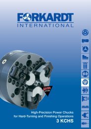
Power Chucks
270.10.07 E 10/10<br />
2<br />
This catalogue describes the key components<br />
of a power chucking system featuring the<br />
following FORKARDT power chucks:<br />
QLC, QLK,<br />
QLC/QLK-KS (KING SIZE),<br />
QLC-LS (LONG STROKE) und<br />
QLC-AG (COMPENSATING CLAMPING)<br />
QLC-KT<br />
Should you require further information<br />
beyond the data contained in this catalogue,<br />
please refer to the following FORKARDT<br />
publications for example:<br />
• Chuck Jaws<br />
• Rotating Actuating Cylinders:<br />
closed-centre hydraulic cylinders OKRJ<br />
open-centre hydraulic cylinders OKHJ<br />
• Controllers<br />
• Gripping Force Meters SKM 1200 / 1500<br />
For more information visit:<br />
www.forkardt.com<br />
As we are constantly striving to improve our products, the<br />
dimensions and specifications in this catalogue cannot always<br />
represent the latest state of the art;they are therefore given as<br />
an indication only and are not binding.<br />
Contents<br />
FORKARDT QLC/QLK Page<br />
Power Chucks<br />
Power Chucks 3<br />
Technical Features<br />
Advantages at a glance<br />
Dimensions / Performance Data<br />
QLC, QLK Power Chucks 4<br />
3QLC/K-KS Power Chucks 6<br />
(KING SIZE - large through bore)<br />
2/3QLC-LS Power Chucks 8<br />
(LONG STROKE)<br />
3QLC-AG Power Chucks 10<br />
(for compensating and self-centering<br />
clamping, gripping with pull down effect)<br />
3QLC-KT Power Chucks 12<br />
Mounting Flanges, Adaptor Flanges,<br />
Adaptor Plates<br />
for the mounting of the chucks<br />
on the machine spindle 16<br />
Chuck Jaws<br />
Quick change jaw system V-Change 17 - 18<br />
T-sliding block<br />
Jaw holder system NSTK 19 - 22<br />
HB Hard top jaw 23 - 24<br />
WBL/WBS Soft top jaw 25<br />
Some other FORKARDT products 26<br />
W O R K H O L D I N G S O L U T I O N S W O R L D W I D E
QLC, QLK, QLC/K-KS, QLC-LS, QLC-AG<br />
und QLC-KT Power Chucks<br />
Power Chuck range with Wedge Hook, Lubrication System and<br />
Centrifugal Force Compensation<br />
The new range of Power Chucks QLC, QLK,<br />
QLC/QLK-KS, QLC-LS, QLC-AG and QLC-KT marks<br />
a considerable advance in chucking technology.<br />
(A feat so often achieved by FORKARDT that it is<br />
becoming a tradition!) The QLC family of chucks is an<br />
enviable combination of proven mechanisms, innovative<br />
design, highest quality materials and advanced<br />
manufacturing techniques. Needless to say, all developed<br />
and produced in accordance with the requirements<br />
of ISO 9001 - 2000.<br />
QLC/QLK Power Chucks utilize the wedge hook<br />
system with a large through hole bore. Centrifugal<br />
force compensation is also provided together with an<br />
integrated lubricant reserve. QLC/QLK Power Chucks<br />
are universal chucks which can be<br />
used in practically all turning<br />
applications.<br />
Technical features:<br />
PPATT E NN T EE DD<br />
• Best possible clamping forces obtained through<br />
patented multiple jaw guides<br />
• Backlash free wedge hook mechanism for maximum<br />
clamping forces and highest repeatability<br />
• Base jaw profile providing exceptionally long<br />
support for greater stability and precision during<br />
internal and external clamping<br />
• Nitrided chuck body for long<br />
service life<br />
• Improved sealing of protective<br />
sleeve<br />
• Minimal loss of lubricating grease<br />
through undercuts<br />
• Integrated lubricant reservoir<br />
with improved circulation<br />
• QLC variants have centrifugal<br />
force compensation for high<br />
gripping forces at high speeds, accuracy, reliability<br />
and safety<br />
• Carefully selected matching materials – all loaded,<br />
sliding surfaces are hardened and ground<br />
• Simplified construction of the guiding piston<br />
in the chuck, with no back protrusion of the piston<br />
connection when on clamping<br />
• Axial Stroke limitation is integrated into the design<br />
of the chucks thus ensuring any over stroke of the<br />
cylinder is not problematic<br />
• Optional quick change jaws<br />
Advantages at a glance:<br />
• 30 – 40% lighter that comparable chucks<br />
• Reduced machine wear<br />
• Long maintenance intervals, high productivity<br />
• KING SIZE variants have 40% greater through hole<br />
than comparable chucks<br />
• LONG STROKE chucks are capable of clamping<br />
workpieces with great variances in diameter due to<br />
95% more clamping stroke<br />
• Sensitive, free of gripping deformation of thin<br />
walled parts<br />
• Long, reliable and accurate service life<br />
• 5 years warranty - optionally available<br />
(please complete the guarantee card and<br />
return to FORKARDT)<br />
Please contact us!<br />
W O R K H O L D I N G S O L U T I O N S W O R L D W I D E<br />
270.10.07 E 10/10<br />
3
270.10.07 E 10/10<br />
4<br />
3 QLC/K<br />
Power Chucks<br />
Technical Features:<br />
• Multiple base jaw profile with improved guiding<br />
length for greater stability and precision during<br />
internal and external clamping<br />
• Minimal loss of lubricating grease through<br />
undercuts<br />
• Best possible clamping forces are obtained<br />
through multiple jaw guides<br />
• Improved lubrication with additional, integrated<br />
lubricant reservoir and improved forced circulation<br />
• Patented backlash free wedge hook mechanism<br />
3QLC/K<br />
G2<br />
Q<br />
Q1<br />
ø A<br />
ø E<br />
for maximum clamping forces and highest<br />
repeatability<br />
• Centrifugal force compensation for highest speeds<br />
(QLC version)<br />
• Selected matching highest quality materials –all<br />
loaded, sliding surfaces are hardened and ground<br />
• Simplified construction of the guiding piston<br />
in the chuck<br />
• MIR / VC quick change jaw system optional<br />
K1 J1<br />
W O R K H O L D I N G S O L U T I O N S W O R L D W I D E<br />
ø L<br />
ø F<br />
G1<br />
G<br />
C<br />
ø B2<br />
6<br />
J<br />
K<br />
H1<br />
R<br />
H<br />
D<br />
J2<br />
P5<br />
P4<br />
ø B<br />
T<br />
O<br />
T1<br />
P1<br />
P3<br />
M<br />
ø L1<br />
max P2<br />
P6<br />
Nmax<br />
.
Dimensions / Performance data 3 QLC/K<br />
Type 3QLC, 3QLK<br />
Dimensions<br />
110-26*<br />
(QLK only)<br />
140-35*<br />
(QLK_only)<br />
160-38 200-54<br />
Chuck Size<br />
250-72 315-88<br />
Z8<br />
315-88<br />
Z11<br />
400-126<br />
Z11-S12<br />
400-126<br />
Z15-S12<br />
400-126<br />
Z11-S23<br />
400-126<br />
Z15-S23<br />
Outer diameter øA mm 110 140 162 210 257 320 320 400 400 400 400<br />
Bore øB +0.1 mm 26 35 38 54 72 88 88 126 126 126 126<br />
Chuck mounting øC mm Z4 120 Z5 Z6 Z8 Z8 Z11 Z11 Z15 Z11 Z15<br />
Jaw mounting/DIN6353 D S8 S9 S11 S11 S12 S12 S12 S12 S12 S23 S23<br />
Register ø of draw tube B2 H7 mm 32 39 42 65 77 93 93 134 134 134 134<br />
Mounting recess E H6 mm 100 120 140 170 220 220 300 300 380 300 380<br />
Actuator-ø F mm 45 48 52 76 90 110 110 150 150 150 150<br />
Mounting bolts QLC G - - M10 x 95 M12 x 90 M16 x 100 M16 x 100 M20 x 80 M20 x 130 M24 x 110 M20 x 130 M24 x 110<br />
Mounting bolts QLK G M10 x 80 M10 x 90 M10 x 95 M12 x 90 M16 x 100 M16 x 100 M20 x 80 M20 x 130 M24 x110 M20 x 130 M24 x 110<br />
Thread mounting QLC G1 - - M45 x 2 M68 x 2 M82 x 2 M100 x 2 M100 x 2 M140 x 2 M140 x 2 M140 x 2 M140 x 2<br />
Thread mounting QLK G1 M36 x1.5 M42 x1.5 M45 x 2 M68 x 2 M82 x 2 M100 x 2 M100 x 2 M140 x 2 M140 x 2 M140 x 2 M140 x 2<br />
Puller thread protective sleeve G2 M4 M4 M4 M5 M6 M6 M6 M6 M6 M6 M6<br />
Chuck width H mm 80 86 90 90 98 98 98 128 128 128 128<br />
Chuck width H1 mm 82 88 92 92 100 100 100 130 130 130 130<br />
Thread length<br />
of mounting bolts<br />
J mm 13 18 19 20 19 21 25 24 25 24 25<br />
Thread length of actuator J1 mm 19 23 18 18 24 24 24 26 26 26 26<br />
Base jaw protr. over chuck face J2 mm 6 6 5 5 6 6 6 8 8 8 8<br />
Actuator stroke K mm 12 13 17 20 20 20 20 30 30 30 30<br />
Actuator position K1 mm 12 13 17 20 20 20 20 30 30 30 30<br />
Pitch circle - ø<br />
L ±0.2 Mounting bolts<br />
mm 82.6 104.8 104.8 133.4 171.4 171.4 235 235 330 235 330<br />
Pitchcircle ø of protective sleeve L1 ±0.2 mm 58.3 74 88 88 110 130 130 173 173 173 173<br />
Jaw stroke M mm 3.2 3.5 4.5 5.4 5.4 5.4 5.4 8 8 8 8<br />
Position of master jaw Nmax. mm 22.5 28 33 44.5 56.5 61 61 85 85 85 85<br />
Jaw mounting bolts O M8 M10 M12 M12 M16 M16 M16 M16 M16 M20 M20<br />
Distance P1min. mm 4 5 6 6 8 8 8 12 12 15 15<br />
Jaw mounting bolts P10 mm 13 15 17.5/14.5 27.5 34 58 58 70.5 70.5 60 60<br />
Distance P2min. mm 18 25 25/28 25 32 32 32 37 37 46 46<br />
Jaw mounting bolts P2max. mm 27 34 36.5/36.5 46.5 58 82 82 95.5 95.5 91 91<br />
Minimum distance P3 mm 14 20 19/22 19 25 25 25 25 25 31 31<br />
Minimum distance P4 mm 6.5 9.5 10 10 10 10 10 10 10 15 15<br />
Distance T-nut and serration P5 mm 2 2.5 2.5 2.5 2.5 2.5 2.5 2.5 2.5 3.5 3.5<br />
Distance T-nut and serration P6 mm 32.5 42 48 60.5 72 99 99 115 115 115 115<br />
Jaw width Q mm 25 30 35 35 45 45 45 60 60 60 60<br />
Slot width imperial Q1H7 mm 10 12 17 17 21 21 21 21 21 25.5 25.5<br />
Slot width metric Q1H7 mm 10 12 12 14 16 21 21 21 21 21 21<br />
Width R mm 7.5 7.6 6.6 6 10 10 10 13 13 13 13<br />
Pitch of serration/imperial QLC T - - 1/16 x 90° 1/16 x 90° 1/16 x 90° 1/16 x 90° 1/16 x 90° 1/16 x 90° 1/16 x 90° 3/32° x 90° 3/32° x 90°<br />
Pitch of serration/imperial QLK T 1/16 x 90° 1/16 x 90° 1/16 x 90° 1/16 x 90° 1/16 x 90° 1/16 x 90° 1/16 x 90° 1/16 x 90° 1/16 x 90° 3/32° x 90° 3/32° x 90°<br />
Jaw mounting metric D MS10 MS12 MS12 MS14 MS16 MS21 MS21 MS21 MS21<br />
Pitch of serration/metric QLC T - - 1.5 x 60° 1.5 x 60° 1.5 x 60° 1.5 x 60° 1.5 x 60° 1.5 x 60° 1.5 x 60°<br />
Pitch of serration/metric QLK T 1.5 x 60° 1.5 x 60° 1.5 x 60° 1.5 x 60° 1.5 x 60° 1.5 x 60° 1.5 x 60° 1.5 x 60° 1.5 x 60°<br />
Distance from 1st serration<br />
Performance data<br />
T1 mm 1.5 1.5 1.5 1.5 1.5 1.5 1.5 1.5 1.5 2.5 2.5<br />
Max. actuating force Fmax. daN 2000 2500 2500 4000 6000 6000 6000 6000 6000 9000 9000<br />
Max. gripping force Fspmax. daN 4000 5500 6000 10000 15000 16000 16000 14000 14000 23000 23000<br />
Max. speed QLC n max. 1/min. - - 8000 6300 4500 4000 4000 3200 3200 3200 3200<br />
Max. speed QLK n max. 1/min. 8000 7500 6300 5000 4000 3500 3500 2500 2500 2500 2500<br />
Max. Gewicht Aufsatzbacke ** kg/Stck. 0.13 0.23 0.4 0.5 1.12 1.12 1.12 2.52 2.52 2.52 2.52<br />
Max. Ausladung Aufsatzbacke ** mm 30 30 40 45 55 55 55 70 70 70 70<br />
Weight G kg 5 8.5 11.5 18 26 38 38 90 90 90 90<br />
Moment of inertia QLC J kgm 2 - - 0.055 0.2 0.65 0.65 0.65 2.1 2.1 2.1 2.1<br />
Moment of inertia QLK J kgm 2 Ident – Number<br />
0.0075 0.02 0.04 0.095 0.2 0.65 0.65 2.1 2.1 2.1 2.1<br />
Imperial serration QLC D172000000 D172001000 D172002000 D172004000 D172005000 D172006000 D172007000 D172008000 D172009000 D172010000 D172011000<br />
Metric serration QLC D172012000 D172013000 D172014000 D172016000 D172017000 D172018000 D172019000 D172020000 D172021000<br />
Imperial serration QLK D172036000 D172037000 D172038000 D172040000 D172041000 D172042000 D172043000 D172044000 D172045000 D172046000 D172047000<br />
Metric serration QLK D172048000 D172049000 D172050000 D172052000 D172053000 D172054000 D172055000 D172056000 D172057000<br />
KDIN QLC D172024000 D172025000 D172026000 D172028000 D172029000 D172030000 D172031000 D172032000 D172033000<br />
KDIN QLK D172060000 D172061000 D172062000 D172064000 D172065000 D172066000 D172067000 D172068000 D172069000<br />
**) Limit value for max. speed<br />
W O R K H O L D I N G S O L U T I O N S W O R L D W I D E<br />
270.10.07 E 10/10<br />
5
270.10.07 E 10/10<br />
6<br />
3 QLC/K - KS<br />
Power Chucks<br />
Technical Features:<br />
• Larger through hole bore for handling larger<br />
diameter work pieces<br />
• Multiple base jaw profile with improved guiding length<br />
for greater stability<br />
• Minimal loss of lubricating grease through undercuts<br />
• Best possible clamping forces are obtained through<br />
patented multiple jaw guides<br />
• Improved lubrication with additional, integrated lubricant<br />
and improved forced circulation<br />
• Patented backlash free wedge hook mechanism for<br />
3QLC-KS<br />
3QLK-KS<br />
L1<br />
L1<br />
Q<br />
Q1<br />
Q<br />
Q1<br />
G2<br />
G2<br />
øA<br />
øA<br />
øE<br />
øE<br />
øL<br />
øF<br />
øL<br />
øF<br />
G1<br />
G1<br />
maximum clamping forces and highest repeatability<br />
• Centrifugal force compensation for highest speeds<br />
• Selected matching highest quality materials – all loaded,<br />
sliding surfaces are hardened and ground<br />
• Simplified construction of the guiding piston<br />
in the chuck<br />
• Axial Stroke limitation is integrated into the design<br />
of the chucks thus ensuring any over stroke<br />
of the cylinder is not problematic<br />
• MIR / VC quick change jaw system optional<br />
øB<br />
øB1<br />
øL1<br />
W O R K H O L D I N G S O L U T I O N S W O R L D W I D E<br />
G<br />
G<br />
C<br />
øB2<br />
J<br />
C<br />
øB2<br />
J<br />
6<br />
6<br />
R<br />
K1 J1<br />
R<br />
K<br />
H1<br />
H<br />
K1 J1<br />
K<br />
H1<br />
H<br />
P4<br />
P5<br />
P4<br />
P5<br />
T1<br />
J2<br />
T1<br />
D<br />
øB<br />
øB1<br />
øL1<br />
J2<br />
O<br />
P1<br />
T M<br />
D<br />
O<br />
P1<br />
T M<br />
P3<br />
Nmax<br />
P3<br />
Nmax<br />
P2<br />
P2<br />
P6<br />
P6
Dimensions / Performance data 3 QLC/K - KS<br />
Chuck Size<br />
Type 3QLC-KS / QLK-KS<br />
D i m e n s i o n s<br />
200-77 250-101 315-135 400-168<br />
Outer diameter øA mm 210 257 320 400<br />
Bore øB +0.1 mm 77 101 135 168<br />
Chuck mounting øC mm Z6 Z8 Z11 Z15<br />
Jaw mounting/DIN 6353 D S11 S11 S12 S12<br />
Register Ø of draw tube B2H7 mm 85 112 140 173<br />
Mounting recess E H6 mm 170 220 300 380<br />
Actuator Ø F mm 97 123 153 190<br />
Mounting bolts G M12 x 90 M16 x 95 M20 x 90 M24 x 80<br />
Thread mounting G1 M90 x 2 M115 x 2 M145 x 2 M180 x 2<br />
Puller thread protective sleeve G2 M5 M5 M6 M6<br />
Chuck width H mm 90 90 98 98<br />
Chuck width H1 mm 92 92 100 100<br />
Thread length of mounting bolts J mm 20 22 22 30<br />
Thread length of actuator J1 mm 24 24 24 24<br />
Base jaw protrusion over chuck face J2 mm 5 5 6 6<br />
Actuator stroke K mm 18.5 20 20 20<br />
Actuator position K1 mm 18.5 20 20 20<br />
Pitch circle Ø of Mounting bolts L ±0.2 mm 133.4 171.4 235 330.2<br />
Pitch circle Ø of protective sleeve L1 ±0.2 mm 100 129 173 210<br />
Jaw stroke M mm 5 5.3 5.3 5.3<br />
Position of master jaw Nmax mm 52.5 67.5 85 100.5<br />
Jaw mounting bolts O M12 M12 M16 M16<br />
Distance P1min mm 6 6 8 8<br />
Jaw mounting bolts P1max mm 20 29 34 58<br />
Distance P2min mm 25 25 32 32<br />
Jaw mounting bolts P2max mm 39 48 58 82<br />
Minimum distance P3 mm 19 19 24 24<br />
Minimum distance P4 mm 10 10 10 10<br />
Distance T-nut and serration P5 mm 2.5 2.5 2.5 2.5<br />
Length of serrations P6 mm 52.5 61 75 99.5<br />
Jaw width Q mm 35 35 45 45<br />
Slot width imperial Q1H7 mm 17 17 21 21<br />
Slot width metric Q1H7 mm 12 14 16 21<br />
Width R mm 6.6 6.6 9.6 9.6<br />
Pitch of serration / imperial T 1/16” x 90° 1/16” x 90° 1/16” x 90° 1/16” x 90°<br />
Jaw mounting metric D MS12 MS14 MS16 MS21<br />
Pitch of serration metric T 1.5 x 60° 1.5 x 60° 1.5 x 60° 1.5 x 60°<br />
Distance from 1st serration<br />
P e r f o r m a n c e d a t a<br />
T1 mm 1.5 1.5 1.5 1.5<br />
Max. actuating force Fmax daN 2,500 4,000 6,000 6,000<br />
Max. gripping force Fspmax daN 6,000 10,000 15,000 16,000<br />
Max. speed QLC-KS nmax 1/min 6,300 5,000 4,000 3,200<br />
Max. speed QLK-KS nmax 1/min 5,000 4,200 3,000 2,800<br />
Weight G kg 16 26 37 63<br />
Moment of inertia QLC-KS kgm 2 0.076 0.18 0.4 1.04<br />
Moment of inertia QLK-KS kgm 2 I d e n t – N u m b e r<br />
0.076 0.175 0.4 1.04<br />
Imperial serration QLC-KS D170130000 D172073000 D168480000 D168481000<br />
Metric serration QLC-KS D168718000 D168719000 D168720000 D168721000<br />
Imperial serration QLK-KS D170131000 D168576000 D168577000 D168578000<br />
Metric serration QLK-KS D170132000 D168538000 D168539000 D168540000<br />
W O R K H O L D I N G S O L U T I O N S W O R L D W I D E<br />
270.10.07 E 10/10<br />
7
270.10.07 E 10/10<br />
8<br />
2/3 QLC – LS<br />
Power Chucks<br />
Technical Features:<br />
• 95 % more clamping stroke for work pieces<br />
with variations in diameter<br />
• Easily grip stepped work pieces<br />
• Available as 2- and 3-jaw QLC versions<br />
(QLK variants not available)<br />
• Multiple base jaw profile with improved guiding<br />
length for greater stability<br />
2QLC-LS<br />
3QLC-LS<br />
L1<br />
G2<br />
L1<br />
Q<br />
Q1<br />
Q<br />
Q1<br />
G2<br />
øA<br />
øE<br />
øL<br />
øF<br />
G1<br />
øB2<br />
• Minimal loss of lubricating grease through<br />
undercuts<br />
• Nitrided chuck body for longer service life<br />
• Selected matching highest quality materials – all<br />
loaded, sliding surfaces are hardened and ground<br />
• Long maintenance intervals<br />
• Centrifugal force compensation for highest speeds<br />
W O R K H O L D I N G S O L U T I O N S W O R L D W I D E<br />
G<br />
øA<br />
øE<br />
øL<br />
øF<br />
G1<br />
øB2<br />
G<br />
C<br />
J<br />
C<br />
J<br />
6<br />
6<br />
K1<br />
K1<br />
R<br />
J1<br />
R<br />
K<br />
J1<br />
K<br />
H1<br />
H<br />
H1<br />
H<br />
P4<br />
P5<br />
P4<br />
P5<br />
T1<br />
øB<br />
J2<br />
T1<br />
øB<br />
J2<br />
D<br />
T<br />
O<br />
P1<br />
P3<br />
øL1<br />
M<br />
Nmax<br />
D<br />
T<br />
O<br />
P1<br />
P3<br />
øL1<br />
M<br />
Nmax<br />
P2<br />
P2<br />
P6<br />
P6
Dimensions / Performance data 2/3 QLC - LS<br />
Chuck Size<br />
Typ 2QLC-LS / 3QLC-LS<br />
D i m e n s i o n s<br />
160-30 200-41 250-52 315-71<br />
Outer diameter øA mm 162 210 257 320<br />
Bore øB +0.1 mm 30 41 52 71<br />
Chuck mounting øC mm Z5 Z6 Z8 Z11<br />
Jaw mounting/DIN 6353 D S11 S11 S12 S12<br />
Register Ø of draw tube B2H7 mm 42 65 77 93<br />
Mounting recess EH6 mm 140 170 220 300<br />
Actuator Ø F mm 52 76 91 110<br />
Mounting bolts G M10 x 95 M12 x 100 M16 x 110 M20 x 90<br />
Thread mounting G1 M45 x 2 M68 x 2 M82 x 2 M100 x 2<br />
Puller thread protective sleeve G2 M4 M5 M6 M6<br />
Chuck width H mm 93 96 110 120<br />
Chuck width H1 mm 95 98 112 122<br />
Thread length of mounting bolts J mm 15.7 19 20 25<br />
Thread length of actuator J1 mm 23.4 24 24 24<br />
Base jaw protrusion over chuck face J2 mm 5 5 6 6<br />
Actuator stroke K mm 20 23 27 32<br />
Actuator position K1 mm 20 23 27 32<br />
Pitch circle Ø of Mounting bolts L ±0.2 mm 104.8 133.4 171.4 235<br />
Pitch circle Ø of protective sleeve L1 ±0.2 mm 88 96 120 140<br />
Jaw stroke M mm 8 9.3 10.9 12.9<br />
Position of master jaw Nmax mm 36 43.7 52.9 70.5<br />
Jaw mounting bolts O M12 M12 M16 M16<br />
Distance P1min mm 6 6 8 8<br />
Jaw mounting bolts P1max mm 14 35 40 58<br />
Distance P2min mm 25 25 32 32<br />
Jaw mounting bolts P2max mm 33 49 58 82<br />
Minimum distance P3 mm 19 19 24 24<br />
Minimum distance P4 mm 10 10 10 10<br />
Distance T-nut and serration P5 mm 2.5 2.5 2.5 2.5<br />
Length of serrations P6 mm 45 61 75.5 89<br />
Jaw width Q mm 35 35 45 45<br />
Slot width imperial Q1H7 mm 17 17 21 21<br />
Slot width metric Q1H7 mm 12 14 16 21<br />
Width R mm 6.6 6.6 9.6 9.6<br />
Pitch of serration / imperial T 1/16" x 90° 1/16" x 90° 1/16" x 90° 1/16" x 90°<br />
Jaw mounting metric D MS12 MS14 MS16 MS21<br />
Pitch of serration metric T 1.5 x 60° 1.5 x 60° 1.5 x 60° 1.5 x 60°<br />
Distance from 1st serration<br />
P e r f o r m a n c e d a t a<br />
T1 mm 1.5 1.5 1.5 1.5<br />
Max. actuating force 2QLC-LS Fmax daN 2,400 3,700 4,600 5,700<br />
Max. gripping force 2QLC-LS Fspmax daN 3,700 6,000 7,500 10,000<br />
Max. actuating force 3QLC-LS Fmax daN 3,500 5,500 7,000 8,500<br />
Max. gripping force 3QLC-LS Fspmax daN 5,500 9,000 11,000 15,000<br />
Max. speed nmax 1/min 6,000 5,500 4,000 3,200<br />
Weight G kg 9 18 31 50<br />
Moment of inertia kgm 2 I d e n t – N u m b e r<br />
0.028 0.09 0.25 0.6<br />
Imperial serration 2QLC-LS D169619000 D169621000 D169622000 D169623000<br />
Metric serration 2QLC-LS D169817000 D169818000 D169819000 D169820000<br />
Imperial serration 3QLC-LS D169563000 D169565000 D169566000 D169567000<br />
Metric serration serration3QLC-LS 3QLC-LS D169813000 D169813000 D169814000 D169814000 D169815000 D169815000 D169816000 D169816000<br />
**) Limit value for max. speed ** Pitch of serration metric * Pitch of serration / imperial<br />
270.10.07 E 10/10<br />
9
270.10.07 E 10/10<br />
10<br />
3 QLC – AG<br />
Power Chucks<br />
Technical Features:<br />
• Compensating chuck to clamp off-center parts<br />
with high precision<br />
• Easy moving compensation even at high<br />
clamping forces<br />
• Ingenious pull-back action for improved<br />
part location on center<br />
• Easily interchangeable and finely adjustable<br />
center housings<br />
• Simple change-over for self-centering mode<br />
for general chucking work<br />
• Centrifugal force compensation for highest<br />
speeds (QLK variants not available)<br />
• Axial stroke limitation is integrated,<br />
ensuring any over stroke of the cylinder<br />
is not problematic<br />
3QLC-AG<br />
Q<br />
Q1<br />
øA<br />
øE<br />
øF<br />
øL<br />
W O R K H O L D I N G S O L U T I O N S W O R L D W I D E<br />
G1<br />
J1 K1<br />
G<br />
C<br />
6<br />
J<br />
M1<br />
K<br />
H3<br />
H1 P4<br />
P5<br />
H<br />
H2<br />
O<br />
T1<br />
P3 P1<br />
T<br />
P2<br />
P6<br />
M<br />
Nmax
Dimensions / Performance data 3 QLC - AG<br />
Type 3QLC-AG<br />
D i m e n s i o n s<br />
Chuck Size<br />
200 250 315<br />
Outer diameter øA mm 210 257 315<br />
Bore øB mm 0 0 0<br />
Chuck mounting øC mm Z6 Z8 Z8<br />
Jaw mounting D S11 S12 S12<br />
Mounting recess E mm 170 220 220<br />
Actuator Ø F mm 44 50 50<br />
Mounting bolts G 3 x M12 3 x M16 3 x M16<br />
Thread mounting G1 M20 M24 M24<br />
Chuck width H mm 106 113 113<br />
Chuck back to serration H1 mm 108 115 115<br />
Point height H2 mm 18 22 22<br />
Pull-back stroke H3 mm 0.2 0.2 0.2<br />
Thread length of mounting bolts J mm 18 24 24<br />
Thread length of actuator J1 mm 40 45 45<br />
Actuator stroke K mm 20 20 20<br />
Actuator position K1 mm 45 55 55<br />
Pitch circle Ø Mounting bolts L mm 133.4 171.4 171.4<br />
Jaw stroke M mm 5.3 5.3 5.3<br />
Compensating stroke M1 mm 2 2 2<br />
Position of master jaw Nmax mm 42.9 53.5 55.5<br />
Jaw mounting bolts O M12 M16 M16<br />
Distance P1min mm 6 8 8<br />
Jaw mounting bolts P1max mm 34 41 65<br />
Distance P2min mm 25 32 32<br />
Jaw mounting bolts P2max mm 53 65 89<br />
Minimum distance P3 mm 19 24 24<br />
Minimum distance P4 mm 10 10 10<br />
Distance T-nut and serration P5 mm 2.5 2.5 2.5<br />
Length of serrations P6 mm 61 75 99.5<br />
Jaw width Q mm 35 45 45<br />
Slot width / imperial Q1 mm 17 21 21<br />
Pitch of serration / imperial<br />
P e r f o r m a n c e d a t a<br />
T 1/16" x 90° 1/16" x 90° 1/16" x 90°<br />
Max. actuating force Fmax daN 3,600 5,000 5,500<br />
Max. gripping force Fspmax daN 7,000 12,000 13,000<br />
Max. speed nmax 1/min 4,700 4,500 4,000<br />
Weight G kg 21 32 44<br />
Moment of inertia J kgm2 I d e n t – N u m b e r<br />
0.11 0.3 0.8<br />
Imperial serration D170783000 D170393000 D169907000<br />
Metric serration D170788000 D170789000 D170790000<br />
Note: QLC-AG chucks may optionally be equipped with spring loaded centres or inserts for concentric operation.<br />
**) Limit value for max. speed<br />
W O R K H O L D I N G S O L U T I O N S W O R L D W I D E<br />
270.10.07 E 10/10<br />
11
V1 B-B<br />
270.10.07 E 10/10<br />
12<br />
3 QLC – KT<br />
Power Chucks<br />
PPoowweerr cchhuucckk ffoorr hhiigghheesstt ssttaannddaarrddss<br />
In order to fulfil highest requirements the wellestablished<br />
QLC power chuck was altered towards a<br />
solid version without bore.<br />
The combination of the patented base jaw guiding<br />
shape of the QLC chucks with the rigidity of KT<br />
chucks provided chuck characteristics perfectly<br />
suitable for heavy cutting applications.<br />
The QLC-KT chucks are determined to be used with<br />
high clamping forces plus extraordinary accuracy.<br />
Example:<br />
3 QLC-KT 400 Performance data<br />
Max. = 26 000 daN<br />
gripping force<br />
Max. rpm = 3200 1/min<br />
3QLC-KT<br />
B<br />
B<br />
A<br />
A<br />
Q1<br />
Q<br />
øA<br />
C/øE<br />
øL<br />
øF<br />
G1<br />
Technical Features:<br />
• Maximum Gripping force<br />
• Maximum Speed<br />
• Quick jaw change<br />
• MIR, VC quick change jaw system<br />
optional<br />
W O R K H O L D I N G S O L U T I O N S W O R L D W I D E<br />
J1<br />
G<br />
6<br />
K1<br />
K<br />
J H<br />
A-A<br />
H1<br />
Chuck mounting Z<br />
G2<br />
P4<br />
O<br />
P1<br />
T1<br />
P3<br />
P2<br />
P6<br />
N<br />
L1
Dimensions / Performance data 3 QLC- KT<br />
Abbreviation explanation for chuck mountings<br />
Cylindrical recess DIN 6353<br />
FORKARDT DIN Mounting recess Pitch circle<br />
Type designation Size H6<br />
Z5 5 ø 140 Ø 104.8 with M10<br />
Z6 6 ø 170 Ø 133.4 with M12<br />
Z8 8 ø 220 Ø 171.4 with M16<br />
Z11 11 ø 300 Ø 235.0 with M20<br />
Z15 15 ø 380 Ø 330.2 with M24<br />
Short taper - direct recess DIN 55026 shape A<br />
FORKARDT DIN Taper-Ø Pitch circle<br />
Type designation Size d2<br />
K5 5 82.573 Ø 104.8 with M10<br />
K6 6 106.385 Ø 133.4 with M12<br />
K8 8 139.731 Ø 171.4 with M16<br />
K11 11 196.883 Ø 235.0 with M20<br />
K15 15 283.791 Ø 330.2 with M24<br />
Short taper - bayonet mounting DIN 55027<br />
FORKARDT DIN Taper-Ø Pitch circle<br />
Type designation Size d2<br />
J5 5 82.573 Ø 104.8 with M10<br />
J6 6 106.385 Ø 133.4 with M12<br />
J8 8 139.731 Ø 171.4 with M16<br />
J11 11 196.883 Ø 235.0 with M20<br />
J15 15 283.791 Ø 330.2 with M24<br />
Ident-Numbers and connecting dimensions - Performance data<br />
Chuck type Ident-No. and mounting dimensions Dimensions<br />
Chuck mounting<br />
Pitch of serration<br />
Cross tenon<br />
Quick change jaw system VC<br />
mm mm mm daN daN min -1<br />
3QLC-KT 160 Z5 S11 D174005000 D174007000 D174008000 184 40 M16 114 3,000 7,000 7,000<br />
3QLC-KT 160 K5 S11 D174010000 D174012000 D174013000 184 40 M16 114 3,000 7,000 7,000<br />
3QLC-KT 200 Z6 S11 D174025000 D174027000 D174005000 200 40 M20 124 5,000 11,500 6,000<br />
3QLC-KT 200 K6 S11 D174030000 D174032000 D174005000 200 40 M20 124 5,000 11,500 6,000<br />
3QLC-KT 250 Z8 S11 D174045000 D174047000 D174005000 250 50 M24 142 7,500 16,000 5,000<br />
3QLC-KT 250 Z8 S11 D174050000 D174052000 D174005000 250 50 M24 152 7,500 16,000 5,000<br />
3QLC-KT 315 Z8 S11 D174065000 D174067000 D174005000 315 50 M24 142 8,000 17,000 4,000<br />
3QLC-KT 315 K8 S11 D174070000 D174072000 D174005000 315 50 M24 8,000 17,000 4,000<br />
3QLC-KT 315 Z11 S11 D174832000 D174834000 D174005000 315 50 M24 142 8,000 17,000 4,000<br />
3QLC-KT 400 Z11 S12 D174840000 400 60 M30 181 7,300 16,000 3,200<br />
3QLC-KT 400 Z15 S12 D174836000 400 60 M30 181 7,300 16,000 3,200<br />
3QLC-KT 400 Z11 S23 D174085000 D174087000 D174088000 400 60 M30 181 12,000 26,000 3,200<br />
3QLC-KT 400 K11 S23 D174090000 D174092000 D174093000 400 60 M30 12,000 26,000 3,200<br />
3QLC-KT 400 Z15 S23 D174841000 D174838000 D174839000 400 60 M30 181 12,000 26,000 3,200<br />
W O R K H O L D I N G S O L U T I O N S W O R L D W I D E<br />
Outer diameter A<br />
Jaw width Q<br />
Mounting thread G1<br />
Chuck width H<br />
Max. actuating force Fmax<br />
Max. Clamping force FSPmax<br />
Max. speed nmax<br />
270.10.07 E 10/10<br />
13
V1 B-B<br />
270.10.07 E 10/10<br />
14<br />
B<br />
3QLC-KT with jaw mounting S<br />
Type 3QLC-KT<br />
Dimensions<br />
160 200 250 250<br />
Chuck Size<br />
315 315 400 400 400<br />
Outer diameter A mm 184 200 250 250 315 315 400 400 400<br />
Bore B mm - - - - - - - - -<br />
Chuck mounting C Z5 Z6 Z8 K8 Z8 Z11 Z11 Z11 Z15<br />
Jaw mounting D1) S11 S11 S12 S12 S12 S12 S12 S23 S23<br />
T1) (1/16"x 90°) (1/16"x 90°) (1/16"x 90°) (1/16"x 90°) (1/16"x 90°) (1/16"x 90°) (1/16"x 90°) (3/32"x 90°) (3/32"x 90°)<br />
Mounting recess E mm 140H6 170H6 220 139.731 220H6 300H6 300H6 300H6 380H6 Actuator F mm 34 50 52 52 52 52 68 68 68<br />
Mounting bolts G M10 (3x) M12 (3x) M16 (3x) M16 (3x) M16 (3x) M20 (3x) M20 (3x) M20 (3x) M24 (3x)<br />
Thread mounting G1 M16 M20 M24 M24 M24 M24 M30 M30 M30<br />
Thread mounting G2 M6 M6 M6 M6 M6 M6 M10 M10 M10<br />
Chuck width H mm 114 124 142 152 142 142 177 177 177<br />
H11) mm 120 130 150 160 150 150 185 185 185<br />
Thread length J mm 15 18 24 24 24 30 30 30 30<br />
Thread length of actuator J1 mm 40 45 56 56 56 56 55 55 55<br />
Actuator stroke K mm 20 20 26 26 26 26 32 32 32<br />
Actuator position K1 mm 25 30 30 30 30 30 30 30 30<br />
Pitch circle-Ø L mm 104.8 133.4 171.4 171.4 171.4 235 235 235 330.2<br />
Mounting bolts L1 mm 60 70 105 105 105 235 235 235 330.2<br />
Jaw stroke M mm 5.3 6.5 8 8 8 8 10 10 10<br />
Position of master jaw N1) mm 31.7 40.1 48 48 48 48 70 70 70<br />
Jaw mounting bolts O 1) M12 M12 M16 M16 M16 M16 M16 M20 M20<br />
Distance min. P11) Jaw mounting bolt<br />
mm 10 10 12 12 12 12 12 14 14<br />
Distance max. P21) Jaw mounting bolt<br />
mm 50.2 50.3 55.5 55.5 96 96 118 115 115<br />
Minimum distance P3 1) mm 19 19 25 25 25 25 25 31 31<br />
Minimum distance P4 1) mm 9 9 10 10 10 10 10 14 14<br />
Length of serrations P6 mm 60.3 59.9 77 77 109.5 109.5 130 130 130<br />
Jaw width Q mm 40 40 50 50 50 50 50 60 60<br />
Slot width Q11) mm 17 H7 17H7 21H7 21H7 21H7 21H7 21H7 25.5H7 25.5H7 Distance from 1st serration T1 1) mm 1.5 1.5 1.5 1.5 1.5 1.5 1.5 2.5 2.5<br />
T-slot width<br />
Performance data<br />
V1 mm 14 14 18 18 18 18 22 22 22<br />
Max. actuating force FAX1) daN 3,000 5,500 7,500 7,500 8,000 8,000 7,300 12,000 12,000<br />
Max. speed n n min -1 7,000 6,000 5,000 5,000 4,000 4,000 3,200 3,200 3,200<br />
Max. gripping force FSP 1) daN 7,000 11,500 16,000 16,000 17,000 17,000 16,000 26,000 26,000<br />
Weight G kg 21 27 51 51 81 81 163 163 163<br />
1) valid only for jaw mounting S<br />
B<br />
A<br />
A<br />
Q1<br />
Q<br />
øA<br />
C/øE<br />
øL<br />
øF<br />
G1<br />
J1<br />
G<br />
6<br />
K1<br />
K<br />
J H<br />
A-A<br />
H1<br />
Chuck mounting Z<br />
G2<br />
P4<br />
O<br />
P1<br />
T1<br />
P3<br />
P2<br />
P6<br />
N<br />
L1<br />
C/øE<br />
7°7'30"<br />
short taper<br />
DIN 55028<br />
G<br />
K1<br />
J<br />
H1<br />
H<br />
Chuck mounting K, J<br />
W O R K H O L D I N G S O L U T I O N S W O R L D W I D E
3QLC-KT with jaw mounting KDIN<br />
Type 3QLC-KT<br />
Dimensions<br />
Chuck Size<br />
200 250 315 400<br />
Chuck mounting C mm Z6 Z8 Z8 / Z11 Z11 / Z15<br />
Jaw mounting D KDIN KDIN KDIN K 25<br />
Chuck width H12) mm 130 150 150 185<br />
Jaw position N2) mm 70 88 100 13.5<br />
Jaw mounting bolt O 2) M12 M16 M16 M20<br />
Distance jaw mounting bolt P1 2) mm 30 40 50 70<br />
Minimum distance P4 2) mm 9 12 10 20<br />
Slot width Q12) mm 16 H7 20H7 20H7 25H7 Feather key width Q22) Performance data<br />
mm 12 g6 16g6 16g6 25g6<br />
Max. actuating force FAX2) daN 5,500 7,500 8,000 12,000<br />
Max. gripping force FSP2) daN 11,500 16,000 17,000 26,000<br />
Max. speed nmax 1/min 6,000 5,000 4,000 3,200<br />
2) valid only for jaw mounting KDIN – other dimensions see jaw mounting S<br />
Q1<br />
Q2<br />
G<br />
K1<br />
J<br />
Chuck mounting Z<br />
3QLC-KT with jaw mounting VC<br />
G<br />
K1<br />
J<br />
H1<br />
H1<br />
Chuck mounting Z<br />
P4<br />
D<br />
D<br />
N<br />
O<br />
O1<br />
O1<br />
N<br />
Short taper<br />
DIN 55028<br />
G<br />
Short taper<br />
DIN 55028<br />
G<br />
K1<br />
J<br />
K1<br />
J<br />
H1<br />
Chuck mounting K, J<br />
Type 3QLC-KT<br />
Dimensions<br />
Chuck Size<br />
160 200 250 315 400<br />
Chuck mounting C mm Z5 Z6 Z8 Z8 / Z11 Z11 / Z15<br />
Jaw mounting D VC11 VC21 VC22 VC22 VC31<br />
Chuck width H13) mm 130.5 143 163 163 206<br />
Jaw position N3) Performance data<br />
mm 55.9 70 86.5 103 135<br />
Max. actuating force FAX3) daN 3,000 5,500 7,500 8,000 12,000<br />
Max. gripping force FSP3) daN 7,000 11,500 16,000 17,000 26,000<br />
Max. speed nmax 1/min 7,000 6,000 5,000 4,000 3,200<br />
3) valid only for jaw mounting VC – other dimensions see jaw mounting S<br />
H1<br />
Chuck mounting K, J<br />
W O R K H O L D I N G S O L U T I O N S W O R L D W I D E<br />
270.10.07 E 10/10<br />
15
270.10.07 E 10/10<br />
16<br />
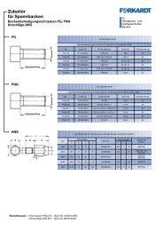
Mounting Flanges, Adaptors and Adaptor Plates:<br />
Flanges with bayonet plate attachment for mounting on spindle J noses<br />
to DIN 55022, DIN 55027, ISO 702 / III J<br />
Spindle nose Flange type Ident. No. Dimensions Studs and collar nuts<br />
Size B D L1 L2 FN Ident. No. Qty.<br />
4 FF100-J4 D1074085000 45 18 82.6 85.0 322 D1070505000 3<br />
5 FF120-J5 - 50 24 104.8 104.8 322 D1070505000 4<br />
5 FF140-J5 D1074086000 50 24 104.8 104.8 322 D1070505000 44<br />
6 FF170-J6 D1074090000 65 28 133.4 133.4 322 D1070506000 4<br />
8 FF220-J8 D1074097000 80 32 171.4 171.4 322 D1070507000 4<br />
11 FF300-J11 D1074104000 90 35 235.0 235.0 322 D1070508000 6<br />
15 FF380-J15 D1074108000 120 42 330.2 330.2 324 D1070517000 6<br />
Order code example: 1 mounting flange type FF 170-J6, Ident. No. D1074090000,<br />
1 set of studs with collar nuts size 6, Ident. No. D1070506000<br />
Flanges with camlock attachment for mounting on spindle D noses<br />
to DIN 55029, ISO 702 / II, ASA B 5.9 D1 D<br />
Spindle nose Flange type Ident. No. Dimensions Camlock studs<br />
Size B D L1 L2 FN Ident. No. Qty.<br />
4 FF100-D4 - 45 28 82.6 82.6 286 D1070511000 3<br />
5 FF120-D5 - 50 30 104.8 104.8 287 D1070512000 6<br />
5 FF140-D5 D1074119000 50 30 104.8 104.8 287 D1070512000 6<br />
6 FF170-D6 D1074123000 65 35 133.4 133.4 288 D1070513000 6<br />
8 FF220-D8 D1074130000 80 40 171.4 171.4 289 D1070514000 6<br />
11 FF300-D11 D1074137000 90 45 235.0 235.0 289 D1070515000 6<br />
15 FF380-D15 D1074141000 120 50 330.2 330.2 291 D1070516000 6<br />
Order code example: 1 mounting flange type FF 170 - D6, Ident. No. D1074123000, 1 set of camlock studs size 6, Ident. No. D1070513000<br />
Adaptor flanges including mounting bolts for spindle noses<br />
DIN 55021 A/B, DIN 55026 A/B, ISO 702/I A1/A2, ASA B5.9 A1/A2 K<br />
Spindle nose Flange type Ident. No. Dimensions Mounting bolts<br />
Size B D L1 L2 DIN 912 10.9<br />
3 ZWF100-K3 - 35 18 70.6 82.6 3 x M10 x 20<br />
4 ZWF120-K4 - 50 20 82.6 104.8 3 x M10 x 20<br />
4 ZWF140-K4 D1074053000 50 20 85.0 104.8 3 x M10 x 20<br />
4<br />
4<br />
ZWF140-K4<br />
ZWF140-K4<br />
D1074053000<br />
D1044757000<br />
50<br />
50<br />
18<br />
18<br />
104.8<br />
104.8<br />
85.0<br />
82.6<br />
3 x M10 x 20<br />
5 ZWF170-K5 D1074056000 60 24 133.4 104.8 4 x M10 x 25<br />
6 ZWF220-K6 D1074060000 80 28 171.4 133.4 4 x M12 x 30<br />
8 ZWF300-K8 D1074065000 90 32 235.0 171.4 4 x M16 x 35<br />
11 ZWF380-K11 D1074068000 120 35 330.2 235.0 6 x M20 x 40<br />
DIN 55021 Pitch circle diameter 85 mm DIN 55026 Pitch circle diameter 82.6 mm Order code example, 1 adapter flange ZWF 140 - K4,<br />
Ident. No. D1044757000<br />
Adaptor plates for spindle noses to DIN 55021 A,<br />
DIN 55026 A, ISO 702/I A2, ASA B 5.9 K A2<br />
Spindle nose Flange type Ident. No. Dimensions<br />
Size D L2 L*<br />
4 ZWS100-K4 - 12 82.6 10<br />
5 ZWS120-K5 - 14 104.8 15<br />
5 ZWS140-K5 D1074035000 14 104.8 15<br />
6 ZWS170-K6 D1074036000 15 133.4 15<br />
8 ZWS220-K8 D1074038000 17 171.4 15<br />
11 ZWS300-K11 D1074040000 19 235.0 20<br />
15 ZWS380-K15 D1074042000 21 330.2 20<br />
*The length of the chuck mounting bolts must be increased by the amount "L"<br />
when using these adapter plates!<br />
Order code example: 1 adaptor plate ZWS-K5. Ident. No. D1074035000.<br />
Note: The respective chuck type must be clearly specified when ordering flanges or adaptors separately.<br />
W O R K H O L D I N G S O L U T I O N S W O R L D W I D E<br />
D<br />
B<br />
L2<br />
L2<br />
L1<br />
Mounting Flanges J<br />
D<br />
B<br />
B<br />
L2<br />
L1<br />
Mounting Flanges D<br />
D<br />
Adaptor Flanges<br />
ZWF<br />
D<br />
Adaptor Plates<br />
ZWS<br />
L2<br />
L1<br />
L1
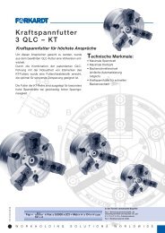
VC<br />
V-Change - Quick change<br />
Jaw system VC<br />
The quick change jaw system VC is as simple in<br />
handling as effective in reduction of the set-up time.<br />
In spite of the same repeatability and less space<br />
requirement - compared to general mounting systems<br />
- very high clamping forces are permitted as well.<br />
Therefore, this quick change jaw system in<br />
connection with a high-quality chuck represents an<br />
economic problem solution to improve productivity.<br />
Advantages at a glance:<br />
• Jaw change within seconds<br />
• For I.D. and O.D. clamping<br />
• Jaw change system easily to be realised<br />
automatically<br />
• Best repeatability<br />
PPATT EE NN TT E D<br />
W O R K H O L D I N G S O L U T I O N S W O R L D W I D E<br />
270.10.07 E 10/10<br />
17
270.10.07 E 10/10<br />
18<br />
VC<br />
Soft Top Jaws VC<br />
O.D. clamping<br />
Soft Top Jaws<br />
V-Change<br />
EEXXTTEERRNNAALL<br />
Material: Heat treatable<br />
42CrMo4<br />
I.D. clamping<br />
Soft Top Jaws<br />
V-Change<br />
IINNTTEERRNNAALL<br />
Material: Heat treatable<br />
42CrMo4<br />
ATTENTION: Treatment permissible just outside the –--– mounting!<br />
Jaw Dimensions (mm) Weight Min. clamping<br />
Chuck type type Ident No. A B C D E F G H I Kg./each diameter (mm)<br />
QLC 160 VC 11<br />
QLC KT 160 VC 11<br />
VC 11<br />
VC 11<br />
D174546000 85 40 60 46 10 35 31 17 50 1.3<br />
20<br />
25<br />
QLC 200 VC 21<br />
QLC KT 200 VC 21<br />
VC 21<br />
VC 21<br />
D174548000 105 40 60 59 10 40 38 20 50 1.6<br />
30<br />
10<br />
QLC 250 VC 22 VC 22 30<br />
QLC KT 250 VC 22<br />
QLC 315 VC 22<br />
VC 22<br />
VC 22<br />
D174550000 120 60 80 74 10 40 45 20 67.5 3.9<br />
12<br />
65<br />
QLC KT 315 VC 22 VC 22 45<br />
QLC 400 VC 31<br />
QLC KT 400 VC 31<br />
VC 31<br />
VC 31<br />
D174552000 152 60 80 90 10 54 60 22 59.5 4.4<br />
105<br />
75<br />
ATTENTION: Treatment permissible just outside the –--– mounting!<br />
Jaw Dimensions (mm) Weight Min. clamping<br />
Chuck type type Ident No. A B C D E F G H I Kg./each diameter (mm)<br />
QLC 160 VC 11<br />
QLC KT 160 VC 11<br />
VC 11<br />
VC 11<br />
D174547000 91 40 60 46 10 35 31 17 50 1.4 25<br />
QLC 200 VC 21<br />
QLC KT 200 VC 21<br />
VC 21<br />
VC 21<br />
D174549000 99 40 60 59 10 40 38 20 50 1.5<br />
45<br />
35<br />
QLC 250 VC 22 VC 22 45<br />
QLC KT 250 VC 22<br />
QLC 315 VC 22<br />
VC 22<br />
VC 22<br />
D174551000 120 60 80 74 10 40 45 20 67.5 4.0<br />
35<br />
90<br />
QLC KT 315 VC 22 VC 22 70<br />
QLC 400 VC 31<br />
QLC KT 400 VC 31<br />
VC 31<br />
VC 31<br />
D174553000 155 60 80 90 10 54 60 22 59.5 4.4<br />
150<br />
100<br />
W O R K H O L D I N G S O L U T I O N S W O R L D W I D E
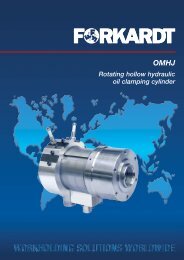
NSTK<br />
T-sliding block<br />
General<br />
As a further highlight of our jaw holder system,<br />
<strong>Forkardt</strong> offers the NSTK T-sliding block.<br />
Changing or adjusting chuck jaws to a different<br />
clamping diameter involves lengthy setting-up<br />
operations.<br />
Example:<br />
1st operation: Chuck jaws with<br />
gripping claws<br />
2nd operation: Chuck jaws with<br />
turned inside<br />
diameter<br />
The new jaw holder system consists of the<br />
NSTK T-sliding block and soft jaws for use with<br />
either SKA or SKI clamping inserts for the first<br />
operation or for turning to the required clamping<br />
diameter under clamping pressure for<br />
greater setting up efficiency.<br />
Features<br />
• Standardised soft top jaws – for individual<br />
applications.<br />
• Claw jaws for internal and external chucking<br />
with SKA and SKI clamping inserts.<br />
• A more variable and wider clamping range is<br />
offered by the added option of shifting the chuck<br />
jaw and T-sliding block.<br />
• Free arrangement without restrictions through<br />
holes compared to conventional WBL system<br />
with screw fixing.<br />
• Rapid jaw shifting and changing.<br />
• Suitable for use on all <strong>Forkardt</strong> chucks<br />
with serrated jaws in inches.<br />
• Chuck sizes from<br />
160 m to 630 mm diameter.<br />
• Simplified jaw changing<br />
on pick-up machines.<br />
W O R K H O L D I N G S O L U T I O N S W O R L D W I D E<br />
270.10.07 E 10/10<br />
19
270.10.07 E 10/10<br />
20<br />
WBLKL Soft Block Jaws<br />
KBNKLA Roughing Jaws<br />
with interchangeable chucking claws<br />
FF OO RR OO .. DD ..<br />
Accessories:<br />
SKA<br />
Hard<br />
chucking claws<br />
Material:<br />
Insert steel,<br />
hardened<br />
SKA for O.D.<br />
KBNKLI Roughing Jaws<br />
with interchangeable chucking claws<br />
FF OO RR II .. DD ..<br />
Accessories:<br />
SKI<br />
Hard<br />
chucking claws<br />
Material:<br />
Insert steel,<br />
hardened<br />
SKI for I.D.<br />
T-sliding block S11 = 174540000<br />
T-sliding block S12 = 174339000<br />
T-sliding block S23 = 174541000<br />
5 serrations<br />
from dimension F= 37<br />
5 serrations from dimension F= 38<br />
Dimensions /Performance data WBLKL<br />
Chuck Jaw type Ident No. Weight<br />
type each<br />
jaw<br />
A B C D B1 B2 C1 J (kg)<br />
3QLC/QLK 160 WBLKL 11 60 40 50 S11 D175384000 17 23.5 32 12 0.9<br />
3QLC/QLK 200 WBLKL 11 80 40 50 S11 D175239000 17 23.5 32 12 1.2<br />
3QLC/QLK 250 WBLKL 12 110 50 70 S12 D174913000 21 29.5 40 18 2.9<br />
3QLC/QLK 315 WBLKL 12 110 50 70 S12 D174913000 21 29.5 40 18 2.9<br />
3QLC/QLK 400 WBLKL 12 110 50 70 S12 D174913000 21 29.5 40 18 2.9<br />
3QLC/QLK 400 WBLKL 23 140 60 80 S23 D175241000 25.5 37 50 20 5.2<br />
3NH/NHF 500 WBLKL 23 140 60 80 S23 D175241000 25.5 37 50 20 5.2<br />
3NH/NHF 630 WBLKL 23 140 60 80 S23 D175241000 25.5 37 50 20 5.2<br />
through hole for socket head screw<br />
G x J DIN 7984<br />
through hole for socket head screw<br />
G x J DIN 7984<br />
S11 = Groove 17 and pitch of serration 1/16” x 90°<br />
S12 = Groove 21 and pitch of serration 1/16” x 90°<br />
S23 = Groove 25.5 and pitch of serration 3/32” x 90°<br />
W O R K H O L D I N G S O L U T I O N S W O R L D W I D E
KBNKLA Roughing Jaws<br />
with interchangeable chucking claws • FF OO RR OO .. DD ..<br />
Dimensions /Performance data KBNKLA<br />
Chuck- Jaw type Ident No. Clamping max. Gravity Weight Individual part - Ident No.<br />
type range swing center each Jaw<br />
diameter distance jaw without hard Locator<br />
chucking chucking<br />
A B C D Xs A1 B1 B2 M1 J (kg) claw claw<br />
3QLC/QLK 8 40 50 S11 D175378000 30.5 -76.5 186 29.5 60 17 23.5 4.6 14 0.59 D175378001 D45474002<br />
160 KBNKLA 11 22 40 50 S11 D175379000 61 -105 186 31.7 60 17 23.5 4.6 14 0.55 D175379001 D45474002 D45463003<br />
33 40 50 S11 D175380000 80 -126 186 33.9 60 17 23.5 4.6 14 0.54 D175380001 D45474002<br />
3QLC/QLK 10 40 50 S11 D174957000 44 -88 232 39.1 80 17 23.5 4.6 14 0.80 D174957001 D45474002<br />
200 KBNKLA 11 32 40 50 S11 D174958000 88 -134 232 44.35 80 17 23.5 4.6 14 0.72 D174958001 D45475002 D45463003<br />
50.2 40 50 S11 D174959000 125 -170 232 46.5 80 17 23.5 4.6 14 0.64 D174959001 D45475002<br />
3QLC/QLK 12.6 50 70 S12 D174960000 63 -141 338 53.0 110 21 29.5 6.3 18 1.86 D174960001 D45482002<br />
250 KBNKLA 12 47.7 50. 70 S12 D174961000 131 -210 338 58.4 110 21 29.5 6.3 18 1.65 D174961001 D45483002 D176151002<br />
81.0 50 70 S12 D174962000 197 -277 338 67.2 110 21 29.5 6.3 18 1.73 D174962001 D45483002<br />
3QLC/QLK 12.6 50 70 S12 D174960000 89 -202 399 53.0 110 21 29.5 6.3 18 1.86 D174960001 D45482002<br />
315 KBNKLA 12 65.2 50 70 S12 D174963000 193 -307 399 67.1 110 21 29.5 6.3 18 1.77 D174963001 D45483002 D176151002<br />
81.0 50 70 S12 D174962000 225 -339 399 67.2 110 21 29.5 6.3 18 1.73 D174962001 D45483002<br />
3QLC/QLK 12.6 50 70 S12 D174960000 121 -268 464 53.0 110 21 29.5 6.3 18 1.86 D174960001 D45482002<br />
400 KBNKLA 12 65.2 50 70 S12 D174961000 225 -373 464 58.4 110 21 29.5 6.3 18 1.65 D174961001 D45483002 D176151002<br />
81.0 50 70 S12 D174962000 251 -404 464 67.2 110 21 29.5 6.3 18 1.73 D174962001 D45483002<br />
3QLC/QLK KBNKLA 23 22.0 60 80 S23 D175213000 101 -292 533 70.86 140 25.5 37 12 22 3.25 D175213001 D45488002 D45475003<br />
400 83.5 60 80 S23 D175214000 224 -414 533 77.7 140 25.5 37 12 22 2.75 D175214001 D45489002<br />
3NH/ NHF KBNKLA 23 22.0 60 80 S23 D175213000 131 -393 633 70.86 140 25.5 37 12 22 3.25 D175213001 D45488002 D45475003<br />
500 83.5 60 80 S23 D175214000 253 -515 633 77.7 140 25.5 37 12 22 2.75 D175214001 D45489002<br />
3NH/NHF KBNKLA 23 22.0 60 80 S23 D175213000 154 -522 762 70.86 140 25.5 37 12 22 3.25 D175213001 D45488002 D45475003<br />
630 83.5 60 80 S23 D175214000 276 -645 762 77.7 140 25.5 37 12 22 2.75 D175214001 D45489002<br />
A B C D Xs A1 B1 B2 M1 J (kg)<br />
3QLC/K-KS 10 40 50 S11 D174957000 44 - 88 232 39.1 80 17 23.5 4.6 14 0.80 D174957001 D45474002<br />
200 KBNKLA 11 32 40 50 S11 D174958000 88 - 134 232 44.35 80 17 23.5 4.6 14 0.72 D174958001 D45475002 D45463003<br />
50.2 40 50 S11 D174959000 125 - 170 232 46.5 80 17 23.5 4.6 14 0.64 D174959001 D45475002<br />
3QLC/K-KS 10 40 50 S11 D174957000 85 - 129 278 39.1 80 17 23.5 4.6 14 0.80 D174957001 D45474002<br />
250 KBNKLA 11 32 40 50 S11 D174958000 122 - 174 278 44.35 80 17 23.5 4.6 14 0.72 D174958001 D45475002 D45463003<br />
50.2 40 50 S11 D174959000 165 - 210 278 46.5 80 17 23.5 4.6 14 0.64 D174959001 D45475002<br />
3QLC/K-KS 12.6 50 70 S12 D174960000 125 - 202 399 53.0 110 21 29.5 6.3 18 1.86 D174960001 D45482002<br />
315 KBNKLA 12 47.7 50 70 S12 D174961000 193 - 307 399 58.4 110 21 29.5 6.3 18 1.65 D174961001 D45483002 D176151002<br />
81 50 70 S12 D174962000 260 - 340 399 67.2 110 21 29.5 6.3 18 1.73 D174962001 D45483002<br />
3QLC/K-KS 12.6 50 70 S12 D174960000 168 - 282 480 53.0 110 21 29.5 6.3 18 1.86 D174960001 D45482002<br />
400 KBNKLA 12 65.2 50 70 S12 D174963000 273 - 387 480 67.1 110 21 29.5 6.3 18 1.77 D174963001 D45483002 D176151002<br />
81 50 70 S12 D174962000 305 - 418 480 67.2 110 21 29.5 6.3 18 1.73 D174962001 D45483002<br />
A B C D Xs A1 B1 B2 M1 J (kg)<br />
2/3QLC-LS 8 40 50 S11 D175378000 30.5-76.5 186 29.5 60 17 23.5 4.6 14 0.59 D175378001 D45474002<br />
160 KBNKLA 11 22 40 50 S11 D175379000 61 -105 186 31.7 60 17 23.5 4.6 14 0.55 D175379001 D45474002 D45463003<br />
33 40 50 S11 D175380000 80 -126 186 33.9 60 17 23.5 4.6 14 0.54 D175380001 D45474002<br />
2/3QLC-LS 10 40 50 S11 D174957000 44 -88 232 39.1 80 17 23.5 4.6 14 0.80 D174957001 D45474002<br />
200 KBNKLA 11 32 40 50 S11 D174958000 88 -134 232 44.35 80 17 23.5 4.6 14 0.72 D174958001 D45475002 D45463003<br />
50.2 40 50 S11 D174959000 125 -170 232 46.5 80 17 23.5 4.6 14 0.64 D174959001 D45475002<br />
2/3QLC-LS 12.6 50 70 S12 D174960000 63 -141 338 53.0 110 21 29.5 6.3 18 1.86 D174960001 D45482002<br />
250 KBNKLA 12 47.7 50 70 S12 D174961000 131 -210 338 58.4 110 21 29.5 6.3 18 1.65 D174961001 D45483002 D176151002<br />
81 50 70 S12 D174962000 197 -277 338 67.2 110 21 29.5 6.3 18 1.73 D174962001 D45483002<br />
2/3QLC-LS 12.6 50 70 S12 D174960000 89 -202 399 53.0 110 21 29.5 6.3 18 1.86 D174960001 D45482002<br />
315 KBNKLA 12 65.2 50 70 S12 D174963000 159 -307 399 67.1 110 21 29.5 6.3 18 1.77 D174963001 D45483002 D176151002<br />
81 50 70 S12 D174962000 225 -339 399 67.2 110 21 29.5 6.3 18 1.73 D174962001 D45483002<br />
A B C D Xs A1 B1 B2 M1 J (kg)<br />
3QLC-KT 8 40 50 S11 D175378000 36 - 101 208 29.5 60 17 23.5 4.6 14 0.59 D175378001 D45474002<br />
160 KBNKLA 11 22 40 50 S11 D175379000 64 - 129 208 31.7 60 17 23.5 4.6 14 0.55 D175379001 D45474002 D45463003<br />
33 40 50 S11 D175380000 85 - 150 208 33.9 60 17 23.5 4.6 14 0.54 D175380001 D45474002<br />
3QLC-KT 10 40 50 S11 D174957000 44 - 80 222 39.1 80 17 23.5 4.6 14 0.80 D174957001 D45474002<br />
200 KBNKLA 11 32 40 50 S11 D174958000 89 - 124 222 44.35 80 17 23.5 4.6 14 0.72 D174958001 D45475002 D45463003<br />
50.2 40 50 S11 D174959000 124 - 160 222 46.5 80 17 23.5 4.6 14 0.64 D174959001 D45475002<br />
3QLC-KT 12.6 50 70 S12 D174960000 44 - 134 330 53.0 110 21 29.5 6.3 18 1.86 D174960001 D45482002<br />
250 KBNKLA 12 47.7 50 70 S12 D174961000 113 - 203 330 58.4 110 21 29.5 6.3 18 1.65 D174961001 D45483002 D176151002<br />
81 50 70 S12 D174962000 179 - 270 330 67.2 110 21 29.5 6.3 18 1.73 D174962001 D45483002<br />
3QLC-KT 12.6 50 70 S12 D174960000 45 - 197 394 53.0 110 21 29.5 6.3 18 1.86 D174960001 D45482002<br />
315 KBNKLA 12 65.2 50 70 S12 D174963000 149 - 302 394 67.1 110 21 29.5 6.3 18 1.77 D174963001 D45483002 D176151002<br />
81 50 70 S12 D174962000 180 - 334 394 67.2 110 21 29.5 6.3 18 1.73 D174962001 D45483002<br />
3QLC-KT 12.6 50 70 S12 D174960001 101 - 268 464 53.0 110 21 29.5 6.3 18 1.86 D174960001 D45482002<br />
400 KBNKLA 12 65.2 50 70 S12 D174961002 225 - 373 464 58.4 110 21 29.5 6.3 18 1.65 D174961001 D45483002 D176151002<br />
81.0 50 70 S12 D174962002 265 - 414 464 67.2 110 21 29.5 6.3 18 1.73 D174962001 D45483002<br />
3QLC-KT KBNKLA 23 22 60 80 S23 D175213000 76 - 292 533 70.86 140 25.5 37 12 22 3.25 D175213001 D45488002 D45475003<br />
400 83.5 60 80 S23 D175214000 200 - 414 533 77.7 140 25.5 37 12 22 2.75 D175214001 D45489002<br />
W O R K H O L D I N G S O L U T I O N S W O R L D W I D E<br />
270.10.07 E 10/10<br />
21
270.10.07 E 10/10<br />
22<br />
KBNKLI Roughing Jaws<br />
with interchangeable chucking claws • FF OO RR II .. DD ..<br />
Dimensions /Performance data KBNKLI<br />
Chuck- Jaw type Ident No. Clamping max. Gravity Weight Individual part - Ident No.<br />
type range swing center each Jaw<br />
diameter distance jaw without hard Locator<br />
chucking chucking<br />
A B C D Xs A1 B1 B2 M1 J (kg) claw claw<br />
3QLC/QLK 8 40 50 S11 D175381000 125 -169 186 28.2 60 17 23.5 4.6 14 0.58 D175378001 D45478002<br />
160 KBNKLI 11 22 40 50 S11 D175382000 97 -141 186 26.2 60 17 23.5 4.6 14 0.54 D175379001 D45478002 D45463003<br />
33 40 50 S11 D176596000 76 -120 186 26.2 60 17 23.5 4.6 14 0.53 D175380001 D45478002<br />
3QLC/QLK 10 40 50 S11 D175215000 165 -210 232 40.6 80 17 23.5 4.6 14 0.79 D174957001 D45478002<br />
200 KBNKLI 11 32 40 50 S11 D175216000 121 -166 232 35.6 80 17 23.5 4.6 14 0.71 D174958001 D45479002 D45463003<br />
50.2 40 50 S11 D175217000 86 -130 232 33.6 80 17 23.5 4.6 14 0.63 D174959001 D45479002<br />
3QLC/QLK 12.6 50 70 S12 D175218000 259 -373 338 56.7 110 21 29.5 6.3 18 1.84 D174960001 D45486002<br />
250 KBNKLI 12 47.7 50. 70 S12 D175219000 161 -241 338 51.6 110 21 29.5 6.3 18 1.64 D174961001 D45486002 D176151002<br />
81 50 70 S12 D175220000 96 -175 338 52.9 110 21 29.5 6.3 18 1.72 D174962001 D45487002<br />
QLC/QLK 12.6 50 70 S12 D175218000 259 -373 399 56.7 110 21 29.5 6.3 18 1.84 D174960001 D45486002<br />
315 KBNKLI 12 65.2 50 70 S12 D175221000 154 -203 399 53.9 110 21 29.5 6.3 18 1.75 D174963001 D45487002 D176151002<br />
81.0 50 70 S12 D175220000 123 -236 399 52.9 110 21 29.5 6.3 18 1.72 D174962001 D45487002<br />
3QLC/QLK 12.6 50 70 S12 D175218000 291 -439 464 56.7 110 21 29.5 6.3 18 1.84 D174960001 D45486002<br />
400 KBNKLI 12 65.2 50 70 S12 D175221000 186 -334 464 53.9 110 21 29.5 6.3 18 1.75 D174961001 D45487002 D176151002<br />
81.0 50 70 S12 D175220000 155 -303 464 52.9 110 21 29.5 6.3 18 1.72 D174962001 D45487002<br />
3QLC/QLK KBNKLI 23 22 60 80 S23 D175222000 294 -486 533 68.6 140 25.5 37 12 22 3.21 D175213001 D45492002 D45475003<br />
400 83.5 60 80 S23 D175223000 172 -363 533 62.4 140 25.5 37 12 22 2.73 D175214001 D45493002<br />
3NH/NHF KBNKLI 23 22 60 80 S23 D175222000 322 -586 633 68.6 140 25.5 37 12 22 3.21 D175213001 D45488002 D45475003<br />
500 83.5 60 80 S23 D175223000 199 -463 633 62.4 140 25.5 37 12 22 2.73 D175214001 D45489002<br />
3NH/NHF KBNKLI 23 22 60 80 S23 D175222000 346 -716 762 68.6 140 25.5 37 12 22 3.21 D175213001 D45488002 D45475003<br />
630 83.5 60 80 S23 D175223000 223 -593 762 62.4 140 25.5 37 12 22 2.73 D175214001 D45489002<br />
A B C D Xs A1 B1 B2 M1 J (kg)<br />
3QLC/K-KS 10 40 50 S11 D175215000 165 - 210 232 40.6 80 17 23.5 4.6 14 0.79 D174957001 D45478002<br />
200 KBNKLI 11 32 40 50 S11 D175216000 121 - 166 232 35.6 80 17 23.5 4.6 14 0.71 D174958001 D45479002 D45463003<br />
50.2 40 50 S11 D175217000 86 - 130 232 33.6 80 17 23.5 4.6 14 0.63 D174959001 D45479002<br />
3QLC/K-KS 10 40 50 S11 D175215000 206 - 251 278 40.6 80 17 23.5 4.6 14 0.79 D174957001 D45478002<br />
250 KBNKLI 11 32 40 50 S11 D175216000 161 - 206 278 35.6 80 17 23.5 4.6 14 0.71 D174958001 D45479002 D45463003<br />
50.2 40 50 S11 D175217000 125 - 170 278 33.6 80 17 23.5 4.6 14 0.63 D174959001 D45479002<br />
3QLC/K-KS 12.6 50 70 S12 D175218000 294 - 374 399 56.7 110 21 29.5 6.3 18 1.84 D174960001 D45486002<br />
315 KBNKLI 12 47.7 50 70 S12 D175219000 224 - 304 399 51.6 110 21 29.5 6.3 18 1.64 D174961001 D45487002 D176151002<br />
81 50 70 S12 D175220000 158 - 238 399 52.9 110 21 29.5 6.3 18 1.72 D174962001 D45487002<br />
3QLC/K-KS 12.6 50 70 S12 D175218000 339 - 453 480 56.7 110 21 29.5 6.3 18 1.84 D174960001 D45486002<br />
400 KBNKLI 12 65.2 50 70 S12 D175221000 234 - 348 480 53.9 110 21 29.5 6.3 18 1.75 D174963001 D45487002 D176151002<br />
81 50 70 S12 D175220000 202 - 316 480 52.9 110 21 29.5 6.3 18 1.72 D174962001 D45487002<br />
A B C D Xs A1 B1 B2 M1 J (kg)<br />
2/3QLC-LS 8 40 50 S11 D175378000 125 - 169 186 29.5 60 17 23.5 4.6 14 0.59 D175378001 D45478002<br />
160 KBNKLI 11 22 40 50 S11 D175379000 97 - 141 186 31.7 60 17 23.5 4.6 14 0.55 D175379001 D45478002 D45463003<br />
33 40 50 S11 D175380000 76 - 120 186 33.9 60 17 23.5 4.6 14 0.54 D175380001 D45478002<br />
2/3QLC-LS 10 40 50 S11 D175215000 165 - 210 232 40.6 80 17 23.5 4.6 14 0.79 D174957001 D45478002<br />
200 KBNKLI 11 32 40 50 S11 D175216000 121 - 166 232 35.6 80 17 23.5 4.6 14 0.71 D174958001 D45479002 D45463003<br />
50.2 40 50 S11 D175217000 86 - 130 232 33.6 80 17 23.5 4.6 14 0.63 D174959001 D45479002<br />
2/3QLC-LS 12.6 50 70 S12 D174960000 232 - 312 338 53.0 110 21 29.5 6.3 18 1.86 D174960001 D45486002<br />
250 KBNKLI 12 47.7 50 70 S12 D174961000 161 - 241 338 58.4 110 21 29.5 6.3 18 1.65 D174961001 D45486002 D176151002<br />
81 50 70 S12 D174962000 96 - 175 338 67.2 110 21 29.5 6.3 18 1.73 D174962001 D45487002<br />
2/3QLC-LS 12.6 50 70 S12 D174960000 259 - 373 399 53.0 110 21 29.5 6.3 18 1.86 D174960001 D45486002<br />
315 KBNKLI 12 65.2 50 70 S12 D174963000 154 - 268 399 67.1 110 21 29.5 6.3 18 1.77 D174963001 D45487002 D176151002<br />
81 50 70 S12 D174962000 123 - 236 399 67.2 110 21 29.5 6.3 18 1.73 D174962001 D45487002<br />
A B C D Xs A1 B1 B2 M1 J (kg)<br />
3QLC-KT 8 40 50 S11 D175381000 125 - 189 208 28.2 60 17 23.5 4.6 14 0.58 D175378001 D45478002<br />
160 KBNKLI 11 22 40 50 S11 D175382000 97 - 161 208 26.2 60 17 23.5 4.6 14 0.54 D175379001 D45478002 D45462003<br />
33 40 50 S11 D176596000 76 - 140 208 26.2 60 17 23.5 4.6 14 0.53 D175380001 D45478002<br />
3QLC-KT 10 40 50 S11 D175215000 165 - 201 222 40.6 80 17 23.5 4.6 14 0.79 D174957001 D45478002<br />
200 KBNKLI 11 32 40 50 S11 D175216000 121 - 156 222 35.6 80 17 23.5 4.6 14 0.71 D174958001 D45479002 D45462003<br />
50.2 40 50 S11 D175217000 85 - 119 222 33.6 80 17 23.5 4.6 14 0.63 D174959001 D45479002<br />
3QLC-KT 12.6 50 70 S12 D175218000 213 - 304 330 56.7 110 21 29.5 6.3 18 1.84 D174960001 D45486002<br />
250 KBNKLI 12 47.7 50 70 S12 D175219000 143 - 234 330 51.6 110 21 29.5 6.3 18 1.64 D174961001 D45486002 D176151002<br />
81 50 70 S12 D175220000 78 - 168 330 52.9 110 21 29.5 6.3 18 1.72 D174962001 D45487002<br />
3QLC-KT 12.6 50 70 S12 D175218000 214 - 367 394 56.7 110 21 29.5 6.3 18 1.84 D174960001 D45486002<br />
315 KBNKLI 12 65.2 50 70 S12 D175221000 109 - 262 394 53.9 110 21 29.5 6.3 18 1.75 D174963001 D45487002 D176151002<br />
81 50 70 S12 D175220000 79 - 231 394 52.9 110 21 29.5 6.3 18 1.72 D174962001 D45487002<br />
3QLC-KT 12.6 50 70 S12 D174960001 135 - 303 464 53.0 110 21 29.5 6.3 18 1.86 D174960001 D45486002<br />
400 KBNKLI 12 65.2 50 70 S12 D174961001 186 - 334 464 58.4 110 21 29.5 6.3 18 1.65 D174961001 D45487002 D176151002<br />
81.0 50 70 S12 D174962001 332 - 439 464 67.2 110 21 29.5 6.3 18 1.73 D174962001 D45487002<br />
3QLC-KT KBNKLI 23 22 60 80 S23 D175222000 267 - 486 533 68.6 140 25.5 37 12 22 3.21 D175213001 D45492002 D45475003<br />
400 83.5 60 80 S23 D175223000 146 - 363 533 62.4 140 25.5 37 12 22 2.73 D175214001 D45493002<br />
W O R K H O L D I N G S O L U T I O N S W O R L D W I D E
HB Hard top jaw<br />
Main dimensions<br />
HB<br />
HB Hard top jaw<br />
• Hardened top jaw for universal<br />
application<br />
• Jaws can be ground in the chuck<br />
when mounted<br />
• Higher clamping force due to diamond<br />
style serration<br />
• Ready ground when delivered with<br />
a FORKARDT chuck<br />
HB 23/140<br />
Dimensions Weight<br />
Typ A B C D Ident. No. A1 B1 L L1 T Ys Kg./each<br />
HB 08 5.5 26 31 S 08 D168904000 47 10 24.4 12.3 1 /16" x 90° 22.0 0.13<br />
HB 09 6.5 32 39 S 09 D168905000 57.5 12 25.4 14.9 1 /16" x 90° 25.4 0.23<br />
HB 11/65 10 35 44 S 11 D38762014 64.7 17 19 28 1 /16" x 90° 27.5 0.39<br />
HB 11 12 40 49 S 11 D1071961000 72.6 17 19 18 1 /16" x 90° 32.5 0.47<br />
HB 11/110 12 40 49 S 11 D1071416000 80.8 17 19 26.2 1 /16" x 90° 34.0 0.56<br />
HB 12 14 50 58 S 12 D1071915000 103.5 21 25 33.5 1 /16" x 90° 42.5 1.12<br />
HB 23/18 18 60 75 S 23 D45702000 139.7 25.5 31 53 3 /32" x 90° 56.5 2.52<br />
HB 23/140 26 60 65 S 23 D1071922000 139.7 25.5 31 53 3 /32" x 90° 57.5 2.15<br />
HBT 09 6.5 30 35 S 09 D154254000 63 12 17 16.5 1 /16" x 90° 34.2 0.19<br />
HBT 10 8 32 42 S 10 D154255000 73 14 19.5 19.5 1 /16" x 90° 33.7 0.29<br />
HBT 11 12 40 53 S 11 D154256000 89 17 23 27 1 /16" x 90° 38.1 0.56<br />
W O R K H O L D I N G S O L U T I O N S W O R L D W I D E<br />
270.10.07 E 10/10<br />
23
270.10.07 E 10/10<br />
24<br />
HB Hard Top Jaws<br />
Clamping range QLC/K with HB<br />
Type Top Jaw Ident. No. O. D. Clamping I. D. Clamping<br />
A1 A2 A3 A4 J1 J2 J3 J4<br />
3QLC/K 160 HB11/65 D38762014000 22-56 47-81 92-125 135-170 65-97 108-141 153-187 172-206<br />
3QLC/K 200 HB11 D1071961000 32-122 38-126 89-188 140-230 80-168 130-219 179-268 180-270<br />
3QLC/K 250 HB12 D1071915000 24-120 49-155 131-238 212-361 75-165 147-246 255-326 253-313<br />
3QLC/K 315 HB12 D1071915000 28-182 64-217 146-300 227-381 80-226 155-308 234-388 268-423<br />
3QLC/K 400 HB12 D1071915000 90-256 109-291 191-373 273-455 120-300 199-381 279-462 314-497<br />
3QLC/K 400 HB23/18 D4570200000 41-208 89-262 193-365 294-467 115-281 213-322 312-484 369-541<br />
Clamping range QLC/K-KS with HB<br />
Type Top Jaw Ident. No. O. D. Clamping I. D. Clamping<br />
A1 A2 A3 A4 J1 J2 J3 J4<br />
3QLC/K-KS 200 HB11/65 D38762014000 65-114 89-128 135-173 179-218 106-145 151-189 196-235 216-255<br />
3QLC/K-KS 250 HB11 D1071961000 75-171 80-175 131-226 183-278 121-216 172-268 221-317 223-319<br />
3QLC/K-KS 315 HB12 D1071915000 76-183 111-218 193-301 275-283 122-227 201-309 281-389 316-424<br />
3QLC/K-KS 400 HB12 D1071915000 107-254 142-300 224-382 306-464 141-308 232-390 312-471 347-506<br />
Clamping range QLC/K-LS with HB<br />
Type Top Jaw Ident. No. O. D. Clamping I. D. Clamping<br />
A1 A2 A3 A4 J1 J2 J3 J4<br />
2QLC-LS 160 HB11/65 D38762014000 24-55 49-80 94-125 138-170 67-97 110-141 155-186 174-206<br />
2QLC-LS 200 HB11 D1071961000 20-124 26-128 77-179 128-231 70-169 118-221 166-270 167-272<br />
2QLC-LS 250 HB12 D1071915000 20-123 37-158 119-240 200-322 68-168 140-248 218-329 241-363<br />
2QLC-LS 315 HB12 D1071915000 32-183 68-218 150-300 231-382 83-227 159-308 238-389 272-423<br />
3QLC-LS 160 HB11/65 D38762014000 24-55 49-80 94-125 138-170 67-97 110-141 155-186 174-206<br />
3QLC-LS 200 HB11 D1071961000 20-124 26-128 99-179 129-231 70-169 118-221 166-270 168-272<br />
3QLC-LS 250 HB12 D1071915000 20-123 37-158 119-240 200-322 74-168 140-248 218-329 241-363<br />
3QLC-LS 315 HB12 D1071915000 32-183 68-218 150-300 231-382 83-227 159-308 238-389 272-423<br />
W O R K H O L D I N G S O L U T I O N S W O R L D W I D E
WBL/WBS Soft top jaw<br />
WBL<br />
WBS<br />
WBL/WBS Soft top jaws<br />
Soft jaws (type WBL) are used for the accurate clamping<br />
of already machined work pieces, on which the clamping<br />
surfaces must not be damaged.<br />
These jaws are turned, by the user, under clamping<br />
pressure, to the respective clamping diameter to ensure<br />
extremely high accuracy and repeatability.<br />
Backenanschluss D<br />
Dimensions Weight<br />
Type A B C D Ident. No. B1 L L1 T ys Kg./each<br />
WBL 08 47 25 22.5 S 9 D168906000 10.0 14 6.5 1/16" x 90° 19.5 0.15<br />
WBL 09 60 30 25 S 9 D168907000 12.0 20 8.0 1/16" x 90° 26.0 0.25<br />
WBL 11 70 40 40 S 11 D49302000 17.0 22 15 1/16" x 90° 31.5 0.68<br />
WBS 11 70 40 60 S 11 D49829001 17.0 22 15 1/16" x 90° 31.5 1.02<br />
WBS 11 70 60 60 S 11 D49830001 17.0 22 15 1/16" x 90° 31.5 1.67<br />
WBL 11 80 40 40 S 11 D49303000 17.0 22 25 1/16" x 90° 35.0 0.89<br />
WBS 11 90 40 40 S 11 D49831001 17.0 22 25 1/16" x 90° 35.0 0.91<br />
WBS 11 90 40 60 S 11 D49831002 17.0 22 25 1/16" x 90° 35.0 1.38<br />
WBS 11 90 40 80 S 11 D49831003 17.0 22 25 1/16" x 90° 35.0 1.84<br />
WBS 11 90 60 60 S 11 D49832001 17.0 22 25 1/16" x 90° 35.0 2.22<br />
WBS 11 90 60 80 S 11 D49832004 17.0 22 25 1/16" x 90° 35.0 2.97<br />
WBL 12 110 50 50 S 12 D49304000 21.0 28 30 1/16" x 90° 51.0 1.70<br />
WBS 12 120 50 50 S 12 D49834001 21.0 28 30 1/16" x 90° 59.0 1.91<br />
WBS 12 120 50 80 S 12 D49834002 21.0 28 30 1/16" x 90° 59.0 3.07<br />
WBS 12 120 50 100 S 12 D49834009 21.0 28 30 1/16" x 90° 59.0 3.85<br />
WBS 12 120 60 60 S 12 D49835001 21.0 28 30 1/16" x 90° 59.0 2.86<br />
WBS 12 120 60 80 S 12 D49835007 21.0 28 30 1/16" x 90° 59.0 3.87<br />
WBS 12 120 60 90 S 12 D49835002 21.0 28 30 1/16" x 90° 59.0 4.50<br />
WBL 23 140 60 60 S 23 D49306000 25.5 35 30 3/32" x 90° 58.0 3.12<br />
WBS 23 155 60 60 S 23 D49839001 25.5 35 30 3/32" x 90° 58.0 3.55<br />
WBS 23 155 60 90 S 23 D49839002 25.5 35 30 3/32" x 90° 58.0 5.34<br />
WBS 23 155 60 120 S 23 D49839003 25.5 35 30 3/32" x 90° 58.0 7.12<br />
WBS 23 155 80 80 S 23 D49840001 25.5 35 30 3/32"x 90° 58.0 6.68<br />
W O R K H O L D I N G S O L U T I O N S W O R L D W I D E<br />
B<br />
B1 H7<br />
A<br />
T<br />
L1<br />
L<br />
S<br />
C<br />
WBL +<br />
WBS<br />
y s<br />
270.10.07 E 10/10<br />
25
270.10.07 E 10/10<br />
26<br />
Some other products by FORKARDT<br />
Gripping force meter<br />
• Electronic/mechanical compact unit for the<br />
routine testing of clamping devices<br />
• Increases the safety of production processes<br />
• Designed in C-MOS technology<br />
Power chucks<br />
• Highly developed universal chuck<br />
• With open centre, centrifugal force<br />
compensation and integrated lubricant reserve<br />
• Precise finish-machining at maximum speeds<br />
• Chuck variants for diverse applications<br />
type QLC/KS with extremely large bore<br />
type QLC/LS with very long clamping stroke<br />
type QLC/AG for compensating clamping<br />
type QLC/KT the solid version for highest<br />
standards<br />
Special chucking systems<br />
• Specially designed and manufactured<br />
to customer requirements<br />
• Combined centering and clamping function<br />
for precise driving<br />
• Example: Axle chuck for car body parts<br />
• Sealed and oil-filled for continuous duty<br />
Precision power chucks<br />
for grinding and hard turning<br />
• Hermetically sealed, with permanent<br />
lubrication for freedom from maintenance<br />
and wear<br />
• Chucking repeat accuracy < 0.0025 mm<br />
• Jaw changing without loss of accuracy<br />
Expanding mandrels/Collets<br />
• Clamping range between 12.5-178.0 mm<br />
• Double angle collet system with split sleeves<br />
• Variable range for the development of optimal<br />
clamping systems<br />
• Ground to customer requirements<br />
SKM<br />
3 QLC/K<br />
series<br />
Special chucks<br />
High-precision<br />
chucks<br />
W O R K H O L D I N G S O L U T I O N S W O R L D W I D E<br />
EM
NOTES<br />
W O R K H O L D I N G S O L U T I O N S W O R L D W I D E<br />
270.10.07 E 10/10<br />
27
BBUUSSIINNEESSSS<br />
PPAARRTTNNEERR<br />
L O C A T I O N S W O R L D W I D E<br />
FORKARDT DEUTSCHLAND GMBH<br />
Heinrich-Hertz-Str. 7<br />
D-40699 Erkrath<br />
Tel: (+49) 211-25 06-0<br />
Fax: (+49) 211-25 06-221<br />
E-Mail: info@forkardt.com<br />
BUCK CHUCK<br />
2155 Traversefield Drive<br />
Traverse City, MI 49686, USA<br />
Tel: (+1) 800-228-2825<br />
(+1) 231-995-8312<br />
Fax: (+1) 231-995-8362<br />
E-Mail: sales@itwworkholding.com<br />
Website: www.buckchuckusa.com<br />
FORKARDT SCHWEIZ GmbH<br />
Industriestrasse 3<br />
CH-8307 Effretikon<br />
Tel: (+41) 52-3 553131<br />
Fax: (+41) 52-3 435240<br />
E-Mail: info-ch@forkardt.com<br />
ITW WORKHOLDING<br />
2155 Traversefield Drive<br />
Traverse City, MI 49686, USA<br />
Tel: (+1) 800-544-3823<br />
(+1) 231-947-5755<br />
Fax: (+1) 231-995-8361<br />
E-Mail: sales@itwworkholding.com<br />
Website: www.itwworkholding.com<br />
FORKARDT FRANCE S.A.R.L.<br />
28 Avenue de Bobigny<br />
F-93135 Noisy le Sec Cédex<br />
Tel: (+33) 1-4183 1240<br />
Fax: (+33) 1-4840 4759<br />
E-Mail: forkardt.france@forkardt.com<br />
FORKARDT NORTH AMERICA<br />
2155 Traversefield Drive<br />
Traverse City, MI 49686, USA<br />
Tel: (+1) 800-794-6190<br />
(+1) 231-947-5755<br />
Fax: (+1) 231-995-8361<br />
E-Mail: sales@itwworkholding.com<br />
Website: www.itwworkholding.com<br />
© 2010 FORKARDT, Errors and omissions excepted. ITW Workholding-Group is a division of Illinois Tool Works Inc.<br />
www.forkardt.com<br />
www.itwworkholding.com<br />
270.10.07 E 10/10-1.0 FK-SD Printed in Germany