Vickers F Manual.pdf - Forgotten Weapons
Vickers F Manual.pdf - Forgotten Weapons
Vickers F Manual.pdf - Forgotten Weapons
You also want an ePaper? Increase the reach of your titles
YUMPU automatically turns print PDFs into web optimized ePapers that Google loves.
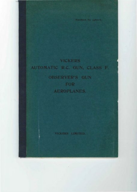
3<br />
<strong>Vickers</strong> Automatic Rifle Calibre<br />
Gun.<br />
(Class F.)<br />
Special Features.<br />
The <strong>Vickers</strong> Automatic R.C. Gun, Class F , is an<br />
air-cooled gun arranged to be supplied with ammunition<br />
from a drum-shaped m agazine attached to the<br />
top of the gun.<br />
The gun and ammunition being self-contained,<br />
this weapon forms a highly efficient arm for use in the<br />
gun cockpit of an aeroplane, where it is essential for<br />
the gun to be easily and freely manceuvred.<br />
The magazine has a capacity of 97 rounds, and is<br />
easily attached to or removed from the gun.<br />
The energy for working the gun automatically is<br />
obtained from the recoil of the barrel. Except for the<br />
feed, the action is the same as the well-tried standard<br />
<strong>Vickers</strong> R. C. belt-fed gun ; in fact , the recoiling parts,<br />
with the exception of the barrel, are exactly the same<br />
as the <strong>Vickers</strong> belt-fed R. C. gun.<br />
An in1portant feature is that, by the interchange<br />
of a few parts, the gun may readily be converted to<br />
a belt-fed weapon, and used by the pilot for synchronized<br />
fire through the propeller.<br />
It will readily be seen that having both fixed and<br />
manceuvrable guns on an aeroplane of the same<br />
system, and having the majority of their components<br />
the same, fewer spare parts and tools are necessary,<br />
and instruction in the working and maintenance of<br />
the guns is simplified.<br />
N ote.- Since this gun is air cooled, it must be<br />
fired only in short bursts (not exceeding 100 rounds)<br />
on the ground, time being allowed for cooling between<br />
the bursts.
4<br />
<strong>Vickers</strong> Automatic Rifle Calibre<br />
Gun.<br />
(Class F.)<br />
LIGHT l\IODEL F OR AEROPLA NES.<br />
General Description.<br />
The gun may be considered as divided into three<br />
portions, the non-recoiling : the recoiling and the feed<br />
mechanism. It is worked automatically by two<br />
forces : the explosion of the charge, which forces the<br />
recoiling portion backwards, and a strong spring<br />
(called the fuzee spring) whih carries it forward.<br />
The non-recoiling portion consists of the jacket and<br />
breech casing, and is attached t o the aeroplane<br />
mounting b y a trunnion pin.<br />
NoN-REcOILING P o RTION.<br />
J acket .- The jacket around the barrel is of steel,<br />
perforat ed to allow the passage of air to keep the<br />
barrel cool when firing.<br />
B reech Casing.- The breech casing consist s of t wo<br />
outside plat es , a bottom plate and a handle block , the<br />
whole being enclosed by t wo covers.<br />
The outside plat es are rivet ed t o the jacket. In<br />
both plates are slot s in which the crank bearings move,<br />
partly closed by filling-in pieces ; on the inside of<br />
both are cams which control the path of the extractor.<br />
On the outside of the right-hand plate are the following<br />
fittings :-<br />
R oller .- A roller, which revolves on a stud on the<br />
right filling-in piece, and is retained there by a washer<br />
.)<br />
and a pin. On t he outside of the left-hand plat e are<br />
two studs for attaching the fuzee spring bracket .<br />
B ottom P late.- The bottom plate is riveted to the<br />
outside plates and carries a bracket in which a spring<br />
loaded plunger is fitted.<br />
H andle Block.- The outside plates are connect ed<br />
at the rear end by a handle block, being held together<br />
by a screw pin which has a " T " shaped head to<br />
facilitate its removal. This pin is also used as a tool<br />
for assembling and dissembling the lock The handle<br />
block is fitted with a pistol grip containing the trigger<br />
and safety catch .<br />
R ear Cover.-The rear cover opens sideways, the<br />
cover hinges being on the left-hand side plate, parallel<br />
with the bore of the gun. The rear cover catch is on<br />
the top of the rear cover. It is operat ed by pressing<br />
inwards a spring-loaded plunger, to which is attached<br />
a lug which is thus disengaged from a corresponding<br />
hole in the right-hand side plate.<br />
Running in slots on the underside of the rear<br />
cover is the trigger bar, which, when actuated by the<br />
trigger in the pistol grip, actuates the firing mechanism<br />
in the lock.<br />
The trigger bar is kept in its normal position by<br />
a spring housed in the rear cover.<br />
It will be seen that it is impossible to fire the gun<br />
by pulling the trigger if the rear cover should be open.<br />
In the underside of the rear cover is a groove in<br />
which the top of the lock slides when the gun is working.<br />
Attached t o the inside of the rear cover, and<br />
projecting downwards, are the extractor guides, which,<br />
in conjunction with the cams on the side plates,<br />
control the path of the extractor.
G<br />
A portion of the front of the rear cover is cut<br />
avvay in order that the lock may be actu ated by a<br />
trigger motor should the gun b e converted t o fire<br />
ammunition fed by a belt for S.)mchronized fire.<br />
T runnion Bloch.- The two side plat es are connected<br />
togeth er at their front extremities by a trunnion<br />
block which forms a bearing for the breech end of the<br />
barrel. A hole is drilled just b eneath the barrel<br />
through both side plates and trunnion block, forming<br />
a bearing for the trunnion bolt, about which the gun<br />
is elevated or depressed . The jacket around the<br />
barrel is screwed in the front of the trunnion block.<br />
Nfuzzle A ttachme11t.- The muzzle attachment is<br />
screv,red on the end of the jacket . It consists of a<br />
cylinder through which is a hole concentric with the<br />
bore of the barrel. Its obj ect is to utilise th e force<br />
of the escaping prop elling gases from the barrel t o<br />
increase the force of recoil and reduce the flash.<br />
R ECOILING PORTION.<br />
The recoiling portion (which is mounted inside the<br />
non-recoiling portion) consists of the barrel and two<br />
recoil plates which carry the lock and the crank.<br />
B arrel.-The barrel is formed with a square<br />
block at the breech end, and is provided with two<br />
studs (one at each side) called the barrel trunnions.<br />
By means of these trunnions the barrel is connected<br />
to the recoil plates. The muzzle end of the barrel is<br />
supported in the b arrel sleeve.<br />
R ecoil Plates .- The recoil plates are each proYided<br />
with a hole to receive the barrel trunnions, and also<br />
guides in which the flanges of the lock move. The<br />
left recoil plate is ext ended t owards the front, and is<br />
formed at its end like a hook ; this hook engages with<br />
the connecting link which operates the feed plate.<br />
Crank B eariugs.- The recoil plates each have a<br />
bearing through which the crank axis passes, thus<br />
connecting the latter with the barrel; these bearings<br />
move in slots in the breech casing.<br />
E xtracto1/ Holdiug-up Sp1/ings.- The recoil plat es<br />
are fitted with extractor holding-up springs near the<br />
banel, the use of which is explained lat er.<br />
Crauk-The crank is fitted on the right with a<br />
handle, the upper surface of which bears on the roller,<br />
and is of a special curved form ; on the left it is fitted<br />
with a fuzee to which are attached two links. These<br />
links form the connections between the crank and the<br />
fuzee spring. The remainder of the crank is inside<br />
the breech casing.<br />
Connecting R od.- In the centre of the crank is a<br />
c?nnecting rod vvhich is free to revolve on the crank<br />
pm.<br />
Fuzee Spring.- On the left of the breech casing is<br />
a strong spiral spring called the fuzee spring, the<br />
rear end of which is connected (as before described)<br />
with the crank, and the fore end is attached t o the<br />
breech casing by means of the fuzee spring bracket<br />
and adjusting screw.<br />
The action of recoil extends the fuzee spring and<br />
winds the links, which are attached, to it about the<br />
fuzee; so that when the crank handle is right forward,<br />
the fuzee spring is not only ext ended about one inch<br />
by the recoil of the barrel, but the winding of the links<br />
on the fu zee causes a still further extension.<br />
As soon as the recoil is exhausted , the action of<br />
the fuzee spring is to pull the recoiling portion into<br />
the firing position, and t o umvind the links from the<br />
fuzee, thereby causing the crank handle to fly back.<br />
7
12<br />
surface o£ the bents on the extractor levers, thus<br />
giving an additional forward motion to the lock , and<br />
thereb y tightening up all the joints in the breech<br />
mechanism, and supporting it firmly against the<br />
breech at the instant of explosion.<br />
Cocki 11g Action.-The turning of the crank handle<br />
to the rear not only draws the lock away from the<br />
barrel, but also gi,·es an upward motion to the connecting<br />
rod and rear end of the side levers, which<br />
latter, bearing on the tail end of the tumbler, rotate<br />
it on its axis; and the head of the tumbler, being engaged<br />
in a recess in the firing pin, forces the latter to the rear,<br />
compressing the lock spring. '"'hen the bent of the<br />
tumbler has moved below the bent of the hand sear,<br />
the latter is forced to engage with it by the action of<br />
the lock spring, and it thus holds the tumbler in cocked<br />
position. The continued m otion of the tumbler carries<br />
back the firing pin until the safety sear (which is below,<br />
and is acted upon by the safety sear spring) is forced<br />
into the bent of the firing pin and retains it. The<br />
firing pin is thus prevented from flying forward by<br />
two actions, viz., that of the safet)· sear and that of<br />
the hand sear. -<br />
Firiug A ctio11.- 0n the crank handle returning,<br />
the lock mo,·es t o the front, and the connecting rod<br />
and rear end of side le,·ers have a downward motion;<br />
so that when the lock is in the forward position, the<br />
latter depresses the safet y sear, thereby disengaging<br />
it from the firing pin, which then moves slightly<br />
forward till stopped by the bent of the tumbler<br />
engaging the bent o£ the hand sear. If now the trigger<br />
is pulled , the trigger bar is drawn backwards, and, at<br />
the same time, a projection on the latter engages and<br />
draws with it the tail end of the hand sear, thereby<br />
releasing the tumbler ; the lock spring then propels<br />
the firing pin on to the cap and explodes the cartridge.<br />
If pressure on the trigger is maintained as the lock<br />
moves forward, the upper end of the hand sear comes<br />
13<br />
in contact with the projection on the trigger bar, and<br />
its bent is thus withdrawn from the tumbler before<br />
the extractor has reached the firing position ; the<br />
firing pin is therefore held by the safety sear only; and<br />
when the latter is depressed by the rear end of side<br />
levers, it is released, and is thrown forward on to the<br />
cap by the action of the lock spring. The release of<br />
the safet y sear from the firing pin is so timed that it<br />
cannot take place until after the lock is in the firing<br />
position, and has been tighten ed up against the breech<br />
by the last movement of the crank, which causes the<br />
points of the side le, ·ers to engage the inclines on the<br />
bent of the extractor leYers, as abo,·e described.<br />
Action of F eed l.VI echanis11t.- \"'hen the barrel<br />
recoils, the lug on the left-hand recoil plate actuates<br />
the connecting link, thus causing the feed plate<br />
to move about its axis in an anti-clockwise direction<br />
through the m edium of the connecting link. The<br />
actuating pawl on the feed plat e slips over the projection<br />
around the drum, and engages with a groove.<br />
At the sam e time the front retaining pawl is brought<br />
out of engagement with the drum, by reason of the<br />
projection of the feed plate. On the return of the<br />
barrel, the feed plate returns to its original position ;<br />
the actuating pawl being in engagement with the drum,<br />
the drum rotates with it a distance equal to the pitch<br />
of the grooves around its periphery. The drum is now<br />
held in tlus position by the ret aining pawls on the<br />
cover plate. The rot ation of the drum causes a<br />
cartridge to be forced out of the end of the helical<br />
tsroove in the drum centre, under the cartridge guide<br />
m the cover plate, and into the feed box. The cartridge<br />
is then pushed into the centre of the feed box by<br />
means of the feed p awls on the feed plate, where it is<br />
ready to be withdravvn by the extractor.
22<br />
To remedy, strike down sharply on the crank<br />
handle with a glancing blow to prevent injuring hand.<br />
If this fails, raise the crank handle slowly until the<br />
horns of the extractor are retained by the recess in the<br />
cams. The feed block should then be examined.<br />
Allow crank handle to go fonvard and :fire.<br />
If both fail, examine feed block. The probable<br />
cause of the failure is clue to the cartridge not passing<br />
freely through the feed block, or it may be due to<br />
faulty use of the loading plunger.<br />
Pull the crank handle fully back with loading<br />
plunger in operation and let go.<br />
If this fails, it is possible that a broken gib or gib<br />
spring is the cause. In this case the lock must be<br />
remo,·ed and replaced by spare one.<br />
--{:<br />
'<br />
Diagram 3. This st oppage is probably due t o a<br />
separated case. The front portion of the case is<br />
t elescoped on to the next cartridge in the chamber.<br />
To clear, raise rear cover , draw back crank<br />
handle and holding-up lock , push out cartridges from<br />
the extractor by butt end of clearing plug, close rear<br />
cover, release crank handle. R eload with the loading<br />
plunger in operation.<br />
If the separated case remains in the chamber the<br />
clearing plug must be used .<br />
23<br />
-\<br />
'<br />
I 4<br />
Diagram 4. This is due to defective ammunition,<br />
such as vveak charge or deteriorated ammunition, or<br />
excessive friction due to congealed oil.<br />
To clear after a stoppage, pull back the crank<br />
handle on to the roller and let go. If failure recurs<br />
repeat until gun is warmed up.<br />
It is obvious, to clear stoppage in the air, the<br />
gunner must be thoroughly trained in the mechanism<br />
of the gun and the causes of the various stoppages.<br />
In order to minimise the causes of stoppage the<br />
ammunition should be carefully tested, and only<br />
correct rounds should be fliled into the drums.<br />
The following extremely unlikely events would<br />
cause prolonged stoppages :-<br />
(1) Loose or broken muzzle attachment.<br />
(2) Broken fuzee or fuzee spring.<br />
Points to be Observed Before, During and<br />
After a Flight.<br />
(1) See that the barrel is clean and dry .<br />
(2) Oil the fr?:ctional parts lightly with a nonfreezing<br />
l?ltbricant, samples of zvhich zcill be supplied on<br />
application.<br />
(3) Check the weight on the crank handle with<br />
the spring balance. This must not exceed 6. 5 kgs.
10<br />
2 5 14 4<br />
4


