q-117r2 sve bulletin - South Bay Riders
q-117r2 sve bulletin - South Bay Riders
q-117r2 sve bulletin - South Bay Riders

Create successful ePaper yourself
Turn your PDF publications into a flip-book with our unique Google optimized e-Paper software.
Q-117R2<br />
SVE BULLETIN<br />
SPECIAL VEHICLE ENGINEERING – BODY BUILDERS ADVISORY SERVICE<br />
E-Mail via website: www.fleet.ford.com/truckbbas (click "Contact Us")<br />
Toll-free: (877) 840-4338<br />
QVM Bulletin: Q-117-R2 Date: 18 June, 2010<br />
2011 F-Series Super Duty Upfitter Switches<br />
Models Affected All 2011 and later Model Year F-250/350/450/550.<br />
Purpose<br />
To utilize Ford Upfitter Switches on F-Series Super Duty trucks.<br />
Description<br />
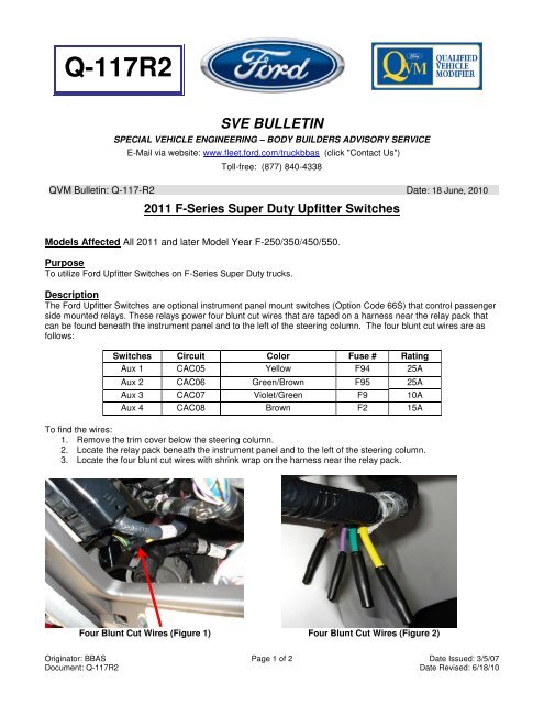
The Ford Upfitter Switches are optional instrument panel mount switches (Option Code 66S) that control passenger<br />
side mounted relays. These relays power four blunt cut wires that are taped on a harness near the relay pack that<br />
can be found beneath the instrument panel and to the left of the steering column. The four blunt cut wires are as<br />
follows:<br />
Switches Circuit Color Fuse # Rating<br />
Aux 1 CAC05 Yellow F94 25A<br />
Aux 2 CAC06 Green/Brown F95 25A<br />
Aux 3 CAC07 Violet/Green F9 10A<br />
Aux 4 CAC08 Brown F2 15A<br />
To find the wires:<br />
1. Remove the trim cover below the steering column.<br />
2. Locate the relay pack beneath the instrument panel and to the left of the steering column.<br />
3. Locate the four blunt cut wires with shrink wrap on the harness near the relay pack.<br />
Four Blunt Cut Wires (Figure 1) Four Blunt Cut Wires (Figure 2)<br />
Originator: BBAS Page 1 of 2 Date Issued: 3/5/07<br />
Document: Q-117R2 Date Revised: 6/18/10
Operating Procedure<br />
The Upfitter Switches are operational when the ignition key is in the "RUN" position only. The power to the switches<br />
is relay controlled and was designed to operate in the "RUN" mode to reduce the possibility of draining the<br />
battery/batteries.<br />
Upfitter Switch Wiring Diagram (Figure 3)<br />
If you have any questions, please contact the Ford Truck Body Builders Advisory Service as shown in the header of<br />
this <strong>bulletin</strong>.<br />
Originator: BBAS Page 2 of 2 Date Issued: 3/5/07<br />
Document: Q-117R2 Date Revised: 6/18/10