Antifriction Bearings Linear Systems - Franke GmbH
Antifriction Bearings Linear Systems - Franke GmbH
Antifriction Bearings Linear Systems - Franke GmbH

You also want an ePaper? Increase the reach of your titles
YUMPU automatically turns print PDFs into web optimized ePapers that Google loves.
Technical Information<br />
Technical Information<br />
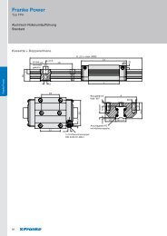
Type FR – <strong>Franke</strong> Robust<br />
1 Designs and System Description<br />
Aluminium Recirculating Ball Guides of type FRA comprise two<br />
individual rails and recirculating elements (see illustration 1).<br />
The recirculating elements are mounted on the mating plate and<br />
together form the carriage. The construction of the mating plate<br />
is specified by the customer.<br />
Illustration 1: Aluminium Recirculating Ball Guide<br />
Guides of the type FRA are particularly robust and have<br />
high load capacity. The max. traverse speed is 3 m/s, the<br />
max. acceleration is 30 m/s². Use is possible in a temperature<br />
range of –10 °C to +80 °C.<br />
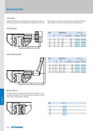
The slide resistance can be adjusted for <strong>Linear</strong> Guides of<br />
the type FRA. The fixing screws on the slider plate on the<br />
adjustment side must be loosened. Using an optional tool the<br />
recirculating element can be moved towards the carriage plate<br />
and the adjustment is altered. The adjustment setting is best<br />
determined by measuring the slide resistance in the unloaded<br />
state.<br />
The adjustment values are shown in table 5 Slide Resistances.<br />
Further details on fitting and adjusting the guide are given in<br />
the instruction manual for the Aluminium Recirculating Ball<br />
Guides.<br />
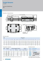
2 Dimensioning the Guides<br />
The following parameters are needed for correct dimensioning<br />
of the guide:<br />
• Selection of formation (see illustration 2)<br />
• All invasive or emerging forces / torques (dynamic / static)<br />
• Type of load (stationary, swelling, changing)<br />
• Environmental influences (e.g. temperature, moisture) or<br />
special operating conditions (e.g. clean room, vacuum)<br />
• Traverse speed and acceleration<br />
• Stroke length<br />
• Target lifetime in km<br />
112<br />
Illustration 2: Overview Formations<br />
All forces and torques must be within the permissible limits.<br />
The relevant data are on the pages for the individual types.<br />
Recommended safeties (for screw quality 8.8):<br />
• Pressure load: s > 1.2<br />
• Tension load: s > 2.5<br />
• Moment load: s > 4.0<br />
Calculations can be performed by <strong>Franke</strong>.<br />
3 Notes for Mating Structure<br />
3.1 Mounting Surfaces<br />
Contact and support surfaces essentially determine the function<br />
and precision of the guide. Inaccuracies can be added for<br />
running accuracy of the guide system. Therefore, the linearity<br />
and parallelism of the mating structure must be considered.<br />
The maximum permissible deviation across the whole stroke is<br />
0.04 mm.<br />
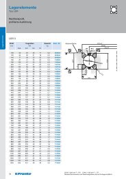
3.2 Fixing the Rails<br />
The rails are fixed against a bearing shoulder and screwed (see<br />
illustration 3). The two guide rails must be fitted parallel to one<br />
another. This is how you control the linearity and parallelism of<br />
the rails. The maximum total error must be less than 0.06 mm.<br />
Illustration 3: Fixing Rails