Antifriction Bearings Linear Systems - Franke GmbH
Antifriction Bearings Linear Systems - Franke GmbH
Antifriction Bearings Linear Systems - Franke GmbH

Create successful ePaper yourself
Turn your PDF publications into a flip-book with our unique Google optimized e-Paper software.
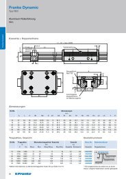
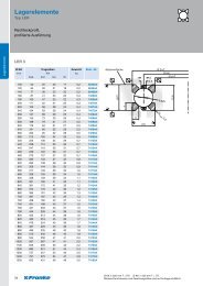
Technical Information<br />
Technical Information<br />
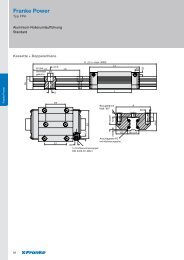
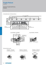
3.4 Fixing the Rails<br />
Depending on the type of load the guide rails should either:<br />
1. be screwed<br />
2. be screwed and pinned<br />
3. be laid against a contact shoulder and screwed<br />
(illustration 6).<br />
Illustration 6: Fixing Rails<br />
The load capacity of the rails is influenced by the connections<br />
between the guide elements and the mating structure. Fixing to<br />
the mating structure is effected using screws of quality 8.8 with<br />
plain washers DIN 433.<br />
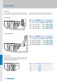
3.5 Fitting Instructions Coupled Rails<br />
Rails over a length of 4000 mm are coupled according to <strong>Franke</strong><br />
standards. Division according to <strong>Franke</strong> standards guarantees a<br />
universally even bore shape and optimum usage of the rail<br />
length. Divisions are also possible to customer specifications.<br />
Coupled rails are specially aligned with one another. Therefore,<br />
the rails have sequential numbering for the right fitting (e. g.<br />
A/1-1/1-2/2-2/E).<br />
Illustration 7: Coupled Rails /Auxiliary Cylinders<br />
108<br />
The rails are also marked with a groove on the rail underside,<br />
which must always be on the same side. The rails must be<br />
arranged free of play. The corresponding auxiliary cylinders<br />
(illustration 7) are used for this. The dimensions for the design<br />
of the auxiliary cylinders are in table 3. The cylinders are<br />
inserted at the joints of the rails in the raceway and preloaded<br />
using a device.<br />
Size Auxiliary Cylinder<br />
mm<br />
12 11<br />
15 11<br />
20 14<br />
25 16<br />
35 27<br />
45 35<br />
Table 3: Dimensions Auxiliary Cylinder<br />
The relevant tightening torques for the individual screws are<br />
given in table 4.<br />
Screws Tightening Torque<br />
M 3 1.1<br />
M 4 2.5<br />
M 5 5.0<br />
M 6 8.5<br />
M 8 21.0<br />
M10 41.0<br />
M12 71.0<br />
Table 4: Tightening Torques Screws<br />
3.6 Slide Resistances<br />
Size Slide Resistance<br />
N<br />
FDA FDB FDC FDD FDE FDG FDH<br />
12 Min. 0.2 0.2 0.5 – 0.5 0.6 –<br />
Max. 0.4 0.4 1.0 – 3.0 0.9 –<br />
15 Min. 0.5 0.5 0.5 – 1.0 0.5 –<br />
Max. 2.0 1.0 2.0 – 3.0 1.5 –<br />
20 Min. 1.0 0.5 1.0 – 1.0 1.0 –<br />
Max. 2.5 1.5 2.5 – 3.0 3.0 –<br />
25 Min. 1.5 0.5 1.5 1.5 1.5 0.5 2.5<br />
Max. 3.0 2.0 3.0 3.0 3.0 2.0 5.0<br />
35 Min. 2.0 1.0 2.0 – 2.0 1.0 4.0<br />
Max. 4.0 2.5 4.0 – 4.0 2.5 7.0<br />
45 Min. 2.5 2.0 3.5 – 2.5 2.0 5.0<br />
Max. 5.0 4.0 10.5 – 5.0 4.0 8.0