Antifriction Bearings Linear Systems - Franke GmbH
Antifriction Bearings Linear Systems - Franke GmbH
Antifriction Bearings Linear Systems - Franke GmbH

Create successful ePaper yourself
Turn your PDF publications into a flip-book with our unique Google optimized e-Paper software.
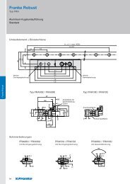
Illustration 4: Overview Formations<br />
Recommended safeties (for screw quality 8.8):<br />
• Pressure load: s > 1.2<br />
• Tension load: s > 2.5<br />
• Moment load: s > 4.0<br />
3 Notes for Mating Structure<br />
3.1 Mating Plate for Type FD<br />
A mating plate (continuing construction) must also be used<br />
when using single rails and roller shoes. The roller shoes and<br />
the mating plate together form the carriage.<br />
Note on layout of the mating plate of the carriage:<br />
the roller shoes have centering grooves for better alignment<br />
during assembly. You apply a centering bar to the mating plate<br />
for this purpose (illustration 5). The dimensions for producing<br />
the centering bar are in table 1. All other dimensions, tolerances<br />
and accuracies for the guides are given on the relevant pages<br />
of the catalogue.<br />
Illustration 5: Centering Shoulder<br />
Size a b<br />
mm mm<br />
12 4.5 9.6<br />
15 5.0 12.6<br />
20 7.5 16.1<br />
25 10.5 17.6<br />
35 12.5 26.1<br />
45 15.5 31.1<br />
Table 1: Dimensions Centering Bar<br />
3.2 Multi-Track Formations<br />
It is recommended to define a fixed and movable bearing site<br />
on the carriage plate for multi-track formations. This is the best<br />
way to equalise tolerances between the rails.<br />
For example, the movable bearing side can be designed with<br />
a carrier and a stroke safety. The fixed bearing side takes on the<br />
guide function, the movable bearing side equalises parallelism<br />
and height tolerances. It is recommended to locate the drive in<br />
direct proximity to the guide side, as the drive torque is taken<br />
from this.<br />
3.3 Mounting Surfaces<br />
Contact and support surfaces essentially determine the function<br />
and precision of the guide. Inaccuracies can be added for<br />
running accuracy of the guide system. For example, double-track<br />
formations require precise parallelism and height alignment. The<br />
accuracies for the mounting and contact surfaces of the guides<br />
from table 2 must be maintained to guarantee running accuracy<br />
of the guide:<br />
Size 12–20 25–45<br />
mm mm<br />
Max. tolerance for parallelism 0.03 0.05<br />
Max. evenness mounting surface 0.10 0.20<br />
Table 2: Accuracies Contact and Support Surfaces<br />
107<br />
Technical Information