Antifriction Bearings Linear Systems - Franke GmbH
Antifriction Bearings Linear Systems - Franke GmbH
Antifriction Bearings Linear Systems - Franke GmbH

You also want an ePaper? Increase the reach of your titles
YUMPU automatically turns print PDFs into web optimized ePapers that Google loves.
An invention prevails.<br />
<strong>Antifriction</strong> <strong>Bearings</strong><br />
<strong>Linear</strong> <strong>Systems</strong>
Our standard: the unusual.
The Guided Roller ®<br />
for perfect interaction:<br />
rollers with nuts,<br />
which match the<br />
raceway precisely.<br />
<strong>Linear</strong> <strong>Systems</strong><br />
Perfection from principle.<br />
Aluminium <strong>Linear</strong> <strong>Systems</strong> from <strong>Franke</strong> are the best solution when you need<br />
translational motion. The essential components of these durable systems:<br />
Aluminium <strong>Linear</strong> <strong>Systems</strong>, specially designed raceways, cassettes or pairs<br />
of roller shoes with rollers.<br />
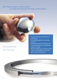
Thanks to the patented guide system, the rollers are perfectly placed in<br />
the guide rails on four raceways. The 4-point contact takes loads from<br />
all directions.<br />
The range:<br />
• <strong>Systems</strong> with O-arranged rollers<br />
• <strong>Systems</strong> with 2 rows of recirculating rollers<br />
• <strong>Systems</strong> with 1 row of recirculating balls<br />
• <strong>Linear</strong> Tables and <strong>Linear</strong> Modules
The main attraction:<br />
rolling elements, which<br />
circulate smoothly on<br />
precisely calibrated<br />
race rings.<br />
<strong>Antifriction</strong> <strong>Bearings</strong><br />
Patented precision.<br />
Mechanical processes are circular; our bearings make it possible. They<br />
comprise four race rings, balls, a ball cage and, on request, enclosed design.<br />
They are based on a patented principle: four race rings form the heart of the<br />
bearing. Thanks to a specially developed grinding procedure they fit their<br />
raceway – exactly adjusted to the ball diameter. Therefore, the rolling process<br />
does not occur directly between the rolling elements and enclosed design, but<br />
rather smoothly on the four open race rings. Thanks to the 4-point contact,<br />
the systems can take loads of any level from all directions.<br />
The bearings range:<br />
• Bearing elements that fit directly into existing designs<br />
• Slim bearing to international standards<br />
• Pre-finished bearing assemblies with good centre freedom<br />
• Powered units with measuring equipment and control<br />
The <strong>Franke</strong> Principle
Dear Customers and Interested Parties!<br />
“An invention prevails” – this slogan is a dedication to our company<br />
founder Erich <strong>Franke</strong>, who invented the four-point bearing element in<br />
the 1930s. And it still applies to this day. In close cooperation with our<br />
customers, new solutions for <strong>Franke</strong> <strong>Antifriction</strong> <strong>Bearings</strong> and Aluminium<br />
<strong>Linear</strong> <strong>Systems</strong> emerge daily, new products are developed and new<br />
markets are accessed across the globe.<br />
We developed many of our products for a specific application. Others<br />
are incorporated into standard ranges and can be ordered directly from<br />
the catalogue.<br />
With this catalogue, we would like to give you a comprehensive view of<br />
our product range and our company. Learn how we match our products<br />
specifically to customers’ needs, which advantages will benefit you, how our<br />
bearings and guide systems are constructed and much more. Application<br />
examples from industries, such as medical technology, textiles and clean<br />
room technology, also reveal the diverse applications of our <strong>Antifriction</strong><br />
<strong>Bearings</strong> and <strong>Linear</strong> <strong>Systems</strong>.<br />
We would also be delighted to develop the perfect solution for your<br />
application, following in the footsteps of Erich <strong>Franke</strong> and his inventive<br />
talent.<br />
Best wishes<br />
Daniel Groz Sascha Eberhard<br />
Daniel Groz Sascha Eberhard<br />
Managing Director Managing Director<br />
3
<strong>Linear</strong> <strong>Systems</strong> at a Glance<br />
Type<br />
Components<br />
Options<br />
Advantages<br />
Sizes (mm)<br />
Standard<br />
Special<br />
Travelling speed<br />
Vmax (m/s)<br />
Acceleration (m/s 2 )<br />
Rail length (mm)<br />
one-piece<br />
More on page 78 – 79<br />
65<br />
Roller Guide<br />
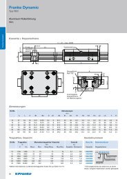
<strong>Franke</strong> Dynamic<br />
FDA<br />
Standard<br />
Use • For high loads<br />
in all applications<br />
• Aluminium body material for cassettes, roller shoes and guide raceways<br />
• Plastic wiper with felt insert on both front sides of the cassettes or roller shoes<br />
• Steel raceways • Steel raceways • Non-corrosive • Non-magnetic<br />
• Needle bearing • Ball bearing rollers raceways<br />
raceways<br />
rollers<br />
• Needle bearing non- • Needle bearing<br />
corrosive rollers rollers<br />
12 – 45<br />
10<br />
40<br />
4000<br />
FDB<br />
Low cost<br />
• For low loads<br />
in all applications<br />
12 – 45<br />
10<br />
40<br />
80 – 81<br />
FDC<br />
Non-corrosive<br />
• For medium<br />
loads in moist<br />
or aggressive<br />
environment<br />
15 – 45<br />
10<br />
40<br />
82 – 83<br />
FDD<br />
Non-magnetic<br />
• Special guide profiles<br />
• Surface coating of the raceways and cassettes<br />
• Customer-specific connection borings<br />
• Metal wipers<br />
• Bellow covers<br />
• Extended cassettes and roller shoes for higher loads<br />
• Connections for central lubrication<br />
• Individual design of the cassettes (e.g. with spindle acceptance or connection of measuring systems)<br />
• High-load raceways for use with linear motors<br />
• Easier and quieter running thanks to large-size rollers<br />
• Fast response behaviour<br />
• No stick-slip effect<br />
• Slide resistance can be adjusted up and down<br />
• Aluminium body materials harmonise perfectly with aluminium carrier profiles and facilitate design<br />
of lighter constructions<br />
• High precision • Reasonable price • Corrosion-resistant • Non-magnetic<br />
• High load capacity<br />
materials<br />
• Sizes and special shapes for series production at customer’s request<br />
• Can be continuously coupled for longer stroke<br />
• For light loads in<br />
25<br />
2<br />
10<br />
magnetic fields or<br />
radiation rooms<br />
84 – 85<br />
FDE<br />
Lubricant-free<br />
• Steel raceways<br />
• Lubricant-free<br />
rollers<br />
• For medium loads<br />
under extremely<br />
hygienic<br />
conditions<br />
12 – 45<br />
4000 4000 4000 4000<br />
• Lubricant-free<br />
and clean<br />
1<br />
10<br />
86 – 87
FDG<br />
Non-corrosive<br />
low cost<br />
• Non-corrosive<br />
raceways<br />
• Ball bearing noncorrosive<br />
rollers<br />
• Corrosion-resistant<br />
• Reasonable price<br />
• For low loads in<br />
12 – 45<br />
10<br />
40<br />
moist or aggressive<br />
environment<br />
88 – 89<br />
66<br />
FDH<br />
High dynamic<br />
• Steel raceways<br />
• 2-row bearing<br />
rollers<br />
• For high loads and<br />
25 – 45<br />
10<br />
40<br />
4000 4000<br />
• Fast response<br />
behaviour<br />
high accelerations<br />
90 – 91<br />
Recirculating Rollers<br />
<strong>Franke</strong> Power<br />
FPA<br />
Standard<br />
• Aluminium body material<br />
• Steel raceways<br />
• 2 rows of recirculating rollers,<br />
arranged at 90° angles<br />
• Plastic wiper<br />
• Lubricating nipple<br />
• Slide resistance set ex<br />
• High stiffness<br />
• High load capacity<br />
• High moment load rating<br />
• All-round sealing<br />
• Relubrication possible via<br />
funnel-type lubricating nipple<br />
• Lubrication connection<br />
possible on 4 sides<br />
• For high loads and<br />
moment loading in<br />
heavy load operation<br />
92 – 93<br />
FRA<br />
Standard<br />
25 06 – 13<br />
3<br />
40<br />
works<br />
• Cassette prefitted on<br />
raceway<br />
4000<br />
continuously coupled<br />
Recirculating Ball Guide<br />
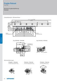
<strong>Franke</strong> Robust<br />
• Aluminium body material<br />
• Steel raceways<br />
• 1 row of recirculating balls,<br />
balls with dividers<br />
• Felt wiper<br />
• Non-corrosive or non-<br />
• High load rating<br />
• High lifetime<br />
• Robust also under severe<br />
conditions<br />
• Shock and impactresistant<br />
• High stiffness<br />
• For applications with the<br />
highest loads in harsh<br />
environments<br />
3<br />
30<br />
magnetic raceways<br />
• Bore shape to<br />
specifications<br />
4000<br />
continuously coupled<br />
94 – 95<br />
<strong>Systems</strong><br />
FTB, FTC, FTD<br />
• <strong>Linear</strong> Modules, <strong>Linear</strong><br />
Tables, powered <strong>Linear</strong><br />
Guides, motors, rotary<br />
encoders, CNC controls<br />
• Integrated <strong>Franke</strong> <strong>Linear</strong><br />
<strong>Systems</strong><br />
• Complete multi-axle<br />
systems<br />
• Mounting angle<br />
• Measuring systems<br />
• Special sizing and bore<br />
shapes available for series<br />
production<br />
• Free choice of<br />
motorisation<br />
• For automation, measuring<br />
15 – 35<br />
10<br />
40<br />
and testing applications,<br />
recirculating, processing,<br />
mounting<br />
7000<br />
–<br />
96 – 101<br />
<strong>Linear</strong> <strong>Systems</strong> at a Glance
<strong>Linear</strong> <strong>Systems</strong><br />
Page<br />
Overview, Examples of Use, Advantages/Characteristics 65 – 77<br />
<strong>Franke</strong> Dynamic<br />
Type FDA Standard 78 – 79<br />
Type FDB Low cost 80 – 81<br />
Type FDC Non-corrosive 82 – 83<br />
Type FDD Non-magnetic 84 – 85<br />
Type FDE Lubricant-free 86 – 87<br />
Type FDG Non-corrosive low cost 88 – 89<br />
Type FDH High dynamic 90 – 91<br />
<strong>Franke</strong> Power<br />
Type FPA Standard 92 – 93<br />
<strong>Franke</strong> Robust<br />
Type FRA Standard 94 – 95<br />
<strong>Linear</strong> Tables/Modules<br />
FTB Standard 96 – 97<br />
FTC Standard 98 – 99<br />
FTD High dynamic 100 – 101<br />
Accessories<br />
Guides 102 – 103<br />
Modules 104 – 105<br />
Technical Information<br />
<strong>Franke</strong> Dynamic 106 – 109<br />
<strong>Franke</strong> Power 109 – 111<br />
<strong>Franke</strong> Robust 112 – 113<br />
<strong>Linear</strong> Tables/Modules 114<br />
67<br />
Accessories <strong>Linear</strong> Tables/Modules <strong>Franke</strong> Robust<br />
<strong>Franke</strong> Power<br />
<strong>Franke</strong> Dynamic<br />
Technical Information
<strong>Linear</strong> <strong>Systems</strong> in Practice<br />
The <strong>Franke</strong> principle of the guided roller guarantees easy and silent running, even at high speeds.<br />
These factors are essential for smooth production in many industries. Therefore, <strong>Franke</strong> <strong>Linear</strong><br />
<strong>Systems</strong> are also used in the most diverse industrial sectors – for example in medical technology,<br />
the food industry, for machine and plant engineering or in the handling sector.<br />
In Medical Technology:<br />
Dental X-Ray Equipment<br />
Precise x-rays need the movement of the light unit to be<br />
completely vibration-free. Therefore, the roller guide used<br />
must have smooth and silent running. The <strong>Franke</strong> Dynamic<br />
Aluminium Roller Guide fulfils this demand perfectly.<br />
The Features:<br />
• The <strong>Franke</strong> Dynamic Aluminium Roller Guide has lifetime<br />
lubrication.<br />
• Sealed rollers prevent the lubricant escaping.<br />
• The guide’s running is silent, smooth and even.<br />
• Preloading the cassette ensures vibration-free movement<br />
of the secondary light.<br />
68<br />
In Plant Engineering:<br />
Packaging Machines<br />
The <strong>Franke</strong> Dynamic Aluminium Roller Guide is also used<br />
on packaging machinery for mattresses. In addition to<br />
cleanliness, the mobile function of the guide unit must be<br />
ensured, to avoid soiling the mattresses.<br />
The Features:<br />
• The <strong>Franke</strong> Dynamic Aluminium Roller Guide is<br />
maintenance-free and requires no relubrication.<br />
• No lubricant can escape from the encapsulated rollers.<br />
• The guide is available in a completely lubricant-free<br />
design on request.
In the Food Industry:<br />
Cheese Production<br />
In cheese production the food-safe <strong>Franke</strong> Dynamic<br />
Aluminium Roller Guide provides the vertical movement<br />
of a grappler for wheels of cheese. In this application it is<br />
important that the roller guide is insensitive to whey and<br />
aggressive cleaning agents.<br />
The Features:<br />
• The guide is insensitive to moisture.<br />
• Its running is easy and silent, the drive power is low.<br />
• No maintenance and lubrication for the whole lifetime<br />
are guaranteed.<br />
• An integrated wiper fulfils the specific hygiene<br />
requirements for food production.<br />
• The product is available in a lubricant-free version<br />
on request.<br />
In the Packing Industry:<br />
Packaging Machines<br />
A bag forming, filling and sealing machine works at high<br />
speeds. It has stroke lengths of 1500 to 2100 mm, the average<br />
service performance is 30000 kilometers a year. The <strong>Franke</strong><br />
Dynamic Aluminium Roller Guide used must be resistant to<br />
the aggressive environmental conditions, such as salt, sugar<br />
and splash water.<br />
The Features:<br />
• The <strong>Franke</strong> Dynamic Aluminium Roller Guide is in a<br />
position to realise speeds up to 10 m/s.<br />
• Several guides can be coupled for any length of stroke<br />
desired.<br />
• A good lifetime and service performance are achieved<br />
through central lubrication of the cassette.<br />
69
<strong>Linear</strong> <strong>Systems</strong> in Practice<br />
In the Handling Sector:<br />
Pick&Place Robots<br />
Aluminium Roller Guides of type FDA 15 are used for this<br />
handling unit. The linear motor is integrated in a steel profile.<br />
The roller shoes are part of the housing and guide the<br />
profile.<br />
The Features:<br />
• High accelerations up to 70 m/s² are possible.<br />
• The <strong>Franke</strong> Dynamic Aluminium Roller Guide guarantees<br />
precise repeat accuracies of +/–0.01 mm.<br />
• Positioning of workpieces is quick and precise.<br />
• The guide’s low space requirement facilitates the compact<br />
design of the linear drive.<br />
• No maintenance and cleanliness are guaranteed.<br />
70<br />
In the Handling Sector:<br />
High Speed Camera Guiding<br />
The <strong>Franke</strong> Dynamic Aluminium Roller Guide moves the high<br />
speed camera for a film printing machine. A results check is<br />
performed during the printing process by camera or video.<br />
As films of different widths are printed, the camera must be<br />
easy to position.<br />
The Features:<br />
• The <strong>Franke</strong> Dynamic Aluminium Roller Guide has smooth,<br />
even running.<br />
• It weighs very little as the body material of the rail is<br />
aluminium.<br />
• Special borings guarantee connection to the path<br />
measuring system.
In Machinery:<br />
Ring and Drum Coilers<br />
The <strong>Franke</strong> Power Aluminium Recirculating Roller Guide is<br />
used for machines that process and pack coiled goods. It<br />
ensures that cables, hoses or steel ropes are coiled on rings<br />
or empty spools, measured to length and cut.<br />
The Features:<br />
• The <strong>Franke</strong> Power Aluminium Roller Guide has high<br />
load-capacity and stiffness.<br />
• The cassettes are completely sealed and are also suitable<br />
for harsh conditions.<br />
• Integrated metal wipers keep the raceways clean.<br />
In Machinery:<br />
Handling System<br />
Different processing centres are coupled together in this<br />
machine through large portals. Workpieces are processed<br />
with high acceleration. The <strong>Franke</strong> Robust Aluminium<br />
Recirculating Ball Guide is used in the transfer line. The<br />
recirculating ball system of type FRA10 and FRA13 harmonises<br />
perfectly with the substructure of aluminium profiles.<br />
The Features:<br />
• Transfer speeds of up to 3 m/s and accelerations of up to<br />
30 m/s² are achieved.<br />
• The <strong>Franke</strong> Robust Aluminium Recirculating Ball Guides<br />
used have a high lifetime, even in harsh and very dirty<br />
conditions.<br />
• Tolerances and unevenness in the substructure can be<br />
equalised to a certain extent.<br />
71
<strong>Franke</strong> Dynamic<br />
Aluminium Roller Guide – Advantages and Characteristics<br />
Type FDA – FDH<br />
The Characteristics:<br />
Cassettes and Roller Shoes<br />
The cassette of the <strong>Franke</strong> Dynamic Aluminium Roller Guide has<br />
aluminium body material with needle or ball bearing rollers of<br />
steel or non-corrosive. Special cover discs on the roller seal the<br />
bearing to the outside.<br />
Eight rollers in O-formation guarantee an equally high load<br />
capacity from all directions. The rollers are equipped with a<br />
groove, which is adjusted to the profile of the raceway. Thanks<br />
to this patented system of guided rolls, the rollers are guided<br />
laterally and equally smooth and silent running is guaranteed.<br />
The cassette plate has mounting holes in accordance with<br />
international standards. The slide resistance can be adjusted<br />
up and down individually using a setting screw on the side.<br />
Five standard sizes are available from size 12 to 45.<br />
72<br />
Aluminium body material<br />
for cassettes and<br />
guide rails<br />
Profiled raceways<br />
Guided rollers with<br />
groove in O-formation<br />
In the pair of single rails with roller shoes version there is no<br />
cassette plate. As a result, the guide width can be selected<br />
freely. The roller shoes are screwed directly to the mating<br />
strucure and facilitate extremely compact structures.<br />
Thread pieces for one-sided adjustability of the slide resistance<br />
are supplied and can be integrated.
The Advantages:<br />
• Low weight thanks to aluminium body material<br />
• Silent and easy running thanks to the patented Guided Roller ®<br />
• Maintenance-free and clean<br />
• O-formation for equal loads from all directions<br />
• High traverse speed and acceleration<br />
• Numerous variations for almost any application<br />
• Customer-specific solutions if series needed<br />
Wipers<br />
The bearings of the rollers are sealed and have lifetime<br />
lubrication. Thanks to the standard felt wiper, lasting<br />
protection of the guide system from soiling is guaranteed.<br />
Metal wipers are included as accessories, which are<br />
particularly recommended for coarse dirt such as chippings<br />
or sawdust and keep the raceway clean (see accessories<br />
page 102).<br />
Lubricant-free cassettes and roller shoes are available as type<br />
FDE. They are also suitable for hygienically sensitive sectors,<br />
for example the food industry or medical technology.<br />
Guide Rails<br />
The raceways of spring steel, non-corrosive or non-magnetic<br />
steel are integrated in the aluminium profile. The O-formation<br />
guarantees high load capacity from all directions. The profile<br />
of the rollers is adjusted to the raceway and guarantees<br />
permanently precise and smooth running.<br />
The guide rails are available in one piece up to a length of four<br />
meters. They can be continuously coupled for longer strokes.<br />
We can supply bore shapes specially tailored to your design<br />
on request.<br />
<strong>Franke</strong> precision raceways of spring steel, non-corrosive or<br />
non-magnetic steel can be integrated into a variety of aluminium<br />
profiles. We can supply your chosen profile complete with<br />
integrated raceways in series production.<br />
We also offer specially hardened raceways for the heaviest<br />
loads.<br />
73
<strong>Franke</strong> Dynamic<br />
Aluminium Roller Guide – Numerous Possibilities<br />
The Different Types:<br />
Type FDA Standard<br />
Type FDB Low cost<br />
Type FDC Non-corrosive<br />
Type FDD Non-magnetic<br />
Type FDE Lubricant-free<br />
Type FDG Non-corrosive low cost<br />
Type FDH High dynamic<br />
We can also supply special cassettes in specific dimensions,<br />
heat-resistant versions and vacuum-fit for series production.<br />
Please call us.<br />
Further Possibilities:<br />
Design<br />
For series production it is possible to adjust the shape and<br />
design of the cassettes, roller shoes and guide profiles to your<br />
individual application. You will get the perfect solution tailored<br />
to your requirements.<br />
Adjustment options are:<br />
• Shortened or extended roller shoes/cassettes<br />
• Special shapes, e. g. for integration of drives<br />
• Special profiles of guide rails according to your needs<br />
• Individual bore shapes on the guide rails<br />
• Fixing from underneath<br />
74<br />
Vacuum/High Temperature<br />
We also offer special cassettes and roller shoes for applications<br />
in vacuums. They are designed with free borings and equipped<br />
with lubricants suited to high vacuums on request.<br />
You can choose from a selection of special, heat-resistant<br />
cassettes and roller shoes for applications with radiant heat in<br />
the vicinity of heat sources.<br />
Temperature ranges up to 200 °C are possible.
Complete <strong>Systems</strong><br />
The <strong>Franke</strong> Dynamic Aluminium Roller Guides are also used<br />
in our complete systems of linear axle, drive, motorisation<br />
and control. <strong>Franke</strong> <strong>Linear</strong> Modules and <strong>Linear</strong> Tables use the<br />
assets of <strong>Linear</strong> <strong>Systems</strong> to build-up complete moving units.<br />
Clean Room<br />
The <strong>Franke</strong> Dynamic Aluminium Roller Guide was appraised<br />
and evaluated at the Institut für Produktionstechnik und<br />
Automatisierung (IPA) at the Fraunhofer Gesellschaft (FhG)<br />
in Stuttgart with regard to its operation in rooms with high<br />
air purity rates.<br />
The result: the <strong>Franke</strong> Dynamic Aluminium Roller Guide of type<br />
FDA is suitable for clean room-typical movement speeds for use<br />
in clean rooms with air purity classes “Class 1000”.<br />
Toothed belt gear <strong>Linear</strong> Modules are available up to a stroke<br />
length of 7000 mm. The integrated <strong>Franke</strong> Dynamic Aluminium<br />
Roller Guide provides high dynamic movements and easy and<br />
silent running.<br />
It is extremely suitable for the listed loading conditions. The<br />
trends of the results (e.g. particle emissions on increase of the<br />
moved mass) allow us to state that a suitability for “Class 1000”<br />
is also achieved for higher loads.<br />
75
<strong>Franke</strong> Power<br />
Aluminium Recirculating Roller Guide<br />
Type FPA<br />
The Advantages:<br />
• High load capacity and stiffness<br />
• Connecting dimensions compatible<br />
with international standards<br />
• Integrated metal wipers<br />
• All-round sealing<br />
The Characteristics:<br />
Cassette<br />
The cassette of the <strong>Franke</strong> Power Aluminium Recirculating<br />
Roller Guide is made from special aluminium with fixing bores<br />
in accordance with international standards and, therefore,<br />
is interchangeable with products from many manufacturers.<br />
Wear-resistant plastic seals provide all-round sealing for the<br />
cassette. The additional frontal metal wipers are adjusted<br />
to the rail contour and protect the guide system from coarse<br />
impurities.<br />
The recirculating rollers in 90°-formation guarantee even,<br />
high load capacity and loading from every direction. Each<br />
cassette has a lubrication nipple, which can be attached to<br />
one of the four front ends. A defined slide resistance ensures<br />
alignment on the guide rails. It is supplied with a preload class<br />
with light preload. The guides can be mounted on unprocessed<br />
surfaces without impairing the lifetime. The inner elasticity of<br />
the Recirculating Roller Guide is ensured by a system patented<br />
by <strong>Franke</strong>.<br />
76<br />
Integrated wiper and<br />
lubricating nipple<br />
Aluminium body material<br />
for the cassette and rail<br />
Profiled raceways<br />
Rollers in<br />
O-formation<br />
Guide Rails<br />
Raceways of spring steel, non-corrosive or non-magnetic<br />
steel are integrated in the aluminium profile. High load capacity<br />
from all directions is guaranteed by the O-formation. The profile<br />
of the rollers is adjusted to the raceway and ensures precise<br />
and easy running permanently.<br />
The guide rails can be supplied as one piece up to a length of<br />
four meters and can be coupled together endlessly for longer<br />
strokes. We can supply bore shapes specially tailored to your<br />
design on request.
<strong>Franke</strong> Robust<br />
Aluminium Recirculating Ball Guide<br />
Type FRA<br />
The Advantages:<br />
• High load capacity, high security<br />
• High lifetime and profitability<br />
• Robust, also in harsh conditions<br />
• Shock and impact-resistant<br />
The Characteristics:<br />
Recirculating Element<br />
The <strong>Franke</strong> Robust Recirculating Ball Guide proves itself in the<br />
most diverse applications and industries. It works reliably in<br />
machinery, in robotics, portals and in transport.<br />
The recirculating elements have a compact and robust design.<br />
The balls are kept apart by plastic wipers, which prevents any<br />
friction. The result: good running performance and long lifetime.<br />
The recirculating elements are screwed directly to the mating<br />
structure. By using individual rails, the range of the guide can be<br />
selected completely freely and adjusts to your specifi cations.<br />
Aluminium body material<br />
of the guide rail<br />
Ground raceways<br />
Recirculating ball<br />
element with<br />
steel body<br />
Guide Rails<br />
The high load capacity of the guide results from precise<br />
adjustment of the raceways to the balls. Embedded raceways<br />
of spring steel or non-corrosive adjust to the load and can<br />
be exchanged as needed. Thus, complete raceways can be<br />
replaced cheaply without dismantling the rails.<br />
Light-weight aluminium components are the best choice on<br />
large robots or handling portals. The <strong>Franke</strong> Robust Aluminium<br />
Recirculating Ball Guides combine light-weight construction<br />
with high load capacity and precision.<br />
The inner elasticity of the guide system means tolerances in<br />
the substructure of the portals or vibrations can be equalised.<br />
77
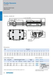
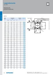
<strong>Franke</strong> Dynamic<br />
<strong>Franke</strong> Dynamic<br />
Type FDA<br />
Aluminium Roller Guide<br />
Standard<br />
Cassette + double rail<br />
Dimensions<br />
78<br />
Size Dimensions<br />
mm<br />
A L H B1 B2 D D1 D2 E1 E2 H1 H2 H3 H4 L2 L3 T T1<br />
12 37 64 19 12.0 12.50 3.4 6 M 4 25 30 14.7 4.0 1.4 5.5 10 40 5.5 8<br />
15 47 78 24 15.5 15.75 4.5 8 M 5 30 38 18.7 5.0 2.0 8.0 10 60 6.0 10<br />
20 63 92 30 21.0 21.00 5.5 10 M 6 40 53 22.6 7.0 2.0 11.0 10 60 8.0 12<br />
25 70 98 36 23.0 23.50 6.6 11 M 8 45 57 27.0 8.5 2.5 13.0 10 60 10.0 16<br />
35 100 135 48 32.0 34.00 9.0 15 M10 62 82 37.0 10.5 3.5 20.0 12 80 11.5 20<br />
45 120 165 60 45.0 37.50 11.0 18 M12 80 100 46.0 13.5 4.0 22.0 16 105 14.5 24<br />
Load ratings, weight<br />
Size Load ratings Moment load ratings* cassette Weight<br />
N Nm kg<br />
C Co Mocx Mcx Mocy/Mocz Mcy/Mcz Cassette rail/m<br />
12 2800 3000 27 25 43 40 0.1 0.4<br />
15 4200 3400 37 45 58 72 0.2 0.8<br />
20 5400 5400 76 76 111 111 0.4 0.9<br />
25 9000 10100 158 142 222 198 0.5 1.8<br />
35 12500 18000 423 294 559 388 1.4 3.2<br />
45 21200 25900 827 678 983 806 2.5 5.5<br />
*There is more information on moment load ratings on page 106/107.<br />
Order numbers<br />
Order no. Order key<br />
Cassette Double rail<br />
84494A<br />
84396A<br />
84441A<br />
84363A<br />
84364A<br />
84365A<br />
e.g. FDA 25 D 1500<br />
Type<br />
Size<br />
Length in mm**<br />
Double rail<br />
**Guide rails up to 4000 mm on one piece.<br />
Longer strokes are coupled.
Materials<br />
Dimensions<br />
Body material Rollers Wipers<br />
Standard High-strength, <strong>Antifriction</strong> Plastic plate<br />
anodized bearing steel with felt wiper<br />
aluminium<br />
Pair of roller shoes + single rail pairs<br />
Size Dimensions<br />
mm<br />
B5 H5 B3 B4 D3 D4 D5 E3 E4 E5 E6 E7 E8 E9 H6 T3 a b<br />
12 24.4 15.0 12.00 11.9 M3 8 3 3.4 29 57 9.7 3.4 5.5 4.9 4 6.0 4.5 9.5<br />
15 30.9 19.0 15.25 15.2 M4 10 4 4.4 34 68 12.4 4.9 7.0 5.9 5 7.5 5.0 12.5<br />
20 40.9 23.0 20.00 20.4 M5 10 4 4.9 42 80 16.9 5.9 9.5 5.9 5 8.0 7.5 16.0<br />
25 48.4 27.5 25.00 22.9 M5 14 6 6.4 48 84 19.4 7.4 12.0 8.9 7 5.0 10.5 17.5<br />
35 68.9 37.5 35.00 32.9 M6 14 6 8.9 67 117 28.4 8.9 17.0 8.9 7 7.5 12.5 26.0<br />
45 82.4 46.5 45.00 36.4 M8 14 6 9.9 83 146 30.9 9.9 22.0 8.9 7 9.5 15.5 31.0<br />
Load ratings, weight<br />
Size Load ratings Moment load ratings* RSP Weight<br />
N Nm kg<br />
C Co Mocx Mcx Mocy/Mocz Mcy/Mcz RSP rail/m<br />
12 2800 3000 1.5 (B+ 30.3) 1.4 (B+ 30.3) 43 40 0.07 0.4<br />
15 4200 3400 1.7 (B+ 36.5) 2.1 (B+ 36.5) 58 72 0.12 0.8<br />
20 5400 5400 2.7 (B+ 47.0) 2.7 (B+ 47.0) 111 111 0.23 1.0<br />
25 9000 10100 5.0 (B+ 58.4) 4.5 (B+ 58.4) 222 198 0.34 1.9<br />
35 12500 18000 9.0 (B+ 85.0) 6.3 (B+ 85.0) 559 388 0.99 3.5<br />
45 21200 25900 12.9 (B+109.0) 10.6 (B+109.0) 983 806 1.79 5.6<br />
Order numbers<br />
Order no. Order key<br />
RSP Single rail pair<br />
84495A<br />
84395A<br />
84442A<br />
84367A<br />
84368A<br />
84369A<br />
e.g. FDA 25 E 1500<br />
*There is more information on moment load ratings on page 106/107. **Guide rails up to 4000 mm on one piece.<br />
Longer strokes are coupled.<br />
Type<br />
Size<br />
Length in mm**<br />
Single rail<br />
79<br />
<strong>Franke</strong> Dynamic
<strong>Franke</strong> Dynamic<br />
<strong>Franke</strong> Dynamic<br />
Type FDB<br />
Aluminium Roller Guide<br />
Low cost<br />
Cassette + double rail<br />
Dimensions<br />
80<br />
Size Dimensions<br />
mm<br />
A L H B1 B2 D D1 D2 E1 E2 H1 H2 H3 H4 L2 L3 T T1<br />
12 37 64 19 12.0 12.50 3.4 6 M 4 25 30 14.7 4.0 1.4 5.5 10 40 5.5 8<br />
15 47 78 24 15.5 15.75 4.5 8 M 5 30 38 18.7 5.0 2.0 8.0 10 60 6.0 10<br />
20 63 92 30 21.0 21.00 5.5 10 M 6 40 53 22.6 7.0 2.0 11.0 10 60 8.0 12<br />
25 70 98 36 23.0 23.50 6.6 11 M 8 45 57 27.0 8.5 2.5 13.0 10 60 10.0 16<br />
35 100 135 48 32.0 34.00 9.0 15 M10 62 82 37.0 10.5 3.5 20.0 12 80 11.5 20<br />
45 120 165 60 45.0 37.50 11.0 18 M12 80 100 46.0 13.5 4.0 22.0 16 105 14.5 24<br />
Load ratings, weight Order numbers<br />
Size Load ratings Moment load ratings* cassette Weight<br />
N Nm kg<br />
C Co Mocx Mcx Mocy/Mocz Mcy/Mcz Cassette rail/m<br />
12 620 170 1.6 5.7 2.4 8.9 0.1 0.4<br />
15 700 230 2.5 7.5 4.0 12.0 0.2 0.8<br />
20 940 300 4.0 13.0 6.0 19.0 0.4 0.9<br />
25 1500 700 11.0 23.0 15.0 32.0 0.5 1.8<br />
35 3100 1400 32.0 72.0 42.0 95.0 1.4 3.2<br />
45 6300 2700 86.0 200.0 103.0 238.0 2.5 5.5<br />
*There is more information on moment load ratings on page 106/107.<br />
Order no. Order key<br />
Cassette Double rail<br />
84494L<br />
84396L<br />
84441L<br />
84363L<br />
84364L<br />
84365L<br />
e.g. FDA 25 D 1500<br />
Type<br />
Size<br />
Length in mm**<br />
Double rail<br />
**Guide rails up to 4000 mm on one piece.<br />
Longer strokes are coupled.
Materials<br />
Dimensions<br />
Body material Rollers Wipers<br />
Standard High-strength, <strong>Antifriction</strong> Plastic plate<br />
anodized bearing steel with felt wiper<br />
aluminium<br />
Pair of roller shoes + single rail pairs<br />
Size Dimensions<br />
mm<br />
B5 H5 B3 B4 D3 D4 D5 E3 E4 E5 E6 E7 E8 E9 H6 T3 a b<br />
12 24.4 15.0 12.00 11.9 M3 8 3 3.4 29 57 9.7 3.4 5.5 4.9 4 6.0 4.5 9.5<br />
15 30.9 19.0 15.25 15.2 M4 10 4 4.4 34 68 12.4 4.9 7.0 5.9 5 7.5 5.0 12.5<br />
20 40.9 23.0 20.00 20.4 M5 10 4 4.9 42 80 16.9 5.9 9.5 5.9 5 8.0 7.5 16.0<br />
25 48.4 27.5 25.00 22.9 M5 14 6 6.4 48 84 19.4 7.4 12.0 8.9 7 5.0 10.5 17.5<br />
35 68.9 37.5 35.00 32.9 M6 14 6 8.9 67 117 28.4 8.9 17.0 8.9 7 7.5 12.5 26.0<br />
45 82.4 46.5 45.00 36.4 M8 14 6 9.9 83 146 30.9 9.9 22.0 8.9 7 9.5 15.5 31.0<br />
Load ratings, weight Order numbers<br />
Size Load ratings Moment load ratings* RSP Weight<br />
N Nm kg<br />
C Co Mocx Mcx Mocy/Mocz Mcy/Mcz RSP rail/m<br />
12 620 170 0.08 (B+ 30.3) 0.30 (B+ 30.3) 2.4 8.9 0.07 0.4<br />
15 700 230 0.10 (B+ 36.5) 0.35 (B+ 36.5) 4.0 12.0 0.12 0.8<br />
20 940 300 0.15 (B+ 47.0) 0.50 (B+ 47.0) 6.0 19.0 0.23 1.0<br />
25 1500 700 0.35 (B+ 58.4) 0.70 (B+ 58.4) 15.0 32.0 0.34 1.9<br />
35 3100 1400 0.70 (B+ 85.0) 1.50 (B+ 85.0) 42.0 95.0 0.99 3.5<br />
45 6300 2700 1.40 (B+109.0) 3.10 (B+109.0) 103.0 238.0 1.79 5.6<br />
Order no. Order key<br />
RSP Single rail pair<br />
84495L<br />
84395L<br />
84442L<br />
84367L<br />
84368L<br />
84369L<br />
e.g. FDA 25 E 1500<br />
*There is more information on moment load ratings on page 106/107. **Guide rails up to 4000 mm on one piece.<br />
Longer strokes are coupled.<br />
Type<br />
Size<br />
Length in mm**<br />
Single rail<br />
81<br />
<strong>Franke</strong> Dynamic
<strong>Franke</strong> Dynamic<br />
<strong>Franke</strong> Dynamic<br />
Type FDC<br />
Aluminium Roller Guide<br />
Non-corrosive<br />
Cassette + double rail<br />
Dimensions<br />
82<br />
Size Dimensions<br />
mm<br />
A L H B1 B2 D D1 D2 E1 E2 H1 H2 H3 H4 L2 L3 T T1<br />
12 37 64 19 12.0 12.50 3.4 6 M 4 25 30 14.7 4.0 1.4 5.5 10 40 5.5 8<br />
15 47 78 24 15.5 15.75 4.5 8 M 5 30 38 18.7 5.0 2.0 8.0 10 60 6.0 10<br />
20 63 92 30 21.0 21.00 5.5 10 M 6 40 53 22.6 7.0 2.0 11.0 10 60 8.0 12<br />
25 70 98 36 23.0 23.50 6.6 11 M 8 45 57 27.0 8.5 2.5 13.0 10 60 10.0 16<br />
35 100 135 48 32.0 34.00 9.0 15 M10 62 82 37.0 10.5 3.5 20.0 12 80 11.5 20<br />
45 120 165 60 45.0 37.50 11.0 18 M12 80 100 46.0 13.5 4.0 22.0 16 105 14.5 24<br />
Load ratings, weight Order numbers<br />
Size Load ratings Moment load ratings* cassette Weight<br />
N Nm kg<br />
C Co Mocx Mcx Mocy/Mocz Mcy/Mcz Cassette rail/m<br />
12 1100 1200 11 10 17 16 0.1 0.4<br />
15 2700 3000 33 29 52 46 0.2 0.8<br />
20 4300 5000 71 61 103 89 0.4 0.9<br />
25 5800 8300 132 92 184 128 0.5 1.8<br />
35 10000 14500 343 237 452 312 1.4 3.2<br />
45 17000 20400 651 542 774 645 2.5 5.5<br />
*There is more information on moment load ratings on page 106/107.<br />
Order no. Order key<br />
Cassette Double rail<br />
84494AN<br />
84396AN<br />
84441AN<br />
84363AN<br />
84364AN<br />
84365AN<br />
e.g. FDC 25 D 1500<br />
Type<br />
Size<br />
Length in mm**<br />
Double rail<br />
**Guide rails up to 4000 mm on one piece.<br />
Longer strokes are coupled.
Materials<br />
Body material Rollers Wipers<br />
Standard High-strength, <strong>Antifriction</strong> Plastic plate<br />
anodized bearing steel with felt wiper<br />
aluminium<br />
Pair of roller shoes + single rail pairs<br />
Dimensions<br />
Size Dimensions<br />
mm<br />
B5 H5 B3 B4 D3 D4 D5 E3 E4 E5 E6 E7 E8 E9 H6 T3 a b<br />
12 24.4 15.0 12.00 11.9 M3 8 3 3.4 29 57 9.7 3.4 5.5 4.9 4 6.0 4.5 9.5<br />
15 30.9 19.0 15.25 15.2 M4 10 4 4.4 34 68 12.4 4.9 7.0 5.9 5 7.5 5.0 12.5<br />
20 40.9 23.0 20.00 20.4 M5 10 4 4.9 42 80 16.9 5.9 9.5 5.9 5 8.0 7.5 16.0<br />
25 48.4 27.5 25.00 22.9 M5 14 6 6.4 48 84 19.4 7.4 12.0 8.9 7 5.0 10.5 17.5<br />
35 68.9 37.5 35.00 32.9 M6 14 6 8.9 67 117 28.4 8.9 17.0 8.9 7 7.5 12.5 26.0<br />
45 82.4 46.5 45.00 36.4 M8 14 6 9.9 83 146 30.9 9.9 22.0 8.9 7 9.5 15.5 31.0<br />
Load ratings, weight Order numbers<br />
Size Load ratings Moment load ratings* RSP Weight<br />
N Nm kg<br />
C Co Mocx Mcx Mocy/Mocz Mcy/Mcz RSP rail/m<br />
12 1100 1200 0.6 (B+ 30.3) 0.6 (B+ 30.3) 17 16 0.07 0.4<br />
15 2700 3000 1.5 (B+ 36.5) 1.4 (B+ 36.5) 52 46 0.12 0.8<br />
20 4300 5000 2.5 (B+ 47.0) 2.2 (B+ 47.0) 103 89 0.23 1.0<br />
25 5800 8300 4.2 (B+ 58.4) 2.9 (B+ 58.4) 184 128 0.34 1.9<br />
35 10000 14500 7.3 (B+ 85.0) 5.0 (B+ 85.0) 452 312 0.99 3.5<br />
45 17000 20400 10.2 (B+109.0) 8.5 (B+109.0) 774 645 1.79 5.6<br />
Order no. Order key<br />
RSP Single rail pair<br />
84495AN<br />
84395AN<br />
84442AN<br />
84367AN<br />
84368AN<br />
84369AN<br />
e.g. FDC 25 E 1500<br />
*There is more information on moment load ratings on page 106/107. **Guide rails up to 4000 mm on one piece.<br />
Longer strokes are coupled.<br />
Type<br />
Size<br />
Length in mm**<br />
Single rail<br />
83<br />
<strong>Franke</strong> Dynamic
<strong>Franke</strong> Dynamic<br />
<strong>Franke</strong> Dynamic<br />
Type FDD<br />
Aluminium Roller Guide<br />
Non-magnetic<br />
Cassette + double rail<br />
Dimensions<br />
84<br />
Size Dimensions<br />
mm<br />
A L H B1 B2 D D1 D2 E1 E2 H1 H2 H3 H4 L2 L3 T T1<br />
25 70 98 36 23.0 23.50 6.6 11 M 8 45 57 27.0 8.5 2.5 13.0 10 60 10.0 16<br />
Load ratings, weight Order numbers<br />
Size Load ratings Moment load ratings* cassette Weight<br />
N Nm kg<br />
C Co Mocx Mcx Mocy/Mocz Mcy/Mcz Cassette rail/m<br />
25 1200 1600 25 18 35 25 0.5 1.8<br />
Order no. Order key<br />
Cassette Double rail<br />
84363P e.g. FDD 25 D 1500<br />
*There is more information on moment load ratings on page 106/107. **Guide rails up to 4000 mm on one piece.<br />
Longer strokes are coupled.<br />
Type<br />
Size<br />
Length in mm**<br />
Double rail
Materials<br />
Dimensions<br />
Body material Rollers Wipers<br />
Standard High-strength, <strong>Antifriction</strong> Plastic plate<br />
anodized bearing steel with felt wiper<br />
aluminium<br />
Pair of roller shoes + single rail pairs<br />
Size Dimensions<br />
mm<br />
B5 H5 B3 B4 D3 D4 D5 E3 E4 E5 E6 E7 E8 E9 H6 T3 a b<br />
25 48.4 27.5 25.00 22.9 M5 14 6 6.4 48 84 19.4 7.4 12.0 8.9 7 5.0 10.5 17.5<br />
Load ratings, weight Order numbers<br />
Size Load ratings Moment load ratings* RSP Weight<br />
N Nm kg<br />
C Co Mocx Mcx Mocy/Mocz Mcy/Mcz RSP rail/m<br />
25 1200 1600 0.8(B+58.4) 0.6 (B+58.4) 35 25 0.34 1.9<br />
Order no. Order key<br />
RSP Single rail pair<br />
84367P e.g. FDD 25 E 1500<br />
*There is more information on moment load ratings on page 106/107. **Guide rails up to 4000 mm on one piece.<br />
Longer strokes are coupled.<br />
Type<br />
Size<br />
Length in mm**<br />
Single rail<br />
85<br />
<strong>Franke</strong> Dynamic
<strong>Franke</strong> Dynamic<br />
<strong>Franke</strong> Dynamic<br />
Type FDE<br />
Aluminium Roller Guide<br />
Lubricant-free<br />
Cassette + double rail<br />
Dimensions<br />
86<br />
Size Dimensions<br />
mm<br />
A L H B1 B2 D D1 D2 E1 E2 H1 H2 H3 H4 L2 L3 T T1<br />
12 37 64 19 12.0 12.50 3.4 6 M 4 25 30 14.7 4.0 1.4 5.5 10 40 5.5 8<br />
15 47 78 24 15.5 15.75 4.5 8 M 5 30 38 18.7 5.0 2.0 8.0 10 60 6.0 10<br />
20 63 92 30 21.0 21.00 5.5 10 M 6 40 53 22.6 7.0 2.0 11.0 10 60 8.0 12<br />
25 70 98 36 23.0 23.50 6.6 11 M 8 45 57 27.0 8.5 2.5 13.0 10 60 10.0 16<br />
35 100 135 48 32.0 34.00 9.0 15 M10 62 82 37.0 10.5 3.5 20.0 12 80 11.5 20<br />
45 120 165 60 45.0 37.50 11.0 18 M12 80 100 46.0 13.5 4.0 22.0 16 105 14.5 24<br />
Load ratings, weight Order numbers<br />
Size Load ratings Moment load ratings* cassette Weight<br />
N Nm kg<br />
C Co Mocx Mcx Mocy/Mocz Mcy/Mcz Cassette rail/m<br />
12 350 400 4 3 6 5 0.1 0.4<br />
15 600 700 8 6 12 10 0.2 0.8<br />
20 700 900 12 9 17 14 0.4 0.9<br />
25 1200 1600 25 18 35 25 0.5 1.8<br />
35 2000 2500 58 44 76 58 1.4 3.2<br />
45 4400 5500 180 140 210 170 2.5 5.5<br />
Order no. Order key<br />
Cassette Double rail<br />
84494T<br />
84396T<br />
84441T<br />
84363T<br />
84364T<br />
84365T<br />
e.g. FDA 25 D 1500<br />
*There is more information on moment load ratings on page 106/107. **Guide rails up to 4000 mm on one piece.<br />
Longer strokes are coupled.<br />
Type<br />
Size<br />
Length in mm**<br />
Double rail
Materials<br />
Body material Rollers Wipers<br />
Standard High-strength, <strong>Antifriction</strong> Plastic plate<br />
anodized bearing steel with felt wiper<br />
aluminium<br />
Pair of roller shoes + single rail pairs<br />
Dimensions<br />
Size Dimensions<br />
mm<br />
B5 H5 B3 B4 D3 D4 D5 E3 E4 E5 E6 E7 E8 E9 H6 T3 a b<br />
12 24.4 15.0 12.00 11.9 M3 8 3 3.4 29 57 9.7 3.4 5.5 4.9 4 6.0 4.5 9.5<br />
15 30.9 19.0 15.25 15.2 M4 10 4 4.4 34 68 12.4 4.9 7.0 5.9 5 7.5 5.0 12.5<br />
20 40.9 23.0 20.00 20.4 M5 10 4 4.9 42 80 16.9 5.9 9.5 5.9 5 8.0 7.5 16.0<br />
25 48.4 27.5 25.00 22.9 M5 14 6 6.4 48 84 19.4 7.4 12.0 8.9 7 5.0 10.5 17.5<br />
35 68.9 37.5 35.00 32.9 M6 14 6 8.9 67 117 28.4 8.9 17.0 8.9 7 7.5 12.5 26.0<br />
45 82.4 46.5 45.00 36.4 M8 14 6 9.9 83 146 30.9 9.9 22.0 8.9 7 9.5 15.5 31.0<br />
Load ratings, weight Order numbers<br />
Size Load ratings Moment load ratings* RSP Weight<br />
N Nm kg<br />
C Co Mocx Mcx Mocy/Mocz Mcy/Mcz RSP rail/m<br />
12 350 400 0.20 (B+ 30.3) 0.20 (B+ 30.3) 6 5 0.07 0.4<br />
15 600 700 0.35 (B+ 36.5) 0.30 (B+ 36.5) 12 10 0.12 0.8<br />
20 700 900 0.40 (B+ 47.0) 0.33 (B+ 47.0) 17 14 0.23 1.0<br />
25 1200 1600 0.80 (B+ 58.4) 0.60 (B+ 58.4) 35 25 0.34 1.9<br />
35 2000 2500 1.20 (B+ 85.0) 0.90 (B+ 85.0) 76 58 0.99 3.5<br />
45 4400 5500 2.70 (B+109.0) 2.20 (B+109.0) 210 170 1.79 5.6<br />
Order no. Order key<br />
RSP Single rail pair<br />
84495T<br />
84395T<br />
84442T<br />
84367T<br />
84368T<br />
84369T<br />
e.g. FDA 25 E 1500<br />
*There is more information on moment load ratings on page 106/107. **Guide rails up to 4000 mm on one piece.<br />
Longer strokes are coupled.<br />
Type<br />
Size<br />
Length in mm**<br />
Single rail<br />
87<br />
<strong>Franke</strong> Dynamic
<strong>Franke</strong> Dynamic<br />
<strong>Franke</strong> Dynamic<br />
Type FDG<br />
Aluminium Roller Guide<br />
Non-corrosive low cost<br />
Cassette + double rail<br />
Dimensions<br />
88<br />
Size Dimensions<br />
mm<br />
A L H B1 B2 D D1 D2 E1 E2 H1 H2 H3 H4 L2 L3 T T1<br />
12 37 64 19 12.0 12.50 3.4 6 M 4 25 30 14.7 4.0 1.4 5.5 10 40 5.5 8<br />
15 47 78 24 15.5 15.75 4.5 8 M 5 30 38 18.7 5.0 2.0 8.0 10 60 6.0 10<br />
20 63 92 30 21.0 21.00 5.5 10 M 6 40 53 22.6 7.0 2.0 11.0 10 60 8.0 12<br />
25 70 98 36 23.0 23.50 6.6 11 M 8 45 57 27.0 8.5 2.5 13.0 10 60 10.0 16<br />
35 100 135 48 32.0 34.00 9.0 15 M10 62 82 37.0 10.5 3.5 20.0 12 80 11.5 20<br />
45 120 165 60 45.0 37.50 11.0 18 M12 80 100 46.0 13.5 4.0 22.0 16 105 14.5 24<br />
Load ratings, weight Order numbers<br />
Size Load ratings Moment load ratings* cassette Weight<br />
N Nm kg<br />
C Co Mocx Mcx Mocy/Mocz Mcy/Mcz Cassette rail/m<br />
12 620 170 1.6 5.7 2.4 8.9 0.1 0.4<br />
15 700 230 2.5 7.5 4.0 12.0 0.2 0.8<br />
20 940 300 4.0 13.0 6.0 19.0 0.4 0.9<br />
25 1500 700 11.0 23.0 15.0 32.0 0.5 1.8<br />
35 3100 1400 32.0 72.0 42.0 95.0 1.4 3.2<br />
45 6300 2700 86.0 200.0 103.0 238.0 2.5 5.5<br />
Order no. Order key<br />
Cassette Double rail<br />
84494LN<br />
84396LN<br />
84441LN<br />
84363LN<br />
84364LN<br />
84365LN<br />
e.g. FDC 25 D 1500<br />
*There is more information on moment load ratings on page 106/107. **Guide rails up to 4000 mm on one piece.<br />
Longer strokes are coupled.<br />
Type<br />
Size<br />
Length in mm**<br />
Double rail
Materials<br />
Body material Rollers Wipers<br />
Standard High-strength, <strong>Antifriction</strong> Plastic plate<br />
anodized bearing steel with felt wiper<br />
aluminium<br />
Pair of roller shoes + single rail pairs<br />
Dimensions<br />
Size Dimensions<br />
mm<br />
B5 H5 B3 B4 D3 D4 D5 E3 E4 E5 E6 E7 E8 E9 H6 T3 a b<br />
12 24.4 15.0 12.00 11.9 M3 8 3 3.4 29 57 9.7 3.4 5.5 4.9 4 6.0 4.5 9.5<br />
15 30.9 19.0 15.25 15.2 M4 10 4 4.4 34 68 12.4 4.9 7.0 5.9 5 7.5 5.0 12.5<br />
20 40.9 23.0 20.00 20.4 M5 10 4 4.9 42 80 16.9 5.9 9.5 5.9 5 8.0 7.5 16.0<br />
25 48.4 27.5 25.00 22.9 M5 14 6 6.4 48 84 19.4 7.4 12.0 8.9 7 5.0 10.5 17.5<br />
35 68.9 37.5 35.00 32.9 M6 14 6 8.9 67 117 28.4 8.9 17.0 8.9 7 7.5 12.5 26.0<br />
45 82.4 46.5 45.00 36.4 M8 14 6 9.9 83 146 30.9 9.9 22.0 8.9 7 9.5 15.5 31.0<br />
Load ratings, weight Order numbers<br />
Size Load ratings Moment load ratings* RSP Weight<br />
N Nm kg<br />
C Co Mocx Mcx Mocy/Mocz Mcy/Mcz RSP rail/m<br />
12 620 170 0.08 (B+ 30.3) 0.30 (B+ 30.3) 2.4 8.9 0.07 0.4<br />
15 700 230 0.10 (B+ 36.5) 0.35 (B+ 36.5) 4.0 12.0 0.12 0.8<br />
20 940 300 0.15 (B+ 47.0) 0.50 (B+ 47.0) 6.0 19.0 0.23 1.0<br />
25 1500 700 0.35 (B+ 58.4) 0.70 (B+ 58.4) 15.0 32.0 0.34 1.9<br />
35 3100 1400 0.70 (B+ 85.0) 1.50 (B+ 85.0) 42.0 95.0 0.99 3.5<br />
45 6300 2700 1.40 (B+109.0) 3.10 (B+109.0) 103.0 238.0 1.79 5.6<br />
Order no. Order key<br />
RSP Single rail pair<br />
84495LN<br />
84395LN<br />
84442LN<br />
84367LN<br />
84368LN<br />
84369LN<br />
e.g. FDC 25 E 1500<br />
*There is more information on moment load ratings on page 106/107. **Guide rails up to 4000 mm on one piece.<br />
Longer strokes are coupled.<br />
Type<br />
Size<br />
Length in mm**<br />
Single rail<br />
89<br />
<strong>Franke</strong> Dynamic
<strong>Franke</strong> Dynamic<br />
<strong>Franke</strong> Dynamic<br />
Type FDH<br />
Aluminium Roller Guide<br />
High dynamic<br />
Cassette + double rail<br />
Dimensions<br />
90<br />
Size Dimensions<br />
mm<br />
A L H B1 B2 D D1 D2 E1 E2 H1 H2 H3 H4 L2 L3 T T1<br />
25 70 98 36 23.0 23.50 6.6 11 M 8 45 57 27.0 8.5 2.5 13.0 10 60 10.0 16<br />
35 100 135 48 32.0 34.00 9.0 15 M10 62 82 37.0 10.5 3.5 20.0 12 80 11.5 20<br />
45 120 165 60 45.0 37.50 11.0 18 M12 80 100 46.0 13.5 4.0 22.0 16 105 14.5 24<br />
Load ratings, weight Order numbers<br />
Size Load ratings Moment load ratings* cassette Weight<br />
N Nm kg<br />
C Co Mocx Mcx Mocy/Mocz Mcy/Mcz Cassette rail/m<br />
25 7500 3700 58 118 81 165 0.5 1.8<br />
35 13400 8100 189 315 250 416 1.4 3.2<br />
45 24300 14400 461 777 548 924 2.5 5.5<br />
Order no. Order key<br />
Cassette Double rail<br />
84363S<br />
84364S<br />
84365S<br />
e.g. FDA 25 D 1500<br />
*There is more information on moment load ratings on page 106/107. **Guide rails up to 4000 mm on one piece.<br />
Longer strokes are coupled.<br />
Type<br />
Size<br />
Length in mm**<br />
Double rail
Materials<br />
Dimensions<br />
Body material Rollers Wipers<br />
Standard High-strength, <strong>Antifriction</strong> Plastic plate<br />
anodized bearing steel with felt wiper<br />
aluminium<br />
Pair of roller shoes + single rail pairs<br />
Size Dimensions<br />
mm<br />
B5 H5 B3 B4 D3 D4 D5 E3 E4 E5 E6 E7 E8 E9 H6 T3 a b<br />
25 48.4 27.5 25.00 22.9 M5 14 6 6.4 48 84 19.4 7.4 12.0 8.9 7 5.0 10.5 17.5<br />
35 68.9 37.5 35.00 32.9 M6 14 6 8.9 67 117 28.4 8.9 17.0 8.9 7 7.5 12.5 26.0<br />
45 82.4 46.5 45.00 36.4 M8 14 6 9.9 83 146 30.9 9.9 22.0 8.9 7 9.5 15.5 31.0<br />
Load ratings, weight Order numbers<br />
Size Load ratings Moment load ratings* RSP Weight<br />
N Nm kg<br />
C Co Mocx Mcx Mocy/Mocz Mcy/Mcz RSP rail/m<br />
25 7500 3700 1.8 (B+ 58.4) 3.7 (B+ 58.4) 81 165 0.34 1.9<br />
35 13400 8100 4.0 (B+ 85.0) 6.7 (B+ 85.0) 250 416 0.99 3.5<br />
45 24300 14400 7.2 (B+109.0) 12.2 (B+109.0) 548 924 1.79 5.6<br />
Order no. Order key<br />
RSP Single rail pair<br />
84367S<br />
84368S<br />
84369S<br />
e.g. FDA 25 E 1500<br />
*There is more information on moment load ratings on page 106/107. **Guide rails up to 4000 mm on one piece.<br />
Longer strokes are coupled.<br />
Type<br />
Size<br />
Length in mm**<br />
Single rail<br />
91<br />
<strong>Franke</strong> Dynamic
<strong>Franke</strong> Power<br />
<strong>Franke</strong> Power<br />
Type FPA<br />
Aluminium Recirculating Roller Guide<br />
Standard<br />
Cassette + double rail<br />
92
Materials<br />
Dimensions<br />
Body material Rollers Wipers<br />
Standard High-strength, <strong>Antifriction</strong> Plastic plate<br />
anodized bearing steel with TEEE<br />
aluminium wipers<br />
Size Dimensions<br />
mm<br />
A L H B1 B2 D D1 D2 D3 E1 E2 E3 H1 H3 H4 L2 L3 L4 T T1 T2 T3 S1 S2<br />
25 70 70 36 23 23.5 6.6 11 M8 M6 45 57 40 27 2.5 10 10 60 102 10 16 8 6 9 6<br />
Load ratings, weight<br />
Size Load ratings Moment load ratings* cassette Weight<br />
N Nm kg<br />
C Co Mocx Mcx Mocy/Mocz Mcy/Mcz Cassette rail/m<br />
25 23400 25000 392 368 245 230 0.39 1.8<br />
*There is more information on moment load ratings on page 106/107.<br />
Order numbers<br />
Order no. Order key<br />
Cassette Double rail<br />
84042A<br />
e.g. FDA 25 D 150 0<br />
Type<br />
Size<br />
Length in mm**<br />
Double rail<br />
**Guide rails up to 4000 mm on one piece.<br />
Longer strokes are coupled.<br />
93<br />
<strong>Franke</strong> Power
<strong>Franke</strong> Robust<br />
<strong>Franke</strong> Robust<br />
Type FRA<br />
Aluminium Recirculating Ball Guide<br />
Standard<br />
Recirculating element + single rail<br />
Lubrication borings<br />
94<br />
FRA06U / FRA08U<br />
with through boring<br />
Type FRA06E / FRA08E Type FRA10E / FRA13E<br />
FRA10U / FRA13U<br />
with through boring<br />
FRA06U / FRA13U<br />
with thread boring
Materials<br />
Body material Balls Wipers<br />
Standard High-strength, <strong>Antifriction</strong> Integrated<br />
anodized bearing steel felt wiper<br />
aluminium<br />
Steel<br />
Zinc diecasting<br />
Dimensions single rail<br />
Size Dimensions<br />
mm<br />
H B1 B3 B4 B6 B7 D D1 E4 E5 E7 H1 H3 H6 L1 max. L2 L3 T<br />
FRA06E 16.0 20.0 36.5 44.5 38.0 44.5 5.5 10 24.5 7.0 20.7 16.7 1.0 27.7 4000 25 50 7.0<br />
FRA08E 21.0 26.3 47.3 57.3 48.8 57.3 6.6 11 31.8 8.5 26.0 22.2 1.0 32.5 4000 50 100 8.5<br />
FRA10E 23.8 24.4 51.4 63.0 51.4 62.9 9.0 – 31.4 10.0 29.4 25.0 1.0 39.4 4000 50 100 –<br />
FRA13E 31.2 31.6 65.1 89.5 65.1 80.1 12.0 – 41.1 12.0 37.2 33.0 1.2 48.7 4000 50 100 –<br />
Dimensions recirculating element<br />
Size Dimensions<br />
Load ratings, weight<br />
Size Load ratings Weight<br />
N kg<br />
C Co Recirculating element/unit rail/m<br />
FRA06UD 24200 37300 0.2 0.7 with through boring<br />
FRA06UM 24200 37300 0.2 0.7 with thread boring<br />
FRA08UD 38200 58300 0.4 1.2 with through boring<br />
FRA08UM 38200 58300 0.4 1.2 with thread boring<br />
FRA10UD 62000 85400 0.8 1.9 with through boring<br />
FRA10UM 62000 85400 0.8 1.9 with thread boring<br />
FRA13UD 103100 137700 1.7 2.9 with through boring<br />
FRA13UM 103100 137700 1.7 2.9 with thread boring<br />
mm<br />
B2 B5 B8 D2 D3 D4 D5 E1 E2 E6 H2 H4 H5 L L4 L5 S1 S2 T1 T2 T3<br />
FRA06UD 15.0 23.1 8.0 6.0 M05 – – 25 70 5 15.0 3.0 14.0 82.0 82 124 – 5.0 4.0 – –<br />
FRA06UM 15.0 23.1 8.0 M06 M05 – – 25 70 5 15.0 3.0 14.0 82.0 82 124 50 7.0 4.0 – –<br />
FRA08UD 19.5 29.5 10.0 6.6 M06 – – 32 84 7 20.0 5.0 15.5 100.0 104 153 – 7.0 4.8 – –<br />
FRA08UM 19.5 29.5 10.0 M08 M06 – – 32 84 7 20.0 5.0 15.5 100.0 104 153 58 9.5 4.8 – –<br />
FRA10UD 24.4 36.0 11.5 9.0 M06 M06 M06 50 110 10 22.8 5.4 20.0 134.2 155 194 – 10.0 6.0 9.0 9.0<br />
FRA10UM 24.4 36.0 11.5 M10 M06 – – 50 110 10 22.8 5.4 20.0 134.2 155 194 80 11.0 6.0 – –<br />
FRA13UD 31.6 56.0 15.0 11.0 M08 M05 G1/8 60 140 12 30.0 7.6 23.0 169.0 178 242 – 12.0 8.0 8.0 12.0<br />
FRA13UM 31.6 56.0 15.0 M12 M08 – – 60 140 12 30.0 7.6 23.0 169.0 178 242 100 15.0 8.0 – –<br />
Order numbers<br />
Order no. Order key<br />
Recircl.<br />
element Single rail<br />
80587A<br />
80545A<br />
80588A<br />
80546A<br />
80589A<br />
80547A<br />
80590A<br />
80548A<br />
e.g. FRA 06 E 1500<br />
Type<br />
Size<br />
Length in mm**<br />
Single rail<br />
**Guide rails up to 4000 mm on one piece.<br />
Longer strokes are coupled.<br />
95<br />
<strong>Franke</strong> Robust
<strong>Linear</strong> Tables/Modules<br />
<strong>Linear</strong> Tables<br />
Type FTB<br />
FTB06A / FTB06B<br />
96
Materials<br />
Body material Balls Wipers<br />
Standard High-strength, <strong>Antifriction</strong> Plastic plate<br />
anodized bearing steel with felt wiper<br />
aluminium 100Cr6<br />
Special Non-corrosive<br />
steel<br />
X12CrNi177<br />
Dimensions<br />
Stroke Load Torque Dimensions Spindle Traverse Spindle Fixing Weight Order no.<br />
rating speed rotary speed screws<br />
N Nm mm m/min -1 kg<br />
C Mcx Mcy, Mcz A B LS LF L1 X x 110 Ø pitch Stand. Max. Stand. Max. Number xsize<br />
FTB06A<br />
100 15000 670 220 30.0 72.5 165 315 365 1 x 110 16 5 8 15 1600 3000 8xM6 6.4 92621A<br />
200 15000 670 220 42.5 165 415 465 3 x 110 16 5 8 15 1600 3000 8xM6 7.5 92622A<br />
300 15000 670 220 92.5 165 515 565 3 x 110 16 5 8 15 1600 3000 8xM6 8.6 92623A<br />
400 15000 670 220 32.5 165 615 665 5 x 110 16 5 8 15 1600 3000 12xM6 9.7 92624A<br />
500 15000 670 220 82.5 165 715 765 5 x 110 16 5 8 15 1600 3000 12xM6 10.8 92625A<br />
700 15000 670 220 72.5 165 915 965 7 x 110 16 5 6 14 1200 2800 16xM6 13.0 92626A<br />
1000 15000 670 220 30.0 82.5 165 1215 1265 9 x 110 16 10 12 25 1200 2500 24xM6 16.3 92627A<br />
1200 15000 670 220 30.0 72.5 165 1415 1465 11 x 110 16 10 8 12 800 1200 28xM6 18.5 92628A<br />
1500 15000 670 220 32.5 165 1715 1765 15 x 110 16 10 6 8 600 800 32xM6 21.8 92629A<br />
FTB06B<br />
100 30000 1380 1930 50 280 430 480 3 x 110 16 5 8 15 1600 3000 8xM6 7.5 92630A<br />
200 30000 1380 1930 100 280 530 580 3 x 110 16 5 8 15 1600 3000 8xM6 8.6 92631A<br />
300 30000 1380 1930 40 280 630 680 5 x 110 16 5 8 15 1600 3000 12xM6 9.7 92632A<br />
400 30000 1380 1930 90 280 730 780 5 x 110 16 5 8 15 1600 3000 12xM6 10.8 92633A<br />
500 30000 1380 1930 30 280 830 880 7 x 110 16 5 8 15 1600 3000 16xM6 11.9 92634A<br />
700 30000 1380 1930 20 280 1030 1080 9 x 110 16 5 6 14 1200 2800 20xM6 14.1 92635A<br />
1000 30000 1380 1930 60 280 1330 1380 11 x 110 16 10 12 25 1200 2500 24xM6 17.4 92636A<br />
1200 30000 1380 1930 50 280 1530 1580 13 x 110 16 10 8 12 800 1200 28xM6 19.6 92637A<br />
1500 30000 1380 1930 30 280 1830 1880 15 x 110 16 10 6 8 600 800 32xM6 22.9 92638A<br />
97<br />
<strong>Linear</strong> Tables/Modules
<strong>Linear</strong> Tables/Modules<br />
<strong>Linear</strong> Modules<br />
Type FTC<br />
FTC 15-25<br />
Dimensions<br />
98<br />
Size Dimensions<br />
Size Dimensions<br />
mm<br />
AA AZ BB DD CF EC EE EG FB FF FH FT GG JJ KB KB1 KC KE KF KG KH KL KL1 KM KN KP ZZ<br />
15 154 10 144 60 72.5 32.5 53 39 40 64 39.5 73.5 50 120 10j6 6 15 22.0 37.0 57 30 24 17 2 13 M5 12<br />
20 197 11 187 80 91.0 42.0 62 48 52 84 51.7 88.0 64 160 10j6 10 18 17.5 36.5 61 38 26 31 2 20 M6 12<br />
25 276 24 266 120 117.0 63.0 75 57 76 110 77.0 118.5 90 240 16j6 15 32 23.5 48.5 85 50 34 43 3 28 M8 16<br />
mm<br />
A A1 B B1 C E G H J K M Z<br />
15 125 100 22 22.0 41 27 M5 10 117 21.5 40.5 M6<br />
20 150 125 25 25.5 52 36 M6 12 152 28.5 49.0 M6<br />
25 200 175 25 33.0 87 70 M6 12 200 43.0 62.0 M6
Materials<br />
Stroke Order no.<br />
mm FTC 15 FTC 20 FTC 25<br />
with: Toothed belt Spindle Toothed belt Spindle Toothed belt Spindle<br />
100 92700A 92700S 92734A 92734S 92768A 92768S<br />
200 92701A 92701S 92735A 92735S 92769A 92769S<br />
300 92702A 92702S 92736A 92736S 92770A 92770S<br />
400 92703A 92703S 92737A 92737S 92771A 92771S<br />
500 92704A 92704S 92738A 92738S 92772A 92772S<br />
600 92705A 92705S 92739A 92739S 92773A 92773S<br />
700 92706A 92706S 92740A 92740S 92774A 92774S<br />
800 92707A 92707S 92741A 92741S 92775A 92775S<br />
900 92708A 92708S 92742A 92742S 92776A 92776S<br />
1000 92709A 92709S 92743A 92743S 92777A 92777S<br />
1100 92710A 92710S 92744A 92744S 92778A 92778S<br />
1200 92711A 92745A 92745S 92779A 92779S<br />
1300 92712A 92746A 92746S 92780A 92780S<br />
1400 92713A 92747A 92747S 92781A 92781S<br />
1500 92714A 92748A 92748S 92782A 92782S<br />
1600 92715A 92749A 92749S 92783A 92783S<br />
1700 92716A 92750A 92750S 92784A 92784S<br />
1800 92717A 92751A 92751S 92785A 92785S<br />
1900 92718A 92752A 92752S 92786A 92786S<br />
2000 92719A 92753A 92753S 92787A 92787S<br />
2200 92721A 92755A 92789A 92789S<br />
2400 92723A 92757A 92791A 92791S<br />
2600 92725A 92759A 92793A 92793S<br />
2800 92727A 92761A 92795A 92795S<br />
3000 92729A 92763A 92797A 92797S<br />
3200 92731A 92765A 92799A 92799S<br />
3400 92733A 92767A<br />
Performance overview<br />
Load rating: stat. / dyn. Co / C N 3400/4200 5400/5400 15100/13500<br />
Max. torque (MCX / MCY, MCZ) Nm 81/190 133/338 483/922<br />
Max. speed m/s 2 0.25 3 0.25/0.5 5 0.25/0.5/1.25/2.5<br />
<strong>Linear</strong> route per motor revolution mm 60 5 60 5/10 100 5/10/25<br />
Mass: basic weight /per m stroke/moved kg 1.8/0.43/0.75 1.9/0.36/0.75 3.7/0.7/1.18 3.6/0.59/1.18 8.2/1.32/2.5 8.8/1.01/2.5<br />
Max. rotary speed of the drive axle min –1 2000 3000 3000<br />
Max. effective power FX < 1 m/s N 55 250 150 600 425 1500<br />
at speed 1-2 m/s N 50 250 120 600 375 1500<br />
at speed > 2 m/s N 100 300<br />
Basic torque (without load) Nm 0.4 0.2 0.2 0.2/0.3 0.6 0.3/0.4/0.5<br />
Max. permissible drive torque < 1 m/s Nm 0.9 2.3 1.5/2.8 10 4.2/7.5/20<br />
at speed 1-2 m/s Nm 0.9 0.6 2 9.5<br />
at speed > 2 m/s Nm 1.8 7.5<br />
Max. acceleration/deceleration m/s² 10 10 10 10 10 10<br />
Repeat accuracy mm/m ±0.05 ±0.05 ±0.05<br />
Positioning accuracy* mm/m ±0.15 ±0.15 ±0.15<br />
Run accuracy mm ±0.03/300 ±0.03/300 ±0.03/300<br />
*depends on various factors<br />
Body material Balls Wipers<br />
Standard High-strength, <strong>Antifriction</strong> Plastic plate<br />
anodized bearing steel with felt wiper<br />
aluminium 100Cr6<br />
Special Non-corrosive<br />
steel<br />
X12CrNi177<br />
99<br />
<strong>Linear</strong> Tables/Modules
<strong>Linear</strong> Tables/Modules<br />
<strong>Linear</strong> Modules<br />
Type FTD<br />
FTD 15-35<br />
Dimensions<br />
100<br />
Size Dimensions<br />
Size Dimensions<br />
mm<br />
CE CF EC EF FB FH KF KB* KC KL KJ KN KO KP KR KS* KT KU ZZ<br />
15 42 52.5 79 27 92 39.5 49.0 16 H7 18.3 5 8 34 21.7 30 16 h7 16 H7 82 M 8 8<br />
20 56 66.5 100 36 116 51.7 62.0 22 H7 24.8 6 12 53 30.0 30 22 h7 22 H7 106 M10 10<br />
35 87 92.5 158 70 164 77.0 79.5 32 H7 35.3 10 19 75 41.0 35 32 h7 32 H7 144 M12 10<br />
mm<br />
A B C E G H J K M S V X Y<br />
15 218 88 93 25 M5 10 178 21.5 31 85 64 40 M6<br />
20 262 112 116 28 M6 12 218 28.5 38 100 64 40 M6<br />
35 347 147 175 18 M6 12 263 43.0 49 124 90 60 M6<br />
*other sizes for KS and KB on request
Materials<br />
Stroke Order no.<br />
mm FTD 15 FTD 20 FTD 35<br />
without motorisation without motorisation without motorisation<br />
100 92900A 92925A 92950A<br />
200 92901A 92926A 92951A<br />
300 92902A 92927A 92952A<br />
400 92903A 92928A 92953A<br />
500 92904A 92929A 92954A<br />
600 92905A 92930A 92955A<br />
700 92906A 92931A 92956A<br />
800 92907A 92932A 92957A<br />
900 92908A 92933A 92958A<br />
1000 92909A 92934A 92959A<br />
1200 92910A 92935A 92960A<br />
1400 92911A 92936A 92961A<br />
1600 92912A 92937A 92962A<br />
1800 92913A 92938A 92963A<br />
2000 92914A 92939A 92964A<br />
2500 92915A 92940A 92965A<br />
3000 92916A 92941A 92966A<br />
3500 92917A 92942A 92967A<br />
4000 92918A 92943A 92968A<br />
4500 92919A 92944A 92969A<br />
5000 92920A 92945A 92970A<br />
5500 92921A 92946A 92971A<br />
6000 92922A 92947A 92972A<br />
6500 92923A 92948A 92973A<br />
7000 92924A 92949A 92974A<br />
Performance overview<br />
Load rating: stat. / dyn. Co / C N 3400/4200 5400/5400 18000/12500<br />
Max. torque (MCX / MCY, MCZ) Nm 45/274 76/460 294/1233<br />
Max. speed m/s 10 10 10<br />
Max. acceleration/deceleration m/s² 40 40 40<br />
Max. effective power FX < 1 m/s N 1070 1870 3120<br />
at speed 1-3 m/s N 890 1560 2660<br />
at speed > 3 m/s N 550 1030 1940<br />
Basic torque (without load) Nm 1.2 2.2 3.2<br />
Mass: basic weight /per m stroke/moved kg 3.8/4.3/1.0 7.7/6.7/1.9 22.6/15.2/4.7<br />
Max. permissible drive torque < 1 m/s Nm 31 71 174<br />
at speed 1-3 m/s Nm 25 60 148<br />
at speed > 3 m/s Nm 16 39 108<br />
<strong>Linear</strong> route per motor revolution mm 180 240 350<br />
Max. rotary speed of the drive axle min –1 3000 2500 1700<br />
Repeat accuracy mm/m +/–0.05 +/–0.05 +/–0.05<br />
Positioning accuracy* mm/m +/–0.15 +/–0.15 +/–0.15<br />
Run accuracy mm +/–0.03/300 +/–0.03/300 +/–0.03/300<br />
*depends on various factors<br />
Body material Balls Wipers<br />
Standard High-strength, <strong>Antifriction</strong> Plastic plate<br />
anodized bearing steel with felt wiper<br />
aluminium 100Cr6<br />
Special Non-corrosive<br />
steel<br />
X12CrNi177<br />
101<br />
<strong>Linear</strong> Tables/Modules
Accessories<br />
Accessories<br />
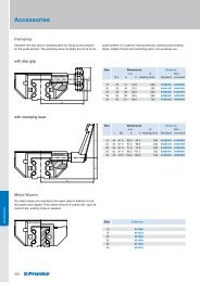
Clamping<br />
Cassette with star grip or clamping lever for fixing to any position<br />
on the guide section. The clamping does not apply any force to the<br />
with star grip<br />
with clamping lever<br />
Metal Wipers<br />
The metal wipers are inserted in the wiper plate in addition to the<br />
felt wipers and clipped. They assist removal of coarse dirt, such as<br />
metal chips, welding chips or sawdust.<br />
102<br />
guide system. It is used for manual devices, clamping and holding<br />
stops, infeed of tools and machining parts. Let us advise you.<br />
Size Dimensions Order no.<br />
mm Non-<br />
Ø a b h Holding force Standard corrosive<br />
15 25 41 19.0 200 84396AK 84396NK<br />
20 25 49 23.0 250 84441AK 84441NK<br />
25 32 56 28.0 250 84363AK 84363NK<br />
35 50 83 38.5 350 84364AK 84364NK<br />
45 63 101 48.0 750 84365AK 84365NK<br />
Size Dimensions Order no.<br />
mm Non-<br />
l Wt. b h Holding force Standard corrosive<br />
15 45 M 5 59.5 64.0 200 84396AH 84396NH<br />
20 45 M 5 67.5 68.0 250 84441AH 84441NH<br />
25 45 M 6 71.0 73.0 250 84363AH 84363NH<br />
35 63 M 8 96.0 101.5 350 84364AH 84364NH<br />
45 78 M10 116.0 126.0 750 84365AH 84365NH<br />
Size Order no.<br />
12 69126A<br />
15 69127A<br />
20 69128A<br />
25 69129A<br />
35 69130A<br />
45 69131A
Bellows<br />
The bellows for Aluminium Roller Guides protect the guide system<br />
from coarse dirt. They are available in any length. Fixing to the<br />
cassette and end plate is effected using glued Velcro ® . The<br />
Stop Screws<br />
The stop screws are screwed to the guide rails in thread (option).<br />
A fitted rubber cap cushions impact. The bore shape is delivered<br />
Caps<br />
The borings of the guide rails should be closed with plastic caps<br />
for best function of the wipers. These caps are included in every<br />
cassette wipers are not needed. Material: synthetic cloth with<br />
one-sided polyurethane coating, temperature: contact heat +80 °C,<br />
radiant heat +120 °C.<br />
Size Dimensions Order no.<br />
mm<br />
b h h1 k<br />
15 42 31.0 7.0 2.8 on request<br />
20 47 35.0 5.0 2.8<br />
25 55 42.5 6.5 2.8<br />
35 68 55.0 7.0 3.5<br />
45 87 67.0 7.0 3.5<br />
offset by a half bore jump for rail lengths with initial bore dimensions<br />
less than L11 min. Material: Chloroprene rubber (Cr), colour black.<br />
Size Dimensions Order no.<br />
mm<br />
d D K L11 min. P<br />
12 M 5 12 8 15.0 6.0 63504A<br />
15 M 5 12 8 16.0 6.0 63504A<br />
20 M 5 12 8 17.0 6.0 63504A<br />
25 M 6 15 10 20.5 7.5 63505A<br />
35 M 8 19 13 26.5 9.5 63506A<br />
45 M10 24 16 33.0 12.0 63507A<br />
delivery. They can also be ordered separately as replacements.<br />
Material: POM wear-resistant plastic, oil and ageing-resistant.<br />
Size Dimensions Order no.<br />
mm<br />
Cylinder screw DIN912 D<br />
12 M 3 6 87752A<br />
15 M 4 8 87753A<br />
20 M 5 10 87754A<br />
25 M 6 11 87755A<br />
35 M 8 15 87756A<br />
45 M10 18 87757A<br />
103<br />
Accessories
Accessories<br />
Accessories<br />
<strong>Linear</strong> Modules Type FTC/FTD<br />
Profile Fixings<br />
104<br />
Size Dimensions Order no.<br />
MAE R U AF DF DH DK DM DN DO DP DQ DR DT EF EM EN EQ RE<br />
mm<br />
15 M5 5.5 22 27 38 26 40 47.5 40 92 34.5 8 10 41.5 28.5 49 36 26 92981A<br />
20 M5 5.5 30 33 46 27 46 54.5 40 92 40.5 10 10 48.5 35.5 57 43 32 92982A<br />
25/35 M6 7.0 48 40 71 34 59 67.0 45 112 52.0 10 11 64.0 45.0 72 57 44 92983A<br />
Centre Supports<br />
E1 D1<br />
Size Dimensions Order no.<br />
mm<br />
R U UU AF DF DH DK DM DN DO DP DQ DR DS DT EF EM EN EQ RE<br />
E1<br />
15 M5 5.5 10 22 27 38 26 40 47.5 36 50 34.5 8 5.7 10 41.5 28.5 49 36 26 92821A<br />
20 M5 5.5 10 30 33 46 27 46 54.5 36 50 40.5 10 5.7 10 48.5 35.5 57 43 32 92826A<br />
25/35 M6 7.0 – 48 40 71 34 59 67.0 45 60 52.0 10 – 11 64.0 45.0 72 57 44 92831A<br />
D1<br />
15 M5 5.5 10 22 27 38 26 40 47.5 36 50 34.5 8 5.7 10 41.5 28.5 49 36 26 92820A<br />
20 M5 5.5 10 30 33 46 27 46 54.5 36 50 40.5 10 5.7 10 48.5 35.5 57 43 32 92825A<br />
25/35 M6 7.0 – 48 40 71 34 59 67.0 45 60 52.0 10 – 11 64.0 45.0 72 57 44 92830A
Cover Fixings<br />
Intermediate Drive Shaft<br />
End Switch<br />
Size Dimensions Order no.<br />
mm<br />
A1 E Ø U AB AC AD AE AF DG<br />
15 27 5.8 27 16 22 18 22 39 92810A<br />
20 36 6.6 36 18 26 20 30 50 92813A<br />
Size Dimensions Order no.<br />
Size Max. Dimensions Order no.<br />
torque<br />
mm<br />
C1 E Ø U AB AC AD AE AF AG DG<br />
15 27 6.6 52 16.0 25 25 22 – 91 92978A<br />
20 36 9.0 64 18.0 25 25 30 – 114 92979A<br />
25/35 70 9.0 48 12.5 30 30 48 128 174 92980A<br />
Nm mm<br />
DH Kb max. LD L R1 L ZR d R<br />
15 60 55 16 h7 5
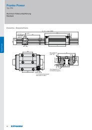
Technical Information<br />
Technical Information<br />
Type FD – <strong>Franke</strong> Dynamic<br />
1 Designs and System Description<br />
Aluminium Roller Guides from <strong>Franke</strong> are available as double<br />
rails with cassette or as a pair of single rails with a pair of roller<br />
shoes:<br />
Double rail with cassette (illustration 1):<br />
The double rail with cassette design is a <strong>Linear</strong> Guide<br />
ready-aligned as standard. Cassette and rail have standard<br />
connection borings.<br />
Illustration 1: Double Rail with Cassette<br />
Pair of single rails with pair of roller shoes (illustration 2):<br />
Single rails with roller shoes are part of the construction with<br />
the advantage of a variable guide width. The mating plate is<br />
specified by the customer.<br />
Illustration 2: Pair of Single Rails with Pair of Roller Shoes<br />
The cassette or the pair of roller shoes of standard type FDA<br />
run on 4 crosswise needle bearing rollers on rails of tough<br />
spring steel. Other types are available for individual cases with<br />
special requirements, e.g. non-corrosive rails or also customerspecific<br />
special designs.<br />
The Aluminium Roller Guides have lifetime lubrication. Traverse<br />
speeds of 10 m/s and accelerations of 40 m/s² can be realised.<br />
The operating temperature of the guides lies between –20 °C<br />
106<br />
and +100 °C. <strong>Franke</strong> is happy to advise when solutions are<br />
requested that are suitable for temperatures outside of this<br />
range.<br />
Cassettes mounted on rails are adjusted ex works free from<br />
clearance. It is possible to adjust the Aluminium Roller Guides<br />
to the individual load situation retrospectively using an integrated<br />
adjusting screw. The adjustment setting is best determined<br />
by measuring the slide resistance in the unloaded state (see<br />
illustration 3).<br />
Illustration 3: Measuring Slide Resistance<br />
The screwing of the cassette plate to the adjusting side is<br />
loosened slightly to adjust. Afterwards, the headless pin<br />
integrated in the cassette long side is readjusted. Turning the<br />
headless pin moves the roller shoe and, thus, increases or<br />
reduces the preload.<br />
The adjustment values for the individual types are shown in<br />
table 3.6 Slide Resistances. Further details on fitting and<br />
adjusting the guide are given in the instruction manual for<br />
the Aluminium Roller Guides.<br />
2 Dimensioning the Guides<br />
The following parameters are needed for correct dimensioning<br />
of the guide:<br />
• Selection of formation (see illustration 4)<br />
• All invasive or emerging forces / torques (dynamic / static)<br />
• Type of load (stationary, swelling, changing)<br />
• Environmental influences (e.g. temperature, moisture) or<br />
special operation conditions (e.g. clean room, vacuum)<br />
• Traverse speed and acceleration<br />
• Stroke length<br />
• Target lifetime in km<br />
All forces and torques must be within the permissible limits.<br />
The relevant data are on the pages for the types.
Illustration 4: Overview Formations<br />
Recommended safeties (for screw quality 8.8):<br />
• Pressure load: s > 1.2<br />
• Tension load: s > 2.5<br />
• Moment load: s > 4.0<br />
3 Notes for Mating Structure<br />
3.1 Mating Plate for Type FD<br />
A mating plate (continuing construction) must also be used<br />
when using single rails and roller shoes. The roller shoes and<br />
the mating plate together form the carriage.<br />
Note on layout of the mating plate of the carriage:<br />
the roller shoes have centering grooves for better alignment<br />
during assembly. You apply a centering bar to the mating plate<br />
for this purpose (illustration 5). The dimensions for producing<br />
the centering bar are in table 1. All other dimensions, tolerances<br />
and accuracies for the guides are given on the relevant pages<br />
of the catalogue.<br />
Illustration 5: Centering Shoulder<br />
Size a b<br />
mm mm<br />
12 4.5 9.6<br />
15 5.0 12.6<br />
20 7.5 16.1<br />
25 10.5 17.6<br />
35 12.5 26.1<br />
45 15.5 31.1<br />
Table 1: Dimensions Centering Bar<br />
3.2 Multi-Track Formations<br />
It is recommended to define a fixed and movable bearing site<br />
on the carriage plate for multi-track formations. This is the best<br />
way to equalise tolerances between the rails.<br />
For example, the movable bearing side can be designed with<br />
a carrier and a stroke safety. The fixed bearing side takes on the<br />
guide function, the movable bearing side equalises parallelism<br />
and height tolerances. It is recommended to locate the drive in<br />
direct proximity to the guide side, as the drive torque is taken<br />
from this.<br />
3.3 Mounting Surfaces<br />
Contact and support surfaces essentially determine the function<br />
and precision of the guide. Inaccuracies can be added for<br />
running accuracy of the guide system. For example, double-track<br />
formations require precise parallelism and height alignment. The<br />
accuracies for the mounting and contact surfaces of the guides<br />
from table 2 must be maintained to guarantee running accuracy<br />
of the guide:<br />
Size 12–20 25–45<br />
mm mm<br />
Max. tolerance for parallelism 0.03 0.05<br />
Max. evenness mounting surface 0.10 0.20<br />
Table 2: Accuracies Contact and Support Surfaces<br />
107<br />
Technical Information
Technical Information<br />
Technical Information<br />
3.4 Fixing the Rails<br />
Depending on the type of load the guide rails should either:<br />
1. be screwed<br />
2. be screwed and pinned<br />
3. be laid against a contact shoulder and screwed<br />
(illustration 6).<br />
Illustration 6: Fixing Rails<br />
The load capacity of the rails is influenced by the connections<br />
between the guide elements and the mating structure. Fixing to<br />
the mating structure is effected using screws of quality 8.8 with<br />
plain washers DIN 433.<br />
3.5 Fitting Instructions Coupled Rails<br />
Rails over a length of 4000 mm are coupled according to <strong>Franke</strong><br />
standards. Division according to <strong>Franke</strong> standards guarantees a<br />
universally even bore shape and optimum usage of the rail<br />
length. Divisions are also possible to customer specifications.<br />
Coupled rails are specially aligned with one another. Therefore,<br />
the rails have sequential numbering for the right fitting (e. g.<br />
A/1-1/1-2/2-2/E).<br />
Illustration 7: Coupled Rails /Auxiliary Cylinders<br />
108<br />
The rails are also marked with a groove on the rail underside,<br />
which must always be on the same side. The rails must be<br />
arranged free of play. The corresponding auxiliary cylinders<br />
(illustration 7) are used for this. The dimensions for the design<br />
of the auxiliary cylinders are in table 3. The cylinders are<br />
inserted at the joints of the rails in the raceway and preloaded<br />
using a device.<br />
Size Auxiliary Cylinder<br />
mm<br />
12 11<br />
15 11<br />
20 14<br />
25 16<br />
35 27<br />
45 35<br />
Table 3: Dimensions Auxiliary Cylinder<br />
The relevant tightening torques for the individual screws are<br />
given in table 4.<br />
Screws Tightening Torque<br />
M 3 1.1<br />
M 4 2.5<br />
M 5 5.0<br />
M 6 8.5<br />
M 8 21.0<br />
M10 41.0<br />
M12 71.0<br />
Table 4: Tightening Torques Screws<br />
3.6 Slide Resistances<br />
Size Slide Resistance<br />
N<br />
FDA FDB FDC FDD FDE FDG FDH<br />
12 Min. 0.2 0.2 0.5 – 0.5 0.6 –<br />
Max. 0.4 0.4 1.0 – 3.0 0.9 –<br />
15 Min. 0.5 0.5 0.5 – 1.0 0.5 –<br />
Max. 2.0 1.0 2.0 – 3.0 1.5 –<br />
20 Min. 1.0 0.5 1.0 – 1.0 1.0 –<br />
Max. 2.5 1.5 2.5 – 3.0 3.0 –<br />
25 Min. 1.5 0.5 1.5 1.5 1.5 0.5 2.5<br />
Max. 3.0 2.0 3.0 3.0 3.0 2.0 5.0<br />
35 Min. 2.0 1.0 2.0 – 2.0 1.0 4.0<br />
Max. 4.0 2.5 4.0 – 4.0 2.5 7.0<br />
45 Min. 2.5 2.0 3.5 – 2.5 2.0 5.0<br />
Max. 5.0 4.0 10.5 – 5.0 4.0 8.0
3.7 Running Accuracy and Stiffness<br />
µm<br />
100<br />
90<br />
80<br />
70<br />
60<br />
50<br />
40<br />
30<br />
20<br />
10<br />
0<br />
Degree<br />
1.0<br />
0.9<br />
0.8<br />
0.7<br />
0.6<br />
0.5<br />
0.4<br />
0.3<br />
0.2<br />
0.1<br />
0<br />
Degree<br />
12<br />
20<br />
15<br />
<strong>Franke</strong> Dynamic running accuracy over 1 m<br />
FDB, FDG<br />
FDA, FDC,<br />
FDD, FDE<br />
FDH<br />
12 15 20 25 35 45 Size<br />
25<br />
Stiffness on the X-axis: FDA, FDC, FDD, FDE, FDH<br />
35<br />
100 200 300 400 500 600 700 800 Nm<br />
45<br />
Stiffness on the X-axis: FDB, FDG<br />
0.150<br />
0.135<br />
0.120<br />
35<br />
0.105 25<br />
0.090<br />
20<br />
15<br />
0.075<br />
0.060<br />
12<br />
0.045<br />
0.030<br />
0.015<br />
45<br />
0<br />
10 20 30 40 50 60 70 80 Nm<br />
Type FP – <strong>Franke</strong> Power<br />
1 Designs and System Description<br />
<strong>Franke</strong> <strong>Linear</strong> Guides of the type FPA comprise double rails<br />
with cassette (see illustration 1). The cassette has integrated<br />
recirculating rollers for high load ratings and stiffness. The rails<br />
of the type FPA are interchangeable with the rails of the <strong>Franke</strong><br />
Aluminium Roller Guide.<br />
Illustration 1: Recirculating Roller Guide<br />
<strong>Franke</strong> Recirculating Roller Guides are available in one preload<br />
class. Traverse speeds of 3 m/s and accelerations of 30 m/s²<br />
are possible. The operating temperature of the guides lies<br />
between –20 °C and +80 °C.<br />
2 Dimensioning the Guides<br />
The following parameters are needed for correct dimensioning<br />
of the guide:<br />
• Selection of formation (see illustration 2)<br />
• All invasive or emerging forces / torques (dynamic / static)<br />
• Type of load (stationary, swelling, changing)<br />
• Environmental influences (e.g. temperature, moisture) or<br />
special operating conditions (e.g. clean room, vacuum)<br />
• Traverse speed and acceleration<br />
• Stroke length<br />
• Target lifetime in km<br />
Illustration 2: Overview Formations<br />
109<br />
Technical Information
Technical Information<br />
Technical Information<br />
All forces and torques must be within the permissible limits.<br />
The relevant data are on the pages for the individual types.<br />
Recommended safeties (for screw quality 8.8):<br />
• Pressure load: s > 1.2<br />
• Tension load: s > 2.5<br />
• Moment load: s > 4.0<br />
Calculations can be performed by <strong>Franke</strong>.<br />
3 Notes for Mating Structure<br />
3.1 Multi-Track Formations<br />
It is recommended to define a fixed and movable bearing site<br />
on the carriage plate for multi-track formations. This is the best<br />
way to equalise tolerances between the rails.<br />
For example, the movable bearing side can be designed with<br />
a carrier and a stroke safety. The fixed bearing side takes on the<br />
guide function, the movable bearing side equalises parallelism<br />
and height tolerances. It is recommended to locate the drive in<br />
direct proximity to the guide side, as the drive torque is taken<br />
from this.<br />
3.2 Mounting Surfaces<br />
Contact and support surfaces essentially determine the function<br />
and precision of the guide. Inaccuracies can be added for<br />
running accuracy of the guide system. For example, double-track<br />
formations require precise parallelism and height alignment. The<br />
accuracies for the mounting and contact surfaces of the guides<br />
from table 1 must be maintained to guarantee running accuracy<br />
of the guide:<br />
Size 25<br />
110<br />
mm<br />
Max. tolerance for parallelism 0.05<br />
Max. evenness mounting surface 0.20<br />
Table 1: Accuracies Bearing and Contact Surfaces<br />
All other dimensions, tolerances and accuracies for the guides<br />
are given on the relevant pages of the catalogue.<br />
3.3 Fixing the Rails<br />
Depending on the type of load the guide rails should either:<br />
1. be screwed<br />
2. be screwed and pinned<br />
3. be laid against a contact shoulder and screwed<br />
(illustration 3).<br />
Illustration 3: Fixing Rails<br />
The load capacity of the rails is influenced by the connections<br />
between the guide elements and the mating structure. Fixing to<br />
the mating structure is effected using screws of quality 8.8 with<br />
plain washers DIN 433.<br />
3.4 Fitting Instructions Coupled Rails<br />
Rails over a length of 4000 mm are coupled according to <strong>Franke</strong><br />
standards. Division according to <strong>Franke</strong> standards guarantees<br />
a universally even bore shape and optimum usage of the rail<br />
length. Divisions are also possible to customer specifications.<br />
Coupled rails are specially aligned with one another. Therefore,<br />
the rails have sequential production numbering for the right<br />
fitting (e.g. A/1-1/1-2/2-2/E).<br />
The rails are also marked with a groove on the rail underside,<br />
which must always be on the same side. The rails must be<br />
arranged free of play. The corresponding auxiliary cylinders<br />
(illustration 4) are used for this. The dimensions for the design<br />
of the auxiliary cylinders are in table 2. The cylinders are<br />
inserted at the joints of the rails in the raceway and preloaded<br />
using a device.
Illustration 4: Coupled Rails /Auxiliary Cylinders<br />
Size Auxiliary Cylinder<br />
mm<br />
25 16<br />
Table 2: Dimensions Auxiliary Cylinder<br />
The relevant tightening torques for the individual screws are<br />
given in table 3.<br />
Screws Tightening Torque<br />
M6 8.5<br />
M8 21.0<br />
Table 3: Tightening Torques Screws<br />
4 Lubrication<br />
The Recirculating Roller Guides are initially lubricated ex works.<br />
After approx. 2000 km of running performance, the guides must<br />
be relubricated with 1 to 2 grams of lubricant.<br />
5 Slide Resistances<br />
Size Slide resistance<br />
N<br />
FP<br />
25 Min. 17.5<br />
Max. 30.0<br />
6 Running Accuracy and Stiffness<br />
µm<br />
50<br />
45<br />
40<br />
35<br />
30<br />
25<br />
20<br />
15<br />
10<br />
5<br />
0<br />
Degree<br />
1.0<br />
0.9<br />
0.8<br />
0.7<br />
0.6<br />
0.5<br />
0.4<br />
0.3<br />
0.2<br />
0.1<br />
0<br />
<strong>Franke</strong> Power running accuracy over 1 m<br />
FP<br />
12 15 20 25 35 45 Size<br />
Stiffness <strong>Franke</strong> Power<br />
Size 25 by the X-axis<br />
Size 25 by the Y/Z-axis<br />
40 80 120 160 200 240 280 Nm<br />
111<br />
Technical Information
Technical Information<br />
Technical Information<br />
Type FR – <strong>Franke</strong> Robust<br />
1 Designs and System Description<br />
Aluminium Recirculating Ball Guides of type FRA comprise two<br />
individual rails and recirculating elements (see illustration 1).<br />
The recirculating elements are mounted on the mating plate and<br />
together form the carriage. The construction of the mating plate<br />
is specified by the customer.<br />
Illustration 1: Aluminium Recirculating Ball Guide<br />
Guides of the type FRA are particularly robust and have<br />
high load capacity. The max. traverse speed is 3 m/s, the<br />
max. acceleration is 30 m/s². Use is possible in a temperature<br />
range of –10 °C to +80 °C.<br />
The slide resistance can be adjusted for <strong>Linear</strong> Guides of<br />
the type FRA. The fixing screws on the slider plate on the<br />
adjustment side must be loosened. Using an optional tool the<br />
recirculating element can be moved towards the carriage plate<br />
and the adjustment is altered. The adjustment setting is best<br />
determined by measuring the slide resistance in the unloaded<br />
state.<br />
The adjustment values are shown in table 5 Slide Resistances.<br />
Further details on fitting and adjusting the guide are given in<br />
the instruction manual for the Aluminium Recirculating Ball<br />
Guides.<br />
2 Dimensioning the Guides<br />
The following parameters are needed for correct dimensioning<br />
of the guide:<br />
• Selection of formation (see illustration 2)<br />
• All invasive or emerging forces / torques (dynamic / static)<br />
• Type of load (stationary, swelling, changing)<br />
• Environmental influences (e.g. temperature, moisture) or<br />
special operating conditions (e.g. clean room, vacuum)<br />
• Traverse speed and acceleration<br />
• Stroke length<br />
• Target lifetime in km<br />
112<br />
Illustration 2: Overview Formations<br />
All forces and torques must be within the permissible limits.<br />
The relevant data are on the pages for the individual types.<br />
Recommended safeties (for screw quality 8.8):<br />
• Pressure load: s > 1.2<br />
• Tension load: s > 2.5<br />
• Moment load: s > 4.0<br />
Calculations can be performed by <strong>Franke</strong>.<br />
3 Notes for Mating Structure<br />
3.1 Mounting Surfaces<br />
Contact and support surfaces essentially determine the function<br />
and precision of the guide. Inaccuracies can be added for<br />
running accuracy of the guide system. Therefore, the linearity<br />
and parallelism of the mating structure must be considered.<br />
The maximum permissible deviation across the whole stroke is<br />
0.04 mm.<br />
3.2 Fixing the Rails<br />
The rails are fixed against a bearing shoulder and screwed (see<br />
illustration 3). The two guide rails must be fitted parallel to one<br />
another. This is how you control the linearity and parallelism of<br />
the rails. The maximum total error must be less than 0.06 mm.<br />
Illustration 3: Fixing Rails
The load capacity of the rails is influenced by the connections<br />
between the guide elements and the mating structure. Fixing to<br />
the mating structure is effected using screws of quality 8.8 with<br />
plain washers DIN 433.<br />
Note: the raceways of the type FRA 08-13 can be exchanged in<br />
the event of wear. A rail’s raceways must always be completely<br />
exchanged. The new raceways are ordered according to the<br />
original order or the item number of the rail.<br />
3.3 Fitting Instructions Coupled Rails<br />
Rails over a length of 4000 mm are coupled according to <strong>Franke</strong><br />
standards. Division according to <strong>Franke</strong> standards guarantees<br />
a universally even bore shape and optimum usage of the rail<br />
length. Divisions are also possible to customer specifications.<br />
Coupled rails are specially aligned with one another. Therefore,<br />
the rails have sequential production numbering for the right<br />
fitting (e.g. A/1-1/1-2/2-2/E). The top side of the rails is<br />
consistently marked with a bevel.<br />
The rails must be evenly aligned during fitting. There must be<br />
a fitting gap between the rails. The rails should be fitted at a<br />
temperature of approx. 20 °C. The screw tightening torques<br />
from table 1 apply in this instance:<br />
Screw Tightening Torque<br />
M 5 6.0<br />
M 6 10.0<br />
M 8 25.0<br />
M 10 49.0<br />
Table 1: Tightening Torques Screws FRA<br />
There are more detailed instructions on fitting the rails in the<br />
instruction manual for <strong>Franke</strong> <strong>Linear</strong> Guides with Recirculating<br />
Balls.<br />
4 Lubrication<br />
The Aluminium Recirculating Ball Guides must always be coated<br />
with a film of lubricant. The system needs to be lubricated every<br />
500 to 700 operating hours or 1 to 2 times a year.<br />
Recirculating elements are connected to central lubrication as<br />
standard. This provides relubrication via the boring on the<br />
mounting surface.<br />
5 Slide Resistances<br />
Size Slide Resistance per Pair of Recirculating Elements<br />
N<br />
FR<br />
6 35 – 45<br />
8 60– 80<br />
10 90– 120<br />
13 150– 200<br />
6 Running Accuracy<br />
µm<br />
100<br />
90<br />
80<br />
70<br />
60<br />
50<br />
40<br />
30<br />
20<br />
10<br />
0<br />
<strong>Franke</strong> Robust running accuracy over 1 m<br />
FR<br />
6 8 10 13 Size<br />
113<br />
Technical Information
Technical Information<br />
Technical Information<br />
<strong>Linear</strong> Tables/Modules<br />
1 Design<br />
<strong>Franke</strong> <strong>Linear</strong> <strong>Systems</strong> are suitable for example for automation<br />
tasks in measuring and testing processes or for rationalisation<br />
in the handling and fitting sector. The selection ranges from<br />
strokes from 100 mm to 7000 mm, drive is effected via a spindle<br />
or belt drive. The light aluminium construction combined with<br />
the integrated <strong>Franke</strong> guide system allows high load ratings and<br />
torque loads. Precise technical details are on the relevant pages<br />
in the catalogue.<br />
2 Area of Use<br />
We recommend use of <strong>Franke</strong> <strong>Linear</strong> <strong>Systems</strong> with safety s ≥ 3<br />
for simple loads or acceleration and moment loads. A safety of<br />
s ≥ 6 should be used for dynamic torques. You can choose any<br />
installation position. We recommend a bedstop or a brake for<br />
vertical operation.<br />
The position accuracy of the type FTB <strong>Linear</strong> <strong>Systems</strong> is<br />
±0.025/300mm (IT7) in accordance with the spindle stiffness<br />
accuracy. Other accuracies are possible on request. The<br />
repeat accuracy is ≤ 0.01mm. The run accuracy of the FTB<br />
<strong>Linear</strong> Tables is 0.02/300 mm. <strong>Franke</strong> <strong>Linear</strong> Tables can be<br />
used in a temperature range of –20 °C to +80 °C. The FTD<br />
15 – 35 <strong>Linear</strong> <strong>Systems</strong> are suitable for permanent operation<br />
at temperatures of –30 °C to +80 °C. Please contact us<br />
concerning use in other temperature ranges.<br />
3 End Switches and Reference Points<br />
• Reference switches, measuring systems: <strong>Franke</strong> <strong>Linear</strong><br />
<strong>Systems</strong> of type FTB have inductive proximity switches,<br />
which are set to the final stroke position. A further proximity<br />
switch can be provided as a reference switch is desired. With<br />
the type FTC and FTD <strong>Linear</strong> Modules there is the possibility<br />
of attaching a freely adjustable end switch to the outside.<br />
<strong>Franke</strong> <strong>Linear</strong> <strong>Systems</strong> are equipped with inductive end and<br />
reference switches PNP-nc 10-30VDC as standard. PNP-no,<br />
NPN-no and NPN-nc switches are available on request. The<br />
addition or integration of a length measuring system with<br />
sinus or square wave signal is possible on request. Shaft<br />
encoders can be mounted on the motor.<br />
• Multi-axle units: <strong>Franke</strong> <strong>Linear</strong> <strong>Systems</strong> can be combined<br />
to form multi-axle units. The necessary angles and adaptor<br />
plates are selected according to your needs. We supply<br />
completely fitted units, ready cabled and aligned, with other<br />
accessories on request.<br />
• Motorisation: An array of step or servo motors can be<br />
connected to the <strong>Linear</strong> <strong>Systems</strong>. Connection flanges and<br />
couplings are modified accordingly. The customer’s own<br />
motors can also be considered.<br />
114<br />
• Motor Redirection, Gears: the motor is mounted in the<br />
extension of the stroke axle as standard. For special<br />
applications, e.g. in limited space, a motor redirection can be<br />
integrated on request using a toothed belt or reversing gears.<br />
Please call us.<br />
4 Maintenance and Lubrication<br />
<strong>Franke</strong> <strong>Linear</strong> <strong>Systems</strong> are low-maintenance and have lifetime<br />
lubrication ex works. No relubrication is required up to the ball<br />
screw. In the event of grease escaping through the spindle<br />
wave, relubrication – depending on the individual case – is<br />
required. We recommend relubrication at intervals of approx.<br />
700 working hours with approx. 1–2 g grease. If necessary<br />
clean the inner areas and the guide tracks and coat these with<br />
grease.<br />
Fully synthetic lubricants are preferred for long-term lubrication.<br />
<strong>Franke</strong> uses the fully synthetic special lubricant ISOFLEX<br />
TOPAS NCA52 at the factory (manuf. Klüber). We recommend<br />
high-quality lithium-saponificate grease based on mineral oil.<br />
When mixing lubricants, the compatibility of the variants must<br />
be considered with regard to type of base oil, thickening agent,<br />
base oil viscosity and NLGI class. For extreme conditions<br />
or extraordinary operating conditions (vacuum, radiation,<br />
high temperature), you should speak to us or the lubricant<br />
manufacturer.<br />
5 Definitions<br />
• The running accuracy is the greatest possible deviation of<br />
any one place on the moved table surface from the ideal<br />
straight lines when the entire stroke track passes (subject<br />
to the unevenness of the subconstruction).<br />
• The position accuracy is the greatest possible deviation from<br />
the achievement of a preselected point, which is passed from<br />
a predefined point of origin.<br />
• The repeat accuracy is the greatest possible deviation<br />
from the multiple achievement of a preselected point. The<br />
measuring system used is crucial for the level of accuracy.<br />
• The resolution is the smallest possible traverse path. It<br />
depends on the spindle pitch, the ratio, the step angle and<br />
the classification of the measuring system. Errors in the<br />
positioning or repeat can be neutralised using the resolution.<br />
Therefore, it should always be greater than the deviation from<br />
the permissible position accuracy.<br />
Please follow assembly and maintenance instructions.<br />
They are included with every delivery.
Notes<br />
115<br />
Technical Information
Your Partners.<br />
Presenting the <strong>Franke</strong> Team.<br />
Taking care of customers from A to Z competently and reliably – that is the declared <strong>Franke</strong><br />
target. Whether further information on the products, specific offers, technical sales on<br />
site, training or support on maintenance – our staff are gladly there for you for all queries<br />
concerning <strong>Antifriction</strong> <strong>Bearings</strong> and <strong>Linear</strong> <strong>Systems</strong>.<br />
116<br />
Management<br />
(from the left)<br />
Daniel Groz Managing Director<br />
Sascha Eberhard Managing Director<br />
Jörg Egelhaaf Technical Manager<br />
Harald Müller Production Manager<br />
Günter Fischer Sales Manager<br />
Oliver Schröder Purchasing Manager
Reception<br />
Sales, Shipping, Logistics<br />
(from the left)<br />
Brigitte Wild, Manuela Neher<br />
Tel. +49 7361 920-0 info@franke-gmbh.de<br />
(from the left)<br />
Alexandra Stoll Tel. +49 7361 920-112 a.stoll@franke-gmbh.de<br />
Petra Abele Tel. +49 7361 920-121 p.abele@franke-gmbh.de<br />
Heike Faustmann Tel. +49 7361 920-122 h.faustmann@franke-gmbh.de<br />
Michael Momesso Tel. +49 7361 920-118 m.momesso@franke-gmbh.de<br />
Christiane Schiele Tel. +49 7361 920-117 c.schiele@franke-gmbh.de<br />
Marlen Maier Tel. +49 7361 920-123 m.maier@franke-gmbh.de<br />
117
Technical Sales<br />
(from the left)<br />
Thilo Deutsch Tel. +49 7361 920-113 t.deutsch@franke-gmbh.de<br />
Markus Wagner Tel. +49 7361 920-185 m.wagner@franke-gmbh.de<br />
Stephan Kuhn Tel. +49 7361 920-180 s.kuhn@franke-gmbh.de<br />
118<br />
Internet<br />
Training<br />
We offer maintenance training for <strong>Antifriction</strong> <strong>Bearings</strong> and<br />
<strong>Linear</strong> <strong>Systems</strong> free of charge. Dates can be agreed individually.<br />
Training takes place either at out facilities in Aalen or directly<br />
at your site.<br />
CAD data for download, practical examples, news on our company,<br />
industry brochures and and and – a look at www.franke-gmbh.com<br />
is worthwhile.<br />
Maintenance<br />
Our experts perform the maintenance and adjustment<br />
of <strong>Antifriction</strong> <strong>Bearings</strong> and <strong>Linear</strong> <strong>Systems</strong> onsite.<br />
There are also Maintenance aids and instruction<br />
manuals to assist you.
<strong>Franke</strong> Worldwide<br />
Germany<br />
Technisches Büro Tober<br />
Langenberger Straße 21 H<br />
09337 Callenberg<br />
Tel. +49 3723 6686-87<br />
Fax +49 3723 6686-89<br />
Mobile +49 172 7326532<br />
franke@tober-gmbh.de<br />
Ing. Michael Topf<br />
Rheinstraße 7<br />
15732 Eichwalde<br />
Tel. +49 30 67539783<br />
Fax +49 30 67539784<br />
Mobile +49 172 3064469<br />
michael.topf@t-online.de<br />
an-tec<br />
Mechanische Antriebstechnik<br />
Kristian Pölk<br />
Leonard-Nelson-Straße 32<br />
37073 Göttingen<br />
Tel. +49 551 48967-35<br />
Fax +49 551 48967-34<br />
k.poelk@an-tec.de<br />
Günter Horl <strong>GmbH</strong><br />
Zwingenbergstraße 287<br />
47800 Krefeld<br />
Tel. +49 2151 598550<br />
Fax +49 2151 502963<br />
Mobile +49 172 2779089<br />
info@horl-gmbh.de<br />
Ingenieurbüro Lothar Meyer<br />
Pfalzstraße 5<br />
65329 Hohenstein<br />
Tel. +49 6128 450080<br />
Fax +49 6128 450079<br />
Mobile +49 172 8284128<br />
lotharmeyer@web.de<br />
Janotec Handelsvertretung<br />
Joachim Janot<br />
Gutenbergstraße 13<br />
73430 Aalen<br />
Tel. +49 7361 680660<br />
Fax +49 7361 680662<br />
Mobile +49 172 7396071<br />
janot@janotec.de<br />
Christian Burghard<br />
Obere Bahnstraße 64<br />
73431 Aalen<br />
Tel. +49 7361 920-124<br />
Fax +49 7361 920-120<br />
Mobile +49 173 3234833<br />
c.burghard@franke-gmbh.de<br />
Volker Schmerreim <strong>GmbH</strong><br />
Dorfweg 12 Hemhof<br />
83093 Bad Endorf<br />
Tel. +49 8053 9058<br />
Fax +49 8053 3593<br />
Mobile +49 170 5227791<br />
info@schmerreim.de<br />
Europe<br />
Austria<br />
René Schuber (ZIP 1, 2, 6, 7, 8, 9)<br />
Hardeggasse 67/29/3<br />
1220 Wien<br />
Tel. +43 1 2838742<br />
Fax +43 1 2838742<br />
Mobile +43 676 7079221<br />
office@hv-schuber.at<br />
Gerhard Bell (ZIP 3, 4, 5)<br />
Billrothstraße 32<br />
4050 Traun<br />
Tel. +43 6644227912<br />
Fax +43 7229 75546<br />
gerhard.bell@utanet.at<br />
Czech Republic<br />
Betz S.R.O.<br />
Zeyerova 6/234<br />
35301 Mariànskè Làznè<br />
Tel. +420 354 620095<br />
Fax +420 354 627307<br />
miloslav.strnad@betz.cz<br />
France<br />
Agora Technique<br />
8 Bis Rue Volta, Parc Volta<br />
94140 Alfortville<br />
Tel. +33 1 45184370<br />
Fax +33 1 45184371<br />
benitah.agora@wanadoo.fr<br />
Great Britain<br />
<strong>Antifriction</strong> <strong>Bearings</strong><br />
<strong>Franke</strong> <strong>Bearings</strong> Ltd.<br />
Unit 5/90, Berry Lane<br />
Longridge, PR3 3WH<br />
Tel. +44 1772 723777<br />
Fax +44 1772 733777<br />
sales@linearmotionsystems.co.uk<br />
<strong>Linear</strong> <strong>Systems</strong><br />
LMS <strong>Linear</strong> Motion <strong>Systems</strong> Ltd.<br />
Unit 5/90, Berry Lane<br />
Longridge, PR3 3WH<br />
Tel. +44 1772 723777<br />
Fax +44 1772 733777<br />
sales@linearmotionsystems.co.uk<br />
Hungary<br />
Somogyi Kft.<br />
Temetöi üzletsor<br />
2510 Dorog<br />
Tel. +36 33 522-222<br />
Fax +36 33 522-220<br />
Mobile +36 30 6309456<br />
poloskei@skft.hu<br />
Italy<br />
HTC Srl<br />
Via XXIV Maggio 40<br />
10082 Cuorgnè TO<br />
Tel. +39 0124 651916<br />
Fax +39 0124 690205<br />
info@htcfranke.it
Netherlands/Belgium<br />
Gileon Technical Components<br />
Eindsestraat 129A<br />
5105 NA Dongen (Netherlands)<br />
Tel. +31 85 2017 814<br />
Fax +31 84 8399 240<br />
Mobile +31 627 046413<br />
info@gileon.nl<br />
Poland<br />
JORDAN matcon Sp. z o.o.<br />
Kijewo 50<br />
63-000 Sroda Wlkp.<br />
Tel. +48 61 286 07 01<br />
Fax +48 61 286 07 05<br />
info@jordan-matcon.pl<br />
Portugal<br />
Iberacero S.L.<br />
Zona Industrial Maia I, Sector I, Lote 45<br />
4475-132 Gemunde<br />
Tel. +351 22 947 9020<br />
Fax +351 22 947 9029<br />
geral@iberacero.com<br />
Spain<br />
Vorkauf Sociedad Anonima<br />
Avda. Comandante Franco, 3<br />
28016 Madrid<br />
Tel. +34 91 3591712<br />
Fax +34 91 3500431<br />
vorkauf@vorkauf.es<br />
ASP Automatic System Partners<br />
Pol. Ind. El Nogal<br />
C/ El Nogal 8<br />
28110 Algete, Madrid<br />
Tel. +34 916 20 900<br />
Fax +34 916 282 554<br />
info@asp-es.com<br />
Sweden/Denmark<br />
Bengtssons Maskin AB<br />
Företagsvägen 14<br />
Box 501<br />
23224 Arlöv (Sweden)<br />
Tel. +46 40 6807309<br />
Fax +46 40 430271<br />
peter.knutsson@<br />
bengtssons-maskin.se<br />
Switzerland<br />
Emil Vögelin AG<br />
Rinaustrasse 476<br />
4303 Kaiseraugst<br />
Tel. +41 61 8169016<br />
Fax +41 61 8169000<br />
cgs@voegelinag.ch<br />
Turkey<br />
HPA Teknoloji Gelistirme Ltd. Sti.<br />
1201/1 Sok. No: 4/A P-21<br />
Temsil Plaza<br />
Yenisehir/Izmir<br />
Tel. +90 232 469 7961<br />
Fax +90 232 433 9625<br />
info@hpa.com.tr<br />
America<br />
Canada<br />
<strong>Franke</strong> Canada<br />
61 Chateau Crescent<br />
N3H5S2 Cambridge,<br />
Ontario<br />
Tel. +1 519 591 3257<br />
Fax +1 519 650 8123<br />
info@franke-ca.com<br />
USA<br />
<strong>Antifriction</strong> <strong>Bearings</strong><br />
Rotek Incorporated<br />
1400 South Chillicothe Rd.<br />
P.O. Box 312<br />
Aurora, Ohio 44202<br />
Tel. +1 330 5624000<br />
Fax +1 330 5629351<br />
sales@rotek-inc.com<br />
<strong>Linear</strong> <strong>Systems</strong><br />
Parker Origa Corporated<br />
100 West Lake Drive<br />
Glendale Heights, IL 60139<br />
Aurora, Ohio 44202<br />
Tel. +1 630 871-8300<br />
Fax +1 630 871-1515<br />
cathy.lascero@parker.com<br />
Middle East<br />
Israel<br />
American Aviation Ltd.<br />
Keidar Center, 19 HaHaroshet Street<br />
Industrial Zone<br />
Ra‘anana 43101<br />
Tel. +972 9 7487826<br />
Fax +972 9 7487830<br />
yoav@amav.co.il<br />
Asia<br />
China<br />
Sinotech Asia Ltd.<br />
Unit 1501-02A, Tower 5,<br />
China Hong Kong City,<br />
33 Canton Road, Kowloon<br />
Hong Kong<br />
Tel. +852 2199 4600<br />
Fax +852 2369 0796<br />
manfred.baeuerle@<br />
groz-beckert.com<br />
India<br />
Neel Kamal<br />
55, 1st Floor S.V. Complex,<br />
K.R. Road, Basavanagudi<br />
560 004 Bangalore<br />
Tel. +91 802 662 0402<br />
Fax +91 802 662 0400<br />
megamaintenance@vsnl.com<br />
Korea<br />
Numacs Co. Ltd.<br />
202-602 Bucheon<br />
Techno Park 2-danji<br />
Yakdae-dong Wonmi-gu,<br />
Bucheon-si Gyeonggi-do<br />
420-733, South Korea<br />
Tel. +82 324618110<br />
Fax +82 324618112<br />
info@numacs.co.kr<br />
Taiwan<br />
Groz-Beckert (Taiwan) Ltd.<br />
5F No. 202, Sec.2 Yanping N.Rd.<br />
Datong District, Taipei City 103<br />
Tel. +886 2 25531608<br />
Fax +886 2 25531627<br />
gary.shih@groz-beckert.com
We keep processes moving.<br />
All over the world.
Medical technology computer tomography medical supplies<br />
examination tables operating tables x-rays textile industry<br />
circular knitting machines flat knitting machines knitting<br />
machines mechanical engineering industry rotary tables<br />
tool changers welding plants laser cutting stone saws<br />
robotic pick and place portal robots transfer systems<br />
handling systems bending arm robots clean room wafer<br />
steppers chip production satellite technology food<br />
industry racks agitators cheese production packaging<br />
industry lifting gear film packaging reeling machines<br />
mattress packaging optics laser positioning glasses<br />
production<br />
<strong>Franke</strong> <strong>GmbH</strong><br />
reserved.<br />
Obere Bahnstraße 64<br />
rights<br />
73431 Aalen, Germany<br />
All<br />
Tel. +49 7361 920-0<br />
Fax +49 7361 920-120<br />
info@franke-gmbh.de<br />
www.franke-gmbh.com GK_e_01/2010<br />
Certified in accordance with<br />
ISO 9001:2000<br />
ISO 14001:2004