TRIANGULATION LASER SENSORS, LDS603 Series Rev. G (26.06 ...
TRIANGULATION LASER SENSORS, LDS603 Series Rev. G (26.06 ...
TRIANGULATION LASER SENSORS, LDS603 Series Rev. G (26.06 ...

You also want an ePaper? Increase the reach of your titles
YUMPU automatically turns print PDFs into web optimized ePapers that Google loves.
<strong>TRIANGULATION</strong> <strong>LASER</strong> <strong>SENSORS</strong>, <strong>LDS603</strong> <strong>Series</strong><br />
1. GENERAL INFORMATION<br />
The sensors are intended for non-contact measuring and checking of position, displacement,<br />
dimensions, surface profile, deformation, vibrations, sorting and sensing of technological objects as<br />
well as for measuring levels of liquid and bulk materials.<br />
The series includes 24 sensors with the measurement range, from 2 to 1000 mm and the base<br />
distance from 10 to 245 mm. Custom-ordered configurations are possible with parameters different<br />
from those shown below.<br />
Page 1/22<br />
2. BASIC TECHNICAL DATA AND PERFORMANCE CHARACTERISTICS<br />
<strong>LDS603</strong> X/2 X/5 X/10 X/15 X/25 X/30 X/50 X/10 X/250 X/500 X/750 X/1000<br />
Base distance, X, mm 10 15<br />
<strong>Rev</strong>. G (<strong>26.06</strong>.2008)<br />
15, 25<br />
55<br />
15, 30<br />
60<br />
25, 45<br />
80<br />
35, 55<br />
95<br />
45, 65<br />
105<br />
60, 90<br />
140<br />
80 125 145 245<br />
Working range, mm 2 5 10 15 25 30 50 100 250 500 750 1000<br />
Linearity, % ±0,1of the range ±0,2…0,3<br />
Resolution, % 0.01 of the range 0,03<br />
Maximum sampling rate, kHz 2 or 5 or 8<br />
Laser type 1…3 mW, wavelength 660 nm 5mW, 660 nm<br />
digital<br />
Output signal<br />
RS232 (460,8 kbit/s max) or RS485 (460,8 kbit/s max) or RS232 and CAN V2.0B<br />
(1 Mbit/s)<br />
analog 4…20 mА (≤500 Ω load) or 0…10 V<br />
Synchronization input 2,4-5 V (CMOS, TTL)<br />
Power Supply, V 5 (4,5…9) or 12 (9…18) or 24 (18…36)<br />
Alarm output NPN: 100 mA max; 40 V max<br />
Power consumption, W 1,5…2<br />
Enclosure rating IP67<br />
Operating temperature, °С<br />
-10…+60, (-30…+60 for the sensor with built-in heater),<br />
(-30…+120 for the sensors with cooling housing)<br />
Weight (without cable), g 100<br />
Note: All specifications apply for a diffusely reflecting white paper<br />
3. EXAMPLE OF ITEM DESIGNATION WHEN ORDERING<br />
<strong>LDS603</strong>.F-X/L-SERIAL-OUT-IN-AL-VV-CC-M-H-P<br />
Symbol Description<br />
F maximum sampling rate , kHz (2 or 5 or 8)<br />
X base distance (beginning of the range) in mm<br />
L operating range in mm<br />
SERIAL type of the serial interface (RS232 or RS485 or RS232&CAN)<br />
OUT attribute showing the presence of Current Loop (I) or U output<br />
Note: only for the sensors with RS232 or RS485<br />
IN trigger input (input of synchronization)<br />
AL<br />
This signal is of dual purpose. It can be used as:<br />
1) logical output; ("0" – object is beyond the range (beyond the selected window in the range), "1"<br />
– object is within the range (within the selected window in the range))<br />
2) line of mutual synchronization for two and more sensors<br />
VV supply voltage<br />
CC Cable gland – CG or socket + cable - CC (Binder 702, IP67, )<br />
M Cable length in m<br />
H Sensor with built-in heater<br />
P Sensor with protect air cooling housing (See annex # 1)<br />
Finger GmbH & Co. KG • Schamerloh 84 • 31606 Warmsen • Internet: www.finger-kg.de • email: info@finger-kg.de
<strong>TRIANGULATION</strong> <strong>LASER</strong> <strong>SENSORS</strong>, <strong>LDS603</strong> <strong>Series</strong><br />
For example: <strong>LDS603</strong>.5-80/25-232-I-12-CC-3 – 5 kHz max frequency, base distance – 80 mm, range – 25 mm, serial<br />
port - RS232, 4…20 mA output available, supply voltage 12V (9…18V), socket + cable, 3 m.<br />
4. STRUCTURE AND OPERATING PRICIPLE<br />
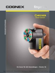
Operation of the sensors is based on the principle of optical triangulation (Figure 1.)<br />
Radiation of a semiconductor laser 1 is focused by a lens 2 onto an object 6. Radiation reflected by<br />
the object is collected by a lens 3 onto a linear CMOS array 4. A signal processor 5 calculates the<br />
distance to the object from the position of the light spot on the array 4.<br />
Page 2/22<br />
<strong>Rev</strong>. G (<strong>26.06</strong>.2008)<br />
BASE DISTANCE WORKING RANGE<br />
Figure 1.<br />
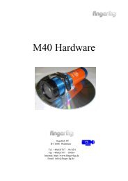
5. OVERALL AND MOUNTING DIMENSIONS<br />
5.1. Overall and mounting dimensions of the 10/2 sensor are shown in Figure 2 and the others –<br />
in Figure 3. Sensor package is made of anodized aluminum. The front panel of the package has two<br />
windows: one is output, the other for receiving radiation reflected from the object under control.<br />
The package also contains mounting holes.<br />
Figure 2. Figure 3.<br />
Finger GmbH & Co. KG • Schamerloh 84 • 31606 Warmsen • Internet: www.finger-kg.de • email: info@finger-kg.de<br />
O3/O6x
<strong>TRIANGULATION</strong> <strong>LASER</strong> <strong>SENSORS</strong>, <strong>LDS603</strong> <strong>Series</strong><br />
5.2. The sensor is positioned so that of object under control should place in this working range.<br />
Where objects to be controlled have intricate shapes and textures, the incidence of mirror component<br />
of the reflected radiation to the receiving window should be minimized. In addition, no foreign<br />
objects should be allowed to stay on the path of the incident and reflected laser radiation.<br />
Page 3/22<br />
6. CONNECTION<br />
Model Symbols D-sub 9-pin (fem) Wire color<br />
232-U/I-IN-AL Power U+<br />
Power U-<br />
TXD<br />
RXD<br />
U/I<br />
IN<br />
AL<br />
Gnd (Common for signals)<br />
232-CAN-IN/AL Power U+<br />
Power U-<br />
TXD<br />
RXD<br />
CAN_H<br />
CAN_L<br />
IN/AL<br />
Gnd (Common for signals)<br />
485-U/I-IN-AL Power U+<br />
Power U-<br />
DATA+<br />
DATA-<br />
U/I<br />
IN<br />
AL<br />
Gnd (Common for signals)<br />
<strong>Rev</strong>. G (<strong>26.06</strong>.2008)<br />
-<br />
-<br />
2<br />
3<br />
-<br />
-<br />
-<br />
5<br />
-<br />
-<br />
2<br />
3<br />
-<br />
-<br />
-<br />
5<br />
-<br />
-<br />
-<br />
-<br />
-<br />
-<br />
-<br />
-<br />
Red<br />
Brown<br />
Green<br />
Yellow<br />
Blue<br />
White/Violet<br />
Pink/Orange<br />
Grey/Black<br />
Red<br />
Brown<br />
Green<br />
Yellow<br />
Pink/Orange<br />
White/Violet<br />
Blue<br />
Grey/Black<br />
Red<br />
Brown<br />
Green<br />
Yellow<br />
Blue<br />
White/Violet<br />
Pink/Orange<br />
Grey/Black<br />
7. OPERATION MODES AND CONFIGURATION PARAMETERS.<br />
7.1. Measurement data from sensors can be obtained through serial interface and/or on the analog<br />
output. Through the serial interface measurement data can be obtained by both single requests<br />
(inquiries) and by automatic data streaming (see Section 7, ‘Description of serial interface’). When<br />
RS485 or CAN interfaces are used, several sensors can be connected to the data collection device<br />
through ‘common bus’ circuit (network operation mode).<br />
7.2. The nature of operation of the sensor governs its configuration parameters (operation<br />
modes), which can be changed by transmission of commands through serial port. The basic parameters<br />
are as follows:<br />
Sampling period — specifies the time interval (internal synchronization) or divider ratio of the<br />
trigger synchronization input for automatically refreshment of measurement results by the sensor.<br />
The value of the time interval is set in increments of 0.01 ms. If serial interface is used to receive<br />
the result and the time intervals set are small, the time required for data transmission at the selected<br />
data transfer rate should be taken into account. If the transfer time exceeds the sampling period, it<br />
wills this parameter, which will determine the data transfer rate.<br />
Sampling mode — specifies the type of sampling<br />
Finger GmbH & Co. KG • Schamerloh 84 • 31606 Warmsen • Internet: www.finger-kg.de • email: info@finger-kg.de
<strong>TRIANGULATION</strong> <strong>LASER</strong> <strong>SENSORS</strong>, <strong>LDS603</strong> <strong>Series</strong><br />
- Time Sampling or<br />
- Trigger Sampling<br />
With sampling by time selected, the sensor automatically transmits the measurement result via<br />
serial interface in accordance with selected time interval (sampling period).<br />
With sampling by external input is selected, the sensor transmits the measurement result when<br />
external synchronization input is switched and taking the division factor set into account.<br />
Range of the analog output (beginning and end of the range of analog output). While working<br />
with the analog output, resolution can be increased by using the ‘Window in the operating range’<br />
function which makes it possible to select a window of required size and position in the operating<br />
range of the sensor within which the whole range of analog output signal will be scaled.<br />
If the beginning of the range of the analog signal is set at a higher value than the end value of the<br />
range, this will change the direction of rise of the analog signal.<br />
Analog output operation mode . When using ‘window in the operating range’ function, this<br />
mode defines the analog output operation mode.<br />
Analog output can be<br />
- in the window mode or<br />
- in the full mode.<br />
‘Window mode’. The entire range of the analog output is scaled within the selected window. Outside<br />
the window, the analog output is "0".<br />
"Full mode". The entire range of the analog output is scaled within the selected window (operating<br />
range). Outside the selected window, the whole range of the analog output is automatically scaled<br />
onto the whole operating range of the sensor (sensitivity range).<br />
Logical output mode and mutual synchronization mode.<br />
Logical output can be used for<br />
- indication of run-out beyond the range ("0" – object is beyond the range (beyond the selected<br />
window in the range), "1" – object is within the range (within the selected window in the<br />
range)<br />
- mutual synchronization of two or more sensors.<br />
Selection of the mutual synchronization mode makes it possible to synchronize measurement<br />
times of two and more sensors. This mode is convenient to use for control of one object with several<br />
sensors, for example, when thickness is to be measured. On hardware level, sensor synchronization<br />
is carried out by combining AL lines.<br />
Time of lock of the result. If the sensor does not find out object or if the authentic result cannot<br />
be received, zero value is transferred. The given parameter sets time during which is transferred the<br />
last authentic result instead of zero value<br />
Number of averaged values specifies the number of source results to be averaged for deriving<br />
the output value. Source data are stored in a circular buffer, and new mean value is calculated each<br />
time the new result arrives; therefore, the output may regarded as a moving average.<br />
The refreshment of the result through the analog output is also controlled by the two parameters<br />
described above.<br />
Time limit for integration. Intensity of the reflected radiation depends on the surface quality of<br />
objects under control. Therefore, the time of integration of radiation incident onto the CMOS-array<br />
is automatically adjusted to achieve maximum measurement accuracy. This parameter specifies<br />
maximum allowable time of integration. If the radiation intensity received by the sensor is so small<br />
that no reasonable result is obtained within the time of integration equal to the limiting value, the<br />
sensor transmits a zero value. Increasing of this parameter expands the possibility of control of lowreflecting<br />
(diffuse component) surfaces; at the same time this leads to reduction of data refreshment<br />
rate and increases the effects of exterior light (background) on the measurement accuracy. Factory<br />
setting of the limiting time of integration is 1300 us.<br />
Page 4/22<br />
<strong>Rev</strong>. G (<strong>26.06</strong>.2008)<br />
Finger GmbH & Co. KG • Schamerloh 84 • 31606 Warmsen • Internet: www.finger-kg.de • email: info@finger-kg.de
<strong>TRIANGULATION</strong> <strong>LASER</strong> <strong>SENSORS</strong>, <strong>LDS603</strong> <strong>Series</strong><br />
Level of laser output power. By changing this parameter it is possible to switch the sensor to<br />
operation with minimum limiting time of integration (maximum operation speed) for particular surfaces.<br />
The point of z ero - sets a zero point of absolute system of coordinates in any point within the<br />
limits of a working range.<br />
The reserved parameters are used for the sens ors setting. Change of these parameters can<br />
lead to infringement of sensor calibration. Correct change of parameters is made with the help of<br />
the installation program supplied with the sensor.<br />
Page 5/22<br />
8. DESCRIPTION OF SERIAL INTERFACE (RS232 or RS485)<br />
8.1. The hardware port RS232 allows sensor to be connected directly to a computer.<br />
8.2. In accordance with the protocol accepted and hardware capability, the RS485 port makes it<br />
possible to connect up to 127 sensors to one data collection unit by a common bus circuit.<br />
8.3. Network data communications protocol assumes the presence of ‘master’ in the net, which<br />
can be a computer or other information-gathering device, and from 1 to 127 ‘slaves’ (RF603 <strong>Series</strong><br />
sensors) which support the protocol. Each ‘slave’ is assigned a unique network identification code –<br />
a device address. The address is used to form requests or inquiries all over the net. Each slave receive<br />
inquiries containing its unique address as well as ‘0’ address which is broadcast-oriented and<br />
can be used for formation of generic commands, for example, for simultaneous latching of values of<br />
all sensors and for working with only one sensor (with both RS232 port and RS485 port).<br />
8.4. Serial data transmission format:<br />
<strong>Rev</strong>. G (<strong>26.06</strong>.2008)<br />
1-start bit,8-data bits,1-odd bit,1-stop bit.<br />
Odd bit is complementary to 8-data bits for oddness.<br />
8.5. The communications protocol is formed by communication sessions, which are only initiated<br />
by the ‘master’. There are two kinds of sessions:<br />
1) ‘inquiry’,[‘message’] — [‘answer’], square brackets include optional elements<br />
2) ‘inquiry’ — 'data stream’ — [‘inquiry’].<br />
‘Inquiry’ (INC) is a two-byte message, which fully controls communication session. The ‘inquiry’<br />
message is the only one of all messages in a session where most significant bit is set at 0; therefore,<br />
it serves to synchronize the beginning of the session. In addition, it contains the device address<br />
(ADR), code of inquiry (COD) and, optional, the message (MSG).<br />
The ‘inquiry’ format: INC0(7:0),INC1(7:0) = 0,ADR(6:0),1,0,0,0,COD(3:0), [MSG].<br />
‘Message’ and ‘answer’ are data bursts that can be transmitted by ‘master’ or by ‘slave’ in the<br />
course of the session, respectively. ‘Data stream’ is an infinite sequence of data bursts or batches<br />
transmitted from ‘slave’ to ‘master’, which can be interrupted by a new inquiry. In transmission of<br />
‘data stream’ one of the ‘slaves’ fully holds data transfer channel, therefore, when ‘master’ produces<br />
any new inquiry sent to any address, data streaming process is stopped. Also, there is a special<br />
inquiry to stop data streaming.<br />
8.6. Message transfer.<br />
All messages with a message burst contain 1 in the most significant digit. Data in a message are<br />
transferred in tetrads. When byte is transmitted, lower tetrad goes first, and then follows higher tetrad.<br />
When multi-byte values are transferred, the transmission begins with lower byte. The following<br />
is the format of two ‘message’ data bursts for transmission of byte DAT(7:0):<br />
Dt0(7:0);Dt1(7:0) = 1,0,0,0,DAT(3:0);1,0,0,0,DAT(7:4).<br />
8.7. Answer transfer (for the 01h…04h enquiry codes).<br />
Finger GmbH & Co. KG • Schamerloh 84 • 31606 Warmsen • Internet: www.finger-kg.de • email: info@finger-kg.de
<strong>TRIANGULATION</strong> <strong>LASER</strong> <strong>SENSORS</strong>, <strong>LDS603</strong> <strong>Series</strong><br />
All messages with a message burst contain 1 in the most significant digit. Data in a message are<br />
transferred in tetrads. When byte is transmitted, lower tetrad goes first, and then follows higher tetrad.<br />
When multi-byte values are transferred, the transmission begins with lower byte.<br />
When ‘answer’ is transmitted, the message contains three additional bits of cyclic binary batch<br />
counter (CNT). Bit values in the batch counter are identical for all sendings of one batch. The value<br />
of batch counter is incremented by the sending of each burst and is used for formation (assembly) of<br />
batches or bursts as well as for control of batch losses in receiving data streams. The following is<br />
the format of two ‘answer’ data bursts for transmission of byte DAT(7:0):<br />
Page 6/22<br />
Dt0(7:0);Dt1(7:0) = 1,CNT(2:0),DAT(3:0);1,CNT(2:0),DAT(7:4).<br />
8.8. Result transfer. An answer is formed as in 8.7.<br />
8.9. Types of inquiries.<br />
Inquiry<br />
Description Message<br />
Answer<br />
code<br />
(size in bytes)<br />
(size in bytes)<br />
01h Device identification — –device type (1)<br />
–modification (1)<br />
–serial number (2)<br />
–base distance (2)<br />
–range (2)<br />
02h Reading of parameter - code of parameter (1) - value of parameter (1)<br />
03h Writing of parameter - code of parameter (1)<br />
—<br />
- value of parameter (1)<br />
04h Storing current parameters to<br />
FLASH-memory<br />
- constant AAh (1) - constant AAh (1)<br />
04h Recovery of parameter default<br />
values in FLASH-memory<br />
- constant 69h (1) - constant 69h (1)<br />
05h Latching of current result — —<br />
06h Inquiring of result — - result (2)<br />
07h Inquiring of a stream of results — - stream of results (2)<br />
08h Stop data streaming — —<br />
8.10. List of parameters<br />
Code of<br />
parame-<br />
ter<br />
Name Values<br />
00h Sensor ON 1 — laser is ON, measurements are taken (default state);<br />
0 — laser is OFF, sensor in power save mode<br />
01h Analog output ON 1/0 — analog output is ON/OFF; if a sensor has no analog output, this bit<br />
02h Sampling and synchronization control<br />
<strong>Rev</strong>. G (<strong>26.06</strong>.2008)<br />
will remain in 0 despite all attempts of writing 1 into it.<br />
x,x,x,C,x,M,R,S – control byte which determines CAN interface regime,<br />
bit C, logical output regime, bit M, analog output regime, bit R, and<br />
sampling regime, bit S;<br />
bites x – do not use;<br />
bit C:<br />
0 – request mode of CAN interface (by default);<br />
1 – synchronization mode of CAN interface.<br />
bit M:<br />
0 – out of the range indication (by default):<br />
1 – mutual synchronization regime.<br />
bit R:<br />
0 – window regime (default);<br />
1 – full range.<br />
bit S:<br />
0 – time sampling (default)<br />
1 – trigger sampling<br />
Finger GmbH & Co. KG • Schamerloh 84 • 31606 Warmsen • Internet: www.finger-kg.de • email: info@finger-kg.de
<strong>TRIANGULATION</strong> <strong>LASER</strong> <strong>SENSORS</strong>, <strong>LDS603</strong> <strong>Series</strong><br />
03h Network address 1…127 (default — 1)<br />
04h Rate of data transfer through serial<br />
port<br />
05h Laser intensity level 0…31<br />
06h Number of averaged values 1…128, (default — 1)<br />
07h Reserved<br />
08h Lower byte of the sampling period<br />
09h Higher byte of the sampling period<br />
0Ah Lower byte of maximum integration<br />
time<br />
0Bh Higher byte of maximum integration<br />
Page 7/22<br />
time<br />
0Ch Lower byte for the beginning of<br />
analog output range<br />
0Dh Higher byte for the beginning of<br />
analog output range<br />
0Eh Lower byte for the end of analog<br />
output range<br />
0Fh Higher byte for the end of analog<br />
output range<br />
<strong>Rev</strong>. G (<strong>26.06</strong>.2008)<br />
1…192, (default — 4) specifies data transfer rate in increments of 2400<br />
baud; e.g., 4 means the rate of 4×2400=9600baud. (NOTE: max baud<br />
rate = 460800)<br />
1) 10…65535, (default — 500)<br />
the time interval in increments of 0.01 ms with which sensor automatically<br />
communicates of results on streaming inquiry (priority of<br />
sampling = 0);<br />
2) 1…65535, (default — 500)<br />
divider ratio of trigger input with which sensor automatically commu-<br />
nicates of result on streaming inquiry (priority of sampling = 1)<br />
2…65535, (default — 200) specifies the limiting time of integration by<br />
CMOS-array in increments of 1mks<br />
0…4000h, (default — 0) specifies a point within the absolute range of<br />
transducer where the analog output has a minimum value<br />
0…4000h, (default — 4000h) ) specifies a point within the absolute<br />
range of transducer where the analog output has a maximum value<br />
10h Time lock of result 0…255, specifies of time interval in increments of 5 mс<br />
11…16h Reserved<br />
17h Lower zero point<br />
0…4000h, (default — 0) specifies beginning of absolute coordinate sys-<br />
18h Higher byte zero point<br />
tem.<br />
19…1Ch Reserved<br />
20h Data transfer rate via CAN interface 10…200, (by default — 200) specifies data transmission rate in increments<br />
of 5 000 baud, for example, the value of 50 gives the rate of 50*5<br />
000= 250 000 baud.<br />
22h Low byte of standard identifier 0…7FFh,(by default — 7FFh) specifies standard CAN identifier<br />
23h High byte of standard identifier<br />
24h 0th byte of extended identifier<br />
25h 1 st byte of standard identifier<br />
26h 2 nd 0…1FFFFFFFh, (by default — 1FFFFFFFh) specifies extended CAN<br />
identifier CAN<br />
byte of extended identifier<br />
27h 3 rd byte of standard identifier<br />
28h CAN interface identifier 1 — extended identifier;<br />
0 — standard identifier .<br />
8.11. NOTE:<br />
1) All values are given in binary form.<br />
2) Base distance and range are given in millimeters.<br />
3) The value of the result transmitted by a sensor (D) is so normalized that 4000h (16384) corresponds<br />
to a full range of the sensor (S in mm), therefore, the result in millimeters is obtained by the<br />
following formula:<br />
X=D*S/4000h (mm). (1)<br />
4) On special inquiry (05h), the current result can be latched in the output buffer where it<br />
will be stored unchanged up to the moment of arrival of request for data transfer. This inquiry can<br />
be sent simultaneously to all sensors in the net in the broadcast mode in order to synchronize data<br />
pickup from all sensors.<br />
5) When working with the parameters, it should be borne in mind that when power is OFF<br />
the parameter values are stored in nonvolatile FLASH-memory of the sensor. When power is ON,<br />
the parameter values are read out to RAM of the sensor. In order to retain these changes for the next<br />
Finger GmbH & Co. KG • Schamerloh 84 • 31606 Warmsen • Internet: www.finger-kg.de • email: info@finger-kg.de
<strong>TRIANGULATION</strong> <strong>LASER</strong> <strong>SENSORS</strong>, <strong>LDS603</strong> <strong>Series</strong><br />
power-up state, a special command for saving current parameter values in the FLASH-memory<br />
(04h) must be run.<br />
6) Parameters with the size of more than one byte should be saved starting<br />
from the high-order byte and finishing with the low-order byte<br />
8.12. Examples of communication sessions:<br />
1) Condition: request for device identification. Device address —1, inquiry code – 01h, device type<br />
—61h, modification —00h, serial number —0402 (0192h), base distance —80 mm (0050h),<br />
range —50 mm (0032h), burst number —1.<br />
The ‘inquiry’ format:<br />
INC0(7:0),INC1(7:0) = 0,ADR(6:0),1,0,0,0,COD(3:0), [MSG]. (SEE 7.5)<br />
Inquiry (‘master’) — 01h;81h (INC0(7:0)=0,ADR=0000001,INC1(7:0)=1,0,0,0,COD=0001)<br />
The following is the format of two ‘answer’ data bursts for transmission of byte DAT(7:0) (SEE<br />
7.6):<br />
Dt0(7:0);Dt1(7:0) = 1,CNT(2:0),DAT(3:0);1,CNT(2:0),DAT(7:4)<br />
Answer (‘slave’) — 91h, 96h (device type), 90h, 90h (modification), 92h, 99h, 91h, 90h (serial<br />
number), 90h, 95h, 90h, 90h (base distance), 92h, 93h, 90h, 90h (range)<br />
(note: as bust number =1, then CNT=1)<br />
2) Condition: request for reading of parameter. Device address —1, inquiry code – 02h; parameter<br />
code —05h, parameter value —04h, burst number —2.<br />
Inquiry (‘master’) — 01h, 82h;<br />
Message (‘master’) — 85h, 80h;<br />
Answer (‘slave’) — A4h, A0h<br />
3) Condition: request for result, device address —1, inquiry code – 06h, result value —02A5h,<br />
burst number —3.<br />
Inquiry (‘master’) — 01h, 86h;<br />
Answer (‘slave’) — B5h, BAh, B2h, B0h<br />
The displacement (mm) is equal (for example, range of the sensor = 50 mm):<br />
X=677(02A5h)*50/16384 = 2.066 mm<br />
4) Condition: writing sampling regime (trigger sampling). Device address – 1, inquiry code – 03h,<br />
parameter code – 02h, parameter value – 01h.<br />
Inquiry (‘master’) — 01h, 83h;<br />
Message (‘master’) — 82h, 80h; 81h; 80h<br />
5) Condition: writing the divider ratio, for example, 12345=3039h. Device address – 1, inquiry<br />
code – 03h, parameter code – 09h (first of all, higher byte), parameter value – 30h<br />
Inquiry (‘master’) — 01h, 83h;<br />
Message (‘master’) — 89h, 80h; 80h; 83h<br />
and, for lower byte, parameter code – 08h, parameter value – 39h:<br />
Inquiry (‘master’) — 01h, 83h;<br />
Message (‘master’) — 88h, 80h; 89h; 83h<br />
9. DESCRIPTION OF CAN INTERFACE<br />
9.1. The sensor equipped with CAN 2.0B port supports data exchange using standard frames (with<br />
11-bit identifiers) and extended frames) with 29-bit identifiers). Each sensor is set with standard or<br />
extended identifier which is unique for a network given. The number of sensors in the network is up<br />
to 112.<br />
The sensor can operate in two modes:<br />
Page 8/22<br />
<strong>Rev</strong>. G (<strong>26.06</strong>.2008)<br />
Finger GmbH & Co. KG • Schamerloh 84 • 31606 Warmsen • Internet: www.finger-kg.de • email: info@finger-kg.de
<strong>TRIANGULATION</strong> <strong>LASER</strong> <strong>SENSORS</strong>, <strong>LDS603</strong> <strong>Series</strong><br />
- the request mode. In this mode, each sensor receives a frame of remote data request (Remote<br />
Frame) containing frame identifier, and responds by sending a data frame (Data Frame) with the<br />
same identifier.<br />
- the synchronization mode. When operating in the synchronization mode, each sensor automatically<br />
transmits a data frame (Data frame) together with its identifier in accordance with a specified<br />
time interval (sampling period) or in case of switching of the external synchronization output<br />
and with the selected division factor taken into account.<br />
CAN interface is used only for the reception of data. Parametrization of sensors is carried out<br />
via RS232 interface.<br />
9.2. The sensor transmits 8 byte long frame.<br />
-byte 0: type of device<br />
-byte 1: = 0 – reserved<br />
-byte 2: low byte of serial number<br />
-byte 3: high byte of serial number<br />
-byte 4: low byte of operating range<br />
-byte 5: high byte of operating range<br />
-byte 6: low byte of the result<br />
-byte 7: high byte of the result<br />
The result is calculated by the formula (1), (see par.8.11).<br />
Page 9/22<br />
10. SETUP PROGRAM<br />
10.1. The "RF60Х-SP" software package (www.riftek.com/resource/files/rf60x_sp.zip ) intended<br />
for:<br />
1) testing and demonstration of operation of <strong>LDS603</strong>-series sensors;<br />
2) setting sensor parameters;<br />
3) reception and storage of data;<br />
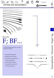
10.2. Upon starting the program the working window appears:<br />
1. In the line “UART Baud rate” select sensor operation speed (factory setting – 9600 bit/s),<br />
2. In the line “COM number” select PC RS232 port number where sensor is connected.<br />
3. The line “Net number of device” defines sensor network address (factory setting for all sensors<br />
– "1")<br />
4. Upon clicking the “Connect” button, RF60X-SP will attempt to establish communication with<br />
sensor with parameters selected as above. If it fails, a ‘communication error’ message is displayed.<br />
5. If communication is successfully established the window changes its form to the following:<br />
<strong>Rev</strong>. G (<strong>26.06</strong>.2008)<br />
Finger GmbH & Co. KG • Schamerloh 84 • 31606 Warmsen • Internet: www.finger-kg.de • email: info@finger-kg.de
<strong>TRIANGULATION</strong> <strong>LASER</strong> <strong>SENSORS</strong>, RF603 <strong>Series</strong><br />
1) In the line "Device Type" the sensor model is displayed<br />
2) In the line "Serial number", a serial number of the sensor is displayed<br />
3) In the line "Base distance", base distance of the sensor is displayed<br />
4) In the line "Measuring range", the sensor working range is displayed<br />
10.3. After communication has been successfully established, it is possible to check sensor performance.<br />
To do so<br />
1) Place an object within the sensor operating range.<br />
2) Pressing "Measure" button displays the results of measurement of object position on the indication<br />
panel and "Oscilloscope" panel. The "Oscilloscope" window shows graphic representation<br />
of the accumulated data. (X-axis – time (Time Sampling Mode) or number of the result (Trigger<br />
Sampling Mode), Y-axis – coordinates). The 06h request type is realized in this case (see par.<br />
8.9)<br />
3) Pressing "Stream start" button enables measurement mode with sampling by time in accordance<br />
with the selected Sampling Period parameter. The 07h request type is realized in this case<br />
(see par. 8.9).<br />
4) By moving the object within the operating range, observe changes of readings on the display<br />
and oscilloscope.<br />
Page 10/22<br />
<strong>Rev</strong>. G (<strong>26.06</strong>.2008)<br />
Finger GmbH & Co. KG • Schamerloh 84 • 31606 Warmsen • Internet: www.finger-kg.de • email: info@finger-kg.de
<strong>TRIANGULATION</strong> <strong>LASER</strong> <strong>SENSORS</strong>, <strong>LDS603</strong> <strong>Series</strong><br />
5) Clicking of the "Stop"/"Stream stop" button deactivates the data transfer.<br />
6) Data coming from the sensor are accumulated and stored in a circular buffer with 10000<br />
measurements storage capacity.<br />
7) By clicking left key of the mouse scale of the graphic can be changed, the right key is used to<br />
drag the graphic image within viewing region. By clicking the right key "Save to the file" menu<br />
is activated.<br />
10.4. Setting parameters of the sensor<br />
The opening part of the "RF60X-SP" application ("Parameter – Value Table ") allows one to edit<br />
and enter the required parameters into both RAM and FLASH memory of the sensor.<br />
- to switch ON/OFF the sensor, click the left mouse key twice in the ‘Value’ field of the ‘Sensor<br />
On/Off’ parameter;<br />
- to enable/disable the analog output, click the left mouse key twice in the ‘Value’ field of the<br />
‘Analog Output On/Off’ parameter;<br />
- to set sampling mode ("UART Control of Sample"), press the key in the "Value" field and<br />
select the mode;<br />
- to set the exchange speed, click the left mouse key in the ‘Value” field of the ‘UART Baud<br />
rate’ line, thus calling out the list of permissible speeds;<br />
- in the "UART Network Address" line set the net address of the sensor;<br />
- in the line "AL Control" set AL output regime;<br />
- in the ‘Laser intensity level’ line, the laser output power level can be selected (mW);<br />
- in the ‘Averaged values counter’ line, select the number of measurements to be averaged directly<br />
in the sensor. Factory setting is "0";<br />
- in the ‘Sampling period’ line, sampling period in 0.1 ms increments is selected;<br />
- in the ‘Max integration time’ filed, it is possible to set the limiting integration time for the<br />
ruler (in microseconds);<br />
- in the lines "Analog Range Begin" и "Analog Range End", it is possible to set the analog<br />
output window boundaries in increments of 1% of the working range. Call out the control<br />
toolbar by clicking twice in the ‘Value’ field:<br />
Pressing the left mouse key activates red cursor which indicates the beginning of the scaling<br />
range, while pressing the right mouse key activates blue cursor indicating the end of<br />
the scaling range. To set up working window boundaries, press the respective button and,<br />
holding it in the pressed position, move the cursor within the sensor measurement region.<br />
Then, boundaries of the selected window will be displayed in the lower line in % (percentage)<br />
of the range.<br />
- in the ‘lock time of result’ line, select the time interval in increments of 5 ms after which<br />
the sensor generates the measurement result as the object comes into the working range<br />
and keeps the last measurement result on the display as the object goes out of the working<br />
range;<br />
- in the ‘Zero point’ line, select the origin of coordinates in units of 0.1% of the range, or<br />
by pressing the ‘Measure’ button place the object in the required point of the working<br />
range and press the ‘Zero set’ key. Now, the origin of coordinates will correspond to the<br />
point selected by you;<br />
Page 11/22<br />
<strong>Rev</strong>. G (<strong>26.06</strong>.2008)<br />
Finger GmbH & Co. KG • Schamerloh 84 • 31606 Warmsen • Internet: www.finger-kg.de • email: info@finger-kg.de
<strong>TRIANGULATION</strong> <strong>LASER</strong> <strong>SENSORS</strong>, <strong>LDS603</strong> <strong>Series</strong><br />
- to select data exchange rate via CAN interface, click left mouse key in the “Value’ field<br />
of the "CAN Baud Rate" line and call the list of permissible rates.<br />
When operated with CAN-interface<br />
- select standard CAN identifier in the "CAN Standard Identifier" line;<br />
- select extended identifier in the "CAN Extended Identifier" line;<br />
- in the "CAN Identifier" line, the identifier type should be set (according to the frame<br />
type) with which the sensor works;<br />
- in the "CAN Mode” line, the CAN interface operation mode should be set.<br />
1) By clicking the right key of the mouse on the left panel "Parameters save" menu is activated.<br />
Select ‘Load’ (to store one parameter) or ‘Load All’ (to store all parameters).<br />
2) Perform testing of the sensor operation with new parameters.<br />
3) To store the new parameters in the sensor memory, click the "Write to FLASH" of "Parameters<br />
save" menu. The sensor will operate with these parameter settings in subsequent<br />
switched on.<br />
4) To choose default sensor parameters, select "Default".<br />
5) To save sensor parameters on the disk, select "Write to file".<br />
6) To read sensor parameters from the disk, select "Read from file".<br />
11. RF60X-SDK. FUNCTIONS DESCRIPTION<br />
Laser sensor is supplied together with SDK -<br />
consisting of:<br />
- dynamic library RF60x.dll,<br />
- file for static linking of DLL to project RF60x.lib,<br />
- definition file RF60x.h.<br />
The SDK allows user to develop his own software products without going into details of the sensor<br />
communications protocol.<br />
11.1. Connection to COM-port (RF60x_OpenPort)<br />
The function RF60x_OpenPort opens COM-port with specified symbolic name, fills in the pointer<br />
to the device descriptor and returns the operation result:<br />
Page 12/22 <strong>Rev</strong>. G (<strong>26.06</strong>.2008)<br />
Finger GmbH & Co. KG • Schamerloh 84 • 31606 Warmsen • Internet: www.finger-kg.de • email: info@finger-kg.de
<strong>TRIANGULATION</strong> <strong>LASER</strong> <strong>SENSORS</strong>, <strong>LDS603</strong> <strong>Series</strong><br />
BOOL RF60x_OpenPort(<br />
LPCSTR lpPort_Name,<br />
DWORD dwSpeed,<br />
HANDLE * lpHandle<br />
);<br />
Parameters:<br />
lpPort_Name – name of COM-port (e.g., “COM1:”), full syntax for COMport<br />
name specification see in MSDN, function CreateFile;<br />
dwSpeed - operation speed through COM-port. The parameter is identical<br />
to field BaudRate in DCB structure described in MSDN;<br />
lpHandle - pointer to the device descriptor;<br />
Returned value:<br />
If COM-port fails to be opened and adjusted, the function will return FALSE, otherwise if COMport<br />
was opened and adjusted successfully the function will return TRUE. More detailed information<br />
about returned errors can be obtained using API function GetLastError described in MSDN.<br />
11.2. Disconnection from COM-port (RF60x_ClosePort).<br />
The function RF60x_ClosePort closes COM-port and returns the operation result:<br />
BOOL RF60x_ClosePort(<br />
HANDLE hHandle<br />
);<br />
Parameters:<br />
hHandle – descriptor of the device obtained from function<br />
RF60x_OpenPort or CreateFile;<br />
Returned value:<br />
If COM-port fails to be closed, the function will return FALSE, otherwise if COM-port was closed<br />
successfully, the function will return TRUE.<br />
11.3. Device identification (RF60x_HelloCmd).<br />
The function RF60x_HelloCmd makes identification of RF60x according to net address and fills<br />
RF60xHELLOANSWER structure:<br />
Page 13/22<br />
typedef struct _RF60x_HELLO_ANSWER_ {<br />
BYTE bDeviceType;<br />
BYTE bcDeviceModificaton;<br />
WORD wDeviceSerial;<br />
WORD wDeviceMaxDistance;<br />
WORD wDeviceRange;<br />
There:<br />
bDeviceType – one byte value, which shows type of the device (for<br />
RF60x this value is equal 60) (type BYTE);<br />
bDeviceModificaton – one byte value, which shows device modification (type<br />
BYTE);<br />
wDeviceSerial – two byte value, which contains serial number of the<br />
device (type WORD);<br />
<strong>Rev</strong>. G (<strong>26.06</strong>.2008)<br />
Finger GmbH & Co. KG • Schamerloh 84 • 31606 Warmsen • Internet: www.finger-kg.de • email: info@finger-kg.de
<strong>TRIANGULATION</strong> <strong>LASER</strong> <strong>SENSORS</strong>, <strong>LDS603</strong> <strong>Series</strong><br />
Page 14/22<br />
wDeviceMaxDistance – two byte value, which contains the base distance of<br />
RF60Х sensor (type WORD);<br />
wDeviceRange – two byte value, which contains the measurement range<br />
of RF60Х sensor (tpe WORD).<br />
BOOL RF60x_HelloCmd (<br />
HANDLE hCOM,<br />
BYTE bAddress,<br />
LPRF60xHELLOANSWER lprfHelloAnswer<br />
);<br />
Parameters:<br />
hCOM – descriptor of the device obtained from function<br />
RF60x_OpenPort or CreateFile;<br />
bAddress - device address;<br />
lprfHelloAnswer - pointer to the RF60xHELLOANSWER structure.<br />
Returned value:<br />
If the device does not respond to identification request, the function returns FALSE, otherwise the<br />
function returns TRUE and fills variable RF60xHELLOANSWER structure<br />
11.4. Reading of parameters (RF60x_ReadParameter)<br />
The function RF60x_ReadParameter reads internal parameters of the RF603 sensor and returns<br />
the current value to the parameters address:<br />
BOOL RF60x_ReadParameter (<br />
HANDLE hCOM,<br />
BYTE bAddress,<br />
WORD wParameter,<br />
DWORD * lpdwValue<br />
);<br />
Parameters:<br />
hCOM – descriptor of the device obtained from function<br />
RF60x_OpenPort, or CreateFile;<br />
bAddress - address of the device;<br />
wParameter - number of parameter, see Table 1,<br />
Table 1<br />
Parameter Description<br />
RF60x_PARAMETER_POWER_STATE Power status of sensor<br />
RF60x_PARAMETER_ANALOG_OUT Connection of analog output<br />
RF60x_PARAMETER_SAMPLE_AND_SYNC Control of sampling and synchronization<br />
RF60x_PARAMETER_NETWORK_ADDRESS Network address<br />
RF60x_PARAMETER_BAUDRATE Data transmission rate through serial port<br />
RF60x_PARAMETER_<strong>LASER</strong>_BRIGHT Laser brightness<br />
RF60x_PARAMETER_AVERAGE_COUNT Number of averaged values<br />
RF60x_PARAMETER_SAMPLING_PERIOD Sampling period<br />
RF60x_PARAMETER_ACCUMULATION_TIME Maximum accumulation time<br />
RF60x_PARAMETER_BEGIN_ANALOG_RANGE Beginning of analog output range<br />
RF60x_PARAMETER_END_ANALOG_RANGE End of analog output range<br />
<strong>Rev</strong>. G (<strong>26.06</strong>.2008)<br />
Finger GmbH & Co. KG • Schamerloh 84 • 31606 Warmsen • Internet: www.finger-kg.de • email: info@finger-kg.de
<strong>TRIANGULATION</strong> <strong>LASER</strong> <strong>SENSORS</strong>, <strong>LDS603</strong> <strong>Series</strong><br />
RF60x_PARAMETER_RESULT_DELAY_TIME Result delay time<br />
RF60x_PARAMETER_ZERO_POINT_VALUE Zero point value<br />
RF60x_PARAMETER_CAN_SPEED Data transmission rate through CAN interface<br />
RF60x_PARAMETER_CAN_STANDARD_ID CAN standard identifier<br />
RF60x_PARAMETER_CAN_EXTENDED_ID Specifies CAN extended identifier<br />
RF60x_PARAMETER_CAN_ID CAN interface identifier<br />
lpdwValue - pointer to WORD-type variable where current parameter<br />
value will be saved.<br />
Returned value:<br />
If the device does not respond to parameter reading request, the function returns FALSE, otherwise<br />
the function returns TRUE and fills variable lpdwValue.<br />
11.5. Saving current parameters in FLASH-memory (RF60x_FlushToFlash).<br />
Function RF60x_FlushToFlash saves all parameters in the FLASH-memory of the RF603 sensor:<br />
BOOL RF60x_FlushToFlash(<br />
HANDLE hCOM,<br />
BYTE bAddress<br />
);<br />
Parameters:<br />
hCOM – descriptor of the device obtained from function<br />
RF60x_OpenPort or CreateFile;<br />
bAddress<br />
Returned value:<br />
- address of the device.<br />
If the device does not respond to request to save all parameters in the FLASH-memory, the function<br />
returns FALSE, otherwise, if record confirm is obtained from the sensor, the function returns<br />
TRUE.<br />
11.6. Restoration of default parameters from FLASH-memory<br />
(RF60x_RestoreFromFlash).<br />
The function RF60x_RestoreFromFlash restores all parameter values in the FLASH by default:<br />
BOOL RF60x_RestoreFromFlash(<br />
HANDLE hCOM,<br />
BYTE bAddress<br />
);<br />
Parameters:<br />
hCOM – descriptor of the device obtained from function<br />
RF60x_OpenPort or CreateFile;<br />
bAddress<br />
Returned value:<br />
- address of the device.<br />
If the device does not respond to request to restore all parameters in the FLASH-memory, the function<br />
returns FALSE, otherwise, if restore confirm is obtained from the sensor, the function returns<br />
TRUE.<br />
Page 15/22<br />
<strong>Rev</strong>. G (<strong>26.06</strong>.2008)<br />
Finger GmbH & Co. KG • Schamerloh 84 • 31606 Warmsen • Internet: www.finger-kg.de • email: info@finger-kg.de
<strong>TRIANGULATION</strong> <strong>LASER</strong> <strong>SENSORS</strong>, <strong>LDS603</strong> <strong>Series</strong><br />
11.7. Latching of the current result (RF60x_LockResult)<br />
BOOL RF60x_LockResult(<br />
HANDLE hCOM,<br />
BYTE bAddress<br />
);<br />
The function RF60x_LockResult restores all parameter values in the FLASH by default:<br />
Parameters:<br />
hCOM – descriptor of the device obtained from function<br />
RF60x_OpenPort or CreateFile;<br />
bAddress - address of the device.<br />
Returned value:<br />
If the device does not respond to result-latching request, the function returns FALSE, otherwise the<br />
function returns TRUE.<br />
11.8. Getting measurement result (RF60x_Measure)<br />
The function RF60x_Measure reads current measurement value from the RF603 sensor. The result<br />
value (D) transmitted by the sensor is normalized in such a way as the value of 4000h (16384) corresponds<br />
to full range of the sensor (S в мм), the result in mm is obtained by the following formula:<br />
X=D*S/4000h (mm) :<br />
BOOL RF60x_Measure(<br />
HANDLE hCOM,<br />
BYTE bAddress,<br />
USHORT * lpusValue<br />
);<br />
Parameters:<br />
hCOM – descriptor of the device obtained from function<br />
RF60x_OpenPort or CreateFile;<br />
bAddress - address of the device.<br />
lpusValue - pointer to USHORT/WORD-type variable containing the<br />
result D.<br />
Returned value:<br />
If the device does not respond to result request, the function returns FALSE, otherwise, if the restore<br />
confirm is obtained from the sensor, the function returns TRUE.<br />
11.9. Starting measurement stream (RF60X_StartStream)<br />
The function RF60x_StartStream switches RF603 sensor to the mode where continuous transmission<br />
of measurement results takes place:<br />
BOOL RF60x_StartStream(<br />
HANDLE hCOM,<br />
BYTE bAddress<br />
);<br />
Parameters:<br />
hCOM – descriptor of the device obtained from function<br />
RF60x_OpenPort or CreateFile;<br />
bAddress - address of the device.<br />
Returned value:<br />
Page 16/22<br />
<strong>Rev</strong>. G (<strong>26.06</strong>.2008)<br />
Finger GmbH & Co. KG • Schamerloh 84 • 31606 Warmsen • Internet: www.finger-kg.de • email: info@finger-kg.de
<strong>TRIANGULATION</strong> <strong>LASER</strong> <strong>SENSORS</strong>, <strong>LDS603</strong> <strong>Series</strong><br />
If the device fails to be switched to continuous measurement transmission mode, the function returns<br />
FALSE, otherwise the function returns TRUE.<br />
11.10. Stopping measurement stream (RF60x_StopStream)<br />
The function RF60x_StopStream switches the sensor from continuous measurement transmission<br />
mode to the “request-response” mode:<br />
BOOL RF60x_StartStream(<br />
HANDLE hCOM,<br />
BYTE bAddress<br />
);<br />
Parameters:<br />
hCOM – descriptor of the device obtained from function<br />
RF60x_OpenPort or CreateFile;<br />
bAddress - address of the device.<br />
Returned value:<br />
If the device fails to be stopped in the continuous data transmission mode, the function returns<br />
FALSE, otherwise the function returns TRUE.<br />
11.11. Getting measurement results from the stream (RF60X_GetStreamMeasure)<br />
The function RF60x_GetStreamMeasure reads data from the COM-port input buffer which are<br />
received from RF603 sensor after successful execution of the RF60xX_StartStream function. The<br />
data arrive in the buffer at a rate specified in the RF603 sensor parameters. Since depth of the input<br />
buffer is limited to 1024 bytes, it is preferable to read data with periodicity uqual to that specified in<br />
the RF603 sensor parameters. The parameter lpusValue is identical to the parameter lpus-<br />
Value in the RF60x_Measure function.<br />
BOOL RF60x_GetStreamMeasure(<br />
HANDLE hCOM,<br />
USHORT * lpusValue<br />
);<br />
Parameters:<br />
hCOM – descriptor of the device obtained from function<br />
RF60x_OpenPort or CreateFile;<br />
lpusValue - pointer to USHORT/WORD-type variable containing the<br />
result D.<br />
Returned value:<br />
If there are no data in the buffer, the function returns FALSE, otherwise the function returns TRUE<br />
and fills the value lpusValue.<br />
11.12. Transmission of user data (RF60x_CustomCmd)<br />
The function RF60x_CustomCmd is used for transmission and/or reception of data from in <strong>LDS603</strong><br />
sensor parameters <strong>LDS603</strong>.<br />
Page 17/22<br />
<strong>Rev</strong>. G (<strong>26.06</strong>.2008)<br />
Finger GmbH & Co. KG • Schamerloh 84 • 31606 Warmsen • Internet: www.finger-kg.de • email: info@finger-kg.de
<strong>TRIANGULATION</strong> <strong>LASER</strong> <strong>SENSORS</strong>, <strong>LDS603</strong> <strong>Series</strong><br />
BOOL RF60x_CustomCmd(<br />
HANDLE hCOM,<br />
char * pcInData,<br />
DWORD dwInSize,<br />
char * pcOutData,<br />
DWORD * pdwOutSize<br />
);<br />
Parameters:<br />
hCOM – descriptor of the device obtained from function<br />
RF60x_OpenPort or CreateFile;<br />
pcInData - pointer to data array which will be transmitted to RF603<br />
sensor. If no data need to be transmitted, pcInData must be NULL and dwInSize must be 0.<br />
dwInSize - size of transmitted data. If no data need to be transmitted,<br />
this parameter must be 0.<br />
pcOutData - pointer to data array where data received from RF603 will<br />
be saved. If no data need to be received, pcOutData must be NULL.<br />
pdwOutSize - pointer to the variable containing size of data to be received.<br />
If no data need to be received, this parameter must be NULL. After successful receipt of<br />
data, the amount of read bytes will be recorded to the variable where this parameter points to.<br />
Returned value:<br />
If transmission or reception of bytes fails, the function returns FALSE, otherwise the function returns<br />
TRUE.<br />
11.13. Functions for operation of sensors connected to FTDI-based USB.<br />
To work with FTDI-based USB devices, this library supports functions operating through D2XX<br />
library of FTDI. Performance of the functions is identical to that of the functions used for operation<br />
through serial port, the main difference being the presence of FTDI_ prefix in the function name,<br />
for example: “getting result” function for serial port is RF60x_Measure while for FTDI USB<br />
devices it is RF60x_FTDI_Measure.<br />
Page 18/22<br />
<strong>Rev</strong>. G (<strong>26.06</strong>.2008)<br />
Finger GmbH & Co. KG • Schamerloh 84 • 31606 Warmsen • Internet: www.finger-kg.de • email: info@finger-kg.de
<strong>TRIANGULATION</strong> <strong>LASER</strong> <strong>SENSORS</strong>, <strong>LDS603</strong> <strong>Series</strong><br />
EXAMPLE 1<br />
HANDLE hRF60x = INVALID_HANDLE_VALUE;<br />
DWORD dwValue;<br />
USHORT usMeasured;<br />
RF60XHELLOANSWER hlans;<br />
// Clear structure RF60xHELLOANSWER<br />
memset(&hlans, 0x00, sizeof(RF60xHELLOANSWER));<br />
// Open COM-port<br />
if (!RF60X_OpenPort("COM2:", CBR_9600, &hRF60X)<br />
return (FALSE);<br />
// Interrogate device<br />
if (RF60X_HelloCmd( hRF60x, 1, &hlans ))<br />
{<br />
}<br />
Page 19/22<br />
/////////////////////////////////////////////////<br />
// //<br />
// After successful execution of RF60x_HelloCmd//<br />
// the structure hlans contains information //<br />
// about RF603 sensor that responded to request//<br />
// //<br />
/////////////////////////////////////////////////<br />
//Read parameter: Laser brightness<br />
RF60x_ReadParameter(<br />
hRF60x,<br />
1,<br />
RF60x_PARAMETER_<strong>LASER</strong>_BRIGHT,<br />
&dwValue<br />
);<br />
/* dwValue contains laser brightness values */<br />
//Obtain distance values from RF603 sensor<br />
RF60x_Measure( hRF60x, 1, &usMeasured );<br />
/* usMeasured contains measurement result */<br />
RF60x_ClosePort( hRF60x );<br />
<strong>Rev</strong>. G (<strong>26.06</strong>.2008)<br />
Finger GmbH & Co. KG • Schamerloh 84 • 31606 Warmsen • Internet: www.finger-kg.de • email: info@finger-kg.de
<strong>TRIANGULATION</strong> <strong>LASER</strong> <strong>SENSORS</strong>, <strong>LDS603</strong> <strong>Series</strong><br />
EXAMPLE 2 (how to get a stream of result)<br />
Page 20/22<br />
HANDLE hRF60x = INVALID_HANDLE_VALUE;<br />
USHORT usMeasured;<br />
RF60xHELLOANSWER hlans;<br />
memset(&hlans, 0x00, sizeof(RF60xHELLOANSWER));<br />
RF60x_OpenPort("COM2:", CBR_9600, &hRF60x);<br />
if (RF60x_HelloCmd( hRF60x, 1, &hlans ))<br />
{<br />
printf("Dev modify\t: %d\r\nDev type\t: %d\r\nDev max dist\t:<br />
%d\r\nDev range\t: %d\r\nDev serial\t: %d\r\n",<br />
hlans.bDeviceModificaton,<br />
hlans.bDeviceType,<br />
hlans.wDeviceMaxDistance,<br />
hlans.wDeviceRange,<br />
hlans.wDeviceSerial<br />
);<br />
if (!RF60x_WriteParameter( hRF60x, 1,<br />
RF60x_PARAMETER_SAMPLING_PERIOD, 500 ))<br />
return (-1);<br />
if (!RF60x_StartStream(hRF60x, 1))<br />
return (-1);<br />
RF60x_GetStreamMeasure(hRF60x, &usMeasured);<br />
printf("Measure \t: %d\r\n", usMeasured);<br />
RF60x_GetStreamMeasure(hRF60x, &usMeasured);<br />
printf("Measure \t: %d\r\n", usMeasured);<br />
RF60x_StopStream(hRF60x, 1);<br />
} else printf("rs232 error!\r\n");<br />
RF60x_ClosePort( hRF60x );<br />
EXAMPLE 3 (how to get a result with latching)<br />
for (int i=0;i
<strong>TRIANGULATION</strong> <strong>LASER</strong> <strong>SENSORS</strong>, <strong>LDS603</strong> <strong>Series</strong><br />
Page 21/22<br />
ANNEX<br />
Protective housing<br />
Air-cooled protective housing can be used when operating sensor under conditions of elevated<br />
temperatures and high pollution levels. Overall and mounting dimensions of the housing are shown<br />
in Fig. 1A. Basic requirements:<br />
1) Temperature of pressed air at the sensor input
<strong>TRIANGULATION</strong> <strong>LASER</strong> <strong>SENSORS</strong>, <strong>LDS603</strong> <strong>Series</strong><br />
Page 22/22<br />
12. COMPLETE DELIVERY PACKAGE<br />
The delivery package includes:<br />
RF603 <strong>Series</strong> sensor 1 pc<br />
Installation CD with RF60X-SP (executable module) and SDK 1 pc<br />
13. WARRANTY POLICY<br />
Warranty assurance for the sensor RF603 - 18 months from the date of putting in operation;<br />
warranty shelf-life - 12 months.<br />
Finger GmbH & Co. KG • Schamerloh 84 • 31606 Warmsen • Internet: www.finger-kg.de • email: info@finger-kg.de<br />
<strong>Rev</strong>. G (<strong>26.06</strong>.2008)