Create successful ePaper yourself
Turn your PDF publications into a flip-book with our unique Google optimized e-Paper software.
SLS7000 Users manual LMI Sel<strong>co</strong>m AB<br />
SLS1 SLS2<br />
. . . . .<br />
. . . . .<br />
. . . . .<br />
H1<br />
. . . . .<br />
. . . . .<br />
. . . . .<br />
C<br />
D<br />
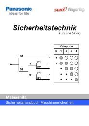
Figure 6: Rear panel<br />
. . . . .<br />
. . . . .<br />
. . . . .<br />
H2<br />
. . . . .<br />
. . . . .<br />
. . . . .<br />
A Power receptacle<br />
B Laser Remote Control, LRC <strong>co</strong>nnector Screw terminal with a jumper <strong>co</strong>ntrolling the<br />
LASER ON signal to both SLS7000 1 and SLS7000 2.The lasers are on if power is<br />
on AND the jumper or a remote switch is closed.<br />
C Two SLS7000 sensors <strong>co</strong>nnectors, SLS7000 1 and SLS7000 2. Female Socket<br />
<strong>co</strong>nnectors for easy <strong>co</strong>nnection of one or two SLS7000 sensors with DSUBmin<br />
<strong>co</strong>nnectors.<br />
Front view, DSUB-15 pin, socket <strong>co</strong>nnector<br />
SLS Powerbox 24<br />
<strong>co</strong>nnectors SLS1 and SLS2<br />
15<br />
. . . . .<br />
. . . . .<br />
. . . . .<br />
2000-05-24 813364 P1 7<br />
A<br />
LRC<br />
1 Receive data, RS232-C<br />
9 Transmit data, RS232-C<br />
3 CLOCK, SELCOM interface or RS422 Rx+<br />
4 CLOCK-inv, SELCOM interface or RS422 Rx-<br />
5 DATA, SELCOM interface or RS422 Tx+<br />
6 DATA-inv, SELCOM interface or RS422 Tx-<br />
8 Invalid out-, (when analog interface is used)<br />
12 Invalid out + , (when analog interface is used)<br />
13 Analog out<br />
11 Ground<br />
14 Laser ON, (+24 VDC)<br />
15 Power, (+24 VDC)<br />
1<br />
Figure 7: SLS7000 1 and SLS7000 2 <strong>co</strong>nnector female pin<br />
<strong>co</strong>nfiguration<br />
D Two output <strong>co</strong>nnectors, H1 and H2.Male Pin <strong>co</strong>nnectors with capacity to output all<br />
signals available from the SLS7000 sensor.<br />
B