Create successful ePaper yourself
Turn your PDF publications into a flip-book with our unique Google optimized e-Paper software.
User’s <strong>Manual</strong><br />
SLS 7000
SLS7000 Users manual LMI Sel<strong>co</strong>m AB /<strong>finger</strong> GmbH & Co KG<br />
Contents<br />
Contents....................................................................................................................................................................................... 2<br />
1 General information............................................................................................................................................................... 3<br />
2 Component description ......................................................................................................................................................... 4<br />
2.1 Sensor description .......................................................................................................................................................... 4<br />
2.2 Accessories ...................................................................................................................................................................... 6<br />
2.2.1 Cables ....................................................................................................................................................................... 6<br />
2.2.2 SLS Power unit 24.................................................................................................................................................. 6<br />
2.2.3 Video Camera.......................................................................................................................................................... 9<br />
3 Laser safety ........................................................................................................................................................................... 10<br />
3.1 Classification................................................................................................................................................................. 10<br />
3.2 Warning labels .............................................................................................................................................................. 10<br />
4 Installing ................................................................................................................................................................................ 11<br />
4.1 Pin <strong>co</strong>nfiguration .......................................................................................................................................................... 11<br />
4.2 Cable requirements....................................................................................................................................................... 12<br />
4.2.1 Cable length........................................................................................................................................................... 12<br />
4.2.2 Signal leads with demand for twisted pairs...................................................................................................... 12<br />
4.2.3 Signal leads without demand for twisted pairs................................................................................................ 12<br />
4.2.4 Power supply leads............................................................................................................................................... 12<br />
4.2.5 Cable screening..................................................................................................................................................... 12<br />
4.3 Analog output................................................................................................................................................................ 13<br />
4.3.1 General <strong>co</strong>nsiderations........................................................................................................................................ 13<br />
4.4 Load <strong>co</strong>nditions for analog and invalid outputs...................................................................................................... 14<br />
4.4.1 Analog output load............................................................................................................................................... 14<br />
4.4.2 Optional noise filtering........................................................................................................................................ 14<br />
4.4.3 Alternative <strong>co</strong>nnections for valid output.......................................................................................................... 15<br />
4.5 Mechanical mounting .................................................................................................................................................. 16<br />
4.5.1 Sensor head mounting.......................................................................................................................................... 16<br />
4.5.2 SLS-PPU mounting.............................................................................................................................................. 17<br />
5 Technical specification........................................................................................................................................................ 17<br />
5.1 general ............................................................................................................................................................................ 17<br />
5.2 Performance specification........................................................................................................................................... 17<br />
5.3 Laser beam characteristics .......................................................................................................................................... 18<br />
6 Hints on <strong>co</strong>rrect use............................................................................................................................................................. 19<br />
7 Communication interfaces .................................................................................................................................................. 21<br />
7.1 General ........................................................................................................................................................................... 21<br />
7.2 Sel<strong>co</strong>m Serial interface................................................................................................................................................ 21<br />
7.3 SLS-asynch-1, Proto<strong>co</strong>l............................................................................................................................................... 22<br />
8 Ordering and spare parts information ............................................................................................................................... 33<br />
LMI Sel<strong>co</strong>m AB<br />
B0ox 250,<br />
S-43325 Partille<br />
SWEDEN<br />
Tel: +46 (0)31 336 25 10<br />
Main +46 (0)31 336 25 00<br />
Fax: +46 (0)31 44 61 79<br />
Internet: http://www.lmint.<strong>co</strong>m<br />
LMI Sel<strong>co</strong>m, INC.<br />
21666 Melrose Ave.<br />
SOUTHFIELD MI 48075<br />
USA<br />
Tel: +1 248 355 5900<br />
Fax: +1 248 355 3283<br />
LMI Sensors-95<br />
Valkenburgweg 223<br />
6419 AT Heerlen<br />
Netherlands<br />
Tel: +31 45-571 93 00<br />
Fax: +31 45-574 25 00<br />
LMI DynaVision<br />
205-7088 Ventura Street<br />
Delta, BC, V4G-1H5<br />
Canada<br />
Tel: +1 604-940 0141<br />
Fax: +1 604-940 0793<br />
Printed in Sweden<br />
2000-05-24 813364 P1 2
SLS7000 Users manual LMI Sel<strong>co</strong>m AB<br />
1 General information<br />
The SLS7000 Specular reflective sensor is intended for measuring surfaces ranging<br />
from perfect mirrors to semi-specular surfaces such as aluminium, stainless steel and<br />
other reflective materials.<br />
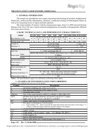
The specular reflective triangulation principle provides, as opposed to the more<br />
<strong>co</strong>mmonly used diffuse reflection triangulation, a principally higher capability for highresolution<br />
data on shiny and reflective materials and surface structures.<br />
The SLS7000 has been designed to further stretch the area of use towards difficult<br />
surface structure materials like the <strong>co</strong>ld rolled special steel used in hard disk drive<br />
read/write head suspensions.<br />
Resolution in the sub micron range is typically achievable in such applications.<br />
.<br />
Fig. 2<br />
The specular reflection sensor<br />
Picks up a major part of the reflected<br />
beam.<br />
The wide triangulation angle and 10micron<br />
sized laser spot further<br />
enhances the basic triangulation<br />
resolution.<br />
Fig. 1.<br />
The diffuse reflection sensor will only<br />
“see” a minor part of the beam reflected<br />
from a semi-specular surface.<br />
2000-05-24 813364 P1 3
SLS7000 Users manual LMI Sel<strong>co</strong>m AB<br />
2 Component description<br />
2.1 Sensor description<br />
The basic SLS7000 sensor <strong>co</strong>nsists of two parts:<br />
• SLS7000 Sensor head<br />
• SLS-PPU <strong>co</strong>ntroller<br />
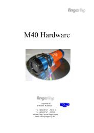
Figure 3. SLS7000 Sensor head<br />
The 3 m sensor cable <strong>co</strong>nnects to the SLS-PPU with a high density <strong>co</strong>nnector.<br />
A red LED on the sensor top surface indicates sensor power ON.<br />
2000-05-24 813364 P1 4
SLS7000 Users manual LMI Sel<strong>co</strong>m AB<br />
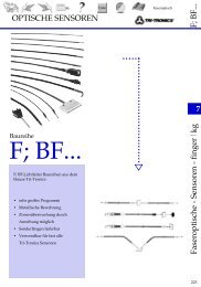
Figure 4. SLS-PPU <strong>co</strong>ntroller<br />
The 2 m cable from the SLS-PPU <strong>co</strong>ntroller <strong>co</strong>nnects to the user Power supply/data<br />
acquisition equipment via a 15 pin high density D-sub <strong>co</strong>nnector.<br />
Two LED’s on the top surface of the <strong>co</strong>ntroller indicates valid data in the<br />
measurement range (green LED) or Invalid data/out of range (yellow LED) <strong>co</strong>ndition.<br />
A <strong>co</strong>ntinuous switching between Yellow and Red LED indicates a malfunction in the<br />
sensor DSP (Digital Signal Processor)<br />
2000-05-24 813364 P1 5
SLS7000 Users manual LMI Sel<strong>co</strong>m AB<br />
2.2 Accessories<br />
2.2.1 Cables<br />
To facilitate different installation needs a variety of extension and <strong>co</strong>nnection cables<br />
are available for use with the sensor stand-alone or in <strong>co</strong>mbination with the SLS<br />
Power Unit.<br />
Contact LMI Sel<strong>co</strong>m or your local representative for more information.<br />
2.2.2 SLS Power unit 24<br />
The SLS Power unit 24 can supply one or two SLS7000 sensor sensors.<br />
The customer must provide a power cable of suitable length, fitting the power<br />
receptacle.<br />
Figure 5: Front panel<br />
POWER ON<br />
A B<br />
A: Key switch. The key is removable when power is off<br />
B: Power ON LED. Illuminated when power is turned on. Color: Green.<br />
2000-05-24 813364 P1 6
SLS7000 Users manual LMI Sel<strong>co</strong>m AB<br />
SLS1 SLS2<br />
. . . . .<br />
. . . . .<br />
. . . . .<br />
H1<br />
. . . . .<br />
. . . . .<br />
. . . . .<br />
C<br />
D<br />
Figure 6: Rear panel<br />
. . . . .<br />
. . . . .<br />
. . . . .<br />
H2<br />
. . . . .<br />
. . . . .<br />
. . . . .<br />
A Power receptacle<br />
B Laser Remote Control, LRC <strong>co</strong>nnector Screw terminal with a jumper <strong>co</strong>ntrolling the<br />
LASER ON signal to both SLS7000 1 and SLS7000 2.The lasers are on if power is<br />
on AND the jumper or a remote switch is closed.<br />
C Two SLS7000 sensors <strong>co</strong>nnectors, SLS7000 1 and SLS7000 2. Female Socket<br />
<strong>co</strong>nnectors for easy <strong>co</strong>nnection of one or two SLS7000 sensors with DSUBmin<br />
<strong>co</strong>nnectors.<br />
Front view, DSUB-15 pin, socket <strong>co</strong>nnector<br />
SLS Powerbox 24<br />
<strong>co</strong>nnectors SLS1 and SLS2<br />
15<br />
. . . . .<br />
. . . . .<br />
. . . . .<br />
2000-05-24 813364 P1 7<br />
A<br />
LRC<br />
1 Receive data, RS232-C<br />
9 Transmit data, RS232-C<br />
3 CLOCK, SELCOM interface or RS422 Rx+<br />
4 CLOCK-inv, SELCOM interface or RS422 Rx-<br />
5 DATA, SELCOM interface or RS422 Tx+<br />
6 DATA-inv, SELCOM interface or RS422 Tx-<br />
8 Invalid out-, (when analog interface is used)<br />
12 Invalid out + , (when analog interface is used)<br />
13 Analog out<br />
11 Ground<br />
14 Laser ON, (+24 VDC)<br />
15 Power, (+24 VDC)<br />
1<br />
Figure 7: SLS7000 1 and SLS7000 2 <strong>co</strong>nnector female pin<br />
<strong>co</strong>nfiguration<br />
D Two output <strong>co</strong>nnectors, H1 and H2.Male Pin <strong>co</strong>nnectors with capacity to output all<br />
signals available from the SLS7000 sensor.<br />
B
SLS7000 Users manual LMI Sel<strong>co</strong>m AB<br />
Technical specification:<br />
Front view, DSUB-15 pin, pin <strong>co</strong>nnector SLS Powerbox 24<br />
<strong>co</strong>nnectors H1 and H2<br />
1<br />
. . . . .<br />
. . . . .<br />
. . . . .<br />
2000-05-24 813364 P1 8<br />
15<br />
1 Receive data, RS232-C<br />
9 Transmit data, RS232-C<br />
3 CLOCK, SELCOM interface or RS422 Rx+<br />
4 CLOCK-inv, SELCOM interface or RS422 Rx-<br />
5 DATA, SELCOM interface or RS422 Tx+<br />
6 DATA-inv, SELCOM interface or RS422 Tx-<br />
8 Invalid out-, (when analog interface is used)<br />
12 Invalid out + , (when analog interface is used)<br />
13 Analog out<br />
11 Ground<br />
Dimensions:<br />
Length: 218.6 mm (8.5 inches)<br />
Height: 62.8 mm (2.5 inches)<br />
Width: 143.7 mm (5.6 inches)<br />
Weight: 1.4 <strong>kg</strong> (3.1 lbs)<br />
Environmental <strong>co</strong>nditions:<br />
Protection class: IP50 NEMA 1<br />
Figure 8: H1 and H2 <strong>co</strong>nnector male pin <strong>co</strong>nfiguration<br />
Temperature:<br />
Operating: 0-50 °C (32-120°F)<br />
Storage: -30-70 °C (-20-160°F)<br />
Power requirements:<br />
Input voltage: 110/230 VAC (± 10 %)<br />
Line frequency: 50/60 Hz<br />
Power <strong>co</strong>nsumption: 40 W (50 W peak at startup)
SLS7000 Users manual LMI Sel<strong>co</strong>m AB<br />
2.2.3 Video Camera<br />
An optional video camera may be ordered with the sensor to facilitate exact operator<br />
positioning of the 10-micron laser spot on the work object.<br />
Video parts:<br />
• Sensor integrated video camera<br />
• External camera <strong>co</strong>ntroller with standard video output on BNC <strong>co</strong>nnector<br />
(specify video standard EIA or CCIR)<br />
• Video lens f+12<br />
• 110-240 Vac Power adaptor (Specify US or Europe <strong>co</strong>nnector type)<br />
The video camera option is preferably ordered with the sensor but may be added as<br />
an update.<br />
Video camera and camera <strong>co</strong>ntroller <strong>co</strong>me as a factory-tuned set and must be<br />
serviced and replaced as one part.<br />
To avoid problems finding a suitable video monitor for displaying the video camera<br />
scene, it’s important to specify the <strong>co</strong>rrect video signal type, EIA for North America,<br />
Japan and CCIR for Europe.<br />
The latter also applies for the power adaptor that requires a specification for use in<br />
the USA or Europe.<br />
The camera <strong>co</strong>ntroller is delivered with its user settable <strong>co</strong>ntrol switches in the<br />
“automatic” position. These settings will for most applications provide a sufficient<br />
image quality. All accessible switches on the camera <strong>co</strong>ntroller are free to change in<br />
order to enhance image quality.<br />
To enhance image quality like <strong>co</strong>ntrast and definition of laser spot on scene it is also<br />
re<strong>co</strong>mmended to add lighting to the scene.<br />
Depending on requirement, scene lighting can be ac<strong>co</strong>mplished with everything from<br />
an ordinary office table lamp to sophisticated light guide fibres. The main<br />
<strong>co</strong>nsideration when adding light is to avoid possible heating and thereby expansion<br />
and movement of the measurement object.<br />
The sensor data will not be influenced by added light as such, although the possible<br />
heating of the sensor may cause initial drift until a stable sensor housing temperature<br />
is established.<br />
2000-05-24 813364 P1 9
SLS7000 Users manual LMI Sel<strong>co</strong>m AB<br />
3 Laser safety<br />
3.1 Classification<br />
Sensors in the SLS7000 series are classified Class ll (FDA), class 2 (IEC 825-<br />
1:1993)<br />
Special precautions are only required to prevent <strong>co</strong>ntinuous viewing of the direct<br />
beam. A momentary exposure, limited by the blinking reflex (t
SLS7000 Users manual LMI Sel<strong>co</strong>m AB<br />
4 Installing<br />
4.1 Pin <strong>co</strong>nfiguration<br />
DSUB-15 pin, pin <strong>co</strong>nnector CONTACT series R2.5-16 pin, pin <strong>co</strong>nnector<br />
1<br />
. . . . .<br />
. . . . .<br />
. . . . .<br />
15<br />
11<br />
12<br />
1<br />
1 Receive data, RS232-C<br />
9 Transmit data, RS232-C<br />
3 CLOCK, SELCOM interface or RS422 Rx+<br />
4 CLOCK-inv, SELCOM interface or RS422 Rx-<br />
5 DATA, SELCOM interface or RS422 Tx+<br />
6 DATA-inv, SELCOM interface or RS422 Tx-<br />
8 Invalid out-, (when analog interface is used)<br />
12 Invalid out+, (when analog interface is used)<br />
13 Analog out<br />
11 Ground<br />
14 Laser ON, (+24 VDC)<br />
15 Power, (+24 VDC)<br />
16<br />
Figure 11: 15 pin DSUB miniature, Male pin <strong>co</strong>nnector (3 rows) and 16 pin<br />
CONTACT series R2.5, male pin <strong>co</strong>nnector, front views.<br />
Note: The DSUBmin <strong>co</strong>nnector meets IP50 (NEMA 1). The <strong>co</strong>nnector may require<br />
extra protection if mounted in a humid environment, although dust alone will not<br />
require any added precautions.<br />
The CONTACT <strong>co</strong>nnector meets IP65 (NEMA 4) when <strong>co</strong>nnected with mating<br />
<strong>co</strong>nnector.<br />
2000-05-24 813364 P1 11
SLS7000 Users manual LMI Sel<strong>co</strong>m AB<br />
4.2 Cable requirements<br />
4.2.1 Cable length<br />
Interface Pin number Max cable length<br />
RS 232 1, 9, 11 15m<br />
RS 422 or Sel<strong>co</strong>m serial 3, 4, 5, 6<br />
100 m<br />
Analog 11, 13 100 m (
SLS7000 Users manual LMI Sel<strong>co</strong>m AB<br />
4.3 Analog output<br />
4.3.1 General <strong>co</strong>nsiderations<br />
The analog current output of the SLS7000 sensor is derived from the same high<br />
performance and accuracy digital distance data as available over the Sel<strong>co</strong>m Serial,<br />
RS232 and RS422 interfaces.<br />
The D/A <strong>co</strong>nversion is made from a 12 bit’s distance data value.<br />
As a <strong>co</strong>mplement to the analog output, an ”Invalid out” signal is available. The<br />
sensors are available in two versions (factory set, not to be changed by the user!)<br />
regarding the state of the analog output when data is <strong>co</strong>nsidered ”invalid”:<br />
”Hold latest valid” i.e. the analog output current is held at the latest valid D/A<br />
<strong>co</strong>nverted data value.<br />
”Zero out on invalid” is only available with 4-20 mA output. The analog current<br />
output is set to 0 mA as long as data is <strong>co</strong>nsidered invalid.<br />
IMPORTANT: The transformation of the current output to engineering units (i.e. mm,<br />
inches etc.) in a <strong>co</strong>ntrol <strong>co</strong>mputer, PLC etc. requires the use of a ”scale factor (SFI )”<br />
that defines the relation between current output and engineering unit.<br />
Sensor type 0-20 mA SFi (mm/mA) 4-20 mA SFi (mm/mA)<br />
SLS7001/15 0,0512 0,064<br />
It is NOT CORRECT and will lead to erroneous results if the measurement range is<br />
simply divided by the current range!!<br />
If an absolute distance between the target and the sensor (or some other ref. Point)<br />
is to be <strong>co</strong>mputed, it is necessary to be aware of the fact that the fixed calibration<br />
point between the sensor and the current output is defined at the Stand-Off distance<br />
as being 10 mA for a 0-20 mA sensor and 12 mA for a 4-20 mA sensor.<br />
2000-05-24 813364 P1 13
SLS7000 Users manual LMI Sel<strong>co</strong>m AB<br />
4.4 Load <strong>co</strong>nditions for analog and invalid outputs<br />
4.4.1 Analog output load<br />
The current output load resistance should not exceed 500 ohms. A separate return<br />
path to ground should be provided via pin 11 (GND). The total resistance in the<br />
analog out lead and the ground lead must not exceed 15 ohms.<br />
SLS5000 <strong>co</strong>nnector<br />
0-20mA<br />
pin 13<br />
pin 11<br />
Figure 12: Example of <strong>co</strong>nnection:<br />
Note:<br />
max 500 ohm<br />
max 100 meters<br />
max 7.5 ohm /signal lead<br />
2000-05-24 813364 P1 14<br />
+<br />
0-10 VDC<br />
We re<strong>co</strong>mmend the use of temperature stable resistors to reduce the effects of<br />
voltage variations due to resistance changes.<br />
Always turn the power off before <strong>co</strong>nnecting or dis<strong>co</strong>nnecting the analog output load.<br />
4.4.2 Optional noise filtering<br />
Due to cable cross talk, the spectral characteristics of the analog current output, as<br />
measured over a 100 Ohm resistor, may have the following principal appearance:<br />
SLS7000 signal spectrum<br />
Figure 13: Illustration of spectrum<br />
HF-noise spectrum<br />
1 10 100 kHz<br />
-
SLS7000 Users manual LMI Sel<strong>co</strong>m AB<br />
The analog output of the SLS7000 sensor mainly finds its use in low bandwidth,<br />
industrial measurement and <strong>co</strong>ntrol applications. The signal <strong>co</strong>nversion equipment in<br />
such applications is normally band limited to low frequencies making the system<br />
insensitive to high frequency noise.<br />
For some wide band applications like vibration analysis or when the signal is to be<br />
manually studied with an oscillos<strong>co</strong>pe, the high frequency noise may be a problem. In<br />
these cases an anti-aliasing filter may be added between the load resistor and the<br />
registration equipment.<br />
A simple but in most cases sufficient filter is shown below. The <strong>co</strong>mponents as<br />
chosen will give an upper frequency limitation of 1.6 kHz. It is important that the filter<br />
and the registration equipment is <strong>co</strong>nnected with as short cabling as possible to<br />
avoid additional noise pick-up.<br />
SLS7000<br />
<strong>co</strong>nnector<br />
pin 13<br />
pin 11<br />
Figure 14: Example of filter<br />
I (output)<br />
Load<br />
resistor<br />
4.4.3 Alternative <strong>co</strong>nnections for valid output<br />
10 k ohm<br />
10 nF<br />
The output transistor <strong>co</strong>nducts as long as the measurement is valid.<br />
Figure 15: Example of <strong>co</strong>nnection (current sink)<br />
+ 5V<br />
Valid out<br />
100 ohm<br />
SLS 7000<br />
Connector<br />
I = max 50 mA<br />
Pin 12<br />
Registration<br />
equipment<br />
2000-05-24 813364 P1 15<br />
Pin 8<br />
V+<br />
4.7 k ohm<br />
LOW = Valid<br />
HIGH = Invalid
SLS7000 Users manual LMI Sel<strong>co</strong>m AB<br />
Figure 16: Example of <strong>co</strong>nnection (current source)<br />
+ 5V<br />
Valid out<br />
4.5 Mechanical mounting<br />
4.5.1 Sensor head mounting<br />
100 ohm<br />
I = max 50 mA<br />
SLS 7000<br />
<strong>co</strong>nnector<br />
pin 12<br />
2000-05-24 813364 P1 16<br />
pin 8<br />
V+<br />
LOW = Invalid<br />
HIGH = Valid<br />
4.7 k ohm<br />
Due to the high resolution of the sensor, careful <strong>co</strong>nsideration must be paid to the<br />
mounting of the sensor head.<br />
The way of mounting should be targeted at avoiding measurement errors due to:<br />
• Thermal expansion and mechanical instability in the mounting fixture<br />
• Mechanical tension in the sensor housing when tightening the mounting<br />
screws.<br />
• Pick up of electro-magnetic noise and disturbances.<br />
Normal <strong>co</strong>nsiderations for precision measurement equipment should be sufficient for<br />
the overall fixture stability.<br />
For the actual fitting of the sensor to a mounting surface, the flatness must be<br />
<strong>co</strong>nsidered. If a sufficient flatness can’t be guaranteed, it’s re<strong>co</strong>mmended to use<br />
small diameter, precision washers to distance the sensor slightly from it’s mounting<br />
surface.<br />
If strong ground current/loops from welding equipment, electrical motors etc. can be<br />
expected in the sensors vicinity, it’s re<strong>co</strong>mmended to mount the sensor electrically<br />
isolated from the mounting structure. This is also re<strong>co</strong>mmended when several<br />
sensors are mounted close to each other and powered from the same supply.
SLS7000 Users manual LMI Sel<strong>co</strong>m AB<br />
4.5.2 SLS-PPU mounting<br />
Mounting of the SLS-PPU is less critical from mechanical strain <strong>co</strong>nsiderations.<br />
Care must of <strong>co</strong>urse be taken to avoid unnecessary cable bending and strain on<br />
<strong>co</strong>nnectors.<br />
To isolate the SLS-PPU, the unit is delivered with special nylon washers that fit in the<br />
mounting holes. Use of the isolation washers is always re<strong>co</strong>mmended.<br />
5 Technical specification<br />
5.1 general<br />
LASER SOURCE ENVIRONMENTAL<br />
Laser type GaAIAs Operating temp. C/F 0-50/32-122<br />
Laser Class ll/2 Temp. fluctuation % of mr/C 0,01<br />
Max. output power mW Relative humidity %
SLS7000 Users manual LMI Sel<strong>co</strong>m AB<br />
5.3 Laser beam characteristics<br />
Figure 17. Laser beam characteristics (principal)<br />
Focal point at S.O.<br />
Far End (F.E.) of M.R. Close End (C.E.) of M.R.<br />
Beam diameter at S.O.: 10 – 20 um<br />
Beam diameter at S.O. +/- 0,45 mm: 70 - 90 um<br />
The beam diameter is specified to <strong>co</strong>ntain 90 % of the beam energy<br />
2000-05-24 813364 P1 18
SLS7000 Users manual LMI Sel<strong>co</strong>m AB<br />
6 Hints on <strong>co</strong>rrect use<br />
Most precautions <strong>co</strong>mmonly mentioned when applying triangulation sensor also<br />
apply for the SLS7000.<br />
Measurement of steps and detection of edges<br />
Fig. 18<br />
To avoid “spot shadowing” and achieving best edge definition, orient the sensor<br />
triangulation plane in parallel with the step or edge !<br />
“Beam walk” on targets with height differences<br />
Fig. 19<br />
z<br />
x<br />
OK !<br />
Distance variation along z-axis<br />
Spot position variation along x-axis<br />
The SLS7000 is calibrated to give the target distance perpendicular to the sensor<br />
front (z-axis), whereas the laser beam is falling onto the surface under a steep angle.<br />
As the sensor to target distance varies, the laser spot position in relation to the<br />
sensor will not only move along the z-axis but also along the x-axis.<br />
This “beam walk” on the target surface will inevitably cause topographical distortion<br />
when mapping or scanning a surface.<br />
2000-05-24 813364 P1 19
SLS7000 Users manual LMI Sel<strong>co</strong>m AB<br />
Measurement across reflectivity or <strong>co</strong>lour transitions<br />
Fig. 20<br />
To minimize spot centre of gravity shifts, orient the sensor triangulation plane in<br />
parallel with the transition !<br />
Sensor alignment<br />
Fig. 21<br />
The sensor tilt in the triangulation plane may be optimised for best repeatability after<br />
sensor exchange, surface structure insensitivity etc. by <strong>co</strong>ntrol of a known step height<br />
difference and a fine pitched tilt adjustment.<br />
Use precision, mirror polished, gauge blocks as target.<br />
OK !<br />
2000-05-24 813364 P1 20
SLS7000 Users manual LMI Sel<strong>co</strong>m AB<br />
7 Communication interfaces<br />
7.1 General<br />
The SLS7000 is supplied with several serial <strong>co</strong>mmunication alternatives.<br />
The RS232 interface is always available over pins 1 and 9 in the sensor <strong>co</strong>nnector.<br />
The main function of the RS232 interface is to facilitate internal sensor parameter<br />
set-up for production parameters as gain, laser power etc.<br />
A sub-set of these parameters are also available for customer use via the “SELCAT”<br />
menu (ref. : 6.3 SLS-asynch-1, Proto<strong>co</strong>l)<br />
The RS232 Interface may also be used for low speed sensor data <strong>co</strong>mmunication.<br />
To facilitate data <strong>co</strong>llection and presentation, several examples of free software for<br />
use on PC via simple <strong>co</strong>m-port <strong>co</strong>mmunication, is available from LMI Sel<strong>co</strong>m. Please<br />
<strong>co</strong>ntact LMI Sel<strong>co</strong>m or your local representative for more information.<br />
For RS232 cabling refer to 4.2 Cable requirements<br />
The Sel<strong>co</strong>m Serial Interface (SSI)/RS422 is a four wire interface available over pins<br />
3,4,5,6 on the sensor <strong>co</strong>nnector<br />
The choice between SSI and RS422 interface is factory made and must be defined<br />
when ordering the sensor.<br />
The SSI is a one way high speed (16 kHz) sensor distance data interface. For<br />
electrical and data format description refer to 6.2 Sel<strong>co</strong>m Serial Interface.<br />
The RS422 is a medium speed (1 kHz) full duplex <strong>co</strong>mmunications interface. The<br />
<strong>co</strong>mmand set is basically a sub-set of the RS232 <strong>co</strong>mmand set. For a <strong>co</strong>mplete<br />
proto<strong>co</strong>l description refer to 6.3 SLS-asynch-1, proto<strong>co</strong>l.<br />
7.2 Sel<strong>co</strong>m Serial interface<br />
16 bit serial synchronous interface, including 12 bit measurement data and 3 bit<br />
valid/invalid signal.<br />
Updating frequency: 16 kHz<br />
Balanced data output : D , D-inv., C, C-inv.<br />
2000-05-24 813364 P1 21
SLS7000 Users manual LMI Sel<strong>co</strong>m AB<br />
Data<br />
Data<br />
Clock<br />
Clock<br />
MSB<br />
LSB<br />
11 10 9 8 7 6 5 4 3 2 1 0 C C C<br />
Figure 220: Data output format<br />
Logical ”1”: C > 0.6 V + C-inv.<br />
D > 0.6 V + D-inv.<br />
Logical ”0”: C-inv. > 0.6 V + C<br />
D-inv. > 0.6 V + D<br />
Max. Load : (OH = Output High, OL = Output Low)<br />
Voltage: U(OH) > 2.0 V<br />
U(OL) < 0.8 V<br />
Current: I(OH) > 40 mA<br />
I(OL) < -40 mA<br />
7.3 SLS-asynch-1, Proto<strong>co</strong>l<br />
General information<br />
Baud rate 9600 baud (RS-232)<br />
38400 baud (RS-422)<br />
Character length 8 LSBs<br />
Parity None<br />
Start LSBs 1 LSB<br />
Stop LSBs 1 LSB<br />
HW handshake None<br />
SW handshake XON/XOFF (RS-232, ASCII reply mode only)<br />
Max update rate 50 Hz (RS-232, ASCII reply mode)<br />
100 Hz (RS-232, binary reply mode)<br />
1000 Hz (RS-422)<br />
The SLS7000 sensor always operates as a slave, i.e. it never initiates a data transfer itself. All data<br />
transfers must be requested by an external device, referred to in the rest of this document as the<br />
master. The master can <strong>co</strong>mmunicate with the SLS7000 sensor either via RS-232 or RS-422. The RS-<br />
422 <strong>co</strong>mmand set is a subset of the full RS-232 <strong>co</strong>mmand set. RS-232 <strong>co</strong>mmands are always ASCII,<br />
whereas RS-422 <strong>co</strong>mmands are binary. The output from the SLS7000 may be either ASCII or binary<br />
over RS-232 but is always binary over RS-422.<br />
2000-05-24 813364 P1 22
SLS7000 Users manual LMI Sel<strong>co</strong>m AB<br />
Definitions<br />
Distance Value The reply differs with the measurement unit that is used. The actual<br />
number of fractional digits (in the case of millimeters or inches)<br />
depends on the sensors scale factor.<br />
Measurement Validity The reply gives the validity of the signal as a percentage of the last<br />
100 samples<br />
Laser Intensity The reply gives the laser intensity as a percentage of the<br />
maximum. The maximum is calibrated when the sensor is<br />
manufactured. A <strong>co</strong>mmand for reading the actual laser power in<br />
milliwatts exists in RS232, ASCII reply mode (see section Laser<br />
Intensity).<br />
Sensor Temperature The reply gives the temperature in degrees Celsius. It is measured<br />
inside the sensor.<br />
Conventions<br />
The following <strong>co</strong>nventions are used in this document:<br />
nnnnn Groups of the letter n stand for integer numbers written with ASCII<br />
characters. The number of n’s indicate the maximum permitted number of<br />
characters. Fewer characters may be used.<br />
Rrr.rrr Groups of the letter r stand for real numbers (i.e. numbers with an integer<br />
part and a fractional part) written with ASCII characters. The number of r’s to<br />
the left of the decimal point indicate the maximum permitted number of<br />
characters for the integer part, and the number of r’s to the right of the<br />
decimal point indicate the maximum number of characters for the fractional<br />
part. Fewer characters may be used, and the decimal point may be omitted if<br />
it is not needed.<br />
0xXX The notation 0xXX indicates a binary byte value. The two following<br />
characters are in hexadecimal notation. NOTE: This is not an ASCII<br />
representation. For example, if a byte value is given as 0x41, only one<br />
character (one byte) will be sent, in this case the character ‘A’, and not the<br />
four characters ‘0’, ‘x’, ‘4’, ‘1’. Where successive bytes refer to different types<br />
of data, they are distinguished by the notation 0xXX, 0xYY etc.<br />
0xXXXX The notation 0xXXXX indicates a binary word value. It is transmitted as two<br />
characters (bytes) with the most significant byte first. Where successive<br />
words refer to different types of data, they are distinguished by using the<br />
notation 0xXXXX, 0xYYYY etc.<br />
2000-05-24 813364 P1 23
SLS7000 Users manual LMI Sel<strong>co</strong>m AB<br />
ASCII Commands and Replies (RS-232)<br />
Command and Reply Structure<br />
RS-232 <strong>co</strong>mmands and replies are structured as follows:<br />
Every <strong>co</strong>mmand sent from the master must be preceded by a ”dollar” character ($).<br />
Every <strong>co</strong>mmand sent from the master must be terminated by a ”greater than” character (>). This<br />
terminating character will be referred to as the prompter in the rest of this document.<br />
There will be no output from the SLS7000 sensor until the prompter has been received.<br />
Between the leading ”dollar” character and the prompter <strong>co</strong>mes the actual <strong>co</strong>mmand. It <strong>co</strong>nsists of a<br />
<strong>co</strong>mmand character (always an uppercase letter) and possibly a numerical parameter, depending on<br />
the <strong>co</strong>mmand. The <strong>co</strong>mmands belonging to the batch class described in section Batch Commands<br />
may be <strong>co</strong>ncatenated in a single <strong>co</strong>mmand, so that there may be up to four <strong>co</strong>mmand characters at<br />
the same time.<br />
The SLS7000 sensor outputs a prompter as soon as it is ready to process <strong>co</strong>mmands after power on.<br />
No <strong>co</strong>mmands may be issued by the master until it has received this initial prompter.<br />
Replies from the SLS7000 sensor always start with the <strong>co</strong>mmand character and end with the<br />
prompter. In between there may be data, depending on the <strong>co</strong>mmand. There is no initial ”dollar”<br />
character in the reply.<br />
The master may not output a new <strong>co</strong>mmand until it has received a prompter back from the SLS7000<br />
sensor in response to the previous <strong>co</strong>mmand.<br />
Illegal <strong>co</strong>mmands, <strong>co</strong>mmands whose parameters are outside the legal range, and <strong>co</strong>mmands which<br />
<strong>co</strong>ntain more characters than the maximum (12 characters) will be rejected by the SLS7000 sensor.<br />
Batch Commands<br />
The ”Distance Value”, ”Measurement Validity”, ”Laser Intensity” and ”Probe Temperature” <strong>co</strong>mmands<br />
all take a parameter nnnnn, which determines how many values the SLS7000 sensor should transmit.<br />
The data transmitted as a result of such a <strong>co</strong>mmand is referred to as a batch in the rest of this<br />
document. These four <strong>co</strong>mmands may also be <strong>co</strong>ncatenated into a single <strong>co</strong>mmand. In this case they<br />
may appear in any order, but they must precede the nnnnn parameter. The parameter applies equally<br />
to all the data types in the <strong>co</strong>mmand (i.e. it is not possible to ask for one number of distance values<br />
and another number of temperature values).<br />
Distance Value:<br />
Command: $Dnnnnn> (msm unit = LSBs)<br />
Reply: Dnnnn><br />
Drrr.rrr> (msm unit = millimeters)<br />
Drr.rrrrr> (msm unit = inches)<br />
This <strong>co</strong>mmand causes the SLS7000 sensor to transmit a number of distance values. The number of<br />
values is determined by the parameter nnnnn. The maximum value that can be used is 65535. A<br />
parameter value of 0 causes the SLS7000 sensor to transmit distance values <strong>co</strong>ntinuously until it<br />
receives another batch <strong>co</strong>mmand.<br />
The reply to this <strong>co</strong>mmand differs with the measurement unit that is used. The actual number of<br />
fractional digits (in the case of millimeters or inches) depends on the probe’s scale factor. The<br />
numbers shown here represent the maximum.<br />
Measurement Validity (%)<br />
Command: $Vnnnnn><br />
Reply: Vnnn><br />
The parameter nnnnn works the same as for the ”Distance Value” <strong>co</strong>mmand.<br />
2000-05-24 813364 P1 24
SLS7000 Users manual LMI Sel<strong>co</strong>m AB<br />
Laser Intensity (percent of maximum)<br />
Command: $Innnnn><br />
Reply: Innn><br />
The parameter nnnnn works the same as for the ”Distance Value” <strong>co</strong>mmand.<br />
Sensor Temperature (°C)<br />
Command: $Tnnnnn><br />
Reply: T+nn / T-nn<br />
The parameter nnnnn works the same as for the ”Distance Value” <strong>co</strong>mmand.<br />
Examples<br />
Command: $DITV200><br />
Reply: DnnnnVnnnInnnT+nn>DnnnnVnnnInnnT+nn> (200 repetitions)<br />
This <strong>co</strong>mmand causes the SLS7000 sensor to send 200 groups of values, where each group <strong>co</strong>ntains<br />
one distance value, one validity value, one intensity value and one temperature value. The example<br />
shows LSBs as measurement unit.<br />
Note:<br />
Although the <strong>co</strong>mmand letters were given in the order D, I, T, V in this example, the SLS7000 sensor<br />
always replies with the values ordered D, V, I, T.<br />
Command: $D0><br />
Reply: Dr.rr>Dr.rr> .... (Repeated <strong>co</strong>ntinuously)<br />
This <strong>co</strong>mmand causes the SLS7000 sensor to send distance values <strong>co</strong>ntinuously, until a new<br />
<strong>co</strong>mmand is received. The example shows millimeters or inches as measurement unit.<br />
Single <strong>co</strong>mmands<br />
All <strong>co</strong>mmands except the four described in section Batch Commands will only cause a single reply<br />
from the SLS7000 sensor. They cannot be <strong>co</strong>ncatenated but must be given individually.<br />
Laser Intensity (milliwatts)<br />
Command: $W><br />
Reply: Wr.rr><br />
Laser On / Off<br />
Command: $L1> (laser on)<br />
$L0> (laser off)<br />
Reply: L1><br />
L0><br />
2000-05-24 813364 P1 25
SLS7000 Users manual LMI Sel<strong>co</strong>m AB<br />
Set Averaging Factor / Filter Cutoff Frequency<br />
Command: $Annnn><br />
Reply: Annnn> (nnnn same as in <strong>co</strong>mmand)<br />
The current SLS7000 sensor software employs a rolling average filter. In this case the parameter<br />
nnnn determines how many samples should be included in every average. Any number between 1<br />
and 1024 may be given.<br />
Set Output Rate For Batch Data<br />
Command: $Bnnn><br />
Reply: Bnnn> (nnn same as in <strong>co</strong>mmand)<br />
This <strong>co</strong>mmand makes it possible to <strong>co</strong>ntrol the rate at which output is produced by the SLS7000<br />
sensor in response to a batch <strong>co</strong>mmand. The parameter nnn is a divisor which is applied to the basic<br />
100 Hz frequency used by the RS-232 <strong>co</strong>mmunication routines. In ASCII reply mode the highest<br />
possible output rate is 50 Hz, so nnn may not be lower than 2. The limitation to three characters<br />
means that the highest legal value is 999, giving an output rate of about 0.1 Hz, or one value every 10<br />
se<strong>co</strong>nds.<br />
NOTE: The averaging filtering and data rate output are independent processes. The data sent from<br />
the sensor at a rate defined by the $Bnnn> parameter samples from the stream of data that is output<br />
from the averaging filter. A small averaging factor (i.e. high bandwidth measurement) in <strong>co</strong>mbination<br />
with a large B parameter (i.e. low data rate out) may cause aliasing phenomenon’s to occur in the<br />
data. The opposite settings (large averaging and small B parameter) may cause the same data to be<br />
sent out several times. It is therefore re<strong>co</strong>mmended to match averaging and B parameter reasonably<br />
well.<br />
Synchronize (reset filter)<br />
Command: $S><br />
Reply: S><br />
This <strong>co</strong>mmand causes the SLS7000 sensor to restart its filtering cycle from scratch. It may be used to<br />
ensure that several probes are in sync with each other.<br />
2000-05-24 813364 P1 26
SLS7000 Users manual LMI Sel<strong>co</strong>m AB<br />
Set Nominal Value (for calibration)<br />
Command: $Nnnnn><br />
$Nrrr.rrr><br />
$Nrr.rrrrr><br />
Reply: Nnnnn><br />
Nrrr.rrr><br />
Nrr.rrrrr><br />
(measurement unit = LSBs)<br />
(measurement unit = millimeters)<br />
(measurement unit = inches)<br />
(nnnn same as in <strong>co</strong>mmand)<br />
(rrr.rrr same as in <strong>co</strong>mmand)<br />
(rr.rrrrr same as in <strong>co</strong>mmand)<br />
This <strong>co</strong>mmand is used to set a nominal value to be used at a subsequent calibration (see section<br />
Calibrate).<br />
Calibrate<br />
Command: $C><br />
Reply: C1><br />
C0><br />
(calibration was OK) (calibration failed)<br />
The SLS7000 sensor can be calibrated against a reference if, for example, it is desired to measure<br />
thickness of an object. The reference object should be in place and its thickness should have been<br />
given to the probe with the ”Nominal Value” <strong>co</strong>mmand before the calibration is started.<br />
Example:<br />
An SLS7000 sensor is set up to measure the thickness of steel plates (in millimeters). The plates rest<br />
on a flat surface while they are measured. A calibration piece with the known thickness of 50 mm is<br />
used. First, the Nominal Value <strong>co</strong>mmand is given:<br />
$N50.0><br />
The SLS7000 sensor replies:<br />
N50.0><br />
Then the calibration piece is put in place, and the Calibration <strong>co</strong>mmand is given:<br />
$C><br />
The SLS7000 sensor replies:<br />
C1> (presuming that the calibration was OK)<br />
After this, the SLS7000 sensor will present the actual thickness in mm of every plate that passes.<br />
Reset Calibration<br />
Command: $R><br />
Reply: R><br />
This <strong>co</strong>mmand resets the offsets calculated by a calibration to zero.<br />
Parameter Setup<br />
Command: $P><br />
Reply: PWD><br />
This <strong>co</strong>mmand is used to enter a setup menu, where some of the SLS7000 sensor’s internal<br />
parameters can be modified. This is an interactive menu, which demands the use of an ANSI terminal<br />
(or a PC running an ANSI terminal emulation program). Before the setup menu is shown, the user<br />
must enter the password after the PWD> reply from the probe.<br />
Command: $SELCAT><br />
Parameter: Options: Keyb:<br />
2000-05-24 813364 P1 27
SLS7000 Users manual LMI Sel<strong>co</strong>m AB<br />
Measurement Units: LSBs/Millimeters/Inches Tab-key<br />
Proto<strong>co</strong>l Type: ASCII/Binary Tab-key<br />
Interface: Sel<strong>co</strong>m/RS-422 Tab-key<br />
Samples Per Average: 1 - 1024 Num. Keys + Enter<br />
Valid threshold (%) 10 - 90 Num. Keys + Enter<br />
Analog Output On Invalid: Hold Latest Valid/Output<br />
Zero<br />
Tab-key<br />
F1 = Save And Exit F1<br />
F2 = Save Do Not Exit F2<br />
F3 = Exit Do Not Save F3<br />
Illegal <strong>co</strong>mmands<br />
Command: $Q> (as an example of an illegal <strong>co</strong>mmand)<br />
Reply:<br />
All <strong>co</strong>mmands, which are illegal, have parameters with values outside the legal range, or <strong>co</strong>ntain too<br />
many characters (more than 12) will be rejected by the SLS7000 sensor and cause the reply shown<br />
above.<br />
Binary replies (RS-232)<br />
The SLS7000 sensor can be set up to give binary replies over RS-232. The primary reason for using<br />
this mode would be to speed up the data transfers and to make the master’s job easier in de<strong>co</strong>ding<br />
the SLS7000 sensor’s output. Only a subset of the <strong>co</strong>mmands described in section Conventions can<br />
be used with binary replies. For instance, it would be impossible or at least rather <strong>co</strong>mplicated to<br />
transmit a fractional value in binary mode.<br />
Note:<br />
Only the replies are binary. The <strong>co</strong>mmands sent by the master to the SLS7000 sensors are the same<br />
as in ASCII reply mode.<br />
Reply structure<br />
In binary mode the reply to each <strong>co</strong>mmand has a leading identifier, which <strong>co</strong>nsists of one byte, but<br />
there is no trailing prompter. In the replies to batch <strong>co</strong>mmands only one identifier is output for the<br />
whole batch, i.e. no identifying byte is prefixed to each data item. This means that the master must<br />
keep a <strong>co</strong>rrect <strong>co</strong>unt of received bytes in order to de<strong>co</strong>de data properly and to know when the next<br />
<strong>co</strong>mmand can be sent. This is especially important in the batch <strong>co</strong>mmands where large amounts of<br />
data, with different types of data intermixed, may occur.<br />
Batch Commands<br />
The batch <strong>co</strong>mmands can be used in binary mode. If two or more <strong>co</strong>mmands are <strong>co</strong>ncatenated, the<br />
identifier bytes are ORed together in the reply to allow the master to check that the SLS7000 sensor<br />
understood the <strong>co</strong>mmand <strong>co</strong>rrectly.<br />
2000-05-24 813364 P1 28
SLS7000 Users manual LMI Sel<strong>co</strong>m AB<br />
Distance Value<br />
Command $Dnnnnn><br />
Reply: 0xE1 0xXXXX 0xYYYY 0xYYYY ... (repeated nnnnn times)<br />
This <strong>co</strong>mmand can be used only if the measurement unit is LSBs. The first binary word after the<br />
identifier 0xE1 is the parameter nnnnn in binary form.<br />
Measurement Validity (%)<br />
Command: $Vnnnnn><br />
Reply: 0xE2 0xXXXX 0xYY 0xYY ... (repeated nnnnn times)<br />
The first binary word after the identifier 0xE2 is the parameter nnnnn in binary form.<br />
Laser Intensity (percent of maximum)<br />
Command: $Innnnn><br />
Reply: 0xE4 0xXXXX 0xYY 0xYY ... (repeated nnnnn times)<br />
The first binary word after the identifier 0xE4 is the parameter nnnnn in binary form.<br />
Sensor Temperature (°C)<br />
Command: $Tnnnnn><br />
Reply: 0xE8 0xXXXX 0xYY 0xYY ... (repeated nnnnn times)<br />
The first binary word after the identifier 0xE8 is the parameter nnnnn in binary form.<br />
Examples<br />
Command: $DI100><br />
Reply: 0xE5 0x0064 0xXXXX 0xYY 0xXXXX 0xYY<br />
(repeated 100 times)<br />
This <strong>co</strong>mmand requests 100 groups <strong>co</strong>nsisting of a distance and an intensity value. The identifier<br />
0xE5 is the inclusive OR of 0xE1 (Distance) and 0xE4 (Intensity) and allows the master to check that<br />
the <strong>co</strong>mmand was properly understood. 0x0064 is the data <strong>co</strong>unt, being the binary word equivalent to<br />
100. After these items there will <strong>co</strong>me 100 groups <strong>co</strong>nsisting of one 2-byte distance value (0xXXXX)<br />
and one 1-byte intensity value (0xYY).<br />
Command: $DVIT1><br />
Reply: 0xEF 0x0001 0xXXXX 0xYY 0xZZ 0xTT<br />
This <strong>co</strong>mmand requests one group of data <strong>co</strong>ntaining all four possible items. The identifier 0xEF is the<br />
inclusive OR of 0xE1 (Distance), 0xE2 (Validity), 0xE4 (Intensity) and 0xE8 (Temperature). 0x0001 is<br />
of <strong>co</strong>urse the data <strong>co</strong>unt (1), 0xXXXX is the distance value, 0xYY is the validity, 0xZZ the intensity and<br />
0xTT the temperature.<br />
2000-05-24 813364 P1 29
SLS7000 Users manual LMI Sel<strong>co</strong>m AB<br />
Single Commands<br />
Laser On / Off<br />
Command: $L1> (laser on)<br />
$L0> (laser off)<br />
Reply: 0x71 (laser on)<br />
0x70 (laser off)<br />
Averaging Factor / Filter Cutoff Frequency<br />
Command: $Annnn><br />
Reply: 0xA0 0xXXXX<br />
The first binary word after the identifier 0xA0 is the parameter nnnn in binary form.<br />
Set Output Rate For Batch Data<br />
Command: $Bnnn><br />
Reply: 0xB0 0xXX<br />
The first binary byte after the identifier 0xB0 is the parameter nnn in binary form. The parameter may<br />
be as low as 1 in binary reply mode, giving an output rate of 100 Hz.<br />
NOTE: The averaging filtering and data rate output are independent processes. The data sent from<br />
the sensor at a rate defined by the $Bnnn> parameter samples from the stream of data that is output<br />
from the averaging filter. A small averaging factor (i.e. high bandwidth measurement) in <strong>co</strong>mbination<br />
with a large B parameter (i.e. low data rate out) may cause aliasing phenomenon’s to occur in the<br />
data. The opposite settings (large averaging and small B parameter) may cause the same data to be<br />
sent out several times. It is therefore re<strong>co</strong>mmended to match averaging and B parameter reasonably<br />
well.<br />
Synchronize (reset filter)<br />
Command: $S><br />
Reply: 0x90<br />
Set Nominal Value (for calibration)<br />
Command: $Nnnnn> (measurement unit = LSBs)<br />
Reply: 0x80 0xXXXX<br />
This <strong>co</strong>mmand can be used only if the measurement unit is LSBs. The first binary word after the<br />
identifier 0x80 is the parameter nnnn in binary form.<br />
Calibrate<br />
Command: $C><br />
Reply: 0xC1 (calibration was OK)<br />
0xC0 (calibration failed)<br />
2000-05-24 813364 P1 30
SLS7000 Users manual LMI Sel<strong>co</strong>m AB<br />
Reset Calibration<br />
Command: $R><br />
Reply: 0xD0<br />
Illegal <strong>co</strong>mmands<br />
Command: $Q> (as an example of an illegal <strong>co</strong>mmand)<br />
Reply: 0xFF<br />
Binary <strong>co</strong>mmands and replies (RS-422)<br />
Both <strong>co</strong>mmands and replies sent over RS-422 are binary. The <strong>co</strong>mmand set is basically a subset of<br />
the RS-232 ASCII <strong>co</strong>mmand set, but there is also a special <strong>co</strong>mmand for requesting a batch of<br />
distance values with single laser intensity and probe temperature values added at the end of the<br />
batch. This <strong>co</strong>mmand has no <strong>co</strong>unterpart in the RS-232 <strong>co</strong>mmand set and is included for backward<br />
<strong>co</strong>mpatibility with a specific software version.<br />
Command and Reply Structure<br />
The RS-422 <strong>co</strong>mmands and replies are not structured in any special way. It is in the nature of binary<br />
<strong>co</strong>mmunication that any byte value may occur as data, and therefore it is not possible to set aside<br />
certain values for exclusive use as prompters, <strong>co</strong>mmand indicators etc. Instead, it is of vital<br />
importance that both the master and the SLS7000 sensor keeps a <strong>co</strong>rrect byte <strong>co</strong>unt in order to<br />
interpret <strong>co</strong>mmands and replies <strong>co</strong>rrectly.<br />
The SLS7000 sensor will not output anything over the RS-422 lines on power up.<br />
Batch Commands<br />
If more two or more <strong>co</strong>mmands are <strong>co</strong>ncatenated, the identifier bytes are ORed together in the reply to<br />
allow the master to check that the SLS7000 sensor understood the <strong>co</strong>mmand <strong>co</strong>rrectly.<br />
Distance Value<br />
Command: 0xE1 0xXXXX<br />
Reply:<br />
0xE1 0xXXXX 0xYYYY 0xYYYY ... (repeated 0xXXXX times)<br />
This <strong>co</strong>mmand will report measurement values in LSBs, and without any calibration offset applied. The<br />
<strong>co</strong>mmand works even if a measurement unit other than LSBs has been entered in the setup. The first<br />
binary word after the <strong>co</strong>mmand identifier 0xE1 is the number of data items to be transmitted in the<br />
batch. The maximum is 0xFFFF (65535 values) and the minimum is 0x0001 (1 value). If the parameter<br />
is 0x0000, data will be transmitted <strong>co</strong>ntinuously until the next batch <strong>co</strong>mmand is received.<br />
Measurement Validity (%)<br />
Command: 0xE2 0xXXXX<br />
Reply: 0xE2 0xXXXX 0xYY 0xYY ... (repeated 0xXXXX times)<br />
The parameter 0xXXXX works the same as for the ”Distance Value” <strong>co</strong>mmand.<br />
2000-05-24 813364 P1 31
SLS7000 Users manual LMI Sel<strong>co</strong>m AB<br />
Laser Intensity (percent of maximum)<br />
Command: 0xE4 0xXXXX<br />
Reply: 0xE4 0xXXXX 0xYY 0xYY ... (repeated 0xXXXX times)<br />
The parameter 0xXXXX works the same as for the ”Distance Value” <strong>co</strong>mmand.<br />
Sensor Temperature (°C)<br />
Command: 0xE8 0xXXXX<br />
Reply: 0xE8 0xXXXX 0xYY 0xYY ... (repeated 0xXXXX times)<br />
The parameter 0xXXXX works the same as for the ”Distance Value” <strong>co</strong>mmand.<br />
Special Batch<br />
Command: 0xF0 0xXXXX<br />
Reply: 0xF1 0xYYYY .. (repeated 0xXXXX times) 0xZZ 0xTT<br />
This <strong>co</strong>mmand requests a batch of 0xXXXX distance values followed by one laser intensity and one<br />
temperature value. Note that the reply identifier in this case is not identical to the <strong>co</strong>mmand identifier.<br />
This is for backward <strong>co</strong>mpatibility reasons. A parameter value of 0x0000 cannot be used with this<br />
<strong>co</strong>mmand and would in any case be useless (this would in effect be equivalent to the <strong>co</strong>mmand 0xE1<br />
0x0000).<br />
Note : For <strong>co</strong>mpatibility, the <strong>co</strong>unt parameter is NOT included in the reply of this <strong>co</strong>mmand.<br />
Examples<br />
Command: 0xE3 0x0100<br />
Reply: 0xE3 0x0100 0xXXXX 0xYY 0xXXXX 0xYY<br />
(repeated 256 times)<br />
This <strong>co</strong>mmand requests 256 groups <strong>co</strong>nsisting of a distance and a validity value. The identifier 0xE3 is<br />
the inclusive OR of 0xE1 (Distance) and 0xE2 (Validity) and allows the master to check that the<br />
<strong>co</strong>mmand was properly understood. 0x0100 is the data <strong>co</strong>unt, being the binary word equivalent to<br />
256. After these items there will <strong>co</strong>me 256 groups <strong>co</strong>nsisting of one 2-byte distance value (0xXXXX)<br />
and one 1-byte validity value (0xYY).<br />
Command: 0xF0 0x2710<br />
Reply: 0xF1 0xXXXX (repeated 10000 times) 0xYY 0xTT<br />
This <strong>co</strong>mmand requests a batch of 10000 (0x2710) distance values followed by one laser intensity and<br />
one temperature value.<br />
Single Commands<br />
Laser On / Off<br />
Command: 0x71 (laser on)<br />
0x70 (laser off)<br />
Reply: 0x71 (laser on)<br />
0x70 (laser off)<br />
2000-05-24 813364 P1 32
SLS7000 Users manual LMI Sel<strong>co</strong>m AB<br />
Averaging Factor / Filter Cutoff Frequency<br />
Command: 0xA0 0xXXXX<br />
Reply: 0xA0 0xXXXX<br />
Set Output Rate For Batch Data<br />
Command: 0xB0 0xXXXX<br />
Reply: 0xB0 0xXXXX<br />
The first binary word after the <strong>co</strong>mmand identifier 0xB0 is a divisor which is applied to the 16 kHz<br />
sampling frequency. It may take on any value between 0x0010 (16) and 0xFFFF (65535), inclusive.<br />
This gives output rates from 1000 Hz to 0.244 Hz (one value every 4 se<strong>co</strong>nds).<br />
Synchronize (reset filter)<br />
Command: 0x90<br />
Reply: 0x90<br />
Illegal Commands<br />
Command: 0x33 (as an example of an illegal <strong>co</strong>mmand)<br />
Reply: 0xFF<br />
8 Ordering and spare parts information<br />
The list below <strong>co</strong>vers a limited no. of items that may <strong>co</strong>me in question as customer<br />
spare parts.<br />
It is by no means a full s<strong>co</strong>pe of parts available or accessories. For more information<br />
<strong>co</strong>ntact LMI Sel<strong>co</strong>m or your local representative.<br />
Part Type LMI Sel<strong>co</strong>m art. No.<br />
SLS7001/15 incl camera option (US ver.) 812330<br />
Video camera excl. lens (US ver.) (retrofit or exchange by Sel<strong>co</strong>m) 813086<br />
Video camera lens f+12 813087<br />
Video cable BNC/BNC 3 m 813088<br />
SLS Power unit 24 808246<br />
Interface cable;SLS PU to PC (RS232 and RS422), 3 m 812999<br />
Interface cable; SLS PU to PC (RS 422), spec. length in order 813135<br />
2000-05-24 813364 P1 33