Horizon® Plus Installation Instructions - Fiberon Europe
Horizon® Plus Installation Instructions - Fiberon Europe Horizon® Plus Installation Instructions - Fiberon Europe
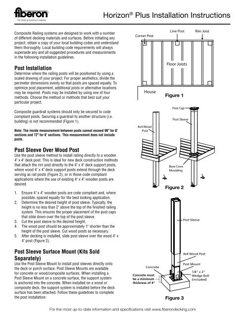
Composite Railing systems are designed to work with a number of different decking materials and surfaces. Before initiating any project, obtain a copy of your local building codes and understand them thoroughly. Local building code requirements will always supersede any and all suggested procedures and measurements in the following installation guidelines. Post Installation Determine where the railing posts will be positioned by using a scaled drawing of your project. For proper aesthetics, divide the perimeter dimensions evenly so that posts are spaced equally. To optimize post placement, additional joists or alternative locations may be required. Posts may be installed by using one of four methods. Choose the method or methods that best suit your particular project. Composite guardrail systems should only be secured to code compliant posts. Securing a guardrail to another structure (i.e. building) is not recommended (Figure 1). Note: The inside measurement between posts cannot exceed 96" for 8' sections and 72" for 6' sections. This measurement does not include posts. Post Sleeve Over Wood Post Use the post sleeve method to install railing directly to a wooden 4" x 4" deck post. This is ideal for new deck construction methods that attach the rim joist directly to the 4" x 4" deck support posts, where wood 4" x 4" deck support posts extend through the deck serving as rail posts (Figure 2), or in those code compliant applications where the use of existing 4" x 4" wooden posts are desired. 1. Ensure 4" x 4" wooden posts are code compliant and, where possible, spaced equally for the best looking application. 2. Determine the desired height of post sleeve. Typically, the height is no less than 2" above the top of the finished railing system. This ensures the proper placement of the post caps that slide down over the top of the post sleeve. 3. Cut the post sleeve to the desired height. 4. The wood post should be approximately 1" shorter than the height of the post sleeve. Cut wood posts as necessary. 5. After decking is installed, slide post sleeve over the wood 4" x 4" post (Figure 2). Post Sleeve Surface Mount (Kits Sold Separately) Use the Post Sleeve Mount to install post sleeves directly onto the deck or porch surface. Post Sleeve Mounts are available for concrete or wood/composite surfaces. When installing a Post Sleeve Mount on a concrete surface, the support system is anchored into the concrete. When installed on a wood or composite deck, the support system is installed before the deck surface has been attached. Follow these guidelines to complete the post installation: Horizon ® Plus Installation Instructions Concrete Concrete must be a minimum thickness of 4" Figure 1 Figure 2 Figure 3 Post Sleeve 4x4 Wood Post Post Mount For the most up-to-date information and specifications visit www.fiberondecking.com 1/4" x 3" Wedge Bolt (included)
- Page 2 and 3: For Concrete: (Fig 3) Concrete Must
- Page 4 and 5: attached. Holes have been provided
- Page 6 and 7: aluster slot in the top rail. Ensur
- Page 8: 27. Cut a crush block from a balust
Composite Railing systems are designed to work with a number<br />
of different decking materials and surfaces. Before initiating any<br />
project, obtain a copy of your local building codes and understand<br />
them thoroughly. Local building code requirements will always<br />
supersede any and all suggested procedures and measurements<br />
in the following installation guidelines.<br />
Post <strong>Installation</strong><br />
Determine where the railing posts will be positioned by using a<br />
scaled drawing of your project. For proper aesthetics, divide the<br />
perimeter dimensions evenly so that posts are spaced equally. To<br />
optimize post placement, additional joists or alternative locations<br />
may be required. Posts may be installed by using one of four<br />
methods. Choose the method or methods that best suit your<br />
particular project.<br />
Composite guardrail systems should only be secured to code<br />
compliant posts. Securing a guardrail to another structure (i.e.<br />
building) is not recommended (Figure 1).<br />
Note: The inside measurement between posts cannot exceed 96" for 8'<br />
sections and 72" for 6' sections. This measurement does not include<br />
posts.<br />
Post Sleeve Over Wood Post<br />
Use the post sleeve method to install railing directly to a wooden<br />
4" x 4" deck post. This is ideal for new deck construction methods<br />
that attach the rim joist directly to the 4" x 4" deck support posts,<br />
where wood 4" x 4" deck support posts extend through the deck<br />
serving as rail posts (Figure 2), or in those code compliant<br />
applications where the use of existing 4" x 4" wooden posts are<br />
desired.<br />
1. Ensure 4" x 4" wooden posts are code compliant and, where<br />
possible, spaced equally for the best looking application.<br />
2. Determine the desired height of post sleeve. Typically, the<br />
height is no less than 2" above the top of the finished railing<br />
system. This ensures the proper placement of the post caps<br />
that slide down over the top of the post sleeve.<br />
3. Cut the post sleeve to the desired height.<br />
4. The wood post should be approximately 1" shorter than the<br />
height of the post sleeve. Cut wood posts as necessary.<br />
5. After decking is installed, slide post sleeve over the wood 4" x<br />
4" post (Figure 2).<br />
Post Sleeve Surface Mount (Kits Sold<br />
Separately)<br />
Use the Post Sleeve Mount to install post sleeves directly onto<br />
the deck or porch surface. Post Sleeve Mounts are available<br />
for concrete or wood/composite surfaces. When installing a<br />
Post Sleeve Mount on a concrete surface, the support system<br />
is anchored into the concrete. When installed on a wood or<br />
composite deck, the support system is installed before the deck<br />
surface has been attached. Follow these guidelines to complete<br />
the post installation:<br />
Horizon ® <strong>Plus</strong> <strong>Installation</strong> <strong>Instructions</strong><br />
Concrete<br />
Concrete must<br />
be a minimum<br />
thickness of 4"<br />
Figure 1<br />
Figure 2<br />
Figure 3<br />
Post Sleeve<br />
4x4 Wood Post<br />
Post Mount<br />
For the most up-to-date information and specifications visit www.fiberondecking.com<br />
1/4" x 3"<br />
Wedge Bolt<br />
(included)
For Concrete: (Fig 3) Concrete Must Be a<br />
Minimum of 4" Thick.<br />
1. Determine the desired location(s) and finished height of the<br />
post sleeve from the deck surface.<br />
2. Trim the post sleeve to the desired length.<br />
3. Trim the length of the 4" x 4" wood post. The wood post<br />
length is typically 1-2”shorter than the post sleeve length.<br />
4. Use the base of the mount as a template and mark the four<br />
corner holes for the concrete Wedge-Bolt Anchors (Included<br />
in kit).<br />
5. Drill the marked holes using a ¼" masonry drill bit. Drill the<br />
holes into the concrete base to a depth of at least ½" deeper<br />
than the length of the ¼" x 3" Wedge Bolt Anchors. Blow the<br />
hole clean of dust and debris (Figure 4).<br />
6. Locate the mount by aligning the mount corner holes over<br />
the drilled holes.<br />
7. Insert the trimmed end of the 4" x 4" wood post into the<br />
mount. Ensure that the post in plumb and true.<br />
8. If necessary, place a shim under the mount to make the post<br />
plumb and true. To secure wood insert to surface mount<br />
bracket, use two #8 x 1 inch flat head screws (not included)<br />
(Figure 5).<br />
9. Insert the four concrete Wedge-Bolt Anchors into the corner<br />
holes of the mount. Begin tightening the Wedge-Bolt Anchor<br />
by rotating clockwise and applying pressure in toward the<br />
base. This will engage the first few threads as the Wedge-<br />
Bolt Anchor begins to advance. Continue to tighten until the<br />
head of the Wedge-Bolt Anchor is firmly seated against the<br />
post mount (Figure 6). Repeat for the remaining Wedge-Bolt<br />
Anchors.<br />
10. Slide the post sleeve over the 4" x 4" treated wood post until<br />
it contacts the base of the mount.<br />
For Wood:<br />
1. Determine the desired location(s) and finished height of the<br />
post sleeve from the deck surface.<br />
2. The thickness of the wood/composite deck and reinforcement<br />
boards underneath the deck should be a minimum of 4".<br />
(Two treated and structurally sound 2" x 8" lumber under the<br />
deck board, (Figure 9). Fasten the reinforcement boards with<br />
3" stainless steel fasteners as shown (Figure 7).<br />
3. Trim the post sleeve to the desired length.<br />
4. Trim the length of the 4" x 4" wood post. The wood post<br />
length is typically 1-2" shorter than the post sleeve length.<br />
5. Use the base of the mount as a template and mark the four<br />
corner holes on the deck surface. Mark inside square of<br />
bracket on deck surface.<br />
6. Drill four 3/8" holes at the marked locations, drilling<br />
through the deck board and the reinforcement boards.<br />
Drill 3/8" drainage hole in square through deck board and<br />
reinforcement boards for drainage.<br />
7. Locate the mount by aligning the mount corner holes over<br />
the drilled holes.<br />
8. Insert the trimmed end of the 4" x 4" wood post into the<br />
mount. Ensure that the post is plumb and true.<br />
Horizon ® <strong>Plus</strong> <strong>Installation</strong> <strong>Instructions</strong><br />
Figure 5 Figure 4 Figure 6<br />
4x4<br />
Wood Post<br />
Post Mount<br />
Deck Board<br />
5/16”<br />
Galvanized<br />
Nut (not included)<br />
Figure 7<br />
Figure 8<br />
Post Sleeve<br />
For the most up-to-date information and specifications visit www.fiberondecking.com<br />
5/16”x 5”<br />
Galvanized<br />
Bolt (included)<br />
5/16”<br />
Fender<br />
Washer<br />
(included)
9. If necessary, place a shim under the mount to make the post<br />
plumb and true. To secure wood insert to surface mount<br />
bracket, use two #8 x 1 inch flat head screws (not included)<br />
(Figure 5).<br />
10. Insert the 5/16" x 5" galvanized hex bolts into the mount holes<br />
and the drilled holes. (Galvanized bolts & nuts, not included)<br />
11. Fasten the four bolts underneath the reinforcement boards<br />
with the 5/16" Fender washer (included in kit) and 5/16"<br />
galvanized hex nuts (not included) (Figure 9).<br />
12. Slide the post sleeve over the 4" x 4" treated wood post until it<br />
contacts the base of the mount.<br />
Joist Mount Brackets (Sold Separately) for<br />
54" White Structural Post Only<br />
Use Joist Mount Brackets on projects where framing is fully<br />
exposed (Figure 1). In new construction, Joist Mount Brackets<br />
are attached to the inside of the framing before the porch flooring<br />
or decking is installed. Joist Mount Brackets may be used to<br />
install railing on existing decks provided the framing underneath<br />
is exposed to permit proper installation. Joist Mount Brackets<br />
can be used in a corner or line application and bolts directly to<br />
the framing with four galvanized carriage bolts. Follow these<br />
guidelines to complete the post installation:<br />
Note: When installing 8 foot sections in regions requiring 1999<br />
Standard Code compliance, the standard Joist Mount Bracket may NOT<br />
be used. Use either the Pro Joist Mount Bracket, the Surface Mount<br />
Bracket or the vinyl sleeve option. When in doubt, check with your<br />
local Building Inspections Department.<br />
1. Determine position of the posts on the framing (Figure 1).<br />
2. Position Joist Mount Bracket flush with top of framing at<br />
each post location (Figure 11).<br />
3. Use the Joist Mount Bracket as a template for hole location.<br />
With a pencil, mark hole positions on the framing.<br />
4. For corner posts, remove the side plate from the bracket<br />
(Figure 11). Mark hole positions on framing (Figure 12).<br />
5. Drill holes at desired locations using a 7/16" drill bit.<br />
6. Attach brackets to rim joists using four 3/8" x 3" galvanized<br />
carriage bolts (not included), washers and nuts. (At this<br />
point, do not fully tighten).<br />
7. Insert post into bracket until bottom of post contacts stop tab<br />
on bottom of bracket (Figure 13).<br />
8. Fully tighten carriage bolts and nuts to secure post in place.<br />
Ensure that post remains plumb.<br />
Surface Mount Brackets (Kits Sold<br />
Separately) for 54" White Structural Post<br />
Only.<br />
Use the Surface Mount Brackets to install posts directly onto<br />
the deck or porch surface. Surface Mount Brackets are available<br />
for concrete or wood/composite surfaces. When installing a<br />
post on a concrete surface, the support system is anchored<br />
into the concrete. When installed on a wood or composite deck,<br />
the support system is installed after the deck surface has been<br />
Horizon ® <strong>Plus</strong> <strong>Installation</strong> <strong>Instructions</strong><br />
Decking<br />
2x8<br />
2x8<br />
3/8” x 3”<br />
carriage<br />
bolt,<br />
nut &<br />
washer<br />
Concrete<br />
must be<br />
a minimum<br />
thickness<br />
of 4”<br />
Figure 9<br />
Top of Joist<br />
Corner post bracket<br />
Figure 11<br />
Figure 12 Figure 13<br />
Figure 14<br />
Figure 15<br />
For the most up-to-date information and specifications visit www.fiberondecking.com<br />
Figure 16
attached. Holes have been provided in the bracket to aid guardrail<br />
installation. Care should be taken to orient holes as line, end, or<br />
corner. Follow these guidelines to complete the post installation:<br />
For Concrete: (Figure 16) Concrete Must Be a<br />
Minimum of 4" Thick<br />
1. Lay out the locations for the posts.<br />
2. Use the base plate as a template and mark the four corner<br />
holes for the concrete Wedge-Bolt Anchors.<br />
3. Drill the marked holes using a 1/4" masonry drill bit. Drill the<br />
hole into the concrete base to a depth of at least 1/2" deeper<br />
than the length of the 1/4" x 3" Wedge-Bolt Anchors. Blow the<br />
hole clean of dust and debris (Figure 14).<br />
4. Align the base plate over the drilled holes.<br />
5. Position the post mount over the top of the base plate.<br />
6. Screw the 5/16" leveling set screws into the four tapped<br />
holes. If needed, adjust the set screws to straighten the post.<br />
7. Insert the four concrete Wedge-Bolt Anchors into holes<br />
located on the corners of the bottom plate. Begin tightening<br />
the Wedge-Bolt Anchors by rotating clockwise and applying<br />
pressure in toward the base. This will engage the first few<br />
threads as the Wedge-Bolt Anchors begin to advance.<br />
Continue to tighten until the head of the Wedge-Bolt Anchor<br />
is firmly seated against the post mount (Figure 15).<br />
8. Slide the composite structural post over the post mount until<br />
it contacts the concrete. The post sizing stabilizers will secure<br />
the composite post in proper position.<br />
For Wood: (Figure 17 - Corner, Figure 19 -<br />
Line)<br />
1. Lay out the locations for the posts.<br />
2. Thickness of wood/composite deck and reinforcement boards<br />
underneath deck should be a minimum of 4". (Two treated<br />
2" x 8" lumber under the deck board). Fasten reinforcement<br />
boards with 3" stainless steel fasteners as shown (Figure 7).<br />
3. Use post mount as a template and mark the four corner holes<br />
for the 5/16" x 5-1/2" bolts.<br />
4. Drill four 3/8" holes at the marked locations, drilling through<br />
the deck board and the reinforcement boards.<br />
5. Align the base plate over the drilled holes as shown at left.<br />
6. Screw the 5/16" leveling set screws into the four tapped<br />
holes. If needed, adjust the set screws to straighten the post.<br />
7. Insert the four 5/16" x 5-1/2" bolts into the drilled 3/8" holes.<br />
8. Fasten the four bolts underneath the second base plate with<br />
the 5/16" Fender washer and hex nut.<br />
9. Slide composite structural post over the post mount until it<br />
contacts the base plate. The post sizing stabilizers will secure<br />
the post in proper position.<br />
Horizon ® <strong>Plus</strong> <strong>Installation</strong> <strong>Instructions</strong><br />
Joist<br />
5/16”<br />
Fender<br />
Washer<br />
Decking<br />
2x8<br />
2x8<br />
Figure 17<br />
Figure 18<br />
Under deck<br />
reinforcement<br />
2"x 8" (minimum)<br />
treated lumber<br />
Figure 19<br />
For the most up-to-date information and specifications visit www.fiberondecking.com<br />
Line<br />
Application<br />
Joist
Line Rail <strong>Installation</strong><br />
1. Measure the distance between properly installed, plumb<br />
posts.<br />
2. Mark the top rail for the inside distance between the posts.<br />
The distance from the end of the rail to the first baluster slots<br />
should be equal on both ends of the rail. Ensure that the<br />
bracket screws will fasten into the top rail and that none fall<br />
into the routed baluster slots.<br />
Note: Minimum distance from post to first baluster slot on top rail is 2<br />
1/8".<br />
3. Place the bottom rail next to the top rail so that the top and<br />
bottom baluster slots are aligned. Mark the bottom rail for the<br />
inside distance between the posts.<br />
4. Cut the top and bottom rails to fit tightly between the posts.<br />
5. Center the bottom bracket on the underside of the bottom rail<br />
(Figure 20). Inset the bottom bracket 1/16" from the end of<br />
the rail. Mark the three hole locations on the rail. Predrill 1/8"<br />
holes at the desired locations. Repeat for opposite end.<br />
6. Secure the bottom bracket to the bottom rail using three #10<br />
x 3/4" long screws. Repeat for opposite end. DO NOT OVER-<br />
TIGHTEN SCREWS.<br />
7. Center the top bracket on the underside of the top rail (Figure<br />
21). Inset the top bracket 1/16" from the end of the rail. Mark<br />
the three hole locations on the rail. Predrill 5/32" holes at the<br />
desired locations. Repeat for opposite end.<br />
8. Secure the top bracket to the top rail using three #12 x<br />
1" long screws. Repeat for opposite end. DO NOT OVER-<br />
TIGHTEN SCREWS.<br />
9. Ensure that the base cove moulding is in place at the bottom<br />
of the posts (Figure 2).<br />
10. Place crush block on the deck surface midway between the<br />
posts (Figure 25).<br />
11. Place the bottom rail between the posts and on the crush<br />
block. Ensure that the bottom rail is level and that the ends of<br />
the rail are centered on the post.<br />
12. Mark on the post the two bottom bracket hole locations.<br />
Predrill 1/8" holes at desired locations. Repeat for opposite<br />
end.<br />
13. Secure the bottom rail to the post using two #10 x 2" long<br />
screws. Repeat for opposite end. DO NOT OVER-TIGHTEN<br />
SCREWS.<br />
Note: A flexible shaft bit holder (not included) is helpful during this<br />
step.<br />
14. Determine the desired baluster design (squared look,<br />
diamond look or a mixed pattern of the two. Diamond pattern<br />
not possible on stair sections) (Figure 22).<br />
15. Ensure that all of the balusters are of equal length. Trim if<br />
necessary.<br />
16. Fully engage the bottom baluster insert (Figure 23) into each<br />
baluster slot in the bottom rail. Orient the bottom baluster<br />
insert to achieve the desired look (Figure 22).<br />
17. Fully engage a baluster over each bottom baluster insert.<br />
18. Fully engage the top baluster insert (Figure 24) into each<br />
Horizon ® <strong>Plus</strong> <strong>Installation</strong> <strong>Instructions</strong><br />
Mission Top Rail<br />
Square<br />
pattern<br />
Bottom Rail<br />
Figure 20<br />
Figure 21<br />
Figure 22<br />
#12 Top Rail Screw<br />
For the most up-to-date information and specifications visit www.fiberondecking.com<br />
Bottom<br />
Bracket<br />
#10 Bottom Rail Screw<br />
Top<br />
Bracket<br />
Diamond<br />
pattern<br />
3/4”<br />
2”<br />
1”<br />
2”
aluster slot in the top rail. Ensure that the top baluster insert<br />
is oriented the same as the corresponding bottom baluster<br />
insert.<br />
19. Place the top rail between the post and above the top end of<br />
the balusters. Starting at one end of the rail, reposition top<br />
end of the baluster to allow the top baluster insert to engage<br />
it. Repeat for each baluster.<br />
20. Once all of the balusters are engaged, gently push down on<br />
the top rail until the bottom end of the balusters contacts the<br />
bottom rail (Figure 25). The flange of the top baluster insert<br />
should be tightly secured between baluster and the underside<br />
of the top rail.<br />
21. Ensure that the top rail is level and that the rail ends are<br />
centered on each post.<br />
22. Mark on the post the two top bracket hole locations. Predrill<br />
5/32" holes at the desired locations. Repeat for opposite end.<br />
23. Secure the top rail to the post using two #12 x 2" long<br />
screws. Repeat for opposite end. DO NOT OVER-TIGHTEN.<br />
Note: A flexible shaft bit holder (not included) is helpful during this<br />
step.<br />
24. Secure crush block support with supplied screw to mid-point<br />
of underside of bottom rail.<br />
25. Mount and glue post caps after all rail section are installed.<br />
Stair Rail <strong>Installation</strong> (Requires Stair Rail<br />
Kit)<br />
Note: The stair angle is a 32 degree angle which is equal to a 7" rise<br />
and an 11" run. Building codes are very specific on allowable angles<br />
and widths. It is very important to consult with your local building code<br />
officials and plan your stair layout accordingly. Ensure that you leave<br />
adequate space for graspable hand rail if applicable. “Dry fitting”<br />
intermediate post placement will result in easier and better looking<br />
installations and may avoid placement of post mounting brackets in<br />
areas where screws cannot attach to the guardrail.<br />
1. Position two line posts at top of stairway with the desired<br />
spacing and secure each post with the appropriate installation<br />
method (Figure 26).<br />
2. Install the outside stringers just wider than the post’s<br />
location. The posts mounted at the bottom of the stairs will<br />
be on the inside of the stringer and must line up directly with<br />
the posts at the top of the stairs.<br />
Note: For stairs longer than 6', it will be necessary to use multiple<br />
stair sections. The distance between posts, measured at an angle<br />
should not exceed 70". Ensure all posts are plumb prior to final<br />
mounting. Minimum distance from post to first baluster slot on top rail<br />
is 2 7/8".<br />
3. Lay bottom rail on stair with marked end at lower post.<br />
Center the rail between the posts so that the distance from<br />
the post to the first routed hole is equal on both ends. (Figure<br />
27).<br />
4. Mark angles on the bottom rail.<br />
Horizon ® <strong>Plus</strong> <strong>Installation</strong> <strong>Instructions</strong><br />
Top<br />
baluster<br />
insert<br />
Bottom<br />
baluster<br />
insert<br />
Figure 23<br />
Figure 24<br />
Base Cove Moulding<br />
Figure 25<br />
Figure 26<br />
Crush Block<br />
For the most up-to-date information and specifications visit www.fiberondecking.com
Rim Joists<br />
Stringers<br />
5. Cut the bottom rail to length. Ensure that the rail fits tightly<br />
between the posts.<br />
6. Place the top rail next to the bottom rail with the marked ends<br />
together. Using the bottom rail as a guide, center the routed<br />
holes in the top rail with the routed holes in the bottom rail.<br />
Mark the cut lines on the top rail (Figure 28).<br />
7. Cut the top rail to length.<br />
8. Ensure that the base cove moulding is in place at the bottom<br />
of the posts (Figure 29).<br />
9. Center the hinged bracket on the underside of the bottom rail.<br />
Inset the hinged bracket 1/16" from the end of the rail. Mark<br />
the three bracket hole locations on the rail. Predrill 5/32" hole<br />
at the desired locations. Repeat for opposite end.<br />
10. Secure the hinged bracket to the bottom rail using three #12<br />
x 1" long screws. Repeat for opposite end. DO NOT OVER-<br />
TIGHTEN SCREWS.<br />
Note: For easier access to securing the fasteners in a stair assembly, a hinge<br />
bracket with side wings (currently used for securing the top rail) may be<br />
substituted for the bottom hinge bracket without the side wings.<br />
11. Repeat steps 9-10 for the top rail.<br />
12. Lay the bottom rail, with the routed holes upward, onto a<br />
1/4" wood spacer located between the posts (Figure 29). This<br />
provides the rail spacing between the rail and stair treads and<br />
helps to stabilize the setup.<br />
13. Using the hinged bracket as a template, swing the unsecured<br />
leg of the bracket downward so that it touches the post. Mark<br />
the two hole locations on the post. Repeat for opposite end.<br />
14. Remove the bottom rail from between the posts.<br />
15. Predrill 5/32" holes at desired bracket hole locations.<br />
16. Place bottom rail between the posts. Secure the bottom<br />
rail to the post using two #12 x 2" long screws. Repeat for<br />
opposite end. DO NOT OVER-TIGHTEN.<br />
17. Fully engage the baluster inserts into the routed holes of the<br />
bottom rail (Figure 30).<br />
18. Mark the stair angle on one end of each baluster to be used<br />
(Figure 29).<br />
19. Cut the composite square baluster at an angle on the top and<br />
bottom of each baluster (Figure 29).<br />
20. Fully insert the top ends of the balusters into the routed<br />
holes of the top rail. The angled cut of the baluster should be<br />
parallel with the length of the top rail. (Figure 29).<br />
21. Place the top rail and balusters on top of the baluster inserts.<br />
Locate each baluster so that the baluster insert is engaged<br />
inside of the baluster.<br />
22. Gently push down on the top rail until the bottom end of the<br />
balusters contacts the bottom rail.<br />
23. Ensure that the top rail ends are centered on each post.<br />
24. Using the hinged bracket as a template, swing the unsecured<br />
leg of the bracket downward so that it touches the post. Mark<br />
the two hole locations on the post. Repeat for opposite end.<br />
25. Slightly pull the top of the rail section toward the staircase to<br />
gain access to holes. Predrill 5/32" holes at desired locations.<br />
Repeat for opposite end.<br />
26. Secure top rail to post using two #12 x 2" long screws.<br />
Repeat for opposite end. DO NOT OVER-TIGHTEN SCREWS.<br />
Horizon ® <strong>Plus</strong> <strong>Installation</strong> <strong>Instructions</strong><br />
Figure 27<br />
Cut Line<br />
Figure 28<br />
Figure 29<br />
Crush Block<br />
For the most up-to-date information and specifications visit www.fiberondecking.com<br />
Top<br />
Bottom
27. Cut a crush block from a baluster to the desired height.<br />
(Consult local building official for the proper spacing between<br />
the deck and the railing). Place crush block on the stair tread<br />
surface midway between the posts (Figure 29).<br />
Angle Rail <strong>Installation</strong> (Angle Bracket Kit<br />
Available by Special Order)<br />
Rails up to 20 degrees may be mounted to the post face by using<br />
the In Line “L” Bracket (Figure 20). Rails should be cut at the<br />
appropriate angle to fit tight against post. Cutting rails greater<br />
than 20 degrees will result in a rail that does not fully fit on post.<br />
Angles greater than 20 degrees require the use of the Angle<br />
Mount Bracket.<br />
Note: Minimum distance from post corner to first baluster hole 2 1/4".<br />
1. Determine the angle of your installation by using the supplied<br />
template (located on the last page of this booklet).<br />
2. Cut the template out along the appropriate marked lines. (You<br />
may want to photocopy the template as a backup prior to<br />
cutting).<br />
3. Position the template on the non-routed flat side of the top<br />
rail. Mark the proper cutting angle (Figure 31).<br />
4. Position the template on the non-routed bottom surface of<br />
the bottom rail (Figure 31). Mark the proper cutting angle.<br />
Template will be reversed from top rail.<br />
5. Ensure baluster holes are equidistant from the end of rail to<br />
ensure proper vertical alignment.<br />
6. Make angle cuts in top and bottom rails.<br />
7. Align the angled brackets with the 90 degree cut in the railing.<br />
Inset the bracket 1/16" from rails end. Mark the three screw<br />
hole locations on both rails. Repeat at opposite end. Predrill<br />
1/8" holes at desired locations (Figure 32).<br />
8. After fitting angles to posts, follow the line rail instructions<br />
(Steps 6 through 22) to complete the rail section installation.<br />
45<br />
40<br />
35<br />
30<br />
25<br />
20<br />
ANGLE RAIL CUTTING TEMPLATE<br />
20<br />
25<br />
30<br />
35<br />
40<br />
45<br />
Horizon ® <strong>Plus</strong> <strong>Installation</strong> <strong>Instructions</strong><br />
Top Rail<br />
Bottom Rail<br />
Figure 30<br />
Figure 31<br />
Figure 32<br />
For the most up-to-date information and specifications visit www.fiberondecking.com<br />
FIB-0101-LIT 5/11


