Marea- Marea Weekend Summary
Marea- Marea Weekend Summary
Marea- Marea Weekend Summary

Create successful ePaper yourself
Turn your PDF publications into a flip-book with our unique Google optimized e-Paper software.
<strong>Marea</strong>- <strong>Marea</strong> <strong>Weekend</strong> <strong>Summary</strong><br />
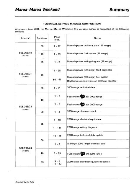
TECHNICAL SERVICE MANUAL COMPOSITION<br />
At present, June 2001, the <strong>Marea</strong>-<strong>Marea</strong> <strong>Weekend</strong> 4th volume manual is composed of the following<br />
sections<br />
Print N° Sections<br />
506.763/18<br />
(XI/1999)<br />
506.763/21<br />
(IX/2000)<br />
506.763/23<br />
(IX/2000)<br />
506.763/24<br />
(XII/2000)<br />
Copyright by Fiat Auto<br />
Page<br />
Nos.<br />
Notes<br />
00 1 - 12 <strong>Marea</strong> bipower technical data (99 range)<br />
10 1 - 59 <strong>Marea</strong> bipower fuel system (99 range)<br />
55 1 - 2 <strong>Marea</strong> bipower wiring diagram (99 range)<br />
10<br />
1 - 38<br />
60 - 61<br />
<strong>Marea</strong> bipower (99 range) fault diagnosis<br />
<strong>Marea</strong> bipower (99 range) fuel system<br />
Replacing solenoid valve on methane canister<br />
00 1 - 51 2000 range technical data<br />
10<br />
1 - 7 Fuel system l^pl i6v 2000 range<br />
1 - 7 Fuel system l^pt 20v 2000 range<br />
50 1 - 4 2000 range climate control<br />
55<br />
00<br />
1 - 18<br />
1 - 141<br />
15 - 16<br />
1 - 3<br />
2000 range electrical equipment<br />
2000 range wiring diagrams<br />
2000 range technical data update<br />
Marengo 2000 range technical data<br />
10 1 - 29 Fuel system l^p) JTD 2000 range<br />
55<br />
5 - 8<br />
19-52<br />
2000 range electrical equipment update
<strong>Summary</strong> <strong>Marea</strong>- <strong>Marea</strong> <strong>Weekend</strong><br />
Print N° Sections<br />
506.763/24<br />
(XI1/2000)<br />
506.763/25<br />
VI/2001)<br />
55<br />
Page<br />
Nos.<br />
Index<br />
11-14<br />
27 - 28<br />
47 - 48<br />
83 - 88<br />
99 - 100<br />
103 - 104<br />
00 1 - 2<br />
10<br />
5 - 6<br />
25 - 26<br />
29 - 37<br />
Notes<br />
2000 range wiring diagrams update<br />
<strong>Marea</strong> <strong>Weekend</strong> 1910 JTD - 100 CV Introduction -<br />
Technical data<br />
1910 JTD 2000 range fuel system update<br />
Print n° 506.763/25
<strong>Marea</strong> - <strong>Marea</strong> <strong>Weekend</strong> <strong>Summary</strong><br />
TECHNICAL SERVICE MANUAL COMPOSITION<br />
As of December 2000, the <strong>Marea</strong>-<strong>Marea</strong> <strong>Weekend</strong> 4th volume manual is composed of the sections<br />
listed below<br />
Print N° Sections<br />
506.763/18<br />
(XI/1999)<br />
506.763/20<br />
(IV/2000)<br />
506.763/21<br />
(IX/2000)<br />
506.763/23<br />
(IX/2000)<br />
Copyright by Fiat Auto<br />
Page<br />
Nos.<br />
Notes<br />
00 1 - 12 <strong>Marea</strong> bipower technical data (99 range)<br />
10 1 - 59 <strong>Marea</strong> bipower fuel system (99 range)<br />
55 1 - 2 <strong>Marea</strong> bipower wiring diagram (99 range)<br />
00 1 - 15 <strong>Marea</strong> GPL technical data<br />
10 1 - 26 <strong>Marea</strong> GPL fuel system<br />
55 1 - 9 <strong>Marea</strong> GPL wiring diagram<br />
10<br />
1 - 38 <strong>Marea</strong> bipower fault diagnosis (99 range)<br />
60 - 61<br />
<strong>Marea</strong> bipower fuel system (99 range)<br />
Replacing solenoid on methane canister<br />
00 1 - 50 2000 range technical data<br />
10<br />
1 - 7<br />
1 - 7<br />
2000 range lev fuel system<br />
2000 range ^||) 20v fuel system<br />
50 1-4 2000 range climate control system<br />
55<br />
1 - 18 2000 range electrical equipment<br />
1 - 141 2000 range wiring diagrams
<strong>Summary</strong> <strong>Marea</strong>-<strong>Marea</strong> <strong>Weekend</strong><br />
506.763/24<br />
(XII/2000)<br />
00<br />
15 - 16 2000 range technical data update<br />
1 - 3 2000 range Marengo technical data<br />
10 1 - 29 Fuel system l|pl m> 2000 range<br />
55<br />
5 -8<br />
19 -52<br />
Contents<br />
11 - 14<br />
27 - 28<br />
47 - 48<br />
83 - 88<br />
99 - 100<br />
103 - 104<br />
Updated 2000 range electrical equipment<br />
Update to wiring diagrams - 2000 range<br />
Publication no. 506.763/24
<strong>Marea</strong>- <strong>Marea</strong> <strong>Weekend</strong> <strong>Summary</strong><br />
TECHNICAL SERVICE MANUAL COMPOSITION<br />
At present, September 2000, the <strong>Marea</strong>-<strong>Marea</strong> <strong>Weekend</strong> 4th volume manual is composed of the following<br />
booklets<br />
Print N° Sections<br />
506.763/18<br />
(XI/1999)<br />
506.763/20<br />
(IV/2000)<br />
506.763/21<br />
(IX/2000)<br />
506.763/23<br />
(IX/2000)<br />
Copyright by Fiat Auto<br />
Page<br />
Nos.<br />
Notes<br />
00 1 - 12 Technical data on <strong>Marea</strong> bipower (99 range)<br />
10 1 - 59 <strong>Marea</strong> bipower fuel system (99 range)<br />
55 1 - 2<br />
<strong>Marea</strong> bipower electrical equipment wiring diagrams (99<br />
range)<br />
00 1 - 15 <strong>Marea</strong> GPL technical data<br />
10 1 - 26 <strong>Marea</strong> GPL fuel system<br />
55 1 - 9 <strong>Marea</strong> GPL electrical equipment wiring diagram<br />
10<br />
1 - 38<br />
60 - 61<br />
<strong>Marea</strong> bipower fault diagnosis (99 range)<br />
<strong>Marea</strong> bipower fuel system (99 range)<br />
Replacing solenoid valve on methane canister<br />
00 1 - 50 Technical data 2000 range<br />
10<br />
1 - 7 Fuel system @> 1 6 v 2000 range<br />
1 - 7 Fuel system l^l 20v 2000 range<br />
50 1 - 4 Climate control system 2000 range<br />
55<br />
1 - 18<br />
1 - 141<br />
Electrical equipment 2000 range<br />
Electrical equipment wiring diagrams 2000 range
m a r e a - m a r e a v v v t t n v i i u miruuuCuuu ciilu iwnniCai data<br />
2000 range © Index<br />
00.<br />
Copyright by Fiat Auto<br />
1<br />
INTRODUCTION<br />
page<br />
- Identification data 1<br />
- Weights 3<br />
- Performance - Fuel consumption 4<br />
- Dimensions 5<br />
- Capacities 7<br />
- Product specifications<br />
FL Group 9<br />
TECHNICAL DATA<br />
Engine l^^) lev |^^) 20v<br />
- Specifications 10<br />
- Typical curves 11<br />
- Cylinder block/crankcase and associated<br />
components 12<br />
- Auxiliary shaft 17<br />
- Cylinder head and valve gear components<br />
18<br />
- Timing diagrams 22<br />
- Counter-balance shaft 23<br />
- Lubrication 24<br />
- Cooling system 26<br />
- Fuel feed system 26<br />
- Special tools 27<br />
Engine I^^JJTD<br />
- Specifications 29<br />
- Timing diagrams 30<br />
- Supercharging 31<br />
CLUTCH 32<br />
GEARBOX AND DIFFERENTIAL 33<br />
AUTOMATIC TRANSMISSION DIF<br />
FERENTIAL 35<br />
BRAKING SYSTEM 36<br />
STEERING 39<br />
WHEELS 40<br />
FRONT SUSPENSION 42<br />
REAR SUSPENSION 44<br />
ELECTRICAL EQUIPMENT 46<br />
- Ignition 47<br />
- Recharging 48<br />
- Electronic injection/ignition 50
<strong>Marea</strong>-<strong>Marea</strong> <strong>Weekend</strong> Introduction<br />
2000 range (§) Identification data<br />
OO.o<br />
NOTE<br />
CHASSIS ENGINE VERSION MAREA<br />
ZFA 185 000<br />
182B6.000<br />
185A8.000<br />
186A6.000<br />
185AXR1A 25<br />
185BXR1A 26<br />
185AXR11 27<br />
185BXR11 28 •<br />
185AXS1A29<br />
185BXS1A30<br />
185AXT1A 31<br />
185BXT1A 32 •<br />
•<br />
•<br />
•<br />
•<br />
GEARBOX<br />
MAREA<br />
WEEKEND 999<br />
666<br />
This section deals with the EEC F3 2000 range engine types.<br />
For the subjects not dealt with, refer to the <strong>Marea</strong>-<strong>Marea</strong> <strong>Weekend</strong> manual print n° 506.763 and subsequent<br />
updates.<br />
Copyright by Fiat Auto 1<br />
•<br />
•<br />
•<br />
•<br />
•<br />
•
Introduction<br />
Identification data<br />
I<br />
o<br />
N<br />
kg<br />
F ] kg<br />
1- G ] kg<br />
2- [ kg<br />
M0TORE- ENGINE<br />
VERSIONE-VERSION<br />
N 2<br />
PER RICAMBI<br />
N 8<br />
FOR SPARES<br />
M<br />
o<br />
Matea- <strong>Marea</strong> <strong>Weekend</strong><br />
2000 range @)<br />
A. Vehicle type identification code and chassis<br />
number<br />
B. V.I.N. Plate (EEC regulations)<br />
C. Engine type and number.<br />
A. Manufacturer's name<br />
B. Homologation number<br />
C. Vehicle type identification code<br />
D. Chassis manufacture number<br />
E. Maximum authorised vehicle weight when<br />
fully laden<br />
F. Maximum authorised weight of fully laden<br />
vehicle plus trailer<br />
G. Maximum authorised weight on first axle<br />
(front)<br />
H. Maximum authorised weight on second axle<br />
(rear)<br />
I. Engine type<br />
L. Body version code<br />
M. Spares number<br />
N. Correct value of smoke absorption coefficient<br />
(for Diesel engines only)<br />
2 Print n° 506.763/23
<strong>Marea</strong>- <strong>Marea</strong> <strong>Weekend</strong><br />
2000 range @<br />
Permissible loads on the axles<br />
+590=<br />
(575)'<br />
ENGINE TYPE<br />
+595=<br />
(580)*<br />
¥¥¥¥¥<br />
mrirnT<br />
<strong>Marea</strong><br />
<strong>Marea</strong> <strong>Weekend</strong><br />
<strong>Marea</strong><br />
<strong>Marea</strong> <strong>Weekend</strong><br />
16v 20v<br />
1140<br />
1165 (•)<br />
1200<br />
1225 (•)<br />
1730<br />
1755 (T)<br />
1795<br />
1820 (T)<br />
Introduction<br />
Weights<br />
OO.o<br />
1255<br />
1315<br />
1830<br />
1895<br />
1000 1000<br />
1000 1000<br />
Maximum permitted load on roof 80 80<br />
Load on tow hook ball<br />
(trailer with braking system)<br />
I Loads that should never be exceeded<br />
(*) Specific figures for 1998 20v version<br />
(•) Specific figures for the <strong>Marea</strong> <strong>Weekend</strong><br />
(T) Specific figures for the 1596 16v automatic transmission version<br />
Without braking<br />
system<br />
With braking<br />
system<br />
70 70<br />
400 400<br />
1200<br />
1300<br />
(1400)«<br />
NOTE FOR VERSIONS WITH ACCESSORIES: In the presence of special equipment (non standard air conditioning, sun<br />
roof, trailer towing device, etc.), the empty weight increases and therefore the carrying capacity may decrease in relation to<br />
the maximum permissible loads.<br />
Copyright by Fiat Auto 3
Introduction<br />
Performance - Fuel consumption<br />
OO.o<br />
(*) For <strong>Marea</strong> <strong>Weekend</strong><br />
Speed km/h (half laden)<br />
Max. climable<br />
gradient<br />
fully laden<br />
Urban<br />
Out-of-town<br />
Fuel consumption in accordance<br />
with directive<br />
1999/100/CE (litres/100 km) Combined<br />
CO2 exhaust emissions (g/km)<br />
ENGINE TYPE<br />
<strong>Marea</strong>-<strong>Marea</strong> <strong>Weekend</strong><br />
2000 range ©<br />
16v 16v C.A 20v JTD<br />
46<br />
80<br />
124<br />
173<br />
187<br />
(185)'<br />
46<br />
MAX<br />
187<br />
(185)*<br />
59<br />
94<br />
139<br />
182<br />
208<br />
(206)*<br />
54<br />
<strong>Marea</strong> 36 32 39<br />
<strong>Marea</strong> <strong>Weekend</strong> 33 30 36<br />
<strong>Marea</strong> 11.2 12.2 13.7<br />
<strong>Marea</strong> <strong>Weekend</strong> 11.3 12.4 13.8<br />
<strong>Marea</strong> 6.3 6.7 7.6<br />
<strong>Marea</strong> <strong>Weekend</strong> 6.5 6.7 7.7<br />
<strong>Marea</strong> 8.1 8.7 9.8<br />
<strong>Marea</strong> <strong>Weekend</strong> 8.2 8.8 9.9<br />
<strong>Marea</strong> 192 207 234<br />
<strong>Marea</strong> <strong>Weekend</strong> 195 210 237<br />
The fuel consumption figures in accordance with directive 1999/100/CE have been defined during the course of homologation<br />
tests which include:<br />
- An urban cycle which includes a cold start followed by a simulated varied urban cycle.<br />
- A non-urban cycle which includes frequent acceleration in all gears simulating normal out-of-town use of the vehicle.<br />
The speed varies between 0 and 120 km/h.<br />
- The average combined consumption includes 37% urban cycle and 63% non-urban cycle.<br />
The type of route, traffic conditions, driving style, weather conditions, trim level/equipment/accessories, presence of special<br />
equipment and the state of the vehicle in general can lead to different fuel consumption figures from those established<br />
using the above mentioned procedures.<br />
The CO2 exhaust emissions (in g/km) are measured during the average combined cycle.<br />
4 Print n° 506.763/23
<strong>Marea</strong> Introduction<br />
2000 range @ Dimensions<br />
OO.o<br />
Luggage compartment capacity (VDA regulations): 430 dm 3<br />
The height refers to an unladen vehicle<br />
Engine types Wheel rim A B c D E F G H<br />
5 1<br />
/ 2Jx14-43<br />
6Jx15-43<br />
5!4Jx14-43<br />
6Jx15-43<br />
884 2540 969 4393<br />
884 2540 969 4393<br />
1470<br />
1470<br />
1470<br />
1470<br />
1440<br />
1440<br />
1440<br />
1440<br />
F<br />
1741 1425<br />
1741 1425<br />
6Jx15-49 884 2540 969 4393 1475 1430 1741 1428<br />
5 1<br />
/ 2Jx14-43<br />
6Jx15-43<br />
884 2540 969 4393<br />
1470<br />
1470<br />
1440<br />
1440<br />
1741 1425<br />
Copyright by Fiat Auto 5
Introduction<br />
Dimensions<br />
OO.o<br />
Luggage compartment capacity with vehicle unladen (V.D.A. standards): 500 dm 3<br />
(1540 dm 3<br />
with seats folded)<br />
<strong>Marea</strong> <strong>Weekend</strong><br />
2000 range @)<br />
Engine types Wheel rim A B C D E F G H<br />
5Y 2Jx14-43<br />
6Jx15-43<br />
5%Jx14-43<br />
6Jx15-43<br />
884 2540 1066 4490<br />
884 2540 1066 4490<br />
1470<br />
1470<br />
1470<br />
1470<br />
1440<br />
1440<br />
1440<br />
1440<br />
1741 1510<br />
1741 1510<br />
ifipl 20 v 6Jx15-49 884 2540 1066 4490 1475 1435 1741 1510<br />
5 1<br />
/ 2Jx14-43<br />
6Jx15-43<br />
884 2540 1066 4490<br />
1470<br />
1470<br />
1440<br />
1440<br />
1741 1510<br />
6 Print rf 506.763/23
<strong>Marea</strong>- <strong>Marea</strong> <strong>Weekend</strong> Introduction<br />
2000 range (§) Capacities<br />
OO.o<br />
^ft diesel<br />
Product Parts to be filled<br />
Petrol > O.R. 95<br />
Unleaded<br />
50% p n<br />
50% p n<br />
TP<br />
i •' • • i r - F I -<br />
Total capacity of cooling<br />
system<br />
dm 3<br />
(I)<br />
•<br />
•<br />
Kg<br />
16v 20v JTD<br />
63 63 -<br />
- - 63<br />
7<br />
(6.7 •)<br />
7.6<br />
(7.4 •)<br />
6<br />
(5.6 •)<br />
Petrol engines<br />
• 4.5 5.5 4.8<br />
SELENIA 20K<br />
(SAE 10W/40) (•)<br />
• 4 4.7 4.25<br />
g|l Diesel Engines:<br />
SELENIA TURBO<br />
DIESEL<br />
(SAE 10W/40) (••)<br />
Total capacity<br />
m-m<br />
Partial capacity<br />
(scheduled changes)<br />
•<br />
•<br />
3.8<br />
(3.5*)<br />
3.4<br />
(3.1*)<br />
5<br />
(4.5*)<br />
4.45<br />
(4*)<br />
4.3<br />
(4*)<br />
3.75<br />
(3.55*)<br />
TUTELACAR<br />
ZC 75 Synth<br />
frQQ<br />
•<br />
•<br />
1.98<br />
1.8<br />
1.98<br />
1.8<br />
1.65<br />
1.5<br />
(•) Distilled water<br />
• 4.3 - -<br />
TUTELA *<br />
GI/2 -J» • 3.9 - -<br />
(•) For versions with air conditioning<br />
(*) Engine sump only<br />
(•) For temperatures below -20°C the use of SELENIA PERFORMER SAE 5W-30 is recommended<br />
(••) For temperatures below -15°C the use of SELENIA WR DIESEL 5W-40 is recommended<br />
Copyright by Fiat Auto<br />
7
Introduction <strong>Marea</strong>-<strong>Marea</strong> <strong>Weekend</strong><br />
Capacities 2000 range ©<br />
00.0<br />
Product Parts to be filled<br />
TUTELA<br />
HI Gl/A<br />
TUTELA<br />
• • MRM2<br />
TUTELA<br />
r H top4<br />
* +<br />
* +<br />
* +<br />
* +<br />
Total capacity<br />
30%<br />
- 10°C 50% I<br />
d +<br />
- 20°C 100% J<br />
without<br />
ABS<br />
with<br />
ABS<br />
s?><br />
Quantity<br />
dm 3<br />
(I) Kg<br />
- 0.8<br />
- 0.003<br />
0.40 -<br />
0.45 -<br />
5 -<br />
6.8 -<br />
8 Print n° 506.763/23
<strong>Marea</strong>-<strong>Marea</strong> <strong>Weekend</strong><br />
2000 range (§)<br />
Name of<br />
product<br />
SELENIA 20K<br />
SELENIA<br />
PERFORMER<br />
SELENIA<br />
Turbo Diesel<br />
SELENIA<br />
WR DIESEL<br />
TUTELA CAR<br />
ZC 75 SYNTH<br />
TUTELA Gl/A<br />
TUTELA GI/2<br />
TUTELA MRM2<br />
TUTELA TOP 4<br />
DP1<br />
Paraflu 11<br />
Diesel Mix<br />
Description<br />
International designation<br />
Synthetic SAE 10W40 multigrade engine oil.<br />
Exceeds specifications ACEA A3-96/CCMC G5 and API<br />
SJ<br />
Synthetic SAE 5W-30 multigrade engine oil. Exceeds<br />
specifications ACEA A1 and API SJ<br />
Synthetic SAE 10W40 multigrade engine oil<br />
Exceeds specifications ACEA B3 and API CD<br />
Synthetic SAE 5W-40 multigrade engine oil. Exceeds<br />
specifications ACEA B3 and API CF<br />
SAE 75W-80 EP oil. Satisfies standards MIL-L-2105 D<br />
LEV and API GL 5<br />
«ATF DEXR0N II D LEV» SAE 10W type oil for hydraulic<br />
power assisted steering<br />
« ATF DEXRON II D LEV» SAE 10W type oil for automatic<br />
transmissions<br />
Water repellant, lithium soap based grease containing<br />
molybdenum disulphide, consistency NLGI = 2<br />
Synthetic fluid NHTSA n° 116 D0T4, ISO 4925, SAE<br />
J-1703 and CUNA NC 956-01<br />
Mixture of alcohol, water and surface active agents<br />
CUNA NC 956-11<br />
Anti-freeze for cooling systems with mono-ethylene glycol<br />
base<br />
CUNA NC 956-16<br />
Additive for diesel fuel with protective action for Diesel<br />
engines<br />
Introduction<br />
Product characteristics FL Group<br />
OO.o<br />
Application<br />
Temperatures below<br />
- 20°C<br />
Temperatures below<br />
- 15°C<br />
Manual gearboxes and<br />
differentials<br />
Hydraulic power assisted<br />
steering<br />
Automatic<br />
gearboxes<br />
Constant velocity joints<br />
Hydraulic brakes and<br />
hydraulically operated<br />
clutches<br />
To be used undiluted<br />
or diluted in windscreen<br />
washer systems<br />
Cooling circuits<br />
Percentage to be used<br />
50% up to -35°C<br />
To be mixed with diesel<br />
fuel (25 cc per 10<br />
litres)<br />
Copyright by Fiat Auto 9
Technical Data<br />
Engine<br />
OO.io<br />
SPECIFICATIONS<br />
<strong>Marea</strong>-<strong>Marea</strong> <strong>Weekend</strong><br />
2000 range @<br />
Cycle OTTO 4 stroke<br />
^Q\^ Timing gear TOHC<br />
1 Fuel system type Integrated electronic injection - ignition<br />
L—,1 Number of cylinders<br />
M l • • •<br />
Vt—•F-jZf Cylinder liner<br />
Is—A \ mm<br />
W<br />
(bore)<br />
4 5<br />
80.5 82<br />
j ^ J | q | Stroke mm 78.4 75.65<br />
fifi-9 0 > °-<br />
a c e<br />
^|*^^ Compression<br />
=<br />
9 ratio<br />
ft<br />
" c m 3<br />
r _<br />
X Maximum<br />
kW<br />
(bhp)<br />
/ power CEE<br />
1596 1998<br />
10.50 ±0.15 10.5 ±0.15<br />
76<br />
(103)<br />
110<br />
(150)<br />
/ .. ... • rpm 5750 6500<br />
Maximum<br />
, torque CEE<br />
daNm<br />
(kgm)<br />
14.5<br />
(14.8)<br />
18.1<br />
(18.5)<br />
... \ > rpm 4000 3750<br />
10 Print n° 506.763/23
<strong>Marea</strong>- <strong>Marea</strong> <strong>Weekend</strong><br />
2000 range ©<br />
CV kW<br />
CEE CEE<br />
CV kW<br />
CEE CEE<br />
150<br />
140<br />
130H<br />
120<br />
110<br />
100<br />
90<br />
80<br />
70<br />
60<br />
50<br />
40<br />
30<br />
20<br />
1000 2000 3000 4000 5000 6000 7000<br />
1000 2000 3000 4000 5000 6000 7000<br />
Copyright by Fiat Auto<br />
N m kgm<br />
CEE CEE<br />
ICEEEI<br />
\ 16v<br />
l| 20v<br />
Technical Data<br />
Engine: typical curves<br />
OO.10<br />
Typical engine curves obtained using the EC<br />
method<br />
The power curves illustrated are those obtained<br />
using overhauled engines which have been run in,<br />
without a fan and with an exhaust silencer and air<br />
filter fitted, at sea level.<br />
11
Technical Data <strong>Marea</strong>-<strong>Marea</strong> <strong>Weekend</strong><br />
Engine: cylinder block/crankcase, crankshaft and associated 2000 range @<br />
OO.io<br />
DESCRIPTION Values in mm<br />
CCO* Li<br />
Main journals<br />
0<<br />
Auxiliary shaft bush housings<br />
^ Cylinder liner<br />
_oJI 0<br />
Piston<br />
0<br />
0<br />
0<br />
0<br />
22.14-22.20<br />
54.507-54.520<br />
01 38.700-38.730<br />
02 35.036-35.066<br />
80.500-80.510<br />
21.72-21.80<br />
63.705-63.718<br />
82.000-82.010<br />
B 80.510-80.520 82.010-82.020<br />
80.520-80.530 82.020-82.030<br />
X 9.7 12.5<br />
80.452-80.462 81.952-81.962<br />
80.459-80.471 81.959-81.971<br />
80.468-80.478 81.968-81.978<br />
12 Print n° 506.763/23<br />
0.4
<strong>Marea</strong>- <strong>Marea</strong> <strong>Weekend</strong> Technical Data<br />
2000 range (§) Engine: cylinder block/crankcase, crankshaft and associated<br />
OO.io<br />
DESCRIPTION Values in mm<br />
2 ^L__ Difference in weight<br />
^ between pistons<br />
/ A<br />
- Oi p Piston<br />
° Cylinder liner/bon^ < B - Oi p Piston<br />
° Cylinder liner/bon^ II^I^Hil^^HHiiililHH<br />
„ \ t Gudgeon pin<br />
Lrfl-J housing<br />
is<br />
V C<br />
4 S ] 1 0<br />
[ O J mmm^0<br />
20.997-21.001 20.002-20.007<br />
20.990-20.995 19.996-20.000<br />
Gudgeon pin 0 BB^O ^> 0.2<br />
4-3 ^ j^" 1<br />
Gudgeon pin - Housing<br />
^ 1 1.225-1.245 1.220-1.240<br />
3 Piston ring grooves F t 2 1.210-1.230 1.210-1.230<br />
><br />
Piston rings<br />
0<br />
i<br />
* 3 2.010-2.030 2.010-2.030<br />
, _ 1 1.175-1.190 1.180-1.160<br />
'—i T<br />
« 2 1.175-1.190 1.190-1.170<br />
1.975-1.990 1.990-1.970<br />
- > 0.,4<br />
Copyright by Fiat Auto 13
Technical Data <strong>Marea</strong>-<strong>Marea</strong> <strong>Weekend</strong><br />
Engine: cylinder block/crankcase, crankshaft and associated 2000 range (§)<br />
OO.io<br />
Piston rings<br />
5-3 ^ p Piston ring<br />
* * grooves<br />
5-1<br />
Piston ring<br />
Q P gap<br />
" " in cylinder liner<br />
t 0<br />
01<br />
2<br />
Small end bush or<br />
pin housing<br />
Big end bearing<br />
housing<br />
0.035 0.070<br />
0.020 0.055<br />
0.020 0.055<br />
0.150-0.350<br />
0 200-0.400<br />
0.200-0.450<br />
01 23.939-23.972<br />
09 48.630-48.642<br />
0.040 0.080<br />
0.020-0.050<br />
0.020-0 060<br />
0.200 0.350<br />
0.250 0.500<br />
0.250 0.500<br />
22.939-22.972<br />
51.354-51.366<br />
14 Print n° 506.763/23
<strong>Marea</strong>- <strong>Marea</strong> <strong>Weekend</strong> Technical Data<br />
2000 range © Engine: cylinder block/crankcase, crankshaft and associated<br />
OO.io<br />
MEASUREMENTS AND FITTINGS<br />
4-7<br />
7-6<br />
8<br />
Small end bush<br />
Crankshaft bearings<br />
9-8 OP<br />
Gudgeon pin<br />
Small end bush<br />
Small end bush<br />
Bush housing<br />
Crank<br />
journals 01<br />
Crank<br />
pins<br />
Main bearings<br />
Journals<br />
0<br />
0 2 B<br />
0 2<br />
L <<br />
01<br />
24.016-24.041<br />
21.004-21.009<br />
0.009-0.019<br />
0.044-0.102<br />
50.794-50.800<br />
50.787-50.793<br />
50.780-50.786<br />
A 45.518-45.523<br />
45.510-45.517<br />
Li<br />
45.503-45.509<br />
26.975 - 27.025<br />
1.840-1.844<br />
1.844-1.848<br />
1.850-1.854<br />
16v mi 20v<br />
Values in mm<br />
0.127<br />
23.007-23.027<br />
20.006-20.012<br />
0.006 0 020<br />
0.035-0.088<br />
59.994-60.000<br />
59.988-59.990<br />
59.982-59.980<br />
48.238-48.240<br />
48.232-48.230<br />
48.226-48.230<br />
26.575-26.625<br />
1.836-1.840<br />
1.839-1.843<br />
1.842-1.846<br />
0 019-0 04b 0 025-0.052<br />
Copyright by Fiat Auto XI-00 Supetsedes previous version 15
Technical Data <strong>Marea</strong>- <strong>Marea</strong> <strong>Weekend</strong><br />
Engine: cylinder block/crankcase, crankshaft and associated 2000 range @<br />
OO.io<br />
MEASUREMENTS AND FITTINGS Values in mm<br />
10 K<br />
*P [O<br />
10-8<br />
11-8 1£<br />
Big end<br />
pins<br />
0<br />
—BP<br />
Crankshaft bearings - Main journals<br />
Thust<br />
washers<br />
1.537-1.541<br />
1.540-1.544<br />
1.544-1.548<br />
0.127<br />
1.536-1.540<br />
1.539-1.543<br />
1.542-1.546<br />
0.025-0.050 0.030-0.056<br />
2.310-2.360 2.342-2.358<br />
0.127<br />
Crankshaft endfloat 0 055-0 265 0 059 0161<br />
16 XII-9S Supersedes previous vision<br />
Publication no. 506.763/24
<strong>Marea</strong>- <strong>Marea</strong> <strong>Weekend</strong><br />
2000 range ©<br />
DESCRIPTION<br />
23<br />
24<br />
NO Q<br />
•0D=Ljtr<br />
Bushes for<br />
auxiliary drive shaft<br />
|0 2<br />
eu<br />
my i<br />
Auxiliary drive shaft<br />
bearings<br />
1 0\ O<br />
1<br />
24-23<br />
0,<br />
Shaft DUSnes<br />
-4-K- Crankcase seats<br />
Shaft bearings<br />
Bushes<br />
0 1<br />
02<br />
01<br />
02<br />
0i<br />
0<br />
Technical Data<br />
Engine: auxiliary shaft<br />
16v<br />
Values in mm<br />
35.664-35.684<br />
32.000-32.020<br />
35.593-35.618<br />
31.940-31.960<br />
should always be interfetrnce<br />
0.046-0.091<br />
0 040-0.080<br />
OO.io<br />
Copyright by Fiat Auto 17
Technical Data <strong>Marea</strong>-<strong>Marea</strong> <strong>Weekend</strong><br />
Engine: cylinder head and valve gear components 2000 range (§)<br />
OO.io<br />
DESCRIPTION Values in mm<br />
12<br />
Camshaft supports<br />
in cylinder head<br />
n Valve<br />
guide bore<br />
In cylinder head<br />
a<br />
0<br />
i_n<br />
HQ<br />
Valve<br />
seat S3<br />
Volume of<br />
combustion chamber<br />
in cylinder head<br />
( ) Cap measurement (•) Indicative value<br />
0<br />
12.950-12.977<br />
45°±5'<br />
45°±5'<br />
approximately 2<br />
26.045-26.070<br />
19.100-19.150<br />
cm" 33.3 (•) 38.2<br />
18 Print n° 506.763/23
<strong>Marea</strong>- <strong>Marea</strong> <strong>Weekend</strong> Technical Data<br />
2000 range (Q) Engine: cylinder head and valve gear components<br />
OO.10<br />
DESCRIPTION<br />
13<br />
13-12<br />
14-1<br />
Technical Data <strong>Marea</strong>-<strong>Marea</strong> <strong>Weekend</strong><br />
Engine: cylinder head and valve gear components 2000 range @<br />
OO.io<br />
DESCRIPTION Values in mm<br />
Camshaft bearings<br />
»16v<br />
01 02 03 04 05<br />
17a ¥ i<br />
- r<br />
T_j-§^T_rtj-^p^<br />
17c<br />
f^Pl 20 v<br />
,0,0 i0 i 0 i0. i0<br />
17, gt Cam lift<br />
Camshaft<br />
12b-c<br />
• |-^ A--,<br />
bearings<br />
Deanngs<br />
17b-C jj) [j Cylinder head<br />
supports<br />
01<br />
29.944-29.960<br />
02 52.400-52.415<br />
03<br />
52.800-52.815<br />
04 53.200-53.215<br />
0B<br />
HQ<br />
®<br />
53.600-53.615<br />
0 26.000-26.015<br />
8.5<br />
19.250-19.330<br />
radial 0.030-0.070<br />
axial 0.100-0.230<br />
20 P/wr /?° 506.763/23
<strong>Marea</strong>- <strong>Marea</strong> <strong>Weekend</strong> Technical Data<br />
2000 range (Q) Engine: cylinder head and valve gear components<br />
OO.io<br />
DESCRIPTION<br />
r-jn_J_jnjT_^jnJ-^JTjnr^-JTJ -<br />
|<br />
L-f ,<br />
-n_rij^-T_n_rLj -,<br />
- j<br />
ijtj _<br />
^^<br />
0i<br />
29.989-30.014<br />
02 52.445-52.470<br />
03<br />
04<br />
52.845-52.870<br />
53.245-53.270<br />
Camhaft supports in camhaft housing 05 53.645-53.670<br />
n—,—nnTL<br />
• Q M Tappet housings 0 33.000-33.025<br />
17-18 ^ P Camshaft bearings<br />
»| |< Camshaft housing supports<br />
19<br />
—-^_J~l— r-u—u~~l_<br />
—LJ—^—LJ -<br />
i-a_r>— 1-1<br />
O H O<br />
19-12 ^ P Tappet<br />
H H Bore in cylinder cyli head<br />
19-18 ^ P Tappet - Housing in<br />
, 5 1 0<br />
'" »| |< camshaft housing<br />
17-20<br />
1<br />
Copyright by Fiat Auto<br />
0.030-0.070<br />
16v 20v<br />
Values in mm<br />
Tappet 0 32.959-32.975<br />
Clearance for<br />
timing check<br />
HQ<br />
®<br />
HQ<br />
Operational<br />
clearance ®<br />
0.02S-0.066<br />
0.45<br />
0.45<br />
Hydraulic tappets<br />
0.025-0,066<br />
21
Technical Data <strong>Marea</strong>- <strong>Marea</strong> <strong>Weekend</strong><br />
Engine: cylinder head and valve gear components 2000 range @)<br />
OO.io<br />
A<br />
B<br />
C<br />
D<br />
imaKe<br />
CXnaUSl<br />
TIMING DIAGRAMS<br />
opens before<br />
T.D.C.<br />
HQ closes after<br />
B.D.C.<br />
opens before<br />
B.D.C.<br />
® closes after<br />
T.D.C.<br />
(*) With phase transformer on: A - opens before T.D.C: = 9°<br />
B - closes after B.D.C: = 31°<br />
0°<br />
9° (*)<br />
after T.D.C.<br />
34° 49°(*)<br />
24° 40°<br />
0° 0°<br />
22 Print n° 506.763/23
<strong>Marea</strong>- <strong>Marea</strong> <strong>Weekend</strong><br />
2000 range @)<br />
DESCRIPTION<br />
Technical Data<br />
Engine: counter balance shaft<br />
20v<br />
Values in mm<br />
25 Counter-balance shaft operation through oil pump driven gear<br />
27<br />
Ball bearings for counter-balance shaft<br />
25 c)<br />
tr =tt=<br />
i<br />
Counter-balance shaft bearings<br />
« Bearing seats in cylinder<br />
block/crankcase<br />
9_ Oi p CV., Ball beari<br />
-4+- V-J Crankcasf ngs<br />
Crankcase seats<br />
25-27<br />
Copyright by Fiat Auto<br />
0<br />
Shaft bearings<br />
Ball bearings<br />
01<br />
02<br />
19.900 - 20.000<br />
46.989 - 47.000<br />
0 19.980 - 19.993<br />
0<br />
46.975 - 47.000<br />
+0.011 - -0.025<br />
• 0.020 -0.003<br />
OO.io<br />
23
Technical Data<br />
Engine: lubrication<br />
OO.io<br />
LUBRICATION - DESCRIPTION Values in mm<br />
Engine lubrication circuit<br />
<strong>Marea</strong>- <strong>Marea</strong> <strong>Weekend</strong><br />
2000 range ©<br />
forced circulation, via geared pump<br />
with cartridge oil filter in series<br />
Oil pump: type gears<br />
Pump operated through auxiliary shaft<br />
Oil pressure relief valve incorporated in the oil pump<br />
Full flow filter cartridge<br />
Low oil pressure transmitter electrical<br />
IlimBi between the edge of the gears<br />
^^^•••F and the pump casing<br />
JjOj^^^U between the upper edge of the<br />
^^*^^B§ gears and the pump cover<br />
Clearance between the bearing and the driven gear<br />
Clearance between the drive gear shaft and the<br />
housing in the pump casing<br />
Oi p between drive gear<br />
* * and driven gear<br />
0 © J±<br />
Operating pressure at a temperature of 100°C<br />
Pi<br />
when idling > 1 bar<br />
at 4000 rpm > 4.5 bar<br />
9.0-9.8 daN<br />
9 1 Hi I H? P2 6.92-7.21 daN<br />
H 2<br />
24 Print n° 506.763/23<br />
31<br />
21
<strong>Marea</strong>-<strong>Marea</strong> <strong>Weekend</strong><br />
2000 range ©<br />
LUBRICATION - DESCRIPTION Values in mm<br />
Engine lubrication circuit<br />
Oil pump: type<br />
Technical Data<br />
Engine: lubrication<br />
OO.io<br />
forced circulation, via geared pump<br />
with cartridge oil filter in series<br />
geared located in the<br />
crankshaft front cover<br />
Pump operated by chain driven by crankshaft<br />
Oil pressure relief valve incorported in crankshaft front cover<br />
Full flow filter cartridge<br />
Low oil pressure transmitter electrical<br />
l l O m H between the edge of the gears<br />
^^^•••F and the pump casing<br />
(EQi^^^U between upper edge of<br />
^^^^BBf gears and pump cover<br />
Oi 0 between drive gear<br />
-*r-H- and driven gear<br />
© © J:<br />
Operating pressure at a temperature of 100°C<br />
2 J*<br />
Oil pressure relief valve spring<br />
Copyright by Fiat Auto<br />
Hi<br />
when idling 1 bar<br />
at 4000 rpm > 4 bar<br />
11.73-12.51<br />
35<br />
25
Technical Data <strong>Marea</strong>-<strong>Marea</strong> <strong>Weekend</strong><br />
Engine: cooling system • fuel system 2000 range (§)<br />
OO.io<br />
COOLING<br />
Cooling circuit<br />
coolant circulation via centrifugal pump, radiator<br />
and two speed fan operated by engine control unit<br />
Water pump operated via belt<br />
fl (^+\<br />
S T A<br />
9 E 1 90°H-94°C 96°+97T<br />
^ Engagement<br />
of fan<br />
vj^/<br />
s t a g e<br />
?<br />
Z 95°+99°C (•) 101+102°C<br />
\f Operated by<br />
control unit<br />
v<br />
(s\oo\<br />
.<br />
9 85V89X 93°-H94T<br />
• v y<br />
v<br />
—' stage 2<br />
90°+94°C (•) 98+99T<br />
opening starts<br />
Engine coolant<br />
a x<br />
thermostat rn opening<br />
valve travel<br />
Fitting clearance between impeller p<br />
vanes and pump casing j |<<br />
81° - 85°C<br />
99+103°C 101 D<br />
C+105'C<br />
9.5 mm<br />
0.3:1.1 mm 0.4 : 0.95 mm<br />
Pressure for checking system water tightness 0.98 bar<br />
Pressure for checking exhaust valve on expansion<br />
tank cap<br />
(•) Versions with climate control<br />
FUEL FEED SYSTEM<br />
Make<br />
Electronic integrated<br />
injection-ignition<br />
MPI - I.A.W.<br />
Weber-Marelli<br />
0.98 bar<br />
Electronic integrated<br />
injection-ignition<br />
MPI - BOSCH Motronic<br />
Pump electric immersed in the tank<br />
Output > 120 l/h<br />
Fuel pressure regulator setting 3 bar<br />
26 Print n° 506.763/23
<strong>Marea</strong>-<strong>Marea</strong> <strong>Weekend</strong> Technical Data<br />
2000 range (j§) Engine: fuel system - special tools<br />
OO.io<br />
INTEGRATED ELECTRONIC INJECTION/IGNITION SYSTEM<br />
COMPONENTS<br />
Electronic control unit<br />
Manual gearbox I.A.W. 4EF. B3<br />
Automatic transmission I.A.W. 4EF. L1<br />
Air pressure sensor M. Marelli TPRT 05<br />
Fuel vapour solenoid valve M. Marelli EC2<br />
Throttle case M. Marelli 46 SX F2<br />
Idle adjustment actuator M. Marelli IB 02<br />
Injector M. Marelli IWP 109<br />
Fuel pressure regulator MARWALL RPM 84<br />
Coolant temperature sender unit SYLEA 402.386.01<br />
Top Dead Centre and rpm sensor M. Marelli CVM 02<br />
Throttle position sensor (potentiometer) M. Marelli IPF 2C<br />
Detonation sensor NGK KNE 11<br />
Electric fuel pump (*) MARWALL ESS 291<br />
Lambda sensor upstream of catalyzer NTK OZA 534 A1<br />
Lambda sensor downstream of catalyzer NTK OZA 532 A1<br />
Fuel filter MARWALL FA 5325 IN<br />
Timing sensor SYLEA SFA 200<br />
Ignition coil<br />
SPECIAL TOOLS<br />
(*) Use tool 1870736000 for removing-refitting the fuel pump retaining ring nut<br />
Copyright by Fiat Auto<br />
Champion BAE 920A/<br />
BERU 0.040.100.029<br />
27
Technical Data <strong>Marea</strong>- <strong>Marea</strong> <strong>Weekend</strong><br />
Engine: fuel system - special tools 2000 arnge ©)<br />
OO.io<br />
INTEGRATED ELECTRONIC INJECTION/IGNITION SYSTEM COMPO<br />
NENTS<br />
Injection/ignition system electronic control unit Bosch ME31F001<br />
Motorized throttle body Bosch 0.250.003.052<br />
Injector Bosch 0.280.155.770<br />
Electric fuel pump (*) Bosch 0.580.313.011<br />
Air flow meter Bosch 0.281.002.199<br />
Engine coolant temperature sensor<br />
Lambda sensor (one upstream and one downstream of the catalyzer)<br />
ELTH 2690350 - SYLEA<br />
402.183.01<br />
Bosch LS F4<br />
0.258.006.193<br />
Fuel vapour solenoid valve Bosch 0.280.142.340<br />
Detonation sensor Bosch 0.261.231.131<br />
Hall effect injection timing sensor Bosch 0.232.101.036<br />
Top Dead Centre and rpm sensor Bosch 0.261.210.160<br />
Ignition coil Bosch 0.221.504.014<br />
SPECIAL TOOLS<br />
(*) Use tool 1870736000 for removing-refitting the fuel pump retaining ring nut<br />
28 Print n° 506.763/23
<strong>Marea</strong>-<strong>Marea</strong> <strong>Weekend</strong><br />
2000 range ©<br />
SPECIFICATIONS<br />
r 0<br />
Max power CEE<br />
Max torque CEE<br />
Cycle<br />
Timing gear<br />
Fuel system type<br />
Technical Data<br />
Engine<br />
OO.io<br />
JTD<br />
Diesel 4 stroke<br />
single overhead camshaft<br />
Direct injection<br />
Turbocharger + intercooler<br />
Number of cylinders 4 in line<br />
Cylinder liner<br />
(bore) mm 82<br />
Stroke mm 90.4<br />
Displacement cm 1910<br />
Compression<br />
ratio<br />
kW<br />
(bhp)<br />
rpm<br />
daNm<br />
(kgm)<br />
rpm<br />
18.45 ± 0.5<br />
81<br />
(110)<br />
4000<br />
20<br />
(20.4)<br />
Copyright by Fiat Auto 29<br />
1500
Technical Data <strong>Marea</strong>- <strong>Marea</strong> <strong>Weekend</strong><br />
Engine: cylinder head and valve gear components 2000 range (§)<br />
OO.io<br />
CYLINDER HEAD GASKET ENGINE ||£k JTD<br />
Average - maximum piston<br />
projection (mm)<br />
TIMING ANGLES<br />
B<br />
Head gasket size (mm) Head gasket no. of refs.<br />
0.014 0.104 0.770-0.870 0<br />
0.105-0.205 0.870-0.970 1<br />
0.206-0.294 0.970-1.070 2<br />
Intake<br />
Exhaust ®<br />
TIMING DIAGRAMS<br />
ft<br />
opens before<br />
TDC<br />
ends after BDC<br />
opens before<br />
BDC<br />
ends after TDC<br />
30 Print n° 506.763/23<br />
0°<br />
32°<br />
40°<br />
-2°<br />
JTD
<strong>Marea</strong>- <strong>Marea</strong> <strong>Weekend</strong> Technical Data<br />
2000 range (§) Engine: supercharging<br />
OO.io<br />
SUPERCHARGING Turbocharger operated by exhaust gases with waste-gate pressure valve and air/air<br />
heat exchanger (intercooler)<br />
COOLING<br />
Turbocharger: type Garret GT 17 variable geometry<br />
Maximum supercharging pressure 1 bar<br />
1. Compressor inlet<br />
2. Oil inlet<br />
3. Turbine outlet<br />
4. Oil outlet<br />
5. Turbine inlet<br />
6. Oil inlet<br />
7. Oil outlet<br />
8. Compressor outlet<br />
Copyright by Fiat Auto 31<br />
5<br />
6
Technical Data <strong>Marea</strong>- <strong>Marea</strong> <strong>Weekend</strong><br />
Clutch 2000 range ©<br />
00.18<br />
Make @<br />
Operating mechanism<br />
Values in mm<br />
V<br />
dry, single plate with bearing<br />
contact<br />
Spring<br />
Spring loading daN 400 600 485<br />
«<br />
01<br />
Pressure plate<br />
^t/ f I Distance between pedal in end of<br />
/ r travel position and pedal in rest positC/<br />
tion<br />
02<br />
200 230 215<br />
137 155 147<br />
163 144.5<br />
Clutch operation mechanical Hydraulic<br />
^EflHi^SBMj^ 0 Clutch operating pump Q -<br />
[f^^^^UHL 0<br />
Operating cylinder Q -<br />
16.05<br />
(3/4»)<br />
32 Print n° 506.763/23<br />
25.4<br />
(1»)
<strong>Marea</strong>- <strong>Marea</strong> <strong>Weekend</strong><br />
2000 range (§)<br />
GEARBOX<br />
snap<br />
Make<br />
_T|4fl_ (Porsche type) ^$13?<br />
o u V<br />
b a U l k<br />
Synchronizers r j n g<br />
I 1<br />
r straight (| S<br />
I teeth I'S<br />
oo ^<br />
„ spur<br />
G e a r s<br />
V teeth H| HI<br />
Technical Data<br />
Gearbox and differential<br />
20v<br />
C.513.5.13 C.510.5.21<br />
-<br />
00.21-27<br />
IgB) JTD<br />
3.909 3.545 3.909<br />
2.238 2.238 2.238<br />
$ oo W> 1.444 1.520 1.444<br />
Gear ratios<br />
Si<br />
1.029 1.156 1.029<br />
0.872 0.919 0.767<br />
3.909 3.909 3.909<br />
Copyright by Fiat Auto 33
Technical Data<br />
Gearbox and differential<br />
00.21-27<br />
DIFFERENTIAL<br />
-J-<br />
Ratio at the wheels<br />
Differential internal housing bearing<br />
Adjustment of bearing pre-loading<br />
Spare snap ring thickness<br />
T<br />
Recommended<br />
interference for<br />
exact bearing<br />
pre-loading<br />
Clearance between planet/satellite gears<br />
Ratio crown<br />
wheel and pinion<br />
reduction<br />
<strong>Marea</strong>-<strong>Marea</strong> <strong>Weekend</strong><br />
2000 range ©<br />
m 20v 20v JTD<br />
3.823<br />
(17/65)<br />
3.733<br />
(15/56)<br />
3.150<br />
(20/63)<br />
14.944 13.233 12.313<br />
8.556 8.354 7.050<br />
5.520 5.674 4.549<br />
3.934 4.315 3.241<br />
3.334 3.431 2.416<br />
14.944 14.592 12.313<br />
conical roller bearings<br />
with snap rings<br />
mm 0.05 1.70 -2.60<br />
mm<br />
mm<br />
3<br />
0 c<br />
Adjustment of clearance between planet/satellite gears<br />
Spare snap ring thickness<br />
mm<br />
by<br />
shims<br />
0.80 - 1.25<br />
bonrings not loaded 0.12<br />
beatings loaded (350 daN) 0.08<br />
0.10<br />
no adjustment<br />
34 Print n° 506.763/23
<strong>Marea</strong>- <strong>Marea</strong> <strong>Weekend</strong><br />
2000 range (§)<br />
GEARBOX<br />
AUTOMATIC AISIIM<br />
ENGINE TYPE<br />
Technical Data<br />
Automatic transmission - differential<br />
Speeds . 1 . ooooq<br />
.1,<br />
o o o o o<br />
OOOOO<br />
o o o o o<br />
Gear ratios OOOOO<br />
o o o o ©<br />
2.807<br />
1.479<br />
1.000<br />
0.735<br />
2.769<br />
Idler ratio 1.019 (54/53)<br />
Torque converter 0 mm 216<br />
GI/2<br />
T X Drive torque ratio 2.150<br />
Quantity of<br />
oil<br />
DIFFERENTIAL<br />
Total, with gearbox converter,<br />
radiator and pipes<br />
empty<br />
Replacement only<br />
Ratio crown wheel<br />
and pinion<br />
reduction<br />
Final drive ratio<br />
OOOOO<br />
OOOOO<br />
OOOOO<br />
Ratio at the wheels OOOOO<br />
OOOO©<br />
6 litres (5.4 kg)<br />
4.3 litres (3.9 kg)<br />
3.505 (82/23)<br />
3.633 (54/53x82/23)<br />
10.198<br />
5.373<br />
3.633<br />
2.670<br />
10.060<br />
00.21-27<br />
Copyright by Fiat Auto 35
Technical Data <strong>Marea</strong><br />
Braking system 2000 range ©<br />
00.33<br />
FRONT BRAKES<br />
1<br />
Disc<br />
Brake<br />
pads<br />
0<br />
permitted<br />
11.80-12.10<br />
11.10<br />
10.20<br />
Values in mm<br />
257<br />
permitted 1.5<br />
0 Shoe 0 54<br />
jgg^^^^L^^ Master cylinder<br />
* ^ i ? f (pur<br />
jmp)<br />
Brake servo<br />
f j..J Distance of hydraulic<br />
piston control rod<br />
\ \ from master cylinder<br />
—>4k- support plate<br />
(*) For version with automatic transmission<br />
REAR BRAKES<br />
0 22.225 (7/8")<br />
19.80-20.10<br />
18.55<br />
18.20<br />
Iso-Vac 8"<br />
pneumatic vacuum<br />
acting on all four wheels<br />
22,45 - 22,65<br />
203.10 - 203.40<br />
Drum 0 204.10<br />
1<br />
l°\ /°] Shoes S .„ .<br />
v w y < ^ permitted<br />
\ ^ > permitted 204.70<br />
^ ^ ^ J ^ Cylinders 0 22.00<br />
( Pressure<br />
Reduction 1 regulators (•)<br />
r a t<br />
'° j Load proportioing<br />
I valves (•)<br />
(•) Not fitted on versions with ABS<br />
1.5<br />
0.36 -<br />
- 0.36<br />
36 Print n° 506.763/23
<strong>Marea</strong> <strong>Weekend</strong><br />
2000 range ©)<br />
FRONT BRAKES Values in mm<br />
0<br />
-«H«-s 0<br />
1 Brake<br />
Disc<br />
pads<br />
REAR BRAKES<br />
permitted<br />
Technical Data<br />
Braking system<br />
257<br />
19.80-20.10<br />
18.55<br />
18.20<br />
allowed 1.5<br />
0 Caliper 0 54<br />
L<br />
Master cylinder<br />
(pump)<br />
Brake servo<br />
Distance of hydraulic piston<br />
push rod from master<br />
cylinder support plate<br />
0 22.225 (7/8")<br />
Iso-Vac 8"<br />
pneumatic vacuum<br />
acting on all four wheels<br />
22.45 - 22.65<br />
228.30-228.60<br />
0 | 229.30<br />
v ^ > permitted 230.00<br />
Vol J o j Shoes S
Technical Data<br />
Braking system<br />
00.33<br />
FRONT BRAKES<br />
1 Brake<br />
Disc<br />
pads<br />
REAR BRAKES<br />
0 II II Disc<br />
0<br />
permitted<br />
allowed<br />
<strong>Marea</strong>- <strong>Marea</strong> <strong>Weekend</strong><br />
2000 range @><br />
M16v<br />
Values in mm<br />
283.800 - 284.200<br />
21.800 - 22.100<br />
20.55<br />
20.20<br />
£ Caliper 0 54<br />
Master cylinder<br />
(pump)<br />
Brake servo<br />
Distance of hydraulic piston<br />
push rod from master<br />
L cylinder support plate<br />
1.5<br />
0 23.81 (15/16")<br />
0<br />
allowed<br />
Iso-Vac 8" + 7"<br />
pneumatic vacuum<br />
acting on all four wheels<br />
22.45 - 22.65<br />
240<br />
10.80 + 11.10<br />
10.10<br />
Brake<br />
"^s P a d s allowed 1.5<br />
0 Shoe 0 34<br />
(•) Not fitted on versions with ABS<br />
Load proportioning valve<br />
(•)<br />
Ratio (reduction)<br />
9.20<br />
acting on rear wheels<br />
38 Print n° 506.763/23<br />
0.36
<strong>Marea</strong>-<strong>Marea</strong> <strong>Weekend</strong> Technical Data<br />
2000 range (§) Steering<br />
00.41<br />
Make<br />
:<br />
Wh eel<br />
/<br />
/<br />
1. * -<br />
# |<br />
-<<br />
ENGINE TYPE<br />
' o ©<br />
steering wheel<br />
%<br />
rack and pinion<br />
travel<br />
n^p| 16 v<br />
IESi JTD<br />
Rack and pinion power assisted<br />
3 2.9<br />
142±1.5 mm 137±1.5 mm<br />
\<br />
\<br />
^ Minimum turning circle m 10.7 11<br />
Steering angle<br />
Steering column<br />
r<br />
outer ^<br />
wheel<br />
inner ^<br />
wheel<br />
31° ± 30'<br />
38° ± 30'<br />
with two universal joints<br />
Copyright by Fiat Auto 39
Technical Data <strong>Marea</strong>-<strong>Marea</strong> <strong>Weekend</strong><br />
Wheels 2000 range (§)<br />
00.44<br />
1<br />
ENGINE TYPE<br />
SPARE<br />
WHEEL O<br />
Wheel rim<br />
pressed light<br />
steel alloy<br />
5 1<br />
/ 2Jx14H-43 6Jx15" H2-43<br />
- 6Jx15" H2-49<br />
5 1<br />
/ 2Jx14H-43 6Jx15" H2-43<br />
5y 2x14"-43 (A)<br />
4.00Bx15»M-35<br />
-<br />
Tyre<br />
Tubeless<br />
radial, type<br />
185/65 R14 86H<br />
195/55 R15 84V(**)<br />
185/65 R14 86Q(»)<br />
195/55 R15 88Q (•)<br />
(**)<br />
195/60 R15 88V<br />
195/60 R15 88Q(«)<br />
185/65 R14 86H<br />
195/55 R15 84V(**)<br />
185/65 R14 86Q(«)<br />
195/55 R15 88Q(«)<br />
(**)<br />
185/65 R14 86H (A)<br />
125/80 R15 95M<br />
H II Tyre<br />
BHH II pressure<br />
average<br />
load<br />
2.1<br />
bar<br />
2.1<br />
bar<br />
Front Rear<br />
heavy<br />
load<br />
2.2<br />
bar<br />
2.2<br />
bar<br />
average<br />
load<br />
With the tyres warm, the inflation pressure should be increased by +0.3 bar in relation to the recommended figure.<br />
With winter tyres the inflation pressure shold be + 0.2 higher than the recommended figure for the standard<br />
tyres.<br />
(*) Speed limit: 80 km/h<br />
(**) Optional<br />
(•) Winter tyres<br />
(A) For the TAXI version<br />
40 Print n° 506.763/23<br />
2.1<br />
bar<br />
2.2<br />
bar<br />
4.2<br />
bar<br />
2.3<br />
bar<br />
2.3<br />
bar<br />
2.3<br />
bar<br />
heavy<br />
load<br />
2.5<br />
bar<br />
2.5<br />
bar<br />
2.5<br />
bar
<strong>Marea</strong>- <strong>Marea</strong> <strong>Weekend</strong><br />
2000 range ©<br />
WHEEL ALIGNMENT<br />
front<br />
suspension<br />
rear<br />
suspension<br />
U1<br />
camber (**)<br />
caster (**)<br />
toe-in<br />
offset<br />
front wheels<br />
camber (**)<br />
toe-in (**)<br />
thrust angle<br />
rear wheels i<br />
(**) Angles not adjustable<br />
(•) With the tyres inflated to the correct pressure and the vehicle in running order with 5 litres of fuel<br />
(•) Angular values, which cannot be adjusted, used for the correct alignment of the vehicle<br />
±3*<br />
Technical Data<br />
Wheels<br />
unladen vehicle (•)<br />
36' 24» ± 30'<br />
1 0<br />
57' ± 30'<br />
-1 - 1 mm<br />
-0° 45' ± 30'<br />
2 ± 2 mm<br />
00.44<br />
Copyright by Fiat Auto 41
Technical Data<br />
Front suspension<br />
00.44<br />
<strong>Marea</strong>- <strong>Marea</strong> <strong>Weekend</strong><br />
2000 range @<br />
Front suspension independent, Mac Pherson type with transverse lower track control arms secured to an<br />
auxiliary crossmember. Offset coil springs and double acting, telescopic, hydraulic shock absorbers. Antiroll<br />
bar connected to the telescopic damper.<br />
CLASSIFICATION OF SPRINGS ACCORDING TO VARIOUS VERSIONS AND ENGINE TYPES<br />
VERSIONS<br />
ENGINE TYPES<br />
Standard E C<br />
Standard with ABS E C<br />
With air conditioning D B<br />
With air conditioning, ABS and all options D B<br />
With air conditioning and ABS D B<br />
Standard with automatic transmission D<br />
Standard with automatic transmission and ABS D<br />
With air conditioning and automatic transmission C<br />
With air conditioning, ABS and all options C<br />
With ABS (fitted as standard) B<br />
With ABS (fitted as standard) and air conditioning<br />
With ABS (fitted as standard), air conditioning<br />
and all options<br />
SPECIFICATIONS OF VARIOUS SPRINGS<br />
Coil springs A B C D E<br />
Wire diameter mm 13.6±0.05 13.5±0.05 13.2±0.05 13.2±0.05<br />
Number of effective coils 3.75<br />
Coil direction Clockwise<br />
Released spring height mm 449 448 434 425 413<br />
Load under which spring height is<br />
173 mm<br />
.<br />
a m 432±17 417±17 397±16 353-383 336-364<br />
The springs have been divided into two categories<br />
identifiable by a mark<br />
yellow (*) for those with a height of >173 mm<br />
under a load of:<br />
green (*) for those with a height of
<strong>Marea</strong>- <strong>Marea</strong> <strong>Weekend</strong><br />
2000 range ©<br />
Dampers<br />
Technical Data<br />
Front suspension<br />
00.44<br />
ENGINE TYPE h|p> jrD<br />
Make Double acting, telescopic, hydraulic<br />
Open (start of buffering) mm 508 ± 2.5 501 ± 2.5<br />
Closed (iron against iron) mm 361 ± 2.5 354 ± 2.5<br />
Stroke mm 147<br />
Anti-roll bar<br />
Anti-roll bar diameter mm 18<br />
Copyright by Fiat Auto 43
Technical Data <strong>Marea</strong><br />
Rear suspension 2000 range (§)<br />
00.44<br />
Rear suspension independent with track control arms anchored to an auxiliary crossmember. Variable<br />
flexibility coil springs and anti-roll bar. Gas shock absorbers with low friction coefficient lower bushes.<br />
Coil springs<br />
ENGINE TYPE<br />
lopi lev ICphov<br />
Wire diameter mm 12.3 ± 0.1<br />
Number of effective coils 5.93<br />
Coil direction clockwise<br />
Released spring height mm 316<br />
Height of spring under a load of:<br />
347-373 daN<br />
Spring are divided into two categories,<br />
identified by markings<br />
yellow (1) for those: 360 daN height of mm<br />
under a load of<br />
green (1) for those: 360 daN height of mm<br />
under a load of:<br />
(1) Springs of the same type must be fitted.<br />
Dampers<br />
m m 184<br />
> 184<br />
< 184<br />
Make double acting, telesopic, gas<br />
Open (start of damping action) mm 321 ± 2<br />
Closed (iron against iron) mm 224 ± 2<br />
Stroke mm 97<br />
Anti-roll bar<br />
Anti-roll bar diameter mm 17<br />
44 Print n° 506.763/23
<strong>Marea</strong> <strong>Weekend</strong> Technical Data<br />
2000 range o Rear suspension<br />
00.44<br />
Rear suspension independent with track control arms anchored to an auxiliary crossmember. Variable<br />
flexibility coil springs and anti-roll bar. Gas shock absorbers with low friction coefficient lower bushes.<br />
Coil springs<br />
ENGINE TYPE<br />
Wire diameter mm 12.3±0.1 12.8±0.1<br />
Number of effective coils 5.93 5.93<br />
Coil direction clockwise<br />
Released spring height mm 320 322<br />
Spring height under<br />
a load of:<br />
Spring are divided into two categories,<br />
identified by markings<br />
419-445 daN mm<br />
412 daN<br />
yellow (1) for those:<br />
o T m m<br />
under a load of hpinht<br />
432 daN<br />
a<br />
of mm<br />
412 daN<br />
a<br />
green (1) for those<br />
J S *<br />
o t m m<br />
under a load of:<br />
432 daN<br />
_ h p i f l h t<br />
a<br />
" ei<br />
f£J<br />
ot mm<br />
(1) Springs of the same type must be fitted.<br />
Dampers<br />
184 -<br />
432 daN mm - 184<br />
>184<br />
- >184<br />
Technical Data <strong>Marea</strong>- <strong>Marea</strong> <strong>Weekend</strong><br />
Electrical system 2000 range (§)<br />
00.55<br />
STARTER MOTOR<br />
ALTERNATOR<br />
i^p} 16v J^M) 20v<br />
Bosch<br />
DW -12V -1.1 kW<br />
Valeo<br />
DGRA-12V-1,3kW(B)<br />
Bosch<br />
KCB1-14V-45/80A<br />
Bosch<br />
KCB2-14V-50/90A<br />
(•) n<br />
Bosch<br />
0 74.5-1.1/12V<br />
M. Marelli<br />
A127IR-14V-55/100A<br />
VOLTAGE REGULATOR BUILT IN ELECTRONIC<br />
BATTERY<br />
IGNITION SYSTEM<br />
IGNITION<br />
COIL<br />
SPARK PLUGS<br />
CONTROL UNIT<br />
INJECTION ADVANCE ELEC<br />
TRONIC<br />
(•) For vehicles with climate control system<br />
(*) North European version<br />
(A) For the TAXI version<br />
(•) Alternative<br />
12V-50Ah-250A<br />
12V-60Ah-380A<br />
(A) n<br />
Integrated electronic<br />
injection-ignition<br />
MPI I.A.W.<br />
Weber-Marelli<br />
12V-50Ah-250A<br />
Injection-ignition<br />
Bosch Motronic MPI<br />
integrated electronic<br />
Bosch<br />
O 78.5-2 kW/12V<br />
M. Marelli<br />
A115IM-14V-55/105A<br />
M. Marelli<br />
A115IR-14V-70/120A<br />
(•)<br />
12V-60Ah-380A<br />
12V-70Ah-450A (A)<br />
M. Marelli BAE 920 A Bosch 0.221.504.014 -<br />
NGK BKR5EZ<br />
Champion RC10YCC<br />
Champion RC8BYC -<br />
- - Bosch EDC 15 C7<br />
46 Print n° 506.763/23<br />
-
<strong>Marea</strong>- <strong>Marea</strong> <strong>Weekend</strong> Technical Data<br />
2000 range (§) Electrical equipment: starting<br />
00.55<br />
STARTER MOTOR l^p| 20v I^P) JTD<br />
Make<br />
Bosch<br />
DW -12V -1,1 kW<br />
Bosch<br />
0 74.5-1.1/12<br />
Voltage V 12<br />
Bosch<br />
0 78.5-2 KW/12<br />
Nominal power kW 1.1 1.1 2<br />
Rotation, pinion side clockwise<br />
No. of poles 6 4 6<br />
Winding windings in series permanent magnets<br />
Engagement free wheel<br />
Operation solenoid<br />
End float of armature shaft mm 0.1-0.5 0.1-0.5 0.1-0.5<br />
Data for bench test<br />
Operating test (*):<br />
current A<br />
speed rpm<br />
voltage V<br />
torque developed daNm<br />
Engagement test (*):<br />
current A<br />
voltage V<br />
torque developed daNm<br />
Idle test (*):<br />
current A<br />
voltage V<br />
speed rpm<br />
-<br />
360-380<br />
1150<br />
8.15<br />
1.30<br />
- 680-700<br />
4.9<br />
3.11<br />
-<br />
60-80<br />
4.9<br />
4040<br />
500<br />
1950<br />
7.30<br />
1.30<br />
1200<br />
5.5<br />
3.0<br />
70-80<br />
11.5<br />
5450-5750<br />
Relay [ pull in Q - 0.33-0.37 0.4<br />
Winding \<br />
resistance (*) 1 hold in Q - 1.13-1.27 1.7<br />
Lubrication<br />
Internal splines and<br />
shaft bushes<br />
Enagement sleeve and intermediate<br />
disc<br />
VS +<br />
SAE 10W<br />
TUTELA MR3<br />
(*) Data obtained at an ambient temperature of 20°C.<br />
NOTE When overhauling it is not necessary to undercut the insulator between the commutator bars<br />
Copyright by Fiat Auto 47
Technical Data <strong>Marea</strong>-<strong>Marea</strong> <strong>Weekend</strong><br />
Electrical equipment: recharging 2000 range @)<br />
00.55<br />
ALTERNATOR<br />
Make<br />
Nominal voltage y<br />
of system<br />
l^p) lev rgp> JTD<br />
Bosch<br />
KCB1-14V-45/80A<br />
Bosch KCB2-14V-<br />
50/90A (•) (*)<br />
M. Marelli<br />
A127IR-14V-55/100A<br />
M. Marelli<br />
A115IM-14V-55/105A<br />
M. Marelli<br />
A127IR-14V-70/120A<br />
(•)<br />
14 14 14<br />
Maximum current A 80 (90) (*)(•) 100 105 (120)(«)<br />
Nominal current at 1800 rpm rpm 45 (50) (*)(•) 55 55 (70)(»)<br />
Nominal current at 6000 rpm A 80 (90) (*)(•) 100 105 (120)(«)<br />
Field winding resistance between<br />
the two slip rings (A)<br />
Direction of rotation (seen from control<br />
side)<br />
2.66-2.94<br />
(2.47-2.73) (*)(•)<br />
2.66-2.94 -<br />
Clockwise<br />
Diode power rectifiers preconstituted bridge<br />
(A) Data obtained at an ambient temperature of 20°C.<br />
(•) For vehicles with climate control system<br />
C) For the TAXI version<br />
VOLTAGE REGULATOR<br />
Electronic, built-in<br />
Make BR1 RTM 151 B RTM 151A<br />
Alternator speed rp m<br />
for test<br />
Thermal stabilization corrector ^ -<br />
Test current A -<br />
7000<br />
Regulation voltage (A) y 14.3-14.6<br />
(A) Data obtained at an ambient temperature of 23°C.<br />
48 Print n° 506.763/23
<strong>Marea</strong>- <strong>Marea</strong> <strong>Weekend</strong><br />
2000 range ©)<br />
Alternator wiring diagram<br />
Typical voltage regulator curves<br />
M. Marelli RTM 151 A<br />
Technical Data<br />
Electrical equipment: recharging<br />
Bosch KCB1-14V-45/80A<br />
Bosch KCB2-14V-50/90A<br />
M. Marelli A127IR-14V-55/100A<br />
M. Marelli A115IM-14V-55/105A<br />
M. Marelli RTM 151 B<br />
00.55<br />
Copyright by Fiat Auto 49
Technical Data <strong>Marea</strong>-<strong>Marea</strong> <strong>Weekend</strong><br />
Electrical equipment: electronic injection- ignition 2000 range ©)<br />
00.55<br />
INTEGRATED ELECTRONIC<br />
INJECTION/IGNITION SYSTEM<br />
r^p) lev<br />
Make I.A.W. M.P.I. WEBER - MARELLI<br />
Firing order 1-3-4-2<br />
INJECTION/IGNITION CONTROL UNIT<br />
Make and<br />
type<br />
versions with manual gearbox I.A.W. 4EF. B3<br />
versions with automatic transmission I.A.W. 4EF. L1<br />
IGNITION COIL WITH 4 HIGH TENSION INTAKES<br />
Make Champion<br />
Type BAE 920 A<br />
Ohmic resistance of primary winding at 20°C Q 0.580<br />
Ohmic resistance of secondary winding at 20°C Q 9100<br />
SPARK PLUGS<br />
Make and type<br />
NGK BKR5EZ<br />
CHAMPION RC10YCC<br />
Thread on engine M14x1.25<br />
Spark gap mm 0.8<br />
TOP DEAD CENTRE AND RPM SENSOR<br />
Make M. Marelli<br />
Type CVM 02<br />
Sensor winding resistance at 20°C Q 575-750<br />
Distance (gap) between sensor and<br />
crankshaft pulley tooth<br />
ADVANCE ON ENGINE<br />
0.5 + 1.5<br />
With engine idling 700±50/min 4°<br />
50 Print n° 506.763/23
<strong>Marea</strong>- <strong>Marea</strong> <strong>Weekend</strong> Technical Data<br />
2000 range © Electrical equipment: electronic injection- ignition<br />
INTEGRATED ELECTRONIC<br />
INJECTION/IGNITION SYSTEM<br />
I^P) 20v<br />
Make Bosch ME31F001<br />
Firing order 1-2-4-5-3<br />
IGNITION COIL (1 PER SPARK PLUG)<br />
Make Bosch<br />
Type 0.221.504.014<br />
Ohmic resistance of primary winding at 20°C Q 0.,4<br />
Ohmic resistance of secondary winding at 20°C Q 8500<br />
TOP DEAD CENTRE AND RPM SENSOR<br />
Make and type Bosch 0.281.002.102<br />
Sensor winding resistance at 20°C Q 774 + 946<br />
Distance (gap) between sensor and<br />
crankshaft pulley tooth<br />
DETONATION SENSOR<br />
0.8 H- 1.5<br />
Make Bosch<br />
Type 0.261.231.095<br />
SPARK PLUGS<br />
Make and type CHAMPION RC8BYC<br />
Thread on engine M 14x 1.25<br />
Spark gap mm 0.8<br />
00.55<br />
Copyright by Fiat Auto 51
Marengo^ Introduction and technical data<br />
2000 range Index<br />
oo.<br />
NOTE<br />
INTRODUCTION<br />
page<br />
- Identification data 1<br />
- Dimensions 1<br />
- Weights 2<br />
- Performance 2<br />
- Fuel consumption 2<br />
TECHNICAL DATA<br />
- Front suspension 3<br />
- Rear suspension 3<br />
This section gives technical data for the Fiat Marengo 2000 range equipped with a 1910 JTD EC F3 engine.<br />
For further information, see the Fiat <strong>Marea</strong> - Fiat <strong>Marea</strong> <strong>Weekend</strong> manual publication no. 506.763<br />
and subsequent updates<br />
Copyright by Fiat Auto
Marengo f l Introduction<br />
2000 range Identification data<br />
OO.o<br />
CHASSIS ENGINE VERSION<br />
GEARBOX<br />
ICSS) JTD ZFA 185.000 186A6000 185CXT1A 03 o<br />
Engine type<br />
DIMENSIONS (mm)<br />
666<br />
A B C D AND F G H<br />
Icii3i JTD 4490 1741 1510 2540 1470 1440 884 1066<br />
Copyright by Fiat Auto 1
Introduction<br />
Weights - Performance - Fuel consumption<br />
oo.<br />
WEIGHTS<br />
(values expressed in kg)<br />
Permissible loads on the axles •<br />
Performance - Fuel consumption<br />
Speed km/h (average load) ^5^)<br />
^^j^^^^B PT^ Fuel consumption figures as per<br />
Wy<br />
E C<br />
ENGINE TYPE IE®! JTD<br />
directive 1999/100 (litres/100 km)<br />
Wheels:<br />
Tubeless tyres with radial tread, type 185/65R14-86H<br />
Pressed steel wheel rim, type 5%J x 14" - 43<br />
Marengo ® <br />
2000 range<br />
2 Publication no. 506.763/24<br />
1275<br />
1845<br />
1060<br />
1060<br />
36<br />
52<br />
97<br />
136<br />
186<br />
36<br />
5.0
Marengo 0 Technical Data<br />
2000 range Suspension and wheels<br />
OO.o<br />
Rear suspension independent with track control arms anchored to an auxiliary crossmember. Variable<br />
rate coil springs and antiroll bar. Gas shock absorbers with low friction coefficient lower bushes.<br />
Coil springs<br />
ENGINE TYPE<br />
Diameter of wire mm 13.9 ± 0.1<br />
Number of coils 5.93<br />
Direction of coil clockwise<br />
Height of spring released mm 323<br />
Height under 4 2 4 ± 4 5 6 d a N m m<br />
a load of :<br />
The springs are divided into two categories,<br />
identifiable by a mark:<br />
X X ° l 440 daN having a heigh, of<br />
i -i x mm<br />
load of:<br />
green (1) for having a a height a of<br />
those under a 440 daN<br />
i J x. mm<br />
load of:<br />
(1) When fitting, match springs of the same type.<br />
Shock absorbers<br />
207<br />
> 207<br />
^ 207<br />
Make double acting, telesopic, gas<br />
Open (start of damping action) mm 321 ± 2<br />
Closed (metal against metal) mm 224 ± 2<br />
Travel mm 97<br />
Anti-roll bar<br />
Anti-roll bar diameter mm 19<br />
FRONT SUSPENSION<br />
Anti-roll bar<br />
Anti-roll bar diameter mm 18<br />
Copyright by Fiat Auto 3
<strong>Marea</strong> <strong>Weekend</strong> 9 *» Introduction - Technical Data<br />
2000 range Index<br />
00.<br />
Copyright by Fiat Auto<br />
INTRODUCTION<br />
page<br />
- Identification data 1<br />
- Performance - Fuel consumption 1<br />
- Fuel consumption 2<br />
TECHNICAL DATA<br />
ENGINE<br />
- Specifications 2
<strong>Marea</strong> <strong>Weekend</strong> 9 mnoocv Introduction<br />
2000 range @> Identification data - Performance - Fuel consumption<br />
OO.o<br />
CHASSIS ENGINE VERSION GEARBOX<br />
iQpl JTD 100 CV ZFA 185.000 182B9.000 185BXU1A<br />
Speed km/h (medium load)<br />
Fuel consumption<br />
according to directive<br />
1999/100/CE (litres/100 km)<br />
ENGINE TYPE<br />
Maximum climable<br />
gradient fully laden<br />
Urban<br />
Extra-urban<br />
Combi<br />
sHU) JTD 100 CV<br />
CO2 exhaust emissions (g/km) 145<br />
36<br />
62<br />
97<br />
136<br />
184<br />
36<br />
7.2<br />
4.4<br />
5.5<br />
9f ?<br />
666<br />
The fuel consumption figures in accordance with 1999/100 EC standards were determined during the course of homologation<br />
tests which include:<br />
- an urban cycle which includes a cold start followed by a simulated varied urban cycle.<br />
- an extraurban cycle which includes frequent acceleration in all gears simulating normal out of town usage of the vehicle.<br />
The speed varies between 0 and 120 km/h.<br />
- the average combined consumption figure includes 37% of the urban cycle and 63% of the non-urban cycle.<br />
The type of route, traffic conditions, driving style, weather conditions, trim level/equipment/accessories, presence of special<br />
equipment and the state of the vehicle in general can lead to different fuel consumption figures from those established<br />
using the above mentioned procedures.<br />
The CO2 exhaust emissions (in g/km) are measured during the combined average cycle.<br />
Copyright by Fiat Auto 1
Technical data<br />
Engine<br />
OO.io<br />
SPECIFICATIONS<br />
9. No.<br />
Cycle<br />
Timing<br />
Type of fuel system<br />
JTD 100 CV<br />
<strong>Marea</strong> <strong>Weekend</strong> {_<br />
2000 range ©<br />
ICETTili JTD 100 cv<br />
Diesel 4 stroke<br />
single overhead camshaft<br />
Direct injection<br />
Turbocharger + intercooler<br />
of cylinders 4 in line<br />
Cylinder liner<br />
(bore) mm 82<br />
Stroke mm 90.4<br />
&8 Capacity cm 1910<br />
Max power CEE<br />
Max torque CEE<br />
Compression<br />
ratio<br />
kW<br />
(bhp)<br />
rpm<br />
daNm<br />
(kgm)<br />
rpm<br />
18.45 ± 0.5<br />
74<br />
(100)<br />
4000<br />
20<br />
(20.4)<br />
2 Print n° 506.763/25<br />
1500
<strong>Marea</strong>- <strong>Marea</strong> <strong>Weekend</strong> • *» Engine<br />
2000 range (§) Fuel feed system<br />
10.<br />
Pages<br />
Copyright by Fiat Auto<br />
FUEL FEED SYSTEM<br />
- Engine management system 1<br />
- Diagram showing engine exhaust assembly<br />
1<br />
- Fuel anti-evaporation system ~2<br />
- Location of diagnostic socket 2<br />
- Location of injection/ignition system<br />
components in the engine compartment 3<br />
- Front Lambda sensor . 4<br />
- Rear Lambda sensor 4<br />
- Catalytic converter heat shield 5<br />
- Catalytic converter 5<br />
- Exhaust manifold 6<br />
- Electric fuel pump with level sender unit 7
<strong>Marea</strong>- <strong>Marea</strong> <strong>Weekend</strong> • ^ Engine<br />
2000 range (Q) Fuel feed system<br />
10.<br />
ENGINE MANAGEMENT SYSTEM<br />
The <strong>Marea</strong>-<strong>Marea</strong> <strong>Weekend</strong> 1596 16v has a 4 cylinder in line engine, with 16 valves, 1596 cc, twin overhead<br />
camshaft and a Marelli IAW 4EF integrated electronic injection/ignition system.<br />
The fuel system differs from the one described for the 1581 16v "99 range" version through the addition<br />
of several variants to make it compatible with the EEC Stage 3 EOBD regulations.<br />
The main modifications to the system can be summarized as follows:<br />
- Engine management control unit with IAW 4EF<br />
- Catalytic converter near the exhaust manifold to take maximum advantage of the heat of the gases.<br />
- Two Lambda senors, one upstream (front) and one downstream (rear) which check the quality of the<br />
exhaust gases and the operation of the catalyzer.<br />
- Adoption of a timing sensor on the inlet side timing pulley.<br />
DIAGRAM SHOWING ENGINE EXHAUST ASSEMBLY<br />
1. Exhaust manifold<br />
2. Catalytic converter<br />
3. Front Lambda sensor<br />
4. Rear Lambda sensor<br />
5. Silencers<br />
Copyright by Fiat Auto<br />
1
Engine<br />
Fuel feed system<br />
10.<br />
FUEL ANTI-EVAPORATION SYSTEM<br />
<strong>Marea</strong>- <strong>Marea</strong> <strong>Weekend</strong><br />
2000 range @<br />
The fuel anti-evaporation system has several improvements, compared with previous versions, aimed at<br />
sealing the fuel vapours on the outside.<br />
In particular, the following measures have been adopted:<br />
- multi-purpose valve on the tank to prevent leaks.<br />
- New anti-evaporation solenoid valve and the adoption of rapid attachment connectors for the antievaporation<br />
system pipes.<br />
- Plug on the fuel filler with attachment cable.<br />
For further information on the fuel system, refer to publication: 507137.<br />
LOCATION OF DIAGNOSTIC SOCKET<br />
The diagnostic socket for the analysis of the engine<br />
management system is located under the<br />
junction unit in the dashboard. This socket also<br />
makes the connection with the diagnostic equipment<br />
(Examiner or other instruments) for the<br />
other electronic control units on the vehicle.<br />
In effect, it is a "standardized" 16-way diagnostic<br />
socket which can be connected to the diagnostic<br />
equipment using the "MPX97" adaptor.<br />
Key<br />
1. Filler<br />
2. Multi-purpose valve<br />
3. Active charcoal filter<br />
4. Anti-evaporation solenoid<br />
valve<br />
5. Fuel vapour intake on inlet<br />
manifold<br />
6. Fuel tank<br />
7. Engine management electronic<br />
control unit<br />
2 Print n° 506.763/23
<strong>Marea</strong>- <strong>Marea</strong> <strong>Weekend</strong> 9* Engine<br />
2000 range (Q) Fuel feed system<br />
10.<br />
LOCATION OF INJECTION/IGNITION SYSTEM COMPONENTS IN THE ENGINE COMPART<br />
MENT<br />
Key<br />
1 2 3 4 5 6 7 8 9<br />
1. Active charcoal filter<br />
2. Anti-evaporation solenoid valve<br />
3. Intake air pressure and temperature sensor<br />
4. Engine idle adjustment stepping motor on<br />
throttle casing<br />
5. Throttle valve position sensor on throttle casing<br />
6. System relay feed<br />
7. Protective fuse<br />
8. Throttle case<br />
9. Maxi-fuse protecting I.E. system (EFI)<br />
10. Speedometer sensor<br />
11. Engine management control unit<br />
12. Coolant temperature sensor<br />
13. Ignition coil<br />
14. Injectors<br />
Copyright by Fiat Auto<br />
15. Rpm and TDC sensor<br />
16. Timing sensor<br />
17. Spark plugs<br />
3
Engine<br />
Fuel feed system<br />
<strong>Marea</strong>- <strong>Marea</strong> <strong>Weekend</strong> •<br />
2000 range @<br />
FRONT LAMBDA SENSOR<br />
Removing<br />
- Disconnect the negative battery terminal.<br />
1. Disconect the electrical conection (1a), release<br />
the wiring from the retaining band<br />
(2) and disconnect the Lambda sensor (3).<br />
Refitting<br />
- Position the sensor and tighten it to torque<br />
avoiding forcing the component which<br />
would damage it irreparably.<br />
Apply special grease (e.g. Bosch 5<br />
964080112) to the threaded part of the<br />
sensor.<br />
REAR LAMBDA SENSOR<br />
Removing<br />
- Position the vehicle on a lift.<br />
- Disconnect the negative battery terminal.<br />
2. Disconnect the electrical connection (1)<br />
and release the wiring from the retaining<br />
bands.<br />
3. Raise the vehicle and disconnect the<br />
Lambda sensor.<br />
Refitting<br />
- Position the sensor and tighten it to torque<br />
avoiding force on the component which<br />
would damage it irreparably.<br />
Apply special grease (e.g. Bosch 5<br />
964080112) to the threaded part of the<br />
sensor.<br />
- Connect the connector and renew the<br />
Lambda senor cable fastenings.<br />
4 Print n° 506.763/23
<strong>Marea</strong>-<strong>Marea</strong> <strong>Weekend</strong><br />
2000 range ©<br />
Engine<br />
Fuel feed system<br />
10.<br />
CATALYTIC CONVERTER HEAT SHIELD<br />
Removing-refitting<br />
- Position the vehicle on a lift and disconnect<br />
the negative battery terminal.<br />
1. Raise the vehicle and undo the bolts (1)<br />
fixing the heat shield for the driveshaft<br />
boot, then detach the heat shield (2); undo<br />
the other lower bolt for the catalyzer heat<br />
shield.<br />
- Lower the vehicle and detach the front<br />
Lambda sensor as described in the relvant<br />
paragraph.<br />
2. Loosen the bands shown and detach the<br />
air hose from the filter to the throttle casing,<br />
complete with resonator.<br />
3. Undo the upper bolts fixing the heat shield<br />
and detach it.<br />
CATALYTIC CONVERTER<br />
Removing-refitting<br />
- Position the vehicle on a lift and disconnect<br />
the negative battery terminal.<br />
- Disconnect the front Lambda senor as described<br />
in the relevant paragraph.<br />
- Detach the catalytic converter heat shield<br />
as described in the relevant paragraph.<br />
4. Undo the nuts fixing the catalytic converter<br />
to the exhaust manifold.<br />
Copyright by Fiat Auto 5
Engine<br />
Fuel feed system<br />
16v<br />
<strong>Marea</strong>- <strong>Marea</strong> <strong>Weekend</strong> ©<br />
2000 range @<br />
1. Loosen the band securing the catalyzer<br />
acting on the bolt (1) and undo the bolts<br />
(2) fixing the band to the bracket.<br />
2. Disconnect the connector for the rear<br />
Lambda sensor and release the cable from<br />
the retaining bands along the routing.<br />
3. Raise the vehicle, undo the bolts fixing the<br />
catalytic converter to the rear exhaust pipe<br />
and detach the converter, complete with<br />
rear Lambda sensor.<br />
EXHAUST MANIFOLD<br />
Removing-Refitting<br />
- Position the vehicle on a lift, disconnect<br />
the negative battery terminal and disconnect<br />
the following components, as described<br />
in the relevant paragraphs.<br />
- Front Lambda sensor<br />
- Catalytic converter heat shield<br />
- Catalytic converter.<br />
4. Remove the protective cover for the power<br />
assisted steering pump drive belt.<br />
6 Print n° 506.763/23
<strong>Marea</strong>- <strong>Marea</strong> <strong>Weekend</strong> • 16v Engine<br />
2000 range ©<br />
Fuel feed system<br />
10.<br />
1. Loosen the belt tension using the lock nut<br />
(2) and the adjustment screw (1); then release<br />
the belt from the pulley.<br />
2. Undo the bolts fixing the bracket for the<br />
power assisted steering pump mounting<br />
and detach the pump.<br />
3. Undo the nuts fixing the exhaust manifold<br />
to the cylinder head and detach the manifold.<br />
- To refit, reverse the order of the operations<br />
carried out for the removal; tension the<br />
power assisted steering pump drive belt,<br />
using the adjustment screw; use tool<br />
189576200 to check that the tension is<br />
between 32 and 45 daN.<br />
ELECTRIC FUEL PUMP WITH LEVEL<br />
SENDER UNIT<br />
Removing-refitting<br />
- Disconnect the negative battery terminal.<br />
- Lift up the lining in the luggage compartment<br />
and remove the fuel pup protective<br />
cover.<br />
- Disconnect the electrical connection for the<br />
electric pump assembly and the fuel supply<br />
and breather pipes.<br />
4. Undo the ring nut fixing the electric fuel<br />
pump to the tank using tool 1870736000.<br />
The gasket on the tank housing should be<br />
replaced each time the pump drip tray is<br />
removed-refitted.<br />
NOTE The position of the fuel pump is fixed<br />
and is established by a reference in<br />
the housing in the tank which sou Id<br />
correspond to the projection on the<br />
pump drip tray.<br />
Copyright by Fiat Auto 7
<strong>Marea</strong>- <strong>Marea</strong><strong>Weekend</strong> • ** Engine<br />
2000 range @ . . Index<br />
10.<br />
Copyright by Fiat Auto<br />
FUEL FEED SYSTEM<br />
. Page<br />
- Engine management system 1<br />
- Location of injection/ignition system<br />
components 2<br />
- Location of diagnostic socket 2<br />
- Removing-refitting accelorometer 3<br />
- Removing-refitting front Lambda sensor 3<br />
- Removing-refitting rear Lambda sensor 4<br />
- Removing-refitting heat shield 5<br />
- Removing-refitting catalytic converter 7
<strong>Marea</strong>- <strong>Marea</strong> <strong>Weekend</strong> & Engine<br />
2000 range (§) Fuel feed system<br />
ENGINE MANAGEMENT SYSTEM<br />
Foreword<br />
The <strong>Marea</strong>-<strong>Marea</strong> <strong>Weekend</strong> 1998 20v is equipped with a 5 cylinder in line engine with 20 valves, 1998<br />
cc, twin overhead camshaft and a Bosch ME3.1 integrated electronic injection/ignition system.<br />
The fuel system differs from the one described for the 1998 20v "99 range" version through the addition<br />
of several variants to make it compatible with the EEC Stage 3 EOBD regulations.<br />
The main modifications to the system can be summarized as follows:<br />
- Catalytic converter near the exhaust manifold to take maximum advantage of the heat of the gases.<br />
- Two Lambda sensors, one upstream (front) and one downstream (rear) which check the quality of the<br />
exhaust gases and the operation of the catalyzer.<br />
- Adoption of an accelerometre sensor on the right shock absorber turret, used to distinguish between<br />
engine torque variations doe to the uneveness of the road surface and those due to failed ignition in<br />
the combustion chamber (misfire).<br />
- Adoption of a timing sensor on the inlet side timing pulley.<br />
- Multi-purpose valve on the tank to prevent leaks.<br />
- Adoption of raipd attachment connectors for the anti-evaporation system pipes.<br />
- Cap on the fuel filler with an attachment cable.<br />
For further information on the fuel system, refer to publication 507137.<br />
DIAGRAM SHOWING ENGINE EXHAUST ASSEMBLY<br />
Key<br />
1. Exhaust manifold<br />
2. Catalytic converter<br />
3. Front Lambda sensor<br />
4. Rear Lambda sensor<br />
5. Silencers<br />
Copyright by Fiat Auto<br />
4F001WJ01<br />
1
Engine<br />
Fuel feed system<br />
10.<br />
LOCATION OF INJECTION/IGNITION SYSTEM COMPONENTS<br />
Key<br />
1. Variable valve timing control solenoid<br />
2. Injectors<br />
3. Fuel vapour cut-out solenoid valve<br />
4. Injection/ignition control unit<br />
5. General system protective fuse<br />
6. Flow meter/air temperature sensor<br />
7. Motorized throttle body<br />
8. Engine coolant temperature sensor<br />
LOCATION OF DIAGNOSTIC SOCKET<br />
The diagnostic socket for the analysis of the engine<br />
management system is located under the<br />
junction unit in the dashboard. This socket also<br />
makes a connection with the diagnostic equipment<br />
(Examiner or other instruments) for the<br />
other electronic control units on the vehicle.<br />
It is a "standardized" 16-way diagnostic socket<br />
which can be connected to the diagnostic equipment<br />
using the "MPX97" adaptor.<br />
<strong>Marea</strong>-<strong>Marea</strong> <strong>Weekend</strong> ®> *»<br />
2000 range @)<br />
9. Vehicle speed sensor<br />
10. Variable geometry manifold actuator solenoid<br />
valve<br />
11. RPM sensor<br />
12. Front Lambda sensor connector<br />
13. Ignition coil<br />
14. Timing sensor<br />
15. Rear Lambda sensor connector<br />
16. Detonation sensors<br />
17. Accelerometer<br />
2 Print n° 506.763/23
<strong>Marea</strong>- <strong>Marea</strong> <strong>Weekend</strong> •<br />
2000 range ©<br />
Engine<br />
Fuel feed system<br />
10.<br />
REMOVING-REFITTING ACCELEROMETER<br />
Removing<br />
- Disconnect the negative battery terminal.<br />
1. Disconnect the electrical connector (1a),<br />
undo the fixing bolts (1b) and remove the<br />
device (1c).<br />
Refitting<br />
- Reverse the order of the operations carried<br />
out for the removal.<br />
REMOVING-REFITTING FRONT LAMBDA<br />
SENSOR<br />
Removing<br />
- Position the vehicle on a lift.<br />
- Disconnect the negative battery terminal.<br />
- Raise the lift.<br />
2. Undo the lower fixing bolts (1a) and the<br />
side fixing bolts (1b) and remove the<br />
shield (1c) under the engine.<br />
3. Undo the fixing nuts (1a) and remove the<br />
lower section (1 b) of the heat shield.<br />
4. Disconnect the electrical connector (1a)<br />
and undo the front Lambda sensor (1b).<br />
Copyright by Fiat Auto 3
Engine<br />
Fuel feed system<br />
<strong>Marea</strong>- <strong>Marea</strong> <strong>Weekend</strong> 9<br />
2000 range ©<br />
- Release the electrical wiring for the front<br />
Lambda sensor from the retaining bands<br />
and remove the sensor.<br />
Refitting<br />
NOTE Apply special grease (e.g. Bosch VS<br />
14016- FT) to the threaded part ot<br />
the sensor<br />
- Place the Lambda sensor in position and<br />
tighten to torque.<br />
E Lambda sensor : 4.5 daNm<br />
Reverse the order of the operations described<br />
for the removal.<br />
REMOVING-REFITTING REAR LAMBDA<br />
SENSOR<br />
Removing<br />
- Position the vehicle on a lift.<br />
- Disconnect the negative battery terminal.<br />
1. Disconnect the electrical connector (1a)<br />
and release the electrical wiring from the<br />
retaining bands.<br />
- Raise the lift.<br />
2. Undo the lower fixing bolts (1a) and the<br />
side fixing bolts (1b) and remove the<br />
shield (1c) under the engine.<br />
3. Use tool USAG 875 (1a), shown in the<br />
diagram or a similar tool to undo the rear<br />
Lambda sensor.<br />
Refitting<br />
NOTE Apply special grease (e.g. Bosch VS<br />
14016- FT) to the threaded part of<br />
the sensor.<br />
- Place the Lambda sensor in position and<br />
tighten to torque.<br />
E Lambda sensor: 4.5 daNm<br />
Reverse the order of the operations carried<br />
out for the removal.<br />
4 Print n° 506.763/23
<strong>Marea</strong>-<strong>Marea</strong> <strong>Weekend</strong> •<br />
2000 range (§)<br />
4F005WJ02<br />
Engine<br />
Fuel feed system<br />
10.<br />
REMOVING-REFITTING HEAT<br />
SHIELD<br />
Removing<br />
- Position the vehicle on a lift.<br />
- Disconnect the negative battery terminal.<br />
1. Undo the fixing bolts (1a) and remove the<br />
air duct (1b).<br />
2. Open the retaining band (1a) and place the<br />
engine coolant return pipe to the radiator<br />
(1b) at the side in order to undo the bolts<br />
(1c) fixing the upper section of the heat<br />
shield.<br />
3. Undo the upper bolts (1a) fixing the fan<br />
and disconnect the electrical connector<br />
(1b).<br />
4F005WJ03<br />
Copyright by Fiat Auto 5
6<br />
Engine<br />
Fuel feed system<br />
<strong>Marea</strong>- <strong>Marea</strong> <strong>Weekend</strong> • 20v<br />
2000 range @<br />
Raise the lift.<br />
Undo the upper fixing bolts (1a) and the<br />
side fixing bolts (1b) and remove the<br />
shield (1c) under the engine.<br />
2. Undo the lower bolts (1a) and remove the<br />
fan (1b).<br />
3. Undo the fixing nuts (1a) and remove the<br />
lower part (1 b) of the heat shield.<br />
4. Remove the upper part (1a) of the heat<br />
shield.<br />
Print n° 506.763/23
<strong>Marea</strong>- <strong>Marea</strong> <strong>Weekend</strong> 9<br />
2000 range ©<br />
Engine<br />
Fuel feed system<br />
10.<br />
REMOVING-REFITTING CATALYTIC<br />
CONVERTER<br />
Removing<br />
- Position the vehicle on a lift.<br />
- Disconnect the negative battery terminal.<br />
- Remove: the upper and lower heat shields,<br />
the front and rear Lambda sensors, carrying<br />
out the operations described in the relevant<br />
chapters.<br />
- Lower the lift.<br />
1. Undo the fixing nuts (1a) and separate the<br />
catalytic converter (1b) from the exhaust<br />
manifold (1c).<br />
E Nuts la: 3.2 daNm<br />
- Raise the lift.<br />
2. Undo the fixing nuts (1a) and separate the<br />
exhaust pipe (1 b).<br />
EI Nuts 1a: 4.2 daNm<br />
3. Undo the nuts (1a) and the bolts (1b) and<br />
remove the bracket (1c).<br />
E Nuts 1a: 2.5 daNm<br />
E Bolts 1b: 2.5 daNm<br />
- Remove the catalytic converter.<br />
Refitting<br />
- Reverse the order of the operations carried<br />
out for the removal.<br />
Copyright by Fiat Auto 7
<strong>Marea</strong>- <strong>Marea</strong> <strong>Weekend</strong> \) 9 JTD<br />
2000 range O<br />
FUEL SYSTEM<br />
- Introduction<br />
- System management strategies<br />
- Fuel system functional diagram<br />
- Diagram showing information entering/leaving<br />
the control unit and<br />
sensors/actuators<br />
INJECTION SYSTEM WIRING DIA<br />
GRAM<br />
- Injection electronic control unit<br />
- Rpm sensor<br />
- Timing sensor<br />
- Air flow meter<br />
- Injectors<br />
- Engine coolant temperature sensor<br />
- Fuel temperature sensor<br />
- Fuel pressure sensor<br />
- Heater plugs control unit<br />
- Accelerator pedal potentiometer<br />
- Brake pedal switch<br />
- Clutch pedal switch<br />
- Excess pressure sensor<br />
- Atmospheric pressure sensor<br />
page<br />
1<br />
1<br />
1<br />
2<br />
8<br />
10<br />
12<br />
13<br />
13<br />
14<br />
15<br />
15<br />
15<br />
16<br />
16<br />
17<br />
17<br />
17<br />
17<br />
FUEL SUPPLY CIRCUIT 18<br />
- Immersed (auxiliary) pump and fuel<br />
gauge assembly 19<br />
- Fuel filter 19<br />
- Pressure pump 20<br />
- Fuel pressure regulator 20<br />
- Multifunction valve 21<br />
- Supply manifold (rail) 21<br />
- Inertia safety switch 22<br />
AIR SUPPLY CIRCUIT 23<br />
- Throttle case 24<br />
- Turbocharger 25<br />
EMISSION CONTROL DEVICES 27<br />
- Oxidizing catalytic converter 27<br />
- Exhaust gas recirculation circuit<br />
(EGR) 27<br />
- Recirculation circuit for crankcase<br />
vapours (blow-by) 29<br />
THROTTLE CASING<br />
- Removing-refitting<br />
E.G.R. VALVE<br />
- Removing-refitting<br />
E.G.R. VALVE SELF-ADJUSTMENT<br />
MOTOR<br />
- Removing-refitting<br />
E.G.R. VALVE HEAT EXCHANGER<br />
- Removing-refitting<br />
SOLENOID VALVE ON VACUUM<br />
RESERVOIR FOR THROTTLE CA<br />
SING PNEUMATIC VALVE<br />
- Removing-refitting<br />
VACUUM RESERVOIR<br />
- Removing-refitting<br />
SUPERCHARGING PRESSURE<br />
CONTROL SOLENOID VALVE<br />
Engine<br />
Index<br />
10.<br />
page<br />
30<br />
31<br />
32<br />
32<br />
34<br />
34<br />
- Removing-refitting 35<br />
FUEL FILTER<br />
Copyright by Fiat Auto VI 01 Cancels anil replaces<br />
- Removing-refitting 35<br />
PRESSURE REGULATOR<br />
- Removing-refitting 36
<strong>Marea</strong>- <strong>Marea</strong> <strong>Weekend</strong> © Engine<br />
2000 range Q Fuel feed system<br />
10.<br />
FUEL SYSTEM<br />
INTRODUCTION<br />
<strong>Marea</strong> and <strong>Marea</strong> <strong>Weekend</strong> 1.9 JTD cars are equipped with a 4 cylinder in line, 1910 cc turbodiesel engine<br />
with two valves per cylinder, an overhead camshaft, turbocharger and intercooler and electronic injection.<br />
The fuel system ensures correct engine operation and can be divided into the following subsystems:<br />
- Fuel feed circuit with common rail injection;<br />
- air feed circuit;<br />
- exhaust circuit;<br />
- blow by vapour recirculation circuit;<br />
- Exhaust Gas Recirculation (EGR) circuit<br />
Operation of the various circuits making up the fuel system is optimised by an electronic control system<br />
managed by a special control unit.<br />
The main feature of the fuel system is common rail fuel injection. Common rail is a higher pressure electronic<br />
injection system for fast direct injection diesel engines.<br />
The main features of the common rail system are as follows:<br />
- availability of high injection pressures (up to 1350 bars);<br />
- possibility of modulating these pressures (from a minimum of 150 bars to a maximum of 1350 bars)<br />
independently of engine speed (rpm) and engine load;<br />
- ability to operate at high engine speeds (up to 6000 rpm);<br />
- precise injection control (injection advance and duration);<br />
- reduced fuel consumption;<br />
- reduced emissions.<br />
FUEL SYSTEM MANAGEMENT STRATEGIES<br />
The management program (software) is stored inside the control unit memory and consists of a series of<br />
strategies, each of which manages a precise system control function.<br />
Through the use of information providd by the various sensors (input), each strategy processes a set of<br />
parameters based on data stored in special control unit memory areas. It then controls system actuators<br />
(output), i.e. the devices that allow the engine to operate.<br />
The main purpose of these management strategies is to determine the exact amount of fuel to be injected<br />
into the cylinders with timing (injection advance) and pressure designed to achieve the best possible engine<br />
performance in terms of power, fuel consumption, fumes, emissions and handling.<br />
The main system management strategies are essentially as follows:<br />
contro<br />
contro<br />
contro<br />
contro<br />
contro<br />
contro<br />
contro<br />
contro<br />
contro<br />
contro<br />
contro<br />
contro<br />
contro<br />
contro<br />
contro<br />
of injected fuel quantity;<br />
of injection advance;<br />
of injection pressure;<br />
of auxiliary fuel pump;<br />
of injection during over-run (cut-off);<br />
of idle speed;<br />
of maximum speed limitation;<br />
of maximum torque limitation;<br />
of fuel temperature;<br />
of engine coolant temperature;<br />
of air turbocharging pressure;<br />
of glow plugs;<br />
of exhaust fumes;<br />
of exhaust gas recirculation (EGR);<br />
of climate control system activation;<br />
control of engine immobiliser operation (Fiat<br />
CODE);<br />
self-diagnosis<br />
Copyright by Fiat Auto 1
Engine<br />
Fuel feed system<br />
10.<br />
FUEL SYSTEM OPERATING DIAGRAM<br />
1. Pressure pump<br />
2. Electrically-controlled EGR valve<br />
3. Flow meter<br />
4. Pressure regulator<br />
5. Fuel filter<br />
6. Instrument panel<br />
7. Glow plug preheating control unit<br />
8. Electronic control unit<br />
9. Injection system relay<br />
10. Return manifold (low pressure)<br />
11. RPM sensor<br />
12. Glow plugs<br />
13. Engine coolant temperature sensor<br />
14. Potentiometer on accelerator pedal<br />
15. Switch on brake pedal<br />
16. Switch on clutch pedal<br />
17. Variable geometry turbocharger<br />
18. Timing sensor<br />
19. Injectors<br />
20. Fuel pressure sensor<br />
21. Variable geometry turbocharger control solenoid<br />
22. Auxiliary fuel pump<br />
<strong>Marea</strong>- <strong>Marea</strong> <strong>Weekend</strong> © <br />
23. Glow plug preheating warning light<br />
24. System failure warning light<br />
25. Pressure relief sensor<br />
26. Fuel temperature sensor<br />
27. Throttle valve<br />
28. Variable geometry actuator<br />
29. Vacuum tank<br />
30. Exhaust gas heat exchanger<br />
2000 range ©<br />
2 Publication no. 506.763/24
Ma tea- <strong>Marea</strong> <strong>Weekend</strong> 9 <br />
Engine<br />
2000 range (Q) Fuel feed system<br />
10.<br />
Control of injected fuel quantity<br />
The control unit controls the fuel pressure regulator and injectors on the basis of output signals from the<br />
accelerator pedal potentiometer, flow meter and rpm sensor.<br />
The timing and thus the injection sequence are determined when the engine is started up using signals<br />
from the rpm and timing sensor (synchronisation stage); injection timing is then implemented using the<br />
rpm sensor signal alone and considering a injection sequence of 1 -3-4-2.<br />
The control unit inhibits injection in the following cases:<br />
- fuel pressure level greater than 1500 bars;<br />
- fuel pressure level lower than 120 bars;<br />
- engine speed higher than 6000 rpm.<br />
When the engine has warmed up, maximum injection duration (injector opening time) is 1500 ns, but it<br />
can reach 3000 ns during the start-up stage.<br />
Control of injection advance<br />
The electronic control unit determines injection advance mainly on the basis of the quantity of fuel to be<br />
injected.<br />
The injection advance is then corrected on the basis of coolant temperature and speed in order to compensate<br />
for ignition delays due to low temperatures in the combustion chamber during warm-up.<br />
The optimum injection point is also processed to ensure driving comfort and emission limits laid down by<br />
Euro 3 legislation.<br />
Control of injection pressure<br />
This control is of particular importance because injection pressure influences the following parameters:<br />
- amount of fuel taken into the cylinders for the same injection time duration;<br />
- injected fuel nebulation;<br />
- spray penetration;<br />
- lag between electrical control to injection and actual injection start and end times.<br />
The above parameters engine behaviour significantly, particularly in terms of power output, exhaust emissions,<br />
noise levels and handling.<br />
The injection control unit controls the pressure governor on the basis of engine load to obtain an optimal<br />
line pressure at all times.<br />
When the engine is cold, injection pressure is corrected on the basis of engine speed and engine coolant<br />
temperature to meet engine needs at different operating temperatures.<br />
Control of auxiliary fuel pump<br />
The auxiliary fuel pump submerged in the tank is supplied by the injection control unit by means of a relay<br />
when the ignition key is turned on.<br />
Fuel supply to the pump is inhibited when one of the following condition occurs:<br />
- when the ignition has been turned on for a certain length of time without the engine running;<br />
- if the inertia switch cuts in.<br />
Control of injection during over-run (cut-off)<br />
The fuel cut-off strategy is implemented when the injection control unit receives information that the accelerator<br />
pedal has been released from the potentiometer.<br />
Under these conditions, the control unit cuts off the fuel supply to the injectors and restores it before idle<br />
speed is reached.<br />
Copyright by Fiat Auto 3
Engine <strong>Marea</strong>- <strong>Marea</strong> <strong>Weekend</strong> 9 <br />
Fuel feed system<br />
2000 range (Q)<br />
10.<br />
Control of idle speed<br />
On the basis of signals from the rpm sensor and engine coolant temperature sensor, the injection control<br />
unit controls the pressure governor and alters the injector control times to maintain idle speed stable at all<br />
times.<br />
Under certain conditions, the idle speed control unit also considers battery voltage.<br />
Control of maximum speed limitation<br />
According to rpm level, the injection control unit limits maximum speed by means of two types of intervention:<br />
- as maximum speed approaches, it reduces the amount of fuel injected to reduce line pressure;<br />
- when maximum speed is exceeded, it inhibits operation of the auxiliary pump and injectors.<br />
Control of maximum torque limitation<br />
On the basis of rpm level, the injection control unit computes limit torque and maximum permitted fume<br />
index parameters on the basis of predefined, stored maps.<br />
It then corrects the above parameters using engine coolant temperature and car speed data. The resulting<br />
values are then used to modulate the amount of fuel to be injected by adjusting the pressure regulator and<br />
injectors.<br />
Control of fuel temperature<br />
The injection control uint is kept constantly informed of fuel temperature by a sensor on the return manifold.<br />
If fuel temperature exceeds a set value (about 110 °C), the control unit reduces line pressure by adjusting<br />
the pressure governor, leaving injection times unaltered.<br />
Control of coolant temperature<br />
The injection control unit is constantly informed of coolant temperature by a sensor on the thermostat.<br />
If engine coolant temperature or air conditioning fluid pressure exceeds certain levels, the control unit<br />
performs the following actions:<br />
- It reduces the amount of fuel injected by adjusting the pressure governor and injectors (power reduction);<br />
- it controls the engine radiator cooling fan.<br />
Control of glow plugs<br />
The injection control unit controls operation of the glow plug preheating control unit to bring the temperature<br />
in the combution chambers up to levels that promote fuel self-ignition and thus make start-up<br />
easier.<br />
The control unit controls the operation of the glow plug control unit for a certain time both before (preheating)<br />
and after (postheating) engine start-up and also controls activation of the warning light on the<br />
control panel.<br />
Preheating, postheating and glow plug warning light activation times vary according to engine coolant<br />
temperature.<br />
4 Publication no. 506.763/24
<strong>Marea</strong>-<strong>Marea</strong> <strong>Weekend</strong> 9 ] I) JTD<br />
2000 range (j§)<br />
Exhaust fumes control<br />
Engine<br />
Fuel feed system<br />
10.<br />
Through this function the injection control unit limits any exhaust fumes that could be produced during<br />
transition speeds.<br />
To satisy these requirements the control unit processes the signals supplied by the accelerator pedal potentiometer,<br />
the rpm sensor and the air flow meter and controls the fuel pressure regulator and the injectors<br />
to meter the correct amount of fuel to inject.<br />
Exhaust gas recirculation control<br />
On the basis of the signals supplied by the rpm sensor, intake air quantity sensor, engine coolant temperature<br />
sensor and accelerator pedal position sensor, the control unit calculates the operating times for the<br />
EGR valve so that the exhaust gases are partly recirculated in certain engine operating conditions in line<br />
with Euro 3 pollution control standards.<br />
Air conditioning system engagement control<br />
The injection control unit manages the operation of the air conditioning system compressor electromagnet<br />
coupling following a logic aimed at preventing operating conditions that would adversely affect<br />
engine performance.<br />
- When the compressor is switched on the injection control unit increases the quantity of fuel during<br />
idling to allow the engine to adjust to the increased power requirements and momentarily interrupts the<br />
supply to the compressor in high engine power requirement conditions (strong acceleration).<br />
Engine immobilizer function control<br />
The system is equipped with an engine immobilizer function. This function is achieved through the presence<br />
of a specific control unit (Fiat CODE), capable of conversing with the injection control unit and an<br />
electronic key with a special transmitter for sending a recognition code.<br />
Each time the key is turned to the OFF position, the Fiat CODE system completely deactivates the injection<br />
control unit.<br />
When the key is turned to the ON position the following operations take place, in order:<br />
1. the injection control unit (whose memory contains a secret code) sends the Fiat CODE control unit a<br />
request to send the secret code to deactivate the immobilizer functions;<br />
2. the Fiat CODE control unit responds by only sending the secret code after, in turn, having received the<br />
recognition code transmitted by the ignition key;<br />
3. the recognition of the secret code allows the deactivation of the injection control unit immobilizer function<br />
and its normal operation.<br />
Autodiagnosis<br />
The complete electronic fault diagnosis of the injection system is carried out by connecting the special<br />
equipment (EXAMINER or EXAMINER PLUS) to the standardized diagnostic socket (EOBD).<br />
The system is also equipped with a self-diagnostic function which recognizes, memorizes and signals any<br />
faults.<br />
If a fault is detected in the sensors or actuators, the recovery strategy is immediately activated in order to<br />
ensure that the engine functions at an acceptable level. The vehicle can be driven to a service centre for<br />
the appropriate repairs to be carried out.<br />
Copyright by Fiat Auto 5
Engine <strong>Marea</strong>- <strong>Marea</strong> <strong>Weekend</strong> © <br />
Fuel feed system<br />
2000 range @<br />
10.<br />
The control unit autodiagnostic system checks the signals coming from the sensors and compares them<br />
with the figures allowed:<br />
- signalling faults during starting<br />
- warning light on for 4 seconds indicates test stage<br />
- warning light off after 4 seconds indicates no fault with components that could alter the pollution control<br />
standard figures<br />
- warning light on after 4 seconds indicates fault.<br />
- signalling faults during operation<br />
- warning light on indicates fault<br />
- warning light off indicates no fault with components that could alter the pollution control standard figures.<br />
- recovery<br />
- from time to time, the control unit defines the type of recovery according to the components which are<br />
faulty<br />
- the recovery parameters are managed by components which are not faulty.<br />
Control of cylinder balancing during idling<br />
According to the signals coming from the sensors, the injection control unit controls the idle speed torque,<br />
altering the injector operating times.<br />
Control of irregular operation<br />
Depending on the signals coming from the sensors, the injection control unit corrects the amount of fuel<br />
to be injected in order to improve driveability and reduce jerking whilst driving.<br />
The correction is achieved through the fuel pressure regulator and by varying the injector operating times.<br />
Control of electrical balance<br />
According to the battery voltage, the injection control unit alters the idle speed, to guarantee a sufficient<br />
current supply from the alternator in situations where the consumers are absorbing a great deal of power.<br />
The variation in the idle speed is achived by regulating the fuel pressure and altering the injector operating<br />
times.<br />
VGT variable geometry turbocharger control (1910 JTD 110 CV)<br />
The injection control unit processes the signal coming from the supercharging sensor, at the various engine<br />
operating speeds, and determines the quantity of fuel to be injected, acting on the fuel pressure<br />
regulator and the injector opening times.<br />
In addition, through the solenoid valve, the control unit regulates the geometry of the turbine in order to<br />
ensure optimum performance in all operating conditions.<br />
Turbocharger waste gate valve control (1910 JTD 100 CV)<br />
At the various engine operating speeds, the injection control unit processes the signal coming from the<br />
supercharging sensor and determines the amount of fuel to inject, acting on the fuel pressure regulator<br />
and the injector opening times.<br />
In addition, the control unit controls the opening of the turbocharger waste gate valve, via the solenoid<br />
valve, in order to ensure excellent performance in all operating conditions.<br />
Control of throttle closing when engine is switched off<br />
When the engine is switched off (ignition key in OFF position) the injection control unit closes the throttle<br />
valve located on the air intake duct via the special solenoid valve.<br />
This action makes it possible to limit the tiresome shuddering of the engine whilst it is switching off.<br />
6 .i. V!-01-.Cancelftand replaces Print n° 506.763/25
<strong>Marea</strong>- <strong>Marea</strong> <strong>Weekend</strong> 9 <br />
2000 range ©<br />
Engine<br />
Fuel feed system<br />
10.<br />
DIAGRAM SHOWING INFORMATION FLOW BETWEN THE INJECTION CONTROL UNIT AND<br />
SENSORS/ACTUATORS<br />
1. Auxiliary fuel pump<br />
2. Variable geometry turbocharger control solenoid<br />
3. Climate control compressor<br />
4. Electric EGR valve<br />
5. Rev counter<br />
6. Engine radiator fan<br />
7. Glow plug preheating control unit<br />
8. Potentiometer on accelerator pedal<br />
9. Brake and clutch pedal switches<br />
10. Fuel pressure sensor<br />
11. Intake air flow and temperature sensor (debimeter)<br />
12. Coolant temperature sensor<br />
13. Fuel temperature sensor<br />
14. Pressure relief sensor<br />
15. Timing sensor<br />
16. Rpm sensor<br />
17. Vehicle speed signal<br />
18. Battery<br />
19. Four stage pressure switch<br />
20. Fiat CODE control unit<br />
21. Diagnostic socket<br />
22. Fuel pressure regulator<br />
23. Injectors<br />
24. Throttle valve control solenoid<br />
25. Glow plug preheating warning light<br />
26. Injection system failure warning light<br />
Copyright by Fiat Auto 1
Engine<br />
Fuel feed system<br />
10.<br />
INJECTION SYSTEM WIRING DIAGRAM<br />
<strong>Marea</strong>- <strong>Marea</strong> <strong>Weekend</strong> 9 <br />
2000 range O<br />
4F008XJ01<br />
8 Publication no. 506.763/24
<strong>Marea</strong>- <strong>Marea</strong> <strong>Weekend</strong> 9 <br />
2000 range ©)<br />
Compents of injection system wiring diagram<br />
1. Vehicle speepd<br />
2. Rev counter<br />
3. Engine radiator fan low speed relay<br />
4. Radiator fan high speed activation relay<br />
5. Potentiometer on accelerator pedal<br />
6. Timing sensor<br />
7. Fuel pressure sensor<br />
8. EGR system modulator solenoid<br />
9. Fuel pressure regulator<br />
10. Glow plug preheating warning light on control panel<br />
11. Injection system failure warning light<br />
12. Air conditioning system relay<br />
13. Coolant temperature sensor<br />
14. Rpm sensor<br />
15. Fuel temperature sensor<br />
16. Diagnostic socket<br />
17. Fiat CODE control unit<br />
18. Four stage pressure switch<br />
19. Injection electronic control unit<br />
20. Pressure relief sensor<br />
21. 7.5A fuse protecting electronic injection system ( + 15 power supply from ignition switch)<br />
22. 7.5A fuse protecting electronic injection system ( + 30 power supply from ignition switch)<br />
23. Main injection system relay<br />
24. 30A fuse protecting injection system<br />
25. Auxiliary fuel pump relay<br />
26. Glow plug preheating control unit<br />
27. Intake air flow and temperature sensor (debimeter)<br />
28. Brake pedal switch<br />
29. Clutch pedal switch<br />
30. Ignition switch<br />
31. Battery<br />
32. Inertia switch<br />
33. Auxiliary fuel pump (submerged in tank)<br />
34. 60A fuse protecting glow plug control unit<br />
35. Cylinder no. 1 glow plug<br />
36. Cylinder no. 2 glow plug<br />
37. Cylinder no. 3 glow plug<br />
38. Cylinder no. 4 glow plug<br />
39. Cylinder no. 1 injector<br />
40. Cylinder no. 2 injector<br />
41. Cylinder no. 3 injector<br />
42. Cylinder no. 4 injector<br />
43. Throttle valve control solenoid<br />
44. Variable geometry turbocharger control solenoid<br />
45. Diesel filter heater relay<br />
Copyright by Fiat Auto<br />
Engine<br />
Fuel feed system<br />
10.<br />
9
Engine <strong>Marea</strong>- <strong>Marea</strong> <strong>Weekend</strong> 9 <br />
Fuel feed system 2000 range @<br />
10.<br />
ELECTRONIC INJECTION CONTROL UNIT<br />
The control unit processes signals from the various sensors by applying software algorithms and controls<br />
the actuators accordingly (particularly the injectors and pressure regulator) to achieve the best possible<br />
engine service conditions.<br />
The control unit is "flash E.P.R.O.M." type, i.e. it can be reprogrammed from outside without andy need<br />
to adjust the hardware.<br />
The injection control unit contains a built-in absolute pressure sensor and is connected to the wiring by<br />
means of a 121 pin connector.<br />
Control unit connection identification (PIN-out)<br />
4 5 43 24 6 25 96 106 113 105 119 120 121<br />
1 Earth 25 Not connected<br />
2 Earth 26 Not connected<br />
3 Earth 27 Not connected<br />
4 Actuator power supply 28 Not connected<br />
5 Injector/ECU power supply 29 Not connected<br />
6 Not connected 30 Not connected<br />
7 Not connected 31 Not connected<br />
8 Not connected 32 Not connected<br />
9 Not connected 33 Not connected<br />
10 Not connected 34 Not connected<br />
11 Fiat CODE 35 Not connected<br />
12 Not connected 36 Not connected<br />
13 Injection relay<br />
14 Glow plug control<br />
15 Throttle body solenoid<br />
16 EGR valve<br />
17S VGT solenoid<br />
18 Air conditioner relay<br />
19 Radiator fan high speed relay<br />
20 Radiator fan low speed relay<br />
21 Diagnostic warning light control<br />
22 Glow plug activation control<br />
23 Not connected<br />
24 Auxiliary fuel pump relay<br />
10 Publication no. 506.763/24
Ma tea- Ma tea <strong>Weekend</strong> !@ <br />
2000 range ©<br />
37 Not connected<br />
38 Not connected<br />
39 Not connected<br />
40 Not connected<br />
41 Not connected<br />
42 Not connected<br />
43 Not connected<br />
44 Not connected<br />
45 Not connected<br />
46 Not connected<br />
47 Engine rpm signal output<br />
48 Diagnostic line k<br />
49 Vehicle speed signal input<br />
50 Not connected<br />
51 Activation signal from 4-stage pressure switch<br />
52 Activation signal from 3-stage pressure switch<br />
53 Not connected<br />
54 Not connected<br />
55 Not connected<br />
56 Not connected<br />
57 Not connected<br />
58 Key ON signal<br />
59 Brake switch<br />
60 Air conditioner activation request<br />
61 Clutch switch<br />
62 Glow plug diagnosis<br />
63 Not connected<br />
64 Not connected<br />
65 Not connected<br />
66 Not connected<br />
67 Not connected<br />
68 Not connected<br />
69 Not connected<br />
70 Not connected<br />
71 Not connected<br />
72 Not connected<br />
73 Not connected<br />
74 Not connected<br />
75 Not connected<br />
76 Accelerator pedal 1 earth<br />
77 Accelerator pedal 1 signal<br />
78 Accelerator pedal 1 power supply<br />
79 Accelerator pedal 2 earth<br />
80 Accelerator pedal 2 signal<br />
81 Accelerator pedal 2 power supply<br />
82 Diesel temperature sensor (pin 1)<br />
83 Diesel temperature sensor (pin 2)<br />
84 Coolant temperature sensor (pin 1)<br />
85 Coolant temperature sensor (pin 2)<br />
86 Air flow meter (pin 1)<br />
87 Not connected<br />
88 Air flow meter (pin 3)<br />
89 Air flow meter (pin 5)<br />
90 Fuel pressure sensor (pin 3)<br />
91 Fuel pressure sensor (pin 2)<br />
92 Fuel pressure sensor (pin 1)<br />
Copyright by Fiat Auto<br />
Engine<br />
Fuel feed system<br />
93 Turbo pressure sensor (pin 1)<br />
94 Turbo pressure sensor (pin 3)<br />
95 Turbo pressure sensor (pin 2)<br />
96 Not connected<br />
97 Air flow meter (pin 4)<br />
98 Not connected<br />
99 RPM sensor (pin 1)<br />
100 RPM sensor (pin 2)<br />
101 RPM sensor (pin 3)<br />
102 RPM sensor (pin 1)<br />
103 Timing sensor (pin 2)<br />
104 Timing sensor (pin 3)<br />
105 Not connected<br />
106 Not connected<br />
107 Not connected<br />
108 Fuel pressure regulator<br />
109 Fuel pressure regulator<br />
110 Not connected<br />
111 Heater relay control Fuel filter<br />
112 Not connected<br />
113 Not connected<br />
114 Cylinder 4 injector control<br />
115 Not connected<br />
116 Not connected<br />
117 Cylinder 1 and 2 injector power supply<br />
118 Cylinder 3 and 4 injector power supply<br />
119 Cylinder 1 injector control<br />
120 Cylinder 2 injector control<br />
121 Cylinder 3 injector control<br />
10.<br />
11
Engine<br />
Fuel feed system<br />
10.<br />
4F012XJ03<br />
<strong>Marea</strong>- Matea <strong>Weekend</strong> 9 <br />
RPM SENSOR<br />
2000 range (Q)<br />
The rpm sensor is fitted to the engine crankcase<br />
and faces the phonic wheel on the<br />
crankshaft.<br />
The sensor is inductive type, i.e. it works by<br />
varying a magnetic field generated when the<br />
phonic wheel teeth (60-2 teeth) pass in front<br />
of the sensor element.<br />
The injection control unit uses the rpm sensor<br />
signal to determine crankshaft speed and angular<br />
position.<br />
Operation<br />
The changeover from full to empty due to the<br />
presence or absence of teeth sets up a magnetic<br />
flux change sufficient to generate an induced<br />
alternating voltage proportional to the<br />
number of teeth on the phonic wheel.<br />
The peak sensor output voltage value, all<br />
things being equal, depends on the distance<br />
between the sensor and the tooth (gap).<br />
1. Steel bush<br />
2. Permanent magnet<br />
3. Sensor case<br />
4. Winding<br />
5. Core<br />
6. Phonic wheel<br />
7. Electrical connection<br />
To obtain the correct signal, the specified gap<br />
between phonic wheel and sensor should be<br />
between 0.8 and 1.5 mm<br />
This distance is not adjustable. When the gap<br />
is not as specified, check the condition of the<br />
sensor and phonic wheel.<br />
Winding resistance<br />
860 Ohm ±110% at 20 °C<br />
1. Maximum magnetic flux<br />
2. Minimum magnetic flux<br />
3. Induced alternate voltage<br />
12 Publication no, 506.763/24
<strong>Marea</strong>- <strong>Marea</strong> <strong>Weekend</strong> 9"°<br />
2000 range ©<br />
TIMING SENSOR<br />
Engine<br />
Fuel feed system<br />
10.<br />
The Hall effect sensor is fitted to the cylinder head and faces the camshaft pulley.<br />
An opening on the pulley allows the timing sensor to detect the engine timing position and indicate it to<br />
the injection control unit.<br />
The injection control unit uses the timing sensor signal to detect TDC at the end of compression.<br />
Operation<br />
A semi-condulator layer, through which a current passes, immersed in a magnetic field (lines of force perpendicular<br />
to the direction of the current), produces a difference in power, known as Hall voltage.<br />
If the intensity of the current remains constant, the voltage produced only depends on the intensity of the<br />
magnetic field. The intensity of the field can simply be altered periodically to produce a modulated electrical<br />
signal. Signal frequency is proportional to the speed with which the magnetic field changes.<br />
To achieve this change, the sensor is crossed by a metal ring (inner part of the pulley) with an opening.<br />
When it moves, the metal part of the ring covers the sensor to magnetic field and the output signal is<br />
therefore low; Conversely, the sensor generates a high signal at the opening when the magnetic field is<br />
present.<br />
This signal, together with the rpm and TDC signals, allows the injection control unit to identify piston position<br />
and determine injection point.<br />
AIR FLOW METER<br />
(DEBIMETER)<br />
The debimeter is located on the air intake<br />
sleeve and is hot film type.<br />
The debimeter contains an intake air temperature<br />
sensor.<br />
Operation<br />
The principle of operation is based on a<br />
heated membrane fitted into a measurement<br />
channel through which engine intake air<br />
flows.<br />
The hot film membrane is maintained at a<br />
constant temperature (about 120 °C higher<br />
than incoming air) by the heater coil.<br />
The mass of air flowing through the measurement<br />
channel tends to take heat from the<br />
membrane. To keep the membrane at constant<br />
temperature, a certain current level must flow<br />
through the resistance.<br />
Because this current is proportional to the<br />
mass of air that flows to the engine, it can be<br />
measured with a Wheatstone bridge and the<br />
resulting signal is sent to the injection control<br />
unit.<br />
1. Covers<br />
2. Electronic card<br />
3. Sensor<br />
4. Mounting plate<br />
5. Mount<br />
6. o-ring<br />
7. Temperature sensor<br />
Copyright by Fiat Auto 13
Engine<br />
Fuel feed system<br />
10.<br />
1. Pressure rod<br />
2. Pin<br />
3. Nozzle<br />
4. Coil<br />
5. Pilot valve<br />
6. Ball plunger<br />
7. Control area<br />
8. Supply volume<br />
9. Control volume<br />
10. Fuel outlet connector (low pressure)<br />
11. Control port<br />
12. Supply port<br />
13. Electrical connection<br />
14. Fuel input connector (high pressure)<br />
15. Spring<br />
<strong>Marea</strong>- <strong>Marea</strong> <strong>Weekend</strong> 9 <br />
INJECTORS<br />
2000 range (Q)<br />
The injectors are fitted to the cylinder head<br />
and are electromagnetic in type. They are<br />
controlled directly by the injection control<br />
unit.<br />
The injectors come with a high-pressure supply<br />
port and a recirculation pipe at environmental<br />
pressure; The supply port is connected<br />
to a delivery manifold (rail) with pipes designed<br />
to withstand the high service pressures.<br />
The injector can be divided into two parts:<br />
- Actuator/spray made up of a pressure rod<br />
(1), pin (2) and nozzle (3);<br />
- control solenoid made up of coil (4) and<br />
pilot valve (5).<br />
Operation<br />
Injector operation may be divided into three<br />
stages:<br />
1. rest position<br />
Coil (4) is deactivated and plunger (6) is in<br />
closed position to prevent fuel entering the<br />
cylinder: Fc > Fa where Fc is the force generated<br />
by pressure acting on the control area (7)<br />
of pressure rod (1) and Fa is the force due to<br />
the pressure acting on supply volume (8).<br />
2. Start of injection<br />
Coil (4) is excited and causes plunger (6) to<br />
rise. Fuel flows from control volume (9) to<br />
the return manfold to bring about a pressure<br />
drop in control area (7). Simultanteously, line<br />
pressure through supply port (12) exerceses a<br />
force Fa > Fc on supply volume (8) to cause<br />
pin (2) to rise and thus allow fuel into the<br />
cylinders.<br />
3. end of injection<br />
Coil (4) is deactivated and causes plunger (6)<br />
to return to closed position. The resulting balance<br />
of forces makes pin (2) return to rest position<br />
and injection therefore ends.<br />
14 Publication no. 506.763/24
<strong>Marea</strong>- <strong>Marea</strong> <strong>Weekend</strong> 9 <br />
2000 range (§)<br />
Copyright by Fiat Auto<br />
4F015XJ03<br />
Engine<br />
Fuel feed system<br />
ENGINE COOLANT TEMPERATURE<br />
SENSOR<br />
ijo.<br />
The sensor is fitted to the thermostat and<br />
measures the temperature of the engine coolant<br />
by means of an NTC thermistor with a<br />
negative resistance coefficient.<br />
Because the sensor is made using semiconductor<br />
technology, the resistance falls if sensor<br />
element temperature rises with increasing<br />
coolant temperature.<br />
Because resistance does not change in linear<br />
manner, it is higher at low temperatures than<br />
at high temperatures for the same temperature<br />
increase.<br />
1. NTC resistance<br />
2. Sensor case<br />
3. Electrical connector<br />
FUEL TEMPERATURE<br />
SENSOR<br />
The sensor is fitted on the return manifold and<br />
measures fuel temperature by means of an<br />
NTC thermistor with a negative resistance coefficient.<br />
Refer to the previous description of the coolant<br />
temperature sensor for sensor operation.<br />
FUEL PRESSURE SENSOR<br />
The sensor is fitted in the middle of the fuel<br />
delivery manifold (rail) and is responsible for<br />
providing a return signal (feedback) to the<br />
control unit in order to:<br />
- adjust injection pressure;<br />
- regulator injection duration.<br />
15
Engine<br />
Fuel feed system<br />
10.<br />
iH<br />
ft<br />
B I<br />
0 ] I D<br />
0 D<br />
0 1 1
<strong>Marea</strong>-<strong>Marea</strong> <strong>Weekend</strong> 9 - Engine<br />
2000 range (j§) Fuel feed system<br />
10.<br />
I I TEST<br />
CLUTCH PEDAL SWITCH<br />
4F017XJ01<br />
A switch (1) on the brake pedal controls<br />
the car brake lights; the same<br />
switch sends a signal to pin 59 of the<br />
injection control unit<br />
The control unit uses the "brake pedal<br />
depressed" signal to:<br />
- detect a situation of over-run;;<br />
- check the plausibility of the signal<br />
from the accelerator potentiometer<br />
A switch (2) on the clutch pedal is connected to pin 61 of the injection control unit.<br />
The injection control unit uses the "brake pedal operated" signal to distinguish gear engaged and gear<br />
shift conditions.<br />
ATMOSPHERIC PRESSURE SENSOR<br />
PRESSURE RELIEF SENSOR<br />
The sensor is fitted to the intake manifold and<br />
the signal sent to the injection control unit is<br />
used to:<br />
- regulate injection pressure;<br />
- regulate injection duration.<br />
The figure alongside shows the sensor and<br />
electrical connector with the following pinout:<br />
1. pressure signal<br />
2. Earth<br />
3. Fuel feed system<br />
The atmospheric pressure signal is built into the injection control unit. It is responsible for measuring atmospheric<br />
pressure in order to correct measured air flow and reference air flow values to control the EGR<br />
function.<br />
Copyright by Fiat Auto 17
Engine<br />
Fuel feed system<br />
10.<br />
FUEL SUPPLY CIRCUIT<br />
<strong>Marea</strong>- <strong>Marea</strong> <strong>Weekend</strong> 0 JTD<br />
2000 range ©<br />
Operationally-speaking, the fuel supply circuit is divided into a low pressure circuit and a high pressure<br />
circuit.<br />
The low pressure circuit consists of a tank, multifunction valve, auxiliary fuel pump submerged in the tank<br />
and a return manifold.<br />
The high pressure circuit consists of a radialjet pressure pump, delivery manifold and injectors.<br />
1. Fuel tank<br />
2. Submerged fuel pump (auxiliary) with fuel<br />
level gauge control<br />
3. Multifunction valve<br />
4. Pressure pump control pulley<br />
5. Diesel filter cartridge<br />
6. Pressure pump<br />
7. High pressure pipe<br />
8. Delivery manifold (rail)<br />
9. Injectors<br />
10. Fuel recirculation pipe (injector return)<br />
11. Return manifold<br />
12. Pressure regulator<br />
13. Fuel temperature sensor<br />
14. Fuel pressure sensor<br />
15. Diesel heater<br />
16. Fuel temperature sensor<br />
17. Sensor indicating presence of water in fuel<br />
filter<br />
18 Publication no. 506.763/24
<strong>Marea</strong>- <strong>Marea</strong> <strong>Weekend</strong> 9 <br />
2000 range (Q)<br />
1. Impeller<br />
2. Volumes<br />
3. Intake port<br />
4. Outlet port<br />
5. Rollers<br />
6. Outer race<br />
7. Pressure relief valve<br />
4F019XJ01<br />
4F019XJ02<br />
Engine<br />
Fuel feed system<br />
10.<br />
SUBMERGED FUEL PUMP ASSEMBLY<br />
(AUXILIARY) AND LEVEL GAUGE CON<br />
TROL<br />
The assembly consists mainly of:<br />
- a roller-type fuel pump;<br />
- a fuel level gauge;<br />
- a fuel filter<br />
The submerged fuel pump is volumetric type<br />
with rollers and a motor with brushes and<br />
permanent magnet excitation.<br />
Impeller (1) is driven by the electric motor to<br />
turn and create volumes (2) that move from<br />
intake port (3) to outlet port (4).<br />
These volumes are delimited by rollers (5) that<br />
adhere to outer race(6) as the motor turns.<br />
The pump is fitted with two valves: a check<br />
valve to prevent the fuel circuit emptying<br />
(with the pump off); a second pressure relief<br />
valve (7) that short-circuits the outlet to the<br />
inlet when pressures exceed 5 bars.<br />
FUEL FILTER<br />
The fuel filter is located in the engine bay.<br />
The filter is cartridge type with a filter element<br />
(1) made up of a pack of paper discs with a<br />
filtering area of some 5300 cm 2 and a filter<br />
gauge of 4 - 5 microns.<br />
The filter is equipped with a fuel preheating<br />
device (2) controlled by the engine control<br />
unit via a relay.<br />
The control unit activates or deactivates the<br />
diesel filter on the basis of a diesel temperature<br />
signal sent by sensor (3) on the filter.<br />
A plug (4) screwed to the base of the fuel<br />
filter cartridge is used to drai off the water.<br />
The plug incorporates a sensor for the detection<br />
of water in the diesel filter connected to a<br />
warning light on the instrument panel.<br />
1. Filter cartridge<br />
2. Diesel preheating device<br />
3. Diesel temperature sensor<br />
4. Water drain plug with sensor to detect<br />
presence of water in diesel filter<br />
Copyright by Fiat Auto 19
Engine<br />
Fuel feed system<br />
10.<br />
7<br />
^ £3<br />
<strong>Marea</strong>-<strong>Marea</strong> <strong>Weekend</strong> @<br />
PRESSURE PUMP<br />
JTD<br />
2000 range ©<br />
The pressure pump is radialjet type with three<br />
radial pistons (total capacity 0.657 cc). It is<br />
controlled by a timing belt with or without<br />
timing requirements.<br />
Each pump unit consists of:<br />
a piston (5) opered by a cam (2) integral with<br />
the pump shaft (6);<br />
a plate-type intake valve (3);<br />
a delivery ball valve (4).<br />
The pressure pump must be supplied at a<br />
pressure of at least 0.5 bars; and for this reason<br />
the fuel system is equipped with an auxiliary<br />
pump submerged in the tank.<br />
The pressure pump is lubricated and cooled<br />
by the diesel fuel via channels and is able to<br />
deliver a maximum pressure of 1350 bars.<br />
1.<br />
2.<br />
3.<br />
4.<br />
5.<br />
6.<br />
7.<br />
8.<br />
Cylinder<br />
Cam<br />
Plate-type intake valve<br />
Ball-type delivery valve<br />
Piston<br />
Pump shaft<br />
Diesel intake connection -<br />
from fuel filter<br />
Diesel delivery connection<br />
to manifold (rail)<br />
Diesel delivery connection<br />
recirculation<br />
PRESSURE REGULATOR<br />
FILTER<br />
low pressure<br />
high pressure<br />
low pressure<br />
The fuel pressure regulator is fitted to the<br />
pressure pump and controlled directly by the<br />
injection control unit. It regulates fuel feed<br />
pressure to the injectors.<br />
The pressure regulator consists mainly of the<br />
following parts:<br />
1. Ball plunger<br />
2. Pin<br />
3. Valve<br />
4. Preload spring<br />
5. Coil<br />
6. Body<br />
7. Anchor<br />
20 Publication no. 506.763/24
<strong>Marea</strong>- <strong>Marea</strong> <strong>Weekend</strong>
Engine<br />
Fuel feed system<br />
<strong>Marea</strong>- <strong>Marea</strong> <strong>Weekend</strong> W )JT<br />
INERTIA SAFETY SWITCH<br />
2000 range ©<br />
To increase car occupant safety in the case of<br />
impact, the car is fitted with an inertia switch<br />
located inside the passenger compartment secured<br />
to the inside of the left panel.<br />
This sensor reduces the possibility of fire (due<br />
to emerging fuel) by deactivating the auxiliary<br />
fuel pump that supplies the injection circuit.<br />
The switch consists of a steel ball, fitted in a<br />
tapered housing, kept in place by the attraction<br />
force of a permanent magnet.<br />
In the case of violent impact, the ball is released from the magnetic detent and opens the normally closed<br />
(NC) electrical circuit to cut off the auxiliary fuel pump connection to earth, and as a consequence the<br />
supply to the injection system.<br />
To restore the auxiliary pump earth connection, move back the seat and press the switch until a click is<br />
heard.<br />
Even after an apparently slight impact, if there is a smell of fuel or there are leaks from the fuel<br />
system, do not turn the switch back on, but search for the fault and remedy it to prevent the risk<br />
of fire.<br />
'N.C. N.A. C<br />
Inertia switch components<br />
1. Inertia switch assembly<br />
2. Sheath<br />
3. Button<br />
4. Upper side<br />
5. Engagement side<br />
6. Permanent magnet<br />
7. Permanent magnet seat<br />
8. Steel ball<br />
C Common terminal<br />
N.C. Normally closed contact<br />
N.A. Normally open contact<br />
22 Publication no. 506.763/24
<strong>Marea</strong>-<strong>Marea</strong> <strong>Weekend</strong> 9 Engine<br />
2000 range ©) Fuel feed system<br />
10.<br />
AIR INTAKE CIRCUIT<br />
The air intake circuit is turbocharged by means of of a GARRET variable geometry turbocharger and an<br />
intercooler.<br />
The turbocharger is low inertia type. Its design is based on a new principle of turbocharging whereby the<br />
turbocharger aims to increase torque within the range of most frequent use (e.g. at low speeds).<br />
After passing through the filter (1), intake air is compressed by the exhaust gas-drive turbocharger (4),<br />
cooled by intercooler (5) and sent to throttle body (6) and the intake manifold from where it is distributed<br />
to the cylinders.<br />
Air intake circuit diagram<br />
1. Intake vent<br />
2. Air filter<br />
3. Intake airflow meter (debimeter)<br />
4. Variable geometry turbocharger<br />
5. Air-air intercooler<br />
A. To turbocharger<br />
B. To intake manifold<br />
6. Throttle body<br />
Copyright by Fiat Auto<br />
4F023XJ01<br />
23
Engine <strong>Marea</strong>- <strong>Marea</strong> <strong>Weekend</strong> 9* nD<br />
Fuel feed system 2000 range (§)<br />
10.<br />
THROTTLE BODY<br />
To reduce engine noise during shut-down, a throttle has been added to the intake port with the aim of<br />
closing off the air flow to the cylinders.<br />
Throttle valve opening or closure is controlled by an engine control unit (5) that manages a control actuator<br />
(3) on throttle body (4) via solenoid (2).<br />
Operation<br />
When the engine is off, the throttle is open because no vacuum is present.<br />
When the engine is running, the throttle is open because the Pierburg solenoid is not activated and prevents<br />
the vacuum reaching the pneumatic actuator.<br />
A vacuum builds up in the tank during engine operation.<br />
During engine shut-down (when the ignition key is turned OFF), the control unit keeps the actuator supply<br />
relay activated for a further 4 or 5 seconds and simultaneously earths the Pierburg valve. The Pierburg<br />
valve opens to send the vacuum that has built up in the vacuum tank to the pneumatic actuator, which<br />
closes the throttle to cut off the flow of air to the cylinders.<br />
1. Vacuum tank;<br />
2. Pierburg solenoid controlling throttle body<br />
actuator;<br />
3. Pneumatic actuator on throttle body<br />
4. Throttle body<br />
5. Engine control unit<br />
6. Vacuum pump<br />
4F024XJ01<br />
24 Publication no. 506.763/24
<strong>Marea</strong>- <strong>Marea</strong> <strong>Weekend</strong> 9<br />
2000 range ©<br />
Engine<br />
Fuel feed system<br />
10.<br />
TURBOCHARGER (1910 JTD 110 CV)<br />
The turbocharger used in the application of the<br />
EURO 3 standards in the variable geometry<br />
type connected to the exhaust manifold.<br />
The turbocharger is controlled by the engine<br />
management control unit via a duty-cycle solenoid<br />
valve.<br />
The increased volumetric output for the engine<br />
is achieved, in the case of variable geometry<br />
compressors, through the use of:<br />
- a centrifugal compressor (1)<br />
- a turbine (2)<br />
- a series of moving vanes (3)<br />
- a pneumatic actuator (4) controlling the<br />
moving vanes.<br />
- asolenoid valve (5) controlling the actuator<br />
The variable geometry turbocharger makes it<br />
possible to:<br />
- increase the speed of the exhaust gases in<br />
the turbine at low engine speeds<br />
- slow down the speed of the exhaust gases<br />
in the turbine at high speeds.<br />
The control of the speed (kinetic energy) of<br />
the exhaust gases makes it possible to produce<br />
increased engine torque at low speeds<br />
and greater maximum power at high speeds.<br />
Operation at low rotation speeds<br />
When the engine is operating at low speeds,<br />
the exhaust gases possses little kinetic energy:<br />
under these circumstances a conventional turbine<br />
would rotate slowly, supplying a limited<br />
supercharging pressure.<br />
On the other hand, in the variable geometry<br />
turbine (1), the moving vanes are in the<br />
maximum closure position and the small passage<br />
sections between the vanes increase the<br />
speed (C) of the intake gases.<br />
Increased intake speeds lead to increased peripheral<br />
speeds (U) of the turbine and, consequently,<br />
the compressor.<br />
The speed of the gases inside the impeller is<br />
indicated by the vector (W).<br />
1. Turbine<br />
2. Moving vanes<br />
3. Pneumatic actuator<br />
4. Rotary seal<br />
Copyright by Fiat Auto r VI-01-Cancels arwl r e p l a c e s . 2 5
Engine<br />
Fuel feed system<br />
10.<br />
<strong>Marea</strong>- <strong>Marea</strong> <strong>Weekend</strong> 9 JTD<br />
2000 range @<br />
Operation at high rotation speeds<br />
When the engine speed is increased, the kinetic<br />
energy of the exhaust gases increases<br />
gradually.<br />
As a result, the speed of the turbine (5) increases<br />
and consequently the supercharging<br />
pressure.<br />
The VGT solenoid valve (2) operated by the<br />
injection control unit (1), through the actuator<br />
(4) causes the moving vanes to change position<br />
until the maximum opening position is<br />
reached.<br />
1. Injection control unit<br />
2. VGT solenoid valve<br />
3. Vacuum reservoir<br />
4. Pneumatic actuator<br />
5. Turbine<br />
There is therefore an increase in the passage<br />
sections and consequently a slowing down in<br />
the flow of exhaust gases which pass through<br />
the turbine (1) at the same speed or slower<br />
than the low speed conditions.<br />
The speed of the turbine (1) decreases and<br />
settles down at a suitable vaule for the correct<br />
operation of the engine at high speeds.<br />
1. Turbine<br />
2. Moving vanes<br />
3. Pneumatic actuator<br />
4. Rotary seal<br />
TURBOCHARGER (1910 JTD 100 CV)<br />
It basically consists of two impellers (1) on<br />
one shaft (2) which rotates on floating bearings<br />
lubricated by a duct (3) from the engine<br />
lubrication circuit.<br />
The oil used dissipates some of the large<br />
amount of heat given off by the exhaust gases<br />
at the turbine.<br />
There is a waste gate valve (4) fitted on the<br />
turbocharger, operated by a pneumatic actuator<br />
(5), that makes it possible to shutter the<br />
flow of exhaust gases to the turbine, according<br />
to the engine power/torque requirements.<br />
The pneumatic actuator is controlled by the engine<br />
management control unit via a solenoid<br />
valve.<br />
* The turbocharger used on the 1910 JTD 100 CV version is<br />
the fixed geometry type.<br />
26 VI 0^ Cam.frtfi and ri!plact
<strong>Marea</strong>- <strong>Marea</strong> <strong>Weekend</strong> 0 *° Engine<br />
2000 range @ Fuel feed system<br />
10.<br />
EMISSION CONTROL DEVICES<br />
The car is equipped with devices designed to reduce polluting emissions in accordance with Euro 3<br />
reguirements:<br />
- Oxidising catalytic converter (1)<br />
- Exhaust gas recirculation circuit (EGR) (2)<br />
- Crankcase blow-by vapour recirculation circuit (3).<br />
4F027XJ02<br />
EXHAUST GAS RECIRCULATION CIRCUIT (EGR)<br />
OXIDISING CATALYTIC CONVERTER<br />
4F027XJ01<br />
The oxidising catalytic converter is a posttreatment<br />
device used to oxidise CO, HC and<br />
particulate and convert them to carbon dioxide<br />
(C02) and water vapour (H20).<br />
The catalytic converter consists of a ceramic<br />
honeycomb case (1) with its chambers impregnated<br />
with platinum, a substance that<br />
catalyses oxidation reactions.<br />
Exhaust gases flow through the chambers and<br />
heat the catalytic converter where they trigger<br />
the conversion of pollutants to inert compounds.<br />
The chemical reaction involved in oxidising<br />
the CO, HC and particulate is effective at temperatures<br />
between 200 °C and 350 °C.<br />
Above 350 °C, the sulphur in the diesel begins<br />
to oxidise to produce sulphur dioxide and sulphuric<br />
acid.<br />
This system sends a proportion of exhaust gases to the intake under certain engine service conditions.<br />
This dilutes the fuel mixture with inert gsaes to lower.peak temperature in the combustion chamber; This<br />
helps limit the formation of nitrogen oxides (NOx) and reduces exhaust levels by 30-50%.<br />
Copyright by Fiat Auto 27
Engine <strong>Marea</strong>- <strong>Marea</strong> <strong>Weekend</strong> IP <br />
Fuel feed system 2000 range o<br />
10.<br />
The EGR valve consists of:<br />
- a Pierburg EGR solenoid (1) operated by engine management unit (2)<br />
- a pipe from the exhaust manifold (4) (from which the exhaust gases flow)<br />
- an air-water heat exchanger (3) (that lowers exhaust gas temperature)<br />
- a pipe connected to throttle body (5) to which exhaust gases are admitted<br />
Operation<br />
4<br />
With coolant temperature > 20°C and engine speeds between 800 and 3000 rpm, the engine management<br />
unit controls the EGR solenoid by means of a square wave signal.<br />
Changes in this signal allow the EGR coil to move a plunger and thus modulate the flow of exhaust gas<br />
from the exhaust manifold to the intake manifold; this achieves two results:<br />
- less air is taken in<br />
- combustion temperature is lowered (due to the presence of inert gases), thus reducing the formation of<br />
NOx (nitrogen oxides).<br />
The engine management control unit is constantly informed of recirculation gas quantity via data from the<br />
debimeter. If the intake of a given quantity of air (Qam) is required for a given rpm and the level sent by<br />
the debimeter (Qar) is lower, the difference (Qgr) is the amount of gas recirculated.<br />
Qam - Qar = Qgr<br />
Qam = stored theoretical air quantity<br />
Qar = actual air quantity<br />
Qgr = recirculated gas quantity<br />
An atmospheric pressure signal is used in controlling the EGR valve to detect when the car is being driven at<br />
altitude. The recirculation gas quantity can then be reduced to prevent engine fumes.<br />
28 Publication no. 506.763/24
<strong>Marea</strong>-<strong>Marea</strong> <strong>Weekend</strong><br />
2000 range (j§)<br />
1<br />
4F029XJ02<br />
Engine<br />
Fuel feed system<br />
10.<br />
RECIRCULATION CIRCUIT FOR CRANK-<br />
CASE VAPOURS (BLOW-BY)<br />
The control of the oil vapour emissions is<br />
achieved through a separator (1) (function<br />
carried out by the tappet cover) which collects<br />
the vapours released by the crankcase in the<br />
pipe (2).<br />
The difference in temperature between the<br />
separator and the oil vapours causes partial<br />
condensation.<br />
The vapours which have not condensed are<br />
sent, via the pipe (3), to the turbocharger air<br />
intake hose.<br />
The adjustment valve, consisting of a spring<br />
(1) and a diaphragm (2), on the tappet cover<br />
makes it possible to prevent intake.<br />
When the vacuum values inside the tappet<br />
cover exceed a pre-set limit, the diaphragm<br />
moves downwards sealing the duct from the<br />
crankcase.<br />
Copyright by Fiat Auto 29
Engine<br />
Fuel feed system<br />
<strong>Marea</strong>-<strong>Marea</strong> <strong>Weekend</strong><br />
THROTTLE CASING<br />
Removing-refitting<br />
2000 range ©<br />
- Remove the battery from the engine compartment,<br />
then proceed as described below;<br />
1. Remove the engine oil filler cap (1), then<br />
undo the fixing nuts (2) and remove the<br />
sound insulation cover (3).<br />
2. Disconnect the vacuum intake pipe (1)<br />
from the vacuum unit acting on the retaining<br />
band. Also disconnect the pipe (2)<br />
connected to the vacuum reservoir.<br />
3. Undo the bolts fixing the connector pipe<br />
between the throttle casing and the hose<br />
connected to the intercooler.<br />
4. Disconnect the oil vapour recovery pipe<br />
from the tappet cover, acting on the retaining<br />
band.<br />
30 Print n° 506.763/25
<strong>Marea</strong>- <strong>Marea</strong> <strong>Weekend</strong> 9 *°<br />
2000 range @)<br />
Engine<br />
Fuel feed system<br />
10.<br />
1. Undo the bolts (1) fixing the expansion<br />
joint to the E.G.R. valve, disconnect the<br />
pipe connecting the pneumatic valve and<br />
the solenoid valve, then undo the bolts (3)<br />
and remove the throttle casing.<br />
2. At the bench, undo the bolts (1) and<br />
separate the expansion joint from the throttle<br />
casing.<br />
The pneumatic valve (2) is secured to the<br />
throttle casing.<br />
E.G.R. VALVE<br />
Removing-refitting<br />
- Remove the throttle casing, following the<br />
description in the previous paragraph.<br />
3. Loosen the bolts (1) fixing the pipe connecting<br />
the E.G.R. and the heat exchanger.<br />
4. Disconnect the electrical connection (1) for<br />
the E.G.R. valve self-adjustment motor; undo<br />
the bolts (2) fixing the E.G.R. valve to the<br />
intake manifold, then lift up the valve and<br />
remove the bolts fixing the pipe connected to<br />
the heat exchanger (loosened previously).<br />
Copyright by Fiat Auto VI 01 i ndate 31
Engine<br />
Fuel feed system<br />
<strong>Marea</strong>-<strong>Marea</strong> <strong>Weekend</strong> 9<br />
E.G.R.<br />
TOR<br />
JTD<br />
2000 range ©<br />
VALVE SELF-ADJUSTMENT MO-<br />
Removing-refitting<br />
- Disconnect the negative battery lead, then<br />
remove the sound insulation shield following<br />
the instructions in the previous paragraphs.<br />
1. Disconnect the electrical connection (1),<br />
then loosen the bolts fixing the E.G.R.<br />
valve self-adjustment motor and remove it.<br />
E.G.R. VALVE HEAT EXCHANGER<br />
Removi ng - ref itti ng<br />
- Remove the throttle casing and the E.G.R.<br />
valve following the instructions in the previous<br />
paragraphs.<br />
2. Remove the hose connecting the throttle<br />
casing to the intercooler.<br />
- Drain the engine coolant.<br />
3. Disconnect the pipes shown in the figure<br />
from the thermostat, acting on the retaining<br />
bands, then disconnect the electrical connection<br />
(1) for the engine coolant temperature<br />
sensor.<br />
4. Undo the bolts fixing the heat exchanger<br />
pipe to the exhaust manifold.<br />
32 0"" Und«r 4 Print n° 506.763/25
<strong>Marea</strong>- <strong>Marea</strong> <strong>Weekend</strong> 9<br />
2000 range ©<br />
Engine<br />
Fuel feed system<br />
Open the band (1) retaining the oil vapour<br />
recovery pipe, then undo the bolts (2) fixing<br />
the E.G.R. valve heat exchanger<br />
mounting bracket.<br />
Undo the nut (1), located under the thermostat,<br />
fixing the heat exchanger.<br />
Disconnect the band (1) retaining the coolant<br />
pipe for the heat exchanger.<br />
Undo the bolts shown in the diagram and<br />
remove the thermostat to allow the subsequent<br />
extraction of the heat exchanger.<br />
Remove the heat exchanger from the engine<br />
compartment.<br />
Copyright by Fiat Auto VK01 - Update ,f 33
Engine<br />
Fuel feed system<br />
<strong>Marea</strong>- <strong>Marea</strong> <strong>Weekend</strong> 9 <br />
2000 range ©<br />
SOLENOID VALVE ON VACUUM RES<br />
ERVOIR FOR THROTTLE CASING<br />
PNEUMATIC VALVE<br />
Removing-refitting<br />
- Disconnect the negative battery lead, then<br />
remove the sound insulation shield following<br />
the instructions in the previous paragraphs.<br />
1. Disconnect the electrical connections (1)<br />
at the fuel filter and the supply and return<br />
pipes (2) at the reservoir and the supply<br />
pipe to the pump, then loosen the nuts (3)<br />
fixing the fuel filter mounting. Lift up the<br />
filter and disconnect the electrical connection<br />
(4) for the water in the diesel sensor.<br />
- Release the power assisted steering fluid<br />
supply pipe from the reservoir to the pump<br />
from the retaining band.<br />
2. Disconnect the pipe (1) connected to the<br />
vacuum reservoir and the pipe (2) connected<br />
to the vacuum intake pipe from the<br />
solenoid valve. Disconnect the electrical<br />
connector (3), then undo the fixing bolts<br />
(4) and remove the solenoid valve.<br />
VACUUM RESERVOIR<br />
Removing-refitting<br />
- Disconnect the negative battery lead, then<br />
remove the sound insulation shield and the<br />
fuel filter, following the instructions in the<br />
previous paragraphs.<br />
- Release the power assisted steering fluid<br />
supply pipe from the reservoir to the pump<br />
from the retaining band.<br />
3. Disconnect the pipe (1) connected to the<br />
vacuum reservoir and the pipe (2) connected<br />
to the vacuum intake pipe from the<br />
solenoid valve. Disconnect the electrical<br />
connector (3), then undo the fixing bolts<br />
(4) and remove the bracket, complete with<br />
solenoid valve, for the throttle casing<br />
pneumatic valve.<br />
34 VI-01 Update IN Print n° 506.763/25
Ma tea- <strong>Marea</strong> <strong>Weekend</strong> 9 m<br />
2000 range ©)<br />
Engine<br />
Fuel feed system<br />
10.<br />
1. Undo the fixing nuts (1) and remove the<br />
vacuum reservoir.<br />
SOLENOID VALVE CONTROLLING<br />
SUPERCHARGING PRESSURE<br />
Removing-refitting<br />
- Position the vehicle on a lift, then disconnect<br />
the negative battery lead.<br />
2. Working from underneath the vehicle, disconnect<br />
the electrical connector (1) and<br />
the pipes (2).<br />
3. Press the retaining tab on the rear of the<br />
mounting bracket and release the solenoid<br />
valve.<br />
FUEL FILTER<br />
Removing-refitting<br />
4. Disconnect the electrical connections (1)<br />
from the fuel filter and the supply and return<br />
pipes to the tank and the supply pipes<br />
to the pump (2), then undo the nuts (3)<br />
fixing the fuel filter mounting. Lift up the<br />
filter and disconnect the electrical connection<br />
(4) for the water in the diesel sensor.<br />
Copyright by Fiat Auto oi upjdin 35
Engine<br />
Fuel feed system<br />
<strong>Marea</strong>- <strong>Marea</strong> <strong>Weekend</strong> @ <br />
PRESSURE REGULATOR<br />
2000 range ©<br />
NOTE During the operations of removingrefitting<br />
the pressure regulator, work<br />
in extremely clean conditions.<br />
Removing<br />
- If the vehicle is equipped with a shield under<br />
the engine, remove it.<br />
1. Remove the engine oil filler plug (1), then<br />
undo the fixing nuts (2) and remove the<br />
sound insulation cover (3).<br />
2. Undo the bolts (1) fixing the retaining<br />
bands for the injector wiring.<br />
Disconnect the electrical connectors (2) for<br />
the injectors and place the wiring to the<br />
side.<br />
- Release the injection cable loom from the<br />
retaining bands.<br />
3. Undo the nuts (1) fixing the fuel return<br />
manifold pipe (2) to the intake manifold.<br />
Place the fuel return manifold pipe to the<br />
side.<br />
4. Disconnect the electrical connector (1) for<br />
the pressure regulator, then undo the bolts<br />
(2) fixing the regulator to the pump.<br />
36 Print n° 506.763/25
<strong>Marea</strong>-<strong>Marea</strong> <strong>Weekend</strong> H nD Engine<br />
2000 range (Q) Fuel feed system<br />
10.<br />
1. Grip the outer casing of the regulator, partly<br />
extract it and, at the same time, rotate it so<br />
that the fins (1) which contain the openings<br />
for the fixing bolts are positioned horizontally.<br />
NOTA Do not grip the pressure regulator by<br />
the electrical connector.<br />
Insert the blades of two screwdrivers by the<br />
fins (1) and very carefully extract the pressure<br />
regulator.<br />
NOTE Do not use a screwdriver or other<br />
tools in the seal areas between the<br />
regulator and the pressure pump.<br />
2. Pressure regulator<br />
1. High pressure seal (black or green)<br />
2. Anti-extrusion seal (white)<br />
3. Low pressure seal (black)<br />
NOTE // the high pressure seal accidentally<br />
remains inside the pump casing, turn<br />
the ignition key to the ON position<br />
(engine switched off); this will operate<br />
the pump shaft and a small<br />
amount of fuel and the seal will come<br />
out.<br />
NOTE Do not, under any circumstances, use any tools for extracting the high pressure seal and this<br />
could damage the inner surface of the pump.<br />
Refitting<br />
- Suction off any impurities present inside the pump casing.<br />
- Check the condition of the three seals and make sure they are correctly positioned before fitting.<br />
- Slightly lubricate the outer surface of the three seals using vaseline. Do not, under any circumstances,<br />
lubricate the other surfaces of the pressure regulator.<br />
- Insert the pressure regulator in its housing on the pump, pressing gently and, at the same time, rotating<br />
the regulator until it is is contact with the surface of the pump.<br />
NOTE Do not, under any circumstances, use a hammer or other tools when fitting the pressure regulator.<br />
- Fit the two bolts fixing the pressure regulator to the pump acsing. and tighten them to a torque of<br />
0.9±0.1 daNm.<br />
- Reconnect the electrical connector and complete the refitting of the remaining components reversing the<br />
order of the operations carried out for the removal.<br />
Copyright by Fiat Auto |& yt-01 - Update 37
<strong>Marea</strong>- <strong>Marea</strong> <strong>Weekend</strong><br />
2000 range CJ<br />
Copyright by Fiat Auto<br />
Compressor ( 1596 engine)<br />
Compressor ( 1910 JTD)<br />
Compressor ( 1998 engine)<br />
Specifications<br />
FOR ANYTHING NOT DEALT WITH,<br />
REFER TO THE BASIC MANUAL, SECTION 50.<br />
Auxiliary Units<br />
Index<br />
50<br />
page<br />
1<br />
2<br />
3<br />
4
<strong>Marea</strong>- <strong>Marea</strong> <strong>Weekend</strong><br />
2000 range ©<br />
COMPRESSOR ( 1596 engine)<br />
Auxiliary Units<br />
Climate control<br />
50<br />
The compressor fitted on this version is the HR V5 variable capacity type, illustrated in the diagram below,<br />
and consists of:<br />
- a crankcase (7) which contains the bores in which the pistons (4) slide;<br />
- an assembly comprising a shaft on which an inclined plate (6) is fitted on which a disc (2) guided by<br />
a pin (5) integral with the five connecting rods (3) controlled by the pistons (4) rotates on roller bearings;<br />
- a cylinder head which contains the intake and supply ducts as well as the housing for the regulation<br />
valve (9);<br />
- a plate (8), between the crankcase and the cylinder head, which contains the inlet and supply valves;<br />
- a pulley assembly with an electro-magnet coupling (1).<br />
1. Pulley with coupling<br />
2. Disc<br />
3. Connecting rod<br />
4. Piston<br />
5. Disc guide pin<br />
Operation<br />
6. Inclined plate<br />
7. Crankcase<br />
8. Valve holder plate<br />
9. Regulation valve<br />
10. Valve control bellows<br />
The alternating drive required for the sliding of the pistons in the bores/liners is produced by the rotary<br />
motion of the inclined plate (6), whilst the variation in the capacity, dependent on the piston stroke, is<br />
chieved through the alteration in the angle of the disc (2) controlling the connecting rods (3).<br />
The inclination of the above mentioned disc depends on the difference in pressure between the intake<br />
duct and the inside of the compressor. This difference, measured by the bellows (10), operates the regulation<br />
valve (9) and consequently causes the movement of the disc (2).<br />
When the request for conditioned air is high, the regulation valve (9) is positioned in such a way that it<br />
uncovers an opening which places the intake side in contact with the inside of the compressor; as, in this<br />
case, there is no difference in pressure, the compressor operates at maximum capacity corresponding to<br />
the position of the disc illustrated in the previous section.<br />
When the air request is less, the valve is positioned so that the supply section is in contact with the crankcase<br />
and, at the same time, it stops the flow between the latter and the intake side activated previously.<br />
Copyright by Fiat Auto 1
Auxiliary Units<br />
Climate control<br />
50<br />
COMPRESSOR (1910 JTD)<br />
<strong>Marea</strong>-<strong>Marea</strong> <strong>Weekend</strong><br />
2000 range O<br />
The compressor fitted on this version is the SANDEN SD7V16 variable capacity type.<br />
The capacity of the compressor varies starting from the maximum value (161.3 cm^/rev) and is gradually<br />
reduced (up to 10.4 cm^/rev) according to the system load variations. - changed outside temperature<br />
and/or humidity conditions or sharp variations in the engine load.<br />
This solution is defined as "unlimited variable capacity".<br />
The compressor is the alternating piston type: the variation in capacity is achieved by tilting the connecting<br />
rod holder plate with a consequent variation of the piston stroke: the movement of the plate is activated<br />
by an internal regulation valve according to the balance of pressure upstream and downstream of<br />
the compressor. In particular, a low intake pressure involves the shuttering of the compressor (reduced capacity),<br />
whilst a high pressure involves operation at maximum power (maximum capacity).<br />
1 Diaphgram valve<br />
2 Pistons<br />
3 Connecting rods<br />
4 Connecting rod plate<br />
5 Shaft<br />
6 Pin<br />
Operation<br />
7 6 4 3 2<br />
5 9<br />
7 Arm<br />
8 Slide<br />
9 Guide<br />
Pa Intake pressure<br />
Pi Pressure inside the compressor<br />
Pm Supply pressure<br />
The SD7V16 compressor is illustrated in the diagram; it consists of seven pistons (2) and connecting rods<br />
(3) fastened to a connecting rod holder plate (4). The rotary motion of the plate (4), on the shaft (5)<br />
produces the alternating movement of the pistons.<br />
A change in the plate angle allows an alteration in capacity: maximum inclination (as in the diagram) for<br />
maximum capacity; almost zero inclination (vertical position) for minimum capacity (virtually nil).<br />
The plate (4) rotates around the pin (6) hinged on the shaft (5) arm (7).<br />
The movement of the plate (4) in relation to the shaft (5) takes place by means of splining made from a<br />
low resistance material.<br />
The plate (4) slides below along a guide (9) via a runner (8) made from a low friction material.<br />
The diaphragm valve (1) controls the flow rate adjustment according to the difference between Pa (intake<br />
pressure) and Pi (pressure inside the compressor).<br />
N.B. the solution adopted for this compressor is designed to keep the internal pressure Pi constant, with<br />
advantages in terms of ease of adjustment and quiet, smooth operation.<br />
2 Print n° 506.763/23
<strong>Marea</strong>-<strong>Marea</strong> <strong>Weekend</strong><br />
2000 range ©)<br />
COMPRESSOR ( 1998 engine)<br />
Auxiliary Units<br />
Climate control<br />
50<br />
The compressor fitted on this version is the SANDEN SD6V12 variable capacity type.<br />
The capacity of the compressor varies starting from the maximum value (125.1 cnrfVrev) and is gradually<br />
reduced (up to 6.2 cm /rev) according to the system load variations. - changed outside temperature<br />
and/or humidity conditions or sharp variations in the engine load.<br />
This solution is defined as "unlimited variable capacity".<br />
The compressor is the alternating piston type: the variation in capacity is achieved by tilting the connecting<br />
rod holder plate with a consequent variation of the piston stroke: the movement of the plate is activated<br />
by an internal regulation valve according to the balance of pressure upstream and downstream of<br />
the compressor. In particular a low intake pressure involves the shuttering of the compressor (reduced capacity),<br />
whilst a high pressure involves operation at maximum power (maximum capacity).<br />
1. Diaphgram valve<br />
2. Pistons<br />
3. Connecting rods<br />
4. Connecting rod plate<br />
5. Shaft<br />
Operation<br />
6. Pin<br />
7. Arm<br />
8. Slide<br />
9. Guide<br />
The operation is the same as described for the previous SANDEN 7V16 compressor.<br />
Copyright by Fiat Auto<br />
3
Auxiliary Units<br />
Climate control<br />
50<br />
SPECIFICATIONS<br />
TABLE SHOWING QUANTITIES OF OIL AND GAS FOR CLIMATE CONTROL SYSTEM<br />
The table below summarizes the types of oil and the quantities of oil and coolant.<br />
ENGINE TYPE COMPRESSOR<br />
1596 16V HR V5<br />
TYPE OF<br />
OIL<br />
UNICON RL<br />
488<br />
QUANTITY<br />
OF OIL (cm 3<br />
)<br />
QUANTITY<br />
OF GAS (g)<br />
265 600 ± 25<br />
1998 20V SD6V12 SP10 135 600 ± 25<br />
1910 JTD SD 7V16 SP10 135 600 ± 25<br />
FOR ANYTHNING NOT DEALT WITH,<br />
REFER TO THE BASIC MANUAL, ASSEMBLY 50.<br />
<strong>Marea</strong>-<strong>Marea</strong> <strong>Weekend</strong><br />
2000 range ©<br />
4 Print n' 506.763/23
<strong>Marea</strong>-<strong>Marea</strong> <strong>Weekend</strong> Electrical system<br />
2000 range (§) Index<br />
55.<br />
PROTECTION AND SAFETY DEVICES<br />
page<br />
- Protection and security devices 1<br />
- Junction unit 4<br />
- List of fuses and main protected circuits 5<br />
- Supplementary fusebox 8<br />
LOCATION OF VEHICLE COMPO<br />
NENTS<br />
- Location of vehicle relays and fuses. 9<br />
- Location of control units and testing 12<br />
sockets<br />
CONTROL PANEL<br />
- Control panel (except AT) 14<br />
- Control panel (AT) 17<br />
RADIO SYSTEM<br />
Copyright by Fiat Auto XII-00 Supersedes previous, version<br />
- General description 19<br />
- Warnings 23<br />
- Description of controls 24<br />
- Operation 33<br />
- EXPERT control level 40<br />
- Coding 44<br />
- Compact Disc Player 46<br />
- Cassette Player 47<br />
- Multiple Compact Disc player 49<br />
- Advice and precautions 51
<strong>Marea</strong>- <strong>Marea</strong> <strong>Weekend</strong><br />
2000 range ©<br />
PROTECTION AND SAFETY DEVICES<br />
Electrical equipment<br />
Protection and security devices<br />
55.<br />
All the vehicle supply lines were designed taking into account the most up-to-date directives in terms of<br />
safety and protection, especially to prevent fires.<br />
There are 2 types of protection:<br />
- active protection, aims to reduce the causes of faults "at source"<br />
- passive protection, aims to limit the effects of a fault as much as possible<br />
The first category includes a carefully designed wiring layout with wires positioned and carefully anchored<br />
on tracks that are repaired and protected if necessary.<br />
The cables connected to the alternator and the motor were modified for this reason by adding protective<br />
caps etc. A strengthened sheath was also introduced for some of the more exposed sections of wiring.<br />
The passive protection includes all interventions to reduce faults due to high current (overload, short circuit).<br />
All system fuses were rated based on the nominal absorbtion of the loads activated at the same time, to<br />
ensure intervention in cases of a clear short circuit.<br />
The introduction of a box containing 4 maxifuses with other fuses connected on the outside means all<br />
the supplies can be protected except for the cable that connects the battery to the starter motor and the<br />
cable that connects the starter motor to the recharging alternator. These cables are therefore protected by a<br />
strengthened supplementary sheath.<br />
In "MAXI" fusebox A:<br />
EFI electronic injection fuse (petrol)<br />
GLOW: plug fuse (diesel)<br />
IGN: ignition switch fuse<br />
J/B2 fuse master supply .<br />
J/B1 fuse master supply<br />
115961 1998<br />
iFil 30A IJ/B21 BOA<br />
fiGNl 4OA IJTBTI BOA<br />
1910JTD<br />
IGLOWl 60A P7B21 80A<br />
MGNI 40A IJ/Bll 80A<br />
Next to the box.<br />
B: fan fuse (see table)<br />
C: ABS 60A fuse<br />
D: second fan fuse: 40A (JTD)<br />
FUSE B<br />
30A engine petrol without air conditioner<br />
40A 1596 with air conditioning, JTD<br />
50A 1998 wth air conditioning<br />
Copyright by Fiat Auto 1
Electrical equipment<br />
Protection and safety devices<br />
55.<br />
Main supplies wiring diagram (petrol engine types)<br />
Component key<br />
3B/C Power fusebox<br />
3A/D Supplementary fusebox<br />
4 Junction unit<br />
10 Engine battery earth<br />
10A Bodyshell battery earth.<br />
11 Battery<br />
12 Ignition switch<br />
<strong>Marea</strong>- <strong>Marea</strong> <strong>Weekend</strong><br />
2000 range ©)<br />
96 Power fuse protecting A.B.S<br />
129 Engine cooling fan protection power fuse.<br />
332 Ignition activated power relay.<br />
(*) See table on previous page.<br />
2 Print n° 506.763/23
<strong>Marea</strong>- <strong>Marea</strong> <strong>Weekend</strong><br />
2000 range ©)<br />
Main supplies wiring diagram (diesel engine types)<br />
Component key<br />
3B/C Power fusebox<br />
3A/D Supplementary fusebox<br />
4 Junction unit<br />
10 Engine battery earth<br />
10A Bodyshell battery earth<br />
11 Battery<br />
12 Ignition switch<br />
96 Power fuse protecting A.B.S<br />
129 Engine cooling fan protection power fuse.<br />
Electrical equipment<br />
Protection and safety devices<br />
55.<br />
129A Power fuse protecting engine cooling fan<br />
no.2<br />
201 Heaer plugs control unit<br />
332 Ignition activated power relay.<br />
Copyright by Fiat Auto 3
Electrical equipment<br />
Junction unit<br />
55.<br />
Junction unit<br />
lor<br />
~T~ I I l;<br />
»F11= •F9° |["^FT^1| °F10°ir°F13= \<br />
| ^14=- ir=F15«=- II SLHHItHia<br />
r i i i •<br />
»F12=<br />
3F4= ir^F8=1l =F7="|| °F6 = 1<br />
I I I I I 1 I '<br />
14 5 4 12-<br />
1-11-J<br />
J 7_<br />
a o_o o_o OLD n.<br />
I 1<br />
NOTE connectors A, C and D: are connected to the front lead.<br />
connectors B,F, I, J and H are connected to the facia lead<br />
connectors E and G are connected to the rear lead<br />
<strong>Marea</strong>-<strong>Marea</strong> <strong>Weekend</strong><br />
2000 range ©<br />
Front view of control unit<br />
and location of fuses<br />
The connectors cannot<br />
be connected incorrectly<br />
as each has its<br />
own unique shape. The<br />
letters identifying the<br />
connectors are the same<br />
as those used in the<br />
wiring diagrams .<br />
Rear view of control unit<br />
and location of relays.<br />
E1. Switch discharge relay for<br />
starting (30A)<br />
E2. Horn relay (20A)<br />
E3. Heated rear windscreen relay<br />
(30A)<br />
4 Print n° 506.763/23
<strong>Marea</strong>-<strong>Marea</strong> <strong>Weekend</strong><br />
2000 range Q<br />
DESCRIPTION OF WIRING AND CONNECTORS<br />
N.<br />
No.<br />
Wiring<br />
colour<br />
CONNECTOR A<br />
Circuit involved<br />
1 R Supply (+30) from fuse box<br />
2 BR Supply (+30) from fuse box<br />
N.<br />
No.<br />
Wiring<br />
colour<br />
CONNECTOR c<br />
Circuit involved<br />
1 RN Car interior fan power supply (with<br />
air conditioner), air conditioner<br />
control unit<br />
2 MB Fuel pump control, inertia switch<br />
3 AN Car interior fan power supply (only<br />
heater), air conditioner control unit<br />
4 H Right dipped beam headlamp<br />
5 HN Left dipped beam, headllamp enablement<br />
6 VN Left main beam<br />
7 V Right main beam<br />
N.<br />
No.<br />
Wiring<br />
colour<br />
CONNECTOR E<br />
Circuit involved<br />
1 RN Right brake light<br />
2 GR Rear view mirror control light<br />
3 RG Left brake light<br />
4 MN Rear window power supply<br />
5 MB Fuel pump, inertia switch<br />
6 - N.C.<br />
7 AN Left rear turn signal<br />
8 - N.C.<br />
9 GR Right rear side light (without check<br />
panel)<br />
10 HL Left number plate light (without<br />
check panel)<br />
11 - N.C.<br />
12 RG N.C.<br />
13 RN N.C.<br />
14 R Supplementary brake light<br />
Copyright by Fiat Auto<br />
N.<br />
No.<br />
Wiring<br />
colour<br />
Electrical system<br />
Junction unit<br />
55.<br />
CONNECTOR B<br />
Circuit involved<br />
1 R Power supply to electric windows,<br />
door lock, service control unit, main<br />
beam relay, fog lamp, sun-roof,<br />
heated seats, cigar lighter<br />
N.<br />
No.<br />
Wiring<br />
colour<br />
CONNECTOR D<br />
Circuit involved<br />
1 G Left headlamp alignment<br />
2 G Right headlamp alignment<br />
3 G Headlamp alignment control<br />
4 AN Front and left side turn signal<br />
5 AR Alarm control unit power supply<br />
6 HB Right headlamp alignment power<br />
supply<br />
7 H Left headlamp alignment power<br />
supply<br />
8 H Headlamp alignment control<br />
9 B Reversing light control<br />
10 Z Horns.<br />
11 Z Horns.<br />
12 - N.C.<br />
13 GV Right front side light<br />
14 AR Brake light power supply<br />
15 A Front and right side turn signal<br />
16 GL Left front side light<br />
17S - N.C.<br />
18 RN Brake light control<br />
N.<br />
No.<br />
Wiring<br />
colour<br />
CONNECTOR F<br />
Circuit involved<br />
1 HR Dipped beam control<br />
2 - N.C.<br />
3 LR Main beam control<br />
4 - N.C.<br />
5 G Side light power supply from ignition<br />
5
Electrical system<br />
Junction unit<br />
<strong>Marea</strong>- <strong>Marea</strong> <strong>Weekend</strong><br />
2000 range ©<br />
55. 55.<br />
DESCRIPTION OF WIRING AND CONNECTORS (cont)<br />
N.<br />
No.<br />
Wiring<br />
colour<br />
CONNECTOR G<br />
Circuit involved<br />
1 HB Right number plate light (without<br />
check panel)<br />
2 - N.C.<br />
3 AR Rear view mirror power supply<br />
4 - N.C.<br />
5 A Right rear turn signal<br />
6 BN Left reversing light (only <strong>Marea</strong>)<br />
7 B Right reversing light<br />
8 GN Left rear side light (without check<br />
panel)<br />
9 RG Rear courtesy light power supply<br />
(left for <strong>Marea</strong> <strong>Weekend</strong>)<br />
10 RN Remote control receiver power supply<br />
11 RN Front courtesy light power supply<br />
12 RN Right rear courtesy light power supply<br />
(<strong>Marea</strong> <strong>Weekend</strong>)<br />
N.<br />
No.<br />
Wiring<br />
colour<br />
CONNECTOR 1<br />
Circuit involved<br />
1 AN Hazard warning light power supply<br />
2 CB + 15 power supply from ignition<br />
3 - N.C.<br />
4 CB Stalk unit power supply<br />
5 C Power supply, windscreen wiper<br />
6 N Earth<br />
7 LN Horn signal<br />
8 AG + 15 power supply from ignition<br />
(start-up excluded)<br />
9 AB Hazard warning light power supply<br />
10 AB Hazard warning lights and instrument<br />
panel power supply (from<br />
January 2001)<br />
11 AB Hazard warning light power supply<br />
12 AR Turn signal power supply<br />
13 R Instrument panel power supply<br />
14 - N.C.<br />
N.<br />
No.<br />
Wiring<br />
colour<br />
CONNECTOR H<br />
Circuit involved<br />
1 AN Right turn signal warning light<br />
2 C Power supply, door lock, radio<br />
3 AN Right turn signal control<br />
4 RN Right brake light (versions with<br />
Check Panel)<br />
5 A Left turn signal control<br />
6 A Left turn signal control<br />
7 A Left turn signal warning light<br />
8 AN Right turn signal control<br />
9 RV Brake light control (versions with<br />
Check Panel)<br />
10 MN Mirror demister control<br />
N.<br />
No.<br />
Wiring<br />
colour<br />
CONNECTOR J<br />
Circuit involved<br />
1 RG Left brake light (versions with check<br />
panel)<br />
2 AG Alarm and instrument panel power<br />
supply (to December 2000)<br />
3 GN Side light warning light, switch<br />
panel lighting, automatic transmission<br />
control lighting<br />
4 BC Rear window control<br />
5 R Power supply, radio<br />
6 LB Main beam warning light<br />
7 RV Radio phone power supply<br />
8 - N.C.<br />
9 R Radio power supply<br />
10 GN Radio lighting<br />
11 GN Instrument lighting dimmer<br />
12 GN Cigar lighter lighting<br />
6 Publication no. 506. 763/24
<strong>Marea</strong>-<strong>Marea</strong> <strong>Weekend</strong> Electrical system<br />
2000 range @ Junction unit<br />
55.<br />
LIST OF FUSES AND MAJOR PROTECTED CIRCUITS<br />
Fuse<br />
No.<br />
1 ion<br />
2 10<br />
Amp Symbol Protected circuit<br />
SERVIZI<br />
SERVICES<br />
3>
Electrical system<br />
Protection and security devices<br />
55.<br />
SUPPLEMENTARY FUSEBOX<br />
3A: front wiring<br />
<strong>Marea</strong>-<strong>Marea</strong> <strong>Weekend</strong><br />
2000 range Q<br />
Many shunt fuses are found under the facia<br />
just above the junction control unit<br />
The fuses are grouped in two special multiple<br />
connectors, one for the front wiring the other<br />
for the facia wiring, according to a pre-set<br />
position and located as shown in the figure:<br />
Fuse Protected circuit Amp<br />
- F1 Fuse protecting ignition activated services (15/54) 7.5<br />
- F2 Fuse protecting headlamp washers 20<br />
- F3 Fuse protecting injection and CODE, fan 7.5<br />
- F4 Fuse protecting ABS 10<br />
- F5 Fuse protecting compressor and air conditioner 7.5<br />
- F6 Fuse protecting injection memory and CODE, fan 7.5<br />
3D: facia wiring<br />
Fuse Protected circuit Amp<br />
- F1 Fuse protecting ignition activated services (INT) 7.5<br />
- F2 Fuse protecting foglamps 15<br />
- F3 Fuse protecting rear electric windows 25<br />
- F4 Fuse protecting front electric windows 25<br />
- F5 Fuse protecting sunroof, seats, cigarette lighter 30<br />
- F6 Fuse protecting airbag 10<br />
8 Publication no. 506.763/24
<strong>Marea</strong>-<strong>Marea</strong> <strong>Weekend</strong> Electrical equipment<br />
2000 range (§) Location of components on the car<br />
55.<br />
LOCATION OF RELAYS AND FUSES ON THE VEHICLE (BONNET - Petrol engine types)<br />
3B-3C Power fusebox<br />
96 Power fuse protecting ABS<br />
98 Headlamp washer intermittent function<br />
122 Engine cooling fan low speed relay<br />
123 Engine cooling fan high speed timer<br />
124 Air condiitoning compressor control relay<br />
129 Power fuse protecting engine coling fan<br />
150 Injection system relay feed<br />
151 Lambda probe control relay for fuel pump<br />
and injectors<br />
152 Fuse protecting injection system<br />
152A Fuse protecting injection system<br />
152B Fuse protecting injection system<br />
273 Fuse protecting automatic transmission<br />
system<br />
274 Fuse protecting automatic transmission<br />
system<br />
276 Starter enablement relay<br />
(••) Versions with air conditioning<br />
(*) With automatic transmission<br />
Fi998l152B 273 274<br />
i * *<br />
Copyright by Fiat Auto 9
Electrical equipment <strong>Marea</strong>-<strong>Marea</strong> <strong>Weekend</strong><br />
Location of components on the car 2000 range (§)<br />
55.<br />
LOCATION OF RELAYS AND FUSES ON THE VEHICLE (BONNET - Diesel engine types )<br />
3B/C Power fusebox<br />
96 Power fuse protecting A.B.S<br />
98 Headlamp washer intermittent function<br />
122 Engine cooling fan low speed relay<br />
123 Engine cooling fan high speed timer<br />
124 Air condiitoning compressor control relay<br />
129 Engine cooling fan protection power fuse<br />
129A Power fuse protecting engine cooling fan<br />
no. 2<br />
152 Fuse protecting injection system<br />
303 Fuse protecting diesel preheating<br />
304 Diesel preheating protection relay.<br />
346 Additional heater relay<br />
347 Additional heater relay<br />
348 Additional heater remote control swictch<br />
349 Additional heater protection fuse<br />
369 Engone cooling fan remote control switch<br />
(••) Versions with air conditioning<br />
10 Print n° 506.763/23<br />
152
<strong>Marea</strong>-<strong>Marea</strong> <strong>Weekend</strong> Electrical equipment<br />
2000 range (§) Location of components on the car<br />
55.<br />
LOCATION OF RELAYS AND FUSES ON THE CAR (PASSENGER COMPARTMENT)<br />
3A/D Supplementary fusebox 332 Ignition activated power relay.<br />
4 Junction unit 344 I.E. protective fuse<br />
5 Dipped headlamps relay feed<br />
32 Fog lamp control relay<br />
150 Injection system relay feed<br />
151 Lambda probe control relay for fuel pump<br />
and injectors<br />
152 Fuse protecting injection system<br />
326 Additional heater control unit<br />
328 Hazard warning lights relay<br />
Copyright by Fiat Auto 11
Electrical equipment <strong>Marea</strong>-<strong>Marea</strong> <strong>Weekend</strong><br />
Location of components on the car 2000 range ©<br />
55.<br />
LOCATION OF CONTROL UNITS AND DIAGNOSTIC SOCKETS (PASSENGER COMPARTMENT)<br />
114 Air bag electronic contol unit<br />
131 Fiat-CODE electronic control unit<br />
238 Rear electric windows control unit<br />
244 Integrated services control system<br />
253 Air conditioner control unit<br />
267 Automatic transmission control unit<br />
333 Injection control unit (JTD)<br />
375 Standardized diagnostic socket<br />
P4f012LL01<br />
12 Print n° 506.763/23
<strong>Marea</strong>- <strong>Marea</strong> <strong>Weekend</strong><br />
2000 range ©<br />
Electrical equipment<br />
Control module<br />
55.<br />
The vehicle is fitted with numerous electronic<br />
control units which have autodiagnostic functions.<br />
When these control units are connected to diagnostic<br />
equipment (Examiner or other instruments)<br />
it is possible to read the autodiagnostic<br />
information (parameters, errors) or carry<br />
out active diagnosis.<br />
On the version with EOBD (European On<br />
Board Diagnosis) which conforms to Directive<br />
98/69/CE (EURO 3), there is not an individual<br />
diagnostic socket for each control<br />
unit, but a single.- standardized 16-way<br />
diagnostic socket, on the left hand side of<br />
the dashboard, under the junction unit.<br />
The diagnostic equipment (Examiner or other instruments) is connected to it using a special adaptor<br />
known as "MPX 97". Using this adapator it is possible to select the system the autodiagnosis is going to<br />
be carried out on.<br />
Pin- out View of connector, cable entry side<br />
Pin System<br />
1 ABS<br />
2 N.C.<br />
3 Air Bag<br />
4 Power earth<br />
5 Signal earth<br />
6 N.C.<br />
7 Engine management and FIAT CODE<br />
8 N.C.<br />
9 Climate control<br />
10 N.C.<br />
11 Alarm<br />
12 N.C.<br />
13 N.C.<br />
14 N.C.<br />
15 Automatic transmission.<br />
16 Connector supply<br />
Copyright by Fiat Auto<br />
13
Electrical equipment<br />
Instrument panel<br />
55.<br />
INSTRUMENT PANEL (excluding C.A.)<br />
Front side<br />
<strong>Marea</strong>-<strong>Marea</strong> <strong>Weekend</strong><br />
2000 range ©<br />
3 4 56789 10 11 12<br />
21 20 1918 17 24 16 15 14 13 23 22<br />
1. Fuel level gauge<br />
2. Fuel reserve warning light<br />
3. Speedometer<br />
4. ABS failure warning light<br />
5. Brake pad wear warning light<br />
6. Left direction indicator warning light<br />
7. Side lights warning light<br />
8. Right direction indicator warning light<br />
9. Main beam warning light<br />
10. Low brake fluid level and handbrake applied/EBD<br />
system failure warning light<br />
11. Rev counter<br />
12. Engine coolant temperature gauge<br />
13. Air Bag fault warning light<br />
14. Brake light failure warning light<br />
15. Doors open warning ilght<br />
16. Trip counter/mileometer/outdoor temperature<br />
gauge<br />
17. Low engine oil pressure warning light<br />
18. Generator warning light<br />
19 Injection system failure warning light<br />
20. FIAT CODE system warning light<br />
21. Heater plugs warning light<br />
22. Seat belt warning light<br />
23. Water in diesel filter warning light<br />
24. EOBD warning light<br />
14 Print rf 506.763/23
<strong>Marea</strong>- <strong>Marea</strong> <strong>Weekend</strong><br />
2000 range ©<br />
Wiring diagram<br />
(*) JTD<br />
. m r m m m L<br />
18 3 4 5 6 7 8 9 10 U 1213 1415161718<br />
A. Battery recharging warning light<br />
B. Low engine oil pressure warning light<br />
C. Left direction indicator warning light<br />
D. Right direction indicator warning light<br />
E. Side lights warning light<br />
F. Instrument panel symbol lighting<br />
G. Main beam warning light<br />
H. Air Bag fault warning light<br />
I. ABS failure warning light<br />
J. Fuel reserve warning light<br />
K. Fuel level gauge<br />
L. FIAT CODE system warning light<br />
M. Injection system failure warning light<br />
M1. EOBD warning light<br />
N. Water in diesel filter warning light<br />
O. Heater plugs warning light<br />
* Short-circuit plugs<br />
| T T T T r T r r r r T T T T T 1 . T T T T T 1 p m L<br />
18 3 4 5 6 7 8 9 10 11 121314151617181920213223248586<br />
n ti<br />
(**) TD 75 BHP<br />
Electrical equipment<br />
Control module<br />
55.<br />
O<br />
Mill<br />
P. Seat belt warning light<br />
Q. Brake pad wear warning light<br />
R. Low brake fluid/handbrake on/EBD system<br />
failure warning light<br />
S. Brake light electronic control module<br />
T. Brake light failure warning light<br />
U. Doors open warning ilght<br />
V. Speedometer<br />
W. Rev counter<br />
X. Engine coolant temperature gauge<br />
Y. Electronic module<br />
Z. Milometer - trip meter/outside temperature<br />
gauge<br />
Z1 Odometer reset button<br />
Copyright by Fiat Auto 15
Electrical equipment<br />
Instrument panel<br />
55.<br />
Rear side (the connector sockets are shown)<br />
<strong>Marea</strong>- <strong>Marea</strong> <strong>Weekend</strong><br />
2000 range ©<br />
Connector A (on front lead) Connector B (on facia lead)<br />
Pin<br />
no.<br />
Cable<br />
colour<br />
Circuit involved<br />
1 BV EBD system failure<br />
2 BN Brake fluid level<br />
3 BR Brake pad wear<br />
4 CL Heater plugs (JTD)<br />
5 MN FIAT CODE<br />
6 LN Injection system failure (JTD)<br />
7 HN Battery recharging<br />
8 HG Engine oil minimum pressure<br />
9 LN EOBD (petrol only)<br />
10 RV ABS fault<br />
11 GN Reserve signal (petrol only)<br />
12 VB Speedometer signal<br />
13 AG +30 battery<br />
14 CN Speedometer generator power supply<br />
15 HB engine coolant temperature<br />
16 HL Outdoor temperature signal<br />
17S HM Speedometer signal<br />
18 L Rev counter signal<br />
(*) not connected in this version<br />
Pin<br />
no.<br />
Cable<br />
colour<br />
Circuit involved<br />
1 RG Left brake light failure<br />
2 RV Brake light switch<br />
3 RV Brake light switch<br />
4 C Air Bag system fault<br />
5 GV Water in diesel filter (JTD)<br />
6 M Seat belt<br />
7 - N.C.<br />
8 A Left turn signal<br />
9 AN Right turn signal<br />
10 - N.C.<br />
11 GN Side lights<br />
12 LB Main beam headlamps<br />
13 BN Handbrake on<br />
14 RN Right brake light failure<br />
15 H Doors open<br />
16 CN Boot open<br />
17S - N.C.<br />
18 GR Instrument panel light<br />
19 N Lighting earth<br />
20 HG Fuel level<br />
21 GL Outdoor temperature display<br />
22 R +15 from ignition<br />
23 N electronic earth<br />
24 - speedometer signal (*)<br />
25 VN Speedometer signal<br />
26 - speedometer signal (*)<br />
16 Print n° 506.763/23
<strong>Marea</strong>- <strong>Marea</strong> <strong>Weekend</strong> Electrical equipment<br />
2000 range (Q) Control module<br />
55.<br />
Front side<br />
1. Fuel reserve warning light<br />
2. Fuel level gauge<br />
3. Rev counter<br />
4. Direction indicators warning light<br />
5. Analogue speedometer and digital milometer<br />
Copyright by Fiat Auto<br />
6. Engine coolant temperature gauge<br />
7. Gears indicator for automatic transmission<br />
17
Electrical equipment<br />
Control module<br />
55.<br />
Rear side (the connector sockets are shown)<br />
Connector A Connector B<br />
N°<br />
Cable<br />
colour<br />
Circuit involved<br />
1 HN Generator (G)<br />
2 BN Brake fluid level (J)<br />
3 - Injection system failure (*)<br />
4 AG +30<br />
5 LN EOBD (E)<br />
6 - Not connected<br />
7 - Turbocharging (N)<br />
8 BR Brake pad wear (K)<br />
9 MN Fiat Code (L)<br />
10 - Heater plugs (*)<br />
11 - Not connected<br />
12 HG Minimum oil pressure (H)<br />
13 HM Speedometer signal<br />
14 HL Outside temperature signal<br />
15 CN Speedometer module supply<br />
16 L Rev counter signal<br />
17 HB Coolant temperature gauge<br />
18 - Not connected<br />
19 RV ABS failure (M)<br />
20 - Trailer lights (*)<br />
<strong>Marea</strong>- <strong>Marea</strong> <strong>Weekend</strong><br />
2000 range ©<br />
N°<br />
Cable<br />
colour<br />
Circuit involved<br />
1 LB Main beam headlamps (D)<br />
2 GR Instrument panel light<br />
3 GN Side lights (C)<br />
4 - Not connected<br />
5 BN Handbrake (J)<br />
6 M Seat belt (I)<br />
7 N Earth<br />
8 - Speedometer signal (*)<br />
9 VB Speedometer signal<br />
10 A Left turn signal<br />
11 AN Right turn signal<br />
12 - Not connected<br />
13 CA Automatic transmission (A)<br />
14 N Earth (electronic)<br />
15 GL Outside temperature switch<br />
16 HG Fuel level<br />
17 R + 15<br />
18 C Air Bag failure (B)<br />
19 GN Fuel reserve<br />
20 - Speedometer signal<br />
(*) not used<br />
18 Print n° 506.763/23
<strong>Marea</strong>-<strong>Marea</strong> <strong>Weekend</strong> # *»<br />
2000 range ©<br />
GENERAL DESCRIPTION<br />
Electrical system<br />
Radio System<br />
55.<br />
The car radio reception and playing system has been developed with the acoustic properties of the passenger<br />
compartment in mind to offer outstanding sound reproduction at all times.<br />
The system is installed on the car directly during production, without subsequent interventions. All wires<br />
are integral with the car wiring.<br />
The system includes:<br />
- radio<br />
- front speakers (with separate tweeters)<br />
- rear speakers<br />
- radio supply leads<br />
- radio and speaker connection leads<br />
- radio controls on steering wheel<br />
- coaxial aerial connection lead<br />
- stylus aerial on roof<br />
- connection lead for CD changer, located in boot.<br />
LOCATION OF SYSTEM COMPONENTS<br />
Component key<br />
1 Radio<br />
2 Radio controls on steering wheel<br />
3 Front speaker<br />
4 Front tweeter<br />
5 Rear speaker<br />
6 Aerial<br />
7 Coaxial aerial lead<br />
8 Lead for CD changer<br />
9 CD player/changer<br />
Copyright by Fiat Auto XII-00 - Update 19
Electrical system<br />
Radio System<br />
55.<br />
CAR RADIO<br />
<strong>Marea</strong>-<strong>Marea</strong> <strong>Weekend</strong><br />
2000 range ©<br />
The radio is customised to fit in with the instrument facia styling. It is fixed because it cannot be adapted<br />
to any other car.<br />
It comes in three versions:<br />
RADIO H4 : with CD player, theft protection, predisposition for handsfree mobile phone use,<br />
connection lead for CD changer, possibility of steering wheel controls.<br />
RADIO H3 : with cassette player, theft protection, predisposition for handsfree mobile phone<br />
use, connection lead for CD changer, possibility of steering wheel controls.<br />
RADIO M2 : with cassette player, predisposition for handsfree mobile phone use<br />
AERIAL<br />
The car is fitted with aN aerial on the roof.<br />
Electrically-controlled aerial<br />
The car radio is fitted with the wiring for controlling an automatic electric aerial (that rises when the car<br />
radio is switched on and lowers when the radio is switched off).<br />
SPEAKERS<br />
The special sound system comprises:<br />
- 2 elliptical mid-woofer speakers 130 x 180 mm with a power output of 30W max each;<br />
- 2 diffusori fluid iron tweeter dome speakers with a max power output of 40W max;<br />
- 2 full-range 0 130 mm speakers with a power output of 30W max each (only for H4 and H3)<br />
20 XII-00 - Update Publication no. 506.763/24
<strong>Marea</strong>- <strong>Marea</strong> <strong>Weekend</strong> Electrical system<br />
2000 range @ Radio System<br />
55.<br />
TECHNICAL DATA<br />
Radio power (H4 and H3 versions)<br />
- 4 x 15W (with standard sound system made up of mid-woofer + tweeter and full range speakers).<br />
Radio power (version M2)<br />
- 2x15W (with standard sound system made up of mid-woofer + tweeter speakers).<br />
- 4 x 5W (with optional 4-channel speaker system that can be installed by After Market).<br />
WARNING The standard system is 2 x 15W, If a 2 x 15W system is fitted, an adaptor is fitted between<br />
radio and wiring.<br />
Fuse<br />
The radio is fitted with a 10A fuse (D). (5A for the M2 version)<br />
B<br />
.Li.<br />
3 6<br />
2 5<br />
I M 5<br />
i I<br />
T^l A 4| 6| |<br />
I I I<br />
2| 4| | |<br />
CONNECTIONS<br />
Connector A<br />
A1 SCV signal ( + ) for adjusting volume according<br />
to speed<br />
A2 Phone Mute signal for mobile phone<br />
A4 +12V ignition-operated voltage supply<br />
A5 aerial supply output +12V (max. 0.5A)<br />
A6 +12V display lighting output voltage<br />
A7 +12V direct supply voltage<br />
A8 Earth<br />
Connector B<br />
B1 rear speaker (right +)<br />
B2 rear speaker (right -)<br />
B3 front speaker (right +)<br />
B4 front speaker (right -)<br />
B5 front speaker (left +)<br />
B6 front speaker (left -)<br />
B7 rear speaker (left +)<br />
B8 rear speaker (left -)<br />
Copyright by Fiat Auto XII 00 Update 21
Electrical system <strong>Marea</strong>- <strong>Marea</strong> <strong>Weekend</strong><br />
Radio system<br />
55.<br />
Supplementary connections<br />
2000 range @<br />
Connector C<br />
Line output: possibility of connection for power amplifier (Booster)or active speaker<br />
C1 Rear speaker (left +)<br />
C2 Rear speaker (right +)<br />
C3 Earth (-)<br />
C4 Front speaker (left +)<br />
C5 Front speaker (right +)<br />
C6 Switch signal for power amplifier: on/off (max. 0.3A).<br />
Phone input<br />
Possibility of mobile phone handsfree connection<br />
C7 NF phone<br />
C12 NF phone earth<br />
Remote control from steering wheel (H4 and H3 versions)<br />
C8 Earth<br />
C9 Remote control<br />
Cd changer connection (H4 and H3 versions)<br />
C13 CD bus control line<br />
C15 CD bus earth<br />
C16 +12V supply voltage for cd changer<br />
C17 Switching voltage for cd changer<br />
C18 NF CD earth<br />
C19 left NF CD<br />
C20 rifht NF CD<br />
22 XII-00 - Update Publication no. 506.763/24
<strong>Marea</strong>-<strong>Marea</strong> <strong>Weekend</strong><br />
2000 range ©<br />
A WARNINGS<br />
Anti-theft protection<br />
Electrical system<br />
Radio System<br />
55.<br />
The radio comes with a theft protection system comprising of a segret 4 digit code.<br />
The protection system makes the rdaio inoperable if it is removed from the facia as a result of a theft. See<br />
the following pages to activate the antitheft device<br />
CODE card<br />
The radio identity document shows the model, serial number and secret code.<br />
The serial number is the same as the number stamped on the set frame<br />
If the set is lost, the CODE card facilitates search investigations and speeds up claim settlement by insurers<br />
due to the ownership document.<br />
A If<br />
Display<br />
SECURITY<br />
r i A T<br />
CODICE Dl SICUREZZA<br />
the antitheft protection is active and the radio is disconnected from the car battery, the radio is<br />
still protected electronically<br />
It may only be operated again by entering a special code.<br />
If the set is disconnected from the voltage supply, the display figures flash when it is reconnected.<br />
The flashing figures are a reminder that the clock must be reset as described below.<br />
Extended function field (EXP key)<br />
The EXPERT control level allows the user to use a range of functions beginning with the base control yet<br />
without losing an overall view.<br />
Operation with mobile phone (PHONE)<br />
The radio is designed for connection to a mobile phone handsfree system (using the PHONE IN input).<br />
The radio sound is deactivated while the mobile phone is in operation.<br />
PHONE appears on the display.<br />
Copyright by Fiat Auto<br />
XII-00 - Updatfi 23
Electrical system <strong>Marea</strong>- <strong>Marea</strong> <strong>Weekend</strong><br />
Radio system 2000 range (§)<br />
55.<br />
CONTROL DESCRIPTION<br />
RADIO H4<br />
This comes with a CD player, antitheft protection, predisposition for mobile phone handsfree operation,<br />
connection lead for CD changer, possibility of steering wheel controls.<br />
4 5 2 14 7 6<br />
13 18 17 16 15 12 11 10<br />
The tables on the following pages details key functions according to operating mode (RADIO, CD, CD<br />
CHANGER, PHONE).<br />
24 XII-00 - Update Publication no. 506.763/24
<strong>Marea</strong>-<strong>Marea</strong> <strong>Weekend</strong> Electrical system<br />
2000 range ca Radio System<br />
55.<br />
PHONE<br />
mode<br />
CD-CHANGER mode<br />
CD mode<br />
RADIO mode<br />
Status<br />
EXPERT<br />
function<br />
Key<br />
short press<br />
> 2 sec. press<br />
short press<br />
> 2 sec. press<br />
short press<br />
> 2 sec. press<br />
short press<br />
On/off: press<br />
.VOL/AUD: Turn left:<br />
down. Turn right: up<br />
On/off: press<br />
.VOL/AUD: Turn left:<br />
off. Turn right: up<br />
On/off: press<br />
VOL/AUD: Turn left:<br />
down. Turn right: up<br />
On/off: press VOL/AUD<br />
adjustment: Turn left:<br />
down. Turn right: up<br />
Radio on/off<br />
VOL/AUD adjustment<br />
TP ON/OFF<br />
TP ON/OFF<br />
Aid<br />
TP ON/OFF<br />
TP<br />
Traffic<br />
Program<br />
Copyright by Fiat Auto<br />
RDF ON/OFF<br />
AF ON/OFF<br />
AF:<br />
Alternative<br />
frequency<br />
Fast return<br />
(continuous)<br />
Track -N<br />
Fast return<br />
(continuous)<br />
Track -N<br />
FM:MAN -<br />
AM:MAN -<br />
PTY: automatic<br />
search (within programme)<br />
FM: Search -<br />
AM: Search -<br />
PTY: Select next<br />
programme<br />
Previous<br />
(left)<br />
IS=OFF<br />
Rapid return<br />
(continuous)<br />
Track -N<br />
Rapid return<br />
(continuous)<br />
Track -N<br />
FM:MAN -<br />
AM:MAN -<br />
PTY: automatic<br />
search (within programme)<br />
FM: Store next IS<br />
AM: Search -<br />
PTY: Select next programme<br />
programme<br />
Fast forward (continuous)<br />
Track +N<br />
Fast forward (continuous)<br />
Track +N<br />
FM:MAN +<br />
AM:MAN +<br />
PTY:automatic<br />
search (within programme)<br />
FM: Search +<br />
AM: Search +<br />
PTY: Select next<br />
programme<br />
z<br />
o<br />
II<br />
to IS=0FF<br />
Previous<br />
(right)<br />
Fast forward (continuous)<br />
Track +N<br />
Fast forward (continuous)<br />
Track +N<br />
FM:MAN +<br />
AM:MAN +<br />
PTY: automatic<br />
search (within programme)<br />
FM: Store next IS<br />
AM: Search +<br />
PTY: Select next<br />
programme<br />
z<br />
o<br />
II<br />
to<br />
Eject (CD)<br />
Eject (CD)<br />
Eject (CD)<br />
Eject (CD)<br />
Eject<br />
FM/AM: store preset<br />
station 1 PTY: store<br />
program<br />
FM/AM/PTY: recall<br />
preset station 1<br />
Preset<br />
station 1<br />
FM/AM: store preset<br />
station 2 PTY: store<br />
programme<br />
CN LO CD r^ 00<br />
FM/AM/PTY: recall<br />
preset station 2<br />
Preset<br />
station 2<br />
25
Electrical system <strong>Marea</strong>-<strong>Marea</strong> <strong>Weekend</strong><br />
Radio System 2000 range o<br />
55.<br />
CDC +<br />
FM/AM: store preset<br />
station 3 PTY: store<br />
programme<br />
FM/AM/PTY: recall<br />
preset station 3<br />
Preset<br />
station<br />
CDC-<br />
FM/AM: store preset<br />
station 6 PTY: store<br />
programme<br />
FM/AM: recall<br />
preset station 6<br />
Preset<br />
station<br />
FM/AM: store preset<br />
station 5 PTY: store<br />
programme<br />
FM/AM/PTY: recall<br />
preset station 5<br />
Preset<br />
station<br />
5<br />
FM/AM: store preset<br />
station 4 PTY: store<br />
programme<br />
FM/AM/PTY: recall<br />
preset station 4<br />
Preset<br />
station<br />
4<br />
Bass (B), Treble (T),<br />
Balance (B), Fader<br />
(F), Loudness (LD)<br />
RESET return to<br />
original B/T/B/F/-<br />
AUD<br />
settings (CENTER)<br />
Bass (B), Treble (T),<br />
Balance (B), Fader<br />
(F), Loudness (LD)<br />
RESET return to<br />
original B/T/B/F/-<br />
AUD<br />
settings (CENTER)<br />
Bass (B), Treble (T),<br />
Balance (B), Fader<br />
(F), Loudness (LD)<br />
RESET return to<br />
original B/T/B/F/-<br />
AUD<br />
settings (CENTER)<br />
Bass (B), Treble (T),<br />
Balance (B), Fader (F),<br />
Loudness (LD)<br />
AUD:<br />
Sound settings<br />
On/off<br />
repeat CD<br />
On/off<br />
repeat track<br />
On/off<br />
RPT:<br />
Repeat<br />
repeat track<br />
Autoamtic selection of<br />
CD tracks<br />
Automatic selection of<br />
CD tracks<br />
Automatic scan of all<br />
stations tunable on<br />
band in use (Search)<br />
Automatic scan of all stations<br />
preset on band in use<br />
LL<br />
LL<br />
O<br />
II<br />
CO<br />
SCN<br />
Automatic<br />
scan<br />
Automatic scan of CD<br />
tracks<br />
Automatic scan of CD<br />
tracks<br />
Automatic scan of all<br />
stations in intelligent<br />
search system (IS)<br />
(Store)<br />
Automatic scan of all stations<br />
preset on band in use<br />
N0=SI<br />
Automatic store<br />
of preset station<br />
groups<br />
FM1, FM2. FM3, MW, LW<br />
BN: Select<br />
frequency<br />
band<br />
cn o CO LO co<br />
26 Publication no. 506.763/24<br />
EXPERT<br />
on/off<br />
Random tracks (on<br />
selected CD)<br />
EXPERT<br />
on/off<br />
Random tracks<br />
EXPERT<br />
on/off<br />
RND:<br />
Random<br />
repeat<br />
17S<br />
CD, RADIO, CDC<br />
CD, RADIO, CDC<br />
(if connected)<br />
CD, RADIO, CDC<br />
j (if connected)<br />
LL<br />
LL<br />
O<br />
II<br />
CO<br />
SRC:<br />
Select<br />
source<br />
co<br />
CD, RADIO, CDC<br />
CD, RADIO, CDC<br />
(if connected)<br />
Update intelligent<br />
search<br />
and store IS<br />
CD, RADIO, CDC<br />
(if connected)<br />
z<br />
o<br />
II<br />
CO
<strong>Marea</strong>-<strong>Marea</strong> <strong>Weekend</strong><br />
2000 range @<br />
RADIO H3<br />
Electrical system<br />
Radio System<br />
55.<br />
This comes with a cassette player, antitheft protection, predisposition for mobile phone handsfree operation,<br />
connection lead for CD changer, possibility of steering wheel controls.<br />
/ / /' /<br />
13 18 17 16 15 12 11 10<br />
The tables on the following pages details key functions according to operating mode (RADIO, CASSETTE,<br />
CD CHANGER, PHONE).<br />
Copyright by Fiat Auto XII-00 Update 27
Electrical system <strong>Marea</strong>-<strong>Marea</strong> <strong>Weekend</strong><br />
Radio System 2000 range Q<br />
55.<br />
PHONE<br />
mode<br />
CD-CHANGER mode<br />
CASSETTE mode<br />
RADIO mode<br />
Status<br />
EXPERT<br />
Function<br />
Key<br />
short press<br />
> 2 sec. press<br />
short press<br />
> 2 sec. press<br />
short press<br />
> 2 sec. press<br />
short press<br />
On/ off: press<br />
VOL/AUD adjustment:<br />
Turn left:<br />
down. Turn right: up<br />
On/off: press<br />
VOL/AUD adjustment:<br />
Turn left:<br />
down. Turn right: up<br />
On/off: press<br />
VOL/AUD adjustment:<br />
Turn left:<br />
down. Turn right: up<br />
On/off: press<br />
VOL/AUD adjustment:<br />
Turn left: down. Turn right:<br />
up<br />
Radio on/off<br />
VOL/AUD adjustment<br />
TP ON/OFF<br />
TP ON/OFF<br />
PTY<br />
TP ON/OFF<br />
TP<br />
Traffic<br />
programme<br />
RDF ON/OFF<br />
AF ON/OFF<br />
AF:<br />
Alternate<br />
frequency<br />
FM:MAN -<br />
AM:MAN -<br />
PTY: automatic<br />
search (within programme)<br />
FM: search -<br />
AM: search -<br />
PTY: Select next<br />
programme<br />
Li-<br />
Li.<br />
O<br />
II<br />
CO<br />
Previous<br />
(left)<br />
FM:MAN -<br />
AM:MAN -<br />
PTY: automatic<br />
search (within programme)<br />
FM: (store next IS<br />
AM: search -<br />
PTY: Select next<br />
programme<br />
z<br />
o<br />
ii<br />
CO<br />
Fast rewind<br />
(continuous)<br />
Track - N<br />
Fast return (to beginning<br />
of tape)<br />
LL<br />
U_<br />
O<br />
II<br />
CO<br />
CO<br />
5<br />
Fast rewind<br />
(continuous)<br />
Track - N<br />
Track -N max. 9)<br />
z<br />
o<br />
II<br />
CO<br />
CO<br />
FM:MAN +<br />
AM:MAN +<br />
PTY: automatic<br />
search (within programme)<br />
FM: search +<br />
AM: search +<br />
PTY: Select next<br />
programme<br />
FM:MAN +<br />
AM:MAN +<br />
PTY: automatic<br />
search (within programme)<br />
FM: (store next IS<br />
AM: search +<br />
PTY: Select next<br />
programme<br />
CM LO CD<br />
28 Publication no. 506.763/24<br />
LL<br />
LL<br />
O<br />
II<br />
to<br />
programme<br />
(right)<br />
z<br />
o<br />
II<br />
CO<br />
fast forward (continuous)<br />
Track +N<br />
fast forward (to end of<br />
tape)<br />
LL<br />
U_<br />
O<br />
II<br />
to<br />
CO<br />
fast forward (continuous)<br />
Track +N<br />
Track +N max.9)<br />
MSS=0N<br />
Eject Tape<br />
Eject Tape<br />
Eject Tape<br />
Eject Tape<br />
Eject<br />
Reverse/Normal<br />
Reverse
<strong>Marea</strong>- <strong>Marea</strong> <strong>Weekend</strong> Electrical system<br />
2000 range o Radio System<br />
55.<br />
FM/AM: store preselected<br />
station 1 PTY:<br />
store programme<br />
FM/AM/PTY: recall<br />
preset station 1<br />
Preset<br />
station<br />
FM/AM: store preselected<br />
station 2 PTY:<br />
store programme<br />
FM/AM/PTY: recall<br />
preset station 1<br />
Preset<br />
station<br />
CDC+<br />
FM/AM: store preselected<br />
station 3 PTY:<br />
store programme<br />
FM/AM/PTY: recall<br />
preset station 3<br />
Preset<br />
station<br />
3<br />
CDC+<br />
FM/AM: store preselected<br />
station 6 PTY:<br />
store programme<br />
FM/AM/PTY: recall<br />
preset station 6<br />
Preset<br />
station<br />
6<br />
FM/AM: store preselected<br />
station 5 PTY.<br />
store programme<br />
FM/AM/PTY: recall<br />
preset station 5<br />
Preset<br />
station<br />
5<br />
FM/AM: store preselected<br />
station 4 PTY:<br />
store programme<br />
FM/AM/PTY: recall<br />
preset station 4<br />
Preset<br />
station<br />
4<br />
Bass (B), Treble (T).<br />
Balance (B), Fader<br />
(F), Loudness (LD)<br />
RESET return to<br />
original B/T/B/F/-<br />
AUD<br />
settings (CENTER)<br />
Bass (B), Treble (T),<br />
Balance (B), Fader<br />
(F), Loudness (LD)<br />
RESET return to<br />
original B/T/B/F/-<br />
AUD<br />
settings (CENTER)<br />
Bass (B), Treble (T),<br />
Balance (B), Fader<br />
(F), Loudness (LD)<br />
RESET return to<br />
original B/T/B/F/-<br />
AUD<br />
settings (CENTER)<br />
Bass (B), Treble (T),<br />
Balance (B), Fader (F),<br />
Loudness (LD)<br />
AUD:<br />
Audio settings<br />
On/off<br />
repeat CD<br />
On/off<br />
repeat track<br />
On/off<br />
repeat track<br />
RPT:<br />
Repeat<br />
r^ CO CO o CN CO •3- ir><br />
*—<br />
Automatic scan of CD<br />
tracks<br />
Automatic scan of all<br />
stations tunable on<br />
band in use (Search)<br />
Automatic scan of all preset<br />
stations on band in use<br />
IS=0FF<br />
SCN:<br />
Automatic<br />
scan<br />
Automatic scan of CD<br />
tracks<br />
Automatic scan of all<br />
stations on intelligent<br />
search system IS<br />
(Store)<br />
Automatic scan of all preset<br />
stations on band in use<br />
Automatically store<br />
preset<br />
station groups<br />
g<br />
_l<br />
g<br />
CO<br />
EXPERT<br />
on/off<br />
Random tracks (on<br />
selected CD)<br />
EXPERT<br />
on/off<br />
EXPERT<br />
on/off<br />
CD, RADIO, CDC<br />
CD, RADIO, CDC<br />
(if connected)<br />
CDC<br />
u_<br />
CN<br />
Li¬<br />
I<br />
RADIO,<br />
Li- CD,<br />
(if connected)<br />
z<br />
o<br />
u<br />
CO IS=OFF<br />
Copyright by Fiat Auto 29<br />
BN: Select<br />
frequency<br />
band<br />
co<br />
RND:<br />
Random<br />
repeat<br />
17S<br />
SRC:<br />
Select<br />
source<br />
CO<br />
T<br />
CD, RADIO, CDC<br />
CD, RADIO, CDC<br />
(if connected)<br />
Update intelligent<br />
search<br />
and store IS<br />
CD, RADIO, CDC<br />
(if connected)<br />
z<br />
o<br />
II<br />
CO
Electrical system<br />
Radio System<br />
55.<br />
RADIO M2<br />
This comes with a cassette player and predisposition for mobile phone handsfree operation<br />
4 5 2 14 6 7<br />
<strong>Marea</strong>- <strong>Marea</strong> <strong>Weekend</strong><br />
2000 range @<br />
13 18 17 16 15 12 11 10<br />
The tables on the following pages details key functions according to operating mode (RADIO, CASSETTE,<br />
PHONE).<br />
30 XII-00 - Update Publication no. 506.763/24
<strong>Marea</strong>-<strong>Marea</strong> <strong>Weekend</strong><br />
2000 range Q<br />
PHONE<br />
mode<br />
CASSETTE mode<br />
RADIO mode<br />
Status<br />
EXPERT<br />
Function<br />
Key<br />
short press<br />
press > 2<br />
sees<br />
short press<br />
press > 2 sees<br />
short press<br />
On/off:<br />
press VOL/AUD adjustment:<br />
Turn left: down.<br />
Turn right: up<br />
On/off:<br />
press VOL/AUD adjustment:<br />
Turn left: down.<br />
Turn right: up<br />
On/off:<br />
press VOL/AUD adjustment:<br />
Turn left: down.<br />
Turn right: up<br />
radio on/off<br />
VOL/AUD adjustment<br />
TP ON/OFF<br />
NO Aid<br />
TP ON/OFF<br />
TPTraffic<br />
programme<br />
RDF ON/OFF<br />
AF ON/OFF<br />
AF: Alternate<br />
frequency<br />
FM:MAN -<br />
AM:MAN -<br />
PTY: Automatic<br />
search (within programme)<br />
FM: Search -<br />
AM: Search -<br />
PTY: Select next<br />
programme<br />
LL<br />
LL<br />
O<br />
to<br />
Previous<br />
(left)<br />
FM:MAN -<br />
AM:MAN -<br />
PTY: automatic<br />
search (within programme)<br />
FM: Store next IS<br />
AM: Search -<br />
PTY: Select next<br />
programme<br />
z<br />
o<br />
II<br />
CO IS=OFF<br />
FM:MAN +<br />
AM:MAN +<br />
PTY: automatic<br />
search (within programme)<br />
FM: Search +<br />
AM: Search +<br />
PTY: Select next<br />
programme<br />
programme<br />
(destra)<br />
FM:MAN +<br />
AM:MAN +<br />
PTY: automatic<br />
search (within programme)<br />
FM: Store next IS<br />
AM: Search +<br />
PTY: Select next<br />
programme<br />
NO=SI<br />
Fast rewind<br />
Fast rewind<br />
Fast forward<br />
Fast forward<br />
Reverse/Normal (IF PRESSED<br />
HALF WAY) Eject Tape (IF<br />
FULLY DEPRESSED)<br />
Reverse or Eject<br />
(IF PRESSED TO<br />
GETHER)<br />
FM/AM: store preset<br />
station 1 PTY:<br />
store programme<br />
FM/AM/PTY: recall preset station!<br />
Preset station 1<br />
Electrical system<br />
Radio System<br />
FM/AM: store preset<br />
station 2 PTY:<br />
store programme<br />
FM/AM/PTY: recall preset station2<br />
I<br />
Preset station2<br />
FM/AM: store preset<br />
station 3 PTY:<br />
store programme<br />
CM CO LO CD r^ co co<br />
Copyright by Fiat Auto 31<br />
FM/AM/PTY: recall preset stations<br />
Preset station3
Electrical system <strong>Marea</strong>-<strong>Marea</strong> <strong>Weekend</strong><br />
Radio System 2000 range o<br />
55.<br />
FM/AM: store preset<br />
station 6 PTY:<br />
store programme<br />
FM/AM/PTY: recall<br />
preset station 6<br />
Preset<br />
station 6<br />
FM/AM: store preset<br />
station 6 PTY:<br />
store programme<br />
FM/AM/PTY: recall<br />
preset station 5<br />
Preset<br />
station 5<br />
FM/AM: store preset<br />
station 4 PTY:<br />
store programme<br />
FM/AM/PTY: recall<br />
preset station 4<br />
Preset<br />
station 4<br />
Bass (B), Treble (T),<br />
Balance (B), Fader (F),<br />
Loudness (LD)<br />
RESET return to<br />
original<br />
B/T/B/F/-AUD<br />
settings (CEN<br />
TER)<br />
AUD:<br />
audio settings<br />
Bass (B), Treble (T),<br />
Balance (B), Fader (F),<br />
Loudness (LD)<br />
RESET return to<br />
original B/T/B/F/-AUD<br />
settings (CENTER)<br />
Bass (B). Treble (T),<br />
Balance (B), Fader (F),<br />
Loudness (LD)<br />
Automatic store in preset station<br />
group<br />
AS:<br />
Automatic<br />
store<br />
Automatic store of all stations<br />
tunable on band in use (Search)<br />
IS=OFF<br />
Automatic store of all preset stations<br />
on band in use<br />
SCN:<br />
Automatic<br />
scan<br />
Automatic store of all stations in<br />
intelligent search system IS<br />
(Store)<br />
o CN CO LO CD w 00<br />
IS=0N<br />
Automatic store of all preset stations<br />
on band in use<br />
FM1, FM2, FM3, MW, LW<br />
BN: Select<br />
frequency band<br />
32 Publication no. 506.763/24<br />
EXPERT<br />
on/off<br />
EXPERT<br />
on/off<br />
EXP: Expert<br />
TAPE, RADIO<br />
IS=0FF<br />
TAPE, RADIO<br />
SRC: Select source<br />
TAPE, RADIO<br />
z<br />
o<br />
II<br />
10<br />
Update intelligent search and<br />
storage IS<br />
TAPE, RADIO
<strong>Marea</strong>- <strong>Marea</strong> <strong>Weekend</strong><br />
2000 range @<br />
OPERATION<br />
ON/OFF<br />
Electrical system<br />
Radio System<br />
55.<br />
The set can be turned on and off in two ways.<br />
1. Press knob A (VOL).<br />
2. Turn on/off by means of car ignition switch. This function may be set in the EXPERT control level.<br />
Manual activation and deactivation are possible at all times in this case.<br />
Note: // the EXPERT "IGN" function is not active, the radio goes off automatically 20 minutes after the<br />
engine is turned off.<br />
ADJUSTING VOLUME AND SOUND<br />
Volume<br />
Adjust to required volume by means of knob A (VOL),<br />
the display shows: «VOL 00» D «V0L 31».<br />
Adjusitng sound<br />
4F033L01<br />
For each of the settings BASS, TREBLE, FADER, BALANCE, LOUDNESS:<br />
1. Select functions by pressing the AUD key once or more.<br />
2. Select the required sound setting by means of key A or select the basic setting: press the AUD key for<br />
longer than 2 seconds until the display shows «CENTER» Or «- -«.<br />
3. Finish adjustment: press the AUD key several times until the display shows «V0L ...».<br />
NOTE: the radio comes with a sound reproduction condition memory specific to each source type.. This<br />
makes it possible to set different sound geometries (FADER, BALANCE) and frequency responses<br />
(BASS, TREBLE, LOUDNESS) for radio, cassette and phone sources (Automatic Sound Memory<br />
function)..After about 5 seconds, the control level with the current settings is automatically abandoned.<br />
Copyright by Fiat Auto XII 00 - Update 33
Electrical system <strong>Marea</strong>-<strong>Marea</strong> <strong>Weekend</strong><br />
Radio system<br />
55.<br />
Example 1: bass setting.<br />
2000 range @<br />
Repeatedly press the AUD key until the display shows: «BASS 00».<br />
Use the A key to adjust the bass tones.<br />
To restore all sound settings to neutral (all set to zero), keep the AUD key depressed for longer than 2<br />
seconds until the display shows "00"<br />
NOTE: this reset function only applies to the source in current use; the existing settings remain valid foi<br />
the others. The LOUDNESS FUNCTION IS NOT INCLUDED IN THIS RESET FUNCTION MUSI<br />
AL WA YS BE DEACTIVA TED MANUALL Y.<br />
Example 2: LOUDNESS setting<br />
Repeatedly press the AUD until the display shows»LOUD».<br />
To activate(L0UD ON), turn the volume key anticlockwise; to deactivate (LOUD OFF) turn it clockwise.<br />
When the Loudness function is active, the display shows the symbol «LD».<br />
Volume distribution FAD (FADER)<br />
The FADER is used to distribute volume between the front speaker group «F» (Front) and rear group «R»<br />
(Rear). Use knob A. to adjust the function.<br />
The display shows «FAD F R».<br />
Only for version M2: the function must be activated (see EXPERT settings) in the case of changes to<br />
the speaker system (4 x 5W speakers).<br />
With the standard system (2 x 75W speakers) the function is not usable<br />
Volume ratio BAL (balance)<br />
Balance is the volume ratio between the left and right hand speakers Use knob A. to adjust the function<br />
The display shows«BAL L R».<br />
Manual switching to MONO<br />
See EXPERT settings This function is recommended when the radio is tuned to a station with a lot of interference,<br />
to reduce the background noise.<br />
RADIO (Tuner)<br />
A<br />
4F034LL01<br />
34 XII-00 - Update I Publication no. 506.763/24
<strong>Marea</strong>-<strong>Marea</strong> <strong>Weekend</strong><br />
2000 range (§)<br />
Range selection<br />
Electrical system<br />
Radio System<br />
55.<br />
FM range: press the BN key repeatedly until the display shows the required range «FM 1», «FM 2» or «FM<br />
3».<br />
AM Range: press the BN key repeatedly until the display shows «MW» (medium wave) or «LW» (long<br />
wave).<br />
Last station memory<br />
Once the selection has been made, the last programme tuned on this range can be played (Last Station<br />
Memory) While in Last Station Memory mode, the set stores the settings present before it is turned off:<br />
selected station, CD or TAPE, and plays them when the set is turned on again.<br />
Stereo reception - FM<br />
When a stereo station is received, the display shows the corresponding symbol.<br />
Traffic information reception (TP)<br />
TP (Traffic Program): RDS station able to transmit traffic broadcasts.<br />
TP function activation<br />
Give the TP key a short press This enables the traffic broadcast reception function: the display shows the<br />
message "TP"<br />
When traffic information is received with the TP function active and another sound source is playing (e.g.<br />
CD or tape), the source is interrupted to listen to the radio information and the display shows the message<br />
"TA INFO" for 10 seconds.<br />
At the end of the traffic information, the soruce is automatically switched to the source selected originally.<br />
NOTE: if the station tuned in is not an RDS station able to broadcast traffic information, a search is<br />
automatically started for an RDS station when the TP function is selected.<br />
Interrupting traffic information<br />
Give the TP key a short press. The function still remains active to receive future traffic information.<br />
RDS-EON<br />
Because the radio offers the EON service, another station belonging to the same network may tune in<br />
while listening to a radio station to provide traffic information (only with TP function enabled); it will return<br />
to the original station automatically at the nd of the news.<br />
NOTE: traffic information is provided at minimum volume. This volume may be adjusted by means of the<br />
EXPERT control menu.<br />
// only traffic information is to be played, activate the function by means of the TP key and set<br />
the volume to zero using knob A<br />
Alternative frequency (AF)<br />
During reception of an RDS programme that is broadcast by several stations at different frequencies, the<br />
radio will automatically switch to the frequency with the best local reception.<br />
NOTE: in a very poor reception area, the user may become aware of attempts to switch between sound<br />
frequencies due to frequent pauses. In this case, it is advisable to deactivate the AF function<br />
temporarily.<br />
Copyright by Fiat Auto XII-00 - Updatp. 35
Electrical system<br />
Radio system<br />
55.<br />
Deactivating AF function<br />
<strong>Marea</strong>- <strong>Marea</strong> <strong>Weekend</strong><br />
2000 range ©<br />
NOTE: tihs function can be deactivated only when receiving stations with alternative frequencies.<br />
To deactivate the AF, simply give the AF key a short press. When a short message 0FF>;<br />
will appear on the display.<br />
Do the same to reactivate.<br />
NOTE: the AF OFF reception condition should be considered a local, temporary solution because it involves<br />
manual compensation of a broadcasting service.<br />
For this reason, tuning will automatically be switched to AF ON upon each manual or automatic tuning<br />
control or selection of another stored station.<br />
The AF OFF condition can be stored, together with the station, when it is activated before storage.<br />
If an attempt is made to deactivate AF for a station that is not broadcasting using an RDS protocol, the<br />
message "NO AF" will appear on the display.<br />
RDS OFF<br />
With some stations (e.g. MF103.3-ISORADIO in Italy), it is advisable t store the station in RDS OFF<br />
mode to receive optimum reception.<br />
To activate RDS OFF mode, simply press the AF key for more than 2 seconds.<br />
RDS OFF mode, as with AF OFF mode, is absolutely temporary. The RDS OFF condition can be stored,<br />
together with the station, whenever it is activated before storage.<br />
Storing RDS stations/programmes<br />
Press the selection key for stations 1 to 6 for more than 2 seconds until the station can be heard<br />
again.<br />
NOTE: theAF ON I OFF and RDS ON I OFF modes are stored together with the station.<br />
36 XII-00 Update Publication no. 506.763/24
<strong>Marea</strong>-<strong>Marea</strong> <strong>Weekend</strong><br />
2000 range (§)<br />
TUNING<br />
Tuning RDS stations/programmes with automatic search for stations<br />
Electrical system<br />
Radio System<br />
55.<br />
1. Use the BN key to select the range: FM1, FM2, FM3, MW or LW.<br />
The automatic search within FM ranges operates with two degrees of sensitivity. During the first search<br />
through the reception range, the search is carried out for stations with high field intensity (local stations).<br />
The second search seeks stations with low field intensity (distant reception). The message "DX"<br />
appears on the display during the search.<br />
The DX function may be deactivated (see chapter on EXPERT control level)<br />
2. An automatic search in the required direction may be started by giving a short press to one of the keys<br />
A or B. The display shows the relevant frequency: when a station with an identification code is found,<br />
this is shown on the display. Otherwise the frequency indication remains.<br />
If the RDS station/programme tunes within the selected range, it is stored on a selection key for stations<br />
1 to 6. The relevant number appears on the display, e.g. "3" for memory position 3.<br />
3. If the tuned station is to be stored on a selection key, proceed as described in the paragraph on station<br />
selection keys.<br />
Recalling stored RDS station/programme<br />
Use the BN key to select the range: FM1, FM2, FM3, MW or LW.<br />
Give a short press to the selection key for stations 1 to 6.<br />
Even if the radio power supply is disconnected, the memory contents of the station selection keys are<br />
maintained.<br />
Manual frequency tuning<br />
1. Use key BN to select the range:: FM1, FM2, FM3, MW or LW.<br />
2. Pres one of the keys A or B for 2 seconds until "MAN" appears on the display and the frequency tuning<br />
is not visible. Continual switching takes place during fast forward when one of the keys is held<br />
down.<br />
3. Use keys A or B to tune in the required direction: the frequency will be increased or reduced by 50 Hz<br />
while in FM or 1 kHz in AM.<br />
4. If the tuned station is to be stored on one of the station selection keys, proceed as described in the<br />
paragraph on "Station selection keys".<br />
5. Conclusion of manual frequency tuning: give a short press to one of the station selection keys from 1<br />
to 6.<br />
NOTE: If no key is pressed for 60 seconds, manual frequency tuning is automatically concluded.<br />
Automatic station storage: AUTOSTORE<br />
Automatically store the most powerful stations in the selected local reception range on station keys 1 to 6.<br />
Range selection: FM I, FM 2, FM 3, MW or LW.<br />
Press the BN key for more than 2 seconds until the message "AS" appears on the display and the frequency<br />
indication changes.<br />
The station with the best reception can be heard at the end of the search.<br />
Copyright by Fiat Auto XII-00 - Update 37
Electrical system <strong>Marea</strong>- <strong>Marea</strong> <strong>Weekend</strong><br />
Radio System 2000 range @<br />
55.<br />
Tuning RDS programmes (IS LEARN) function (see EXP)<br />
The IS LEARN function (which can be run only after activating the EXPERT function) can be used to<br />
store up to 30 programmes in the IS memory (virtual memory area that does not correspond to storage<br />
keys).<br />
Stored programmes can be called up one by one as described in the EXP section.<br />
The IS memory is useful when the station selection keys are restored or when the tuning stops on a new<br />
reception field and you do not wish to deleted stored stations from preset keys.<br />
Starting the automatic IS LEARN function<br />
Use the BN key to select the range «FM 1», «FM 2» or «FM 3».<br />
Press the SRC key for longer than 2 seconds. «IS ...» will appear on the display, the receiver starts the<br />
search.<br />
If an attempt is made to start the IS LEARN search without the IS mode being active (see EXPERT), the<br />
display will show the message "EXPERT".<br />
NOTE: Always wait for the end of the automatic intelligent search (IS).<br />
If no reception is possible, the automatic intelligent research may stay on, e.g. in an underground garage<br />
or if the aerial is defective. In this case, the automatic search can be interrupted by pressing one of the<br />
station selection keys from 1 to 6.<br />
The automatic intelligent search IS ensures up to 30 stations can be stored with optimum reception.<br />
During automatic intelligent search IS, RDS programmes are stored first ordered by programme code, followed<br />
by FM stations.<br />
Calling up the contents of the IS memory<br />
Stations can be called up from the memory in the required direction by giving a short press to one of the<br />
keys A or B. «IS-SCAN» appears on the display during station selection.<br />
Programme types (PTY)<br />
Many radio programmes offer the programme type service (PTY) in the FM range (FM1, FM 2, FM3) The<br />
message «NEWS» is displayed during a news programme, for example.<br />
The PTY function activates a search filter that allows the radio to tune only to stations that broadcast programmes<br />
with a preset PTY code.<br />
Programme types<br />
The types of programme offered by a radio station vary according to the type of programme transmitted.<br />
NEWS News and topical matters<br />
AFFAIRS Politics and events<br />
INFO Special information programmes<br />
SPORT Sports broadcasts<br />
EDUCATE Education and training<br />
DRAMA Radio plays and readings<br />
CULTURE Culture, church and religion<br />
SCIENCE Science<br />
VARIED Various<br />
POP Pop music (hits and chart music)<br />
ROCK M Rock music<br />
EASY M Easy listening<br />
LIGHT M Light classical music<br />
CLASSICS Classical music<br />
OTHER M Unclassified music programmes<br />
(*) differs from phone-in function, activated only<br />
WEATHER Weather forecasts<br />
FINANCE Financial news<br />
CHILDREN Children's programmes<br />
SOCIAL A Social information<br />
RELIGION Religious and philosophical<br />
broadcasts<br />
PHONE IN Listeners' phone-ins (*)<br />
TRAVEL Tourist information<br />
LEISURE Leisure, hobbies and pastimes<br />
JAZZ Jazz music<br />
COUNTRY Country music<br />
NATIONAL National broadcasts<br />
OLDIES Golden Oldies<br />
FOLK M Folk music<br />
DOCU Special documentaries<br />
NO PTY No identification code<br />
the handsfree connection for mobile phone<br />
38 XII-00 - Update Publication no. 506.763/24
<strong>Marea</strong>- <strong>Marea</strong> <strong>Weekend</strong> Electrical system<br />
2000 range (§) Radio System<br />
55.<br />
Automatic PTY search<br />
When selecting a programme type, an automatic search may be activated in two ways.<br />
4F039LL01<br />
1. Six programme types are allocated to the 6 programme keys (station selection keys). The preset allocation<br />
may be altered as required.<br />
2. A programme type may be selected from the stored list and an automatic search may then be started.<br />
The procedure is described below:<br />
1. Reactivate PTY function<br />
Press the TP for longer than 2 seconds until the message «PTY 0N» appears on the display. Then the last<br />
type of programme selected will appear on the display (e.g. «POP»).<br />
2. setting programme type<br />
Give a short press to a key from 1 to 6. An automatic PTY search is started for the next station offering<br />
the selected programme type and the programme type is briefly displayed (e.g. "POP"), followed by the<br />
station code and the message "PTY".<br />
Alternatively, press one of the keys A or B repeatedly until the required programme type appears on the<br />
display.<br />
Press one of the keys A or B for more than 2 seconds until the automatic PTY search starts. The automatic<br />
PTY search stops automatically on the next station offering the preselected programme type, and<br />
shows the programme type (e.g. «POP») and the message «PTY».<br />
NOTE: If no station offers the selected programme type, the last station tuned is played and the PTY<br />
function is abandoned.<br />
3. deactivating the PTY function<br />
This occurs automatically after about 10 seconds.<br />
Storing PTY programme keys: station selection keys<br />
The standard setting is defined in the table:<br />
1 2 3 4 5 6<br />
NEWS SPORT POP ROCK M CLASSICS EDUCATE<br />
Each station selection key may be occupied by any programme type as required:<br />
1. Activating the PTY function:<br />
Press the TP key for longer than 2 seconds until the display shows »PTY ON» and select the set programme<br />
type (e.g. «NEWS»).<br />
2. Press one of the keys A or B repeatedly until the required programme type appears on the display.<br />
3. Press one of the station selection keys for longer than 2 seconds.<br />
Copyright by Fiat Auto X1I-00- Update 39
Electrical system<br />
Radio System<br />
55.<br />
Scanning stored stations (SCAN)<br />
The SCAN function allows automatic scanning of stored stations.<br />
With IS LEARN OFF (EXP):<br />
- short press: scan of all preset stations (keys 1-6) for all FM bands, or the 6 MW stations, or the 6 LW<br />
stations<br />
- press for more than 2 seconds: scan of all stations receivable on the FM band.<br />
With IS LEARN ON (EXP):<br />
- short press: scan of all preset stations (keys 1-6) for all FM bands<br />
- press for longer than 2 seconds: scan IS LEARN<br />
EXPERT CONTROL LEVEL<br />
To make daily radio control as easy as possible, the supplementary control level (EXPERT) contains several<br />
settings that may be required once only or only occasionally.<br />
LIST OF POSSIBLE EXPERT SETTINGS<br />
1 Hour setting (TM)<br />
2 Activation/deactivation of time synchronisation with time sent by some RDS stations (SYNC)<br />
3 Setting of maximum volume upon start-up (ON VOL)<br />
4 Setting of minimum volume for traffic information (TA VOL)<br />
5 Activation deactivation by means of car ignition switch (IGN)<br />
6 IS LEARN activation/deactivation (IS)<br />
7 LRN activation/deactivation (LRN)<br />
8 Automatic program change (REG) activation/deactivation<br />
9 Delayed booster activation (BDLY)<br />
10<br />
Suppression of sound in case of incoming/outgoing phone call with handsfree set connected<br />
(PHONE)<br />
11 Setting phone input sensitivity (PHONE)<br />
12 Activation of security code (CODE)<br />
13 Control of volume according to speed (SC VOL)<br />
14 Sound confirmation of functions (BEEP)<br />
15 Choice of MONO/STEREO radio broadcasting (MONO)<br />
16 LOC activation/deactivation (LOC)<br />
<strong>Marea</strong>- <strong>Marea</strong> <strong>Weekend</strong><br />
2000 range ©<br />
40 XII-00 Update Publication no. 506.763/24
<strong>Marea</strong>- <strong>Marea</strong> <strong>Weekend</strong> Electrical system<br />
2000 range (Q) Radio System<br />
55.<br />
ALTERING EXPERT SETTINGS<br />
Turning on EXPERT<br />
Depress the EXP key for 2 seconds until «EXPERT» appears on the display.<br />
Choosing options<br />
4F041LL01<br />
Select the settings to be checked or altered using keys A or B.<br />
Example: Setting maximum volume upon start-up. (N.3): use keys A or B to select the required option<br />
(e.g. ONVOL 13), the display shows «ONVOL 13». The selected station is played at the set speed.<br />
Altering the setting<br />
Turn the volume knob to set the required volume, the display shows "ONVOL 20", for example.<br />
Turn the knob clockwise: increase the value; turn the knob anticlockwise: reduce the value.<br />
Concluding the setting<br />
Set the next function using keys A or B<br />
Alternatively, press the EXP for 2 seconds until "EXIT" appears on the display. EXPERT mode is closed<br />
(except for the code and clock).<br />
POSSIBLE SETTINGS<br />
1 - set time<br />
«TM 2:13» appears, for example.<br />
Turn the volume knob to set hours and minutes:<br />
- turn fast to adjust hours<br />
- turn slow to adjust minutes<br />
Give a short press to the EXP key to start the clock.<br />
2 - activate/deactivate synchronisation of the clock with the time sent by some RDS stations<br />
- turn volume knob clockwise: «SYNC ON»: the built-in clock goes forward (synchronisation) toward<br />
RDS information.<br />
- turn the knb anticlockwise: »SYNC OFF».<br />
Synchronisation may be deactivated in places where no RDS TIMER signal is received.<br />
NOTE: The signal sent by the stations may often be incorrect.<br />
Copyright by Fiat Auto XII 00 - Update 41
Electrical system <strong>Marea</strong>-<strong>Marea</strong> <strong>Weekend</strong><br />
Radio System<br />
55.<br />
3 - setting maximum volume upon start-up<br />
«0NV0L 20» appears for example, where 20 is the setting in a range that extends up to 31<br />
- turn volume knob clockwise: VOL +<br />
- turn volume knob anticlockwise: VOL -<br />
Volume is limited only when volume is higher than the set value when the radio is turned off.<br />
4 - setting minimum volume for traffic information<br />
«TA VOL 16» appears for example (limit values from 4 to 31)<br />
- turn volume knob clockwise = VOL +<br />
- turn volume knob anticlockwise = VOL -<br />
During adjustment, the volume is as selected for traffic news.<br />
5 - automatic deactivation by means of car ignition switch<br />
2000 range (§)<br />
- turn volume knob clockwise: «IGN ON» appears : in this way, the radio can be turned on/off using the<br />
car ignition switch.<br />
- turn volume knob anticlockwise: "IGN OFF": activation/deactivation takes place only via the VOL knob.<br />
6 - IS LEARN activation/deactivation<br />
- turn volume knob clockwise: «IS 0N» appears<br />
- turn volume knob anticlockwise: «ISN 0FF».<br />
7 - LRN activation/deactivation<br />
With «LRN OFF» (standard mode) the radio remains on the selected station until the incoming signal is<br />
practically illegible.<br />
In «LRN ON» mode, the radio turns to another station as soon as the incoming signal quality falls.<br />
When in an area where the reception of RDS programmes with traffic news is uncertain, the station search<br />
may be blocked in the radio function.<br />
- turn volume knob clockwise: «LRN ON» appears: automatic search of traffic news broadcasts is activated<br />
automatically,<br />
- turn volume knob anticlockwise: «LRN OFF»: automatic search of traffic news broadcasts is not activated.<br />
8 - activation/deactivation of automatic regional programme change<br />
When the same RDS programme is transmitted from various regional stations, the radio may switch between<br />
stations due to the reception field.<br />
- turn volume knob clockwise: "REG ON" appears: regional p rogramme may be changed automatically in<br />
this mode.<br />
- turn volume knob anticlockwise: «REG OFF»: regional programme cannot be changed automatically.<br />
9 - delayed activation/deactivation for connected booster (BDLY)<br />
NOTE: remember that the Booster switch signal is connected to pin C6 of the radio.<br />
This mode eliminates the abrupt on/off manoeuvre:<br />
- turn volume knob clockwise: »BDLY ON» appears<br />
- turn volume knob anticlockwise: «BDLY OFF»: is disabled.<br />
42 XII-00 Update Publication no. 506.763/24
<strong>Marea</strong>-<strong>Marea</strong> <strong>Weekend</strong> Electrical system<br />
2000 range (§j) Radio System<br />
55.<br />
10 - suppression of sound in case of incoming/outgoing phone call<br />
- turn volume knob clockwise: «PHONE 0FF» no use of phone connection<br />
- turn volume knob clockwise: «PH0NE 0N»: the radio sound is automatically deactivated in the case of<br />
a phone call<br />
The «PH0NE ON" function required the mobile phone mount base to be connected.<br />
The «PH0NE IN» function allows a conversation via the car speakers in the case of a phone call.<br />
The «PH0NE IN» function requires the mobile phone to be connected in handsfree mode<br />
If the radio is off, a phone call (IN or OUT) is still possible. In this case the radio<br />
- comes on automatically;<br />
- allows listening under sound conditions identical to the last phone call (BASS, TREBLE, FADER,<br />
BALANCE);<br />
- goes off automatically at the end of the phone call<br />
11 - setting mobile phone input sensitivity<br />
Allows adaptation to the signal broadcast level for the type of handsfree system installed.<br />
- turn volume knob anticlockwise: «PHONE 00» : low input sensitivity<br />
- turn volume knob clockwise: «PHONE 03»: high input sensitivity<br />
12 - security code activation<br />
The code is not activated if «CODE» appears on the display.<br />
If «SAFE» appears on the display, the code is activated.<br />
NOTE: See next section for more detailed instructions.<br />
13 - Controlling volume according to vehicle speed (SCV)<br />
Standard value: «SCVOL 19»<br />
Function off: «SCVOL - -«<br />
Function at maximum efficiency: «SCVOL 34»<br />
Setting:<br />
1. Vehicle still, engine on: set required volume using the relevant knob.<br />
2. Depress the EXP key for more than 2 seconds until «EXPERT» appears on the display.<br />
3. Use keys A or B to select the «SCVOL» setting.<br />
4. Set the required value using the volume knob:<br />
- turn volume knob clockwise: VOL +<br />
- turn volume knob anticlockwise: VOL -<br />
14 - audible function confirmation (BEEP)<br />
The BEEP function is active in the system<br />
This function gives an audible confirmation (BEEP) of the functions. Function activation requires continuous<br />
pressing of the key for a time greater than or equal to 2 seconds.<br />
15 - select MONO/STEREO radio reproduction<br />
turn volume knob clockwise: «MONO ON».<br />
turn volume knob anticlockwise: «MONO OFF».<br />
16 - activate/deactivate LOC<br />
The automatic search in the FM range may be used at two sensitivity levels When in search of stations,<br />
the set may be tuned with high field intensity (local stations) or low field intensity (distant reception).<br />
- turn volume knob clockwise: «LOC ON».<br />
- turn volume knob anticlockwise: «LOC OFF».<br />
Copyright by Fiat Auto XII-00 Updale 43
Electrical system<br />
Radio System<br />
55.<br />
CODING<br />
When coding is activated, the radio is protected<br />
electronicall as soon as the radio is disconnected<br />
from the car power supply. It can be made to<br />
work again only by entering the code.<br />
The radio code is on the CODE CARD<br />
ATTENTION: coding is not activated initially by the Manufacturer<br />
ACTIVATING THE CODE<br />
<strong>Marea</strong>- <strong>Marea</strong> <strong>Weekend</strong><br />
2000 range ©<br />
mm<br />
^ fC SP VP fil <br />
CODICE DI SICUREZZA<br />
1. Select the EXPERT code level and press keys A or B, until «CODE» appears on the display.<br />
2. Enter the first figure of the code by turning the volume knob and confirm by pressing the RND/EXP<br />
key.<br />
Example: 17 0 3<br />
- turn the volume knob to display the figure«1 ---«<br />
press the RDN/EXP key briefly to confirm<br />
- turn the volume knob to display the figure«17D«<br />
press the RDN/EXP key briefly to confirm<br />
- turn the volume knob to display the figure«170-«<br />
press the RDN/EXP key briefly to confirm<br />
- turn the volume knob to display the figure«1703»»<br />
press the RDN/EXP key briefly to confirm<br />
3. To confirm the code: press the EXP key, «SAFE» appears on the display : the code is activated.<br />
>. To deactivate EXPERT mode: press the EXP key until «EXIT» appears on the display.<br />
44 Xii-00 - Update Publication no. 506.763/24
<strong>Marea</strong>-<strong>Marea</strong> <strong>Weekend</strong> Electrical system<br />
2000 range @ Radio System<br />
55.<br />
Checking code activation<br />
Select the EXPERT control level and press keys A or B until «SAFE» or «C0DE» appears on the display:<br />
If «SAFE» appears: the code is activated<br />
If « C0DE» appears: the code is not activated<br />
DEACTIVATING THE CODE<br />
1. Activate EXPERT mode: «SAFE» appears on the display.<br />
2. Set the code, as described previously.<br />
3. To confirm the code: briefly press the EXP key until «CODE» appears on the display: the coding is no<br />
longer active.<br />
NOTE: If an incorrect code is entered, the message «SAFE» remains on the display and the procedure<br />
must be repeated in full. Respect the waiting times between one attempt and the next, as indicated<br />
below.<br />
RESTORING TO OPERATION<br />
If the radio is disconnected from the car power supply (e.g. when servicing), it is protected electronically<br />
with the code active.<br />
1. Turn on the radio: the message «SAFE» appears on the display, «1 - - - -« appears after more than 3<br />
seconds. The «1» marks the number of input attempts.<br />
2. Set the code, as described in CODE ACTIVATION.<br />
3. Confirm the code by pressing the EXP key briefly. The message "SAFE" appears on the display.<br />
The radio switches on after about 3 seconds.<br />
NOTE: If an incorrect code is entered, the message «SAFE» remains on the display, the radio does not<br />
come on and the procedure must be repeated completely. Respect the waiting times between<br />
one attempt and the next, as indicated below.<br />
A cessive<br />
WARNING: waiting times<br />
To make it impossible to restore the radio to operation and deactivate the code by repeated, sucattempts,<br />
specific waiting times must be left between attempts.<br />
The radio must not be switched on during the standby time.<br />
It must still be connected to the power supply<br />
As long as the message "SAFE" is on the display, the waiting time is not over.<br />
The waiting time is up when the number of the next attempt can be seen on the display (e.g. "2-<br />
---")•<br />
The following table shows the waiting times between attempts:<br />
Unsuccessful attempts<br />
Approximate waiting time<br />
(number shown on display)<br />
1 21 seconds<br />
2 1.5 seconds<br />
3 5.5 seconds<br />
4 22 seconds<br />
5 1.5 seconds<br />
6 6 seconds<br />
7 24 seconds<br />
Copyright by Fiat Auto XII-00- Update 45
Electrical system <strong>Marea</strong>-<strong>Marea</strong> <strong>Weekend</strong><br />
Radio System 2000 range @<br />
55.<br />
COMPACT DISC PLAYER - only for H4 version<br />
Activating CD operation<br />
Place a CD in the slot and press slightly, the player will draw in the CD automatically.<br />
If a CD is already present in the slot, press the SRC key until the message «DISC» appears on the display;<br />
the CD begins to play automatically.<br />
SRC = Source ; the sources are: RADIO, DISC, CDC (CD Changer)<br />
4F046LL01<br />
Choosing a track<br />
Keep tapping key A to choose a track in increasing order; similarly, keep tapping key B to choose a track<br />
in decreasing order.<br />
Fast forward to a track<br />
Hold keys A or B down continuously to fast forward or retur to the track being played.<br />
Repeating a track<br />
Press the RPT key to repeat the track being played currently; the wording «RPT ON» appears on the display<br />
for a few seconds.<br />
The current track will be repeated until the function is deactivated by pressing the RPT key again; the<br />
wording «RPT 0FF» appears on the display for a few seconds.<br />
RANDOM track selection<br />
Tracks to be played are selected automatically after pressing the RND key; the message «RND ON» appears<br />
on the display for a few seconds.<br />
The function is interrupted by pressing RND again; the message «RND 0FF» appears on the display for a<br />
few seconds.<br />
Automatic track scan<br />
Press the SCN key to play all tracks on the CD for about 10 seconds each. The message «SCN ON» appears<br />
on the display for a few seconds<br />
The function is suspended by pressing SCN again; the message «SCNOFF» appears on the display for a<br />
few seconds.<br />
Concluding operation and removing the CD<br />
Simply press the C EJECT key to remove the CD from the player.<br />
The wording «EJECT» appears for a few seconds on the display.<br />
Alternatively press the SRC key, the source changes from DISC to CDC (if CD Changer present) or RA<br />
DIO. Source selection is sequential: RADIO, DISC, CDC.<br />
NOTE: Status of RPT, RND, SCN functions are not stored when the radio set is turned off.<br />
46 XII-00 Update Publication no. 506.763/24
<strong>Marea</strong>- <strong>Marea</strong> <strong>Weekend</strong> Electrical system<br />
2000 range (§) Radio System<br />
55.<br />
TAPE PLAYER; - version H3<br />
Activating tape operation<br />
Place a tape in the slot. «TAPE A» or«TAPE B» appears on the display.<br />
/T the slot already contains a tape, press the SRC repeatedly until «TAPE» appears on the display.<br />
SRC = Source; the sources are: RADIO, TAPE, CDC.<br />
Changing tape side<br />
Press the D REVERSE key briefly.<br />
When the end of the tape is reached the side changes automatically.<br />
The meanings of the symbols on the display are as follows:<br />
«TAPE A» : top side of tape<br />
«TAPE B» : bottom side of tape.<br />
MSS function<br />
4F047LL01<br />
MSS = Music-Search-System<br />
This function can be used to forward/rewind to the beginning of the track to obtain the "skip track" or<br />
"repeat track" function.<br />
Pauses of at least 3 seconds are left between tracks for the MSS function (without an announcement<br />
text). Musical pieces with very low passages (e.g. classical music) are not suitable because these are<br />
treated as pauses.<br />
Activating MSS<br />
The MSS function can be turned on or off from the EXPERT menu; the standard condition is MSS ON<br />
In this configuration, press key B to make the radio skip a number of tracks corresponding to the number<br />
of presses on the key; «+ --« appears on the display.<br />
Example: 3 short presses on the key: skip three tracks;; «+3» appears on the display.<br />
When keys A or B are pressed for longer than 2 seconds, the CD player is made to forward/rewind fully<br />
to the end of the tape.<br />
If the MSS function is deactivated ( from EXPERT) a short press on key A or B allows fast forward or<br />
fast rewind of the tape.<br />
Copyright by Fiat Auto Xfl-00 - Update 47
Electrical system <strong>Marea</strong>- <strong>Marea</strong> <strong>Weekend</strong><br />
Radio System<br />
55.<br />
Finish MSS before time<br />
2000 range O<br />
Press key A or B until «0» appears on the display. The player stops in its current forward/rewind position<br />
and starts to play the track from that point.<br />
Concluding tape operation<br />
Press the C EJECT key: the tape is ejected. «EJECT» appears briefly on the display<br />
Alternatively press the key SRC, the source changes from TAPE to MCD (if CD CHANGER is present) or<br />
RADIO, source selection is sequential: RADIO, TAPE, MCD.<br />
NOTE: The source is switched immediately if the fast rewind or fast forward function is active but the<br />
tape player completes its current function.<br />
TAPE PLAYER - version M2<br />
Changing the tape side<br />
Press keys A and B half way down.<br />
When the end of the tape is reached the side changes automatically.<br />
The meanings of the symbols on the display are as follows:<br />
"TAPE A" : top side of tape<br />
"TAPE B" : bottom side of tape.<br />
Fast forward/rewind<br />
Fully depress keys A and B<br />
Suspending operation<br />
To suspend operation, briefly press the key opposite to the active key.<br />
The tape begins to play automatically<br />
Concluding tape operation<br />
A B<br />
Fully depress the fast forward and rewind keys simultaneously. The tape will be ejected.<br />
4FO48LL01<br />
48 XH-00 - Update Publication no. 506.763/24
<strong>Marea</strong>-<strong>Marea</strong> <strong>Weekend</strong><br />
2000 range ©<br />
MULTIPLE COMPACT DISC PLAYER (CD changer)<br />
Electrical system<br />
Radio System<br />
55.<br />
The radio set (in H4 and H3 versions) is designed to work with compatible compact disc players available<br />
from the Fiat Accessory range.<br />
The Fiat Accessory range player comes with a loader that can hold up to 6 CDs.<br />
Filling the loader<br />
The holder contains 6 holders that can each contain one compact disc.<br />
Take a holder from the loader for each CD to be played and insert the CD<br />
Ensure the CD label is facing the correct way, i.e. toward the holder. Otherwise the player will not work<br />
NOTE The CD player is not designed for playing 8 cm CDs, which require adaptors available from Hi-Fi<br />
stores.<br />
Inserting the loader into the CD player.<br />
Proceed as follows:<br />
- move sliding flap A fully to the right until it locks<br />
- check that switch B is in position "1"<br />
- insert loader C- into the CD player with the labelled side (see arrow) facing up.<br />
- close sliding flap A after inserting the loader in order to prevent foreign bodies or dust entering the CD<br />
player.<br />
Copyright by Fiat Auto XII-00 Update 49
Electrical system <strong>Marea</strong>- <strong>Marea</strong> <strong>Weekend</strong><br />
Radio System 2000 range @<br />
55.<br />
Removing the loader from the CD player.<br />
Proceed as follows:<br />
- slide flap A- to the right until it is no longer locked<br />
- press the eject button on the CD player, .<br />
Removing the CDs from the loader<br />
VV<br />
Remove the CDs in order after removing the holders from the loader.<br />
CD PLAYER OPERATION<br />
Selecting CD changer programme source<br />
Press the SRC briefly and repeatedly until the message «MCD» appears on the display.<br />
Choosing a CD<br />
s-<br />
Keep tapping station selection key 3 or 6 until the number of the required CD appears on the display.<br />
3: previous CD<br />
6: next CD<br />
Selecting or repeating a track<br />
Keep tapping the «RIGHT» or «LEFT» keys until the required track number appears on the display.<br />
«RIGHT»: next track<br />
«LEFT» : the track currently playing or the previous track is repeated.<br />
Play a track on the selected CD for 10 seconds (SCAN)<br />
Press the SCAN key briefly.<br />
«SCAN ON» appears briefly on the display.<br />
To stop this function briefly press SCAN key.<br />
«SCAN OFF» appears briefly on the display.<br />
Fast forward and return (TRACK FAST)<br />
To listen to the track at reduced volume during track fast:<br />
Forward: press "RIGHT" and hold down.<br />
Return: press "LEFT" and hold down.<br />
Repeat track (TRACK REPEAT)<br />
To repeat the current track continually: press the RPT key, "TRK ON" appears on the display.<br />
A different track may be selected.<br />
Press RPT key again to suspend the function: «TRK OFF» appears on the display.<br />
50 XII-00 - Update Publication no. 606.763/24<br />
f
<strong>Marea</strong>-<strong>Marea</strong> <strong>Weekend</strong> Electrical system<br />
2000 range (§) Radio System<br />
55.<br />
Repetition of a CD (REPEAT)<br />
To repeat the current CD continously: press the RPT key for longer than 2 seconds: "RPT CD" appears on<br />
the display.<br />
A different CD may be selected. To suspend the function, press the RPT key again for longer than 2 seconds:<br />
«RPT MAG» appears on the display.<br />
Selecting tracks in a random sequence (TRACK RANDOM)<br />
To start the random track search:<br />
press the RND key: "RND ON" appears on the display. The selected CD tracks are played in a random sequence.<br />
Press the RND key again to end the random track search: "RND OFF" appears on the display.<br />
NOTE: The TRACK RANDOM function cannot be combined with the TRACK REPEAT and CD REPEAT<br />
functions.<br />
Concluding CD operation<br />
Press the EJECT key<br />
Alternatively, press the SRC to listen to the radio again<br />
ADVICE AND PRECAUTIONS<br />
RECEPTION CONDITIONS<br />
The reception conditions will vary greatly while driving.<br />
Reception can be affected by mountains, buildings or bridges especialy when far away from the transmitter<br />
of the station you are listening to.<br />
Note: when listening to traffic information (TA), the volume may rise considerably compared to normal<br />
levels.<br />
MAINTENANCE<br />
The radio is built for long-term use without any special maintenance requirements.<br />
If necessary, clean the panel with a soft, antistatic cloth. Cleaning and polishing products could damage<br />
the surface.<br />
TAPES<br />
For optimal playing conditions:<br />
- do not use poor quality tapes, with deformations or peeling labels;<br />
- do not leave the tape inside the radio when not in use;<br />
- do not introduce any objects into the cassette slot;<br />
- do not expose the tapes to sunlight, excessive temperature or high moisture levels;<br />
- replace the tapes in their cases after use;<br />
- dirt on the playing heads caused by tapes could eventually lead to a reduction in high tones during<br />
playing. It is therefore advisable to clean the playing heads at intervals using a special non-abrasive<br />
head cleaning tape;<br />
- it is preferable to C60 tapes or in the worst case C90 tapes to ensure optimum playing quality at all<br />
times. The very fine tape contained in very long cassettes could also break very easily;<br />
- avoid inserting cassettes with loose tapes, particularly if C90, because the tape could emerge and block<br />
the mechanism. If the radio detects a loose tape or similar problems, the cassette is in any case automatically<br />
ejected;<br />
- do not lubricate the tape mechanism;<br />
- do not touch the playing heads with magnetic or hard items.<br />
Copyright by Fiat Auto XII 00 - Update 51
Electrical system <strong>Marea</strong>- <strong>Marea</strong> <strong>Weekend</strong><br />
Radio System<br />
55.<br />
COMPACT DISC<br />
2000 range ©<br />
When using the Compact Disc player, remember that dirt or marks on the CD could cause the track to<br />
jump or lead to poor sound quality.<br />
The same thing happens if CDs are inadvertantly bent.<br />
For optimum playing conditions:<br />
- carefully clean each CD to remove fingerprints and dust using a soft cloth;<br />
- hold the CDs at the edges and clean from the middle outward;<br />
- never use chemical products to clean (e.g. sprays, antistatic products or thinners) because they could<br />
damage the CD surfaces;<br />
- replace the CDs in their containers after use to avoid creating marks or scratches that could cause the<br />
tracks to jump;<br />
- do not expose the CDs to direct sunlight, high temperatures or moisture for long periods. Avoid bending;<br />
- do not stick labels onto or write on the recorded surfaces of CDs;<br />
- to remove a CD from its case, press in the centre and lift the disc out by holding carefully around the<br />
edges;<br />
- always hold CDs by the edges. Never touch the surface;<br />
- new CDs may be rough around the edges. When these discs are used, the radio may not play correctly.<br />
- do not use CDs that are scratched, cracked or deformed etc. The use of such discs could lead to malfunction<br />
or damage.<br />
52 XII-00 - Update Publication no. 506.763/24
<strong>Marea</strong>-<strong>Marea</strong> <strong>Weekend</strong><br />
2000 range ©<br />
Copyright by Fiat Auto<br />
Electrical equipment<br />
Index<br />
Electrical symbols<br />
Explanation for reading wiring diagram<br />
Wiring diagrams<br />
Connector block<br />
Key<br />
55.<br />
page<br />
1<br />
4<br />
5<br />
82<br />
141
<strong>Marea</strong>-<strong>Marea</strong> <strong>Weekend</strong> Electrical system<br />
2000 range ©> Wiring diagrams<br />
55.<br />
DESCRIPTION<br />
<strong>Marea</strong>-<strong>Marea</strong> <strong>Weekend</strong><br />
SIDE LIGHTS AND WARNING LIGHT - DIPPED HEADLAMPS - MAIN BEAM HEADLAMPS AND WARNING LIGHT - NUMBER PLATE LIGHTS (POLYELLIPTIC HEADLAMPS) 5 5 5 5<br />
SIDE LIGHTS AND WARNING LIGHT - DIPPED HEADLAMPS - MAIN BEAM HEADLAMPS AND WARNING LIGHT - NUMBER PLATE LIGHTS (PARABOLA HEADLAMPS) 7 7 7 7<br />
FOG LIGHTS - REAR FOG LIGHTS 9 9 9 9<br />
DIRECTION INDICATORS AND WARNING LIGHT (WITH ALARM) - HAZARD WARNING LIGHTS - BRAKE LIGHTS (WITH CHECK) - REVERSING LIGHTS 11 11 11 11<br />
DIRECTION INDICATORS AND WARNING LIGHT (WITHOUT ALARM) - HAZARD WARNING LIGHTS - BRAKE LIGHTS (WITHOUT CHECK) - REVERSING LIGHTS 13 13 13 13<br />
FIAT MAREA<br />
15 15 15 15<br />
CAR INTERIOR LIGHTING - SYMBOL LIGHTING<br />
FIAT MAREA WEEKEND<br />
17 17 17 17<br />
CAR INTERIOR LIGHTING - SYMBOL LIGHTING<br />
RADIO SYSTEM - CIGAR LIGHTER 19 19 19 19<br />
FRONT ELECTRIC WINDOWS 21 21 21 21<br />
REAR ELECTRIC WINDOWS 23 23 23 23<br />
FIAT CODE DEVICE AND WARNING LIGHT 25 25 25 25<br />
ALARM/DOOR CHECK 27 27 27 27<br />
CENTRAL LOCKING 29 29 29 29<br />
HEATED, ELECTRICALLY ADJUSTABLE DOOR MIRRORS 31 31 31 31<br />
Copyright by Fiat Auto '' XI Supersedes previous verster*.<br />
JTD
DESCRIPTION<br />
Electrical system <strong>Marea</strong>-<strong>Marea</strong> <strong>Weekend</strong><br />
Wiring diagrams 2000 range (jcj)<br />
55.<br />
lnp> Ittpl a.t<br />
<strong>Marea</strong>-<strong>Marea</strong> <strong>Weekend</strong><br />
PREDISPOSITION FOR CAR PHONE AND TELEPASS 33 33 33 33<br />
ELECTRIC SUN-ROOF 35 35 35 35<br />
HEADLLAMP ALIGNMENT CORRECTOR 37 37 37 37<br />
ADJUSTABLE, HEATED FRONT SEATS 39 39 39 39<br />
AIR BAG AND PRETENSIONERS AND FAILURE WARNING LIGHT 41 41 41 41<br />
AIR BAG WITH SIDE BAG AND PRETENSIONERS AND FAILURE WARNING LIGHT 43 43 43 43<br />
WINDSCREEN WASH/WIPE - REAR WASH/WIPE - HORNS - HEATED REAR WINDOW - HEADLAMP WASHER 45 45 45 45<br />
INSTRUMENT PANEL CONNECTIONS 47 49 47 47<br />
CHECK PANEL/DOOR CHECK CONNECTIONS — — — —<br />
THERMOSTATICALLY-ADJUSTABLE CLIMATE CONTROL SYSTEM/HEATER 51 51 53 55<br />
ADDITIONAL HEATER — — 57 —<br />
VERSIONS WITH CLIMATE CONTROL<br />
ENGINE COOLING 59 59 61 63<br />
VERSIONS WITHOUT CLIMATE CONTROL<br />
ENGINE COOLING 65 65 61 —<br />
Xll-Oa-i.Supersedes previous version ' u • Publication no. 506.763/24
<strong>Marea</strong>-<strong>Marea</strong> <strong>Weekend</strong> Electrical equipment<br />
2000 range (§) Wiring diagrams<br />
55.<br />
DESCRIPTION<br />
Engine types<br />
10i 0) c.a. 01/70<br />
ANTI-LOCKING BRAKING SYSTEM (ABS) AND FAILURE WARNING LIGHT 67 67 67 67<br />
STARTING - ELECTRONIC IGNITION AND INJECTION - RECHARGING AND WARNING LIGHT - INSUFFICIENT ENGINE OIL PRESSURE WARNING LIGHT - INJECTION SYSTEM FAILURE WARNING LIGHT -<br />
69 69 — 71<br />
REV COUNTER<br />
STARTING - ELECTRONIC INJECTION - RECHARGING AND WARNING LIGHT - LOW ENGINE OIL PRESSURE WARNING LIGHT - HEATER PLUGS WARNING LIGHT - INJECTION SYSTEM FAILURE WARNING<br />
LIGHT - FUEL PREHEATING<br />
— — 73 —<br />
STARTING - EGR CONTROL - INJECTION CONTROL - HEATER PLUGS AND WARNING LIGHT - RECHARGING AND WARNING LIGHT - LOW ENGINE OIL PRESSURE WARNING LIGHT — — — —<br />
AUTOMATIC TRANSMISSION - SYSTEM FAILURE WARNING LIGHT — 75 — —<br />
DIAGNOSTIC SOCKECT CONNECTIONS 77 77 77 77<br />
PREPARATION FOR TAXI 79 79 79 79<br />
FM.B. The numbers in the table correspond to the page number of the electrical system in the manual<br />
Copyright by Fiat Auto III
<strong>Marea</strong>- <strong>Marea</strong> <strong>Weekend</strong><br />
2000 range ©<br />
Electrical symbols<br />
M<br />
Lt3<br />
Position<br />
Main beams<br />
Heated seat<br />
Seat belts<br />
Heated rear windscreen<br />
Handbrake applied and<br />
low brake fluid level<br />
ABS<br />
Hazard warning lights<br />
Direction indicator<br />
Handbrake applied and<br />
low brake fluid level<br />
Recharging<br />
Engine oil pressure<br />
IX!<br />
(O)<br />
Hum®<br />
120<br />
Km/h<br />
Choke<br />
Water in fuel filter<br />
Heater plugs warning<br />
light<br />
Turbocharger pressure<br />
Rear fog lamps<br />
Fog light<br />
Brake pad wear<br />
Turbocharger pressure<br />
Automatic transmission<br />
fluid temperature<br />
Speed limits<br />
Fuel level<br />
Engine coolant<br />
temperature<br />
Electrical equipment<br />
Wiring diagrams<br />
55.<br />
to<br />
Switch discharge<br />
Dipped beams<br />
Central locking direction<br />
indicators signal<br />
Horns<br />
Left direction indicator<br />
Right direction indicator<br />
Engine cooling<br />
Windscreen wiper<br />
Electronic sun-roof<br />
Catalytic converter<br />
temperature<br />
Resistance<br />
Diode<br />
Copyright by Fiat Auto 1
Electrical equipment<br />
Wiring diagrams<br />
55.<br />
Electrical symbols<br />
/--txi<br />
T<br />
Warning light<br />
Bulb<br />
Fuse<br />
Switch open<br />
Selector switch<br />
Coil control switch<br />
(relay)<br />
Engine<br />
Rear wiper<br />
Headlamp washer<br />
Windscreen wash/wipe<br />
Rear wash/wipe<br />
Engine oil pressure<br />
BRAKE<br />
SPORT<br />
K<br />
ANT I<br />
LOCK<br />
STOP<br />
Trip computer control<br />
Electronic injection<br />
Engine oil level<br />
Brake fluid level<br />
(Japanese, Version)<br />
Doors ajar<br />
Central locking<br />
Controlled damping<br />
suspension Sport<br />
Function<br />
Transistor<br />
Air-bag<br />
ABS (Japanese version)<br />
Car brake failure<br />
Windscreen wiper<br />
<strong>Marea</strong>- <strong>Marea</strong> <strong>Weekend</strong><br />
2000 range ©<br />
H<br />
Differential lock<br />
Automatic transmission<br />
fluid temperature<br />
00' Temperature<br />
Antitheft device<br />
Electrically operated<br />
windows<br />
Earth<br />
Number plate lights<br />
Pulse generator (timed<br />
operation)<br />
Analogue clock<br />
Digital clock<br />
Speedometer<br />
Rev counter<br />
2 Print n° 506.763/23
<strong>Marea</strong>- <strong>Marea</strong> <strong>Weekend</strong><br />
2000 range ©<br />
Electrical symbols<br />
388<br />
_ a<br />
IIIIIIIIIIMI<br />
'<br />
Eb<br />
* ®<br />
minium<br />
Ev3<br />
'
Electrical equipment<br />
Wiring diagrams<br />
55.<br />
EXPLANATION FOR READING WIRING DIAGRAM<br />
2 6 1 0<br />
8515<br />
8600A<br />
/ f = T<br />
1 2 3 "<br />
m IC01H<br />
^ HSU<br />
^— PC7<br />
-BB27<br />
-8615 1<br />
W-B06C-<br />
BFOO<br />
1-8615— 1<br />
H<br />
ni3u<br />
L13U m<br />
Key to references<br />
B<br />
R13U<br />
V<br />
nnoi t<br />
A Component code<br />
B Connector code<br />
C Colour code<br />
D Connection number of ways<br />
p" 3<br />
N.O.<br />
A<br />
<strong>Marea</strong>-<strong>Marea</strong> <strong>Weekend</strong><br />
2000 range ©<br />
Electrical equipment<br />
Wiring diagrams<br />
55.<br />
SIDE LIGHTS AND WARNING LIGHT - DIPPED HEADLAMPS - MAIN BEAM HEADLAMPS AND WARNING LIGHT -NUMBER PLATE LIGHTS<br />
(POLYELLIPTICAL HEADLAMPS)<br />
k<br />
N N<br />
16
4F006ML01<br />
SIDE LIGHTS AND WARNING LIGHT - DIPPED HEADLAMPS - MAIN BEAM HEADLAMPS AND WARNING LIGHT -NUMBER PLATE LIQHTS<br />
(POLYELHPTICAL HEADLAMPS) r »<br />
Component key<br />
1 Left front light cluster<br />
2 Right front light cluster<br />
3 Power fusebox<br />
4 Junction unit:<br />
5 Dipped headlamps relay<br />
6 Instrument panel<br />
7 Stalk unit<br />
8 Left front earth<br />
9 Right front earth<br />
10 Engine battery earth<br />
11 Battery<br />
12 Ignition switch<br />
13 Connection between right/left front cables<br />
14 Left number plate light bulb<br />
15 Right number plate light bulb<br />
16 Left rear light cluster<br />
17 Right rear light cluster<br />
18 Left rear earth<br />
19 Right rear earth<br />
2 Left facia earth<br />
42 Right facia earth<br />
236 Connection between rear cables and tailgate<br />
310 Connection bridge<br />
Electrical equipment<br />
Component location<br />
55.<br />
'GL70<br />
B<br />
Left front light cluster<br />
1 3 Connection between right/left front cables<br />
•H2A<br />
NZ44<br />
* GV n.d.<br />
70 Connection between dashborad/front cables<br />
— RN 4C<br />
— VG 127<br />
^1 VB 55 | 1242<br />
A3<br />
B1 M29<br />
— V328<br />
11 AG6A<br />
VB 195A | 1581 |B4 G N D<br />
^1 HL 26A 11 AV 4D * I 1581<br />
? ! AB 4D"<br />
11 LR 4C f 1581<br />
1242<br />
1Z_ AN4C| 1581<br />
21 GL n.d.<br />
2L GV13*<br />
236 Connection betwen rear lead and tail-gate<br />
CB 28B<br />
* HL 4E<br />
<strong>Marea</strong> <strong>Weekend</strong><br />
RG 4G<br />
(*) The cables involved in the wiring diagram are marked with an asterisk.<br />
6<br />
<strong>Marea</strong>-<strong>Marea</strong> <strong>Weekend</strong><br />
2000 range (§)<br />
A1<br />
RN 120<br />
VG 120<br />
^1 VB6B<br />
£1 HL120<br />
B1 M n.d.<br />
11 V28A<br />
11 AG 41<br />
11 LB n.d.<br />
B5 GL"<br />
11 GV*<br />
!T_ AN 120<br />
B8<br />
21<br />
C2_<br />
21<br />
21<br />
C5<br />
N8'<br />
C6 GL •<br />
2Z_ GV*J<br />
21<br />
CB 26<br />
P4F808NO4<br />
Print n° 506.763/23
<strong>Marea</strong>-<strong>Marea</strong> <strong>Weekend</strong><br />
2000 range ©<br />
Electrical equipment<br />
Wiring diagrams<br />
55.<br />
SIDE LIGHTS AND WARNING LIGHT - DIPPED HEADLAMPS - MAIN BEAM HEADLAMPS AND WARNING LIGHT -NUMBER PLATE LIGHTS<br />
(REFLECTOR HEADLAMPS)<br />
N<br />
xnfi [ ID<br />
-<br />
H8H<br />
-0-<br />
16 (*)<br />
=F<br />
HN<br />
1 11<br />
-:oo;- =D<br />
AV<br />
=3—GN-<br />
VN F<br />
•i- N 1<br />
•-GN-<br />
.AB<br />
9 10 1 8 1 S 3 5<br />
GR<br />
4<br />
GR HL|<br />
N I NZ<br />
N N | N<br />
HL HB<br />
HB GNI HR LRG<br />
GN<br />
12<br />
m<br />
AV<br />
HN<br />
VN<br />
13 16 4 5 6 7<br />
2 3<br />
U<br />
IT 'f 'f<br />
4 5 6 7<br />
IT<br />
C CB-<br />
AN | G<br />
GV<br />
I 15/54 I lrvt/a ' pos<br />
50 Ini stoz<br />
,11<br />
H<br />
L_<br />
S N.D,<br />
2-ta-BR—BR-*— M •<br />
E N,D,<br />
^ R —R—«-R<br />
m<br />
6-^LB-<br />
H-3-GN--CB-<br />
d-CB—|<br />
LTJ<br />
N.D.<br />
-AN—•—AN-<br />
GV<br />
GV<br />
OB<br />
236B<br />
-NZ—y—NZ—f— N 1<br />
4<br />
xixx<br />
ESSS<br />
iJ 1<br />
i| Tr<br />
mm<br />
s<br />
HL<br />
14 ( J U L )<br />
Variant for <strong>Marea</strong> <strong>Weekend</strong> ** Variant for C.A.<br />
Copyright by Fiat Auto 7<br />
B M<br />
ft<br />
"El c3l<br />
87 ; 0 85 86<br />
-i tr 1<br />
J<br />
N<br />
R HR<br />
J<br />
@ (0)<br />
7 42 22<br />
HB<br />
C ® 15<br />
13<br />
-AB—i f—GV-<br />
-V—\ — V-<br />
HL 0* 310C<br />
-HL HL-<br />
GN<br />
N.D. {<br />
GN<br />
10<br />
N GN LB<br />
SIDE LIGHTS AND WARNING LIGHT - DIPPED HEADLAMPS - MAIN BEAM HEADLAMPS AND WARNING LIGHT -NUMBER PLATE LIGHTS<br />
(REFLECTOR HEADLAMPS)<br />
Component key<br />
1 Left front light cluster<br />
2 Right front light cluster<br />
3 Power fusebox<br />
4 Junction unit:<br />
5 Dipped headlamps relay<br />
6 Instrument panel<br />
7 Stalk unit<br />
8 Left front earth<br />
9 Right front earth<br />
10 Engine battery earth<br />
11 Battery<br />
12 Ignition switch<br />
13 Connection between right/left front cables<br />
14 Left number plate light bulb<br />
15 Right number plate light bulb<br />
16 Left rear light cluster<br />
17 Right rear light cluster<br />
18 Left rear earth<br />
19 Right rear earth<br />
22 Left facia earth<br />
42 Right facia earth<br />
236 Connection between rear cables and tailgate<br />
310 Connection bridge<br />
Electrical equipment<br />
Component location<br />
55.<br />
1 Left front light cluster<br />
*VN 4C<br />
' AV4D<br />
*HN4C N8'<br />
Dipped headlamps relay feed<br />
' HR4F<br />
1 3 Connection between right/left front cables<br />
•H2A<br />
236B Connection betwen rear lead and tail-gate<br />
CB 28B<br />
<strong>Marea</strong> <strong>Weekend</strong><br />
<strong>Marea</strong>-<strong>Marea</strong> <strong>Weekend</strong><br />
2000 range ©<br />
AN n.d.<br />
(*) The cables involved in the wiring diagram are marked with an asterisk.<br />
8 Print n° 506.763/23<br />
N8<br />
B<br />
H4C*<br />
CB 26
<strong>Marea</strong>-<strong>Marea</strong> <strong>Weekend</strong><br />
2000 range ©<br />
FOG LIGHTS - REAR FOG LAMPS<br />
M<br />
N<br />
N<br />
16 (*)<br />
r®~r<br />
-®—i<br />
30<br />
• ST0?i<br />
H8>-i- 3>0c<br />
H8^<br />
16<br />
-0-1<br />
- 0<br />
- 0 ¬<br />
- 0 -<br />
.STPPi<br />
0*<br />
-x-<br />
H<br />
N — 1<br />
18<br />
BR R<br />
I I<br />
2<br />
T<br />
3V 5/54<br />
5'o<br />
10 •-HIIIII-—<br />
11<br />
2 4<br />
LTJ<br />
CB CB<br />
CB<br />
AN<br />
GV<br />
-BR— M •<br />
N.D,<br />
•R—•- R •<br />
GN-<br />
-AN—*—AN-<br />
N.D.<br />
m<br />
Electrical equipment<br />
Wiring diagrams<br />
55.<br />
3D<br />
310C<br />
HL<br />
HL<br />
R R<br />
n tji.<br />
1 2<br />
CB RN<br />
* Variant for <strong>Marea</strong> <strong>Weekend</strong> ** Variant for C.A.<br />
Copyright by Fiat Auto<br />
s-taz h<br />
31<br />
12<br />
HL<br />
-ID<br />
_ OJ<br />
ID<br />
it |j H<br />
B M<br />
mi LJt<br />
H<br />
M —J— M<br />
N.D, M<br />
r<br />
N<br />
IGV CB<br />
GVIGV H<br />
310B<br />
# 2 9<br />
N<br />
M<br />
tz$zi 70<br />
M<br />
N.D.<br />
-GN—•—GN-<br />
N<br />
7 22<br />
32<br />
87 )7 30 8f 85 86<br />
I<br />
m<br />
RN<br />
HL<br />
c<br />
Cs5-<br />
9<br />
LN<br />
-HB-<br />
LN GN<br />
HR N.D.<br />
HR<br />
34<br />
• N —i<br />
N —*— N<br />
-MN-<br />
N.D,<br />
310C<br />
28Atp£=3<br />
[ H<br />
H<br />
H —*— H<br />
N.D,<br />
N<br />
19<br />
31<br />
-;oo:-<br />
•STPPi<br />
0*<br />
17<br />
-
FOG LIGHTS - REAR FOG LAMPS<br />
Component key<br />
3 Power fusebox<br />
4 Junction unit:<br />
8 Left front earth<br />
10 Engine battery earth<br />
11 Battery<br />
12 Ignition switch<br />
16 Left rear light cluster<br />
17 Right rear light cluster<br />
18 Left rear earth<br />
19 Right rear earth<br />
22 Left facia earth<br />
28 Connection between facia/rear leads<br />
29 Connection between front/fog lamp leads<br />
30 Left foglamp<br />
31 Right foglamp<br />
32 Fog lights relay<br />
34 Switch control unit<br />
70 Connection between dashborad/front cables<br />
310 Connection bridge<br />
Electrical equipment<br />
Component location<br />
55.<br />
28A Facia/rear lead connection<br />
RN 31 OB<br />
RN 31 OA<br />
* H n.d<br />
HG 6B<br />
30 Left fog light<br />
31 Right fog light<br />
' M n.d.<br />
* N n.d.<br />
70 Connection between dashborad/front cables<br />
A1 B1 C1<br />
— RN4C — M29* — AN4C<br />
A2 B2 C2<br />
— VG127 — V328 — HR 100B<br />
A3 B3 C3<br />
— H100B — AG n.d. — HN 100B<br />
A4 B4 C4<br />
— HL6A — LN 100B — HG 100B<br />
A5 B5 C5<br />
- CB 100A — BN 375 — HV 100B<br />
A6 B6 C7 ,<br />
— S100B — B375 — GV335 JTD<br />
A7 B8 C8 F =<br />
— V100A — MN n.d. — RB 307 TAXI<br />
A8 C8<br />
" N 8 — GN 195A H<br />
<strong>Marea</strong>- Ma tea <strong>Weekend</strong><br />
2000 range ©<br />
A1<br />
— RN 120<br />
A2<br />
— VG120<br />
A3<br />
— H6B<br />
A4<br />
— HL120<br />
A5<br />
— CB28A<br />
A6<br />
— Rn.d.<br />
A7<br />
— A34A<br />
A8<br />
— N312<br />
(*) The cables involved in the wiring diagram are marked with an asterisk.<br />
10<br />
BR 66<br />
B1 C1<br />
— M 310C* — AN 120<br />
B2<br />
C2<br />
— V28A — HR 28B<br />
B3<br />
C3<br />
— AG4I — HN 28B<br />
B4<br />
C4<br />
— AB4I — HG 28B<br />
B5<br />
C5<br />
— BN 120 — HV 28B<br />
B6<br />
C7<br />
— B117 — GV<br />
B7<br />
C8<br />
— AN 120 — RB<br />
B8<br />
C8<br />
— RN315 — GN 6Bps|<br />
6B I JTD<br />
312 TAXI<br />
4F010ML0S<br />
Print n° 506.763/23
<strong>Marea</strong>-<strong>Marea</strong> <strong>Weekend</strong><br />
2000 range ©<br />
Electrical system<br />
Wiring diagrams<br />
55.<br />
DIRECTION INDICATORS AND WARNING LIGHT (WITH ALARM) - HAZARD WARNING LIGHTS - BRAKE LIGHTS (WITH CHECK) - REVERSING<br />
LIGHTS<br />
20<br />
16<br />
N -<br />
-AN-<br />
-3—AN-<br />
•i-RG-<br />
•-BN-<br />
N<br />
1<br />
AN<br />
N.D.<br />
'»? |D<br />
A<br />
13 N.D. 1<br />
A - A - Q - A A _ |<br />
100<br />
AN RG RV RN<br />
12 3 14<br />
LJ<br />
LR A AR LB<br />
AN<br />
Variant for <strong>Marea</strong> <strong>Weekend</strong> Variant for AT. • Automatic transmission: see specific wiring diagram<br />
Copyright by Fiat Auto XIJ-00 - Supersedes prev$>Os verjsfon 11<br />
—i<br />
N-g<br />
A<br />
i N<br />
17 <br />
21<br />
23
DIRECTION INDICATORS AND WARNING LIGHT (WITH ALARM)<br />
LIGHTS<br />
Component key<br />
1 Left front light cluster<br />
2 Right front light cluster<br />
3 Power fusebox<br />
4 Junction unit<br />
6 Instrument panel<br />
7 Stalk unit<br />
8 Left front earth<br />
9 Right front earth<br />
10 Battery earth on engine<br />
11 Battery<br />
12 Ignition switch<br />
13 Connection between right/left front cables<br />
16 Left tail light cluster<br />
17 Right tail light cluster<br />
18 Left rear earth<br />
19 Right rear earth<br />
HAZARD WARNING LIGHTS - BRAKE LIGHTS (WITH CHECK) - REVERSING<br />
20 Left front side direction indicator<br />
21 Right front side direction indicator<br />
22 Left facia earth<br />
23 Hazard warning light control switch unit<br />
28 Connection between dashborad/rear cables<br />
40 Brake lights control switch<br />
41 Additional brake light<br />
55 Connection between front/engine cables<br />
100 Alarm electronic control unit<br />
107 Door lock remote control receiver<br />
159 Reversing lights control switch<br />
236 Connection between rear cable and tail-gate<br />
310 Connection shunt<br />
Electrical system<br />
Component location<br />
55.<br />
VN4C<br />
Left front light cluster<br />
AV4D<br />
HN4C N8<br />
1 3 Connection between right/left front cables<br />
H2A<br />
23A Hazard warning lights switch unit<br />
'LB 7D<br />
*AB4I<br />
'AR4I<br />
236 Connection between rear cable and tail-gate<br />
CB28B<br />
HL 4E<br />
RG4G<br />
<strong>Marea</strong> <strong>Weekend</strong><br />
<strong>Marea</strong>- <strong>Marea</strong> <strong>Weekend</strong><br />
2000 range ©<br />
* AN n.d.<br />
B<br />
23B Hazard warning lights switch unit<br />
*A4H .<br />
' LR 7C<br />
"The cables concerned are marked in the wiring diagram with an asterisk<br />
AN 4H'<br />
12 XII 00 &jiii!-»cdes OMtfiuii.-. vtrsiun Publication no. 506.763/24<br />
CB 26
<strong>Marea</strong>-<strong>Marea</strong> <strong>Weekend</strong><br />
2000 range ©<br />
Electrical system<br />
Wiring diagrams<br />
55.<br />
DIRECTION INDICATORS AND WARNING LIGHT (WITHOUT ALARM) - HAZARD WARNING LIGHTS - BRAKE LIGHTS (WITHOUT CHECK) - RE<br />
VERSING LIGHT<br />
20<br />
16 (*)<br />
r®~l<br />
• N -<br />
-AN-<br />
•-®—L|« «i—RG-"<br />
H8H-<br />
3>o;<br />
— AN—<br />
N-<br />
-AN-<br />
-RG-<br />
-BN-<br />
1<br />
\<br />
r- N - ><br />
RN-<br />
->o;i§££t<br />
r-«h<br />
rH8H<br />
17<br />
H8>-<br />
-0-<br />
21<br />
23
DIRECTION INDICATORS AND WARNING LIGHT (WITHOUT ALARM) - HAZARD WARNING<br />
ING LIGHT<br />
Component key<br />
1 Left front light cluster<br />
2 Right front light cluster<br />
3 Power fusebox<br />
4 Junction unit<br />
6 Instrument panel<br />
7 Stalk unit<br />
8 Left front earth<br />
9 Right front earth<br />
10 Engine battery earth<br />
11 Battery<br />
12 Ignition switch<br />
13 Connection between right/left front cables<br />
16 Left tail light cluster<br />
17 Right tail light cluster<br />
18 Left rear earth<br />
19 Right rear earth<br />
IGHTS - BRAKE LIGHTS (WITHOUT CHECK) - REVERS-<br />
20 Left front side direction indicator<br />
21 Right front side direction indicator<br />
22 Left facia earth<br />
23 Hazard warning lights switch unit<br />
28 Connection between dashboard/rear cables<br />
40 Brake light control switch<br />
41 Additional brake light<br />
55 Connection between front/engine cables<br />
70 Connection between dashboard/front cables<br />
107 Door lock remote control receiver<br />
159 Reversing lights control switch<br />
236 Connection between rear cable and tail-gate<br />
328 Hazard warning lights relay<br />
Electrical system<br />
Component location<br />
55.<br />
Left front light cluster<br />
VN4C<br />
AV4D<br />
HN 4C<br />
1 3 Connection between right/left front cables<br />
H2A<br />
70<br />
A1 RN4C<br />
A2 VG 127<br />
A3 VB 195A<br />
A4 HL26A<br />
Connection between dashborad/front cables<br />
B1 M29<br />
B2 V328*<br />
B3 AG 6A<br />
B4 G n.d. *<br />
B5 AV4D<br />
B6 AB4D<br />
B7 LR4C<br />
B7 AN4C<br />
EL GL n.d.<br />
EL GV13<br />
236 Connection between rear cable and tail-gate<br />
CB28B<br />
HL4E<br />
RG4G<br />
"The cables concerned are marked in the wiring diagram with an asterisk<br />
<strong>Marea</strong>- <strong>Marea</strong> <strong>Weekend</strong><br />
2000 range ©<br />
B<br />
El GV<br />
5§^LT]<br />
1L AN 120 EL GV J<br />
B8 C8<br />
CB26<br />
4F014ML05<br />
14 XII-98 - Supersedes previous version Publication no. 506.763/24
<strong>Marea</strong>-<strong>Marea</strong> <strong>Weekend</strong><br />
2000 range ©<br />
FIAT MAREA<br />
CAR INTERIOR LIGHTING - SYMBOL LIGHTING<br />
12<br />
C GV<br />
I 15/54 I , Jnt/o. Int/o. J pos<br />
staz<br />
110<br />
108<br />
Variant for C.A.<br />
Copyright by Fiat Auto<br />
[<br />
[<br />
31<br />
H 'if N.-| | | || |.- R H x x x x<br />
10<br />
11<br />
h-.
FIAT MAREA<br />
CAR INTERIOR LIGHTING - SYMBOL LIGHTING<br />
Component key<br />
3 Power fusebox<br />
4 Junction unit:<br />
6 Instrument panel<br />
7 Stalk unit<br />
10 Engine battery earth<br />
11 Battery<br />
12 Ignition switch<br />
18 Left rear earth<br />
19 Right rear earth<br />
22 Left facia earth<br />
34 Switch control unit<br />
35 Connection between dashboard/left front<br />
door cables<br />
36 Connection between dashboard/right<br />
front door cables<br />
42 Right facia earth<br />
48 Radio receiver with clock<br />
58 Control panel light dimmer<br />
64 Glove compartment light bulb with builtin<br />
switch<br />
65 Luggage compartment light<br />
69 Cigar lighter<br />
86 Connection between rear/left rear door cables<br />
4F016ML01<br />
87 Connection between rear/right rear door<br />
cables<br />
107 Door remote control receiver<br />
108 Left rear door lock<br />
109 Right rear door lock<br />
110 Left front door lock<br />
111 Right front door lock<br />
243 Luggage compartment light button<br />
244 Integrated services control system<br />
245 Rear courtesy light<br />
310 Connection bridge<br />
16<br />
Electrical equipment<br />
Component location<br />
55.<br />
35 Connection between dashboard/left front door cables<br />
ZG 244A<br />
B310E<br />
CB 244A<br />
BV 244A<br />
CN 244A<br />
* HV n.d<br />
36 Connection between dashboard/right front door cables<br />
S28B.<br />
HG 310D*<br />
GN 244A<br />
Z28B<br />
<strong>Marea</strong>-<strong>Marea</strong> <strong>Weekend</strong><br />
2000 range (§)<br />
N n.d.<br />
A110B<br />
ZG76<br />
CB73A<br />
ZB 67<br />
Rn.d.<br />
GV 78B<br />
AG 67<br />
AV78A<br />
H 110A<br />
Print n° 506.763/23
<strong>Marea</strong>-<strong>Marea</strong> <strong>Weekend</strong><br />
2000 range ©<br />
FIAT MAREA WEEKEND<br />
CAR INTERIOR LIGHTING - SYMBOL LIGHTING<br />
12<br />
0<br />
I 15/54I 15/54 I .L^/oJ pos<br />
50 In* staz'*'- i<br />
110<br />
108<br />
fr"-Hll|ilili|iH<br />
11<br />
C -*^CB-<br />
310B[&<br />
GV<br />
IGV<br />
I L<br />
N.D.<br />
C GV CB„ GV<br />
[1<br />
E<br />
** Variant for C.A.<br />
[<br />
7l<br />
-HV- -HV-<br />
N N —•— N N<br />
N.D.<br />
86<br />
-HN — HN-<br />
-HN-<br />
• N —H— N<br />
[1<br />
1<br />
Larn L_>t<br />
35<br />
-HV-<br />
it jjj if<br />
22 X<br />
B R<br />
I L<br />
' N.D,<br />
HN—•—HN<br />
244<br />
N GN<br />
Electrical equipment<br />
Wiring diagrams<br />
55.<br />
_GcJl<br />
10 2<br />
r<br />
,<br />
r<br />
f-<br />
1 I 1<br />
1 1<br />
1 a 3 4 5 11 8 10 312<br />
.[i<br />
3232 C331<br />
34<br />
HV<br />
H V<br />
HV<br />
CB G RN GN<br />
CB GN ! GN GN<br />
G<br />
RN<br />
N<br />
N GN<br />
1<br />
GN<br />
GR<br />
U21<br />
69 58<br />
42<br />
HG BR BL RV<br />
^2^2 G^ljlil<br />
HN HR<br />
1 2 3 1 2 3 7 1314<br />
L<br />
18<br />
-RN-<br />
-RN-<br />
-RG-<br />
N.D.<br />
-HR—*-HR-<br />
NZ<br />
N N<br />
GR N<br />
rj"|"fv dp<br />
18 19<br />
2<br />
BR<br />
RN<br />
-RN-<br />
RV—•—RV-<br />
BR |N.U.<br />
BR—A—BR-<br />
Copyright by Fiat Auto 17<br />
264<br />
RN<br />
RN<br />
N.D.<br />
BR I<br />
3D<br />
1 c<br />
CB<br />
107B<br />
BL<br />
265<br />
RN<br />
310B<br />
CB<br />
RN<br />
1. N<br />
Jfcl<br />
64<br />
HGl<br />
HG<br />
#<br />
OD<br />
RV- •NZ-<br />
RG •RN-<br />
19<br />
48<br />
e<br />
Oo<br />
GN N<br />
fvAA WWWV'rfl Of<br />
45678 1234567<br />
cm BBBBBBB i cm<br />
-HG'<br />
236B N.D,<br />
-NZ—NZ f- N<br />
-HR-<br />
65<br />
36<br />
87<br />
-HG- -HG-<br />
-HR HR-<br />
N —H— N<br />
£21<br />
243<br />
e<br />
E<br />
I<br />
in<br />
109
FIAT MAREA WEEKEND<br />
CAR INTERIOR LIGHTING - SYMBOL LIGHTING<br />
Component key<br />
3 Power fusebox<br />
4 Junction unit:<br />
6 Instrument panel<br />
7 Stalk unit<br />
10 Engine battery earth<br />
11 Battery<br />
12 Ignition switch<br />
18 Left rear earth<br />
19 Right rear earth<br />
22 Left facia earth<br />
34 Switch control unit<br />
35 Connection between dashboard/left front<br />
door cables<br />
36 Connection between dashboard/right<br />
front door cables<br />
42 Right facia earth<br />
48 Radio receiver with clock<br />
58 Control panel light dimmer<br />
64 Glove compartment light bulb with builtin<br />
switch<br />
65 Luggage compartment light<br />
4F018ML01<br />
69 Cigar lighter<br />
86 Connection between rear/left rear door cables<br />
87 Connection between rear/right rear door cables<br />
107 Door remote control receiver<br />
108 Left rear door lock<br />
109 Right rear door lock<br />
110 Left front door lock<br />
111 Right front door lock<br />
236 Connection between rear cables and tailgate<br />
243 Luggage compartment light button<br />
244 Integrated services control system<br />
264 Left rear car interior courtesy light<br />
265 Right rear car interior courtesy light<br />
310 Connection bridge<br />
Electrical equipment <strong>Marea</strong>-<strong>Marea</strong> <strong>Weekend</strong><br />
Component location 2000 range (j§)<br />
55.<br />
35 Connection between dashboard/left front door cables<br />
36 Connection between dashboard/right front door cables<br />
(*) The cables involved in the wiring diagram are marked with an asterisk.<br />
P4F824N02<br />
P4F824N03<br />
18 Print n° 506.763/23
<strong>Marea</strong>-<strong>Marea</strong> <strong>Weekend</strong><br />
2000 range ©<br />
RADIO SYSTEM - CIGAR LIGHTER<br />
Electrical equipment<br />
Wiring diagrams<br />
55.<br />
Preparation for CD Variant for C.A.<br />
Copyright by Fiat Auto 19<br />
310A
RADIO SYSTEM - CIGAR LIGHER<br />
Component key<br />
3 Power fusebox<br />
4 Junction unit:<br />
6 Instrument panel<br />
10 Engine battery earth<br />
11 Battery<br />
12 Ignition switch<br />
22 Left facia earth<br />
28 Connection between facia/rear cables<br />
35 Connection between dashboard/left front<br />
door cables<br />
36 Connection between dashboard/right front<br />
door cables<br />
42 Right facia earth<br />
48 Radio receiver with clock<br />
49 Left front tweeter speaker<br />
50 Right front tweeter speaker<br />
51 Speaker in left front door<br />
52 Speaker in right front door<br />
53 Left rear speaker<br />
54 Right rear speaker<br />
69 Cigar lighter<br />
248 Radio controls on steering wheel<br />
310 Connection bridge<br />
320 Aerial power supply<br />
321 Connection for TELEPASS<br />
Electrical equipment<br />
Component location<br />
55.<br />
28B Facia/rear lead connection<br />
* BN n.d.<br />
S 120B<br />
HG310C<br />
Z120B<br />
HV310C<br />
* NZ n.d<br />
AG 48B *<br />
SN n.d.'<br />
AB48B*<br />
AB<br />
AR48B* . A R<br />
BR 48B *<br />
*BR53<br />
*SN 36<br />
36 Connection between dashboard/right front door cables<br />
N 19<br />
A n.d<br />
AG n.d<br />
B310E<br />
MN n.d.<br />
LR 66<br />
S28B.<br />
HV66<br />
48A Radio receiver with clock<br />
*N22<br />
* R n.d<br />
* RV 320<br />
*VN 6B<br />
HG 310D<br />
GN 244A<br />
Z28B<br />
BN 319*<br />
<strong>Marea</strong>-<strong>Marea</strong> <strong>Weekend</strong><br />
2000 range ©<br />
48 B Radio receiver with clock<br />
(*) The cables involved in the wiring diagram are marked with an asterisk.<br />
A111B<br />
AG 68<br />
MN68<br />
BN 111B<br />
H 111A<br />
BN 319*<br />
20 Print n° 506.763/23
<strong>Marea</strong>-<strong>Marea</strong> <strong>Weekend</strong><br />
2000 range ©<br />
ELECTRIC FRONT WINDOWS<br />
76<br />
H®M- -ZG-<br />
73<br />
-BV-<br />
-CB-<br />
R -<br />
'If—N-<br />
d CN-<br />
-RV-,<br />
- R N,D^j_ 35<br />
N.D, R<br />
— R -A- R<br />
N -*- N •<br />
-RN-<br />
-BV-<br />
CB-<br />
-RN-<br />
-ZG<br />
-PB 1<br />
RV-<br />
-BV-<br />
-CN<br />
-RV<br />
-RN-<br />
12<br />
r<br />
B<br />
.[1<br />
rhpp I T T 41<br />
„ 15/54„ , A lnt/a ' pos<br />
30 J 15/54 50 J In-t Int/o staz I ooq<br />
31<br />
HOT<br />
10<br />
11<br />
H|l|l|l|l|lh-1<br />
•C -»-C<br />
N.D,<br />
Electrical equipment<br />
Wiring diagrams<br />
55.<br />
H , ai S<br />
E § <br />
it. ^j i^ 1<br />
'ifc<br />
I M ©<br />
h |N.D,<br />
M<br />
I<br />
M<br />
1<br />
71<br />
N,D,<br />
•R^»— R<br />
Copyright by Fiat Auto 21<br />
28C<br />
3D<br />
LR<br />
C<br />
nm<br />
1 4<br />
TUT<br />
CB<br />
N.D. {<br />
c<br />
28Ai<br />
3 1 0 ? ^<br />
36<br />
-ZB-<br />
-BR-<br />
-BR;<br />
GN-<br />
-ZB<br />
-BR-<br />
-GN<br />
-SB-^-<br />
- C<br />
-SB- - SB-<br />
-LR-t—LR-<br />
-LR-<br />
N<br />
Nl N<br />
19<br />
IS]<br />
-ZB-<br />
-BR GN-<br />
-RN-<br />
-BV CB-<br />
-LR-<br />
-RV-<br />
- N -<br />
- 2<br />
• 3<br />
- 4<br />
• 5<br />
- 6<br />
• 7<br />
- 8<br />
- 9<br />
- 10<br />
• 11<br />
• 12<br />
- 13<br />
- 14<br />
- 15<br />
- 16<br />
• 17<br />
- 18<br />
• 19<br />
-20<br />
77<br />
74<br />
244
ELECTRIC FRONT WINDOWS<br />
Component key<br />
3 Power fusebox<br />
4 Junction unit:<br />
10 Engine battery earth<br />
11 Battery<br />
12 Ignition switch<br />
19 Right rear earth<br />
22 Left facia earth<br />
28 Connection between facia/rear cables<br />
35 Connection between dashboard/left front<br />
door cables<br />
36 Connection between dashboard/right<br />
front door cables<br />
42 Right facia earth<br />
73 Pushbutton unit for front electric windows<br />
on left arm-rest<br />
74 Pushbutton unit for right front electric<br />
windows on right arm-rest<br />
76 Left front electric window motor<br />
77 Left front electric window motor<br />
244 Integrated services control system<br />
310 Connection bridge<br />
P4F830N01<br />
Electrical equipment <strong>Marea</strong>-<strong>Marea</strong> <strong>Weekend</strong><br />
Component location 2000 range @<br />
55.<br />
35 Connection between dashboard/left front door cables<br />
36 Connection between dashboard/right front door cables<br />
(*) The cables involved in the wiring diagram are marked with an asterisk.<br />
- P4F830N02<br />
P4F830N03<br />
22 Print n° 506.763/23
<strong>Marea</strong>-<strong>Marea</strong> <strong>Weekend</strong><br />
2000 range ©<br />
REAR ELECTRIC WINDOWS<br />
78<br />
84<br />
a<br />
-AV-<br />
-c-<br />
-AN-<br />
-GV-i<br />
-GN-<br />
rH®M-BV—<br />
82<br />
80<br />
-»HZr-<br />
-LV-<br />
-RN-<br />
-LN-<br />
N.D.<br />
N.D.}<br />
12<br />
N.D.c<br />
— c 4- c<br />
10<br />
35<br />
AV- •AV<br />
AN- -AN<br />
bV- -GV<br />
-GN-<br />
R- - R<br />
-GN-<br />
86<br />
-BV-<br />
ZG-<br />
-LV-<br />
N-<br />
-BV-<br />
-ZG<br />
-LG-<br />
- N<br />
i—RN- LN- -LN<br />
r<br />
N.D,<br />
c —•— c<br />
a D<br />
if 'f f r"f T yi<br />
I 15/54 I , Jnt/o ) pos<br />
an<br />
11<br />
t——111111—-—f<br />
N<br />
18<br />
Electrical equipment<br />
Wiring diagrams<br />
55.<br />
xxxx<br />
.-. m<br />
it !jj Tr<br />
B M<br />
|N,D,<br />
BR<br />
BR<br />
rff 1 a<br />
L,<br />
• R R<br />
N.D,<br />
28C<br />
L ^ L -<br />
I c ^ c n<br />
I 28A<br />
Copyright by Fiat Auto 23<br />
CB<br />
3 1<br />
R C<br />
3D<br />
N.D,<br />
- c —<br />
CN<br />
310F<br />
C — 1<br />
87<br />
BR-R-BR<br />
-ZB; -ZB-<br />
BN---BN<br />
-BV-<br />
N N<br />
LiiLI<br />
19<br />
RN. BV-<br />
85<br />
-BR--=^®H<br />
-ZB-<br />
-BN-<br />
-RN-<br />
-BV-<br />
a<br />
-BR- N<br />
-BV- ZB-<br />
-GN<br />
ZGm<br />
-AN GV-<br />
-BN AV-<br />
-LN BVr<br />
L LG-<br />
___ v<br />
CN-<br />
• l<br />
• 2<br />
• 3<br />
• 4<br />
- 5<br />
• 6<br />
• 7<br />
- 8<br />
9<br />
• 10<br />
• 11<br />
• 12<br />
• 13<br />
• 14<br />
• 15<br />
• 16<br />
i<br />
• 2<br />
• 3<br />
• 4<br />
• 5<br />
• 6<br />
• 7<br />
• 8<br />
• 9<br />
• 10<br />
- 11<br />
• 12<br />
• 13<br />
• 14<br />
• 15<br />
• 16<br />
• 17<br />
• 18<br />
• 19<br />
• 20<br />
83<br />
z2<br />
238<br />
244
REAR ELECTRIC WINDOWS<br />
Component key<br />
3 Power fusebox<br />
4 Junction unit:<br />
10 Engine battery earth<br />
11 Battery<br />
12 Ignition switch<br />
18 Left rear earth<br />
19 Right rear earth<br />
28 Connection between facia/rear cables<br />
35 Connection between dashboard/left front<br />
door cables<br />
78 Pushbutton unit for rear electric windows<br />
on left frotn door<br />
80 Rear electric window inhibition switch<br />
82 Pushbutton unit for left rear electric windows<br />
on left front door<br />
83 Pushbutton unit for right rear electric<br />
windows on right rear door<br />
84 Left rear electric window motor<br />
85 Right rear electric window motor<br />
86 Connection between rear/left rear door cables<br />
87 Connection between rear/right rear door<br />
cables<br />
238 Rear electric windows control unit<br />
244 Integrated services control system<br />
310 Connection bridge<br />
Electrical equipment<br />
Component location<br />
55.<br />
35 Connection between dashboard/left front door cables<br />
* AV 238B<br />
*N 19<br />
A n.d.<br />
ZG 244A<br />
B310E<br />
86<br />
CB 244A<br />
BV 244A<br />
CN 244A<br />
HV 244B.<br />
Connection between rear/left rear door cables<br />
G 108A<br />
*LV82<br />
H 108A<br />
HN 108C<br />
*RN82<br />
*BV 84<br />
87 Connection between rear/right rear door leads<br />
G 109A<br />
*BV83<br />
H 109A<br />
HR 109C<br />
*RN83<br />
*BR85<br />
BN 83<br />
*ZB 85<br />
* ZB 238A<br />
N109C *BN238B<br />
N 83 * * BR 238A<br />
(*) The cables involved in the wiring diagram are marked with an asterisk.<br />
<strong>Marea</strong>-<strong>Marea</strong> <strong>Weekend</strong><br />
2000 range ®<br />
H310D<br />
C n.d. *<br />
HN n.d.<br />
H n.d.<br />
RN n.d.<br />
HR28B<br />
ZB 67<br />
Rn.d.<br />
GV 78B *<br />
24 Print n° 506.763/23<br />
AG 67
<strong>Marea</strong>-<strong>Marea</strong> <strong>Weekend</strong><br />
2000 range ©<br />
FIAT CODE AND WARNING LIGHT<br />
r<br />
HL<br />
LZ! M =s<br />
c I «<br />
LlJ<br />
§<br />
i^ 1<br />
!jj it t<br />
[1<br />
R B<br />
- r i f e -<br />
N,D,<br />
•R-«—R-<br />
N.D.<br />
• c -•— c •<br />
n<br />
1<br />
T<br />
2 13<br />
74T"<br />
LTJ<br />
CB<br />
CB<br />
ijr<br />
( N.D,<br />
EL thf 4 T T ?<br />
„ 15/54 I , I Int/a J pos<br />
30 J 15/54J 50 Int I Int/Q staz I DQ5<br />
K<br />
Variant for C.A.<br />
n., ,ti<br />
12<br />
•N—(|i<br />
10<br />
f ?<br />
i 3<br />
4 i 4 i<br />
3A<br />
N.D.<br />
CB —•— C -<br />
N.D.<br />
RV —•—RV-<br />
|1998|<br />
190<br />
GV<br />
MN<br />
Electrical equipment<br />
Wiring diagrams<br />
55.<br />
LJTDJ<br />
333<br />
|1596|<br />
195<br />
J L J L J L<br />
] El<br />
1 3<br />
GV GV<br />
Copyright by Fiat Auto 25<br />
55 c4=s<br />
N<br />
1998<br />
1<br />
O<br />
199<br />
N.D,<br />
N -*- N<br />
•C (CB>-<br />
—GV—<br />
— N •<br />
-MN RV-<br />
0<br />
148<br />
131<br />
[1596] N<br />
IJTD I (4<br />
193
FIAT CODE AND WARNING LIGHT<br />
Component key<br />
3 Power fusebox<br />
4 Junction unit:<br />
6 Instrument panel<br />
10 Engine battery earth<br />
11 Battery<br />
12 Ignition switch<br />
55 Front/engine lead connection<br />
131 FIAT CODE electronic control unit<br />
148 Earth for electronic injection<br />
190 Injection/ignition electronic control unit<br />
(1998)<br />
193 Earth for electronic injection<br />
195 Ignition/injection control unit (1596)<br />
199 FIAT CODE aerial<br />
333 Injection control unit (JTD)<br />
4F026ML01<br />
Electrical equipment <strong>Marea</strong>-<strong>Marea</strong> <strong>Weekend</strong><br />
Component location 2000 range @<br />
55.<br />
3A Power fusebox<br />
* R n.d. _<br />
M n.d.<br />
55 Connection between front/engine cables (1998)<br />
1998<br />
131 Fiat-CODE electronic control unit<br />
MN 6A *<br />
JL CBn.d. *<br />
1998 JTD 1596<br />
C<br />
(*) The cables involved in the wiring diagram are marked with an asterisk.<br />
VN127<br />
ARn.d.<br />
P4F834IM02<br />
4F026ML03<br />
4F026ML04<br />
26 Print n° 506.763/23
<strong>Marea</strong>-<strong>Marea</strong> <strong>Weekend</strong><br />
2000 range O<br />
ALARM DEVICE AND DOOR CHECK<br />
•h—^—H1111IH— R<br />
10<br />
CB<br />
N.D.
ALARM DEVICE AND DOOR CHECK<br />
Component key<br />
3 Power fusebox<br />
4 Junction box<br />
6 Instrument panel<br />
8 Left front earth<br />
10 Battery earth on engine<br />
11 Battery<br />
12 Ignition switch<br />
18 Left rear earth<br />
19 Right rear earth<br />
22 Left facia earth<br />
28 Connection between facia/rear leads<br />
34 Switch control unit<br />
35 Connection between dashboard/left front<br />
door cables<br />
36 Connection between dashboard/right<br />
front door cables<br />
42 Right dashborad earth<br />
70 Connection between dashboard/front cables<br />
86 Connection between rear/left rer door cables<br />
87 Connection between rear/right rear door<br />
cables<br />
100 Alarm electronic control unit<br />
105 Alarm deactivation switch<br />
106 Alarm switch on bonnet<br />
107 Door lock remote control receiver<br />
108 Left rear door lock<br />
109 Right rear door lock<br />
110 Left front door lock<br />
111 Right front door lock<br />
236 Connection between rear cable and tail-gate<br />
243 Luggage compartment light control button<br />
310 Connection shunt<br />
375 Standard tester input<br />
Electrical system<br />
Component location<br />
55.<br />
35<br />
ZG244A<br />
B310E<br />
87<br />
CB244A<br />
BV244A<br />
Connection between dashboard/left front door cables<br />
Cn.d.<br />
CN244A<br />
'HVn.d.<br />
Connection between rearl/right rear door cables<br />
G 109A<br />
BV83<br />
H 109A<br />
'HR109C<br />
RN 83<br />
BR 85<br />
BN 83<br />
ZB 85<br />
1 00A Alarm electronic control unit<br />
' BV 375<br />
G105A"<br />
<strong>Marea</strong>-<strong>Marea</strong> <strong>Weekend</strong><br />
Hn.d.<br />
RN n.d.<br />
HR 28B *<br />
100B Alarm electronic control unit<br />
*HG70_<br />
'HN 70<br />
*HR70<br />
*The cables concerned are marked in the wiring diagram with an asterisk<br />
28<br />
x<br />
" 0 0<br />
2000 range ©<br />
ZB67<br />
AR n.d. *<br />
N 106*<br />
RN70'<br />
Rn.d.<br />
GV78B<br />
AG 67<br />
-Supersedes previous version £ Publication no. 506.763/24
<strong>Marea</strong>-<strong>Marea</strong> <strong>Weekend</strong><br />
2000 range ©<br />
CENTRAL LOCKING<br />
N.C,<br />
I 3-<br />
28A<br />
110<br />
N —— N —•— N N ——<br />
-BN BN-<br />
\c\<br />
107A<br />
< E )<br />
2 2 3 15 6 7<br />
—rfH- H-H-n—<br />
t - r<br />
V RN B C<br />
CB<br />
N<br />
18 I<br />
108<br />
a<br />
®<br />
N.D.<br />
12<br />
a<br />
310F,<br />
ft<br />
100<br />
try R<br />
1<br />
35<br />
' T r't<br />
N.D,<br />
C —«-CB-<br />
1<br />
50 Int staz<br />
15/54 I , I Irrt/a J pos<br />
1.<br />
C<br />
r. I I—i<br />
1<br />
C¬<br />
i RN n28A<br />
86<br />
a<br />
2-fe-CB<br />
N.D, j<br />
CB<br />
70<br />
11<br />
TJ]-<br />
a<br />
3D<br />
• r<br />
BR<br />
10<br />
RN<br />
c<br />
CB<br />
Electrical equipment<br />
Wiring diagrams<br />
55.<br />
N.D,<br />
BR—•—M-<br />
X X X X<br />
.-. S- W ^<br />
it. ^j Lj^ '|r<br />
r<br />
8<br />
I.<br />
B M R<br />
m<br />
310<br />
m N.D,<br />
^ R —R-t<br />
m<br />
] [<br />
B G<br />
261C*)<br />
i i<br />
! G<br />
H<br />
G<br />
28A 236 tfcD<br />
310E<br />
m<br />
G G G<br />
* Variant for <strong>Marea</strong> <strong>Weekend</strong> & Only versions with automatic locking<br />
Copyright by Fiat Auto<br />
G<br />
<br />
D A<br />
n<br />
fl<br />
87<br />
N — N<br />
-BN ——— BN<br />
a<br />
a<br />
I<br />
in<br />
109
CENTRAL LOCKING<br />
Component key<br />
3 Power fusebox<br />
4 Junction unit:<br />
10 Engine battery earth<br />
11 Battery<br />
12 Ignition switch<br />
18 Left rear earth<br />
22 Left facia earth<br />
28 Connection between facia/rear cables<br />
35 Connection between dashboard/left front<br />
door cables<br />
36 Connection between dashboard/right<br />
front door cables<br />
42 Right facia earth<br />
70 Connection between dashborad/front cables<br />
86 Connection between rear/left rear door cables<br />
4F030ML01<br />
87 Connection between rear/right rear door<br />
cables<br />
100 Alarm electronic control unit<br />
107 Door remote control receiver<br />
108 Left rear door lock<br />
109 Right rear door lock<br />
110 Left front door lock<br />
111 Right front door lock<br />
236 Connection between rear cables and tailgate<br />
244 Integrated services control system<br />
261 Tailgate locking/unlocking actuator<br />
310 Connection bridge<br />
Electrical equipment <strong>Marea</strong>-<strong>Marea</strong> <strong>Weekend</strong><br />
Component location 2000 range ©<br />
55.<br />
35 Connection between dashboard/left front door cables<br />
36 Connection between dashboard/right front door cables<br />
(*) The cables involved in the wiring diagram are marked with an asterisk.<br />
P4F830N03<br />
30 Print n° 506.763/23
<strong>Marea</strong>- <strong>Marea</strong> <strong>Weekend</strong><br />
2000 range ©<br />
ELECTRICALLY ADJUSTABLE, HEATED REAR VIEW MIRRORS<br />
67<br />
N ZB I<br />
N.D. } M<br />
. N A<br />
. G<br />
BR<br />
35<br />
-MN;<br />
-AG- ZB---ZB<br />
-MN-<br />
-AG-<br />
28A<br />
3<br />
E3<br />
fFI<br />
8685308787<br />
$ ^<br />
GR AG<br />
18<br />
LU<br />
m<br />
3—MN-<br />
LU<br />
-5-f3— G •<br />
3D<br />
Electrical equipment<br />
Wiring diagrams<br />
55.<br />
ir<br />
CB<br />
N.D,)<br />
c<br />
28A<br />
310F L^CN-<br />
N,D,<br />
-AG-<br />
66<br />
AG<br />
AG J<br />
10<br />
AG CN LR HV<br />
GR ZB<br />
Safety thermal contact: It opens in the case of overheating and is restored when the cable cools down.<br />
i<br />
HIIIIIH-<br />
12<br />
11<br />
xxxi<br />
_. W<br />
1 m_<br />
it ^ it 'jj<br />
B R 11<br />
C AG<br />
N.D. { j N.D<br />
B C<br />
C AN<br />
AN G<br />
Copyright by Fiat Auto 31<br />
71<br />
m<br />
N.D.<br />
-MN-»-MN<br />
MN<br />
• •28B<br />
MN 36<br />
-AG<br />
MN-<br />
HV- HR-<br />
LR — LR<br />
-AG-<br />
-MN-<br />
N -*-<br />
-MN-<br />
N<br />
N.D.<br />
19<br />
68<br />
-gz5-| r-m-<br />
HR LR<br />
AG MN
ELECTRICALLY-ADJUSTABLE, HEATED DOOR MIRROR<br />
Component key<br />
3 Direction indicator<br />
4 Junction unit:<br />
10 Engine battery earth<br />
11 Battery<br />
12 Ignition switch<br />
18 Left rear earth<br />
19 Right rear earth<br />
28 Connection between facia/rear cables<br />
35 Connection between dashboard/left front<br />
door cables<br />
36 Connection between dashboard/right front<br />
door cables<br />
42 Right facia earth<br />
66 Control panel for electrically adjustable<br />
external rear view mirrors<br />
67 Left door mirror<br />
68 Right door mirror<br />
310 Connection bridge<br />
Electrical equipment<br />
Component location<br />
55.<br />
35<br />
ZG 244A<br />
B310E<br />
36<br />
CB244A<br />
BV 244A<br />
*N 19<br />
A n.d<br />
* AG n.d<br />
B310E<br />
* MN n.d<br />
*LR66<br />
Connection between dashboard/left front door cables<br />
Cn.d. .<br />
CN 244A<br />
HV 244B ..<br />
HV270L^J<br />
MN n.d. *<br />
Connection between dashboard/right front door cables<br />
S28B.<br />
*HV 66<br />
HG 310D<br />
GN 244A<br />
Z28B<br />
The cables involved in the wiring diagram are marked with an asterisk.<br />
<strong>Marea</strong>-<strong>Marea</strong> <strong>Weekend</strong><br />
2000 range ©<br />
ZB 67'<br />
Rn.d.<br />
GV 78 B<br />
AG 67*<br />
AV78A<br />
H 110A<br />
Nn.d.'<br />
A110B<br />
ZG76<br />
CB73A<br />
BN 111B<br />
32 Print n° 506.763/23
<strong>Marea</strong>-<strong>Marea</strong> <strong>Weekend</strong><br />
2000 range ©<br />
PREPARATION FOR CAR PHONE AND TELEPASS<br />
N N<br />
X 22<br />
332<br />
hHIIIII-<br />
10<br />
87 30 85 86<br />
C ^AN N<br />
C AN<br />
N,D,( }N.D.<br />
C AN<br />
AN<br />
-00;<br />
0<br />
ft '*i H<br />
1<br />
15/54 /54 I<br />
30 50<br />
1<br />
Irrt/a pos<br />
Irrt staz r<br />
31<br />
t f f l<br />
12<br />
11<br />
LE<br />
•R—E<br />
N<br />
Electrical equipment<br />
Wiring diagrams<br />
55.<br />
TXTX<br />
„ ^ M -<br />
i Z OQ PQ<br />
Lu I—•<br />
fc s > ><br />
®<br />
-t 42<br />
BR<br />
2 1<br />
LL<br />
L i<br />
10 2<br />
frf<br />
711 12<br />
4H*<br />
RV<br />
GN GN<br />
CB<br />
N,D, )<br />
N GN<br />
3D<br />
r I r 1<br />
r i f<br />
LJ<br />
r-M-CB —<br />
310B€:zini<br />
N,D,<br />
-GN—•—GN-<br />
BV<br />
@ I _ _<br />
1245678 12345678.<br />
Oo<br />
310F<br />
28A ft<br />
C C —' I— R<br />
<br />
C (iii) 1 '
PREPARATION FOR CAR PHONE AND TELEPASS<br />
Component key<br />
3 Power fusebox<br />
4 Junction unit:<br />
10 Engine battery earth<br />
11 Battery<br />
12 Ignition switch<br />
19 Right rear earth<br />
22 Left facia earth<br />
28 Connection between facia/rear cables<br />
42 Right facia earth<br />
48 Radio receiver with clock<br />
69 Cigar lighter<br />
310 Connection bridge<br />
319 Connection for car phone<br />
321 Connection for TELEPASS<br />
332 Ignition activated power relay<br />
Electrical equipment<br />
Component location<br />
55.<br />
3D Power fusebox<br />
'CB 310B<br />
RN32<br />
28A Facia/rear lead connection<br />
GN 309<br />
NZ22<br />
RN n.d<br />
HG 6B<br />
31 9 Connection for car phone<br />
' RV4J<br />
* C n.d<br />
<strong>Marea</strong>- <strong>Marea</strong> <strong>Weekend</strong><br />
2000 range ©<br />
R n.d.<br />
LR 28C V n.d. *<br />
BV 48A'<br />
RG 117<br />
R n.d. *<br />
Cn.d.<br />
321 Connection for TELEPASS<br />
*R310F<br />
The cables involved in the wiring diagram are marked with an asterisk.<br />
'N19<br />
V107A<br />
RN n.d.<br />
GN4G<br />
NZ56<br />
AR 244B<br />
MB 244B<br />
34 Print n° 506.763/23
<strong>Marea</strong>-<strong>Marea</strong> <strong>Weekend</strong><br />
2000 range ©<br />
ELECTRIC SUN-ROOF<br />
r-Hiini<br />
10<br />
L<br />
11<br />
• R — E<br />
(•) Only versions with automatic window closure<br />
XX XX<br />
„ _. W -J<br />
it ^ ^ t<br />
N.D,<br />
AN—•—AN-<br />
Electrical equipment<br />
Wiring diagrams<br />
55.<br />
Copyright by Fiat Auto 35<br />
332
ELECTRIC SUN-ROOF<br />
Component key<br />
3 Direction indicator<br />
4 Junction unit<br />
10 Engine battery earth<br />
11 Battery<br />
12 Ignition switch<br />
18 Left rear earth<br />
22 Left facia earth<br />
28 Connection between facia/rear cables<br />
70 Connection between dashborad/front cables<br />
92 Sun roof cables connection<br />
93 Sun roof control unit<br />
244 Integrated services control system<br />
332 Ignition activated power relay<br />
Electrical equipment<br />
Component location<br />
55.<br />
3D Power fusebox<br />
CB 310B<br />
RN 32<br />
LR 28C<br />
28C Facia/rear lead connection<br />
Rn.d §<br />
Sn.d.<br />
LRn.d<br />
Sn.d<br />
244C Integrated services control system<br />
A107A<br />
HN n.d.<br />
B 107A<br />
Rn.d<br />
HRn.d.<br />
V238B<br />
L238B<br />
Ln.d.<br />
R92A*<br />
<strong>Marea</strong>-<strong>Marea</strong> <strong>Weekend</strong><br />
2000 range ©<br />
R n.d.<br />
The cables involved in the wiring diagram are marked with an asterisk.<br />
R n.d.'<br />
Cn.d.<br />
92A Electric sun-roof lead connection<br />
(.)C 92A *<br />
BL 107B<br />
RN 65<br />
BR 245<br />
36 Print n° 506,763/23
<strong>Marea</strong>-<strong>Marea</strong> <strong>Weekend</strong><br />
2000 range ©<br />
HEADLAMP ALIGNMENT CORRECTOR<br />
NZ NZ<br />
I NZ<br />
8<br />
I<br />
D3L<br />
43<br />
G<br />
H NZ<br />
G |HBH r<br />
1 2 3<br />
IB l.|.i..|.,4J<br />
HR LR<br />
AN<br />
.[1<br />
frT 'T t T ^<br />
12<br />
..11<br />
BR-<br />
-AN—•—AN-<br />
N.D.<br />
• G —*- G •<br />
N.D.<br />
N.D,<br />
•BR—— M •<br />
N.D,<br />
•R—»-R-<br />
Electrical equipment<br />
Wiring diagrams<br />
310C<br />
HL<br />
HL HL<br />
11<br />
HL „ AN<br />
l£]<br />
LR<br />
M _ w s<br />
B M<br />
Mi h,<br />
55.<br />
Copyright by Fiat Auto 37<br />
5<br />
87 : 0 85 86<br />
r-i<br />
N<br />
R HR HL<br />
N<br />
(0)<br />
42<br />
NZ<br />
45<br />
-NZ<br />
-HB-<br />
13<br />
NZ-<br />
44<br />
NZ<br />
-HB— 1<br />
HB
HEADLAMP ALIGNMENT CORRECTOR<br />
Component key<br />
3 Direction indicator<br />
4 Junction unit<br />
5 Dipped headlamps relay<br />
7 Stalk unit<br />
8 Left front earth<br />
10 Engine battery earth<br />
11 Battery<br />
12 Ignition switch<br />
13 Connection between right/left front cables<br />
42 Right facia earth<br />
43 Electric actuator for left headlamp alignment<br />
corrector<br />
44 Electric actuator for right headlamp alignment<br />
corrector<br />
45 Headlamp alignment control unit<br />
310 Connection bridge<br />
P4F848N01<br />
Electrical equipment<br />
Component location<br />
55.<br />
* HR4F<br />
*Rn.d.<br />
HL310C<br />
Dipped headlamps relay feed<br />
*N42<br />
1 3 Connection between right/left front cables<br />
H2A<br />
*G44<br />
<strong>Marea</strong>-<strong>Marea</strong> <strong>Weekend</strong><br />
7B Steering column switch unit<br />
LR 4F<br />
* AN n.d<br />
GV310B<br />
44 Electric actuator for right headlamp alignment corrector<br />
45 Headlamp alignment control unit<br />
The cables involved in the wiring diagram are marked with an asterisk.<br />
2000 range ©<br />
38 Print n° 506.763/23
<strong>Marea</strong>-<strong>Marea</strong> <strong>Weekend</strong><br />
2000 range @)<br />
ADJUSTABLE, HEATED FRONT SEATS<br />
10<br />
^N—111111-~R ^ xxxx<br />
n<br />
it 1 i^11 m<br />
AN<br />
frr f T T ^<br />
12<br />
[1<br />
B M<br />
N.D.<br />
AN—•—AN-<br />
N,D,<br />
• M —•—BR-<br />
frfH<br />
87 30 85 86<br />
S AN<br />
N<br />
Electrical equipment<br />
Wiring diagrams<br />
BR R<br />
jj] J L<br />
a l<br />
N<br />
332<br />
22 19<br />
55.<br />
N.D,<br />
R « R<br />
N.D.<br />
N S N S<br />
322 [ ] 323<br />
Copyright by Fiat Auto 39<br />
N.D.<br />
r 1<br />
i<br />
L J<br />
3D<br />
• 28C<br />
N.D.<br />
r<br />
S N<br />
134 EB<br />
1<br />
S N<br />
135 H<br />
134A 135A<br />
18
ADJUSTABLE, HEATED FRONT SEATS<br />
Component key<br />
3 Direction indicator<br />
4 Junction unit<br />
10 Engine battery earth<br />
11 Battery<br />
12 Ignition switch<br />
18 Left rear earth<br />
19 Right rear earth<br />
22 Left facia earth<br />
28 Connection between facia/rear cables<br />
134 Connection between rear/driver's heated<br />
seat cables<br />
135 Connection between rear/passenger heated<br />
seat cables<br />
322 Seat height adjustment connection<br />
323 Seat lumbar adjustment connection<br />
332 Ignition activated power relay<br />
Electrical equipment<br />
Component location<br />
55.<br />
3D Power fusebox<br />
CB 31 OB .<br />
RN 32.<br />
R n.d.<br />
R n.d.<br />
C n.d.<br />
L28C .<br />
LR 28C<br />
28C Facia/rear lead connection<br />
332 Ignition activated power relay.<br />
*Vn.d.<br />
' S n.d.<br />
_Vn.d<br />
LRn.d<br />
*Sn.d<br />
V n.d.<br />
<strong>Marea</strong>- <strong>Marea</strong> <strong>Weekend</strong><br />
2000 range ©<br />
R n.d.<br />
.RG 117<br />
AN n.d.<br />
* The cables involved in the wiring diagram are marked with an asterisk.<br />
.R n.d.<br />
Cn.d.<br />
. Ln.d.<br />
. R92A<br />
N22"<br />
P4F850N04<br />
40 Print n° 506.763/23
<strong>Marea</strong>-<strong>Marea</strong> <strong>Weekend</strong><br />
2000 range ©<br />
AIR BAG, PRETENSIONERS AND FAILURE WARNING LIGHT<br />
VN<br />
.it<br />
241<br />
239<br />
11<br />
— H • • • • •{-—<br />
116<br />
231D:D<br />
LN<br />
12<br />
h § <br />
UJ i—i _^<br />
B<br />
N.D, |- CB<br />
3D<br />
H frr 4 T TE<br />
~3l .11<br />
c<br />
JL<br />
6<br />
"cr<br />
RG<br />
117 it<br />
Electrical equipment<br />
Wiring diagrams<br />
55.<br />
** Variant for C.A. (•) Where passenger Air Bag is fitted<br />
Copyright by Fiat Auto 41<br />
18(**)<br />
375<br />
c<br />
3 70<br />
d,<br />
i<br />
T<br />
CB R<br />
R<br />
22<br />
17(*»<br />
LTJ<br />
354<br />
E-30<br />
114<br />
1 2 3 4 5 6 7 8 9101112131415<br />
LN GN<br />
G M<br />
MN B VN C<br />
V<br />
115<br />
GN<br />
-MN-H-MN<br />
240 |MN<br />
M<br />
0<br />
242
AIR BAG, PRETENSIONERS AND FAILURE WARNING LIGHT<br />
Component key<br />
3 Power fusebox<br />
4 Junction unit<br />
6 Instrument panel<br />
10 Engine battery earth<br />
11 Battery<br />
70 Connection between dashborad/front cables<br />
114 Air bag electronic contol unit<br />
115 Passenger's Air Bag<br />
116 Driver's Air Bag<br />
117 Airbag/facia lead connections<br />
231 Clock spring connector<br />
239 Air Bag/left pretensioner cables connection<br />
240 Air Bag/right pretensioner cables connection<br />
241 Left pretensioner<br />
242 Right pretensioner<br />
354 Air Bag earth<br />
375 Standardized diagnostic socket<br />
Electrical equipment<br />
Component location<br />
55.<br />
3D Power fusebox<br />
CB 310B<br />
RN32<br />
LR 28C<br />
117 Air Bag/facia cables connection<br />
115 Passenger Air Bag<br />
G114<br />
* GN 114<br />
<strong>Marea</strong>-<strong>Marea</strong> <strong>Weekend</strong><br />
2000 range @)<br />
R n.d.<br />
R n.d.<br />
Cn.d.<br />
116 Driver's Air Bag<br />
The cables involved in the wiring diagram are marked with an asterisk.<br />
42 Print n° 506.763/23
<strong>Marea</strong>-<strong>Marea</strong> <strong>Weekend</strong><br />
2000 range ©<br />
AIR BAG WITH SIDE BAG AND PRETENSIONERS AND FAILURE WARNING LIGHT<br />
Variant for C.A.<br />
12<br />
XXXX<br />
ESS§<br />
HI<br />
B C<br />
[a<br />
rhrp I Y Y fl<br />
I<br />
15/54<br />
15/54 J.<br />
' , I lnt/a<br />
Int/Q<br />
J DOS<br />
pos<br />
30 50 Irrt staz r<br />
241<br />
356<br />
358<br />
71.<br />
-ZB-<br />
-RN-<br />
11<br />
1 1<br />
375<br />
$n 70<br />
117<br />
Electrical equipment<br />
Wiring diagrams<br />
55.<br />
C —i<br />
JL<br />
~i]r<br />
RG<br />
RG<br />
10<br />
3D<br />
VN- -VN v£v<br />
-HR HB-g-HB' HL-<br />
Copyright by Fiat Auto 43<br />
352<br />
239<br />
VN<br />
2311<br />
116<br />
LN<br />
n<br />
i<br />
T<br />
2 13<br />
LTJ<br />
CB R<br />
_l L<br />
lKwtt<br />
114<br />
2 4 6 8 10 IS 14 16 18 20 22 24 26 28 30 32 34 36 38 40 42 44 46 48 50<br />
1 3 5 17 19 11 I 13 I 15 17 19 I 21 23 25 I 27 I 29 I 31 | 33 35 I 37 I 39 41 I 43 I 45 I 47 I 49 I<br />
-if jr. i LL ..(.II. .i^ ft i { J i. I'i. 0. J. hhi<br />
LN GN N V R HL HN ZB RN C N<br />
L G MN B VN HB HG ZN V<br />
ZB ZN<br />
RN V N<br />
v^355<br />
N N<br />
-MN-H-MN- #<br />
-HG<br />
240<br />
353<br />
HN-jjj-HN<br />
HG-<br />
-MN'<br />
-ZN<br />
115<br />
GN<br />
TJ 1<br />
242<br />
357<br />
359<br />
N<br />
354
AIR BAG WITH SIDE BAG AND PRETENSIONERS AND FAILURE WARNING LIGHT<br />
Component key<br />
3 Power fusebox<br />
4 Junction unit<br />
6 Instrument panel<br />
10 Engine battery earth<br />
11 Battery<br />
12 Ignition switch<br />
70 Connection between dashboard/front cables<br />
114 Air bag electronic contol unit<br />
115 Passenger's Air Bag<br />
116 Driver's Air Bag<br />
117 Airbag/facia lead connections<br />
231 Clock spring connector<br />
239 Air Bag/left pretensioner cables connection<br />
240 Air Bag/right pretensioner cables connection<br />
241 Left pretensioner<br />
242 Right pretensioner<br />
352 Left side bag connection<br />
353 Right side bag connection<br />
354 Air Bag earth<br />
355 Pretensioners connection<br />
356 Left side bag sensor<br />
357 Right side bag sensor<br />
358 Left side bag<br />
359 Right side bag<br />
375 Standardized diagnostic socket<br />
Electrical equipment<br />
Component location<br />
55.<br />
3D Power fusebox<br />
LR 28C V n.d.<br />
117 Connection between Air Bag/dashboard cables<br />
356 Left side bag sensor<br />
' ZB 355<br />
' RN 355<br />
* RG 3D<br />
<strong>Marea</strong>- <strong>Marea</strong> <strong>Weekend</strong><br />
R n.d.<br />
RG 117'<br />
R n.d.<br />
358 Left side bag<br />
The cables involved in the wiring diagram are marked with an asterisk.<br />
Cn.d.*<br />
2000 range ©<br />
HR 360'<br />
44 Print n° 506.763/23
<strong>Marea</strong>-<strong>Marea</strong> <strong>Weekend</strong><br />
2000 range ©<br />
WINDSCREEN WASH/WIPE - REAR WASH/WIPE - HORNS - HEATED REAR WINDOW - HEADLAMP WASHERS<br />
z<br />
1110<br />
Li-<br />
N N<br />
(0)<br />
4 1<br />
E2 S E3 Lffl El<br />
30 876586 n<br />
JT1<br />
5<br />
8685308787<br />
ife" +B 5+ titt<br />
MN i<br />
MN<br />
HR BL<br />
N,D,<br />
N<br />
(0)<br />
22<br />
NZ !<br />
18<br />
Variants for <strong>Marea</strong> <strong>Weekend</strong><br />
io ^ N 4il!!!!rhi<br />
R<br />
R>frl<br />
8685308787<br />
k|.U-.'J<br />
LN<br />
AG LTJ<br />
T-<br />
14 13<br />
T<br />
n<br />
0<br />
5-2—HN-<br />
N.D,<br />
AG—•— AG -i<br />
B AG<br />
T4<br />
„ _. W<br />
P Z m m<br />
Lu i—i<br />
h w ^ ^<br />
L£ ^jj<br />
B M R H<br />
tr~T rf 'I' Y ti<br />
I 15/54 J. , I lnt/a J pos<br />
30 J. 15/541 50 Int l.lrrt/iil s-taz DOS K<br />
12<br />
31<br />
Electrical equipment<br />
Wiring diagrams<br />
55.<br />
4<br />
1<br />
VN<br />
I<br />
3A<br />
N.D,<br />
-HN—•—HL-<br />
-SG<br />
N.D.<br />
SG<br />
SG<br />
127c<br />
SG S GV HN<br />
Copyright by Fiat Auto 45<br />
98<br />
P 30 31 56 S<br />
l_ N.<br />
HL<br />
RN SG<br />
RN HL<br />
VN<br />
SG<br />
N<br />
(®)<br />
8A<br />
-SN-<br />
S -*- S<br />
•RN: -RN-<br />
13<br />
25 97<br />
SN<br />
28A<br />
RN<br />
46 47<br />
IZJ<br />
123<br />
N N<br />
N N N<br />
-MB- •MB<br />
I—AR-<br />
-BL- — BL 9<br />
L<br />
• 10<br />
H M<br />
^n " "L MB 11<br />
•AR—i nu— ? — • 12<br />
• 13<br />
HM — y • — 14<br />
• 15<br />
• 16<br />
• 17<br />
1120B<br />
-cB-e-16<br />
M<br />
253<br />
244<br />
U 26
WINDSCREEN WASH/WIPE - REAR WASH/WIPE - HORN - HEATED REAR WINDOW - HEADLAMP WASHERS<br />
Component key<br />
3 Power fusebox<br />
4 Junction unit<br />
7 Stalk unit<br />
8 Left front earth<br />
9 Right front earth<br />
10 Engine battery earth<br />
11 Battery<br />
12 Ignition switch<br />
13 Connection between right/left front cables<br />
18 Left rear earth<br />
19 Right rear earth<br />
22 Left facia earth<br />
24 Windscreen wiper motor<br />
25 Front/rear washer pump<br />
26 Rear wiper motor<br />
28 Connection between facia/rear cables<br />
34 Switch control unit<br />
39 Heated rear window<br />
46 Left low tone horn<br />
47 Right high tone horn<br />
97 Headlamp washer pump<br />
98 Headlamp washer intermittence<br />
120 Connection for air conditioning unit cables<br />
127 Connection between front left cable/cable<br />
on relay holder bracket<br />
236 Connection between rear cables and tailgate<br />
244 Integrated services control system<br />
253 Air conditioner control unit<br />
Electrical equipment<br />
Component location<br />
55.<br />
Connection between right/left front cables<br />
28A Facia/rear lead connection<br />
GN 309<br />
NZ 22<br />
RN n.d.<br />
HG 6B<br />
28 B Facia/rear lead connection<br />
BN 31 OA<br />
S 120B<br />
HG 70<br />
Z120B<br />
MN n.d.<br />
HV70<br />
NZ 31 OA<br />
236 Connection betwen rear lead and tail-gate<br />
* CB 28B<br />
HL4E<br />
RG4G<br />
<strong>Marea</strong> <strong>Weekend</strong><br />
* The cables involved in the wiring diagram are marked with an asterisk.<br />
<strong>Marea</strong>-<strong>Marea</strong> <strong>Weekend</strong><br />
2000 range ©<br />
V107A<br />
CL 236 *<br />
RN n.d.<br />
GN4G<br />
NZ 56<br />
AR 244B *<br />
MB 244B *<br />
46 Print n° 506.763/23<br />
CB26*
<strong>Marea</strong>-<strong>Marea</strong> <strong>Weekend</strong><br />
2000 range ©<br />
INSTRUMENT PANEL CONNECTIONS<br />
AR<br />
GV<br />
335<br />
N N NZ<br />
11<br />
10 L- 1<br />
I<br />
xnrx<br />
_, -, ru --;<br />
I I<br />
1 2<br />
~1 4, -A<br />
1 9 10<br />
T nT T<br />
13 4 10 1 11 2<br />
[TJT T T T T rj]T<br />
R CB AB AV AV AG<br />
CB<br />
N.D,f- c<br />
frr J 15/54 I 4 . Jnt/a r ' T pos ?<br />
3D 50 int staz<br />
I 15/54 J. . Jnt/o J DOS<br />
r<br />
U.JJ1<br />
12<br />
.El<br />
~\<br />
AR<br />
A.<br />
l<br />
C<br />
J<br />
88<br />
IZT<br />
BN<br />
•AB —PI—LB—l—AG<br />
•LB AG-<br />
-AG<br />
AG-<br />
-GV<br />
3A<br />
70<br />
-AG<br />
-GV<br />
m<br />
89<br />
tp89A<br />
BN<br />
BR<br />
HG,<br />
LN<br />
©)^AG<br />
137<br />
_n_<br />
m<br />
MG<br />
|CN<br />
HB<br />
Electrical system<br />
Wiring diagrams<br />
55.<br />
|1596<br />
HM<br />
1 2 3 * 5 6 7 8 9 10111213 1415161718<br />
y> y y fiS) fcp M<br />
A.T. version: see specific wiring diagram • Variant from January 2001<br />
3341<br />
f<br />
i 1,<br />
119981 (B) HB<br />
I<br />
HB<br />
55 c<br />
CN<br />
n fi<br />
MG i r HG<br />
J<br />
{ }<br />
HM H<br />
1 -<br />
NZ HG<br />
GV BN1<br />
Hct<br />
55CC<br />
137<br />
J~L<br />
CN NZ<br />
HM<br />
HM<br />
CN NZ<br />
HMl<br />
CNlNZ<br />
-H J<br />
I I<br />
1 2 3 4 5 6 7 8 9 10 U121314151*17181920 212223242526<br />
Copyright by Fiat Auto XII-00 - Supersedes previous version 47<br />
H 3<br />
@ © ® w W ©<br />
| JTD<br />
o<br />
L,.-, ..,,,1<br />
|1998|<br />
IL<br />
3<br />
IT<br />
|1998|
INSTRUMENT PANEL CONNECTIONS<br />
Component key<br />
3<br />
4<br />
6<br />
8<br />
10<br />
11<br />
12<br />
18<br />
22<br />
28<br />
55<br />
56<br />
70<br />
88<br />
89<br />
90<br />
Power fusebox<br />
Junction unit<br />
Instrument panel<br />
Left front earth<br />
Engine battery earth<br />
Battery<br />
Ignition switch<br />
Left rear earth<br />
Left facia earth<br />
Connection between facia/rear cables<br />
Connection between front/engine cables<br />
Fuel level gauge control unit<br />
Connection between facia/front leads<br />
Insufficient brake fluid level sensor<br />
Left brake pad wear sensor<br />
Switch indicating handbrake applied<br />
137 Vehicle speed sensor<br />
142 Switch indicating insufficient engine oil<br />
pressure<br />
262 Seat belt warning light switch<br />
334 Engine temperature twin sender unit<br />
335 Sensor for detecting water in diesel filter<br />
Electrical system<br />
Component location<br />
55.<br />
6B<br />
1<br />
2<br />
3<br />
4<br />
5<br />
6<br />
8<br />
9<br />
11<br />
12<br />
13<br />
14<br />
1<br />
2<br />
3<br />
4<br />
5<br />
6<br />
7<br />
8<br />
9<br />
9<br />
10<br />
11<br />
11<br />
Instrument panel<br />
F3V95<br />
BN 88*<br />
BR 89A*<br />
CL 333A I JTD<br />
MN 131B<br />
LN 333A | JTD<br />
HN55<br />
HG55*<br />
LN 190A 1998<br />
LN 195A | 1596<br />
RV95<br />
GN 195A 1596<br />
GN 190A 1998<br />
Instrument panel<br />
RG4J<br />
RV n.d.<br />
RV n.d.<br />
C117<br />
GV 70 *| JTD<br />
M28A*<br />
A4H<br />
AN4H<br />
GN n.d.<br />
LB4J<br />
BN 28A *<br />
RN 4H<br />
15<br />
16<br />
18<br />
19<br />
20<br />
21<br />
22<br />
23<br />
25<br />
26<br />
12<br />
12<br />
12<br />
13<br />
14<br />
14<br />
15<br />
16<br />
17<br />
17<br />
18<br />
18<br />
18<br />
H70<br />
CN n.d.<br />
GR 58<br />
N22*<br />
VB 333A JTD<br />
VB 190A 1998<br />
VB 195A | 1596<br />
AG n.d. *<br />
CN 55 *<br />
CN 55C *<br />
HB 55<br />
HL70<br />
HM 55*<br />
1596<br />
1998<br />
HM 55C * | 1998<br />
L190A<br />
Ln.d.<br />
L195A<br />
HG 28A *<br />
GL34A<br />
R4I *<br />
N22*<br />
VN48A<br />
HM309<br />
The cables concerned are marked in the wiring diagram with an asterisk<br />
1596<br />
1998<br />
JTD<br />
1581<br />
JTD<br />
<strong>Marea</strong>-<strong>Marea</strong> <strong>Weekend</strong><br />
2000 range ©<br />
13<br />
•••••••<br />
•••••••<br />
18 10<br />
•••••••••••<br />
•••••••••••<br />
26 14<br />
4F048ML03<br />
48 Publication no. 506.763/24
<strong>Marea</strong>- <strong>Marea</strong> <strong>Weekend</strong><br />
2000 range ©)<br />
instrument panel connections (C.A. version)<br />
'If—N'<br />
10<br />
11<br />
LU LU<br />
R CB AG<br />
CB<br />
N.D,)<br />
1<br />
1<br />
L_ AG-g-AG —•— AG-<br />
BN AG<br />
IT<br />
89<br />
c|b89A<br />
BR<br />
WHG<br />
BR HM<br />
Electrical equipment<br />
Wiring diagrams<br />
55.<br />
CN<br />
HB<br />
LN<br />
137 334"<br />
_n_<br />
HG<br />
5H£<br />
HB<br />
LN HB I<br />
MG r<br />
• G<br />
j { 3 55<br />
HM HB<br />
CN NZ HG<br />
J<br />
BN<br />
MN HG<br />
1 2 3 4 5 6 7 8 9 10 11121314 IS 16171819 20 1 2 3 4 5 6 7 B 9 1011121314151617181920<br />
LU<br />
12 Q<br />
(|) #|®!® 6><br />
Copyright by Fiat Auto 49<br />
I<br />
IL<br />
HG<br />
262<br />
is J<br />
N<br />
(0)<br />
142<br />
HG BN<br />
M NZ<br />
4<br />
M NZ<br />
HG BN<br />
NZ<br />
HG<br />
18 56<br />
3 28A<br />
90<br />
NZ N N<br />
22
Instrument panel connections (C.A. version)<br />
Component key<br />
3 Direction indicator<br />
4 Junction unit<br />
6 Instrument panel<br />
8 Left front earth<br />
10 Engine battery earth<br />
11 Battery<br />
12 Ignition switch<br />
18 Left rear earth<br />
22 Left facia earth<br />
28 Connection between facia/rear cables<br />
55 Connection between front/engine cables<br />
56 Fuel level gauge control unit<br />
70 Connection between dashborad/front cables<br />
88 Insufficient brake fluid level sensor<br />
89 Left brake pad wear sensor<br />
90 Switch signalling handbrake applied<br />
137 Vehicle speed sensor<br />
142 Switch signalling insufficient engine oil<br />
pressure<br />
262 Seat belt warning light switch<br />
334 Dual engine temperature sending unit<br />
Electrical equipment<br />
Component location<br />
55.<br />
6A Instrument panel<br />
HG 55<br />
*HM55<br />
6B Instrument panel<br />
GL34A<br />
*N22<br />
28A Facia/rear lead connection<br />
RN n.d<br />
GN 309<br />
NZ22<br />
AR120<br />
MB34A<br />
V70<br />
70 Connection between dashborad/front cables<br />
A1 B1 C1<br />
— RN4C — M29 — AN4C<br />
A2 B2 C2<br />
— VG127 — V328 — HR100B<br />
A3 B3 C3<br />
— H100B — AG n.d. * — HN 100B<br />
A4 B4 C4<br />
— HL6A — LN 100B — HG 100B<br />
A5 B5 C5<br />
— CB 100A — BN 375 — HV 100B<br />
A6 B6 C7 |<br />
— S100B — B375 — GV335 JTD<br />
A7 B8 C8 •<br />
— V 100A — MN n.d. — RB 307 I TAXI<br />
A8 C8<br />
— N 8 — GN 195A ^<br />
* The cables involved in the wiring diagram are marked with an asterisk.<br />
AG n.d. * BR 89A *<br />
<strong>Marea</strong>-<strong>Marea</strong> <strong>Weekend</strong><br />
2000 range ®<br />
AN4H<br />
MN 131<br />
A1<br />
— RN120<br />
A2<br />
— VG120<br />
A3<br />
— H6B<br />
A4<br />
— HL120<br />
A5<br />
— CB28A<br />
A6<br />
— Rn.d.<br />
A7<br />
— A34A<br />
A8<br />
— N312<br />
RV95<br />
V107A<br />
RN n.d.<br />
B1<br />
C1<br />
— M 310C — AN 120<br />
B2<br />
C2<br />
— V28A — HR28B<br />
B3<br />
C3<br />
— AG 41* — HN28B<br />
B4<br />
C4<br />
— AB4I — HG28B<br />
B5<br />
C5<br />
— BN120 — HV28B<br />
B6<br />
C7<br />
— B117 — GV6B<br />
B7<br />
C8<br />
— AN 120<br />
B8<br />
C8<br />
RN315 — GN6BCS<br />
JTD<br />
RB312 TAXI<br />
4F060ML05<br />
50 Print n° 506.763/23
<strong>Marea</strong>-<strong>Marea</strong> <strong>Weekend</strong><br />
2000 range ®<br />
Climate control system/heater with thermostatic adjustment (1596)<br />
„ _ (U -j<br />
^ Z QD pq<br />
ID 5T ^<br />
Variants for C.A.<br />
Electrical equipment<br />
Wiring diagrams<br />
55.<br />
Copyright by Fiat Auto 51<br />
259 207 211 258
Climate control system/heater with thermostatic adjustment (1596)<br />
Component key<br />
3 Power fusebox<br />
4 Junction unit<br />
6 Instrument panel<br />
9 Right front earth<br />
10 Engine battery earth<br />
11 Battery<br />
12 Ignition switch<br />
13 Connection between right/left front cables<br />
28 Connection between facia/rear cables<br />
34 Switch control unit<br />
36 Connection between dashboard/right<br />
front door cables<br />
68 Right door mirror<br />
70 Connection between dashborad/front cables<br />
120 Connection for air conditioning unit cables<br />
124 Air condiitoning compressor control relay<br />
127 Connection between front left cable/cable<br />
on relay holder bracket<br />
147 Air conditioner compressor<br />
195 Ignition/injection control unit (1596)<br />
202 Heater/air conditioner unit control symbol<br />
lighting bulbs<br />
206 Climate control system fan<br />
207 Fan speed adjustment switch<br />
209 Air intake flap control actuator<br />
211 Frost sensor<br />
222 Earth for air conditioning system<br />
233 Thermal switch on engine coolant pump<br />
244 Integrated services control system<br />
253 Air conditioner control unit<br />
254 Climate control system controls with interior<br />
temperature sensor<br />
255 Electronic speed variator for climate control<br />
fan<br />
256 Air mixing control actuator<br />
258 Treated air temperature sensor<br />
259 Required temperature adjustment solenoid<br />
260 MAX-DEF microswitch<br />
365 4-stage pressure switch<br />
375 Standardized diagnostic socket<br />
Electrical equipment<br />
Component location<br />
55.<br />
36<br />
N 19 _<br />
A n.d.<br />
AG n.d<br />
B310E<br />
MN n.d.<br />
LR66<br />
Connection between dashboard/right front door cables<br />
* S 28B.<br />
HV66<br />
HG310D<br />
GN 244A<br />
Z28B<br />
1 20 Connection for air conditioning unit cables<br />
127<br />
1596<br />
1<br />
Z 28B.<br />
A2 RN 13<br />
A4 AB 195A<br />
A5 AG 195A<br />
A6 M3A*<br />
A7 MN 13*<br />
*N22.<br />
"AN 70<br />
' RN 70.<br />
Connection between front left cable/cable on relay holder bracket<br />
6 2<br />
AN n.d. *<br />
B3 MG 195A*<br />
B4 S195A*<br />
B5 VN3A<br />
B6 B195A<br />
B7 VG70*<br />
C2 BN 195A<br />
A8 Cn.d. C3 HL n.d.<br />
C4 SG n.d.<br />
The cables involved in the wiring diagram are marked with an asterisk.<br />
<strong>Marea</strong>- <strong>Marea</strong> <strong>Weekend</strong><br />
RN 98<br />
_AlAV123 g*]<br />
A 5<br />
AG 122<br />
_A6_ M 124 * [§]<br />
JiL MN 124 *[§]<br />
_*!L C n.d.<br />
2000 range ®<br />
MN 68<br />
. Z n.d.<br />
AG 68<br />
BN 111B<br />
_§?_ AN 124*[§]<br />
_B3_MG 124 *§]<br />
- U S 365* [$]<br />
J*!LVN98<br />
J? 6<br />
. B 365 [ffi<br />
_g7_ VG 365*[
<strong>Marea</strong>-<strong>Marea</strong> <strong>Weekend</strong><br />
2000 range ©<br />
Climate control system/heater with thermostatic adjustment (1910 JTD)<br />
E<br />
XXX X 3— R — R —<br />
—J I—I _^ —£<br />
El la^SI<br />
86 85 308787<br />
t<br />
B M R<br />
N.D.<br />
n 1 1<br />
15 12<br />
1-9-RN-<br />
•3-p-ANrjj<br />
|-AG-<br />
I- N -<br />
rw-p-GNm<br />
12<br />
111111 *<br />
11<br />
68<br />
-QZ5—| [—Wv-<br />
c^36<br />
s 28B<br />
AG<br />
N.D. |<br />
few<br />
„„ 15/54 ' , 1<br />
I 15/54 I I<br />
AN<br />
AN<br />
10<br />
.H<br />
, !nt/a J pos<br />
30 50 Int s-taz H<br />
150 3 4 4 A 124<br />
frfl<br />
87 30 85 86<br />
RN RN<br />
L-RN-fr-RN 1<br />
N.D,<br />
3A<br />
34<br />
BN<br />
Electrical equipment<br />
Wiring diagrams<br />
55.<br />
frTI<br />
87 30 85 86<br />
AR MN | AR | VG<br />
375<br />
N.D,<br />
N GL<br />
JL<br />
M KG<br />
LLki<br />
MN<br />
1271£<br />
MG<br />
AR VG<br />
MN AR VG<br />
MG<br />
-RN-<br />
365<br />
-AN-<br />
1<br />
—VG;<br />
70<br />
N.D.<br />
-RN-<br />
JTD<br />
333 147<br />
60 18<br />
^RN_-<br />
MG<br />
Z<br />
-AN-<br />
VG<br />
-HL<br />
VG- -AN-<br />
I—GN HL-<br />
-BN-<br />
-GN—•—GN— 1<br />
GL HL<br />
21 16<br />
L,<br />
28A<br />
AR<br />
+<br />
AR<br />
s JL<br />
MN<br />
I<br />
MN<br />
13^<br />
120A N.D.<br />
-RG-<br />
VG<br />
Copyright by Fiat Auto 53<br />
17<br />
(55<br />
244<br />
-CB- -GN-<br />
BN-<br />
N<br />
222<br />
MN<br />
GN<br />
N<br />
N.D.<br />
— N -<br />
N.D. j^RN-<br />
GN<br />
N<br />
NZ<br />
GN—i<br />
260<br />
TjZT<br />
B<br />
AN<br />
N.D. '~ B<br />
^ N.D,<br />
HN<br />
GN N GN N<br />
n n<br />
BL<br />
259 207<br />
1*1<br />
N S<br />
BL<br />
HN G<br />
N<br />
w<br />
- + c<br />
N V<br />
R<br />
-RG-<br />
N.D.<br />
202 202 256 206<br />
AN<br />
AN<br />
211 258<br />
R —<br />
RG N,D,<br />
AB<br />
N.D,<br />
N AN<br />
RG<br />
12 12 3 4<br />
255<br />
AR<br />
209<br />
-AB-<br />
i— L<br />
-VG CB-<br />
BL-<br />
-NZ-<br />
- S -<br />
-HN-<br />
-RG-<br />
|---VG-<br />
-HN-<br />
- B -<br />
- Z -<br />
-AR-<br />
m<br />
-CB-fe-<br />
-RG<br />
-BN- RN-<br />
L —fe-<br />
253<br />
254
Climate control system/heater with thermostatic adjustment (1910 JTO)<br />
Component key<br />
3<br />
4<br />
6<br />
9<br />
10<br />
11<br />
12<br />
13<br />
28<br />
34<br />
36<br />
68<br />
70<br />
120<br />
Power fusebox<br />
Junction unit<br />
Instrument panel<br />
Right front earth<br />
Engine battery earth<br />
Battery<br />
Ignition switch<br />
Connection between right/left front cables<br />
Connection between facia/rear cables<br />
Switch control unit<br />
Connection between<br />
front door cables<br />
Right door mirror<br />
Connection between<br />
cables<br />
Connection for air conditioning unit cables<br />
124 Air condiitoning compressor control relay<br />
127 Connection between front left ca<br />
147<br />
150<br />
202<br />
206<br />
207<br />
dashboard/right<br />
dashborad/front<br />
ble/cable on relay holder bracket<br />
Air conditioner compressor<br />
I.E. system relay feed<br />
Heater/air conditioner unit control symbol<br />
lighting bulbs<br />
Climate control system fan<br />
Fan speed adjustment switch<br />
209 Air intake flap control actuator<br />
211 Frost sensor<br />
233 Thermal relay on engine coolant pump<br />
244 Integrated services control system<br />
253 Air conditioner control unit<br />
254 Climate control system controls with interior<br />
temperature sensor<br />
255 Electronic speed variator for climate control<br />
fan<br />
256 Air mixing control actuator<br />
258 Treated air temperature sensor<br />
259 Required temperature adjustment solenoid<br />
260 MAX-DEF microswitch<br />
333 Injection control unit (JTD)<br />
334B I.E. protective fuse (JTD)<br />
365 4-stage pressure switch<br />
375 Standardized diagnostic socket<br />
Electrical equipment<br />
Component location<br />
55.<br />
36<br />
A n.d.<br />
AG n.d.<br />
B310E<br />
MN n.d<br />
LR66<br />
Connection between dashboard/right front door cables<br />
' S 28B.<br />
HV66<br />
HG310D<br />
GN 244A<br />
Z28B*<br />
SN 28B<br />
1 20 Connection for air conditioning unit cables<br />
' Z 28B<br />
*N22.<br />
"AN 70<br />
1 27 Connection between front left cable/cable on relay holder bracket<br />
JTD<br />
HL BR n.d.<br />
_ALMNI3*<br />
HL AR n.d.<br />
HL MG 333A'<br />
HL GN55<br />
HL AR n.d. *<br />
HL AG 333A<br />
A8 RG289<br />
The cables involved in the wiring diagram are marked with an asterisk.<br />
<strong>Marea</strong>- <strong>Marea</strong> <strong>Weekend</strong><br />
2000 range ®<br />
.Zn.d.<br />
BN 111B<br />
_A1_<br />
BR 303<br />
B4<br />
B365<br />
A2<br />
A3<br />
MN 124* $<br />
AR124<br />
B5<br />
B6<br />
VG 365 *<br />
N365<br />
A4<br />
A5<br />
MG 124* $<br />
GN 304<br />
B7<br />
BN 365<br />
B8<br />
VN 98<br />
A6 HN 304 * C1 SG 98<br />
A7 AG 122<br />
C2<br />
M 124*[*g<br />
A8<br />
RG304<br />
C3 Cn.d.<br />
B1<br />
RN 98<br />
C4<br />
AB n.d.<br />
B2<br />
HL 98<br />
C8 R152<br />
B3 S365*<br />
54 Print n° 506.763/23
<strong>Marea</strong>-<strong>Marea</strong> <strong>Weekend</strong><br />
2000 range ©)<br />
Climate control unit/heater with thermostatic control (1998)<br />
El<br />
.-,
Climate control unit/heater with thermostatic control (1998)<br />
Component key<br />
] 3 Power fusebox<br />
4 Junction unit<br />
6 Instrument panel<br />
10 Engine battery earth<br />
11 Battery<br />
12 Ignition switch<br />
28 Connection between facia/rear cables<br />
34 Switch control unit<br />
36 Connection between dashboard/right<br />
front door cables<br />
55 Connection between front/engine cables<br />
68 Right door mirror<br />
70 Connection between dashborad/front cables<br />
120 Connection for air conditioning unit cables<br />
124 Air condiitoning compressor control relay<br />
127 Connection between front left cable/cable<br />
on relay holder bracket<br />
147 Air conditioner compressor<br />
190 Injection/ignition electronic control unit<br />
(1998)<br />
202 Heater/air conditioner unit control symbol<br />
lighting bulbs<br />
206 Climate control system fan<br />
207 Fan speed adjustment selector<br />
209 Air intake flap control actuator<br />
211 Frost sensor<br />
222 Earth for air conditioning system<br />
244 Integrated services control system<br />
253 Air conditioner control unit<br />
254 Climate control system controls with interior<br />
temperature sensor<br />
255 Electronic speed variator for climate control<br />
fan<br />
256 Air mixing control actuator<br />
258 Treated air temperature sensor<br />
259 Required temperature adjustment solenoid<br />
260 MAX-DEF microswitch<br />
365 4-stage pressure switch<br />
375 Standardized diagnostic socket<br />
Electrical equipment<br />
Component location<br />
55.<br />
36 Connection between dashboard/right front door cables<br />
N 19.<br />
A n.d.<br />
AG n.d.<br />
B310E.<br />
MN n.d<br />
LR66<br />
* S 28B.<br />
HV66<br />
HG 310D<br />
GN 244A<br />
Z28B<br />
1 20 Connection for air conditioning unit cables<br />
* Z 28B.<br />
*N22.<br />
'AN 70 _<br />
*RN70<br />
'BN 70<br />
GN310A*<br />
AR28A<br />
1 27 Connection between front left cable/cable on relay holder bracket<br />
1998<br />
A1 Rn.d.<br />
A2 RN 13<br />
A3 BG 190A<br />
A4 AB 190A<br />
A5 AG 190A<br />
A6 M3A*<br />
A7 MN 55*<br />
A8 Cn.d.<br />
B1 MB 4C<br />
B2 AN n.d. *<br />
B3 MG 190A*<br />
B4 S190A*<br />
B5 VN3A<br />
B6 B 190A<br />
B7 VG70*<br />
B8 Rn.d.<br />
C2<br />
C3<br />
C4<br />
C5<br />
C6<br />
C7<br />
BN190A B 1<br />
HLn.d. C 1<br />
SG n.d.<br />
HRn.d.<br />
AR n.d.<br />
G 190A<br />
The cables involved in the wiring diagram are marked with an asterisk.<br />
<strong>Marea</strong>- <strong>Marea</strong> <strong>Weekend</strong><br />
2000 range ©<br />
. Zn.d.<br />
BN 111B<br />
A1 Rn.d.<br />
A2 RN 98<br />
B4 S365* 0<br />
B5 VN 98<br />
A3 BV151 B6 B365<br />
A4 AB123 @ VG 365'<br />
A5 AG 122 B8 R 150<br />
A6 M 124* C2 BN 365<br />
A7 MN 124* C3 HL98<br />
A8 Cn.d. C4 SG98<br />
B1 MB 151 C5 HR 152A<br />
B2 AN 124 * C6 AR152B<br />
B3 MG 124* C7 G 150<br />
56 Print n° 506.763/23
<strong>Marea</strong>-<strong>Marea</strong> <strong>Weekend</strong><br />
2000 range (6)<br />
Additional heater (JTD)<br />
10<br />
12<br />
11<br />
H11111<br />
o " -> ~><br />
It. it H<br />
IS<br />
Copyright by Fiat Auto<br />
7=r<br />
R R<br />
Jl<br />
N.D.<br />
c —•—c •<br />
-.15/54' _ 15/54 J ,', I. Irrt/a Int/a J ' pos DOS<br />
30 50 Int staz K<br />
?<br />
1<br />
i J<br />
3A<br />
349<br />
333<br />
Electrical equipment<br />
Wiring diagrams<br />
55.<br />
347 346 348<br />
87 30 30 86 a frfH<br />
85<br />
17 30 86 8£<br />
M I AG<br />
N.D.<br />
R —<br />
N.D, |<br />
N,D,<br />
• L —f— L •<br />
QUADRD<br />
AR<br />
-AG-<br />
tf=r<br />
R AG I AR<br />
N.D.<br />
N.D.<br />
AV-<br />
AV AV<br />
R AR AV AV AB<br />
rfi ft rfi rji rfi<br />
Rl Rl 15 U TV<br />
N N<br />
57<br />
326<br />
8787a 30 85 86<br />
R | N<br />
AV<br />
N.D,<br />
Kl 1<br />
N<br />
8<br />
350<br />
AB<br />
- N -i<br />
N N N<br />
ii i<br />
33 m BL ®<br />
351
Additional heater (JTD)<br />
Component key<br />
3 Power fusebox<br />
8 Left front earth<br />
10 Engine battery earth<br />
11 Battery<br />
12 Ignition switch<br />
326 Additional heater control unit<br />
333 Injection control unit (JTD)<br />
346 Additional heater relay<br />
347 Additional heater relay<br />
348 Additional heater remote control switch<br />
349 Additional heater protective fuse<br />
350 Additional heater sensor<br />
351 Additional heater spark plug<br />
Electrical equipment<br />
Component location<br />
55.<br />
JTD<br />
55<br />
Front/engine lead connection<br />
1 N n.d. 16 BV55 48 BR 375 76 ZB 291<br />
2 Nn.d. 17 CR 377 49 VB6A 77 GN 291<br />
3 Nn.d. 18 MG 127 51 BN 127 78 ZN 291<br />
4 Rn.d. 19 AB 127 52 B 127 79 A 291<br />
5 RN n.d. 20 AG 127 58 CB n.d. 80 MB 291<br />
11 GV131 21 LN6A 59 LR n.d. 81 AN 291<br />
13 SB 150 22 RV201B 60 S 127<br />
14 CL6A 24 SN 151 61 BL 292<br />
15 BG 55 47 L n.d. * 62 NZ 201B<br />
326 Additional heater control unit<br />
346 Additional heater relay<br />
"AG n.d.<br />
* AR 326<br />
' M n.d.<br />
•Nn.d<br />
*AR346<br />
* L n.d.<br />
* R347<br />
R n.d. *<br />
348 Additional heater remote control swictch<br />
*Mn.d.<br />
' AV n.d.<br />
' N n.d.<br />
<strong>Marea</strong>-<strong>Marea</strong> <strong>Weekend</strong><br />
2000 range (§)<br />
5 43 24<br />
\ \ •<br />
ooooooooooooooooo<br />
ooooooooooooooooo<br />
-o<br />
ooooooooooooooooo<br />
ooooooooooooooooo<br />
2 62 81<br />
AB 350 *<br />
AV n.d.<br />
347 Additional heater relay<br />
*R326<br />
The cables involved in the wiring diagram are marked with an asterisk.<br />
NZ 351D'<br />
Rn.d.<br />
63 44<br />
AG n.d. *<br />
58 Print n° 506.763/23
<strong>Marea</strong>-<strong>Marea</strong> <strong>Weekend</strong><br />
2000 range ©<br />
Version with climate control<br />
Engine cooling (1596)<br />
J , x xx p~ R<br />
H i<br />
_<br />
^<br />
iu<br />
ee. a PQ<br />
h o i ? "<br />
^ H > ^<br />
X^j iU<br />
12<br />
7<br />
3<br />
i J<br />
3A<br />
11<br />
•pi HIIII-—«io<br />
N.D.<br />
-CB •— C<br />
129<br />
I2T<br />
Electrical equipment<br />
Wiring diagrams<br />
55.<br />
154 170 365<br />
B<br />
i<br />
127C 1 \ 1<br />
B<br />
Copyright by Fiat Auto 59<br />
BN<br />
BN<br />
BN<br />
AG AB<br />
1 I<br />
T T<br />
1 1 '<br />
AG AB<br />
BN AB<br />
AG<br />
35 El 40 14<br />
195<br />
122 123<br />
87 30 85 86 87 30 85 86<br />
N AG N AB<br />
C<br />
. 1 - C<br />
8A<br />
M
Version with climate control<br />
Engine cooling (1596)<br />
Component key<br />
3 Power fusebox<br />
8 Left front earth<br />
10 Engine battery earth<br />
11 Battery<br />
12 Ignition switch<br />
122 Engine cooling fan low speed relay feed<br />
123 Engine cooling fan high speed relay feed<br />
127 Connection between left front cable/cable<br />
on relay holder bracket<br />
129 Engine cooling fan protection power fuse<br />
154 Engine cooling fan<br />
170 Resistance for engine cooling fan<br />
195 Injection/ignition electronic control unit<br />
(1596)<br />
365 4-stage pressure switch<br />
Electrical equipment<br />
Component location<br />
55.<br />
3A<br />
Power fusebox<br />
R n.d.<br />
M n.d.<br />
C n.d<br />
CA95<br />
1 22 Engine cooling fan low speed relay<br />
'L170<br />
' N 8A<br />
f<br />
C n.d M n.d.<br />
C n.d. *<br />
.AG 127"<br />
<strong>Marea</strong>-<strong>Marea</strong> <strong>Weekend</strong><br />
2000 range ©<br />
.C n.d.<br />
AR n.d.<br />
1 23 Engine cooling fan high speed relay<br />
'AB127<br />
N8A.<br />
'Cn.d.<br />
1 27 Connection between front left cable/cable on relay holder bracket<br />
1596<br />
A2<br />
A4<br />
A5<br />
A6<br />
A7<br />
RN 13<br />
AB195A*<br />
AG195A'<br />
M3A<br />
MN 13<br />
HL C n.d. *<br />
AN n.d.<br />
_§L MG 195A<br />
Ji. s 195A<br />
_§5_ VN3A<br />
B6<br />
B7<br />
C2<br />
C3<br />
B 195A*<br />
VG70<br />
BN 195A'<br />
HL n.d.<br />
SG n.d.<br />
* The cables involved in the wiring diagram are marked with an asterisk.<br />
HL RN 98<br />
HLAV\2Z
<strong>Marea</strong>-<strong>Marea</strong> <strong>Weekend</strong><br />
2000 range ©<br />
Engine cooling (1910 JTD)<br />
XXXX *<br />
> -, OJ<br />
° § s?<br />
3 I_S T. |i it TJ<br />
12<br />
<<br />
J i<br />
?<br />
BV<br />
3A<br />
7? L<br />
R<br />
— R •<br />
11<br />
I 11 I I I—»-H ' 10<br />
129A 129<br />
o<br />
N.D.<br />
frr f T Y v Ll<br />
Version without air conditioning<br />
Copyright by Fiat Auto<br />
N.D.<br />
Electrical equipment<br />
Wiring diagrams<br />
55.<br />
369 154A 154 122 123<br />
87 87a 30 85 86 f T 87 30 86 85
Engine cooling (1910 JTD)<br />
Component key<br />
3 Power fusebox<br />
8 Left front earth<br />
10 Engine battery earth<br />
11 Battery<br />
12 Ignition switch<br />
22 Left facia earth<br />
122 Engine cooling fan low speed relay feed<br />
123 Engine cooling fan high speed relay feed<br />
127 Connection between front left cable/cable<br />
on relay holder bracket<br />
128 Connection between front/radiator cables<br />
129 Engine cooling fan protective power fuse<br />
154 Engine cooling fan<br />
170 Resistance for engine cooling fan<br />
333 Injection control unit (JTD)<br />
365 Pressostato a 4 livelli<br />
369 Engine cooling fan remote control switch<br />
Electrical equipment<br />
Component location<br />
55.<br />
3A<br />
Power fusebox<br />
R n.d.<br />
M n.d.<br />
C n.d.<br />
CA95<br />
1 22 Engine cooling fan low speed relay<br />
U]*N8A<br />
[#]*R154A<br />
[§]*R129A<br />
H*R170B h>j<br />
* AG 127.<br />
*C n.d M n.d.<br />
Cn.d.<br />
<strong>Marea</strong>-<strong>Marea</strong> <strong>Weekend</strong><br />
2000 range ©<br />
.C n.d.<br />
AR n.d.<br />
1 23 Engine cooling fan high speed relay<br />
'Cn.d.<br />
' N8A.<br />
•AB 127<br />
1 27 Connection between front left cable/cable on relay holder bracket<br />
JTD<br />
HL BR n.d.<br />
HL MN 13<br />
HL AR n.d.<br />
HL MG 333A<br />
A5<br />
GN 55<br />
HL AR n.d.<br />
HL AG 333A'<br />
HL RG 289<br />
_§! RN 13<br />
_§L HLn.d.<br />
_§L S 333A<br />
B4 B333A*<br />
VG70<br />
_B6_ N 8 .<br />
_§7_ BN 333A'<br />
_§§_VN3A<br />
J2L SG n.d.<br />
0 2<br />
M3A<br />
_2L RV n.d. *<br />
0 4<br />
AB 333A *<br />
C8<br />
Rn.d.<br />
* The cables involved in the wiring diagram are marked with an asterisk.<br />
HL BR 303<br />
HL MN 124<br />
A3 AR 1?4<br />
HL MG 124<br />
.AJLGN 304<br />
HL HN 304<br />
HL AG 122"<br />
HL RG 304<br />
JLL.RN98<br />
_§£_HL98<br />
_?LS365<br />
. R n.d.<br />
_Bf_ B 3 6 5 .<br />
_§L VG 365<br />
_§?_ N 365 *<br />
_§L BN 365 *<br />
B8 VN98<br />
_2LSG 98<br />
M 124 [§]<br />
_2L c n.d. *<br />
_9L AB n.d. *<br />
C8 R152<br />
4F062MLQ5<br />
62 Print n° 506.763/23
<strong>Marea</strong>-<strong>Marea</strong> <strong>Weekend</strong><br />
2000 range ©<br />
Version with climate control<br />
Engine cooling ( 1998 engine)<br />
3A<br />
N.D,<br />
(<br />
J<br />
?<br />
J<br />
RV<br />
—. -r<br />
J ^ if tr<br />
R B<br />
12<br />
1<br />
0<br />
R — R<br />
fTT ry r 'f f n<br />
11<br />
I I I I I I H 10<br />
129<br />
P-,<br />
-RV •—RV-<br />
N.D.<br />
128 St<br />
Electrical equipment<br />
Wiring diagrams<br />
55.<br />
154 170<br />
i 128 He<br />
Copyright by Fiat Auto 63<br />
IZ\1<br />
N.D,<br />
127 c<br />
365<br />
BN<br />
RV BN AG<br />
AB<br />
B AB<br />
RV BN AG<br />
1<br />
BN<br />
B I AB<br />
123<br />
37 30 86 85<br />
N I RV |<br />
AG<br />
•I i i<br />
9 41 62 50<br />
n n<br />
190<br />
|1998|<br />
M AB<br />
RV<br />
RV-i-RV-<br />
122<br />
87 30 86 85<br />
N I RV I<br />
L AG<br />
N N<br />
I N I<br />
8A
Version with climate control<br />
Engine cooling ( 1998 engine)<br />
Component key<br />
3 Power fusebox<br />
8 Left front earth<br />
10 Engine battery earth<br />
11 Battery<br />
12 Ignition switch<br />
22 Left facia earth<br />
122 Engine cooling fan low speed relay feed<br />
123 Engine cooling fan high speed relay feed<br />
127 Connection between front left cable/cable<br />
on relay holder bracket<br />
129 Engine cooling fan protection power fuse<br />
154 Engine cooling fan<br />
170 Resistance for engine cooling fan<br />
190 Injection/ignition electronic control unit<br />
(1998)<br />
365 4-stage pressure switch<br />
Electrical equipment<br />
Component location<br />
55.<br />
3A<br />
Power fusebox<br />
R n.d.<br />
M n.d.<br />
CA95<br />
1 22 Engine cooling fan low speed relay<br />
' L128B.<br />
' N 8A<br />
C n.d. .C n.d.<br />
*C n.d M n.d.<br />
Cn.d.<br />
AG 127'<br />
<strong>Marea</strong>- <strong>Marea</strong> <strong>Weekend</strong><br />
2000 range ©<br />
AR n.d.<br />
1 23 Engine cooling fan high speed relay<br />
*AB 127<br />
' N8A.<br />
' C n.d.<br />
1 27 Connection between front left cable/cable on relay holder bracket<br />
1998<br />
HL Rn.d.<br />
HL RN 13<br />
HL BG;490A<br />
HL AB 190A*<br />
HL AG 190A*<br />
HL M 3A<br />
HLMN55<br />
HL C n.d. *<br />
B1<br />
B2<br />
B3<br />
B4<br />
MB 4C<br />
AN n.d.<br />
MG 190A<br />
S 190A<br />
J?5_ VN 3A<br />
_§L B 190A*<br />
_§Z_VG70<br />
_§§_ R n.d.<br />
C8<br />
_Pi_ BN190A*<br />
_2L HLn.d.<br />
SL SG n.d.<br />
_25_ HRn.d.<br />
_PJL AR n.d.<br />
J5L G 190A<br />
A8 u-o^vj^<br />
The cables involved in the wiring diagram are marked with an asterisk.<br />
Mn.d.<br />
A1 Rn.d. B4 S365<br />
A2 RN 98 B5 VN 98<br />
A3 BV151 B6 B365* 1*1<br />
A4 AB 123 *[# _B7_ VG 365<br />
A5 AG 122* B8 R150<br />
HL M 124 C2 BN 365 *<br />
A7 MN 124 1*1 C3 HL98<br />
A8 C n.d. * C4 SG 98<br />
B1 MB 151 C5 HR152A<br />
B2 AN 124 C6 AR152B<br />
B3 MG 124 C7 G 150<br />
4F064ML05<br />
64 Print n° 506.763/23
<strong>Marea</strong> - <strong>Marea</strong> <strong>Weekend</strong><br />
2000 range ©<br />
VERSION WITHOUT CLIMATE CONTROL<br />
ENGINE COOLING ( PETROL ENGINE)<br />
lei<br />
X X X X p<br />
rr z<br />
« S<br />
12<br />
1 c<br />
B<br />
r 1<br />
I<br />
I 4<br />
3A<br />
11<br />
llllll—" —H 10<br />
T if Y Y V<br />
_„ 15/54<br />
•_' Int/a DOS<br />
1<br />
,'Jrrt/aJ pos<br />
30 50 Int staz r<br />
1OT<br />
Electrical equipment<br />
Wiring diagrams<br />
55.<br />
N.D,<br />
-CB •— C<br />
129<br />
154 122<br />
fa ^TH<br />
30 87 85 86<br />
127 c<br />
Copyright by Fiat Auto 65<br />
r N.D.<br />
c —— c<br />
M | AG<br />
N<br />
AG<br />
AG AG<br />
AG<br />
195<br />
|1596|<br />
N<br />
8A<br />
AG<br />
190<br />
11998
Version without climate control<br />
Engine cooling ( petrol engine)<br />
Component key<br />
3 Power fusebox<br />
8 Left front earth<br />
10 Engine battery earth<br />
11 Battery<br />
12 Ignition switch<br />
122 Engine cooling fan low speed relay<br />
127 Connection between front left cable/cable<br />
on relay holder bracket<br />
129 Engine cooling fan protection power fuse<br />
154 Engine cooling fan<br />
190 Injection/ignition electronic control unit<br />
(1998)<br />
195 Ignition/ injection control unit (1596)<br />
Electrical equipment<br />
Component location<br />
55.<br />
1 27 Connection between front left cable/cable on relay holder bracket<br />
1998<br />
Rn.d.<br />
HL RN 13<br />
HL BG 190A<br />
HL AB 190A<br />
HL AG 190A*<br />
HL M 3A<br />
HL MN 55<br />
HL C n.d. *<br />
B1 MB4C<br />
JSfL AN n.d.<br />
_§5_ MG 190A<br />
_§£. S 190A<br />
6 5<br />
6 6<br />
VN3A<br />
B190A<br />
_§Z_ VG70<br />
_JL R n.d.<br />
C8<br />
_2L BN190A<br />
_2LHLn.d. C 1<br />
_PJ_ SG n.d.<br />
_PiL HRn.d.<br />
_2§- AR n.d.<br />
_2L G 190A<br />
1 27 Connection between front left cable/cable on relay holder bracket<br />
1596<br />
HL RN 13<br />
HL AB 195A<br />
HL AG 195A*<br />
J^MSA<br />
HL MN 13<br />
HL C n.d. *<br />
_§L AN n.d.<br />
_§L MG 195A<br />
_§±. S 195A<br />
_§5_VN3A<br />
B 195A<br />
_§Z_VG70<br />
_Pi_ BN 195A<br />
_9L HLn.d.<br />
_P± SG n.d.<br />
1 29 Power fuse protecting engine coling fan<br />
1 54 Engine cooling fan<br />
'R154<br />
*M 122<br />
*R129<br />
The cables involved in the wiring diagram are marked with an asterisk.<br />
<strong>Marea</strong>-<strong>Marea</strong> <strong>Weekend</strong><br />
2000 range ©<br />
A1 Rn.d. B4 S365<br />
A2 RN98 B5 VN98<br />
A3 BV151 B6 B365<br />
A4 AB 123 VG365<br />
A5 AG 122* B8 R150<br />
A6 M 124 # C2 BN 365<br />
A7 MN 124 C3 HL98<br />
HL C n.d. * C4 SG 98<br />
B1 MB 151 C5 HR152A<br />
B2 AN 124 C6 AR152B<br />
B3 MG 124 C7 G 150 $<br />
A 2<br />
RN 98<br />
_A4_AV123 g]<br />
_A5_ AG 122 *<br />
A 6<br />
M 124 ~_<br />
HL MN 124 [§<br />
_AL C n.d. *<br />
AN 124 [§]<br />
_§L MG 124 gt]<br />
J1S365 g]<br />
B5 VN98<br />
_§§_ B 365 g]<br />
-IL VG 365 g|<br />
SL BN 365 [$]<br />
HL98<br />
SL. SG 98<br />
66 Print n° 506.763/23
<strong>Marea</strong>- <strong>Marea</strong> <strong>Weekend</strong><br />
2000 range ©<br />
Anti-locking braking system (ABS) and failure warning light<br />
177<br />
if~~fr<br />
R M<br />
G M<br />
©j<br />
178<br />
Variants for C.A.<br />
B C<br />
1<br />
T<br />
13 2 14<br />
R CB AR<br />
N.D.<br />
-AR-*—AR-<br />
C —•— C •<br />
N.D.<br />
Electrical equipment<br />
Wiring diagrams<br />
55.<br />
10 1<br />
11<br />
1<br />
40 88<br />
mi<br />
RN<br />
AR<br />
CB RN<br />
} N.D, N.D.}<br />
LR<br />
I ' 15/54 I , I Int/a ht/o I pos<br />
30 50 Irvt s-taz K<br />
12<br />
.1]<br />
1<br />
T<br />
k i<br />
CA<br />
|_<br />
3A<br />
375<br />
LN<br />
BN<br />
BN<br />
,^BN-<br />
BN<br />
R BN RV<br />
Jf. sj2 E|L<br />
22 1 LO<br />
17(*«) 2(*«) 19C**)<br />
R<br />
XXX<br />
„ _ Rl -<br />
h & s §<br />
Copyright by Fiat Auto 67<br />
N<br />
3-8<br />
95<br />
LN- -LN<br />
BN- -BN<br />
CA-<br />
-RV-<br />
•c<br />
-RV-<br />
LR- -IR<br />
96<br />
p 1<br />
.<br />
CD
ANTI-LOCKING BRAKING SYSTEM (ABS) AND FAILURE WARNING LIGHT<br />
Component key<br />
3 Power fusebox<br />
4 Junction unit:<br />
6 Instrument panel<br />
8 Left front earth<br />
10 Engine battery earth<br />
11 Battery<br />
12 Ignition switch<br />
40 Brake lights control switch<br />
88 Insufficient brake fluid level sensor<br />
95 Connection between front cables/antilock<br />
brakes A.B.S.<br />
96 60A fuse protecting anti-lock brakes (A.B.S.)<br />
174 Power earth for A.B.S.<br />
176 Diagnostic socket for A.B.S.<br />
177 Sensor on left front wheel (A.B.S.)<br />
178 Sensor on left rear wheel (AB.S.)<br />
179 Sensor on right front wheel (AB.S.)<br />
180 Sensor on right rear wheel (AB.S.)<br />
181 Electro-hydraulic control unit<br />
375 Standardized diagnostic socket<br />
Electrical equipment<br />
Component location<br />
55.<br />
3A<br />
95<br />
Power fusebox<br />
R n.d.<br />
M n.d.<br />
X n.d<br />
*CA95 CB n.d.<br />
C n.d M n.d.<br />
<strong>Marea</strong>-<strong>Marea</strong> <strong>Weekend</strong><br />
2000 range ©<br />
.C n.d.<br />
.VN127<br />
Connection between front cables/anti-lock brakes A.B.S. leads<br />
LN 375<br />
BN n.d.<br />
*CA3A<br />
1 81 A.B.S. hydraulic control unit<br />
9<br />
10<br />
11<br />
M 180* 18 N n.d. *<br />
V180*<br />
LN 95<br />
12 M 179*<br />
13<br />
B 179*<br />
19<br />
20<br />
21<br />
14 M 177* 23<br />
15<br />
C95*<br />
R n.d. *<br />
RV95*<br />
BN 95*<br />
22 M 178*<br />
24<br />
G 178*<br />
LR 95*<br />
16 N n.d. * 25 R 177*<br />
17<br />
Rn.d.*<br />
BN 181<br />
*CN 181<br />
The cables involved in the wiring diagram are marked with an asterisk.<br />
AR n.d.<br />
4FQ68ML04<br />
68 Print n° 506.763/23
<strong>Marea</strong>-<strong>Marea</strong> <strong>Weekend</strong><br />
2000 range ©<br />
Electrical equipment<br />
Wiring diagrams<br />
55.<br />
Starting - Electronic ignition and injection - Recharging and warning light - Insufficient engine oil pressure warning<br />
light - Injection system failure warning light - Rev counter (1596)<br />
10 -•miliums<br />
11<br />
N «<br />
XX XX<br />
l-H
Starting - Electronic ignition and injection - Recharging and warning light<br />
light - Injection system failure warning light - Rev counter (1596)<br />
Component key<br />
3 Power fusebox<br />
4 Junction unit:<br />
6 Instrument panel<br />
8 Left front earth<br />
10 Engine battery earth<br />
12 Ignition switch<br />
18 Left rear earth<br />
2 Left facia earth<br />
55 Front/engine lead connection<br />
56 Fuel level gauge control unit<br />
57 Inertia switch<br />
70 Connection between dashborad/front<br />
cables<br />
132 Petrol vapour cut out solenoid valve<br />
136 Knock sensor<br />
138 Idle adjustment actuator<br />
141A Heated Lambda sensor (upstream of<br />
cat.)<br />
141 B Heated Lambda sensor (downstream of<br />
cat.)<br />
143 Alternator<br />
144 Rpm and TDC sensor<br />
145 Starter motor<br />
146 Potentiometer on throttle valve<br />
150 Injection system relay feed<br />
Insufficient engine oil pressure warning<br />
152 Fuse protecting injection system<br />
155 Ignition coil unit<br />
156 Spark plugs<br />
162 Injector (1st)<br />
163 Injector (2nd)<br />
164 Injector (3rd)<br />
165 Injector (4th)<br />
168 Timing sensor<br />
193 Earth for electronic injection<br />
194 Injection lead/injector braid connection<br />
195 Ignition/ injection control unit (1596)<br />
334 Dual engine temperature sender unit<br />
373 Air pressure and temperature sensor<br />
375 Standardized diagnostic socket<br />
Electrical equipment<br />
Component location<br />
55.<br />
55<br />
1596<br />
Front/engine lead connection<br />
1<br />
* HN 6A<br />
CN n.d.<br />
CN6A.<br />
HG6A.<br />
MB6A.<br />
NZ8_<br />
* ZB n.d<br />
*RG195A_<br />
HM6A<br />
1 95A Injection/ignition electronic control unit (1596)<br />
1596<br />
1<br />
N 141A* 20 L 141A* 29 RN n.d. *<br />
2 NZ141B* 21 BN 127 35 B 127<br />
4 L6A* 23 GN 6A* 36 LR252 [c*<br />
5<br />
V252 0<br />
23<br />
GN70 0<br />
40 AG 127<br />
9 LN 141A* 24 B141B* 41 MG 127<br />
12 R 141B* 25<br />
BR n.d. 0 44 Vn.d.*<br />
13 GV131 25 BR 375 * 46 BG 268 [a<br />
14<br />
AB 127 26 LN6A* 47 C n.d. *<br />
15 SB 150* 27 N 193* 48 S 127<br />
16 GN 252 [cal 28 N 193* 49 NZ252<br />
1 95B Injection/ignition electronic control unit (1596)<br />
1596<br />
53 R144*<br />
65<br />
VB 138* JL. NZn.d. *<br />
54 N n.d. * 66 LR 155 * _ZL HM194*<br />
55<br />
56<br />
ZB 278 *<br />
L136*<br />
67<br />
68<br />
B 144* _7JL HV194*<br />
V278*<br />
57 C138* 69 B 168*<br />
58 HN 138*<br />
59 GN 155 *<br />
60 S 146*<br />
70<br />
71<br />
72<br />
62 SN 339 * 75<br />
64<br />
GR138*<br />
76<br />
Z136*<br />
HG 194 *<br />
HL194*<br />
RN 278 *<br />
BR 146 *<br />
<strong>Marea</strong>-<strong>Marea</strong> <strong>Weekend</strong><br />
2000 range ©<br />
2 7<br />
28 2<br />
, 9<br />
HG 142<br />
CN n.d.<br />
HN 143 *<br />
41 52<br />
O I I I I I I -r-r-r'n<br />
, , r'l -r-<br />
1 1 1 1 1 1 1 1 1 1 1<br />
rrrri L '/ \1<br />
/-H J<br />
'A i I I i i ,I<br />
74<br />
6 7 -Jf M i l l i i r<br />
60-<br />
The cables involved in the wiring diagram are marked with an asterisk.<br />
r-l I I I<br />
L -j<br />
IE<br />
53 59<br />
70 Print n° 506.763/23<br />
|l<br />
40
<strong>Marea</strong>-<strong>Marea</strong> <strong>Weekend</strong><br />
2000 range (§)<br />
Electrical equipment<br />
Wiring diagrams<br />
55.<br />
STARTING - ELECTRONIC IGNITION AND INJECTION - RECHARGING AND WARNING LIGHT - INSUFFICIENT ENGINE OIL PRESSURE WARNING<br />
LIGHT- INJECTION SYSTEM FAILURE WARNING ILIGHT - REV COUNTER (1998)<br />
^—hi 11111<br />
56B 57 18 22 8<br />
Copyright by Fiat Auto 71<br />
168 223<br />
167 165A 165 164 163 162 132 292 136A 136 291 376
Starting - Electronic ignition and injection - Recharging and warning light<br />
light- Injection system failure warning ilight - Rev counter (1998)<br />
Component key<br />
3 Power fusebox<br />
4 Junction unit<br />
6 Instrument panel<br />
8 Left front earth<br />
10 Engine battery earth<br />
12 Ignition switch<br />
18 Left rear earth<br />
22 Left facia earth<br />
40 Brake lights control switch<br />
55 Connection between front/engine cables<br />
57 Inertia switch<br />
70 Connection between dashborad/front<br />
cables<br />
68 Right door mirror<br />
70 Connection between dashborad/front<br />
cables<br />
127 Connection between front left cable/cable<br />
on relay holder bracket<br />
132 Petrol vapour cut out solenoid valve<br />
136 Knock sensor<br />
141A Heated Lambda sensor (upstream of cat.)<br />
141 B Heated Lambda sensor (downstream of<br />
cat.)<br />
143 Alternator<br />
145 Starter motor<br />
148 Earth for electronic injection<br />
Insufficient engine oil pressure warning<br />
150 Injection system relay feed<br />
151 Relay feed for Lambda sensor, electric<br />
fuel pump, injectors<br />
152 Fuse protecting injection system<br />
162 Injector (1st)<br />
163 Injector (2nd)<br />
164 Injector (3rd)<br />
165 Injector (4th)<br />
167 Air flow meter<br />
168 Timing sensor<br />
184 Ignition coils (2nd)<br />
185 Ignition coils (3rd)<br />
186 Ignition coils (4th)<br />
187 Ignition coils (5th) (1998)<br />
189 Variable valve timing<br />
193 I.E. control unit earth<br />
223 Rpm sensors<br />
291 Potentiometer on accelerator pedal<br />
292 Clutch pedal switch<br />
296 Accelerator control lever potentiometer<br />
334 Dual engine temperature sender unit<br />
363 Variable valve timing actuator (998)<br />
364 Motorized throttle body<br />
375 Standardized diagnostic socket<br />
376 Acceleration sensor<br />
Electrical equipment<br />
Component location<br />
55.<br />
55 Front/engine lead connection<br />
1998<br />
* BV n.d<br />
MN 127<br />
' HN 6A<br />
* AR n.d<br />
1 27 Connection between front left cable/cable on relay holder bracket<br />
1998<br />
A1 R n.d.'<br />
HL RN 13<br />
HL BG 190A<br />
A 4<br />
AB 190A<br />
HL AG 190A<br />
A 6<br />
M3A<br />
HL MN55<br />
HL C n.d. *<br />
J*L MB 4C *<br />
J*L AN n.d.<br />
_§§_ MG 190A<br />
_§£. S 190A<br />
VN3A<br />
6 6<br />
B190A<br />
_§7_ VG70<br />
R n.d.<br />
C 2<br />
BN190A<br />
_2L HL n.d.<br />
C4_ SG n.d.<br />
C5 HRn.fi.'<br />
C 6<br />
AR n.d. *<br />
_5L G 190A<br />
1 90A Injection/ignition electronic control unit (1998)<br />
1998<br />
3 GV131 22 GN6A 41 BN 127 57 V 167*<br />
6 S 127 24 ZB 291 * 44 VB6A* 59 SB 292 *<br />
7<br />
8<br />
AN 291 *<br />
GN 291 *<br />
25<br />
27<br />
A n.d*<br />
RN n.d. *<br />
46<br />
47<br />
LN6A*<br />
Cn.d*<br />
62 AB 127<br />
63 H 167* "U<br />
9 B 127 30 BG 127 *<br />
48 BV n.d *<br />
13 MG 127 31 G 127*<br />
15 RV n.d. * 32 BV n.d *<br />
16 BV n.d * 35 L6A*<br />
50 AG 127<br />
53 BR 375 *<br />
54 MN 167 *<br />
21 VG376 40 HB 291 * 56 ZN 291 *<br />
1 90B Injection/ignition electronic control unit (1998)<br />
1998<br />
1 G n.d. * 17 V n.d. * 32 V184* 52 L165A*<br />
2 G 141B* 19 V162* 33 B n.d. * 54 L 136*<br />
3 G 165* 20 V164* 34 B 141A* 55 L 141 *<br />
4 G 189* 22 V136* 35 B 163* 58 L364*<br />
5 G 132* 23 V141A* 36 B363* 59 L223*<br />
6 G 136A* 24 V364* 38 B 136A*. 60 L141B*<br />
10 G223* 25 V334* 40 B364*<br />
14 G 185* 26 V n.d. * 42 B 168*<br />
15 G 186* 28 V 141B* 49 L n.d. *<br />
16 G 183* 31 V187* 51 L 168*<br />
* The cables involved in the wiring diagram are marked with an asterisk.<br />
<strong>Marea</strong>-<strong>Marea</strong> <strong>Weekend</strong><br />
2000 range ®<br />
32 16<br />
A1 R n.d. * B4 S365<br />
HL RN98 B5 VN 98<br />
A3 BV 151 * B6 B365<br />
A4 AB 123<br />
HL AG 122<br />
J7_ VG365 J*I<br />
B8 R 150<br />
A6 M 124 C2 BN365<br />
A7 MN 124 C3 HL98<br />
A8 Cn.d.* C4 SG 98<br />
B1 MB 151 * C5 HR152A*<br />
B2 AN 124 C6 AR 152B<br />
*<br />
B3 MG 124 C7 G 150*<br />
49 33<br />
49 33<br />
72 Print n° 506.763/23
<strong>Marea</strong>-<strong>Marea</strong> <strong>Weekend</strong><br />
2000 range O<br />
Electrical equipment<br />
Wiring diagrams<br />
55.<br />
Starting - Electronic injection - Recharging and warning light - Low engine oil pressure warning light - Heater plugs<br />
warning light - Injection system failure warning light - Fuel preheating (1910 JTD)<br />
Copyright by Fiat Auto 73
Starting - Electronic injection - Recharging and warning light - Low engine oil pressure warning<br />
warning light - Injection system failure warning light - Fuel preheating (1910 JTD)<br />
Component key<br />
3 Power fusebox<br />
4 Junction unit<br />
6 Instrument panel<br />
8 Left front earth<br />
10 Engine battery earth<br />
12 Ignition switch<br />
18 Left rear earth<br />
22 Left facia earth<br />
40 Brake lights control switch<br />
55 Front/engine lead connection<br />
56 Fuel level gauge control unit<br />
57 Inertia switch<br />
70 Connection between dashborad/front cables<br />
127 Connection between front left cable/cable<br />
on relay holder bracket<br />
143 Alternator<br />
144 Rpm and TDC sensor<br />
145 Starter motor<br />
150 Injection system relay feed<br />
151 Relay feed for Lambda sensor, electric<br />
fuel pump, injectors<br />
152 Fuse protecting injection system<br />
167 Air flow meter (debimeter)<br />
168 Timing sensor<br />
ight - Heater plugs<br />
193 I.E. control unit earth<br />
201 Heater plugs control unit<br />
228 Heater plugs (TD)<br />
289 Thermal contact (PCT)<br />
290 Heater coil (PCT)<br />
291 Potentiometer on accelerator pedal<br />
292 Clutch pedal switch<br />
303 Diesel preheating protection fuse<br />
304 Diesel preheating protection relay<br />
333 Injection control unit (JTD)<br />
334 Dual engine temperature sender unit<br />
336 Injector 1 cyl (JTD)<br />
337 Injector 2. cyl (JTD)<br />
338 Injector 3. cyl (JTD)<br />
339 Injector 4. cyl (JTD)<br />
341 Fuel pressure regulator (JTD)<br />
342 Fuel pressure sensor (JTD)<br />
343 Turbo pressure sensor (JTD)<br />
344 I.E. protective fuse (JTD)<br />
334B I.E. protective fuse (JTD)<br />
345 Fuel temperature sensor (JTD)<br />
375 Standardized diagnostic socket<br />
377 Variable geometry solenoid valve<br />
378 Throttle adjustment solenoid valve<br />
379 EGR solenoid valve<br />
Electrical equipment<br />
Component location<br />
55.<br />
333A Injection control unit (JTD)<br />
JTD<br />
1 N n.d. * 16 BV55* 48 BR 375 76 ZB 291 *<br />
2 N n.d. * 17 CR 377 * 49 VB6A* 77 GN 291 *<br />
3 N n.d. * 18 MG 127 51 BN 127 78 ZN 291 * A<br />
4 Rn.d.* 19 AB 127 52 B 127 79 A 291 *<br />
5 RN n.d. * 20 AG 127 58 CB n.d. * 80 MB 291 * ,<br />
11 GV131 21 LN6A 59 LRn.d. * 81<br />
><br />
AN 291 * '<br />
13 SB 150 22 RV201B* 60 S 127<br />
14 CL6A 24 SN 151 * 61 BL 292 * 1<br />
15 BG55* 47 Ln.d. * 62 NZ 201B*<br />
333B Injection control unit (JTD)<br />
JTD 82 SN55* 92 H342* 103 L168* 120 V337*<br />
83 S55* 93 LR 343* 104 C 168* 121 MV 338 *<br />
84 BN 334 * 94 HM 343 * 108 CB 341 *<br />
85 LN 334 * 95 HN 343 * 109 HB 341 *<br />
86 G 167* 97 CN 167* 111 MB 55*<br />
88 NZ167* 99 R144* 114 VB 339 *<br />
89 HR167* 100 B 144* 117 VN n.d. *<br />
90 LG 342 * 101 N 144* 118 NVn.d. *<br />
91 HV 342 * 102 BV168* 119 NL 336 *<br />
<strong>Marea</strong>-<strong>Marea</strong> <strong>Weekend</strong><br />
5 43 24<br />
-o<br />
T7<br />
2 62 81<br />
* The cables involved in the wiring diagram are marked with an asterisk.<br />
2000 range ©<br />
oooooooooooooooooc<br />
oooooooooooooooooc<br />
oooooooooooooooooc<br />
oooooooooooooooooc<br />
114<br />
AA 115 117<br />
116. \<br />
89 97 82 90<br />
oooooc<br />
OOOOOOG<br />
OOOOOOO<br />
'OOOOOC<br />
119113105106 98<br />
~7<br />
63 44<br />
74 Print n° 506.763/23
<strong>Marea</strong>-<strong>Marea</strong> <strong>Weekend</strong><br />
2000 range ©<br />
Automatic transmission - System failure warning light ( 1596 c.a.)<br />
11<br />
:t-»4WIII^<br />
Electrical equipment<br />
Wiring diagrams<br />
55.<br />
Copyright by Fiat Auto 75<br />
276<br />
283
Automatic transmission - System failure warning light ( 1596 c.a.)<br />
Component key<br />
3 Power fusebox<br />
4 Junction unit<br />
6 Instrument panel<br />
8 Left front earth<br />
10 Engine battery earth<br />
11 Battery<br />
12 Ignition switch<br />
19 Right rear earth<br />
22 Left facia earth<br />
35 Connection between dashboard/left front<br />
door cables<br />
40 Brake lights control switch<br />
55 Connection between front/engine cables<br />
110 Left front door lock<br />
145 Starter motor<br />
195 Ignition/injection control unit (1596)<br />
244 Integrated services control system<br />
267 Automatic transmission control unit<br />
268 Connection between automatic transmission/front<br />
cables<br />
269 Connection between automatic transmission/dashboard<br />
cables<br />
270 Connection between automatic transmission/rear<br />
cables<br />
271 Kick-down switch<br />
272 Ignition switch solenoid<br />
273 Automatic transmission system protective<br />
fuse<br />
274 Automatic transmission system protective<br />
fuse<br />
276 Starting enablement relay<br />
279 Automatic transmission gear selector<br />
280 ICE/SPORT selector for automatic<br />
transmission<br />
281 Shift Lock solenoid<br />
282 Additional PARK cut out for automatic<br />
transmission<br />
283 Safety control unit for automatic transmission<br />
284 Automatic transmission connection on<br />
gearbox<br />
375 Standardized diagnostic socket<br />
Electrical equipment<br />
Component location<br />
55.<br />
267L Automatic transmission control unit<br />
* MB 284<br />
* C n.d.<br />
*RNn.d , . Nn.d.' HN 284 *<br />
*Z269<br />
'V284<br />
M284<br />
• BR 286<br />
267R Automatic transmission control unit<br />
HR 279 *<br />
* AB 268 HG 284 *<br />
' HM 280<br />
* MN 269<br />
' MB 279<br />
* S 279.<br />
* SN 280.<br />
* LN 284<br />
L284 / \ V284*<br />
268 Connection between automatic transmission/front cables<br />
B 279 *<br />
AR 279 *<br />
<strong>Marea</strong>-<strong>Marea</strong> <strong>Weekend</strong><br />
AG 279 *<br />
N n.d.'<br />
BG 268'<br />
GN 252'<br />
LR 252 *<br />
V252*<br />
VN 284*<br />
*B4D NZ 276 *<br />
• AR n.d<br />
' BG 279 AB 279 * BG 195'<br />
269 Connection between automatic transmission/dashboard cables<br />
' MN 267R<br />
The cables involved in the wiring diagram are marked with an asterisk.<br />
2000 range ©<br />
76 Print n° 506.763/23<br />
OS
<strong>Marea</strong>- <strong>Marea</strong> <strong>Weekend</strong><br />
2000 range ©<br />
Standardized diagnostic socket connections<br />
BR<br />
_j 23 22<br />
267<br />
11596<br />
268<br />
|1596|<br />
195<br />
25<br />
BR<br />
NU.BR<br />
-BR:<br />
:BR BR—i—BR<br />
AB — -AB<br />
[JTD |<br />
333<br />
1998<br />
48 53<br />
BR BR<br />
Electrical equipment<br />
Wiring diagrams<br />
55.<br />
190 114 253<br />
J L<br />
9<br />
•T- I<br />
B<br />
0<br />
11<br />
jp-H 1111IH-<br />
J L<br />
i 9<br />
CB<br />
CB<br />
• -T-<br />
T<br />
VG<br />
LN BV<br />
1—4—1<br />
VG<br />
N.D,<br />
1—4—1<br />
i 6 r<br />
i 11 r<br />
(0) V<br />
181 100<br />
120A<br />
BN- -BN- -BN-<br />
117<br />
95<br />
LN LN-<br />
Copyright by Fiat Auto 77<br />
it IJ it |r<br />
R<br />
I<br />
R<br />
10<br />
T<br />
® AG<br />
BN<br />
AG<br />
BN<br />
AG<br />
3 70<br />
AG—«—AG-<br />
N.D,<br />
N N<br />
C0) (0)<br />
-NZ<br />
8 193<br />
•LN-<br />
B -<br />
N -<br />
-BR-<br />
-BN-<br />
-BV-<br />
-AB-<br />
- l<br />
-2<br />
-3<br />
-4<br />
-5<br />
-6<br />
-7<br />
-8<br />
-9<br />
-10<br />
-11<br />
-12<br />
-13<br />
-14<br />
-15<br />
-16<br />
375
STANDARDIZED DIAGNOSTIC SOCKET CONNECTIONS<br />
COMPONENT KEY<br />
3<br />
4<br />
8<br />
10<br />
11<br />
70<br />
100<br />
114<br />
117<br />
120A<br />
181<br />
190<br />
193<br />
195<br />
253<br />
267<br />
268<br />
333<br />
375<br />
Power fusebox<br />
Junction unit<br />
Left front earth<br />
Engine battery earth<br />
Battery<br />
Connection between dashborad/front<br />
cables<br />
lock brakes A.B.S.<br />
Alarm electronic control unit<br />
Air bag electronic contol unit<br />
Airbag/facia lead connections<br />
Connection for air conditioning unit cables<br />
A.B.S. electro-hydraulic control unit<br />
Injection/ignition electronic control<br />
(1998)<br />
I.E. control unti earth<br />
Injection/ignition electronic control<br />
(1596)<br />
Climate control system control unit<br />
Automatic transmission control unit<br />
unit<br />
unit<br />
Connection between automatic transmission/front<br />
cables<br />
I.E. control unit (JTD)<br />
Standardized diagnostic socket<br />
Electrical equipment<br />
Component location<br />
55.<br />
70<br />
Connection between dashborad/front cables<br />
A1<br />
A2 RN4C<br />
B1 C1<br />
— M29 — AN4C<br />
B2 C2<br />
— VG 127 — V 328 — HR100B<br />
A3 B3<br />
C3<br />
— H100B — AG n.d.* — HN 100B<br />
A4<br />
B4 C4<br />
— HL6A — LN100B — HG100B<br />
A5<br />
B5 C5<br />
— CB100A — BN375* — HV 100B<br />
A6 B6 C7<br />
— S100B — B375* — GV335<br />
A7 B8 C8<br />
— V100A — MNn.d. — RB 307<br />
A8 C8<br />
— N 8 — GN 195A<br />
9B Connection between front cables/anti-lock brakes A.B.S.<br />
* LN 375<br />
BN n.d<br />
CA3A<br />
*CN 181<br />
117 Connection between Air Bag/dashboard cables<br />
375<br />
Rn.d.<br />
Standardized diagnostic socket<br />
*BV100A<br />
* BN 70<br />
'LN95<br />
The cables involved in the wiring diagram are marked with an asterisk.<br />
<strong>Marea</strong>-Matea <strong>Weekend</strong><br />
2000 range ©<br />
A1<br />
— RN120<br />
A2<br />
— VG120<br />
A3<br />
— H6B<br />
A4<br />
— HL120<br />
A5<br />
— CB28A<br />
A6<br />
— Rn.d.<br />
A7<br />
— A34A<br />
A8<br />
— N312<br />
B1 C1<br />
—<br />
B2<br />
—<br />
B3<br />
—<br />
B4<br />
—<br />
B5<br />
—<br />
B6<br />
—<br />
B7<br />
—<br />
B8<br />
—<br />
M 310C —<br />
V28A<br />
AG4I*<br />
AB4I<br />
BN120"<br />
B117*<br />
AN 120<br />
RN315<br />
AN 120<br />
C2<br />
— HR28B<br />
C3<br />
— HN28B<br />
C4<br />
— HG28B<br />
C5<br />
— HV28B<br />
C7 I<br />
— GV6B | JTD<br />
C8<br />
— RB 312 TAXI<br />
C8 —I<br />
— GN6BQ<br />
78 Print n° 506.763/23
<strong>Marea</strong>-<strong>Marea</strong> <strong>Weekend</strong><br />
2000 range @)<br />
Preparation for TAXI<br />
Copyright by Fiat Auto<br />
11<br />
Electrical equipment<br />
Wiring diagrams<br />
55.<br />
79
Preparation for TAXI<br />
Component key<br />
3 Power fusebox<br />
4 Junction uni:<br />
6 Instrument panel<br />
8 Left front earth<br />
10 Engine battery earth<br />
11 Battery<br />
12 Ignition switch<br />
19 Right rear earth<br />
22 Left facia earth<br />
28 Connection between dashboard/rear cables<br />
70 Connection between dashborad/front<br />
cables<br />
244 Integrated services control system<br />
306 Coupling for TAXI radio preparation<br />
307 Taxi radio 7.5A protective fuse<br />
308 Taxi meter 7.5A protective fuse<br />
309 Preparation for taxi meter<br />
310 Connection bridge<br />
311 Current socket in luggage compartment<br />
312 Coupling between rear cables and dashboard<br />
cables for TAXI<br />
313 Relay for current socket in luggage<br />
compartment<br />
314 Right rear door opening switch<br />
315 30A protective fuse for current socket in<br />
luggage compartment<br />
316 Preparation for TAXI sign light<br />
317 Right rear door relay feed<br />
318 Right rear door opening actuator<br />
Electrical equipment<br />
Component location<br />
55.<br />
28A Facia/rear lead connection<br />
' GN 309 .<br />
NZ 22.<br />
AR 120 _<br />
MB34A.<br />
V70.<br />
RN n.d.<br />
. HN 34A<br />
M262<br />
CB 107A<br />
BL 244B.<br />
HN 244B.<br />
BN 90 _<br />
HG56.<br />
HG 6B BN 6B H n.d.(H 16.) _<br />
70 Connection between dashborad/front cables<br />
A1 B1 C1<br />
— RN4C — M29 — AN4C<br />
A2 B2 C2<br />
— VG127 — V328 — HR 100B<br />
A3 B3 C3<br />
— H100B — AG n.d. — HN 100B<br />
A4 B4 C4<br />
— HL6A — LN100B — HG 100B<br />
A5 B5 C5<br />
— CB100A — BN375 — HV100B<br />
A6 B6 C7<br />
— S100B — B375 — GV335 JTD<br />
A7 B8 C8<br />
— V100A — MNn.d. *— RB 307 H TAXI<br />
A8 C8 n=n<br />
— N8* — GN195A ^<br />
C310F<br />
31 2 Connection between dashboard/rear cables for TAXI<br />
'HB317.<br />
* RB 70.<br />
' RG 317<br />
The cables involved in the wiring diagram are marked with an asterisk.<br />
<strong>Marea</strong>-<strong>Marea</strong> <strong>Weekend</strong><br />
2000 range ©<br />
V107A<br />
RN n.d.<br />
_ GN 4G *<br />
_NZ 56<br />
AR244B<br />
. MB 244B<br />
A1 B1 C1<br />
— RN 120 — M 310C — AN 120<br />
A2 B2 C2<br />
— VG120 — V28A — HR28B<br />
A3 B3 C3<br />
— H6B — AG4I — HN28B<br />
A4 B4 C4<br />
— HL120 — AB4I — HG28B<br />
A5 B5 C5<br />
— CB28A — BN120 — HV28B<br />
A6 B6 C7<br />
— Rn.d. — B117 — GV6B JTD<br />
A7 B7 C8<br />
— A34A — AN 120 — RB312* T<br />
A8 B8 C8<br />
— N312* — RN315* — GN 6B hs<br />
HB 244C *<br />
4F080ML04<br />
80 Print n° 506.763/23
<strong>Marea</strong>-<strong>Marea</strong> <strong>Weekend</strong> Electrical equipment<br />
2000 range (§) Connector blocks<br />
55.<br />
Copyright by Fiat Auto<br />
page<br />
Connector blocks 82<br />
Key 141<br />
81
Electrical equipment<br />
Connector blocks<br />
55.<br />
1 Left front light cluster<br />
GL 70<br />
B<br />
Polyelliptical headlamps (*) wire not connected<br />
1 Left front light cluster<br />
VN4C<br />
AV4D<br />
Reflector headlamps<br />
HN 4C<br />
2 Right front light cluster<br />
GV13<br />
B<br />
Polyelliptical headlamps<br />
2 Right front light cluster<br />
V13<br />
GV13<br />
<strong>Marea</strong>-<strong>Marea</strong> <strong>Weekend</strong><br />
2000 range ©<br />
AN n.d.<br />
82 Print n° 506.763/23<br />
N8<br />
B<br />
A n.d.<br />
B<br />
GV n.d<br />
V13<br />
N8<br />
N9
<strong>Marea</strong>- <strong>Marea</strong> <strong>Weekend</strong><br />
2000 range ©<br />
3A Power fusebox<br />
3D Power fusebox<br />
Copyright by Fiat Auto<br />
R n.d.<br />
M n.d.<br />
CB 31 OB .<br />
C n.d<br />
RN 32.<br />
L28C<br />
CA95 CB n.d.<br />
C n.d M n.d.<br />
LR28C<br />
C n.d.<br />
R n.d.<br />
.VN127<br />
.R n.d.<br />
117<br />
Electrical system<br />
Connector blocks<br />
55.<br />
AR n.d.<br />
Cn.d.<br />
83
Electrical system<br />
Connector blocks<br />
55.<br />
3B Power fusebox 3C Power fusebox<br />
4A Junction unit 4B Junction unit<br />
Rn.d.<br />
4Q Junction unit 4Q Junction unit<br />
JTD | MB 151<br />
RN 120A .<br />
1998 | MB (127)<br />
1596 MB n.d..<br />
* Parabola headlamps<br />
4E Junction unit<br />
GR66<br />
(*)RN 17<br />
GR17<br />
HL14<br />
MN 39<br />
MB 56<br />
(*) RG 16<br />
(**) RG 16 / L RN 17 (**)<br />
<strong>Marea</strong> (*) with Check (") without Check<br />
84<br />
AN 16<br />
_._ Rn.d. ca<br />
R41<br />
<strong>Marea</strong>-<strong>Marea</strong> <strong>Weekend</strong><br />
4E Junction unit<br />
(*)RG 16<br />
GR 17<br />
HL 236B<br />
MN 39<br />
MB 56<br />
(*) RN 17<br />
GR66<br />
XII-00 - Supeisedes previous version<br />
(**)RG 16<br />
RN 17(")<br />
2000 range ©<br />
AN 16<br />
RN n.d.<br />
.._ Rn.d. cs<br />
R236B<br />
<strong>Marea</strong> <strong>Weekend</strong> (*) with Check (**) without Check<br />
4F084ML10 |<br />
Publication no, 506.763/24
<strong>Marea</strong> - Ma tea <strong>Weekend</strong><br />
2000 range ©<br />
4F Junction unit<br />
G 12B<br />
4G Junction unit<br />
<strong>Marea</strong> <strong>Weekend</strong><br />
4H Junction unit<br />
GN28A<br />
4G Junction unit<br />
<strong>Marea</strong><br />
GN 28A<br />
GN 16<br />
RN 107A<br />
GN 28A<br />
HB 236B A 17<br />
B 17<br />
Rn.d. AN 23B<br />
A23B<br />
(*) RV 6B MN n.d. (.)<br />
• Thermal fuse (*) only versions with Check<br />
RN 6B (*)<br />
RN 107B<br />
RN n.d.<br />
41 Junction unit<br />
CB n.d.<br />
Electrical system<br />
Connector blocks<br />
55.<br />
RN 107B<br />
4J Junction unit 5 Dipped headlamp control relay<br />
AG 70<br />
(*) RG 6B<br />
GN 48A<br />
(*) only versions with Check<br />
GN n.d.<br />
GN69<br />
Rn.d.<br />
HR4F<br />
Rn.d.<br />
HL310C<br />
AV_<br />
RN245<br />
AR23A<br />
Copyright by Fiat Auto XII 00 - Supersedes previous version 85<br />
A17
Electrical system<br />
Connector blocks<br />
55.<br />
6A Instrument panel<br />
6B<br />
6A<br />
1<br />
2<br />
3<br />
4<br />
5<br />
6<br />
7<br />
8<br />
9<br />
9<br />
10<br />
11<br />
11<br />
HG55.<br />
HM 55.<br />
HL70.<br />
Instrument panel<br />
Instrument panel<br />
BV95<br />
BN88<br />
BR 89A<br />
CL 333A I JTD<br />
MN 131B<br />
LN 333A | JTD<br />
HN55<br />
HG55<br />
LN 190A 1998<br />
LN 195A j 1596<br />
RV95<br />
GN 195A 1596<br />
GN 190A 1998<br />
CN55<br />
LN 195A<br />
AG n.d.<br />
<strong>Marea</strong>- <strong>Marea</strong> <strong>Weekend</strong><br />
BR89A<br />
. HB 55<br />
GL34A AN4H<br />
12<br />
12<br />
12<br />
13<br />
14<br />
14<br />
15<br />
16<br />
17<br />
17<br />
18<br />
18<br />
18<br />
VB333A JTD<br />
VB 190A 1998<br />
VB 195A I 1596<br />
AG n.d.<br />
1596<br />
CN55 ' 1998<br />
CN 55C<br />
HB 55<br />
HL70<br />
HM 55 | 1596<br />
HM55C | 1998<br />
L190A | 1998<br />
L n.d. '<br />
L195A<br />
JTD<br />
1581<br />
MN 131<br />
RV95<br />
•••••••<br />
•••••••<br />
18 10<br />
2000 range ©<br />
4F086ML03<br />
86 Publication no. 506.763/24
<strong>Marea</strong>-<strong>Marea</strong> <strong>Weekend</strong> Electrical system<br />
2000 range (Q) Connector blocks<br />
55.<br />
6B Instrument panel<br />
1<br />
2<br />
3<br />
4<br />
5<br />
6<br />
8<br />
9<br />
11<br />
12<br />
13<br />
14<br />
RG 4J (*)<br />
RV n.d. (*)<br />
RV n.d. (*)<br />
C117<br />
GV70 I JTD<br />
M28A<br />
A4H<br />
AN4H<br />
GN n.d.<br />
LB4J<br />
BN 28A<br />
RN 4H O<br />
(") onlv for versions with Check<br />
15 H70 \<br />
16<br />
CN n.d. T<br />
18 GR58 / 26<br />
19 N22<br />
20 HG28A<br />
21<br />
22<br />
23<br />
25<br />
26<br />
"7^ Steering column switch unit<br />
7C Steering column switch unit<br />
Copyright by fiat Auto<br />
AN4H / * j£J<br />
HI amn X ^ s / ^ '^T<br />
CR 41 /<br />
GL34A<br />
R4I<br />
N22<br />
VN 48A<br />
HM309<br />
4F087ML02<br />
4F087ML04<br />
13<br />
• • • • • • • • • • •<br />
• • • • • • • • • • •<br />
7B Steering column switch unit<br />
7D Steering column switch unit<br />
I R PSA ^^X^<br />
14<br />
4F087ML07<br />
4F087ML03<br />
4F087ML05<br />
XII 00 Supersedes previous version 87
88<br />
Electrical system<br />
Connector blocks<br />
55.<br />
8<br />
N 123A.<br />
NZ103.<br />
N 100A.<br />
NZ13.<br />
NZ24.<br />
N7A.<br />
N 1B.<br />
Left front earth<br />
. N 126 NZ 55<br />
N277<br />
N 106<br />
N 127<br />
N 1A<br />
. N n.d<br />
N290|JTD|<br />
4F088ML01<br />
8A Left front earth 8A<br />
1910-JTI 3<br />
N369<br />
Right front earth<br />
1 0 Engine battery earth<br />
N 11<br />
1596 N 147<br />
N 10 N 10A<br />
<strong>Marea</strong>-<strong>Marea</strong> <strong>Weekend</strong><br />
8A Left front earth<br />
1596<br />
1998<br />
1910-JTD<br />
N98<br />
N 122<br />
g*] N 123<br />
Left front earth<br />
N 122<br />
2000 range @)<br />
Publication no. 506.763/24
<strong>Marea</strong>- <strong>Marea</strong> <strong>Weekend</strong><br />
2000 range ©<br />
1 2A Ignition switch<br />
H2A<br />
<strong>Marea</strong><br />
Cn.d.<br />
B3C<br />
0 M n.d<br />
RN 55<br />
| TAXI | R307<br />
1 3 Connection between right/left front cables<br />
G44<br />
1 4 Left number plate light bulb<br />
N 18<br />
Copyright by Fiat Auto<br />
HL4E<br />
Electrical equipment<br />
Connector blocks<br />
55.<br />
12B Ignition switch<br />
AN n.d<br />
Cn.d.<br />
G4F<br />
GV310B<br />
1 4 Left number plate light bulb<br />
<strong>Marea</strong> <strong>Weekend</strong><br />
Nn.d.<br />
HL 236B<br />
89
Electrical equipment<br />
Connector blocks<br />
55.<br />
<strong>Marea</strong><br />
<strong>Marea</strong><br />
<strong>Marea</strong><br />
1 5 Right number plate light bulb<br />
N 18<br />
HB 4G<br />
1 6 Left rear light cluster<br />
1 7 Right rear light cluster<br />
GR4E<br />
Hn.d<br />
Bn.d.<br />
1 8 Left rear earth<br />
N 135<br />
*NZ 236B<br />
N236B<br />
RG4E<br />
N 19<br />
*N 265<br />
<strong>Marea</strong>- <strong>Marea</strong> <strong>Weekend</strong><br />
2000 range ©)<br />
1 5 Right number plate light bulb<br />
<strong>Marea</strong> <strong>Weekend</strong><br />
N n.d.<br />
HB 236B<br />
1 6 Left rear light cluster<br />
<strong>Marea</strong> <strong>Weekend</strong><br />
GN 4G<br />
RG4E<br />
AN4E<br />
N 18<br />
H28A<br />
17 Right rear light cluster<br />
Bn.d.<br />
<strong>Marea</strong> <strong>Weekend</strong><br />
N 19<br />
1 9 Right rear earth<br />
0N27O<br />
N323<br />
N321<br />
N314<br />
N36<br />
N36<br />
N244B<br />
N244A<br />
90 Print n° 506.763/23
<strong>Marea</strong>- <strong>Marea</strong> <strong>Weekend</strong><br />
2000 range ©<br />
20 Left front side direction indicator<br />
AN n.d<br />
Electrical equipment<br />
Connector blocks<br />
55.<br />
21 Right front side direction indicator<br />
22 Left facia earth 23A Hazard warning lights switch unit<br />
N120B<br />
N319<br />
N332<br />
N313<br />
N309<br />
N319<br />
23 B Hazard warning lights switch unit 24 Windscreen wiper motor<br />
25<br />
A4H<br />
LR 7C<br />
AN4H<br />
Electric windscreen/rearscreen washer<br />
pump<br />
A n.d<br />
LB7D<br />
AB4I<br />
AR4I<br />
HG7A GV7A<br />
26 Windscreen wiper motor<br />
NZn.d.<br />
CL 236B<br />
CB 236B<br />
Copyright by Fiat Auto 91<br />
HN7A
Electrical equipment<br />
Connector blocks<br />
55.<br />
28A Facia/rear lead connection<br />
GN 309<br />
NZ 22<br />
RN n.d. _<br />
• <strong>Marea</strong> <strong>Weekend</strong><br />
HG 6B<br />
28B Facia/rear lead connection<br />
Z120B<br />
BN 310A<br />
S 120B<br />
HG70<br />
• <strong>Marea</strong> <strong>Weekend</strong><br />
NZ310A<br />
28C Facia/rear lead connection<br />
_Vn.d<br />
LR n.d.<br />
Sn.d<br />
30 Left fog light<br />
Ln.d.<br />
R92A<br />
<strong>Marea</strong>- <strong>Marea</strong> <strong>Weekend</strong><br />
2000 range ©<br />
V107A<br />
RN n.d.<br />
29 Front/fog lamp lead connection<br />
M70<br />
N n.d.<br />
M n.d<br />
31 Right fog light<br />
92 Print n° 506.763/23
<strong>Marea</strong>- <strong>Marea</strong> <strong>Weekend</strong><br />
2000 range ©<br />
32 Fog lamp control relay<br />
RN 3D<br />
M310C<br />
LN34A<br />
GV310B<br />
34 B Switch control panel<br />
GN n.d.<br />
HRn.d<br />
H310B<br />
Electrical equipment<br />
Connector blocks<br />
55.<br />
34A Switch control panel<br />
MB28A<br />
35 Connection between dashboard/left front door cables<br />
ZG 244A<br />
B310E<br />
CB 244A<br />
BV 244A<br />
Cn.d<br />
CN 244A<br />
Copyright by Fiat Auto<br />
HV 244B<br />
HV 270 iHJ<br />
MN n.d.<br />
HM28A<br />
. HB n.d.<br />
HL 310C<br />
A 70<br />
Nn.d.<br />
A110B<br />
ZG76<br />
CB 73A<br />
ZB 67<br />
Rn.d.<br />
GV 78B<br />
AG 67<br />
AV78A<br />
H 110A<br />
93
94<br />
Electrical equipment<br />
Connector blocks<br />
55.<br />
<strong>Marea</strong><br />
36 Connection between dashboard/right front door cables<br />
N 19<br />
A n.d<br />
AG n.d<br />
B310E<br />
MN n.d<br />
LR 66<br />
S28B.<br />
HV66<br />
39 Heated rear windscreen<br />
MN 4E<br />
HG 310D<br />
GN 244A<br />
Z28B<br />
<strong>Marea</strong>- <strong>Marea</strong> <strong>Weekend</strong><br />
39 Heated rear windscreen<br />
MN 236B<br />
<strong>Marea</strong> <strong>Weekend</strong><br />
N236B<br />
40 Brake lights control switch 41 Additional brake light<br />
<strong>Marea</strong><br />
Rn.d.<br />
N 18<br />
2000 range ©<br />
BN 111B<br />
Print n° 506.763/23
<strong>Marea</strong>- <strong>Marea</strong> <strong>Weekend</strong><br />
2000 range ©<br />
41 Additional brake light<br />
V236B<br />
<strong>Marea</strong> <strong>Weekend</strong><br />
43<br />
NZ n.d<br />
Left headlamp alignment correction actuator<br />
H4D<br />
45 Headlamp alignment control unit<br />
G4D<br />
47 Right high tone horn<br />
Copyright by Fiat Auto<br />
Electrical equipment<br />
Connector blocks<br />
55.<br />
42 Right dashborad earth<br />
44<br />
Right headlamp alignment correction<br />
actuator<br />
HB 13<br />
46 Left low tone horn<br />
48A Radio receiver with clock<br />
BN 319<br />
95
Electrical equipment<br />
Connector blocks<br />
55.<br />
48 B Radio receiver with clock<br />
NZ 310A<br />
BN310A<br />
BR 28B<br />
AR 28B<br />
RG310C<br />
SN 31 OA<br />
AG28B<br />
49 Left front tweeter speaker<br />
BN 31 OA<br />
RG 31 OC<br />
51 Speaker in left front door<br />
RG35<br />
BN 35<br />
AB28B<br />
<strong>Marea</strong>-<strong>Marea</strong> <strong>Weekend</strong><br />
48C Radio receiver with clock<br />
ZN248<br />
50 Right front tweeter speaker<br />
SN 310A<br />
NZ310A<br />
52 Speaker in right front door<br />
SN36<br />
NZ 36<br />
53 Left rear speaker 54 Right rear speaker<br />
AR 28B<br />
BR 28B<br />
AG28B<br />
AB28B<br />
2000 range ©)<br />
96 Print n° 506.763/23<br />
Z319
<strong>Marea</strong>- <strong>Marea</strong> <strong>Weekend</strong><br />
2000 range ©<br />
55 Connection between front/engine cables<br />
1596<br />
CN 6A<br />
HG6A<br />
HN6A<br />
CN n.d.<br />
MB6A<br />
NZ 8<br />
ZB n.d<br />
RG 195A<br />
HM6A<br />
55 Connection between front/engine cables<br />
HN6A<br />
ARn.d<br />
55 Connection between front/engine cables<br />
JTD<br />
55C<br />
CN6A<br />
HM6A<br />
Copyright by Fiat Auto<br />
AR n.d.<br />
Connection between front/engine cables<br />
MB 333B-<br />
HG 142-<br />
Electrical equipment<br />
Connector blocks<br />
55.<br />
CN n.d.<br />
HN 143<br />
HG 142<br />
Vn.d.<br />
H 142<br />
B334<br />
56 Fuel gauge unit<br />
HG 28A<br />
NZ28A<br />
N57<br />
MB4E<br />
M 145<br />
HN 143<br />
97
Electrical equipment<br />
Connector blocks<br />
55.<br />
57 Inertia switch<br />
N56<br />
NZ 18<br />
CA Glove compartment light bulb with built<br />
" in switch<br />
<strong>Marea</strong><br />
65 Luggage compartment light 66<br />
RN 236A<br />
RN 236B<br />
<strong>Marea</strong> <strong>Weekend</strong><br />
N n.d.<br />
<strong>Marea</strong>- <strong>Marea</strong> <strong>Weekend</strong><br />
58 Control panel light dimmer<br />
GN4J<br />
GR 6B<br />
65 Luggage compartment light<br />
2000 range ©<br />
Electrically-adjustable door mirror control<br />
buttons<br />
HV36.<br />
ZB35.<br />
LR36<br />
GR4E<br />
BR 35.<br />
67 Left door mirror 68 Right door mirror<br />
Nn.d<br />
98 Print n° 506.763/23<br />
S36<br />
Z36
<strong>Marea</strong>-<strong>Marea</strong> <strong>Weekend</strong> Electrical system<br />
2000 range (§) Connector blocks<br />
55.<br />
69 C<br />
70<br />
I<br />
9 A R lighter<br />
GN 4J<br />
Cn.d<br />
Connection between dashborad/front cables<br />
A1_<br />
B1_<br />
RN4C M29<br />
A2<br />
B2_<br />
VG 127 V328<br />
A3<br />
B3<br />
H 100B AG n.d.<br />
A4<br />
B4<br />
HL6A LB n.d.<br />
A5<br />
B5<br />
CB 100A — BN375<br />
A6_<br />
B7<br />
S 100B — AN 4C<br />
A7_<br />
B6<br />
A100A — B375<br />
A8<br />
B8<br />
N 8 — MN n.d. — GN 195A<br />
DO I 1<br />
— GN 6B|cs|<br />
Copyright by Fiat Auto XII-00 Supersedes previous version 99
Electrical system<br />
Connector blocks<br />
55.<br />
74<br />
Right front electric window control<br />
buttons on right armrest<br />
N36<br />
C36<br />
SB 36<br />
GN 36<br />
77 Right front window motor 78A<br />
78 B<br />
82<br />
N86<br />
ZB36<br />
BR 36<br />
Rear electric window control buttons on<br />
left front door<br />
GV35<br />
Left rear electric window control buttons<br />
on left rear door<br />
RN 86<br />
LN86<br />
LV86<br />
<strong>Marea</strong>-<strong>Marea</strong> <strong>Weekend</strong><br />
2000 range ©<br />
76 Left front window motor<br />
80 R ear<br />
83<br />
N87<br />
ZG 35<br />
BV35<br />
Rear electric window control buttons on<br />
left front door<br />
N n.d.<br />
AV35<br />
Cn.d<br />
electric window inhibition switch<br />
Rn.d.<br />
Right rear electric window control buttons<br />
on right rear door<br />
100 Publication no. 506.763/24<br />
RN 87
<strong>Marea</strong>- <strong>Marea</strong> <strong>Weekend</strong><br />
2000 range ©<br />
84 Left rear electric window motor<br />
86<br />
ZG86<br />
BV86<br />
Connection between rear/left rear door cables<br />
G 108A<br />
LV82<br />
H 108A<br />
HN 108C<br />
RN82<br />
BV84<br />
LN82<br />
ZG 84<br />
87 Connection between rear/right rear door leads<br />
RB n.d.<br />
RB n.d.<br />
HR 109C<br />
H 109A<br />
RN 83<br />
BR 85<br />
G 109A<br />
BV83<br />
N 109C<br />
N83<br />
Electrical equipment<br />
Connector blocks<br />
55.<br />
85 Right rear electric window motor<br />
HR28B<br />
BV 238B<br />
Gn.d<br />
N 19<br />
N 19<br />
ZB 238A<br />
BN 238B<br />
BR 238A<br />
88 Insufficient brake fluid level sensor 89A<br />
Copyright by Fiat Auto<br />
H310D<br />
Cn.d.<br />
HN n.d.<br />
RN n.d.<br />
Left brake pad wear sensor cable connection<br />
BR6A<br />
101
102<br />
Electrical equipment<br />
Connector blocks<br />
55.<br />
90 Switch signalling handbrake applied<br />
BN 28A<br />
<strong>Marea</strong>- <strong>Marea</strong> <strong>Weekend</strong><br />
2000 range ©<br />
92A Electric sun-roof lead connection<br />
92A Electric sun-roof lead connection QC Connection between front cables/anti-<br />
5 , 0<br />
lock brakes A.B.S.<br />
C244C<br />
R28C<br />
Q C Power fues protecting anti-lock brakes<br />
0 0<br />
A.B.S. 97 Electric headlamp washer pump<br />
Rn.d.<br />
R 11<br />
98 Headlamp washer intermittent function<br />
VN 127<br />
N8A.<br />
LN 375<br />
N9<br />
RN 13<br />
1 00A Alarm electronic control unit<br />
G 105A<br />
Print n° 506.763/23
<strong>Marea</strong>- <strong>Marea</strong> <strong>Weekend</strong><br />
2000 range ©<br />
1 00B Alarm electronic control unit<br />
1 05 Alarm deactivation switch<br />
G 100A<br />
GN 100A<br />
1 07A D<br />
1 08A<br />
RN4G<br />
C310F<br />
o o r<br />
A244C<br />
B244C<br />
NZ 100B<br />
s<br />
HG 70<br />
HN 70<br />
HR70<br />
lock remote control receiver<br />
CB28A ^ V28A<br />
Left rear d o o r lock<br />
G86<br />
H86<br />
Copyright by Fiat Auto<br />
AR n.d.<br />
Electrical system<br />
Connector blocks<br />
55.<br />
1 06 Alarm switch on bonnet<br />
1 07 B<br />
1 08C<br />
N 18<br />
N 100B<br />
D o o r<br />
BL 244C<br />
lock remote control receiver<br />
Left rear d o o r lock<br />
M 108C<br />
N86<br />
M 108C<br />
HN 86<br />
RN 4G<br />
XII-00 - Supersedes previous version 103
Electrical system<br />
Connector blocks<br />
55.<br />
1 09A Right rear door lock<br />
G87<br />
H87<br />
11 OA Left front door lock<br />
G35<br />
H35<br />
<strong>Marea</strong>-<strong>Marea</strong> <strong>Weekend</strong><br />
1 09C Right rear door lock<br />
N87<br />
M 109C<br />
HR87<br />
M 109C<br />
11 OB Left front door lock<br />
A 35<br />
Nn.d.<br />
B35<br />
BN 35<br />
With automatic window closure<br />
11 OB Left front door lock 11 OC Left front door lock<br />
Without automatic window closure<br />
104<br />
Nn.d.<br />
M 110C<br />
Nn.d<br />
M 110C<br />
111 A Right front door lock 111 B Right front door lock<br />
G36<br />
H36<br />
BN36<br />
HV35<br />
B36<br />
N36<br />
A 36<br />
With automatic window closure<br />
2000 range ©<br />
Publication no. 506.763/24
<strong>Marea</strong>- <strong>Marea</strong> <strong>Weekend</strong><br />
2000 range ©<br />
111 B Right front central locking<br />
Without automatic window closure<br />
A 36<br />
114 Air bag electronic contol unit<br />
LN231<br />
L231<br />
GN 115<br />
G 115<br />
M240<br />
MN240<br />
_?_ B117<br />
JP_ V239<br />
Without Side Bag<br />
IL VN239<br />
13. C117<br />
H N354<br />
15<br />
R117<br />
J°_ N n.d. (.)<br />
114 Air bag electronic contol unit<br />
1 LN 231<br />
2 L231<br />
3 GN 115<br />
4 G115<br />
6 N240<br />
7 MN240<br />
9 B 117<br />
10 V239<br />
11 VN239<br />
Without Side Bag<br />
15 R117<br />
16 HB352<br />
17 HL352<br />
18 HG353<br />
19 HL353<br />
22 ZB355<br />
25 V355<br />
33 C 117<br />
34 Nn.d.<br />
115 Passenger Air Bag<br />
G114<br />
GN 114<br />
Copyright by Fiat Auto<br />
40 Nn.d.<br />
15<br />
Electrical equipment<br />
Connector blocks<br />
55.<br />
111 C Right front central locking<br />
N36<br />
M 111C<br />
HG 36<br />
M 111C<br />
FT;—* =E=<br />
• • • • • • • • • • •<br />
30/ 17<br />
(•)With passenger Air Bag fitted<br />
cn • cx: • • nnn • co • cn era • • • • •<br />
DODDDDODODDOODODDDDDDOD<br />
116 Driver's Air Bag<br />
4F105ML06<br />
105
106<br />
Electrical equipment<br />
Connector blocks<br />
55.<br />
117 Air Bag/dashboard connection<br />
Rn.d<br />
1 20 Connection for air conditioning unit cables<br />
Z28B<br />
N22<br />
AN 70<br />
RN 70<br />
BN 70<br />
122 Engine cooling fan low speed relay<br />
1998 L 128B<br />
1596 L 170<br />
N8A<br />
Cn.d.<br />
AG 127<br />
RVn.d. 1998<br />
122 Engine cooling fan low speed relay<br />
g N8A<br />
1910-JTD<br />
i§] R 154A<br />
Cn.d.<br />
[§] R 129A<br />
|#j R 170B<br />
AG 127<br />
<strong>Marea</strong>- <strong>Marea</strong> <strong>Weekend</strong><br />
2000 range ©<br />
Zn.d.<br />
122 Engi ne cooling fan low speed relay<br />
M 154<br />
AG 127<br />
1998<br />
1596<br />
RVn.d. 1998<br />
1 23 Engine cooling fan high speed relay<br />
AB 127<br />
N8A<br />
Cn.d.<br />
1998 RVn.d<br />
M n.d. 1596<br />
Print n° 506.763/23
<strong>Marea</strong>- <strong>Marea</strong> <strong>Weekend</strong><br />
2000 range ©<br />
1 23 Engine cooling fan high speed timer<br />
R129<br />
AB n.d.<br />
Mn.d<br />
Cn.d.<br />
1910-JTD<br />
1 24 Air conditioning compressor relay feed<br />
MN 127<br />
M 127<br />
MG 127<br />
Electrical equipment<br />
Connector blocks<br />
55.<br />
1 23 Engine cooling fan high speed timer<br />
Cn.d.<br />
N8A<br />
AB127<br />
AN 127 3$<br />
JTD<br />
1596<br />
1998<br />
1 27 Connection between front left cable/cable on relay holder bracket<br />
1596<br />
HL RN 13<br />
HL AB 195A<br />
HL AG 195A<br />
A6 M3A<br />
HL MN 13<br />
A8_ Cn.d.<br />
AN n.d.<br />
MG 195A<br />
_!*LS 195A<br />
_§L VN 3A<br />
_§L B 195A<br />
_§Z_ VG70<br />
_2?_ BN 195A<br />
_2L HL n.d.<br />
_£±. SG n.d.<br />
1 27 Connection between front left cable/cable on relay holder bracket<br />
1998<br />
_A1_ Rn.d.<br />
A2 RN 13<br />
A3 BG 190A<br />
A4 AB 190A<br />
A5 AG 190A<br />
A6 M3A<br />
A7 MN 55<br />
A8 RV n.d.<br />
Copyright by Fiat Auto<br />
B1 MB 4C<br />
B2 AN n.d.<br />
B3 MG 190A<br />
B4 S 190A<br />
B5 VN3A<br />
B6 B190A<br />
B7 VG70<br />
B8 Rn.d.<br />
C8<br />
0 2<br />
BN190A<br />
-pjLHLn.d.<br />
.PiLSGn.d.<br />
JlL HR n.d.<br />
SL AR n.d.<br />
SL. G 190A<br />
_9JL C n.d.<br />
C 1<br />
8 1<br />
Rn.d.<br />
*<br />
1910-JTD<br />
B2 AN 124 lg]<br />
A2 RN98 B3 MG 124 l§]<br />
A4 AV 123 g£] B4 S365 iffi<br />
A5 AG 122 B5 VN98<br />
A6 M124 g£] B6 B365 l§]<br />
A7 MN 124 l§] B7 VG 365 [§<br />
A8 Cn.d. C2 BN 365 [§]<br />
HL R n.d.<br />
HL RN98<br />
HL BV 151<br />
HL AB 123 g]<br />
A5 "".AG 122<br />
HLM 124<br />
HL MN 124<br />
HL RV n.d.<br />
JLL.MB151<br />
_§L AN 124<br />
_JL MG 124<br />
C3 HL98<br />
C4 SG 98<br />
6 4<br />
S 365<br />
_B5_ VN98<br />
6 6<br />
BSfiS<br />
_§Z_ VG 365<br />
_§§_R150<br />
C 2<br />
BN 365<br />
0 3<br />
HL98<br />
_C4_ SG 98<br />
C 5<br />
HR 152A<br />
SLAR 152B<br />
.PZ-GISO<br />
_2?_ C n.d.<br />
4F107ML05<br />
107
Electrical equipment<br />
Connector blocks<br />
55.<br />
1 27 Connection between front left cable/cable on relay holder bracket<br />
JTD<br />
HL BR n.d.<br />
HL MN 13<br />
HL AR n.d.<br />
HL MG 333A<br />
JUL GN 55<br />
HL AR n.d.<br />
HL AG 333A<br />
HL RG 289<br />
128A<br />
129<br />
R 128A<br />
M n.d.<br />
B1<br />
B2<br />
B3<br />
B4<br />
B5<br />
B6<br />
B7<br />
B8<br />
RN 13<br />
HLn.d.<br />
S333A<br />
B333A<br />
VG70<br />
N8<br />
BN 333A<br />
VN 3A<br />
Connection between front/radiator cables<br />
R129<br />
1998<br />
Power fuse protecting engine cooling<br />
fan<br />
1998<br />
1 *>Q Power fuse protecting engine cooling<br />
1<br />
^ fan<br />
R 123<br />
Rn.d<br />
1910-JTD<br />
1 28B<br />
(<br />
<strong>Marea</strong>-Matea <strong>Weekend</strong><br />
-'<br />
Mn.d.<br />
L122<br />
o n n e c t<br />
'<br />
o n<br />
2000 range ©<br />
A1 BR 303 B4 B365<br />
HL MN 124 B5 VG365<br />
A3 AR124 3jr B6 N365<br />
A4 MG 124 i><br />
B<br />
7 BN 365<br />
A5 GN 304 B8 VN98<br />
A6 HN304 C1 SG 98<br />
A7 AG 122 C2 M 124 [<br />
A8 RG304 C3 Cn.d.<br />
B1 RN98 C4 AB n.d.<br />
B2 HL 98<br />
B3 S365<br />
C8 R152<br />
between front/radiator ca-<br />
1998<br />
1 9Q Power fuse protecting engine cooling<br />
' ^ fan<br />
R154<br />
1 29A ' 3<br />
R 123<br />
Rn.d<br />
° w 6 r<br />
* u s e<br />
1998<br />
1596<br />
r o t e c t<br />
P i N<br />
9 engine cooling<br />
1910-JTD<br />
4F108ML07<br />
108 Print n° 506.763/23
<strong>Marea</strong>- <strong>Marea</strong> <strong>Weekend</strong><br />
2000 range ©<br />
131<br />
Fiat-CODE electronic control unit<br />
J_ MN6A<br />
JL RVn.d.<br />
4 N55 N 193<br />
1993 1596<br />
JTD<br />
JL GV190A G333A GV 195A<br />
1998 JTD 1596<br />
JL CBn.d.<br />
1 32 Petrol vapours cut-out solenoid valve<br />
1596<br />
1 OA Connection between rear/driver's heated<br />
' seat cables<br />
1 36A<br />
Electrical equipment<br />
Connector blocks<br />
55.<br />
1998<br />
1 Connection between rear/passenger<br />
' heated seat cables<br />
... my ... my<br />
N 18 / N 18 /<br />
2 #<br />
Copyright by Fiat Auto<br />
Detonation sensor<br />
G 190B<br />
B 190B<br />
4F109ML03<br />
1998<br />
4F1O9ML02<br />
4F109ML04<br />
109
Electrical equipment<br />
Connector blocks<br />
55.<br />
1 36 Detonation sensor<br />
L 195B<br />
Z 195B<br />
1 37 Vehicle speed sensor<br />
1596<br />
LN 55.<br />
MG55.<br />
1 38 Idle adjustment actuator<br />
VB 195B<br />
GR 195B<br />
C 195B<br />
<strong>Marea</strong>-<strong>Marea</strong> <strong>Weekend</strong><br />
2000 range ©<br />
1596 1998<br />
HN 195B<br />
1 41 A Heated Lambda sensor (upstream of cat.)<br />
110 Print n° 506.763/23<br />
L 190B<br />
55C.<br />
V190B<br />
55C.<br />
1596<br />
1998<br />
JTD
<strong>Marea</strong>- <strong>Marea</strong> <strong>Weekend</strong><br />
2000 range ©<br />
1 41 B Heated Lambda sensor (downstream of cat.)<br />
142<br />
1 44<br />
ZB n.d.<br />
NZ195A<br />
B195B<br />
B195A<br />
R195A<br />
Switch signalling insufficient engine oil<br />
pressure<br />
HG55<br />
R<br />
P<br />
R1QSR ' '<br />
m a n d T D C<br />
1 45 Starter motor<br />
R11<br />
Copyright by Fiat Auto<br />
sensor<br />
1596<br />
Ln.d.<br />
G190B<br />
Electrical equipment<br />
Connector blocks<br />
55.<br />
L 190B<br />
V190B<br />
143 Alternator<br />
R145<br />
N333B<br />
R143<br />
HN55<br />
1998<br />
JTD<br />
111
112<br />
Electrical equipment<br />
Connector blocks<br />
55.<br />
1 45A Starter motor<br />
1998 RN 55<br />
1596 M 55 / I<br />
JTD N /<br />
1910-75 RN n.d I<br />
1 47 Compressor for air conditioning<br />
MN 13<br />
1 48 Earth for electronic injection<br />
M 148, M 186<br />
M 183<br />
1 50 Injection system relay feed<br />
<strong>Marea</strong>-<strong>Marea</strong> <strong>Weekend</strong><br />
2000 range ©<br />
1 46 Throttle valve potentiometer<br />
N n.d.<br />
S 195B<br />
BR195B<br />
1596 JTD 1998<br />
Cn.d.<br />
1998<br />
1998<br />
V55<br />
150 Injection system relay feed<br />
1 50 Injection system relay feed<br />
JTD<br />
Rn.d<br />
RNn.d<br />
Rn.d.<br />
Cn.d.<br />
SB 333A<br />
1596<br />
1596<br />
Print n° 506.763/23
<strong>Marea</strong>- <strong>Marea</strong> <strong>Weekend</strong><br />
2000 range ©<br />
151<br />
Relay feed for Lamda sensor, electric<br />
fuel pump, injectors<br />
Cn.d.<br />
1998<br />
151<br />
Electrical equipment<br />
Connector blocks<br />
55.<br />
Relay feed for Lambda sensor, electric<br />
fuel pump, injectors<br />
SN 333A<br />
1 52 Injection system protective fuse 1 52A Injection system protective fuse<br />
Rn.d.<br />
R127<br />
JTD<br />
JTD 1998<br />
1 52B Injection system protective fuse 1 52B Injection system protective fuse<br />
1596 1998<br />
1 54 Engine cooling fan 1 54 Engine cooling fan<br />
*<br />
M 122<br />
R129<br />
Copyright by Fiat Auto<br />
1596<br />
1998<br />
1596<br />
113
Electrical equipment<br />
Connector blocks<br />
114<br />
55.<br />
1 54 Engine cooling fan<br />
1 55 Ignition coil unit<br />
LR 195B<br />
CN n.d<br />
GN 195B<br />
1 62 Injectors (1)<br />
MB n.d.<br />
GR194<br />
1 63 Injectors (2)<br />
MB n.d.<br />
LR 194<br />
1910-JTD<br />
1596<br />
1596 1998<br />
1596 1998<br />
<strong>Marea</strong>- <strong>Marea</strong> <strong>Weekend</strong><br />
2000 range ©<br />
1 54 Engine cooling fan<br />
1 59 Reversing lights control switch<br />
1 62 Injectors (1)<br />
Vn.d.<br />
V190B<br />
1 63 Injectors (2)<br />
Vn.d<br />
B 190B<br />
1910-JTD<br />
Print n° 506.763/23
<strong>Marea</strong>- <strong>Marea</strong> <strong>Weekend</strong><br />
2000 range ©<br />
1 64 Injector (3)<br />
MB n.d.<br />
NR194<br />
1 65 Injector (4)<br />
MB n.d.<br />
RV194<br />
165A Injector (5) (1998)<br />
1 67 Air flow meter<br />
V190A.<br />
H 190A<br />
A n.d.<br />
ARn.d<br />
MN 190A<br />
Copyright by Fiat Auto<br />
1998<br />
1998<br />
1596<br />
1596<br />
1998<br />
Electrical equipment<br />
Connector blocks<br />
55.<br />
1 64 Injector (3)<br />
1998<br />
Vn.d.<br />
V190B<br />
1 65 Injector (4)<br />
Vn.d<br />
G 190B<br />
HR 333A<br />
CN 333B<br />
NZ 333B<br />
VN n.d.<br />
G333B<br />
JTD<br />
115
Electrical equipment<br />
Connector blocks<br />
55.<br />
1 68 Timing sensor<br />
VN n.d.<br />
B 195B<br />
Vn.d.<br />
<strong>Marea</strong>-<strong>Marea</strong> <strong>Weekend</strong><br />
2000 range ©<br />
1596 JTD 1998<br />
BV 333B _<br />
L333B<br />
C333B<br />
1 70 Resistance for engine cooling fan<br />
Rn.d.<br />
R122<br />
1 74 Power earth for A.B.S.<br />
Nn.d.<br />
1 78 Sensor on left rear wheel for A.B.S.<br />
G 181<br />
M 181<br />
L190B<br />
1 70 Resistance for engine cooling fan<br />
Mn.d.<br />
L122<br />
1 77 Sensor on left front wheel for A.B.S.<br />
116 Print n° 506.763/23<br />
1596
<strong>Marea</strong>- <strong>Marea</strong> <strong>Weekend</strong><br />
2000 range ©<br />
1 79 Sensor on right front wheel (A.B.S.)<br />
1 81<br />
10<br />
11<br />
12<br />
13<br />
14<br />
15<br />
16<br />
17<br />
182A<br />
A B S<br />
M 180<br />
V 180<br />
LN 95<br />
M179<br />
B 179<br />
M177<br />
C95<br />
N n.d.<br />
Rn.d.<br />
B 181<br />
M 181<br />
hydraulic control unit<br />
18<br />
19<br />
20<br />
21<br />
22<br />
23<br />
24<br />
25<br />
N n.d.<br />
Rn.d.<br />
RV95<br />
BN 95<br />
M 178<br />
G 178<br />
LR 95<br />
R177<br />
Right brake pad wear sensor cable connection<br />
BR 13<br />
1 84 Ignition coil (2°)<br />
1998<br />
M 148<br />
Copyright by Fiat Auto<br />
Electrical equipment<br />
Connector blocks<br />
1 80 Sensor on right rear wheel (A.B.S.)<br />
V181<br />
M 181<br />
183 Ignition coil (1°)<br />
1998<br />
M 148<br />
Gn.d.<br />
G 190B<br />
1 85 Ignition coil (3°)<br />
1998<br />
M 148<br />
55.<br />
117
Electrical equipment<br />
Connector blocks<br />
55.<br />
1 86 Ignition coil (4°)<br />
1998<br />
M 148<br />
Gn.d<br />
G 190B<br />
1 89 Phase transformer solenoid valve<br />
Ln.d.<br />
V190B<br />
<strong>Marea</strong>- Matea <strong>Weekend</strong><br />
187 Ignition coil (5°) (1998)<br />
1998<br />
1 90A Injection/ignition electronic control unit (1998)<br />
1998<br />
3 GV131 22<br />
6 S 127 24<br />
7<br />
AN 291<br />
25<br />
8 GN291 27<br />
9 B 127<br />
13 MG 127<br />
30<br />
15 RV n.d. 32<br />
16 BVn.d 35<br />
21<br />
VG376<br />
GN6A<br />
ZB 291<br />
A n.d<br />
RN n.d.<br />
BG 127<br />
31 G 127<br />
40<br />
BVn.d<br />
L6A<br />
41<br />
44<br />
46<br />
47<br />
BN 127<br />
57<br />
V167<br />
VB6A 59 SB 292<br />
LN6A 62 AB 127<br />
Cn.d<br />
48 BVn.d<br />
50<br />
53<br />
AG 127<br />
BR 375<br />
54 MN 167<br />
HB291 56 ZN 291<br />
63 H 167<br />
1 90B Injection/ignition electronic control unit (1998)<br />
1998<br />
1 Gn.d. 17<br />
2<br />
Vn.d.<br />
G 141B 19 V162 33<br />
3 G 165 20 V164 34<br />
4<br />
G 189<br />
22<br />
5 G 132 23<br />
V136<br />
V 141A<br />
32 V184 52<br />
35<br />
36<br />
Bn.d.<br />
54<br />
L165A<br />
L136<br />
B 141A 55 L141<br />
B 163<br />
B363<br />
6 G 136A 24 V364 38 B 136A 60<br />
10 G223 25 V334 40<br />
14 G 185 26<br />
Vn.d.<br />
42<br />
15 G 186 28 V141B 49<br />
16 G 183 31<br />
V187<br />
51<br />
B364<br />
B 168<br />
Ln.d.<br />
L 168<br />
58<br />
59<br />
L364<br />
L223<br />
L 141B<br />
M 148<br />
32 16<br />
2000 range ©<br />
48 64 49 33<br />
32 16<br />
48 64 49 33<br />
118 Print n° 506.763/23
<strong>Marea</strong>- <strong>Marea</strong> <strong>Weekend</strong><br />
2000 range ®<br />
1 93 Earth for electronic injection<br />
N375<br />
1998<br />
N 195A<br />
N 195A<br />
N 131<br />
N 375<br />
1 94 Injection/injector braid lead connection<br />
1 95A Injection/ignition electronic control unit (1596)<br />
1596<br />
1<br />
2<br />
4<br />
5<br />
9<br />
12<br />
13<br />
14<br />
15<br />
16<br />
N 141A<br />
NZ 141B<br />
L6A<br />
V252 0<br />
LN 141A<br />
R 141B<br />
GV131<br />
AB 127<br />
SB 150<br />
GN 252 @<br />
20<br />
21<br />
23<br />
23<br />
24<br />
25<br />
25<br />
26<br />
27<br />
28<br />
L141A<br />
BN 127<br />
GN6A<br />
GN70 0<br />
B 141B<br />
BR n.d. 0<br />
BR 375<br />
LN 6A<br />
N 193<br />
N 193<br />
29<br />
35<br />
36<br />
40<br />
41<br />
44<br />
46<br />
47<br />
48<br />
49<br />
RN n.d.<br />
B 127<br />
LR252 0<br />
AG 127<br />
MG 127<br />
Vn.d.<br />
BG 268 0<br />
Cn.d.<br />
S127<br />
NZ252 @<br />
1 95B Injection/ignition electronic control unti (1596)<br />
1596<br />
53 R144 65 VB 138<br />
54 N n.d. 66 LR155<br />
55 ZB 278 67 B 144<br />
56 L136 68 V278<br />
57 C 138 69 B 168<br />
58 HN 138 70 Z136<br />
59 GN 155 71 HG194<br />
60 S146 72 HL194<br />
62 SN 339 75 RN278<br />
64 GR138 76 BR 146<br />
77<br />
78<br />
79<br />
NZn.d.<br />
HM 194<br />
HV194<br />
Electrical equipment<br />
Connector blocks<br />
55.<br />
Nn.d.<br />
29<br />
28 i 41 52<br />
74<br />
I I I I I I I I I T"<br />
r' i l l<br />
> i i i i i i i I i i i J<br />
'/\\ \ i \ \ \ \ \ i 1—171<br />
67^lTr E i i i i dj 1<br />
-<br />
T^T- 1 1 1 1 izr<br />
^ JJ—CZ3ZI 1 1 1 1 -j<br />
60 ^1,1 I I I I I 11<br />
80 73<br />
d3k<br />
53 59<br />
Copyright by Fiat Auto 119<br />
1596<br />
66<br />
Li
120<br />
Electrical equipment<br />
Connector blocks<br />
55.<br />
201 A Heater plugs control unit<br />
Rn.d..<br />
201 C Heater plugs control unit<br />
RV 333A<br />
Nn.d.<br />
AR n.d<br />
&<br />
NZ 333A<br />
206 Car interior climate control fan<br />
N255B<br />
Rn.d.<br />
211 Frost sensor<br />
Z253B<br />
Nn.d.<br />
JTD<br />
JTD<br />
2><br />
<strong>Marea</strong>-<strong>Marea</strong> <strong>Weekend</strong><br />
_ _ 2000 range ©<br />
201 C Heater plugs control unit<br />
R228.<br />
&<br />
JTD<br />
OflO Heater/air conditioning unit symbol<br />
A U A<br />
lighting bulbs<br />
N n.d.<br />
GN n.d<br />
GN n.d<br />
209 Air intake flap control actuator<br />
AR 253B<br />
M253B<br />
222 Earth for climate control system<br />
Nn.d.<br />
Print n° 506.763/23
<strong>Marea</strong>- <strong>Marea</strong> <strong>Weekend</strong><br />
2000 range ©<br />
223 RP m<br />
sensors<br />
1998<br />
231 Connection between rear/clock spring cables<br />
236 Connection betwen rear lead and tail-gate<br />
Copyright by Fiat Auto<br />
Electrical equipment<br />
Connector blocks<br />
55.<br />
228 Heater plugs<br />
R201C<br />
CB 26<br />
JTD<br />
121
Electrical equipment<br />
Connector blocks<br />
55.<br />
238A<br />
<strong>Marea</strong><br />
ZG 86<br />
BV86<br />
Electric windows control unit<br />
rear<br />
ZB 87<br />
BR 87<br />
OQQ Connection between Air Bag/<br />
left pretensioner cables<br />
V114<br />
VN 114<br />
V241<br />
241 Left pretensioner<br />
V239<br />
VN239<br />
Ln.d.<br />
243 Luggage compartment light button<br />
N 18<br />
RN n.d.<br />
238B<br />
<strong>Marea</strong>- <strong>Marea</strong> <strong>Weekend</strong><br />
2000 range ©<br />
Electric windows control unit<br />
rear<br />
CN 31 OF V244C<br />
AN 35<br />
L244C<br />
GV 35<br />
GN35<br />
740 Connection between Air Bag/right pretensioner<br />
cables<br />
M 114<br />
MN 114<br />
M242<br />
242 Right pretensioner<br />
M240<br />
MN240<br />
243 Luggage compartment light button<br />
<strong>Marea</strong> <strong>Weekend</strong><br />
122 Print n° 506.763/23
<strong>Marea</strong>- <strong>Marea</strong> <strong>Weekend</strong><br />
2000 range ®<br />
244A Integrated services control system<br />
RV35<br />
LR n.d.<br />
LR n.d.<br />
N 19<br />
(.)Vn.d<br />
(•) Automatic window closure<br />
CB 35<br />
CN35<br />
Electrical equipment<br />
Connector blocks<br />
55.<br />
244B Integrated services control system<br />
RG310F<br />
AR28A<br />
R4G<br />
H 310D<br />
MB28A<br />
244C Integrated services control system 244C Integrated services control system<br />
HN n.d,<br />
A107A<br />
V238B<br />
L238B<br />
<strong>Marea</strong><br />
(•) Automatic window closure<br />
(.)C 92A<br />
BL 107B<br />
RN65<br />
BR 245<br />
HN n.d<br />
HRn.d<br />
A107A<br />
V238B<br />
L238B<br />
<strong>Marea</strong> <strong>Weekend</strong><br />
(•) Automatic window closure<br />
C 92A(.)<br />
245 Rear courtesy Igiht 248 Radio controls on steering wheel<br />
N18<br />
BR244C<br />
RN4G<br />
Copyright by Fiat Auto<br />
H48C<br />
ZN 48C<br />
G310E<br />
HG310D<br />
HV n.d.<br />
M314<br />
BL 28A<br />
BL 107B<br />
RN 236B<br />
BR n.d.<br />
123
Electrical equipment<br />
Connector blocks<br />
124<br />
55.<br />
pep Connection between automatic trans¬<br />
mission and engine cables<br />
NZ 195A<br />
V 195A<br />
LR 195A<br />
GN 195A<br />
253B Air conditioner control unit<br />
S 120B<br />
H254<br />
NZ n.d.<br />
N255A<br />
G256<br />
L256<br />
[§]VG 120B<br />
Rn.d<br />
HN 256<br />
CB 120B<br />
M209<br />
AR209<br />
Z211i§]<br />
B 120B<br />
RG 255A<br />
<strong>Marea</strong>-<strong>Marea</strong> <strong>Weekend</strong><br />
253A Air conditioner control unit<br />
254<br />
255 Electronic speed governor for climate control fan<br />
N253B<br />
AN n.d.<br />
RG 253B<br />
256 Mixture air control actuator<br />
N n.d.<br />
L253B<br />
HN 253B<br />
CB n.d<br />
VG n.d.<br />
2000 range ©<br />
Zn.d.<br />
Rn.d.<br />
BL n.d.<br />
Climate control system controls with<br />
passenger compartment temperature<br />
B n.d..<br />
H 253B.<br />
HN n.d.<br />
N n.d. .<br />
Rn.d.<br />
gZn.d<br />
N206<br />
Hn.d.<br />
G 253B i§]<br />
B<br />
BL n.d.<br />
L253A<br />
_ BN n.d.<br />
RN n.d.<br />
Print n° 506.763/23
<strong>Marea</strong>- <strong>Marea</strong> <strong>Weekend</strong><br />
2000 range (§)<br />
258 Treated air temperature sensor<br />
Nn.d.<br />
C253A<br />
260 MAX-DEF microswitch<br />
AN n.d.<br />
Bn.d<br />
262 Seat belts warning light switch<br />
M28A<br />
N 18<br />
R H T r e a r<br />
265 '9<br />
Copyright by Fiat Auto<br />
vehicle interior courtesy light<br />
Electrical equipment<br />
Connector blocks<br />
55.<br />
259 Required temperature adjustment switch<br />
Nn.d.<br />
S253A<br />
BL n.d.<br />
261 Tailgate locking/unlocking actuator<br />
H263B<br />
G263B<br />
264 Left rear vehicle interior courtesy light<br />
125
Electrical equipment<br />
Connector blocks<br />
55.<br />
267L Automatic transmission control unit<br />
MB 284<br />
Cn.d.<br />
RNn.d , Nn.d. HN284<br />
Z269<br />
V284<br />
M284<br />
BR 286<br />
267R Automatic transmission control unit<br />
MB 279<br />
S279<br />
MN269<br />
SN 280<br />
HM280<br />
LN 284<br />
<strong>Marea</strong>-<strong>Marea</strong> <strong>Weekend</strong><br />
HG284<br />
268 Connection between automatic transmission/front cables<br />
269<br />
MN 267R<br />
BG 279<br />
Connection between automatic transmission/dashboard<br />
cables<br />
GN n.d.<br />
B 279 B 4D<br />
AR 279 AR n.d<br />
270<br />
BR 283.<br />
HR279<br />
AG 279<br />
Nn.d.<br />
BG 268<br />
GN 252<br />
VN284<br />
BG195<br />
NZ276<br />
R274<br />
2000 range ©<br />
C273<br />
Connection between automatic transmission/rear<br />
cables<br />
126 Print n° 506.763/23<br />
BN 283<br />
Rn.d<br />
B283.
<strong>Marea</strong>- <strong>Marea</strong> <strong>Weekend</strong><br />
2000 range ©<br />
271 Kick-down switch<br />
273<br />
C268<br />
N22<br />
Cn.d.<br />
MN269<br />
Electrical equipment<br />
Connector blocks<br />
55.<br />
272 Ignition switch solenoid<br />
N269.<br />
Automatic transmission system protective<br />
fuse 274<br />
US<br />
R268<br />
Rn.d<br />
N22<br />
Automatic transmission system protective<br />
fuse<br />
276 Starter enablement relay 279 Automatic transmission gear selector<br />
280<br />
RN n.d.<br />
HM 267R<br />
RN55<br />
R12A NZ n.d.<br />
ICE/SPORT selector for automatic<br />
transmission<br />
Nn.d<br />
Copyright by Fiat Auto<br />
N n.d.<br />
S 267R.<br />
MB 267R , , HR 267L<br />
B268. .Cn.d.<br />
281 Shift Lock solenoid<br />
Nn.d.<br />
L283<br />
AR268<br />
C6<br />
OS<br />
AG 267L<br />
NZ n.d.<br />
C6<br />
127
Electrical equipment<br />
Connector blocks<br />
55.<br />
282<br />
N n.d.<br />
Additional PARK cut out for automatic<br />
transmission<br />
B283<br />
283<br />
284 Automatic transmission connection on gearbox<br />
MB 267L<br />
MN 267L<br />
290 Heater coil (PCT)<br />
VN 267L<br />
M267L<br />
RG 127<br />
291 Potentiometer on accelerator pedal<br />
JTD<br />
ZN 333A<br />
A333A<br />
AN 333A<br />
ZB 333A<br />
MB 333A<br />
GN 333A<br />
<strong>Marea</strong>-<strong>Marea</strong> <strong>Weekend</strong><br />
2000 range ©<br />
Safety control unit for automatic transmission<br />
B282<br />
NZ n.d<br />
BR 270<br />
B270<br />
HN 267L<br />
B267R<br />
LN 267R<br />
JTD<br />
ZN 190A<br />
A<br />
AN 190A<br />
MB 190A<br />
L281<br />
VN 269<br />
GN 190A<br />
128 Print n° 506.763/23<br />
1998
<strong>Marea</strong>- <strong>Marea</strong> <strong>Weekend</strong><br />
2000 range ©<br />
292 Clutch pedal switch<br />
JTD<br />
303 Fuse protecting diesel preheating<br />
RV304<br />
R127<br />
JTD<br />
Electrical equipment<br />
Connector blocks<br />
55.<br />
304 Diesel preheating protection relay<br />
RG 127<br />
HN 127<br />
RV303<br />
306 Coupling for TAXI radio preparation 307 Protective fuse for TAXI radio<br />
RB312 R11<br />
RB70<br />
308 Taxi meter protective fuse 309 Taxi meter<br />
Rn.d.<br />
Copyright by Fiat Auto<br />
R309<br />
BN 312<br />
GN 127<br />
HM6B<br />
1998<br />
JTD<br />
129
Electrical equipment<br />
Connector blocks<br />
55.<br />
31 OA Connection shunt<br />
SN 48B<br />
31 OB Connection shunt<br />
GV 12B<br />
GV 32.<br />
(TAXI) C 309<br />
31 OC Connection shunt<br />
BN 48B<br />
GV 7B.<br />
(TAXI) C 313.<br />
HL 5<br />
31 OD Connection shunt<br />
* <strong>Marea</strong> <strong>Weekend</strong><br />
130<br />
HG 36<br />
* H 236B<br />
HG 28B<br />
HG 244B<br />
C319<br />
BN 28B<br />
H87<br />
C28A<br />
MN34A<br />
BN 49<br />
<strong>Marea</strong>- <strong>Marea</strong> <strong>Weekend</strong><br />
CB 3D<br />
C64<br />
H 244B<br />
2000 range ©<br />
4F130ML04<br />
Print n" 506.763/23
<strong>Marea</strong>-<strong>Marea</strong> <strong>Weekend</strong><br />
2000 range @)<br />
31 0E Connection shunt<br />
<strong>Marea</strong> <strong>Weekend</strong><br />
B244B<br />
31 OF Connection shunt<br />
C107A<br />
311 Current socket in luggage compartment<br />
N 19<br />
RN312<br />
31 2 Coupling for rear cables/TAXI dashboard<br />
Copyright by Fiat Auto<br />
RB 70<br />
RG317<br />
Electrical equipment<br />
Connector blocks<br />
G244B<br />
HB 244C<br />
55.<br />
131
Electrical equipment<br />
Connector blocks<br />
132<br />
55.<br />
31 3 Current socket relay<br />
Rn.d<br />
C310B<br />
N22<br />
31 5 Current socket fuse<br />
RN70<br />
Rn.d<br />
31 7 Right rear door relay feed<br />
RG 312.<br />
Rn.d.<br />
HB312<br />
RN 312<br />
N22<br />
<strong>Marea</strong>-<strong>Marea</strong> <strong>Weekend</strong><br />
2000 range ©)<br />
314 Right rear door opening switch<br />
M244B<br />
31 6 TAXI sign light<br />
BN 312<br />
R e a r<br />
^1 tt<br />
°' ° right<br />
RG n.d.<br />
°- 00r<br />
N n.d<br />
e r |<br />
°P i N<br />
9 actuator<br />
Print n° 506.763/23
<strong>Marea</strong>- <strong>Marea</strong> <strong>Weekend</strong><br />
2000 range ©<br />
319 Connection for car phone<br />
GN310A.<br />
Z48C.<br />
N 22.<br />
RV4J<br />
V48C.<br />
321 TELEPASS connection<br />
R310F<br />
N 19<br />
BV48A<br />
323 Seat lumbar adjustment connection<br />
Sn.d.<br />
SN 19<br />
328 Hazard warning lights relay<br />
Copyright by Fiat Auto<br />
Electrical equipment<br />
Connector blocks<br />
55.<br />
320 Aerial feeder<br />
RV48A<br />
322 Seat height adjustment connection<br />
Sn.d.<br />
SN 19<br />
326 Additional heater control unit<br />
R347<br />
332 Ignition activated power relay<br />
Vn.d.<br />
Sn.d.<br />
AN n.d.<br />
AB350<br />
AV n.d.<br />
N22<br />
133
Electrical equipment<br />
Connector blocks<br />
55.<br />
333A Injection control unit (JTD)<br />
JTD<br />
1<br />
2<br />
3<br />
N n.d.<br />
16<br />
BV55<br />
48<br />
N n.d. 17 CR 377 49<br />
N n.d.<br />
BR 375<br />
VB6A<br />
76<br />
18 MG 127 51 BN 127 78<br />
4 Rn.d. 19 AB 127 52<br />
B 127<br />
ZB 291<br />
77 GN291<br />
ZN 291<br />
79 A 291<br />
5 RN n.d. 20 AG 127 58 CB n.d. 80 MB 291<br />
11 GV131 21 LN6A 59<br />
13 SB 150 22<br />
14 CL6A<br />
24<br />
RV201B<br />
SN 151<br />
60<br />
61<br />
15 BG 55 47 Ln.d. 62<br />
333B Injection control unit (JTD)<br />
JTD 82 SN 55 92<br />
H342<br />
103<br />
LR n.d. 81 AN 291<br />
S 127<br />
BL 292<br />
NZ201B<br />
L 168<br />
83 S55 93 LR343 104 C168<br />
84 BN334 94<br />
85 LN 334 95<br />
86 G 167<br />
88 NZ 167<br />
97<br />
99<br />
HM 343 108 CB341<br />
HN343 109 HB341<br />
CN 167 111 MB 55<br />
R144 114 VB339<br />
89 HR167 100 B 144 117 VN n.d.<br />
90 LG342 101 N 144 118 NVn.d.<br />
91<br />
HV342<br />
102 BV168 119 NL336<br />
334 Engine temperature dual sender unit<br />
LN 333B<br />
HB 55<br />
BN 333B ,<br />
335 Water in diesel filter sensor<br />
HB 55<br />
AR n.d,<br />
120<br />
121<br />
V337<br />
MV338<br />
<strong>Marea</strong>- <strong>Marea</strong> <strong>Weekend</strong><br />
2000 range ©<br />
5 43 24<br />
-©<br />
7/<br />
2 62 81<br />
6 25<br />
\ /<br />
\oooooooooooooooooo<br />
©ooooooooooooooooo<br />
ooooooooooooooooo<br />
ooooooooooooooooo<br />
116, \<br />
118<br />
121' 7<br />
120<br />
B55<br />
V190B<br />
JTD<br />
G n.d ,<br />
114<br />
89 97 82 90<br />
oooooc<br />
ooooooc<br />
5000000c<br />
ooooooc<br />
\ 7<br />
119113105106 98<br />
134 Print n° 506.763/23
<strong>Marea</strong>- <strong>Marea</strong> <strong>Weekend</strong><br />
2000 range ©<br />
336 Injector cyl. 1 (JTD)<br />
RN n.d.<br />
338 Injector cyl. 3 (JTD)<br />
AR326<br />
Mn.d.<br />
AG n.d.<br />
RN n.d.<br />
341 Fuel pressure regulator (JTD)<br />
HB 333B<br />
CB 333B<br />
343 Turbo pressure sensor (JTD)<br />
Copyright by Fiat Auto<br />
LR 333B<br />
. R n.d.<br />
Electrical equipment<br />
Connector blocks<br />
55.<br />
337 Injector cyl. 2 (JTD)<br />
S55<br />
339 Injector cyl. 4 (JTD)<br />
Mn.d<br />
Rn.d.<br />
R326<br />
SN55<br />
342 Fuel pressure sensor (JTD)<br />
344A I.E. protective fuse (JTD)<br />
AR n.d.<br />
RN n.d.<br />
AG n.d.<br />
135
Electrical equipment<br />
Connector blocks<br />
55.<br />
344B I.E. protective fuse (JTD)<br />
RN n.d.<br />
RN n.d.<br />
<strong>Marea</strong>-<strong>Marea</strong> <strong>Weekend</strong><br />
2000 range @)<br />
345 Fuel temperature sensor (JTD)<br />
346 Additional heater relay 347 Additional heater relay<br />
348<br />
AR326<br />
Mn.d<br />
AG n.d.<br />
AV n.d<br />
N n.d.<br />
Additional heater remote control<br />
swictch<br />
Mn.d<br />
Rn.d.<br />
NZ 351D<br />
Rn.d.<br />
350 Additional heater sensor 351<br />
AB326<br />
Nn.d.<br />
S55<br />
Rn.d<br />
R326<br />
Mn.d<br />
SN 55<br />
349 Additional heater protection fuse<br />
Additional heater spark plugs<br />
\ N n.d.<br />
N n.d.<br />
0 N n.d.<br />
NZ 348<br />
0<br />
AG n.d.<br />
136 Print n° 506.763/23
<strong>Marea</strong>-<strong>Marea</strong> <strong>Weekend</strong> Electrical equipment<br />
2000 range © Connector blocks<br />
55.<br />
352 Left Side Bag connection<br />
HB 114<br />
HL 114<br />
353 Right Side Bag connection<br />
354<br />
A i r B a<br />
Copyright by Fiat Auto<br />
HG 114 _<br />
9<br />
HN 114<br />
e a r t n<br />
N 114<br />
137
138<br />
Electrical equipment<br />
Connector blocks<br />
55.<br />
356 Left Side Bag sensor<br />
ZB355<br />
RN 355<br />
358 Left Side Bag<br />
N355<br />
HB 360<br />
HR360<br />
363 Phase transformer actuator (1998)<br />
Vn.d. B 190B<br />
365 4 stage pressure switch<br />
S 127<br />
BN 127<br />
N 8A[ 1596 19<br />
N 127 JTD<br />
1998<br />
4F138ML07<br />
Ma tea- Ma tea <strong>Weekend</strong><br />
2000 range ©<br />
357 Right Side Bag sensor<br />
ZN 355<br />
V355<br />
359 Right Side Bag<br />
N355<br />
HB361<br />
L HR361<br />
364 Motorized throttle body<br />
V 190B<br />
B 190B<br />
Gn.d<br />
OflQ Remote control switch for<br />
engine cooling fan<br />
1910-JTD<br />
AB n.d.<br />
RN 154A<br />
N8A<br />
1998<br />
Print n° 506.763/23
<strong>Marea</strong>- <strong>Marea</strong> <strong>Weekend</strong><br />
2000 range ©<br />
373<br />
A i r<br />
temperature and pressure sensor<br />
Nn.d<br />
ZB 195B<br />
V195B<br />
376 Acceleration sensors<br />
H n.d.<br />
VG 190A<br />
A n.d.<br />
RN 195B<br />
378 Throttle adjustment solenoid valve<br />
BG 55<br />
NV n.d<br />
Copyright by Fiat Auto<br />
1596<br />
1998<br />
Electrical equipment<br />
Connector blocks<br />
55.<br />
375 Standardized diagnostic socket<br />
AB 268 @<br />
377 Variable geometry solenoid valve<br />
379<br />
AR n.d.<br />
E G R<br />
CR 333A<br />
AR 55<br />
solenoid<br />
NVn.d<br />
AG n.d.<br />
139
<strong>Marea</strong>-<strong>Marea</strong> <strong>Weekend</strong> Electrical equipment<br />
2000 Update Key<br />
557<br />
Copyright by Fiat Auto<br />
141
nent<br />
Key<br />
55.<br />
141<br />
Component key<br />
1 Left front light cluster<br />
2 Right front light cluster<br />
3 Power fusebox<br />
4 Junction unit<br />
5 Dipped headlamps relay feed<br />
6 Instrument panel<br />
7 Steering column switch unit<br />
8 Left front earth<br />
9 Right front earth<br />
10 Engine battery earth<br />
10A Bodyshell battery earth<br />
11 Battery<br />
12 Ignition switch<br />
13 Connection between right/left front cables<br />
14 Left number plate light bulb<br />
15 Right number plate light bulb<br />
16 Left rear light cluster<br />
17S Right rear light cluster<br />
18 Left rear earth<br />
19 Right rear earth<br />
20 Left front side direction indicator<br />
21 Right front side direction indicator<br />
22 Left facia earth<br />
23 Hazard warning lights switch unit<br />
24 Windscreen wiper motor<br />
25 Electric windscreen/rearscreen washer pump<br />
26 Windscreen wiper motor<br />
28 Connection between dashboard/rear cables<br />
29 Connection between front/fog light cables<br />
30 Left fog light<br />
31 Right fog light<br />
32 Fog lamp control relay<br />
34 Switch control panel<br />
35 Connection between dashboard/left front<br />
door cables<br />
36 Connection between dashboard/right front<br />
door cables<br />
39 Heated rear windscreen<br />
40 Brake lights control switch<br />
41 Additional brake light<br />
42 Right dashborad earth<br />
43 Left headlamp alignment corrector actuator<br />
44 Right headlamp alignment corrector actuaor<br />
45 Headlamp alignment control unit<br />
46 Left low tone horn<br />
47 Right high tone horn<br />
48 Radio receiver with clock<br />
49 Left front tweeter speaker<br />
50 Right front tweeter speaker<br />
52 Speaker in right front door<br />
53 Left rear speaker<br />
54 Right rear speaker<br />
55 Front/engine lead connection<br />
56 Fuel gauge unit<br />
57 Inertia switch<br />
58 Control panel light dimmer<br />
64 Glove compartment light bulb with built in<br />
switch<br />
65 Luggage compartment light<br />
66 Electrically-adjustable door mirror contro<br />
buttons<br />
67 Left door mirror<br />
68 Right door mirror<br />
69 Cigar lighter<br />
70 Connection between dashborad/front cables<br />
73 Pushbutton unit for front electric windows<br />
on left arm-rest<br />
74 Pushbutton unit for right front electric windows<br />
on right arm-rest<br />
76 Left front electric window motor<br />
77 Right front electric window motor<br />
78 Pushbutton unit for rear electric windows<br />
on left front door<br />
80 Rear electric window inhibition switch<br />
82 Pushbutton unit for left rear electric win<br />
dows on left front door<br />
83 Pushbutton unit for right rear electric windows<br />
on right rear door<br />
84 Left rear electric window motor<br />
85 Right rear electric window motor<br />
86 Connection between rear/left rear door ca<br />
bles<br />
87 Connection between rear/right rear doo<br />
cables<br />
88 Insufficient brake fluid level sensor<br />
89A Left brake pad wear sensor cable connec<br />
tion<br />
90 Switch signalling handbrake applied<br />
92A Electric sun-roof lead connection<br />
93A Electric sun roof control unit<br />
95 Connection between front/anti-lock brake;<br />
A.B.S. cables<br />
96 Power fuse for anti-lock brakes A.B.S.<br />
97 Electric headlamp washer pump<br />
98 Headlamp washer intermittence<br />
100 Alarm electronic control unit<br />
105 Alarm deactivation switch<br />
106 Alarm switch on engine bonnet<br />
107A Door remote control receiver<br />
107B Vehicle interior front courtesy light<br />
108 Left rear central locking<br />
109 Right rear central locking<br />
110 Left front central locking<br />
111 Right front central locking<br />
114 Air bag electronic contol unit<br />
115 Passenger Air Bag<br />
116 Driver's Air Bag<br />
117 Air Bag/facia cables connection<br />
120 Connection for air conditioning unit cables<br />
121 Three stage pressure switch<br />
122 Engine cooling fan low speed relay<br />
122 Engine cooling fan low speed relay<br />
123 Engine cooling fan high speed relay feed<br />
124 Air condiitoning compressor control relay<br />
127 Connection between front left cable/cabli<br />
on relay holder bracket
A<br />
21<br />
Co<br />
128 Connection between front/radiator cables<br />
129 Engine cooling fan protection power fuse<br />
129A Power fuse protecting engine cooling fan<br />
no.2<br />
131 Fiat-CODE electronic control unit<br />
132 Petrol vapours cut-out solenoid valve<br />
134 Connection between rear/heated driver's<br />
seat cables<br />
135 Connection between rear/heated passenger<br />
seat cables<br />
136 Detonation sensor<br />
136A 2nd Detonation sensor<br />
137 Vehicle speed sensor<br />
138 Idle adjustment actuator<br />
139 Tester socket for injection system<br />
141A Heated Lambda sensor (upstream of cat.)<br />
141B Heated Lambda sensor (downstream of<br />
cat.)<br />
142 Switch signalling insufficient engine oil<br />
pressure<br />
143 Alternator<br />
144 Rev and TDC sensor<br />
145 Starter motor<br />
146 Throttle valve potentiometer<br />
147 Compressor for air conditioning<br />
148 Earth for electronic injection<br />
150 Injection system relay feed<br />
151 Relay feed for Lambda sensor, electric fuel<br />
pump, injectors<br />
152 Fuse protecting injection system<br />
152A Fuse protecting injection system<br />
152B Fuse protecting injection system<br />
154 Engine cooling fan<br />
155 Ignition coil unit<br />
156 Spark plugs<br />
159 Reversing lights control switch<br />
162 Injector (1)<br />
163 Injector (2)<br />
164 Injector (3)<br />
165 Injector (4)<br />
165A Injector (5) (1998)<br />
166 Idle adjustment actuator<br />
167 Air flow meter<br />
168 Timing sensor<br />
170 Resistance for engine cooling fan<br />
174 Power earth for A.B.S.<br />
177 Sensor on left front wheel for A.B.S.<br />
178 Sensor on left rear wheel for A.B.S.<br />
179 Sensor on right front wheel for A.B.S.<br />
180 Sensor on right rear wheel for A.B.S.<br />
181 A.B.S. hydraulic control unit<br />
182A Right brake pad wear sensor cable connection<br />
183 Ignition coil (1°)<br />
184 Ignition coil (2°)<br />
185 Ignition coil (3°)<br />
186 Ignition coil (4°)<br />
187 Ignition coil (5°) (1998)<br />
189 Variable valve timing<br />
190 Injection/ignition electronic control unit<br />
(1998)<br />
193 Earth for electronic injection<br />
194 Injection/injector braid lead connection<br />
195 Injection/ignition electronic control unit<br />
(1596)<br />
199 FIAT CODE aerial<br />
201 Heaer plugs control unit<br />
202 Heater/air conditioning unit symbol lighting<br />
bulbs<br />
206 Car interior climate control fan<br />
209 Intake air flap control actuator<br />
211 Frost sensor<br />
222 Climate control system earth<br />
223 RPM sensor<br />
228 Heater plugs (TD)<br />
231 Clock spring connector<br />
236 Connection betwen rear lead and tail-gate<br />
238 Rear electric windows control unit<br />
239 Connection between Air Bag/left pretensioner<br />
cables<br />
240 Connection between Air Bag/right pretensioner<br />
cables<br />
241 Left pretensioner<br />
242 Right pretensioner<br />
243 Luggage compartment light button<br />
244 Integrated services control system<br />
245 Rear courtesy light<br />
248 Radio controls on steering wheel<br />
252 Connection between automatic transmission/engine<br />
cables<br />
253 Air conditioner control unit<br />
254 Climate control system controls with passenger<br />
compartment temperature sensor<br />
255 Electronic speed governor for climate control<br />
fan<br />
256 Air mixture control actuator<br />
257 Fuel pump relay feed<br />
258 Treated air temperature sensor<br />
259 Required temperature adjustment switch<br />
260 MAX-DEF microswitch<br />
261 Tailgate locking/unlocking actuator<br />
262 Seat belts warning light switch<br />
264 Left rear vehicle interior courtesy light<br />
265 Right rear vehicle interior courtesy light<br />
267 Automatic transmission control unit<br />
268 Connection between automatic transmission/front<br />
cables<br />
269 Connection between automatic transmission/dashboard<br />
cables<br />
270 Connection between automatic transmission/rear<br />
cables<br />
271 Kick-down switch<br />
272 Ignition switch solenoid<br />
273 Automatic transmission system protective<br />
fuse
274 Automatic transmission system protective<br />
fuse<br />
276 Starter enablement relay<br />
279 Automatic transmission gear selector<br />
280 ICE/SPORT selector for automatic transmission<br />
281 Shift Lock solenoid<br />
282 Additional PARK cut out for automatic<br />
transmission<br />
283 Safety control unit for automatic transmission<br />
284 Automatic transmission connection on<br />
gearbox<br />
290 Heater coil (PCT)<br />
291 Potentiometer on accelerator pedal<br />
292 Clutch pedal switch<br />
303 Fuse protecting diesel preheating<br />
304 Diesel preheating protective relay<br />
306 TAXI radio preparation coupling<br />
307 TAXI radio protective fuse<br />
308 Taxi meter protective fuse<br />
309 Taxi meter<br />
31 OA Connection shunt<br />
310B Connection shunt<br />
310C Connection shunt<br />
310D Connection shunt<br />
310E Connection shunt<br />
31 OF Connection shunt<br />
311 Current socket in luggage compartment<br />
312 Coupling for rear/TAXI dashboard cables<br />
313 Current socket relay<br />
314 Right rear door opening switch<br />
315 Current socket fuse<br />
316 TAXI sign light<br />
317 Right rear door relay feed<br />
318 Right rear door control actuator<br />
319 Connection for car phone<br />
320 Aerial feeder<br />
321 Connection for TELEPASS<br />
322 Seat height adjustment connection<br />
323 Seat lumbar adjustment connection<br />
325 Additional heater connection<br />
326 Additional heater control unit<br />
328 Hazard warning lights relay<br />
332 Ignition activated power relay.<br />
333 Injection control unit (JTD)<br />
334 Dual engine temperature sender unit<br />
335 Water in diesel filter sensor<br />
336 Injector 1 cyl (JTD)<br />
337 Injector 2 cyl (JTD)<br />
338 Injector 3 cyl (JTD)<br />
339 Injector 4 cyl (JTD)<br />
341 Fuel pressure regulator (JTD)<br />
342 Fuel pressure sensor (JTD)<br />
343 Turbo pressure sensor (JTD)<br />
344 Protection fuse ie. (JTD)<br />
345 Fuel temperature sensor (JTD)<br />
346 Additional heater relay<br />
347 Additional heater relay<br />
348 Additional heater remote control swictch<br />
349 Additional heater protective fuse<br />
350 Additional heater sensor<br />
351A Additional heater spark plug<br />
351 B Additional heater spark plug<br />
351 C Additional heater spark plug<br />
352 Left Side Bag connection<br />
353 Right Side Bag connection<br />
354 Air Bag earth<br />
355 Pretensioner connection<br />
356 Left side bag sensor<br />
357 Right Side Bag sensor<br />
358 Left Side Bag<br />
359 Right Side Bag<br />
363 Phase transformer actuator (1998)<br />
364 Motorized throttle body<br />
365 4 stage pressure switch<br />
369 Engine cooling fan remote control switch<br />
373 Air temperature and pressure sensor<br />
375 Standardized diagnostic socket<br />
376 Acceleration sensor<br />
377 Variable geometry solenoid valve<br />
378 Throttle adjustment solenoid valve<br />
379 EGR solenoid<br />
N.A. Ultrasound welding taped in cable loom<br />
Cable colour code<br />
B White<br />
BG Beige<br />
C Orange<br />
G Yellow<br />
H Grey<br />
L Dark blue<br />
M Brown<br />
N Black<br />
R Red<br />
S Pink<br />
V Green<br />
Z Purple