Differential pressure switch for air, flue and exhaust ... - fh-teknik a/s
Differential pressure switch for air, flue and exhaust ... - fh-teknik a/s
Differential pressure switch for air, flue and exhaust ... - fh-teknik a/s

You also want an ePaper? Increase the reach of your titles
YUMPU automatically turns print PDFs into web optimized ePapers that Google loves.
Printed in Germany • Rösler Druck • Edition 05.03 • Nr. 225 662<br />
1 … 4<br />
<strong>Differential</strong> <strong>pressure</strong><br />
<strong>switch</strong> <strong>for</strong> <strong>air</strong>, <strong>flue</strong> <strong>and</strong><br />
<strong>exhaust</strong> gases<br />
LGW…C2<br />
5.14<br />
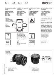
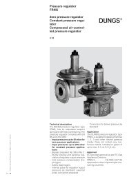
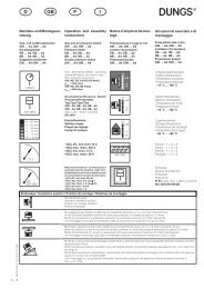
Technical description<br />
The LGW…C2 differential <strong>pressure</strong><br />
<strong>switch</strong> is an adjustable differential <strong>pressure</strong><br />
<strong>switch</strong> <strong>for</strong> automatic burner controls.<br />
It is suitable <strong>for</strong> <strong>switch</strong>ing a circuit on,<br />
off or over on changes in actual <strong>pressure</strong><br />
value relative to the set reference<br />
value. The reference value (<strong>switch</strong>ing<br />
point) is adjusted on a setting wheel<br />
provided with a scale.<br />
Each <strong>pressure</strong> chamber has a stepped<br />
connection of 6 mm dia. to 4 mm dia.<br />
Precise function by special <strong>switch</strong>ing<br />
system mounted in frictionless bearings.<br />
Application<br />
<strong>Differential</strong> <strong>pressure</strong> monitoring in firing,<br />
ventilation <strong>and</strong> <strong>air</strong>-conditioning<br />
systems.<br />
Suitable <strong>for</strong> <strong>air</strong>, <strong>flue</strong> <strong>and</strong> <strong>exhaust</strong> gases.<br />
Approvals<br />
EC type test approval as per EC Gas<br />
Appliance Directive:<br />
LGW C2 CE-0085 AQ 0693<br />
Approvals in other important gas-consuming<br />
countries.
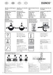
Functional description<br />
<strong>Differential</strong> <strong>pressure</strong> <strong>switch</strong> in <strong>pressure</strong><br />
<strong>and</strong> vacuum ranges.<br />
The differential <strong>pressure</strong> acts via the<br />
diaphragm against the <strong>for</strong>ce of the<br />
setting spring on the micro<strong>switch</strong>.<br />
The <strong>pressure</strong> <strong>switch</strong> operates without<br />
any auxiliary power.<br />
LGW…C2 differential <strong>pressure</strong><br />
<strong>switch</strong><br />
The control unit responds to differential<br />
<strong>pressure</strong>. If the set reference value<br />
(mbar) is exceeded or undershot, the<br />
circuit is <strong>switch</strong>ed on, off or over.<br />
Definition of <strong>switch</strong>ing difference Δp<br />
The <strong>switch</strong>ing difference Δp is the<br />
<strong>pressure</strong> difference between the<br />
upper <strong>and</strong> lower <strong>switch</strong>ing <strong>pressure</strong>s.<br />
Specifications<br />
Max. operating <strong>pressure</strong><br />
Pressure connection<br />
Temperature range<br />
Materials<br />
Switching voltage<br />
Nominal current<br />
Switching current<br />
Electrical connection<br />
Degree of protection<br />
Setting tolerance<br />
LGW…C2 <strong>switch</strong>ing function<br />
As <strong>pressure</strong> rises:<br />
1 NC opens, 2 NO closes<br />
As <strong>pressure</strong> falls:<br />
1 NC closes, 2 NO opens<br />
50 mbar (5 kPa)<br />
Pressure<br />
at meter<br />
Hose connecting piece suitable <strong>for</strong> hose ø 4 / ø 6<br />
Ambient temperature -15 °C to +85 °C<br />
Medium temperature -15 °C to +85 °C<br />
Storage temperature -30 °C to +85 °C<br />
COM<br />
Housing: polycarbonate<br />
Switch: polycarbonate<br />
Diaphragms: NBR<br />
Switching contact: st<strong>and</strong>ard: fine silver (Ag)<br />
optional: gold-plated fine silver (AU); suitable <strong>for</strong><br />
DDC applications: 24 V DC; 0.02 A<br />
Ag contact: AC eff. min. 10 V max. 250 V<br />
DC min. 12 V max. 48 V<br />
Au contact: DC min. 5 V max. 24 V<br />
Ag contact: AC eff. 5 A<br />
Au contact: DC 20 mA<br />
Ag contact: AC eff. max. 5 A at cos ϕ 1<br />
AC eff. max. 3 A at cos ϕ 0.6<br />
AC eff. min. 20 mA<br />
DC min. 20 mA max. 1 A<br />
Au contact: DC min. 5 mA max. 20 mA<br />
At screw terminals via PG* 11 cable gl<strong>and</strong> (* = heavy-gauge conduit thread)<br />
IP 54 as per IEC 529 (DIN 60 529), optional IP 65<br />
Switching difference Δp<br />
3 (P)<br />
Setting tolerance<br />
±15% <strong>switch</strong>ing point deviation referred to reference value<br />
adjusted as vertical diaphragm position, <strong>for</strong> <strong>pressure</strong> direction,<br />
refer to table on page 4.<br />
p<br />
Adjustment as<br />
<strong>pressure</strong> falls<br />
2<br />
1<br />
NO<br />
NC<br />
Upper <strong>switch</strong>ing<br />
<strong>pressure</strong><br />
Rising<br />
Falling<br />
Lower <strong>switch</strong>ing<br />
<strong>pressure</strong><br />
2 … 4
3 … 4<br />
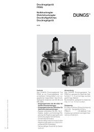
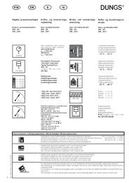
Dimensions [mm]<br />
49,5<br />
44,6<br />
4 x ø 2,5<br />
12 tief / deep /<br />
bas / alto<br />
Pressure connection<br />
Each <strong>pressure</strong> connection<br />
is stepped (6/4 mm dia.).<br />
Schematic diagram<br />
Application <strong>and</strong> connection examples<br />
Connection P1<br />
must remain<br />
open<br />
+<br />
Made in<br />
Germany<br />
49,5<br />
44,6<br />
Connection P2<br />
System vacuum monitor<br />
To monitor the <strong>pressure</strong> in vacuum systems.<br />
LGW…C2 is connected with the <strong>air</strong> duct<br />
via connection p2 (-). Connection p1 (+)<br />
is not connected with the <strong>air</strong> duct.<br />
Do not close hose connection sleeve of<br />
connection p1 (+), there must be a connection<br />
to atmosphere.<br />
Caution: Prevent dirt from entering into<br />
the device through connection p1(+).<br />
Always connect higher <strong>pressure</strong> to<br />
connection p1 (+).<br />
Always connect higher vacuum to connection<br />
p2 (-).<br />
P1<br />
4 x ø 3<br />
12 tief / deep /<br />
bas / alto<br />
71,4<br />
ø 6<br />
ø 4<br />
2 1<br />
–<br />
p2 p1<br />
+<br />
Connection P1 Connection P2<br />
+<br />
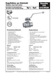
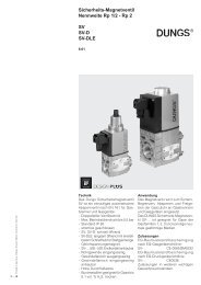
Filter monitoring<br />
To monitor fouling of a filter, the<br />
LGW…C2 can be connected as<br />
shown above.<br />
In the flow direction of the volumetric<br />
flow, the connecting piece p1 (+) is<br />
connected to the <strong>air</strong> channel upstream<br />
of <strong>and</strong> the connecting piece p2 (-)<br />
downstream of the filter.<br />
Example of system <strong>pressure</strong><br />
higher <strong>pressure</strong>:<br />
e.g. 2.8 mbar: connection p1 (+)<br />
lower <strong>pressure</strong>:<br />
e.g. 1.4 mbar: connection p2 (-)<br />
56<br />
18<br />
25<br />
113,5<br />
PG 11<br />
Connection p1 (+) = higher <strong>pressure</strong><br />
Connection p2 (-) = lower <strong>pressure</strong><br />
++<br />
Made in Germany<br />
ø 101<br />
Connection P2 Connection P1<br />
Example of system vacuum<br />
lower vacuum:<br />
e.g. -1.3 mbar: connection p1 (+)<br />
higher vacuum:<br />
e.g. -4.2 mbar: connection p2 (-)<br />
P2<br />
+<br />
Blower monitoring<br />
For blower monitoring, connect connection<br />
p1 (+) to the <strong>air</strong> duct on the<br />
<strong>pressure</strong> side downstream of the<br />
blower <strong>and</strong> connection p2 (-) to the<br />
<strong>air</strong> duct upstream of the blower.
<strong>Differential</strong> <strong>pressure</strong> <strong>switch</strong><br />
<strong>for</strong> <strong>air</strong>, <strong>flue</strong> <strong>and</strong> <strong>exhaust</strong> gases<br />
LGW…C2<br />
Brief technical data<br />
1 mbar = 100 Pa = 0.1 kPa ≈ 10 mm WS 1 Pa = 0.01 mbar ≈ 0.1 mm WS<br />
Type<br />
LGW C2<br />
Design<br />
LGW 1.5 C2<br />
LGW 3 C2<br />
LGW 3 C2<br />
LGW 5 C2<br />
LGW 6 C2<br />
LGW 10 C2<br />
LGW 30 C2<br />
Accessories <strong>for</strong> <strong>pressure</strong> <strong>switch</strong><br />
Order No.<br />
[Ag-PG-V3]<br />
212 200<br />
230 167<br />
212 571<br />
230 168<br />
220 991<br />
212 572<br />
220 992<br />
Klima-Set accessories 217 897<br />
Double adapter kit 221 167<br />
Fixing bracket 230 273<br />
Glowlamp mounting kit 230 V 231 773<br />
Glowlamp mounting kit 120 V 231 772<br />
Pilot lamp mounting kit 24 V 231 774<br />
Replacement-set hood IP 54 230 270<br />
Replacement-set hood IP 65 230 271<br />
Setting range<br />
[mbar]<br />
0.20 - 1.5<br />
0.20 - 3.0<br />
0.40 - 3.0<br />
0.30 - 5.0<br />
0.70 - 6.0<br />
1.0 - 10.0<br />
3.0 - 30.0<br />
We reserve the right to make any changes in the interest of technical progress.<br />
Head Offices <strong>and</strong> Factory<br />
Karl Dungs GmbH & Co.<br />
Siemensstraße 6-10<br />
D-73660 Urbach, Germany<br />
Telephone +49 (0)7181-804-0<br />
Telefax +49 (0)7181-804-166<br />
Switching difference<br />
Δp [mbar]<br />
≤ 0.18<br />
≤ 0.20<br />
≤ 0.20<br />
≤ 0.25<br />
≤ 0.30<br />
≤ 0.40<br />
≤ 0.80<br />
Max. operating<br />
<strong>pressure</strong><br />
[mbar]<br />
50<br />
50<br />
50<br />
50<br />
50<br />
50<br />
50<br />
Postal address<br />
Karl Dungs GmbH & Co.<br />
Postfach 12 29<br />
D-73602 Schorndorf, Germany<br />
e-mail info@dungs.com<br />
Internet www.dungs.com<br />
4 … 4