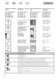
DB FRNG -GB- - fh-teknik a/s
DB FRNG -GB- - fh-teknik a/s
DB FRNG -GB- - fh-teknik a/s

Create successful ePaper yourself
Turn your PDF publications into a flip-book with our unique Google optimized e-Paper software.
Printed in Germany • Rösler Druck • Edition 12.03 • Nr. 219 570<br />
1 … 8<br />
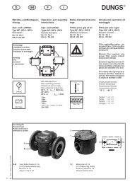
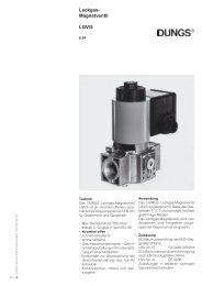
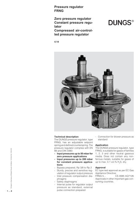
Pressure regulator<br />
<strong>FRNG</strong><br />
Zero pressure regulator<br />
Constant pressure regulator<br />
Compressed air-controlled<br />
pressure regulator<br />
4.14<br />
Technical description<br />
The DUNGS pressure regulator, type<br />
<strong>FRNG</strong>, has an adjustable setpoint<br />
spring and defined counterspring. The<br />
pressure regulator complies with EN<br />
88 and DIN 3380:<br />
- Input pressures up to 50 mbar for<br />
zero pressure applications<br />
- Input pressures up to 200 mbar<br />
for constant pressure applications<br />
- Bypass prepared, Rp 3/8 to Rp 2<br />
- Sturdy, precise and sensitive regulation<br />
of regulator output pressure<br />
- Inlet pressure compensation diaphragms<br />
- Safety diaphragms<br />
- Internal pulse for regulator output<br />
pressure as standard, external<br />
pulse connection prepared<br />
- Connection for blower pressure as<br />
standard<br />
Application<br />
The DUNGS pressure regulator, type<br />
<strong>FRNG</strong>, is suitable for gases of families<br />
1, 2, 3 and other neutral gaseous<br />
media. Does not contain any nonferrous<br />
metals, suitable for gases of<br />
up to max. 0.1 vol.% H 2 S, dry.<br />
Approval<br />
EC type test approval as per EC Gas<br />
Appliance Directive:<br />
<strong>FRNG</strong> 5… CE-0085 AQ7126<br />
Approvals in other important gas consuming<br />
countries.
<strong>FRNG</strong> Spring-loaded pressure regulator with adjustable setpoint spring and defined counterspring. Internal<br />
tap of regulator output pressure, external pulse and blower pressure connections prepared. Suitable for<br />
controlling regulator output pressure via a pneumatic command variable.<br />
Specifications<br />
Nominal diameters<br />
Pipe thread as per ISO 7/1<br />
Flange<br />
Max. operating pressure<br />
Pressure regulator<br />
Input pressure range<br />
Zero pressure regulator<br />
Constant pressure regulator<br />
Compressed air-controlled pressure regulator<br />
Pressure stage<br />
Output pressure range<br />
Materials of gas-conveying parts<br />
Ambient temperature<br />
Installation position<br />
Measuring/ignition gas connections<br />
Measurement opening<br />
Bypass<br />
Pulse connection<br />
Blow-off line / pressure connection<br />
for blower pressure<br />
Blower pressure command variable<br />
DN 10 15 20 25 40 50 65 80 100 125 150<br />
Rp 3/8 1/2 3/4 1 11/2 2<br />
Connection flange per DIN 2501 Part 1, to fit preweld flange as specified in<br />
DIN 2633 (PN 16) DN 40 to DN 100, ISO 7005-2 (PN 16)<br />
up to 500 mbar (50 kPa)<br />
Pressure regulator as per EN 88, Class A, Group 2, DIN 3380 RG 10, EN 12078<br />
5 to 50 mbar<br />
5 to 200 mbar<br />
to 500 mbar<br />
PN 1<br />
Zero pressure regulator - 3 to 5 mbar<br />
Constant pressure regulator -10 to 150 mbar<br />
Pressure with compressed air up to max. 300 mbar.<br />
Housing: aluminium, steel, no non-ferrous metals<br />
Seals and diaphragms: NBR<br />
–15 °C to +70 °C<br />
Regulator dome from vertically upright to lying horizontally<br />
Rp 1/2 - DN 100<br />
DN 125 -HS-, DN 150 -HS- with measuring unit type<br />
Measuring unit guide: Measuring unit with two guides for improved<br />
regulation when the regulator is installed with the regulator dome in<br />
horizontal position. -HS- = Horizontal Support<br />
Regulator dome in vertical position<br />
DN 125, DN 150<br />
G 1/4 ISO 228 on both sides in inlet section<br />
G 1/8 ISO 228 in the baseplate (option DN 125, DN 150)<br />
Reclosable opening for setting system-specific valuas when the system is put<br />
into operation, e. g. gas motor<br />
Bypass prepared: Rp 3/8 to Rp 2 on right of housing<br />
Internal in outlet section,<br />
externally prepared on housing: Rp 3/8 to Rp 1 left, G 1/8;<br />
on both sides from Rp 1 1/2, DN 40 G 1/4; internal pulse lockable<br />
Blow-off line needs no routing, use existing connection as pressure connection<br />
for command variable (blower pressure).<br />
Connection: G 1/4 to Rp 1; from Rp 1 1/2, DN 40: G 1/2<br />
For constant pressure applications and gas-air ratio applications at pressure ratio<br />
of approx. 1:1 and in compressed-air controlled operation: p max = 150 mbar<br />
2 … 8
3 … 8<br />
Spring selection<br />
The output pressure is provided by<br />
the force of the installed adjustable<br />
spring, the counterspring and the the<br />
blower pressure applied. The pres-<br />
Setpoint spring range<br />
[mbar]<br />
Spring colour<br />
Nominal diameter Rp/DN<br />
Rp 3/8, Rp 1/2<br />
Rp 3/4<br />
Rp 1<br />
Rp 1 1/2, DN 40<br />
Rp 2, DN 50<br />
DN 65, 80<br />
DN 100<br />
DN 125<br />
DN 150<br />
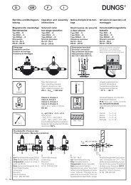
Dimensions<br />
Type<br />
<strong>FRNG</strong> 503<br />
<strong>FRNG</strong> 505<br />
<strong>FRNG</strong> 507<br />
<strong>FRNG</strong> 510<br />
<strong>FRNG</strong> 515<br />
<strong>FRNG</strong> 520<br />
<strong>FRNG</strong> 5040<br />
<strong>FRNG</strong> 5050<br />
<strong>FRNG</strong> 5065<br />
<strong>FRNG</strong> 5080<br />
<strong>FRNG</strong> 5100<br />
<strong>FRNG</strong> 5125<br />
<strong>FRNG</strong> 5150<br />
<strong>FRNG</strong> 5125<br />
<strong>FRNG</strong> 5150<br />
Bypass<br />
restrictor<br />
Rp 3/8 - Rp2<br />
h<br />
Order No.<br />
220 967<br />
220 968<br />
220 969<br />
220 970<br />
209 064<br />
209 065<br />
159 350<br />
209 067<br />
209 068<br />
209 069<br />
214 422<br />
220 758<br />
224 212<br />
243 265 -HS-*<br />
243 266 -HS-*<br />
225 256<br />
d<br />
DN<br />
c<br />
p max.<br />
[mbar]<br />
500<br />
500<br />
500<br />
500<br />
500<br />
500<br />
500<br />
500<br />
500<br />
500<br />
500<br />
500<br />
500<br />
500<br />
500<br />
sure regulator is equipped with the<br />
brown spring No. 1 as standard. By<br />
exchanging the adjustable spring, it is<br />
possible to achieve larger positive zero<br />
b<br />
a<br />
f<br />
g<br />
e<br />
Rp / DN<br />
Rp 3/8<br />
Rp 1/2<br />
Rp 3/4<br />
Rp 1<br />
Rp 1 1/2<br />
Rp 2<br />
DN 40<br />
DN 50<br />
DN 65<br />
DN 80<br />
DN 100<br />
DN 125<br />
DN 150<br />
DN 125<br />
DN 150<br />
Dimensions [mm]<br />
a b c d<br />
75<br />
75<br />
100<br />
110<br />
150<br />
170<br />
200<br />
230<br />
290<br />
310<br />
350<br />
400<br />
480<br />
400<br />
480<br />
115<br />
115<br />
130<br />
145<br />
195<br />
250<br />
195<br />
250<br />
285<br />
285<br />
350<br />
400<br />
480<br />
400<br />
480<br />
24<br />
24<br />
28<br />
33<br />
40<br />
47<br />
65<br />
75<br />
95<br />
95<br />
105<br />
135<br />
160<br />
135<br />
160<br />
h<br />
d<br />
143<br />
143<br />
165<br />
190<br />
250<br />
310<br />
280<br />
340<br />
405<br />
405<br />
495<br />
635<br />
780<br />
635<br />
780<br />
point shifts (offsets) of the output pressure<br />
(refer to Fig. Compressed aircontrolled<br />
pressure regulator).<br />
2.5…+9 5…13 5…20 10…30 25…55 30…70 60…110 100…150 140…200<br />
Spring 1 Spring 2 Spring 3 Spring 4 Spring 5 Spring 6 Spring 7 Spring 8 Spring 9<br />
brown white orange bluw red yellow black pink grey<br />
Standard<br />
Spring 2 to 9 for compressed air applications only<br />
229 817 229 818 229 821 229 821 229 822 229 823 229 824 229 825 229 826<br />
229 833 229 834 229 836 229 836 229 837 229 838 229 839 229 840 229 841<br />
229 842 229 843 229 845 229 845 229 846 229 847 229 848 229 849 229 850<br />
229 851 229 852 229 854 229 854 229 869 229 870 229 871 229 872 229 873<br />
229 874 229 875 229 877 229 877 229 878 229 879 229 880 229 881 229 882<br />
229 883 229 884 229 886 229 886 229 887 229 888 229 889 229 890 229 891<br />
229 892 229 893 229 895 229 895 229 896 229 897 229 898 229 899 229 900<br />
229 901 229 902 229 904 229 904 229 905 229 906 229 907 229 908 243 416<br />
229 909 229 910 229 912 229 912 229 913 229 914 229 915 229 916 243 417<br />
Standard Offset ≤ 5 mbar (Closing force of counterspring in closed position)<br />
e<br />
DN<br />
c<br />
G 1/4<br />
G 1/4<br />
G 1/4<br />
G 1/4<br />
G 1/2<br />
G 1/2<br />
G 1/2<br />
G 1/2<br />
G 1/2<br />
G 1/2<br />
G 1/2<br />
G 1/2<br />
G 1/2<br />
G 1/2<br />
G 1/2<br />
f<br />
b<br />
G 1/4<br />
G 1/4<br />
G 1/4<br />
G 1/4<br />
G 1/4<br />
G 1/4<br />
G 1/4<br />
G 1/4<br />
G 1/4<br />
G 1/4<br />
G 1/4<br />
G 1/4<br />
G 1/4<br />
G 1/4<br />
G 1/4<br />
a<br />
g<br />
V1<br />
+ –<br />
g<br />
G 1/8<br />
G 1/8<br />
G 1/8<br />
G 1/8<br />
G 1/4<br />
G 1/4<br />
G 1/4<br />
G 1/4<br />
G 1/4<br />
G 1/4<br />
G 1/4<br />
G 1/4<br />
G 1/4<br />
G 1/4<br />
G 1/4<br />
h<br />
225<br />
225<br />
245<br />
310<br />
365<br />
450<br />
395<br />
480<br />
590<br />
590<br />
760<br />
1000<br />
1180<br />
1000<br />
1180<br />
Weight<br />
[kg]<br />
0.60<br />
0.60<br />
1.00<br />
1.20<br />
2.50<br />
3.50<br />
3.50<br />
5.00<br />
7.50<br />
10.00<br />
16.00<br />
28.00<br />
38.00<br />
28.00<br />
38.00<br />
* -HS- Horizontal Support/<br />
Measuring unit guide<br />
e
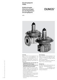
Functional description<br />
Functions according to the force comparison<br />
principle between the force of:<br />
- the adjustable setpoint spring<br />
- the defined counterspring<br />
- the differential pressure at the working<br />
diaphragm<br />
and<br />
- the force due to weight of the moving<br />
parts<br />
The counterspring acts against the<br />
adjustable spring and the weight due<br />
to force of the moving parts. Depending<br />
on the pretension of the adjustable<br />
spring and the installation position,<br />
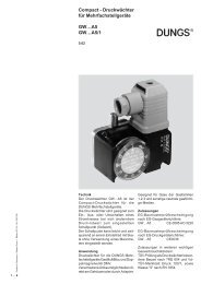
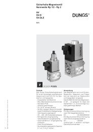
<strong>FRNG</strong> 515 sectional drawing<br />
Pressure regulator in closed position<br />
1 Housing<br />
2 Regulating cup<br />
3 Pulse tap, internal<br />
4 Compensation diaphragm<br />
5 External pulse<br />
5<br />
p 1<br />
the force of the counterspring is compensated.<br />
Overcompensation leads to positive<br />
regulator output pressures, partial<br />
compensation leads to negative regulator<br />
output pressures.<br />
Instructions<br />
Gas-conveying lines, pulse and connection<br />
lines must be made of steel<br />
and at least PN 1, DN 6. The lines must<br />
be resistant to thermal, chemical and<br />
mechanical loads. The lines must be<br />
durable and deformation- and crackproof.<br />
6 Diaphragm disk<br />
7 Working diaphragm<br />
8 Safety diaphragm<br />
9 Breathing plug<br />
10 Setpoint spring<br />
p 2<br />
Do not route condensate<br />
from lines into the pressure<br />
regulator.<br />
Do not apply burning gas or<br />
combustion gas air mixtures<br />
to the installation chamber<br />
of the adjustable spring. Pressure<br />
regulators for this application<br />
on request.<br />
11<br />
10<br />
9<br />
8<br />
7<br />
6<br />
4<br />
3<br />
2<br />
1<br />
12<br />
13<br />
11 Adjustment device<br />
12 Counterspring<br />
13 Option DN 125, DN 150<br />
Measurement opening with<br />
screw plug G 1/8<br />
4 … 8
5 … 8<br />
Application of zero pressure regulator<br />
(standard design)<br />
The <strong>FRNG</strong> regulates a gas flow proportional<br />
to the consumer vacuum<br />
for gas motors and self-intaking gas<br />
equipment.<br />
The regulator is adjusted within the<br />
setting range at the setpoint spring.<br />
V<br />
°<br />
= V<br />
°<br />
x 0.1<br />
min. max.<br />
For V° , see volumetric flow pres-<br />
max<br />
sure drop characteristic.<br />
Application with compressed aircontrolled<br />
pressure regulator<br />
(standard design)<br />
For externally controlled gas equipment.<br />
In connection with a selected setpoint<br />
spring, the regulator output pressure<br />
can be controlled depending on the<br />
blower pressure (compressed air).<br />
The command variable can be up to<br />
+150 mbar.<br />
V<br />
°<br />
= V° x 0.05<br />
min. max.<br />
For V° , see volumetric flow pres-<br />
max<br />
sure drop characteristic.<br />
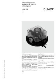
Pressure taps<br />
Pulse and blower connection<br />
1 Breathing plug or connection for<br />
blow-off line. Only route blow-off<br />
line in special cases or connection<br />
for air pulse line<br />
2 Connection for external gas pulse.<br />
Internal pulse must be closed.<br />
3 Pressure connection in inlet section<br />
G 1/4 ISO 228 screw plug, Rp<br />
3/8 to Rp 2 with bypass cover prepared<br />
for mounting adjustable<br />
bypass restriction.<br />
KH GF FRS DMV <strong>FRNG</strong> Gas motor<br />
p 2<br />
[mbar]<br />
Pressure<br />
Vacuum<br />
+5<br />
+1<br />
-1<br />
-3<br />
p 2<br />
[mbar]<br />
Sequential variable<br />
Regulator output pressure p2 Blower<br />
Resulting output pressure<br />
M<br />
Compressed air regulator<br />
Pulse<br />
KH GF DMV <strong>FRNG</strong><br />
Air filter<br />
P L<br />
Command variable –1 0 +1<br />
Blower pressure pL or compressed air<br />
P 2<br />
Mixer<br />
Control air<br />
°<br />
Vmax.<br />
Burner<br />
Setting range p2<br />
-3 mbar … +5 mbar<br />
Pretension of setpoint spring<br />
e.g. spring No. 6 (yellow) 30 - 70 bar<br />
1<br />
p L [mbar]<br />
2<br />
3<br />
° 3<br />
V [m /h]<br />
Option<br />
<strong>FRNG</strong> 503 - 520<br />
V1<br />
+ –
Application of constant pressure<br />
regulator (standard design)<br />
As constant pressure regulator for<br />
gas-air ratio regulators with fixed<br />
efficiency pressure ratio V = 1:1 on<br />
gas equipment operated with differential<br />
pressure.<br />
The offset range of the counterspring<br />
can be set by the setpoint spring.<br />
The moving parts are compensated<br />
by the force due to weight.<br />
Gas supply or air supply are adjustable<br />
at full load and partial load.<br />
Basic load is adjustable via bypass<br />
restrictor.<br />
The command variable can be up to<br />
+150 mbar.<br />
°V = V° x 0,05<br />
min. max.<br />
For V° max, see volumetric flow pressure<br />
drop characteristic.<br />
p 2<br />
[mbar]<br />
Regulator output<br />
1 : 1<br />
Blower<br />
100 % 95 %<br />
Offset range for regulator<br />
characteristic<br />
Blower pressure p L<br />
M<br />
Air Valve<br />
Pulse<br />
KH GF DMV <strong>FRNG</strong><br />
0,95 : 1<br />
Actual pressure ratio<br />
P L<br />
P 2<br />
Adjustable<br />
bypass restrictor<br />
<strong>FRNG</strong> 503 - 520<br />
p L [mbar]<br />
Industrial<br />
burner<br />
6 … 8
7 … 8<br />
Volumetric flow pressure difference characteristic<br />
Bypass restrictor<br />
∆p [mbar]<br />
100<br />
80<br />
60<br />
50<br />
40<br />
30<br />
20<br />
10<br />
8<br />
6<br />
5<br />
4<br />
3<br />
2<br />
1<br />
Recommended operating range<br />
0,1 0,2 0,3 0,4 0,5 0,6 0,8<br />
Bypass restrictor<br />
adjustable for<br />
<strong>FRNG</strong> 503<br />
<strong>FRNG</strong> 505<br />
<strong>FRNG</strong> 507<br />
<strong>FRNG</strong> 510<br />
<strong>FRNG</strong> 515<br />
<strong>FRNG</strong> 520<br />
Order-No.<br />
225 129<br />
+ –<br />
Basis + 15° C, 1013 mbar, trocken<br />
Based on + 15° C, 1013 mbar, dry<br />
Base + 15° C, 1013 mbar, sec<br />
Base + 15° C, 1013 mbar, secco<br />
1 2 3 4 5 6 7 8 910<br />
Vn ° 3<br />
[m /h] Luft / Air / Aria dv = 1,00<br />
0,2 0,3 0,4 0,5 0,6 0,8 1 2 3 4 5 6 7 8910<br />
Vn ° 3<br />
[m /h] Erdgas/Natural gas/Gaz Naturel/Gas metano dv = 0,65<br />
V1
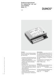
Volumetric flow pressure loss characteristic<br />
∆p [mbar]<br />
100<br />
90<br />
80<br />
70<br />
60<br />
50<br />
40<br />
30<br />
20<br />
10<br />
9<br />
8<br />
7<br />
6<br />
5<br />
4<br />
3<br />
2<br />
1,0<br />
Recommended operating range<br />
Pressure regulator<br />
<strong>FRNG</strong><br />
Zero pressure regulator<br />
Constant pressure regulator<br />
Compressed air-controlled<br />
pressure regulator<br />
1 2 4 6 8 10 20 40 60 80 100 200 400 600 800 1000 2000 4000<br />
° 3<br />
Vn [m /h] Luft / Air / Aria dv = 1,00<br />
1 2 4 6 8 10 20 40 60 80 100 200 400 600 800 1000 2000 4000<br />
° 3<br />
Vn [m /h] Erdgas/Natural gas/Gaz Naturel/Gas metano dv = 0,65<br />
We reserve the right to make any changes in the interest of technical progress.<br />
Rp 3/8<br />
Rp 1/2<br />
Rp 3/4<br />
Rp 1<br />
Head Offices and Factory<br />
Karl Dungs GmbH & Co. KG<br />
Siemensstraße 6-10<br />
D-73660 Urbach, Germany<br />
Telephone +49 (0)7181-804-0<br />
Fax +49 (0)7181-804-166<br />
DN 40 , Rp 1 1/2<br />
DN 50, Rp 2<br />
DN 65<br />
DN 80<br />
DN 100<br />
DN 125<br />
DN 150<br />
Basis + 15° C, 1013 mbar, trocken<br />
Based on + 15° C, 1013 mbar, dry<br />
Base + 15° C, 1013 mbar, sec<br />
Base + 15° C, 1013 mbar, secco<br />
Postal address<br />
Karl Dungs GmbH & Co. KG<br />
Postfach 12 29<br />
D-73602 Schorndorf, Germany<br />
e-mail info@dungs.com<br />
Internet www.dungs.com<br />
8 … 8