Safety engineering guidelines Pneumatic and electric solutions - Festo
Safety engineering guidelines Pneumatic and electric solutions - Festo
Safety engineering guidelines Pneumatic and electric solutions - Festo

Create successful ePaper yourself
Turn your PDF publications into a flip-book with our unique Google optimized e-Paper software.
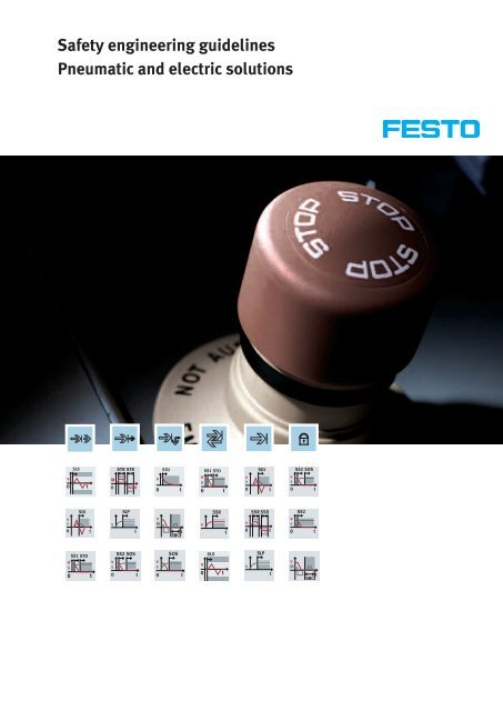
<strong>Safety</strong> <strong>engineering</strong> <strong>guidelines</strong><br />
<strong>Pneumatic</strong> <strong>and</strong> <strong>electric</strong> <strong>solutions</strong><br />
v<br />
0<br />
v<br />
s<br />
0<br />
SLS<br />
SDI<br />
t<br />
SS1 STO<br />
v<br />
s<br />
0<br />
t<br />
t<br />
STR STR<br />
M<br />
0 t<br />
s<br />
v<br />
s<br />
0<br />
SLP<br />
SS2 SOS<br />
t<br />
t<br />
STO<br />
v<br />
0<br />
v<br />
M<br />
v<br />
s<br />
0<br />
t<br />
t<br />
SBC<br />
SOS<br />
t<br />
SS1 STO<br />
v<br />
s<br />
0 t<br />
v s<br />
v<br />
0<br />
SSR SLP<br />
SLS<br />
t t<br />
t<br />
v<br />
s<br />
0<br />
v<br />
0<br />
s<br />
SDI<br />
SSR SSR<br />
SLP<br />
t<br />
t<br />
t<br />
v<br />
s<br />
0<br />
v<br />
s<br />
0<br />
v<br />
M<br />
SS2 SOS<br />
SS2<br />
t<br />
t<br />
t<br />
SBC
Overview of technical safety measures<br />
2<br />
OFF<br />
Input Logic<br />
Input<br />
Emergency stop<br />
Two-h<strong>and</strong><br />
operation:<br />
Moving guard:<br />
safety door<br />
<strong>Safety</strong> shut-off<br />
Light curtain<br />
Laser scanner<br />
Enabling switch<br />
Operating mode<br />
selector switch<br />
Vision system<br />
Please observe the legal information on page 76.<br />
Logic<br />
• Wiring<br />
• Safe, pneumatic solution<br />
• <strong>Safety</strong> relay<br />
• <strong>Safety</strong> PLC<br />
Set-up <strong>and</strong><br />
service operation<br />
Initial position,<br />
st<strong>and</strong>still<br />
Emergency<br />
operation<br />
Normal<br />
operation
<strong>Pneumatic</strong><br />
Reducing speed<br />
Reducing pressure<br />
<strong>and</strong> force<br />
exhausting<br />
Exhausting<br />
Reversing the<br />
movement<br />
Stopping,<br />
holding,<br />
blocking<br />
Stopping,<br />
holding,<br />
blocking<br />
Protection against<br />
unexpected<br />
start-up<br />
Output<br />
Output<br />
v<br />
0<br />
v<br />
0<br />
v<br />
s<br />
0<br />
0<br />
STO<br />
SDI<br />
SS1 STO<br />
v<br />
s<br />
v<br />
s<br />
0<br />
v<br />
s<br />
0<br />
s<br />
SLS<br />
SS2 SOS<br />
You will see these symbols frequently on the following pages.<br />
They clearly <strong>and</strong> quickly point to the respective safety function.<br />
SOS<br />
SLP<br />
Electrical<br />
t<br />
t<br />
t<br />
t<br />
t<br />
t<br />
t<br />
Safely limited<br />
speed (SLS)<br />
Safe torque off<br />
(STO)<br />
Safe direction<br />
of movement<br />
(SDI)<br />
Safe stop 1<br />
(SS1)<br />
Safe stop 2<br />
(SS2)<br />
Safe operating<br />
stop<br />
(SOS)<br />
Safe position SPF<br />
(SLP)<br />
3
Your partner for safety<br />
Quality has many aspects at <strong>Festo</strong>, one of which is working safely with<br />
machines. This has led to our safety-oriented automation technology. These<br />
components ensure that optimum safety is achieved in the workplace.<br />
4<br />
Contents<br />
This brochure is intended as a<br />
guide. It covers the core<br />
questions relating to safetyoriented<br />
pneumatics <strong>and</strong><br />
<strong>electric</strong>al <strong>engineering</strong>:<br />
• Why use safety-orientated<br />
pneumatics?<br />
• How can I identify the risk<br />
posed by a system or machine<br />
to the operator or user?<br />
• Which st<strong>and</strong>ards <strong>and</strong> directives<br />
apply?<br />
• What safety measures are<br />
derived from these?<br />
• What are the most common<br />
safety measures?<br />
Simple <strong>and</strong> helpful:<br />
The directives <strong>and</strong> st<strong>and</strong>ards are<br />
dealt with in the first part of the<br />
brochure. The second part offers<br />
an overview of the most<br />
commonly used safety<br />
functions in connection<br />
with pneumatic <strong>and</strong> <strong>electric</strong><br />
Introduction ....................................................................................... 5<br />
Directives <strong>and</strong> st<strong>and</strong>ards .................................................................... 5<br />
<strong>Safety</strong> functions through products <strong>and</strong> <strong>solutions</strong> ............................. 27<br />
• <strong>Pneumatic</strong>s ..........................................................................27<br />
• Servopneumatics ................................................................. 55<br />
• Electrical components ......................................................... 60<br />
• Application <strong>and</strong> programming examples ............................. 66<br />
Training <strong>and</strong> consulting .................................................................... 70<br />
drives, as well as the<br />
corresponding <strong>solutions</strong> from<br />
<strong>Festo</strong>. These can be used to<br />
implement many safety<br />
functions.<br />
If you require more information,<br />
our specialists worldwide will be<br />
happy to help.
Reduce risk – think preventively<br />
Machines have to be designed in a way that protects people, animals, property<br />
<strong>and</strong> the environment from harm. The objective is to prevent physical damage of<br />
any type. Using safety-oriented pneumatic <strong>and</strong> <strong>electric</strong>al components from <strong>Festo</strong><br />
provides you with the security of implementing safety measures that are<br />
compliant with the EC Machinery Directive.<br />
This reliably prevents collisions<br />
or uncontrolled restarts after an<br />
emergency stop, for example. At<br />
the same time, using safetyoriented<br />
pneumatics also<br />
minimises the risk of liability<br />
claims.<br />
The EC Machinery Directive<br />
2006/42/EC specifies a risk<br />
analysis <strong>and</strong> assessment for<br />
machines. These have helped to<br />
develop <strong>and</strong> define safety<br />
objectives.<br />
Simple but safe<br />
As a general rule, the simpler the<br />
safety technology used in the<br />
application, the more efficient it<br />
is. The complexity of safety<br />
<strong>engineering</strong> is in the variety of<br />
state combinations <strong>and</strong><br />
transitional states.<br />
The safety objectives are<br />
achieved using various safety<br />
functions.<br />
<strong>Safety</strong>-oriented <strong>solutions</strong> in the<br />
form of<br />
• Components<br />
• Circuits<br />
• Engineering<br />
make it easy to achieve your<br />
safety objectives. Reliable<br />
operation of machines should be<br />
possible in all modes <strong>and</strong> stages<br />
of their service life.<br />
As a result, it would seem<br />
virtually impossible to implement<br />
st<strong>and</strong>ardised safety <strong>engineering</strong><br />
concepts.<br />
Due to their flexible application,<br />
drive systems need to be<br />
included in the risk analysis <strong>and</strong><br />
assessment for each machine,<br />
depending on the application.<br />
<strong>Safety</strong>-oriented <strong>solutions</strong> from<br />
<strong>Festo</strong> provide you with proposals<br />
for<br />
• Commissioning<br />
• Automatic/manual operation<br />
• Setting up<br />
• Risk situations <strong>and</strong> emergency<br />
functions, such as safe<br />
stopping, safe exhausting.<br />
• Restarting -> protection against<br />
unexpected start-up<br />
• Servicing/maintenance<br />
In addition to this, if faults occur,<br />
they must not lead to failure of<br />
the safety functions, depending<br />
on their hazard potential.<br />
5
Technical safety conditions<br />
There are legal requirements globally to ensure that machinery can be built <strong>and</strong><br />
operated safely. Almost all laws require a risk assessment which reveals risks<br />
<strong>and</strong> results in risk minimising measures.<br />
6<br />
<strong>Festo</strong> Didactic: Training <strong>and</strong> Consulting<br />
<strong>Festo</strong> <strong>solutions</strong><br />
Laws, e.g. EU Machinery Directive<br />
2006/42/EC<br />
Risk assessment<br />
Risk analysis Risk assessment Risk reduction<br />
Design measures<br />
Technical measures<br />
User information<br />
Input<br />
<strong>Safety</strong> function<br />
EN ISO 13849-1 IEC 61508/61511/62061<br />
Evaluation:<br />
PL ≥ PLr SIL ≥ SILr<br />
Logic Output<br />
Objective: safe machines<br />
Objective: st<strong>and</strong>ardised process<br />
+ "check list"<br />
Objective: risk reduction<br />
Objective: evaluation <strong>and</strong><br />
assessment of technical safety<br />
measures<br />
Objective: evaluation whether<br />
risk reduction is sufficient
Basic safety requirements in the manufacturing industry<br />
At the same time as the development of the single European market, the<br />
directives for machine construction in the manufacturing industry were<br />
harmonised.<br />
Article 95 of the EU Treaty<br />
(free movement of goods)<br />
Low Voltage Directive<br />
2006/95/EC<br />
e.g. machines<br />
Harmonised European st<strong>and</strong>ards National legal provisions<br />
Responsibility<br />
Directives are comparable with<br />
laws. Among others, the EC<br />
Machinery Directive is applicable<br />
for machine construction. The<br />
primary aim of the EC Machinery<br />
Directive is to specify basic<br />
health <strong>and</strong> safety requirements<br />
in relation to the design <strong>and</strong><br />
construction of machines. The CE<br />
mark indicates compliance with<br />
Free movement of goods within Europe<br />
EC Machinery<br />
Directive<br />
2006/42/EC<br />
Manufacturers Operators<br />
the Machinery Directive.<br />
Harmonised st<strong>and</strong>ards provide<br />
support for compliance with the<br />
EC Machinery Directive. These<br />
are listed in the Official Journal of<br />
the European Communities.<br />
Applying these results is what is<br />
known as the "presumption of<br />
conformity", which reinforces the<br />
legal security of operators <strong>and</strong><br />
Article 137 of the EU Treaty<br />
(safety <strong>and</strong> health at work)<br />
"<strong>Safety</strong> <strong>and</strong> Health" Framework Directive<br />
89/391/EEC<br />
"Use of work equipment"<br />
single directive<br />
86/655/EEC<br />
manufacturers.<br />
7
Basic st<strong>and</strong>ards for designing control functions<br />
Harmonised st<strong>and</strong>ards that relate to machine safety help to reduce<br />
safety risks to an acceptable minimum, as per the EC Machinery<br />
Directive.<br />
8<br />
Design <strong>and</strong> risk assessment of machinery<br />
EN ISO 12100<br />
<strong>Safety</strong> of machinery<br />
General principles for design<br />
Functional <strong>and</strong> safety-oriented requirements for<br />
safety-related control systems<br />
Designing <strong>and</strong> implementing safety-related control systems<br />
Electrical safety aspects<br />
EN 60204-1<br />
<strong>Safety</strong> of machinery<br />
Electrical equipment of machines,<br />
Part 1: General requirements<br />
EN 62061<br />
<strong>Safety</strong> of machinery<br />
Functional safety of <strong>electric</strong>al/electronic/programmable safety-related electronic control systems<br />
Any architectures<br />
<strong>Safety</strong> integrity level (SIL)<br />
SIL 1, SIL 2, SIL 3<br />
DIN EN ISO 13849-1<br />
<strong>Safety</strong> of machinery<br />
<strong>Safety</strong>-related parts of control systems, Part 1 – General principles for design<br />
Designated architectures (categories)<br />
Performance level (PL)<br />
PL a, PL b, PL c, PL d, PL e
Definition of risk<br />
Risks are the result of hazards<br />
<strong>and</strong> relate to the gravity of<br />
possible damage <strong>and</strong> the<br />
probability of the damage<br />
occurring.<br />
Low risk<br />
safety Risk limit<br />
Danger<br />
Risk<br />
in terms of the respective<br />
hazard<br />
Residual risk<br />
<strong>Safety</strong> = accepted residual risk<br />
= +<br />
Severity<br />
of the possible damage<br />
Required minimum risk minimisation<br />
Probability that damage<br />
will occur<br />
Actual risk reduction<br />
Risk without<br />
safety measures<br />
Frequency <strong>and</strong> duration of<br />
exposure to the hazard<br />
Options for avoiding or<br />
limiting the damage<br />
High risk<br />
Probability of an event that<br />
could cause the damage<br />
occurring<br />
9
Risk assessment<br />
Directives <strong>and</strong> st<strong>and</strong>ards describe the risk assessment process.<br />
All manufacturers are obligated to perform a risk assessment.<br />
This is followed by a risk evaluation <strong>and</strong> appropriate risk reduction<br />
measures must be implemented as required.<br />
Focusing on risk reduction<br />
This guide is primarily concerned<br />
with the area of risk reduction in<br />
the form of technical safety<br />
measures. We assume that all<br />
possible design measures for<br />
reducing risk have already been<br />
explored.<br />
10<br />
Risk assessment<br />
Source: EN ISO 12100<br />
Risk analysis<br />
Source: EN ISO 12100<br />
Risk assessment<br />
Source: EN ISO 12100<br />
Start<br />
Determine the limits of the<br />
machine<br />
Source:<br />
EN ISO 12100<br />
Determine hazardous<br />
situation<br />
Source:Source:<br />
EN ISO 12100<br />
Risk evaluation<br />
Source:<br />
EN ISO 12100<br />
Risk assessment<br />
of design safety<br />
measures – Is the<br />
machine safe?<br />
Instructive measures<br />
exhausted<br />
End<br />
Yes<br />
Risk assessment<br />
of technical safety<br />
measures – Is the<br />
machine<br />
safe?<br />
Yes<br />
Yes<br />
No<br />
No<br />
No<br />
Source: Directive 2006/42/EC Appendix I,<br />
1)<br />
Identifying/examining the<br />
system limits<br />
• Limits of use<br />
• Space limits<br />
• Time limits<br />
Determine/define<br />
states & transitional states<br />
• Human intervention<br />
• Operating statuses<br />
• Unintentional behaviour<br />
or foreseeable misuse<br />
• Preliminary hazard<br />
analysis (PHA)<br />
• "WHAT IF" method<br />
• Failure mode <strong>and</strong> effects<br />
analysis, failure effects<br />
analysis (FMEA)<br />
• Failure simulation for<br />
control systems<br />
• MOSAR procedure<br />
• Fault tree analysis;<br />
(FTA)<br />
Source: EN ISO 12100
For all safety functions<br />
Design measures<br />
e.g. inherent safety<br />
Source: EN ISO 12100<br />
Technical safety measures <strong>and</strong> supplementary<br />
safety measures<br />
Selecting the safety function<br />
Defining the characteristics of the safety function<br />
Determining PL r<br />
Design <strong>and</strong> technical implementation of the<br />
safety function<br />
Determining PL<br />
Category MTTF d<br />
PL ≥ PL r<br />
Yes<br />
No<br />
Source: DIN EN ISO 13849-1, 4.2 Fig. 3<br />
User information on the machine <strong>and</strong> in the user<br />
manual<br />
Source: EN SO 12100<br />
dC CCF<br />
Risk reduction<br />
Source: EN ISO 12100<br />
When assessing risk <strong>and</strong><br />
identifying the necessary<br />
performance level, the degree of<br />
risk reduction is established.<br />
Whether or not the required risk<br />
reduction level has been<br />
achieved depends on the<br />
following parameters:<br />
1) Control architecture<br />
2) Mean time to dangerous<br />
failure (MTTFd)<br />
3) Diagnostic coverage (DC)<br />
4) Common cause failures (CCF)<br />
In all cases, the Performance<br />
Level PL must correspond at least<br />
to the required PL r .<br />
11
Evaluating technical safety measures – Determining the performance level<br />
The figure shows the simplified<br />
procedure for determining the<br />
performance level (PL) of a safety<br />
function. The PL is a function of<br />
categories B to 4, diagnostic<br />
coverage "none to high", various<br />
MTTF d areas <strong>and</strong> the Common<br />
Cause Failure.<br />
The PL can be assigned to a<br />
specific SIL level. However, it is<br />
not possible to infer the PL from<br />
the SIL. Apart from the average<br />
probability of one dangerous<br />
failure per hour, DIN EN ISO<br />
13849-1 requires other measures<br />
to be taken (e.g. architecture) to<br />
achieve a specific PL.<br />
12<br />
Determining PL = performance level<br />
1<br />
2<br />
3<br />
4<br />
5<br />
1<br />
a<br />
b<br />
c<br />
d<br />
e<br />
4<br />
2<br />
5<br />
DC < 60%<br />
None<br />
Cat. B<br />
Risk graph: Which Performance Level is<br />
required? PL r a to e<br />
How is the control chain or safety function<br />
structured? Category B to 4<br />
Reliability of components in the control<br />
chain: Determining the MTTFd for the entire<br />
process chain, from the sensor to the<br />
actuator!<br />
Degree of diagnostic coverage: which<br />
dangerous faults are detected?<br />
Common cause failures (CCF): measures for<br />
avoiding CCF<br />
Determining the MTTF d = Mean time to failure (dangerous)<br />
DC < 60%<br />
None<br />
Cat. 1<br />
60% ≤ DC<br />
< 90%<br />
Low<br />
Cat. 2<br />
90% ≤ DC<br />
< 99%<br />
Medium<br />
60% ≤ DC<br />
< 90%<br />
Low<br />
Cat. 3<br />
CCF not relevant CCF 65 %<br />
3<br />
Evaluation<br />
90% ≤ DC<br />
< 99%<br />
Medium<br />
DIN EN ISO 13849-1<br />
Chapter 4.5.4<br />
99% ≤ DC<br />
High<br />
Cat. 4<br />
Low 3 years ≤ MTTF d < 10 years<br />
Medium<br />
High<br />
≤<br />
MTTF d<br />
Source: DIN EN ISO 13849-1 Chapter 4.5.2<br />
1<br />
2<br />
3<br />
10 –5 ≤ PFH d < 10 –4<br />
3 x 10 –6 ≤ PFH d < 10 –5<br />
10 –6 ≤ PFH d < 3 x 10 –6<br />
10 –7 ≤ PFH d < 10 –6<br />
10 –8 ≤ PFH d < 10 –7<br />
10 years ≤ MTTF d < 30 years<br />
30 years ≤ MTTF d < 100 years<br />
Determining SIL = safety integrity level
Determining the required performance level<br />
The graph for determining the<br />
required performance level is<br />
based on identifying the risk <strong>and</strong><br />
the resulting necessity for<br />
reducing this to an acceptable<br />
level.<br />
Low risk results in PL = a<br />
(minimal measures for risk<br />
reduction).<br />
High risk results in PL = e<br />
(comprehensive measures for<br />
risk reduction).<br />
Technically speaking, PL r<br />
(required) is a "nominal value",<br />
which is the minimum that<br />
should be achieved by the<br />
technical measures.<br />
Statements from EN 62061 are<br />
also quoted here for a better<br />
assessment of risks. The risk is<br />
always evaluated in the same<br />
way, that is as the severity of<br />
possible damage <strong>and</strong> the<br />
probability that damage will<br />
occur.<br />
DIN EN ISO 13849-1<br />
S1<br />
S2<br />
S Severity of injury<br />
F1<br />
F2<br />
F1<br />
F2<br />
S1 Slight (normally reversible injury)<br />
S2 Serious (normally irreversible injury, including<br />
death)<br />
F Frequency <strong>and</strong>/or duration of exposure to the<br />
hazard<br />
F1 Seldom to less often <strong>and</strong>/or brief<br />
F2 Frequent to continuous <strong>and</strong>/or long<br />
P Possibility of avoiding the hazard<br />
P1 Possible under specific conditions<br />
P2 Scarcely ever possible<br />
P1<br />
P2<br />
P1<br />
P2<br />
P1<br />
P2<br />
P1<br />
P2<br />
Low risk<br />
High risk<br />
Statements from other st<strong>and</strong>ards<br />
EN 62061<br />
a<br />
b<br />
c<br />
d<br />
e<br />
Source:<br />
DIN EN ISO 13849-1 Appendix 1.2.3<br />
Irreversible injury (4 points)<br />
(death, loss of eye or arm)<br />
Irreversible injury (3 points)<br />
(broken limbs, loss of finger)<br />
Reversible injury (2 points)<br />
(requires further medical attention from a doctor)<br />
Reversible injury (1 point)<br />
Frequency (with a duration > 10 min)<br />
< 1 h (5 points)<br />
> 1 h to < 1 day (5 points*)<br />
> 1 day to < 2 weeks (4 points*)<br />
> 2 weeks to < 1 year (3 points*)<br />
> 1 year (2 points*)<br />
* If exposure lasts less than 10 min, this can be reduced one level<br />
Impossible (5 points)<br />
Seldom (3 points)<br />
Probable (1 point)<br />
13
Overview of control architectures<br />
Category B or 1<br />
Category 2 Category 3 Category 4<br />
14<br />
1 channel<br />
0 Fault safety<br />
(DIN EN ISO<br />
13849-1 Pt. 6.2.3)<br />
Category B<br />
I<br />
I<br />
im im<br />
L O<br />
im im<br />
L O<br />
TE<br />
M<br />
1 channel<br />
im<br />
Fundamental safety principles must be fulfilled<br />
(DIN EN ISO 13849-1 Pt. 6.2.3/DIN EN ISO 13849-2 Tab. A 1/B.1/D.1)<br />
Suitable design for external influences<br />
(DIN EN ISO 13849-1 Pt. 6.2.3)<br />
SRP/CS: proven safety principles must be fulfilled<br />
(DIN EN ISO 13849-2 B.4; refer to DIN EN ISO 13849-2 Tab. A.2/B.2/D.2)<br />
Reliable components of the SRP/CS,<br />
(DIN EN ISO 13849-2 A.4/B.4/D.4)<br />
0 Fault safety<br />
(DIN EN ISO 13849-1 Pt. 6.2.4)<br />
Compliance with<br />
fundamental <strong>and</strong><br />
proven safety<br />
principles. Compliance<br />
with ap propriate<br />
st<strong>and</strong>ards<br />
Category 1<br />
OTE<br />
Components proven<br />
in operation. Already<br />
used in similar<br />
applications (refer to<br />
DIN EN ISO 13849-2<br />
B.4)<br />
I1<br />
I2<br />
im<br />
im<br />
L1<br />
M<br />
im O1<br />
c<br />
L2<br />
1 channel<br />
100x test of the<br />
function before the<br />
request by the<br />
machine control<br />
system<br />
(DIN EN ISO 13849-1<br />
Pt. 6.2.5)<br />
0 Fault safety<br />
between the test<br />
phases<br />
Category 2<br />
M<br />
im<br />
O2<br />
2 channels<br />
(DIN EN ISO 13849-1<br />
Pt. 6.2.7)<br />
Some, but not all<br />
faults are detected<br />
before or during the<br />
next request<br />
1 Fault safety<br />
Multiple undetected<br />
faults lead to the loss<br />
of SF<br />
Category 3<br />
I1<br />
I2<br />
im<br />
im<br />
2 channels<br />
(refer to DIN EN ISO<br />
13849-1 Pt. 6.2.7)<br />
Every fault must be<br />
detected before or<br />
during the next<br />
request<br />
> 1 fault safety<br />
Category 4<br />
L1<br />
M<br />
im O1<br />
c<br />
L2<br />
M<br />
im O2
Category 2 application: Pick & Place<br />
<strong>Pneumatic</strong> implementation of a<br />
category 2 solution<br />
In this example, the parts<br />
relevant for the safety function<br />
are also used for normal control<br />
of the system. This is used for<br />
testing. If this is not possible, it<br />
is easier to implement Category 3<br />
for many <strong>solutions</strong> in pneumatic<br />
safety controls, even if a<br />
Category 2 would actually be<br />
sufficient.<br />
The circuit must be tested at<br />
least 100 times before the<br />
safety function is requested.<br />
This test of the pneumatic<br />
components must be<br />
performed without causing<br />
hazards.<br />
<strong>Safety</strong><br />
switch<br />
Feedback of the control system via the PLC Feedback of the safety door<br />
switch to S-PLC<br />
PLC<br />
S-PLC<br />
Diagnostics<br />
Sporadic manipulation after<br />
more than 100 cycles.<br />
Manipulation via the safety door.<br />
<strong>Safety</strong><br />
switch<br />
15
Defining the diagnostic coverage (DC)<br />
This table shows a summary of<br />
sources of error related to<br />
pneumatics, taken from DIN EN<br />
ISO 13849-2. Under certain<br />
conditions, it is possible to<br />
exclude faults. The requirements<br />
for excluding a fault are<br />
described in detail in DIN EN ISO<br />
13849-2. Depending on the<br />
construction principle <strong>and</strong> the<br />
design of components, different<br />
results may arise for different<br />
applications.<br />
In other words, a specific product<br />
may be suitable for one<br />
application but not for another.<br />
The design engineer for the<br />
installation is responsible for<br />
checking this.<br />
16<br />
Products<br />
Directional control valves<br />
Shut-off/non-return/quick<br />
exhaust/shuttle valves<br />
Flow control valves<br />
Pressure regulators<br />
Piping<br />
Tubing<br />
Connecting components<br />
Pressure intensifier <strong>and</strong><br />
pressure medium converter<br />
Filters<br />
Lubricators<br />
Silencers<br />
Energy storage device <strong>and</strong><br />
reservoir<br />
Sensors<br />
Logic elements (AND/OR)<br />
Delay elements<br />
Transformers (pressure switch,<br />
position switch <strong>and</strong> amplifier)<br />
Cylinders<br />
Sources of error<br />
Change to the response times<br />
Non-switching/not switching<br />
back<br />
Auto-switching<br />
Leakage<br />
Change to the leakage over a<br />
long period of use<br />
Cracking of the housing/<br />
connecting piece/tubing<br />
Change to the flow rate without<br />
assistance (adjustable)<br />
Change to the flow rate without<br />
assistance (fixed)<br />
Change to the behaviour<br />
without assistance<br />
For proportional flow valves:<br />
unintentional change to the<br />
setting value<br />
Automatic change to the<br />
adjusting device
Unintentional loosening of the<br />
operating elements in the<br />
adjusting device<br />
Fault in the connecting<br />
component (ripped off/out,<br />
leakage)<br />
Clogging (blockage)<br />
Bending<br />
Change to the recording <strong>and</strong><br />
output characteristics<br />
Failure of the end-position<br />
cushioning<br />
Loosening of the piston/piston<br />
rod connection<br />
Pressure rise<br />
Pressure failure<br />
Electrical power failure<br />
(Recognised<br />
dangerous failures)<br />
DC =<br />
1<br />
(Total dangerous<br />
failures)<br />
Key<br />
DC avg =<br />
Not relevant for this<br />
component<br />
Freedom from faults<br />
partially guaranteed in<br />
the component (see DIN<br />
EN ISO 13849-2)<br />
No freedom from faults<br />
guaranteed for this<br />
component<br />
DC1 DC2 DCN + + ... +<br />
MTTFd1 MTTFd2 MTTF dN<br />
1 1 1<br />
+ + ... +<br />
MTTFd1 MTTFd2 MTTF dN<br />
17
Determining the Mean Time To Dangerous Failure (MTTFd)<br />
The mean time to dangerous<br />
failure (MTTF d ) is initially<br />
determined for each redundant<br />
channel. An overall MTTF d value<br />
is then determined using the<br />
values from both channels. This<br />
value has a unit (e.g. years) <strong>and</strong><br />
is a qualitative statement of the<br />
safety function. In line with the<br />
applicable st<strong>and</strong>ard, the<br />
technical safety measure is<br />
assessed <strong>and</strong> given one of three<br />
classifications: low, medium <strong>and</strong><br />
high.<br />
18<br />
Input input signal<br />
Logic Control signal Output<br />
MTTF d<br />
Service life characteristics of the relevant products<br />
MTTF d<br />
______ 1<br />
= N<br />
_______ 1<br />
i=1<br />
MTTF d<br />
MTTF d,i<br />
B10<br />
Application<br />
data<br />
MTTF d<br />
Evaluation MTTFd Low 3 years ≤ MTTFd < 10 years<br />
Medium 10 years ≤ MTTFd < 30 years<br />
High 30 years ≤ MTTFd < 100 years<br />
Source: DIN EN ISO 13849-1 Chapter 4.5.2
B 10 value<br />
Definition<br />
Time at which statistically 10% of<br />
test specimens have failed (the<br />
values are determined according<br />
to DIN EN ISO 19973).<br />
Per definition, 10% of the test<br />
specimens have failed at this<br />
time. A component can thus also<br />
fail before the B 10 value is<br />
reached. The service life cannot<br />
be guaranteed.<br />
Dangerous failures:<br />
In relation to the safety of<br />
machines/the EC Machinery<br />
Directive/DIN ISO 13849-1, only<br />
dangerous failures are relevant.<br />
It depends on the respective<br />
application whether the failure is<br />
a dangerous failure. If no<br />
information is possible/available<br />
on the number of dangerous<br />
failures, ISO 13849 permits the<br />
assumption that every second<br />
failure is dangerous. It can be<br />
assumed that B 10 d = 2*B10 :<br />
B 10 : Statistical probability of<br />
failure<br />
B 10 d : Statistical probability of<br />
failure due to dangerous<br />
faults<br />
For which products do I require a<br />
B 10 d value?<br />
For all products which are subject<br />
to wear, are used in safetyrelated<br />
parts of a control system<br />
<strong>and</strong> directly contribute to the<br />
execution of a safety function,<br />
such as valves, clamping<br />
cartridges, for example.<br />
This does not apply to fittings,<br />
tubes, angle brackets, fixtures,<br />
etc.<br />
For which products do I require a<br />
MTTF d value?<br />
For all products which are used in<br />
safety-related parts of a control<br />
system <strong>and</strong> directly contribute to<br />
the execution of a safety<br />
Determining MTTF d from B 10 d<br />
The MTTF d value is application-dependent <strong>and</strong> describes the mean period to a dangerous failure of a system part.<br />
Formula for determining the<br />
MTTF d value for a mechanical<br />
element in a channel<br />
Mean number of annual<br />
actuations n op for the mechanical<br />
element<br />
Calculation of overall MTTF d for<br />
two different channels<br />
MTTF d =<br />
n op =<br />
B 10 d<br />
0.1 • n op<br />
dop • hop • 3600s/h<br />
tcycle MTTFd = MTTF 2<br />
dC1 + MTTFdC2 –<br />
3<br />
Where:<br />
B10 d [cycles] = Mean number of<br />
cycles, up to 10% of the<br />
components fail dangerously B 10 d<br />
= 2xB 10<br />
hop [h/d]: Operating hours/day<br />
dop [d/anno]: Operating days/year<br />
tcycle [s]: Cycle time<br />
1<br />
MTTF dC1<br />
1<br />
+<br />
1<br />
MTTF dC2<br />
function, such as controllers,<br />
fieldbus nodes which serve to<br />
detect dangerous situations,<br />
sensors (test channel<br />
Category 2).<br />
Do I need an MTTF d value or B 10<br />
value for components which are<br />
used for monitoring purposes in<br />
safety-related parts of control<br />
systems?<br />
No, for SRP/CS Category 3 <strong>and</strong> 4.<br />
Yes, for SRP/CS Category 2 in the<br />
test channel.<br />
MTTF dC1 <strong>and</strong> MTTF dC2:<br />
Values for two different, redundant<br />
channels.<br />
If the MTTFd value of a channel is<br />
more than 100 years, a value of<br />
100 years is used for further<br />
calculation.<br />
19
<strong>Safety</strong> <strong>engineering</strong> coefficients – Sistema libraries<br />
20<br />
Sistema software from the<br />
Institute for Occupational <strong>Safety</strong><br />
<strong>and</strong> Health [Institut für<br />
Arbeitsschutz (IFA)]<br />
The SISTEMA software assistant<br />
(safety of control systems in<br />
machinery) provides support in<br />
evaluating the safety of SRP/CS<br />
as part of DIN EN ISO 13849-1.<br />
The Windows tool maps the<br />
structure of the safety-related<br />
control parts (SRP/CS, <strong>Safety</strong>-<br />
Related Parts of a Control<br />
Sistema database from <strong>Festo</strong><br />
The Sistema software is only the<br />
tool for performing the safety<br />
<strong>engineering</strong> evaluations.<br />
Databases with safety-related<br />
specifications for products <strong>and</strong><br />
<strong>solutions</strong> provide support with<br />
the evaluation.<br />
There are numerous libraries on<br />
the homepage of the IFA.<br />
System) on the basis of the<br />
designated architectures <strong>and</strong><br />
calculates reliability values at<br />
various levels of detail, including<br />
the Performance Level (PL)<br />
reached.<br />
The software is available as a<br />
free download from the following<br />
link:<br />
www.dguv.de/ifa/de/pra/<br />
softwa/sistema/index.jsp<br />
The libraries of <strong>Festo</strong>'s safety<br />
<strong>engineering</strong> coefficients are<br />
available to download on <strong>Festo</strong>'s<br />
homepage: www.festo.com/<br />
sicherheitstechnik<br />
www.festo.com/safety
<strong>Pneumatic</strong> diagnostic options<br />
Plausibility check<br />
A PLC checks whether a signal change has taken place within a<br />
specific period t, <strong>and</strong> whether the desired change in status has<br />
occurred.<br />
A plausibility check reveals<br />
faults with different causes<br />
• Solenoid coils, final control<br />
element or pushbutton<br />
generate a signal<br />
• Energy switching element,<br />
a valve in this case<br />
Change of status<br />
• From 0 to 1 or<br />
• from 1 to 0<br />
Sensors<br />
For example piston position<br />
sensing, pressure sensor,<br />
proximity sensor, displacement<br />
encoder, flow meter or the<br />
sensors must register the change<br />
of the switching status.<br />
Plausibility<br />
check t<br />
Status<br />
1<br />
PLC<br />
Output<br />
signal<br />
t t<br />
Proximity sensor (S1, S2)<br />
Displacement encoders<br />
0<br />
0 5 10 15 20 25<br />
Flow meter<br />
Pressure<br />
sensors<br />
Switching position sensing<br />
Signal (solenoid coil, final<br />
control element,<br />
pushbutton)<br />
Sensor<br />
(piston position sensing,<br />
pressure sensor, proximity<br />
sensor, flow meter, roller<br />
lever)<br />
21
How test pulses affect solenoid valves<br />
Fail-safe output modules of<br />
safety control systems <strong>and</strong><br />
electronic safety switchgear<br />
connect test pulses to their<br />
outputs for diagnostic purposes.<br />
On the one h<strong>and</strong>, test pulses<br />
help detect cross circuits or to<br />
check the function of the outputs<br />
relative to their deactivation<br />
efficiency. Depending on the<br />
manufacturer, these test pulses<br />
have varying pulse widths of up<br />
to several milliseconds. For<br />
example, a controller<br />
manufacturer deactivates their<br />
outputs for a period of several<br />
milliseconds in the event of an<br />
ON signal. In the event of an OFF<br />
signal, the outputs are switched<br />
on for up to 4 ms to check<br />
whether they can be deactivated<br />
safely if a safety function request<br />
is made.<br />
22<br />
How does a solenoid valve react<br />
to these test pulses?<br />
If a solenoid valve is connected<br />
to a failsafe output, the test<br />
pulses often cause the LED on<br />
the solenoid valve to flicker at<br />
the same speed as the pulses<br />
<strong>and</strong> a clicking can be heard in the<br />
solenoid valve. That clearly<br />
shows that these test pulses<br />
have an effect on the solenoid<br />
valve. Many modern solenoid<br />
valves consist of a magnetic<br />
system, which actuates a pilot<br />
valve via an armature, which in<br />
turn actuates the main part,<br />
which then controls the<br />
actuators. Even if the switching<br />
times for activation or<br />
deactivation, which are listed in<br />
the technical data, are far higher<br />
than the duration of the test<br />
pulses, the armature reacts much<br />
earlier. In some solenoid valves,<br />
this occurs with blackout times<br />
of just 0.1 ms.<br />
Does this result in accidental<br />
deactivation of a solenoid valve<br />
in the event of an ON signal?<br />
The reaction in the armature<br />
generally indicates a reduction of<br />
the holding force for the<br />
armature. In turn, this means<br />
that unfavourable vibrationshock<br />
conditions on the machine<br />
could result in an unplanned<br />
activation of the pilot valve, <strong>and</strong><br />
thus of the power valve.<br />
Does this result in accidental<br />
activation of the solenoid valve<br />
in the event of an OFF signal?<br />
Although these positive test<br />
pulses of several milliseconds<br />
cause the LED on the solenoid<br />
valve to flicker at the same speed<br />
as the test pulses, it is extremely<br />
rare for it to cause the solenoid<br />
valve to switch.<br />
In some solenoid valves, the<br />
armature already reacts after just<br />
0.4 ms. This means that the<br />
armature in the solenoid system,<br />
which controls the pilot valve of<br />
the named solenoid valves,<br />
moves. This reaction in the<br />
magnetic system generally<br />
indicates a reduction of the<br />
break-away force for the<br />
armature. In turn, this means<br />
that unfavourable vibrationshock<br />
conditions on the machine<br />
could result in an unplanned<br />
activation of the pilot valve, <strong>and</strong><br />
thus of the power valve.<br />
Does my control system still<br />
comply with the EC Machinery<br />
Directive?<br />
As long as the basic safety <strong>and</strong><br />
health protection requirements<br />
from the EC Machinery Directive<br />
are complied with, it is in<br />
compliance with the EC<br />
Machinery Directive. If we<br />
assume that in SRP/CS, the<br />
deactivation of the solenoid<br />
valves represents the safe status<br />
of the function, hazards still will<br />
not result.<br />
Summary<br />
All measurements at <strong>Festo</strong> were<br />
performed at worst case<br />
conditions. In the event of<br />
deactivation with minimal<br />
pressure <strong>and</strong> minimal output<br />
voltage. As the pressure <strong>and</strong><br />
output voltage values approach<br />
the upper limits, the sensitivity of<br />
the solenoid valves decreases. In<br />
the event of activation, the<br />
behaviour is reversed. In<br />
summary, operating our solenoid
valves on failsafe outputs does<br />
not always comply with the<br />
intended use of our solenoid<br />
valves. The minimal movements<br />
caused by the test pulses could<br />
result in aging of the magnetic<br />
system. This, in turn, can<br />
adversely affect the service life of<br />
the solenoid valve.<br />
What are the alternatives for<br />
safe operation of solenoid<br />
valves?<br />
• In any case, you must ensure<br />
that the system complies with<br />
the specifications in the<br />
technical data <strong>and</strong> operating<br />
instructions.<br />
• If possible, switch off the test<br />
pulses. Incorporate the MTTF<br />
values of the failsafe output<br />
when calculating the failure<br />
probability of the safetyrelated<br />
part of the control<br />
system (SRP/CS). Check<br />
whether the safety level of your<br />
SRP/CS is still reached despite<br />
the deactivation of the test<br />
pulses of the failsafe outputs.<br />
The MTTF of the entire control<br />
chain must comply with the<br />
required MTTF. This solution is<br />
simple, practical <strong>and</strong>, in<br />
particular, can be implemented<br />
without taking additional time.<br />
• Actuate the solenoid valve via<br />
a non-pulsed output of a<br />
st<strong>and</strong>ard PLC. For example,<br />
connect a normally open<br />
contact of a safety shutdown<br />
relay between the solenoid<br />
valve <strong>and</strong> the output, which<br />
guarantees the safety function<br />
when needed.<br />
• Disconnect the solenoid valve<br />
from the test pulses by<br />
actuating it via a relay contact,<br />
which is supplied by a nonpulsed<br />
supply voltage. The<br />
relay is actuated from a safe<br />
output (even here, the test<br />
pulses must be observed).<br />
• Use filter clamps, as close as<br />
possible to the solenoid valve,<br />
to filter out the test pulses.<br />
• The cable length or the cable<br />
diameter used (like a<br />
capacitor) has a damping effect<br />
on the test pulse reaction of<br />
the solenoid valve. A short<br />
cable has a negative effect (the<br />
test pulse reaches the coil of<br />
the solenoid valve in an<br />
attenuated state). A long cable<br />
has a positive effect (the test<br />
pulse is unattenuated when it<br />
reaches the coil of the solenoid<br />
valve).<br />
Where can I find the maximum<br />
pulse length of a solenoid<br />
valve?<br />
During the design phase of a<br />
safety-related part of a control<br />
system, always contact the<br />
manufacturer of the solenoid<br />
valve, <strong>and</strong> ask for the maximum<br />
pulse widths for test pulses.<br />
23
Defining common cause failures<br />
Common cause failure CCF<br />
No. Measure to avoid CCF S points<br />
1 Isolation/disconnection<br />
Physical separation between the signal paths,<br />
e.g. isolating the wiring, sufficient air gaps <strong>and</strong> creepage distances on printed circuit boards<br />
2 Diversity<br />
Different technologies/designs or physical principals are used<br />
e.g. the first channel in programmable electronics <strong>and</strong> the second channel hard-wired, type of initiation<br />
e.g. pressure <strong>and</strong> temperature: measurement of the distance <strong>and</strong> pressure<br />
e.g. digital <strong>and</strong> analogue: components by various manufacturers<br />
3 Design/application/experience<br />
3.1 Protection against overvoltage, excess pressure, overload current etc. 15<br />
3.2 Components used have been operated for several years in consideration of ambient conditions. 5<br />
4 Assessment/analysis<br />
Have the results of a failure type <strong>and</strong> effects analysis been taken into account to avoid common cause<br />
failures in the design?<br />
5 Competence/training<br />
Have engineers/installation technicians been trained to recognise the causes <strong>and</strong> effects of failures<br />
resulting from common cause?<br />
6 Environment<br />
6.1 Electromagnetic compatibility (EMC)<br />
Was the system checked for EMC immunity (e.g. as specified in the relevant product st<strong>and</strong>ards)? 25<br />
6.2 Other influences<br />
Have all requirements for insensitivity to all relevant ambient conditions such as temperature, impacts,<br />
vibration, humidity been taken into consideration (e.g. as specified in the relevant st<strong>and</strong>ards)?<br />
Total [max. possible: 100]<br />
Measures to avoid CCF Total S points Total S points<br />
Requirements fulfilled 65% or better<br />
Process failed; select additional measures Less than 65%<br />
24<br />
Which common cause failures can<br />
arise? The measures against<br />
these failures should be<br />
recorded in a grid. For each of<br />
the listed measures, either all<br />
the points are assigned or none.<br />
15<br />
20<br />
5<br />
5<br />
If a measure is only partially<br />
fulfilled, the number of points<br />
is zero.
Combination or series connection of SRP/CS to achieve an<br />
overall performance level<br />
<strong>Safety</strong> functions can be<br />
implemented using multiple<br />
SRP/CS connected in series.<br />
The performance level of each<br />
SRP/CS is either determined by<br />
the user or, ideally, specified by<br />
the manufacturer of the<br />
component in the technical data<br />
for the certified components.<br />
The lowest performance level<br />
must be determined to establish<br />
the overall performance level,<br />
which in turn has to be<br />
determined based on the<br />
st<strong>and</strong>ard for the overall PL.<br />
Simplified procedure for<br />
determining the PL for SRP/CL<br />
with PL<br />
For series connection, the<br />
number of the lowest PL is<br />
determined. This result can be<br />
used to determine the overall PL<br />
using the table.<br />
User design<br />
Architecture<br />
selection<br />
MTTF d<br />
B 10 value<br />
Application<br />
data nop<br />
Diagnostic<br />
coverage<br />
0 ... 99 %<br />
CCF value<br />
Common Cause<br />
Failure<br />
Sensors Logic<br />
Actuators<br />
Using certified<br />
components<br />
PL a, b, c, d or e PL a, b, c, d or e<br />
Partial result<br />
Sensors<br />
Determined by the machine manufacturer<br />
Specified by the manufacturer<br />
User design Using certified<br />
components<br />
Architecture<br />
selection<br />
MTTF d<br />
B 10 value<br />
Application<br />
data nop<br />
Diagnostic<br />
coverage<br />
0 ... 99 %<br />
CCF value<br />
Common Cause<br />
Failure<br />
PL a, b, c, d or e PL a, b, c, d or e<br />
Partial result<br />
Logic<br />
PL<br />
User design Using certified<br />
components<br />
Architecture<br />
selection<br />
MTTF d<br />
B 10 value<br />
Application<br />
data nop<br />
Diagnostic<br />
coverage<br />
0 ... 99 %<br />
CCF value<br />
Common Cause<br />
Failure<br />
PL a, b, c, d or e PL a, b, c, d or e<br />
Partial result<br />
Actuators<br />
Lowest PL<br />
Number of lowest PL<br />
Overall system<br />
PLlow<br />
Nlow<br />
PL<br />
a ,3 Not permitted<br />
≤3 a<br />
b ,2 a<br />
≤2 b<br />
c ,2 b<br />
≤2 c<br />
d ,3 c<br />
≤3 d<br />
e ,3 d<br />
≤3 e<br />
25
<strong>Safety</strong> component<br />
What is a safety component?<br />
Art. 2 c) 2006/42/EC<br />
• It guarantees a safety function<br />
• It is marketed separately<br />
• Its failure <strong>and</strong>/or malfunction<br />
of the component endangers<br />
the safety of persons <strong>and</strong> it can<br />
be replaced by st<strong>and</strong>ard<br />
components for the functioning<br />
of the machine.<br />
The EC Machinery Directive<br />
defines whether a component is<br />
a safety component or not, <strong>and</strong><br />
this depends on how it is<br />
marketed. The term safety<br />
component generally does not<br />
indicate the safety level or<br />
reliability of a component. The EC<br />
Machinery Directive does not<br />
prescribe the use of safety<br />
components. It only describes<br />
the conformity assessment<br />
procedure for components which<br />
correspond to the definition for<br />
safety components.<br />
Manufacturers of safety<br />
components must<br />
26<br />
comply with the conformity<br />
assessment procedures to<br />
market the safety components in<br />
the European Economic Area<br />
(EEA). For the user, it makes no<br />
difference whether a safety<br />
function is implemented via a<br />
purchased safety component or<br />
an internally developed <strong>and</strong><br />
internally evaluated safetyrelated<br />
part of the controller to<br />
EN ISO 13849-1.<br />
What is the difference between a<br />
safety component <strong>and</strong> a safetyrelated<br />
part of a control system<br />
(SRP/CS)?<br />
• A safety component is<br />
evaluated by its manufacturer<br />
for its safety function.<br />
• A safety-related part of a<br />
control system (SRP/CS) is<br />
developed by the manufacturer<br />
of a machine, <strong>and</strong> evaluated<br />
for its safety level <strong>and</strong> function<br />
as part of the manufacturing of<br />
a machine.<br />
Examples of safety components<br />
• Light curtain<br />
• EMERGENCY STOP relay<br />
• <strong>Safety</strong> door switch<br />
• EMERGENCY STOP comm<strong>and</strong><br />
device<br />
• <strong>Safety</strong> relay<br />
Do vales with switching position<br />
sensing come under the<br />
definition "Valve with failure<br />
detection"? And do they have to<br />
be marketed as safety<br />
components?<br />
• No – switching position<br />
sensing can be used to<br />
implement failure detection,<br />
but does not detect the failure<br />
without further circuitry or the<br />
evaluation via a PLC.
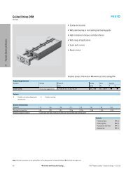
<strong>Pneumatic</strong>s<br />
Two-h<strong>and</strong> control block<br />
Cat. Can be used<br />
in higher<br />
PL<br />
category<br />
dC<br />
systems with<br />
additional<br />
measures<br />
Channels 1<br />
DIN EN 574 IIIA<br />
<strong>Safety</strong><br />
component to<br />
MD 2006/42/EC<br />
Yes<br />
Part no. Type<br />
576656 ZSB-1/8-B<br />
Logic Output<br />
Input Logic Output<br />
All specified values are maximum<br />
values, which can be achieved<br />
via correct operation <strong>and</strong><br />
interconnection of the SRP/CS.<br />
See the technical data of the individual products for detailed information.<br />
Please observe the legal information on page 76.<br />
1<br />
Circuit symbol<br />
2<br />
Notes<br />
The two h<strong>and</strong> control block is not<br />
a complete safety solution. It can<br />
be used as part of a solution.<br />
3<br />
1<br />
27
Switching between safety functions<br />
Sensor function When using two sensors with the<br />
correct diagnostics<br />
Cat. 3<br />
PL d<br />
dC Medium<br />
CCF >65 %<br />
Channels 2<br />
<strong>Safety</strong><br />
component to<br />
MD 2006/42/EC<br />
See the technical data of the individual products for detailed information.<br />
Please observe the legal information on page 76.<br />
28<br />
No<br />
Logic<br />
Logic<br />
Part no. Type<br />
575815 SAMH-S-N8-...-MK: Mounting kit (complete)<br />
575816 SAMH-S-N8-L-MK Mounting kit (complete)<br />
575817 SAMH-S-N8-S-SC Cover (spare part)<br />
575818 SAMH-S-N8-L-SC Cover (spare part)<br />
All specified values are maximum<br />
values, which can be achieved<br />
via correct operation of the<br />
component.<br />
Logic Output<br />
Notes<br />
Safe position sensing is possible<br />
when using two sensors with the<br />
correct diagnostics. It is then<br />
possible to switch between<br />
different safety functions.<br />
Switches are mechanically<br />
connected, are protected against<br />
manipulation <strong>and</strong> securely<br />
mounted.<br />
Sample application:<br />
In two-h<strong>and</strong> operation, the<br />
cylinder advances to an uncritical<br />
position where the position of<br />
the h<strong>and</strong>s no longer needs to be<br />
blocked. The two-h<strong>and</strong> switches<br />
can now be released.
Cylinder as a door drive<br />
Sensor function<br />
Cat. 3<br />
PL<br />
d<br />
dC Medium<br />
CCF >65 %<br />
Channels 2<br />
<strong>Safety</strong><br />
component to<br />
MD 2006/42/<br />
EC<br />
No<br />
Logic<br />
Logic<br />
When using two sensors with<br />
the correct diagnostics<br />
Part no. Type<br />
575815 SAMH-S-N8-S-MK Mounting kit (complete)<br />
575816 SAMH-S-N8-L-MK Mounting kit (complete)<br />
575817 SAMH-S-N8-S-SC Cover (spare part)<br />
575818 SAMH-S-N8-L-SC Cover (spare part)<br />
All specified values are maximum<br />
values, which can be achieved<br />
via correct operation of the<br />
component.<br />
See the technical data of the individual products for detailed information.<br />
Please observe the legal information on page 76.<br />
Logic Output<br />
Notes<br />
When using two sensors with the<br />
correct diagnostics, the position<br />
of the pneumatically actuated<br />
safety door can be reported<br />
reliably (SAMH-S) <strong>and</strong> directly via<br />
the drive. Additional sensing per<br />
EN 1088 is not necessary.<br />
The safety door is opened by a<br />
cylinder.<br />
If the door is open, the cylinder is<br />
not in the normal position. This is<br />
detected by the safe position<br />
encoders; the system remains at<br />
rest.<br />
Switches are protected against<br />
manipulation <strong>and</strong> securely<br />
mounted.<br />
29
Dual-pressure regulator<br />
Please observe the legal information on page 76.<br />
30<br />
Input Logic<br />
Input Logic Output<br />
Cat. Can be used in<br />
higher category<br />
PL<br />
systems with<br />
dC<br />
additional<br />
measures<br />
Channels 1<br />
<strong>Safety</strong><br />
No<br />
component to<br />
MD 2006/42/<br />
EC<br />
Part no. Type<br />
550588 LR-D-MINI-ZD-V24-SA<br />
567841 LR-D-MINI-ZD-V24-UK-SA<br />
Technical data<br />
Output pressure P2<br />
L 0.5 ... 7 bar<br />
L<br />
M<br />
Q<br />
Supply pressure P1<br />
1.5 ... 10 bar<br />
Flow rate<br />
up to 1300 l/min<br />
Temperature range<br />
-10 ... +60 °C<br />
Notes<br />
The dual-pressure regulator is<br />
not a complete safety solution. It<br />
can be used as part of a solution.<br />
Special features<br />
Diaphragm pressure regulator<br />
with two secondary venting ports<br />
for setting two different initial<br />
pressures in one device.<br />
Switching from the lower to the<br />
higher value occurs <strong>electric</strong>ally.<br />
Circuit symbol<br />
1 2
Input Logic<br />
Input<br />
<strong>Safety</strong> valve MS6-SV-E <strong>and</strong> MS6-SV-E-ASIS<br />
Cat. 4<br />
PL e<br />
dC high,<br />
integrated,<br />
internal sensing<br />
of the piston<br />
position<br />
Channels 2<br />
Certificate IFA<br />
<strong>Safety</strong><br />
component to<br />
MD 2006/42/EC<br />
Yes<br />
Part no. Type<br />
548713 MS6-SV<br />
562580 MS6-SV-1/2-E-10V24-AD1<br />
548715 MS6-SV-1/2-E-10V24-AG<br />
548717 MS6-SV-1/2-E-10V24-SO-AG<br />
552252 UOS-1<br />
Logic<br />
548719 Multi-pin plug NECA-S1G9-P9-MP1<br />
552703 Multi-pin plug NECA-S1G9-P9-MP3<br />
All specified values are maximum<br />
values, which can be achieved<br />
via correct operation of the<br />
component.<br />
573695 Multi-pin plug NECA-S1G9-P9-MP3-SA<br />
8001481 MS6-SV-1/2-E-ASIS-SO-AG<br />
See the technical data of the individual products for detailed information.<br />
Please observe the legal information on page 76.<br />
Technical data<br />
Voltage P<br />
24 V DC<br />
L<br />
Q<br />
M<br />
Operating pressure<br />
3.5 ... 10 bar<br />
Temperature range<br />
–10 ... +50 °C<br />
Flow rate (exhaust)<br />
up to 9000 l/min<br />
Possible special plug<br />
NECA-MP3-SA<br />
The NECA-MP3-SA permits<br />
activation of the MS6-SV with<br />
safety-related outputs. The<br />
enable signals EN1 <strong>and</strong> EN2 are<br />
galvanically isolated from the<br />
supply of the MS6-SV. Galvanic<br />
isolation is guaranteed via 2<br />
optocouplers.<br />
Circuit symbol<br />
12<br />
2<br />
1 3<br />
31
<strong>Safety</strong> valves MS6-SV-C <strong>and</strong> MS9-SV-C<br />
See the technical data of the individual products for detailed information.<br />
Please observe the legal information on page 76.<br />
32<br />
Input Logic<br />
Input Logic<br />
Output<br />
Cat. 1<br />
PL c<br />
dC Depending on<br />
diagnostics<br />
Channels 1<br />
<strong>Safety</strong> component to<br />
MD 2006/42/EC<br />
Part no. Type<br />
No<br />
8001469 MS6-SV-1/2-C-10V24<br />
570737 MS9-SV-G-C-V24-S-VS<br />
570739 MS9-SV-NG-C-V24-S-VS<br />
All specified values are maximum<br />
values, which can be achieved<br />
via correct operation of the<br />
component.<br />
Circuit symbol
On-off valve with piston position sensing<br />
Cat. Can be used in<br />
higher category<br />
PL<br />
systems with<br />
additional<br />
measures<br />
dC Switching<br />
position<br />
sensing<br />
Channels 1<br />
<strong>Safety</strong><br />
component to<br />
MD 2006/42/<br />
EC<br />
Input Logic<br />
Input Logic<br />
Output<br />
No<br />
Part no. Type<br />
Please observe the legal information on page 76.<br />
All specified values are maximum<br />
values, which can be achieved<br />
via suitable integration of the<br />
component into the entire<br />
system.<br />
533537 HEE-D-MIDI-...-SA207225<br />
548535 HEE-D-MAXI-...-SA217173<br />
Technical data<br />
Voltage<br />
24 V DC<br />
L<br />
Q<br />
Operating pressure<br />
2.5 ... 16 bar<br />
Temperature range<br />
–10 ... +60 °C<br />
P<br />
Notes<br />
The on-off valve with piston<br />
position sensing is not a<br />
complete safety solution. It can<br />
be used as part of a solution.<br />
Special features<br />
With solenoid coil, type<br />
MSSD-EB, plug design A, without<br />
socket, 3 voltage ranges can be<br />
selected, position sensing<br />
St<strong>and</strong>ard sensors with reed<br />
contacts can be used for a T-slot:<br />
type SME-8M, SMT-8M, SME-8,<br />
SMT-8<br />
Switching output contactless or<br />
via reed contacts<br />
Circuit symbol<br />
12<br />
2<br />
1 3<br />
33
34<br />
Input Logic<br />
Input<br />
Exhausting via non-return valves<br />
Cat. 3<br />
PL d<br />
dC Medium<br />
CCF >65 %<br />
Channels 2<br />
<strong>Safety</strong> component to<br />
MD 2006/42/EC<br />
No<br />
Logic<br />
All specified values are maximum<br />
values, which can be achieved<br />
via correct operation of the<br />
component.<br />
See the technical data of the individual products for detailed information.<br />
Please observe the legal information on page 76.<br />
Double-channel<br />
Always check that each channel<br />
in multi-channel <strong>solutions</strong> fulfils<br />
the safety function.<br />
Diagnostics<br />
Diagnostics for both channels<br />
must be carried out via software.<br />
Special features<br />
The non-return valves also need<br />
a differential pressure in order to<br />
exhaust. In the event of a fault, a<br />
residual pressure can remain in<br />
the system. The suitability of the<br />
set-up must be tested in the<br />
application.<br />
<strong>Safety</strong> function<br />
With this set-up, both cylinder<br />
chambers are exhausted via 2<br />
channels.
Input Logic<br />
Input<br />
Soft-start <strong>and</strong> exhaust valve type VABF<br />
Cat. 3<br />
PL d<br />
dC Switching position<br />
sensing<br />
CCF >65%<br />
Channels 2<br />
<strong>Safety</strong> component to<br />
MD 2006/42/EC<br />
No<br />
Part no. Type<br />
Logic<br />
557377 VABF-S6-1-P5A4-G12-4-1-P<br />
In combination<br />
with a second<br />
directional<br />
control valve Pressurising<br />
System protection for a<br />
restart<br />
See the technical data of the individual products for detailed information.<br />
Please observe the legal information on page 76.<br />
All specified values are<br />
maximum values, which can<br />
be achieved via correct<br />
operation of the<br />
component.<br />
Double-channel<br />
Always check that each channel<br />
in multi-channel <strong>solutions</strong> fulfils<br />
the safety function.<br />
<strong>Safety</strong> function<br />
The pneumatic diagram shown is<br />
only a basic example. The softstart<br />
valve function <strong>and</strong> further<br />
valve functions can be configured<br />
in the valve terminal VTSA. The<br />
pressure switch for monitoring<br />
the exhausted condition must be<br />
screwed on separately. The<br />
calculations of the PL must then<br />
be adjusted. The soft-start valve<br />
alone is not a complete safety<br />
solution.<br />
Protection against accidental<br />
activation of the manual override<br />
must be guaranteed in all<br />
operating modes.<br />
Diagnostics<br />
Diagnostics for both channels<br />
must be carried out via software<br />
in the customer's machine<br />
control system.<br />
35
VOFA – 5/2 <strong>Safety</strong> valves for presses<br />
Cat. 4<br />
PL e<br />
dC Switching position<br />
sensing with inductive<br />
PNP/NPN proximity<br />
sensor<br />
CCF >65%<br />
Channels 2<br />
Certificate IFA<br />
<strong>Safety</strong> component to<br />
MD 2006/42/EC<br />
See the technical data of the individual products for detailed information.<br />
Please observe the legal information on page 76.<br />
36<br />
Yes<br />
Part no. Designation Version<br />
All specified values are maximum<br />
values, which can be achieved<br />
via suitable integration of the<br />
component into the entire<br />
system.<br />
569819 VOFA-L26-T52-M-G14-1C1-APP Complete 2 x 5/2 control block, individual <strong>electric</strong>al<br />
connection, PNP sensor<br />
569820 VOFA-L26-T52-M-G14-1C1-ANP Complete 2 x 5/2 control block, individual <strong>electric</strong>al<br />
connection, NPN sensor<br />
Characteristic<br />
Characteristic<br />
Input Logic<br />
Input<br />
Logic<br />
“SP” in the order code Complete 2 x 5/2 control block, integration in valve<br />
terminal VTSA, PNP sensor<br />
“SN” in the order code Complete 2 x 5/2 control block, integration in valve<br />
terminal VTSA, NPN sensor<br />
Circuit symbol<br />
Diagnostics<br />
Diagnostics via evaluation of the<br />
actuation <strong>and</strong> feedback signals<br />
must be carried out in a safety<br />
switching device. A machine<br />
control system must be<br />
integrated for evaluation of the<br />
feedback signals.
Stopping with shut-off valves<br />
Cat.<br />
Input Logic<br />
Input<br />
3<br />
PL d<br />
dC Medium<br />
CCF >65%<br />
Channels 2<br />
<strong>Safety</strong> component<br />
to MD 2006/42/EC<br />
No<br />
Logic<br />
All specified values are maximum<br />
values, which can be achieved<br />
via correct operation of the<br />
component.<br />
See the technical data of the individual products for detailed information.<br />
Please observe the legal information on page 76.<br />
Notes<br />
Always check that each channel<br />
in multi-channel <strong>solutions</strong> fulfils<br />
the safety function sufficiently.<br />
The diagnostic evaluation must<br />
be performed by the software.<br />
The cylinder is stopped via<br />
compressed air. Therefore, the<br />
system contains energy stored as<br />
compressed air.<br />
Additional measures must be<br />
taken to be able to exhaust the<br />
cylinder chambers if necessary.<br />
If trapped compressed air can<br />
result in a danger, further<br />
measures are required.<br />
When the safe status is set, there<br />
are no additional air inflows or<br />
outflows.<br />
After the cylinder stops, it can<br />
move depending on the leakage<br />
of individual components. This<br />
can result in exhausting the<br />
cylinder chambers. Please also<br />
note this for the restart.<br />
37
38<br />
Input Logic<br />
Input<br />
Stopping with non-return valves<br />
Cat. 3<br />
PL d<br />
dC Medium<br />
CCF >65%<br />
Channels 2<br />
<strong>Safety</strong><br />
component to<br />
MD 2006/42/EC<br />
No<br />
Logic<br />
All specified values are maximum<br />
values, which can be achieved<br />
via correct operation of the<br />
component.<br />
See the technical data of the individual products for detailed information.<br />
Please observe the legal information on page 76.<br />
Notes<br />
Always check that each channel<br />
in multi-channel <strong>solutions</strong> fulfils<br />
the safety function.<br />
The diagnostic evaluation must<br />
be performed by the software.<br />
The cylinder is stopped via<br />
compressed air. Therefore, the<br />
system contains energy stored as<br />
compressed air. Additional<br />
measures must be taken to be<br />
able to exhaust the cylinder<br />
chambers.<br />
If trapped compressed air can<br />
result in a danger, further<br />
measures are required.<br />
Please note that the technical<br />
values of the components are<br />
complied with during braking via<br />
dynamic energy (e.g. via<br />
resulting pressure peaks).<br />
In the event of a fault of the 5/3way<br />
valve, compressed air can<br />
flow through the non-return valve<br />
HGL until the forces are<br />
balanced. That can lead to an<br />
increased overtravel time of the<br />
cylinder.<br />
After the cylinder stops, it can<br />
move depending on the leakage<br />
of individual components. This<br />
can result in exhausting the<br />
cylinder chambers. Please also<br />
note this for the restart.
ISO valve for lifting <strong>and</strong> rotary cylinders<br />
Order code<br />
Input Logic<br />
Input Logic<br />
Output<br />
Part no. Type Description<br />
Technical data<br />
Voltage P DC 24 V<br />
L<br />
Q<br />
M<br />
Pressure<br />
3 ... 10 bar<br />
Temperature range<br />
-5 ... +50 °C<br />
Flow rate<br />
1000 l/min<br />
560728 VSVA-B-P53AD-ZD-A1-1T1L Size 01, 5/3 mid-position, 1 port pressurised <strong>and</strong> 1 port<br />
exhausted, switching position 14 detented<br />
Description<br />
• For lifting <strong>and</strong> rotary cylinders<br />
in the automotive industry<br />
Application<br />
• Self-holding <strong>and</strong> subsequent<br />
pressure supply at both end<br />
positions<br />
• During the stroke, the cylinder<br />
must be kept under pressure in<br />
the event of an emergency (e.g.<br />
if a safety shut-off mat is<br />
stepped on).<br />
Circuit symbol<br />
Function Normal operation In the case of emergency off (<strong>electric</strong>al power is switched off) Actuation<br />
Retract clamping<br />
device<br />
Advance clamping<br />
device<br />
Clamping device in<br />
end position<br />
WV = way valve<br />
The 5/2-WV is used to<br />
retract the clamping<br />
device<br />
The 5/2-WV is used to<br />
retract the clamping<br />
device<br />
The end positions remain<br />
pressurised<br />
The clamping device remains under pressure in both chambers.<br />
5/3-WV normal position (14)<br />
5/2-WV 12 switched<br />
The clamping device remains under pressure in both chambers.<br />
5/3-WV normal position (14)<br />
5/2-WV 12 switched<br />
The pressure is maintained in the end positions<br />
5/3-WV 12 automatic locking<br />
5/2-WV 14 or 12 switched<br />
5/3-WV 12 switched<br />
(no automatic locking)<br />
5/2-WV 12 switched<br />
5/3-WV 12 switched<br />
(no automatic locking)<br />
5/2-WV 14 switched<br />
5/3-WV is switched to 12<br />
(automatic locking)<br />
5/2-WV switched to 14 or 12<br />
39
40<br />
Input Logic<br />
Input<br />
Mechanical <strong>and</strong> pneumatic stopping<br />
Cat. 3<br />
PL d<br />
dC Medium<br />
CCF >65%<br />
Channels 2<br />
<strong>Safety</strong><br />
component to<br />
MD 2006/42/EC<br />
No<br />
Logic<br />
All specified values are maximum<br />
values, which can be achieved<br />
via correct operation of the<br />
component.<br />
See the technical data of the individual products for detailed information.<br />
Please observe the legal information on page 76.<br />
Notes<br />
Always check that each channel<br />
in multi-channel <strong>solutions</strong> fulfils<br />
the safety function.<br />
The diagnostic evaluation must<br />
be performed by the software.<br />
After the cylinder stops, the<br />
cylinder chambers can vent<br />
depending on the leakage of the<br />
individual components. Please<br />
also note this for the restart.
Input Logic<br />
Input Logic<br />
Output<br />
Clamping cartridges<br />
Cat. Can be used<br />
PL<br />
in higher<br />
category<br />
dC<br />
systems with<br />
CCF<br />
additional<br />
measures<br />
Channels 1<br />
<strong>Safety</strong><br />
component to<br />
MD 2006/42/EC<br />
No<br />
Part no. Type<br />
178455 KP-10-350<br />
178456 KP-12-600<br />
178457 KP-16-1000<br />
178458 KP-20-1400<br />
178459 KP-20-2000<br />
Part no. dnc-kp Stroke<br />
163302 Ø 32 10 ... 2000<br />
163334 Ø 40 10 ... 2000<br />
163366 Ø 50 10 ... 2000<br />
163398 Ø 63 10 ... 2000<br />
163430 Ø 80 10 ... 2000<br />
163462 100 10 ... 2000<br />
163494 Ø 125 10 ... 2000<br />
All specified values are maximum<br />
values, which can be achieved<br />
via correct operation of the<br />
component.<br />
Part no. Type<br />
178460 KP-25-5000<br />
178461 KP-32-7500<br />
178452 KP-4-80<br />
178453 KP-6-180<br />
178454 KP-8-350<br />
See the technical data of the individual products for detailed information.<br />
Please observe the legal information on page 76.<br />
Notes<br />
The clamping cartridge is not a<br />
complete safety solution. It can<br />
be used as part of a solution.<br />
Function<br />
Part no. Type<br />
178465 KPE-10<br />
178466 KPE-12<br />
178467 KPE-16<br />
178468 KPE-20<br />
178469 KPE-25<br />
Circuit symbols<br />
• The piston rod can be held or<br />
clamped in any position.<br />
• The piston rod can also be held<br />
for extended periods,<br />
alternating loads, fluctuations<br />
or leakage.<br />
Part no. Type<br />
178470 KPE-32<br />
178462 KPE-4<br />
178463 KPE-6<br />
178464 KPE-8<br />
Part no. ADN-...-...-KP Stroke dnc-kp<br />
548206 Ø 20 10-300 KP-10-350<br />
548207 Ø 25 10-300 KP-10-350<br />
548208 Ø 32 10-400 KP-12-1000<br />
548209 Ø 40 10-400 KP-16-1400<br />
548210 Ø 50 10-400 KP-20-1400<br />
548211 Ø 63 10-400 KP-20-2000<br />
548212 Ø 80 10-500 KP-25-5000<br />
548213 Ø 100 10-500 KP-25-5000<br />
41
Mini-slide DGSL with clamping unit or end-position locking<br />
Cat. Can be used in higher<br />
category systems with<br />
PL<br />
additional measures<br />
dC<br />
CCF<br />
Channels 1<br />
<strong>Safety</strong> component to No<br />
MD 2006/42/EC<br />
See the technical data of the individual products for detailed information.<br />
Please observe the legal information on page 76.<br />
42<br />
Input Logic<br />
Input Logic<br />
Output<br />
Part no. Type<br />
543903 DGSL-6<br />
543904 DGSL-8<br />
543905 DGSL-10<br />
543906 DGSL-12<br />
543907 DGSL-16<br />
543908 DGSL-20<br />
543909 DGSL-25<br />
All specified values are maximum<br />
values, which can be achieved<br />
via correct operation of the<br />
component.<br />
Circuit symbols<br />
Clamping unit<br />
type code C<br />
Notes<br />
The clamping unit <strong>and</strong> the endposition<br />
locking are not complete<br />
safety <strong>solutions</strong>. They can be<br />
used as part of a solution.<br />
Clamping unit<br />
• For fixing the slide in any<br />
position<br />
• Frictional locking<br />
• Clamping via spring force,<br />
release via compressed air<br />
End-position locking<br />
• Mechanical locking when the<br />
end position is reached<br />
• Positive-locking<br />
• Locking via spring force,<br />
release via compressed air<br />
End-position lock type code E3
Input Logic<br />
Input Logic<br />
Output<br />
DGC with clamping unit<br />
Cat.<br />
Can be used in higher<br />
PL<br />
category systems with<br />
dC<br />
CCF<br />
additional measures<br />
Channels 1<br />
<strong>Safety</strong> component to<br />
MD 2006/42/EC<br />
No<br />
Clamping units for DGC axes<br />
Part no. Type<br />
532447 DGC-25-…-1H…-PN<br />
532448 DGC-32-…-1H…-PN<br />
532449 DGC-40-…-1H…-PN<br />
532450 DGC-50-…-1H…-PN<br />
544426 DGC-25-…-1H…-PN<br />
544427 DGC-32-…-1H…-PN<br />
544428 DGC-40-…-1H…-PN<br />
All specified values are maximum<br />
values, which can be achieved<br />
via correct operation <strong>and</strong><br />
interconnection of the SRP/CS.<br />
See the technical data of the individual products for detailed information.<br />
Please observe the legal information on page 76.<br />
Notes<br />
The clamping unit is not a<br />
complete safety solution. It can<br />
be used as part of a solution.<br />
Function<br />
Unpressurised state = Clamped<br />
state<br />
Pressurised = Opened state<br />
43
Cylinders with end-position locking<br />
Cat. Can be used in higher category<br />
systems with additional<br />
PL<br />
measures<br />
dC<br />
CCF<br />
Channels 1<br />
<strong>Safety</strong> component to No<br />
MD 2006/42/EC<br />
See the technical data of the individual products for detailed information.<br />
Please observe the legal information on page 76.<br />
44<br />
Input Logic<br />
Input Logic<br />
Output<br />
Part no. Type<br />
163302 DNC-32-EL<br />
163334 DNC-40-EL<br />
163366 DNC-50-EL<br />
163398 DNC-63-EL<br />
163430 DNC-80-EL<br />
163462 DNC-100-EL<br />
All specified values are maximum<br />
values, which can be achieved<br />
via correct operation of the<br />
component.<br />
Part no. Type<br />
548214 ADN-20-EL<br />
548215 ADN-25-EL<br />
548216 ADN-32-EL<br />
548217 ADN-40-EL<br />
548218 ADN-50-EL<br />
548219 ADN-63-EL<br />
548220 ADN-80-EL<br />
548221 ADN-100-EL<br />
Notes<br />
The mechanical lock is not a<br />
complete safety solution. It can<br />
be used as part of a solution.<br />
Function<br />
Mechanical locking when the end<br />
position is reached. The<br />
requirement for releasing is back<br />
pressure on the other side of the<br />
piston.<br />
• Positive-locking<br />
• Locking is automatically<br />
released when pressure is<br />
applied to the cylinder<br />
• End-position locking at one or<br />
both ends<br />
Circuit symbol
Input Logic<br />
Input Logic<br />
Output<br />
Brake unit DNCKE-S, KEC-S<br />
Cat.<br />
Can be used in higher<br />
PL<br />
category systems with<br />
dC<br />
CCF<br />
additional measures<br />
Channels 1<br />
<strong>Safety</strong> component to<br />
MD 2006/42/EC<br />
Yes, if IFA-certified<br />
Part no. Type Remark<br />
526482 DNCKE-40- -PPV-A<br />
526483 DNCKE-63- -PPV-A<br />
526484 DNCKE-100- -PPV-A<br />
538239 DNCKE-40- -PPV-A-S IFA-certified<br />
538240 DNCKE-63- -PPV-A-S IFA-certified<br />
538241 DNCKE-100- -PPV-A-S IFA-certified<br />
527492 KEC-16<br />
527493 KEC-20<br />
527494 KEC-25<br />
538242 KEC-16-S IFA-certified<br />
538243 KEC-20-S IFA-certified<br />
538244 KEC-25-S IFA-certified<br />
All specified values are maximum<br />
values, which can be achieved<br />
via correct operation of the<br />
component.<br />
See the technical data of the individual products for detailed information.<br />
Please observe the legal information on page 76.<br />
Notes<br />
The clamping unit <strong>and</strong> the endposition<br />
locking are not complete<br />
safety <strong>solutions</strong>. They can be<br />
used as part of a solution.<br />
As a holding device<br />
• Holding <strong>and</strong> clamping in the<br />
event of a power failure<br />
• Protection against pressure<br />
failure <strong>and</strong> pressure drop<br />
As a braking device<br />
• Braking or stopping<br />
movements<br />
• Interruption of a movement if a<br />
danger area is entered<br />
Circuit symbols<br />
45
Stop valve VL-2-1/4-SA<br />
Cat. Can be used<br />
PL<br />
in higher<br />
category<br />
dC<br />
systems with<br />
CCF<br />
additional<br />
measures<br />
Channels 1<br />
<strong>Safety</strong> component<br />
to MD 2006/42/EC<br />
No<br />
Please observe the legal information on page 76.<br />
46<br />
Input Logic<br />
Input Logic<br />
Output<br />
Part no. Type<br />
25025 VL-2-1/4-SA<br />
All specified values are maximum<br />
values, which can be achieved<br />
via correct operation of the<br />
component.<br />
Technical data<br />
Operating pressure<br />
L 0 ... 10 bar<br />
Q<br />
Temperature range<br />
-20 ... 80 °C<br />
Notes<br />
The stop valve is not a complete<br />
safety solution. It can be used as<br />
part of a solution.<br />
Circuit symbol
Input Logic<br />
Input<br />
Pilot air switching valve type VSVA<br />
Cat. 3<br />
PL d<br />
Part no. Type<br />
with<br />
two directional<br />
control valves<br />
dC Switching<br />
position sensing<br />
CCF > 65%<br />
Channels 2<br />
<strong>Safety</strong><br />
component to<br />
MD 2006/42/EC<br />
No<br />
Logic<br />
All specified values are maximum<br />
values, which can be achieved<br />
via correct operation of the<br />
component.<br />
573201 VSVA-B-M52-MZD-A2-1T1L-APX-0.5 5/2-way valve, width 18 mm, single solenoid, mechanical<br />
spring return, with switching position sensing via inductive<br />
sensor with PNP output <strong>and</strong> 0.5 m cable with 3-pin sensor<br />
push-in connector M12x1<br />
570850 VSVA-B-M52-MZD-A1-1T1L-APX-0.5 5/2-way valve, width 26 mm, single solenoid, mechanical<br />
spring return, with switching position sensing via inductive<br />
sensor with PNP output <strong>and</strong> 0.5 m cable with 4-pin sensor<br />
push-in connector M12x1<br />
573200 VABF-S4-2-S Vertical stacking manifold, width 26 mm, for connecting the<br />
pilot air from channel 1 to channel 14<br />
570851 VABF-S4-1-S Vertical stacking manifold, width 26 mm, for connecting the<br />
pilot air from channel 1 to channel 14<br />
8000033 SPBA-P2R-G18-W-M12-0.25X Mechanical pressure switch with a fixed switching point<br />
0.25 bar<br />
Sensing the pilot air in channel 14<br />
G1/8 threads, for screwing in VABF-S4-2-S or VABF-S4-1-S<br />
Sensor plug connector M12x1<br />
8000210 SPBA-P2R-G18-2P-M12-0.25X Electronic pressure switch with a fixed switching point 0.25 bar<br />
Sensing the pilot air in channel 14<br />
G1/8 threads, for screwing in VABF-S4-2-S or VABF-S4-1-S<br />
Sensor plug connector M12x1<br />
See the technical data of the individual products for detailed information.<br />
Please observe the legal information on page 76.<br />
Notes<br />
Always check that each channel<br />
in multi-channel <strong>solutions</strong> fulfils<br />
the safety function.<br />
Diagnostics must be carried out<br />
via software in the customer's<br />
machine control system.<br />
The pneumatic diagram shown is<br />
only a basic example.<br />
The "switchable pilot air"<br />
function <strong>and</strong> further valve<br />
functions can be configured in<br />
the valve terminal VTSA.<br />
The calculations of the PL must<br />
then be adjusted.<br />
The pilot air switching valve<br />
alone is not a complete safety<br />
solution. It can be used as part of<br />
a solution.<br />
Electrically reliable 2-channel<br />
deactivation must be<br />
guaranteed.<br />
47
Valves with switching position sensing<br />
Part no. Type<br />
See the technical data of the individual products for detailed information.<br />
Please observe the legal information on page 76.<br />
48<br />
Input Logic<br />
Input Logic<br />
Output<br />
Cat.<br />
PL<br />
dC Switching<br />
position<br />
sensing with<br />
inductive<br />
PNP/NPN<br />
proximity<br />
sensor<br />
CCF<br />
Channels 1<br />
<strong>Safety</strong> component No<br />
to MD 2006/42/EC<br />
All specified values are maximum<br />
values, which can be achieved<br />
via correct operation of the<br />
component.<br />
Description<br />
• Solenoid valves to<br />
ISO 15407-1, plug type C, for<br />
individual <strong>electric</strong>al connection<br />
• Solenoid valve to ISO 15407-2,<br />
for use with valve terminal<br />
VTSA<br />
• Valve function: 5/2-way valve<br />
with spring return<br />
• ISO size 1, other sizes on<br />
request<br />
• Width: 26 mm<br />
• Normal position of the piston<br />
spool is monitored by a<br />
proximity sensor<br />
• For control architectures in<br />
higher categories<br />
• Proximity sensor with M8<br />
connection<br />
Notes<br />
The switching position sensing<br />
allows higher diagnostic<br />
coverage to be achieved for the<br />
valves.<br />
Circuit symbol<br />
560723 VSVA-B-M52-MZD-A1-1T1L-APC Size 01, 5/2 single solenoid, return via mech. spring, plug-in valve, with PNP sensor <strong>and</strong> cable<br />
560724 VSVA-B-M52-MZD-A1-1T1L-APP Size 01, 5/2 single solenoid, return via mech. spring, plug-in valve, with PNP sensor <strong>and</strong> plug M8<br />
560725 VSVA-B-M52-MZ-A1-1C1-APC Size 01, 5/2 single solenoid, return via mech. spring, Cnomo valve, with PNP sensor <strong>and</strong> cable<br />
560726 VSVA-B-M52-MZ-A1-1C1-APP Size 01, 5/2 single solenoid, return via mech. spring, Cnomo valve, with PNP sensor <strong>and</strong> plug M8<br />
560742 VSVA-B-M52-MZD-A1-1T1L-APC Size 01, 5/2 single solenoid, return via mech. spring, plug-in valve, with NPN sensor <strong>and</strong> cable<br />
560743 VSVA-B-M52-MZD-A1-1T1L-ANP Size 01, 5/2 single solenoid, return via mech. spring, plug-in valve, with NPN sensor <strong>and</strong> plug M8<br />
560744 VSVA-B-M52-MZ-A1-1C1-APC Size 01, 5/2 single solenoid, return via mech. spring, Cnomo valve, with NPN sensor <strong>and</strong> cable<br />
560745 VSVA-B-M52-MZ-A1-1C1-ANP Size 01, 5/2 single solenoid, return via mech. spring, Cnomo valve, with NPN sensor <strong>and</strong> cable
Valve with switching position sensing<br />
Order code<br />
Input Logic<br />
Input<br />
Cat. Can be used in<br />
PL<br />
higher category<br />
systems with<br />
dC<br />
additional<br />
CCF<br />
Channels<br />
measures<br />
<strong>Safety</strong><br />
component to<br />
MD 2006/42/EC<br />
No<br />
Part no. Type<br />
Logic<br />
185994 MDH-5/2-D1-FR-S-C-A-SA27102<br />
188005 MDH-5/2-D2-FR-S-C-A-SA23711<br />
188006 MDH-5/2-D3-FR-S-C-A-SA23712<br />
Output<br />
Output<br />
See the technical data of the individual products for detailed information.<br />
Please observe the legal information on page 76.<br />
Technical data<br />
Voltage P 24 V DC<br />
L<br />
Q<br />
M<br />
Pressure<br />
3 ... 10 bar<br />
Temperature range<br />
-10 ... +50 °C<br />
Flow rate<br />
1200 ... 4500 l/min<br />
Circuit symbol<br />
Description<br />
• The position of the piston<br />
spool is sensed directly<br />
• Senses position, not pressure<br />
• Suitable for circuits with a<br />
higher diagnostic coverage<br />
• Suitable for higher category<br />
circuits to DIN EN ISO 13849-1<br />
Sensors from <strong>Festo</strong><br />
St<strong>and</strong>ard sensors with reed<br />
contacts can be used for a T-slot:<br />
Type SME-8M, SMT-8M, SME-8,<br />
SMT-8<br />
• Switching output contactless<br />
or via reed contacts<br />
• Wide range of mounting <strong>and</strong><br />
connection options<br />
• Heat <strong>and</strong> corrosion-resistant<br />
versions<br />
• Copper <strong>and</strong> PTFE-free versions<br />
Please note: sensors must be<br />
ordered separately.<br />
49
Tamper-proof flow control valve GRLA-…-SA<br />
Cat. Can be used in higher<br />
category systems with<br />
PL<br />
additional measures<br />
dC<br />
CCF<br />
Channels 1<br />
<strong>Safety</strong> component to<br />
No<br />
MD 2006/42/EC<br />
See the technical data of the individual products for detailed information.<br />
Please observe the legal information on page 76.<br />
50<br />
Input Logic<br />
Input Logic<br />
Output<br />
Part no. Type<br />
539717 GRLA-M5-B-SA<br />
539661 GRLA-1/8-B-SA<br />
539662 GRLA-1/4-B-SA<br />
539715 GRLA-3/8-B-SA<br />
539716 GRLA-1/2-B-SA<br />
539714 GRLA-3/4-B-SA<br />
All specified values are maximum<br />
values, which can be achieved<br />
via correct operation of the<br />
component.<br />
Notes<br />
The flow control valve is not a<br />
complete safety solution. It can<br />
be used as part of a solution.<br />
Function<br />
• Selection of a specified flow<br />
rate<br />
• Secured with a spring pin<br />
against readjustment of the<br />
volumetric flow rate.<br />
Circuit symbol<br />
2<br />
1
Input Logic<br />
Input Logic<br />
Output<br />
Shut-off valve<br />
Cat. Can be used in higher<br />
PL<br />
category systems with<br />
dC<br />
CCF<br />
additional measures<br />
Channels 1<br />
<strong>Safety</strong> component to<br />
MD 2006/42/EC<br />
No<br />
Part no. Type<br />
197136 HE-G1-LO<br />
197135 HE-G3/4-LO<br />
197134 HE-G1/2-LO<br />
197133 HE-G3/8-LO<br />
197132 HE-N1-LO-NPT<br />
197131 HE-N3/4-LO-NPT<br />
197130 HE-N1/2-LO-NPT<br />
197129 HE-N3/8-LO-NPT<br />
All specified values are maximum<br />
values, which can be achieved via<br />
correct operation of the<br />
component.<br />
See the technical data of the individual products for detailed information.<br />
Please observe the legal information on page 76.<br />
Notes<br />
The shut-off valve is not a<br />
complete safety solution. It can<br />
be used as part of a solution.<br />
Function<br />
• Switching off <strong>and</strong> venting<br />
pneumatic systems<br />
• Can be shut off up to 6 times<br />
• Free of PWIS<br />
The shut-off valve must not be<br />
used as an emergency stop valve<br />
Circuit symbol<br />
51
ISO valve for pneumatic manual clamping devices<br />
52<br />
Input Logic<br />
Input Logic<br />
Output<br />
Cat. 2<br />
PL d<br />
dC Low<br />
CCF >65%<br />
Channels 1<br />
<strong>Safety</strong> component to<br />
MD 2006/42/EC<br />
No<br />
Part no. Type<br />
All specified values are maximum<br />
values, which can be achieved<br />
via correct operation of the<br />
component.<br />
Technical data<br />
Voltage<br />
P DC 24 V<br />
L<br />
Q<br />
M<br />
Pressure<br />
3 ... 10 bar<br />
Temperature range<br />
-5 ... +50 °C<br />
Flow rate<br />
1000 l/min<br />
560727 VSVA-B-P53ED-ZD-A1-1T1L Size 01, 5/3 mid-position exhausted,<br />
switching position 14 detenting<br />
Function Normal operation<br />
Clamping device is<br />
closed manually<br />
Clamping device is in<br />
the end position<br />
(metal sheet is<br />
clamped)<br />
Clamping device<br />
opens automatically<br />
The 5/2-WV is used to retract<br />
the clamping device<br />
The clamping device is<br />
advanced via the 5/2-WV<br />
In the case of emergency off<br />
(<strong>electric</strong>al power is switched off) Actuation<br />
Unpressurised Valve is in the mid-position<br />
Force supported by air pressure<br />
(self-locking); valve remains in<br />
position 12<br />
Coil 12 is switched<br />
<strong>Pneumatic</strong>ally operated Valve returns to the mid-position Coil 14 is switched<br />
Description<br />
<strong>Pneumatic</strong> manual clamping<br />
device for use in car body<br />
construction (inserting stations)<br />
Circuit symbol
Pressure zones for valve terminal type 44 VTSA<br />
The illustration shows an<br />
example of how three pressure<br />
zones are built up <strong>and</strong> connected<br />
with duct separation,<br />
with internal pilot air.<br />
See the technical data of the individual products for detailed information.<br />
Please observe the legal information on page 76.<br />
Creating pressure zones <strong>and</strong><br />
separating exhaust air<br />
• With VTSA, pressure zones with<br />
different working pressures<br />
can be created<br />
• A pressure zone can be created<br />
by separating the internal<br />
supply ducts between the<br />
series manifolds using<br />
appropriate duct separation<br />
• Compressed air supply <strong>and</strong><br />
exhaust via the supply plate<br />
• Free positioning of the supply<br />
plates <strong>and</strong> separating seals in<br />
the VTSA<br />
• Channel separations integrated<br />
ex-works as per the order,<br />
differences can be indicated<br />
via the coding system for<br />
assembled valve terminals<br />
VTSA with CPX terminal<br />
connection<br />
• Up to 16 pressure zones<br />
possible with VTSA (only with<br />
size 1, ISO 5599-2, up to 32<br />
pressure zones are possible)<br />
Further examples of compressed<br />
air supply <strong>and</strong> pilot air via an<br />
end plate<br />
• Internal pilot air, ducted<br />
exhaust air/silencer<br />
• External pilot air, silencer/<br />
ducted exhaust air<br />
Reliable exhausting of valves or<br />
pressure zones<br />
If used together with the MS6-SV<br />
valve, certain areas can be<br />
exhausted safely whilst the<br />
pressure is retained for specific<br />
valves or pressure zones. This is<br />
a common requirement for<br />
protective circuits.<br />
53
Pressure zones for valve terminal type 32 MPA<br />
The illustration shows an<br />
example of how three pressure<br />
zones are built up <strong>and</strong> connected<br />
with separating seals, with<br />
external pilot air supply.<br />
Please observe the legal information on page 76.<br />
54<br />
Creating pressure zones <strong>and</strong><br />
separating exhaust air<br />
• With MPA, pressure zones with<br />
different working pressures<br />
can be easily created.<br />
• A pressure zone can be<br />
created by separating the<br />
internal supply ducts between<br />
the sub-bases, with a<br />
corresponding separating seal<br />
or via a separator integrated<br />
into the sub-base (code I)<br />
• Compressed air supply <strong>and</strong><br />
exhaust via supply plate<br />
• Free positioning of the supply<br />
plates <strong>and</strong> separating seals in<br />
MPA with CPX <strong>and</strong> MPM<br />
(multiple connector plate)<br />
• Separating seals integrated<br />
ex-works as per the order,<br />
differences can be indicated<br />
via the coding system for<br />
assembling valve terminals<br />
MPA with CPX terminal<br />
connection<br />
Example of pressure zones<br />
• Up to 8 pressure zones<br />
possible with MPA <strong>and</strong> CPX<br />
Further examples of compressed<br />
air supply <strong>and</strong> pilot air supply<br />
• External pilot supply air,<br />
flat plate silencer<br />
• Internal pilot air supply,<br />
ducted exhaust air<br />
• External pilot air supply,<br />
ducted exhaust air<br />
Reliable exhausting of valves or<br />
pressure zones<br />
If used together with the MS6-SV<br />
valve, certain areas can be<br />
exhausted safely whilst the<br />
pressure is retained for specific<br />
valves or pressure zones. This is<br />
a common requirement for<br />
protective circuits.
Servopneumatics<br />
<strong>Safety</strong> function for servopneumatics<br />
Cat. 2 3<br />
PL d d<br />
dC Medium Medium<br />
CCF >65% >65%<br />
Channels 1 2<br />
<strong>Safety</strong> component to<br />
MD 2006/42/EC<br />
Part no. Designation<br />
No No<br />
See the technical data of the individual products for detailed information.<br />
Please observe the legal information on page 76.<br />
All specified values are maximum<br />
values, which can be achieved<br />
via correct operation of the<br />
component.<br />
550171 VPWP-6-L-5-… Proportional valve, component of the servopneumatic system as a<br />
first channel<br />
534546<br />
161109<br />
VSVA-B-M52-MZH-A1-1R5L<br />
NAS-1/4-01-VDMA<br />
5/2 single solenoid switching valve, with spring return <strong>and</strong><br />
auxiliary pilot air as a 2nd channel. The size (flow rate) is based on<br />
the proportional valve.<br />
535413 DNCI-50-500-P-A St<strong>and</strong>ard cylinder with displacement encoder<br />
542897<br />
Input Logic<br />
Input<br />
Switching off power<br />
Logic<br />
SDE5-D10-FP-Q6E-P-M8<br />
Pressure switch for diagnostics of the emergency stop valves<br />
(VSVA)<br />
9517 GRU-1/4-B Flow control/silencer for defined exhausting of the cylinder<br />
153464 H-QS-8 Non-return valve<br />
Functions<br />
• Protection against unexpected<br />
start-up (2-channel)<br />
• Venting (1-channel)<br />
• Stop category: "0"<br />
(EN 60204-1)<br />
• Compressed air supply not<br />
deactivated<br />
Notes<br />
• This circuit is only<br />
recommended for horizontal<br />
axes.<br />
• The axis can still move after an<br />
emergency stop. The overtravel<br />
depends on the current speed<br />
<strong>and</strong> the moving mass at the<br />
time of the request.<br />
• On restart, the drive can move,<br />
depending on the start<br />
conditions.<br />
• Use of a braking/clamping<br />
unit, together with the<br />
servopneumatic controller, can<br />
prevent a movement on restart.<br />
55
<strong>Safety</strong> function for servopneumatics<br />
Mechanical <strong>and</strong> pneumatic stopping<br />
Cat. 3<br />
PL d<br />
dC Medium<br />
CCF >65%<br />
Channels 3<br />
<strong>Safety</strong><br />
component to<br />
MD 2006/42/EC<br />
56<br />
No<br />
Part no. Designation Description<br />
All specified values are maximum<br />
values, which can be achieved<br />
via correct operation of the<br />
component.<br />
550171 VPWP-6-L-5-… Proportional valve, component of the servopneumatic system as a first<br />
channel<br />
534546<br />
161109<br />
Input Logic<br />
Input<br />
Logic<br />
VSVA-B-M52-MZH-A1-1R5L<br />
NAS-1/4-01-VDMA<br />
5/2 single solenoid switching valve with spring return <strong>and</strong> auxiliary pilot<br />
air <strong>and</strong> switching position sensing as a second channel.<br />
The size (flow rate) is based on the proportional valve<br />
173124 MEH-3/2-1/8-B 3/2 single solenoid switching valve, with spring return<br />
526483 DNCKE-63-250-PPV-A St<strong>and</strong>ard cylinder with clamping unit,<br />
displacement encoder attached externally<br />
542897 SDE5-D10-FP-Q6E-P-M8 Pressure switch for monitoring the emergency stop valves VSVA <strong>and</strong> the<br />
clamping function<br />
11689 H-QS-8 Non-return valve<br />
with displacement<br />
encoder<br />
See the technical data of the individual products for detailed information.<br />
Please observe the legal information on page 76.<br />
Properties<br />
• Protection against unexpected<br />
start-up (2-channel)<br />
• <strong>Safety</strong> measure: stopping<br />
(2-channel)<br />
• Stop category: "1"<br />
• Compressed air supply not<br />
deactivated<br />
Notes<br />
• Recommended for vertical axes<br />
• When the emergency stop is<br />
activated, the compressed air<br />
remains trapped in the drive;<br />
the drive is not free of<br />
compressed air. The braking<br />
unit, together with the<br />
servopneumatic controller, can<br />
prevent a movement on restart.<br />
• If only one clamping unit/<br />
cartridge is used, the axis must<br />
be at a st<strong>and</strong>still before it is<br />
clamped. This st<strong>and</strong>still can be<br />
generated via a STOP signal<br />
with the servopneumatic<br />
controller. The emergency stop<br />
valves VSVA are then<br />
deactivated with a time delay.
<strong>Safety</strong> function for servopneumatics<br />
<strong>Pneumatic</strong> stopping<br />
Cat. 3<br />
PL d<br />
dC High<br />
CCF >65%<br />
Channels 2<br />
<strong>Safety</strong><br />
component to<br />
MD 2006/42/EC<br />
No<br />
All specified values are maximum<br />
values, which can be achieved<br />
via correct operation of the<br />
component.<br />
Part no. Designation Description<br />
See the technical data of the individual products for detailed information.<br />
Please observe the legal information on page 76.<br />
Properties<br />
• Protection against unexpected<br />
start-up (2-channel)<br />
• <strong>Safety</strong> measure: stopping the<br />
movement (2-channel)<br />
• Stop category: "1"<br />
• Compressed air supply is<br />
switched off (2-channel)<br />
550171 VPWP-6-L-5-… Proportional valve, component of the servopneumatic system as a<br />
first channel<br />
534546<br />
161109<br />
Input Logic<br />
Input<br />
Logic<br />
VSVA-B-M52-MZH-A1-1R5L<br />
NAS-1/4-01-VDMA<br />
5/2 single solenoid switching valve with spring return <strong>and</strong><br />
auxiliary pilot air <strong>and</strong> switching position sensing as a second<br />
channel.<br />
The size (flow rate) is based on the proportional valve<br />
548713 MS6-SV-1/2-E-10V24-SO Soft-start/quick exhaust valve with 2-channel self monitoring <strong>and</strong><br />
performance level e<br />
544428 DGCI-40-750-P-A Rodless linear drive with displacement encoder<br />
11689 H-QS-8 Non-return valve<br />
Notes<br />
• This set-up can be used for<br />
horizontal <strong>and</strong> vertical axes.<br />
• When the emergency stop is<br />
activated, the compressed air<br />
remains trapped in the drive;<br />
the drive is not free of<br />
compressed air.<br />
• It is characteristic of pneumatic<br />
systems that the trapped<br />
compressed air in the cylinder<br />
does not lead directly to a<br />
st<strong>and</strong>still of the axis. The<br />
overtravel depends on the<br />
current speed <strong>and</strong> the moving<br />
mass.<br />
• On restart, the drive can move,<br />
depending on the start<br />
conditions.<br />
• Use of a braking/clamping<br />
unit, together with the<br />
servopneumatic controller, can<br />
prevent a movement on restart.<br />
57
<strong>Safety</strong> function for servopneumatics<br />
Cat. 3<br />
PL d<br />
dC High<br />
CCF >65%<br />
Channels 2<br />
<strong>Safety</strong><br />
component to<br />
MD 2006/42/EC<br />
See the technical data of the individual products for detailed information.<br />
Please observe the legal information on page 76.<br />
58<br />
No<br />
All specified values are maximum<br />
values, which can be achieved<br />
via correct operation of the<br />
component.<br />
Part no. Designation Description<br />
Properties<br />
• Protection against unexpected<br />
start-up (2-channel)<br />
• <strong>Safety</strong> measure: stopping the<br />
movement (2-channel)<br />
• Stop category: "1"<br />
• Compressed air supply is<br />
switched off (2-channel)<br />
550171 VPWP-6-L-5-… Proportional valve, component of the servopneumatic system as<br />
a first channel<br />
560726<br />
161109<br />
Input Logic<br />
Input<br />
Logic<br />
VSVA-B-M52-MZ-A1-1C1-APP<br />
NAS-1/4-01-VDMA<br />
5/2 single solenoid switching valve with spring return <strong>and</strong><br />
auxiliary pilot air <strong>and</strong> switching position sensing as a second<br />
channel.<br />
The size (flow rate) is based on the proportional valve<br />
544428 DGCI-40-750-… Rodless linear drive with displacement encoder<br />
Notes<br />
• This set-up can be used for<br />
horizontal <strong>and</strong> vertical axes.<br />
• When the emergency stop is<br />
activated, the compressed air<br />
remains trapped in the drive;<br />
the drive is not free of<br />
compressed air.<br />
• It is characteristic of pneumatic<br />
systems that the trapped<br />
compressed air in the cylinder<br />
does not lead directly to a<br />
st<strong>and</strong>still of the axis.<br />
The overtravel depends on the<br />
current speed <strong>and</strong> the moving<br />
mass.<br />
• On restart, the drive can move,<br />
depending on the start<br />
conditions. If the valves VSVA<br />
<strong>and</strong> VPWP are switched or<br />
activated at the same time, this<br />
movement can be minimised.<br />
• Use of a braking/clamping<br />
unit, together with the<br />
servopneumatic controller, can<br />
prevent a movement on restart.
<strong>Safety</strong> function for servopneumatics<br />
<strong>Pneumatic</strong> reversing<br />
Part no. Designation Description<br />
550171 VPWP-6-L-5-… Proportional valve, component of the servopneumatic<br />
system as a first channel<br />
534546<br />
161109<br />
Input Logic<br />
Input<br />
Cat. 2 3<br />
PL d d<br />
dC Medium Medium<br />
CCF >65% >65%<br />
Channels 1 2<br />
<strong>Safety</strong><br />
component to<br />
MD 2006/42/EC<br />
Logic<br />
No No<br />
VSVA-B-M52-MZH-A1-1R5L<br />
NAS-1/4-01-VDMA<br />
535413 DNCI-50-500-P-A St<strong>and</strong>ard cylinder<br />
See the technical data of the individual products for detailed information.<br />
Please observe the legal information on page 76.<br />
5/2 single solenoid switching valve, with spring return <strong>and</strong><br />
auxiliary pilot air as a 2nd channel. The size (flow rate) is<br />
based on the proportional valve.<br />
542897 SDE5-D10-FP-Q6E-P-M8 Pressure switch for diagnostics of the emergency stop<br />
valves (VSVA)<br />
193973 GR0-QS-6 Flow control valve for regulating the repositioner speed<br />
11689 H-QS-8 Non-return valve<br />
All specified values are maximum<br />
values, which can be achieved<br />
via correct operation <strong>and</strong><br />
interconnection of the SRP/CS.<br />
Properties<br />
• Protection against unexpected<br />
start-up (2-channel)<br />
• <strong>Safety</strong> measure: reversing<br />
(1-channel)<br />
• <strong>Safety</strong> measure: travel at<br />
reduced speed (1-channel)<br />
• Compressed air supply not<br />
deactivated<br />
Notes<br />
• Can also be used for vertical<br />
axes<br />
• If an emergency stop is<br />
activated, the drive is<br />
pressurised.<br />
• On restart, the drive can move,<br />
depending on the start<br />
conditions.<br />
• Use of a braking/clamping<br />
unit, together with the<br />
servopneumatic controller, can<br />
prevent a movement on restart.<br />
59
60<br />
Electrical components<br />
Input Logic Output<br />
Input Logic Output<br />
EGC – linear measuring system<br />
Only linear<br />
measuring<br />
system<br />
Cat. 2 4<br />
PL d e<br />
dC Medium High<br />
CCF >65% >65%<br />
Channels 1 2<br />
<strong>Safety</strong><br />
component to<br />
MD 2006/42/EC<br />
No No<br />
With 2nd<br />
measuring system<br />
(encoder) in the<br />
servo motor<br />
The linear measuring system is a component of the modular axis<br />
system <strong>and</strong> can be configured in the following axes:<br />
Toothed belt axes Spindle axes<br />
Part no. Type<br />
556813 EGC-70-…-M…<br />
556814 EGC-80-…-M…<br />
556815 EGC-120-…-M…<br />
556817 EGC-185-…-M…<br />
See the technical data of the individual products for detailed information.<br />
Please observe the legal information on page 76.<br />
All specified values are maximum<br />
values, which can be achieved<br />
via correct operation <strong>and</strong><br />
interconnection of the SRP/CS.<br />
The selected SRP/CS must be<br />
suitable for the use <strong>and</strong> safetyrelated<br />
evaluation of st<strong>and</strong>ard<br />
encoders.<br />
Part no. Type<br />
556807 EGC-70-…-M…<br />
556808 EGC-80-…-M…<br />
556809 EGC-120-…-M…<br />
556811 EGC-185-…-M…<br />
Comment<br />
The linear measuring system is<br />
not a complete safety solution. It<br />
can be used as part of a solution.<br />
A monitoring system is always<br />
required in that case.<br />
A 2-channel solution is possible<br />
together with a motor encoder<br />
<strong>and</strong> a suitable safety switching<br />
device.<br />
Position of the slide is measured<br />
directly – without additional<br />
mechanical influences.<br />
Measuring directly on the<br />
carriage increases absolute<br />
accuracy.
Input Logic<br />
Input<br />
EGC – clamping unit<br />
Cat. Can be used in higher Can be used in higher<br />
PL<br />
dC<br />
CCF<br />
category systems with<br />
additional measures<br />
category systems with<br />
additional measures<br />
Channels 1 2<br />
<strong>Safety</strong><br />
component to<br />
MD 2006/42/EC<br />
No No<br />
Clamping unit for EGC axles<br />
Part no. Type<br />
Logic<br />
1-channel 2-channel<br />
Toothed belt axes Spindle axes<br />
556814 EGC-80-…-…H…-PN<br />
556815 EGC-120-…-…H…-PN<br />
556817 EGC-185-…-…H…-PN<br />
See the technical data of the individual products for detailed information.<br />
Please observe the legal information on page 76.<br />
All specified values are maximum<br />
values, which can be achieved<br />
via correct operation <strong>and</strong><br />
interconnection of the SRP/CS.<br />
Part no. Type<br />
556808 EGC-80-…-…H…-PN<br />
556809 EGC-120-…-…H…-PN<br />
556811 EGC-185-…-…H…-PN<br />
Comment<br />
The linear measuring system is<br />
not a complete safety solution. It<br />
can be used as part of a solution.<br />
A 2-channel solution is possible<br />
together with a motor encoder<br />
<strong>and</strong> a suitable safety switching<br />
device.<br />
The position of the slide is<br />
measured directly – without<br />
additional mechanical influences.<br />
Measuring directly on the<br />
carriage increases absolute<br />
accuracy.<br />
61
<strong>Safety</strong> module CAMC-G-S1<br />
Cat. 4<br />
PL e<br />
dC High<br />
CCF >65%<br />
Channels 2<br />
<strong>Safety</strong><br />
component acc.<br />
to MD 2006/42/<br />
EC<br />
See the technical data of the individual products for detailed information.<br />
Please observe the legal information on page 76.<br />
73.<br />
62<br />
Input Logic Output<br />
Input Logic Output<br />
STO<br />
v<br />
0<br />
Yes<br />
Part no. Type<br />
1501330 CAMC-G-S1<br />
t<br />
All specified values are maximum<br />
values, which can be achieved<br />
via correct operation of the<br />
component.<br />
Comment<br />
The safety module CAMC-G-S1 is<br />
a plug-in card for the motor<br />
controller CMMP-AS-_-M3 <strong>and</strong><br />
integrates the safety function of<br />
safe torque off (STO) up to PL e,<br />
category 4, in the motor<br />
controller.<br />
With an external safety switching<br />
device, it is possible to<br />
implement the safe stop 1 safety<br />
function (SS1), i.e. decelerate<br />
<strong>and</strong> then safe torque off (STO)<br />
with a time delay, in a<br />
straightforward manner.
Input Logic Output<br />
Input Logic Output<br />
<strong>Safety</strong> module CAMC-G-S3<br />
Cat. 4<br />
PL e<br />
dC High<br />
CCF >65%<br />
Channels 2<br />
<strong>Safety</strong> component acc. to<br />
MD 2006/42/EC<br />
STO<br />
v<br />
0<br />
Yes<br />
Part no. Type<br />
1501331 CAMC-G-S3<br />
v<br />
s<br />
0<br />
SS2<br />
See the technical data of the individual products for detailed information.<br />
Please observe the legal information on page 76.<br />
t<br />
t<br />
SLS<br />
v<br />
0<br />
v<br />
s<br />
0<br />
t<br />
SOS<br />
t<br />
SS1 STO<br />
v<br />
s<br />
0 t<br />
v s<br />
SSR SLP<br />
t t<br />
v<br />
M<br />
t<br />
SBC<br />
Comment<br />
The safety module CAMC-G-S3<br />
has been developed so that<br />
functional safety can be<br />
integrated into the motor<br />
controllers of the CMMP-AS-_-M3<br />
series. This safety module<br />
integrates the following safety<br />
<strong>and</strong> logic functions in the motor<br />
controller:<br />
All specified values are maximum<br />
values, which can be achieved<br />
via correct operation of the<br />
component.<br />
• Safe torque off, STO<br />
• Safe stop 1, SS1<br />
• Safe operation stop, SOS<br />
• Safe stop 2, SS2<br />
• Safely limited speed, SLS<br />
• Safe speed range, SSR<br />
• Safe brake control, SBC<br />
• Safe speed monitor, SSM<br />
• Safe logic function (additional<br />
logic function, ALF), e.g. AND,<br />
OR, NOT, etc.<br />
Using this plug-in card makes it<br />
possible to dispense with<br />
external safety switching devices<br />
in many applications, resulting in<br />
simplified wiring, reduced<br />
number of components <strong>and</strong><br />
lower costs of the system<br />
solution.<br />
63
<strong>Safety</strong> module CMGA<br />
All specified values are maximum<br />
values, which can be achieved<br />
via correct operation of the<br />
component.<br />
Cat. 4<br />
PL e<br />
dC High<br />
CCF >65%<br />
Channels 2<br />
<strong>Safety</strong> component to<br />
MD 2006/42/EC<br />
See the technical data of the individual products for detailed information.<br />
Please observe the legal information on page 76.<br />
64<br />
Input Logic Output<br />
Input Logic Output<br />
Yes<br />
Part no. Type<br />
SS1 STO SS2 SOS SOS<br />
v<br />
s<br />
v<br />
s<br />
v<br />
s<br />
0 t 0 t 0 t<br />
1680823 CMGA-B1-M0-L0-A0<br />
1680824 CMGA-B1-M1-L1-A0<br />
1680825 CMGA-B1-M2-L2-A0<br />
1680826 CMGA-E1<br />
1680827 CMGA-E1-PB<br />
1680828 CMGA-E1-CO<br />
1680829 CMGA-E1-DN<br />
SLS<br />
v<br />
0<br />
t<br />
s<br />
SLP<br />
t<br />
v<br />
M<br />
v<br />
M<br />
t<br />
SBC<br />
t<br />
SBC<br />
Comment<br />
The safety system CMGA permits<br />
one or two-channel monitoring of<br />
safety comm<strong>and</strong> devices (e.g.<br />
emergency stop switch, safety<br />
door, light curtain, operating<br />
mode selection switch, etc.), of<br />
speed <strong>and</strong> position sensors, their<br />
signal processing as well as one<br />
or two-channel triggering of a<br />
suitable safety measure.<br />
This is a programmable system,<br />
which means it can be optimally<br />
adapted to the corresponding<br />
safety-oriented application.<br />
Programming examples in these<br />
<strong>guidelines</strong> allow the complexity<br />
of this programmable safety<br />
system to be reduced to<br />
downloading a user program,<br />
<strong>and</strong> wiring.<br />
<strong>Safety</strong> functions:<br />
• Safe stop 1 (SS1, decelerate<br />
<strong>and</strong> then safe torque off (STO))<br />
• Safe stop 2 (SS2, delay <strong>and</strong><br />
then safe operating stop<br />
(SOS))<br />
• Safe operating stop (SOS)<br />
• Safely limited speed (SLS)<br />
• Safely-limited position (SLP)<br />
• Safe brake control (SBC)<br />
• Safe direction (SDI)<br />
• Safe speed monitor (SSM)<br />
• Safely-limited increment (SLI)<br />
• Position deviation muting<br />
(PDM)<br />
• Encoder status (ECS)<br />
• Safely-limited acceleration<br />
(SLA)<br />
• Safe acceleration range (SCA)<br />
• Safe speed range (SSR)
Input Logic<br />
Input<br />
<strong>Safety</strong> module CMGA<br />
Cat. 3 3<br />
PL d d<br />
dC Medium Medium<br />
CCF >65% >65%<br />
<strong>Safety</strong> component to<br />
MD 2006/42/EC<br />
Logic<br />
SS1 STO<br />
v<br />
s<br />
0 t<br />
Part no. Type<br />
No No<br />
561406 CMMD-AS-C8-3A<br />
550041 CMMP-AS-C2-3A<br />
550042 CMMP-AS-C5-3A<br />
551023 CMMP-AS-C5-11A-P3<br />
551024 CMMP-AS-C10-11A-P3<br />
1366842 CMMP-AS-C20-11A-P3<br />
552741 CMMS-AS-C4-3A<br />
547454 CMMS-ST-C8-7<br />
SS1 STO<br />
v<br />
s<br />
0 t<br />
SS1 STO<br />
v<br />
s<br />
0 t<br />
See the technical data of the individual products for detailed information.<br />
Please observe the legal information on page 76.<br />
v<br />
0<br />
STO<br />
t<br />
v<br />
0<br />
v<br />
0<br />
STO<br />
STO<br />
t<br />
t<br />
All specified values are maximum<br />
values, which can be achieved<br />
via correct operation of the<br />
component.<br />
<strong>Safety</strong><br />
switching<br />
device<br />
SS1 –––<br />
Power<br />
supply<br />
1st switch-off path:<br />
Interruption in supply<br />
of output stage IGBTs<br />
2nd switch-off path:<br />
Output stage block<br />
Motor controller CMM_<br />
M<br />
65
See the technical data of the individual products for detailed information.<br />
Please observe the legal information on page 76.<br />
66<br />
Input Logic Output<br />
Input Logic Output<br />
CPX Profisafe<br />
Cat. 3<br />
PL e<br />
dC 99%<br />
CCF >65%<br />
Channels 2<br />
Certified TÜV<br />
<strong>Safety</strong> component<br />
to MD 2006/42/EC<br />
Yes<br />
Subbase<br />
(Internal Power Rail)<br />
Front-<br />
Connection<br />
Part no. Type<br />
Select according to order code CPX-FVDA-P2<br />
0 V Val<br />
24 V Val<br />
0 V Out<br />
24 V Out<br />
0 V<br />
El./Sen.<br />
24 V<br />
El./Sen.<br />
FE<br />
C<br />
H0<br />
C<br />
H1<br />
C<br />
H2<br />
All specified values are maximum<br />
values, which can be achieved<br />
via correct operation of the<br />
component.<br />
0 V Val<br />
24 V Val<br />
Notes<br />
The CPX Profisafe module is a<br />
safety component.<br />
All channels are self-monitoring<br />
for the safety function <strong>and</strong> for<br />
protection against short circuits.<br />
Galvanic isolation of the voltage<br />
concepts.<br />
CPX-FVDA-P can work with every<br />
Profisafe-capable controller.<br />
Two channel, self-monitoring,<br />
<strong>electric</strong>al switch off.<br />
M12 or Cage Clamp connection<br />
block.<br />
The ProfiSafe module is always<br />
ordered in a fixed configuration;<br />
see part printed in bold in the<br />
example:<br />
51E-F33GCQPEKANGKAQF-Z
CPX terminal – Power supply concept<br />
Please observe the legal information on page 76.<br />
Description<br />
The use of decentralised devices<br />
on the fieldbus – particularly with<br />
high protection for direct<br />
machine mounting – dem<strong>and</strong>s a<br />
flexible power supply concept.<br />
A valve terminal with CPX can, in<br />
principle, supply all voltages via<br />
a single socket. A distinction is<br />
made between supplying the<br />
• electronics plus sensors<br />
• valves plus actuators.<br />
The following connection types<br />
can be selected<br />
• 7/8'', 4-pin or 3-pin<br />
• M18, 4-pin<br />
• Push-pull<br />
Interlinking blocks, together with<br />
all the power supply rails, are the<br />
backbone of the CPX terminal.<br />
They provide the power supply<br />
for the CPX modules <strong>and</strong> their<br />
fieldbus connection.<br />
Many applications require the<br />
CPX terminal to be separated into<br />
voltage zones.<br />
This is particularly true for<br />
switching off the solenoid coils<br />
<strong>and</strong> the ports separately.<br />
The interlinking blocks can either<br />
be designed as an installationsaving<br />
centralised power supply<br />
for the entire CPX terminal,<br />
or they can be designed as<br />
galvanically isolated, all-pin<br />
disconnectable potential groups/<br />
voltage segments.<br />
The voltage concept of the CPX<br />
terminal permits safe<br />
deactivation via external safety<br />
devices, safety control outputs or<br />
via the integrated ProfiSafe shutoff<br />
module.<br />
67
Application examples<br />
See the technical data of the individual products for detailed information.<br />
Please observe the legal information on page 76.<br />
68<br />
Input Logic Output<br />
Input Logic Output<br />
Emergency<br />
stop S1<br />
Start<br />
S2<br />
Part no. Type<br />
1501325 CMMP-AS-C2-3A-M3<br />
1501326 CMMP-AS-C5-3A-M3<br />
1501327 CMMP-AS-C5-11A-P3-M3<br />
1501328 CMMP-AS-C10-11A-P3-M3<br />
561406 CMMD-AS-C8-3A<br />
550041 CMMP-AS-C2-3A<br />
550042 CMMP-AS-C5-3A<br />
PLC<br />
T3<br />
<strong>Safety</strong> relay<br />
T1<br />
551023 CMMP-AS-C5-11A-P3<br />
551024 CMMP-AS-C10-11A-P3<br />
1366842 CMMP-AS-C20-11A-P3<br />
572986 CMMS-AS-C4-3A-G2<br />
572211 CMMS-ST-C8-7-G2<br />
1512316 CMMO-ST-C5-1-DIOP<br />
1512317 CMMO-ST-C5-1-DION<br />
Output stage driver<br />
supply STO_A<br />
Output stage driver<br />
supply STO_B<br />
Feedback contact<br />
STO_A, STO_B<br />
<strong>Safety</strong> module<br />
Controller enable<br />
Power supply<br />
CMMP-AS-_-M3<br />
T2<br />
M<br />
Notes<br />
The sample applications show<br />
the circuitry of the motor<br />
controller CMM for safety<br />
switching devices from various<br />
manufacturers.<br />
The sample applications use an<br />
emergency off switch to show<br />
how the safety functions safe<br />
torque off (STO) or safe stop 1<br />
(SS1) can be implemented. As<br />
well as the description, circuit<br />
diagram, <strong>and</strong> parts list, it also<br />
includes an evaluation of the<br />
described safety functions with<br />
Sistema.
No more programming – just parameterisation<br />
Emergency<br />
stop S1.x<br />
Reset<br />
S2<br />
Start<br />
S3<br />
<strong>Safety</strong> door<br />
S4.x<br />
Light<br />
curtain<br />
S5.x<br />
Input Logic Output<br />
Input Logic Output<br />
sender<br />
Operating<br />
mode S8<br />
Enabling<br />
switch<br />
S9<br />
Light<br />
curtain<br />
S10<br />
Single phase<br />
operating<br />
mode S11<br />
sender<br />
receiver<br />
receiver<br />
PLC<br />
T3<br />
CMGA<br />
T1<br />
The application programs<br />
contained in these programming<br />
examples reduce the complexity<br />
of a programmable safety system<br />
STO-1<br />
L1, L2, L3,<br />
N<br />
STO-2 M1<br />
Feedback<br />
contact<br />
STO function<br />
Controller enable<br />
Encoder<br />
<strong>Safety</strong> circuit<br />
CMM_T2<br />
n1 n1<br />
to straightforward configuration<br />
<strong>and</strong> wiring, as with a simple<br />
safety relay.<br />
See the technical data of the individual products for detailed information.<br />
Please observe the legal information on page 76.<br />
Y1<br />
Notes<br />
The programming examples<br />
comprise the usual<br />
configurations of the safety<br />
system CMGA or the safety<br />
module CAMC-G-S3.<br />
• Emergency stop switch trips<br />
the STO safety function in<br />
drives<br />
• Emergency stop switch trips<br />
the SS1 safety function in<br />
drives<br />
• Emergency stop switch <strong>and</strong><br />
safety doors trip the SS1 safety<br />
function in drives, automatic<br />
<strong>and</strong> manual operating mode<br />
• Emergency stop switch <strong>and</strong><br />
safety doors trip the SS1 safety<br />
function in drives, automatic<br />
<strong>and</strong> manual operating mode<br />
(with enabling switch <strong>and</strong><br />
safely limited speed (SLS))<br />
• Emergency stop switch, safety<br />
doors <strong>and</strong> light curtains trip<br />
the SS1 safety function in<br />
drives, automatic <strong>and</strong> manual<br />
operating mode (with enabling<br />
switch <strong>and</strong> safely limited speed<br />
(SLS))<br />
• Two-h<strong>and</strong> operation trips the<br />
SS1 safety function in drives<br />
• Emergency stop switch <strong>and</strong><br />
two-h<strong>and</strong> operation trip the<br />
SS1 safety function in drives<br />
• Emergency stop switch, safety<br />
doors <strong>and</strong> two-h<strong>and</strong> operation<br />
trip the SS1 safety function in<br />
drives<br />
• Emergency stop switch, safety<br />
doors <strong>and</strong> two-h<strong>and</strong> operation<br />
trip the SS1 safety function in<br />
drives, automatic <strong>and</strong> manual<br />
operating mode (with enabling<br />
switch <strong>and</strong> safely limited speed<br />
(SLS))<br />
• Emergency stop switch, safety<br />
doors <strong>and</strong> light curtains trip<br />
the SS1 safety function in<br />
drives, automatic <strong>and</strong> manual<br />
operating mode (with enabling<br />
switch <strong>and</strong> safely limited speed<br />
(SLS)), a light curtain in singleended<br />
operation (intervention<br />
leads to SS2, with automatic<br />
start).<br />
69
Knowledge provides greater safety<br />
<strong>Safety</strong> is always more than simply the hardware <strong>and</strong> appropriate<br />
circuit diagrams. <strong>Safety</strong> starts at the concept stage, for example by<br />
identifying necessary performance levels. For comprehensive<br />
training on the subject of safety, <strong>Festo</strong> Didactic provides numerous<br />
courses on various topics.<br />
Over 40 years of experience in<br />
training <strong>and</strong> consulting, courses<br />
in 40 languages, over<br />
42,000 participants each year,<br />
<strong>and</strong> approx. 230 ongoing<br />
national <strong>and</strong> international<br />
projects with 200 experienced<br />
trainers <strong>and</strong> consultants speak<br />
for themselves. Our trainers<br />
place their wealth of expertise at<br />
your disposal <strong>and</strong> optimally<br />
prepare you or your employees<br />
for the specific safety<br />
responsibilities.<br />
Our web-based training course<br />
<strong>Safety</strong> Engineering is ideal for<br />
independent <strong>and</strong> flexible<br />
learning.<br />
In addition to the various<br />
seminars on safety technology,<br />
we also provide on-site support<br />
to our customers.<br />
70<br />
For example, SMS Meer GmbH in<br />
Mönchengladbach with the<br />
seminar series on the new EC<br />
Machinery Directive 2006/42/EC<br />
<strong>and</strong> the new st<strong>and</strong>ard EN<br />
ISO 13849-1:<br />
"Although the specifications<br />
have been implemented by the<br />
EC Machinery Directive for some<br />
time, questions still arise in dayto-day<br />
work. They must be<br />
answered <strong>and</strong> all employees<br />
must be at the same level <strong>and</strong><br />
have the same underst<strong>and</strong>ing –<br />
that was the objective of the<br />
seminars. For example, a lot of<br />
time was spent discussing the<br />
details, which resulted in very<br />
high satisfaction ratings in the<br />
seminar evaluation.<br />
Many participants wanted<br />
follow-up events, particularly on<br />
DIN EN ISO 13849. The global<br />
relevance of safety <strong>engineering</strong><br />
issues now requires a broad<br />
range of expertise.<br />
It is almost impossible for design<br />
or sales departments to keep<br />
up-to-date. SMS Meer now has a<br />
new central department for<br />
strategic <strong>and</strong> operational support<br />
for product areas <strong>and</strong> can<br />
provide design <strong>and</strong> sales<br />
departments with exactly the<br />
training they need. The<br />
significant global changes<br />
necessitate regular broad<br />
training courses, <strong>and</strong> keeping the<br />
overall qualifications of the<br />
employees up to date."<br />
Andreas Dröttboom,<br />
Documentation <strong>and</strong> Product<br />
<strong>Safety</strong> Manager, SMS Meer<br />
GmbH Mönchengladbach<br />
<strong>Festo</strong> Training <strong>and</strong> Consulting<br />
can also provide you with<br />
specific assistance during<br />
implementation<br />
… for example with the following<br />
projects:<br />
• Risk analysis <strong>and</strong> assessment<br />
of machines<br />
• Carrying out a conformity<br />
evaluation process<br />
• Support in obtaining the CE<br />
marking to the Machinery<br />
Directive 2006/42/EC<br />
• Preparing technical<br />
documentation <strong>and</strong> operating<br />
instructions<br />
Find out online at www.festo-tac.<br />
de about the project "Support in<br />
obtaining the CE marking to the<br />
Machinery Directive 2006/42/<br />
EC" at Stanzwerk Salzwedel<br />
GmbH & Co. KG or contact us<br />
directly with your specific<br />
inquiry:<br />
seminare@de.festo.com<br />
Tel. 0800/3378682
Overview of training courses<br />
"Building <strong>and</strong> operating safe machines –<br />
successful integration of all contractual partners"<br />
Legislation requires that both the<br />
machine builder <strong>and</strong> the owner<br />
of machines must comply with<br />
the laws. Machine builders need<br />
to comply with the EC Machinery<br />
Directive <strong>and</strong> other directives<br />
applicable to a machine, <strong>and</strong><br />
they indicate this compliance<br />
through the CE marking <strong>and</strong> the<br />
Declaration of Conformity. These<br />
directives are transposed into<br />
national law in Germany in the<br />
form of the Product <strong>Safety</strong> Act<br />
(ProdSG). In Germany, the owner<br />
needs to comply with the<br />
Operational <strong>Safety</strong> Regulation<br />
(BetrSichV). What tasks <strong>and</strong><br />
responsibilities lie with whom in<br />
the chain from the supplier to the<br />
machine builder, <strong>and</strong> then to the<br />
owner?<br />
How can the law be taken into<br />
account while staying with a<br />
specific budget? This is where<br />
the manufacturer <strong>and</strong> owner, as<br />
negotiating partners, play a key<br />
role. The sooner both parties<br />
appreciate, accept <strong>and</strong> promote<br />
the importance of safety, <strong>and</strong><br />
know what must be done, the<br />
more likely it is that costs can be<br />
kept low, <strong>and</strong> the sooner<br />
construction of a safe machine<br />
can start.<br />
Content:<br />
• European directives<br />
• EC Machinery Directive –<br />
Operational safety regulation<br />
• Responsibilities of machine<br />
suppliers, manufacturers <strong>and</strong><br />
owners<br />
• Performance specifications <strong>and</strong><br />
technical specifications<br />
• Participants<br />
• Acceptance test criteria<br />
• Limits of the machine<br />
• Risk assessment to<br />
EN ISO 12 100<br />
• Risk graph to EN ISO 13849-1<br />
• Selection of operating modes<br />
<strong>and</strong> safety measures<br />
• <strong>Safety</strong> behaviour of pneumatic<br />
drives<br />
• Low-cost safe design<br />
Duration: 1 day<br />
"<strong>Safety</strong> in pneumatics <strong>and</strong> electro-pneumatics<br />
for design engineers"<br />
The European Machinery<br />
Directive 2006/42/EC has been<br />
in force since December 2009,<br />
<strong>and</strong> requires design engineers to<br />
take extensive safety provisions<br />
into account in order to obtain<br />
the CE marking for machines <strong>and</strong><br />
systems. The risk assessment,<br />
as stipulated in EN ISO 13849-1,<br />
is an important part of this <strong>and</strong><br />
must be taken into account <strong>and</strong><br />
applied by design engineers. This<br />
seminar provides the opportunity<br />
for familiarisation with specific<br />
pneumatic <strong>and</strong> electropneumatic<br />
circuits for "safety<br />
measures in safety-related<br />
pneumatics". These typical<br />
circuits are also considered in<br />
terms of their failure properties.<br />
The seminar focuses on circuit<br />
technology.<br />
Content:<br />
• Structure <strong>and</strong> function of<br />
safety-related circuits to<br />
EN ISO 13849-1<br />
• Identification of the safety<br />
categories of circuits<br />
• Selecting spare parts<br />
• Power failure <strong>and</strong> restore<br />
• Reliable pressurising <strong>and</strong><br />
exhausting<br />
• Safe opening of brakes <strong>and</strong><br />
clamps<br />
• <strong>Safety</strong> principles of pneumatics<br />
according to<br />
DIN EN ISO 13849-2<br />
• Selected safety measures of<br />
safety-oriented pneumatics<br />
(unexpected restart; blocking,<br />
braking <strong>and</strong> reversing of<br />
movements; switching off<br />
power <strong>and</strong> free movement;<br />
reduced force <strong>and</strong> speed; twoh<strong>and</strong><br />
operation)<br />
• Fault analysis <strong>and</strong> exclusion to<br />
DIN EN ISO 13849-2<br />
• Effect of tube length, diameter<br />
<strong>and</strong> fittings on the speed of<br />
cylinders<br />
• Information on operating<br />
instructions <strong>and</strong> maintenance<br />
Duration: 2 days<br />
Dates <strong>and</strong> further information<br />
can be found at:<br />
www.festo-tac.de<br />
71
“Calculating safety circuits to EN ISO 13849-1<br />
with the SISTEMA software”<br />
Risk reduction measures are<br />
essential when building a safe<br />
machine. The previous st<strong>and</strong>ard,<br />
DIN EN 954-1, only specified<br />
quantitative aspects. However,<br />
the subsequent st<strong>and</strong>ard,<br />
EN ISO 13849-1, required<br />
designers to consider the quality<br />
of the safety control system too -<br />
as the failure probability also<br />
needs to be taken into account.<br />
How is this done, from assessing<br />
the risk <strong>and</strong> determining the<br />
necessary performance level to<br />
the confirmation calculation?<br />
Content:<br />
• Risk assessment to<br />
EN ISO 13849-1 Terms in<br />
EN ISO 13849-1<br />
• Performance Level (PL) –<br />
Probability of failure per hour<br />
(PFH) – Mean time to failure<br />
(MTTF) – Characteristic service<br />
life values of components (B 10 )<br />
– Diagnostic coverage (DC) –<br />
Common cause failures (CCF)<br />
• <strong>Safety</strong> functions <strong>and</strong> control<br />
72<br />
categories<br />
• Determining the components in<br />
the safety chain<br />
• Structure of the SISTEMA<br />
software<br />
• Performing calculations based<br />
on examples<br />
• Calculation with complex<br />
structures (multiple safety<br />
doors, multiple drives)<br />
• Calculations with safety<br />
components <strong>and</strong> fault<br />
exclusion<br />
• Creation of own libraries<br />
• Integration of own<br />
documentation<br />
• Practical computer exercises<br />
using the SISTEMA software<br />
Duration: 2 days<br />
“Advanced safety in pneumatics <strong>and</strong><br />
electro-pneumatics for design engineers”<br />
The requirements placed on<br />
pneumatics in safety<br />
<strong>engineering</strong>, <strong>and</strong> which must be<br />
met, are complex <strong>and</strong> have farreaching<br />
consequences. Many<br />
applications require precise<br />
consideration, because the only<br />
way to achieve a complete <strong>and</strong><br />
correct estimate is by having a<br />
complete picture, which consists<br />
of components, safety circuits,<br />
safety measures, operating<br />
modes <strong>and</strong> costs.<br />
Content:<br />
• Holding vertical loads<br />
• Vertical load <strong>and</strong> brakes with<br />
various operating modes<br />
• Typical circuits in control<br />
category 2<br />
• Testing in control category 2<br />
<strong>and</strong> with brakes<br />
• Other typical circuits related to<br />
the topics<br />
• Stopping – Exhausting –<br />
Reduced force – Reduced<br />
speed – Unexpected restart<br />
• Typical continuous circuits with<br />
sample calculation in SISTEMA<br />
• Circuit diagram: from the<br />
service unit to the drive<br />
• Circuits with valve terminals<br />
MPA <strong>and</strong> VTSA<br />
• Failure characteristics, fault<br />
analysis <strong>and</strong> exclusion<br />
• Operating modes <strong>and</strong> safety<br />
measures<br />
• Selection of light curtains <strong>and</strong><br />
safety doors<br />
• Costs consideration<br />
Duration: 2 days<br />
Dates <strong>and</strong> further information:<br />
www.festo-tac.de
“Safe circuit technology for maintenance staff” “Safe <strong>electric</strong> drive technology – consideration of the<br />
entire safety chain with axis mechanism”<br />
An important task of<br />
maintenance personnel involves<br />
rapidly locating faults in safetyrelated<br />
circuits, <strong>and</strong> eliminating<br />
the faults reliably. For this<br />
purpose, It is therefore essential<br />
to know about the function of the<br />
components <strong>and</strong> safety<br />
components used. This also<br />
includes their interaction in<br />
circuits, their representation in<br />
circuit diagrams as well as their<br />
classification in control<br />
categories. All maintenance staff<br />
thus need to be trained in safety<br />
<strong>engineering</strong> <strong>and</strong> the<br />
corresponding st<strong>and</strong>ard<br />
EN ISO 13849-1.<br />
Content:<br />
• Introduction to safety<br />
<strong>engineering</strong> <strong>and</strong><br />
EN ISO 13849-1<br />
• Fundamental <strong>and</strong> proven<br />
safety principles for<br />
pneumatics<br />
• Control <strong>and</strong> stop categories<br />
<strong>and</strong> their effects<br />
• Safe h<strong>and</strong>ling of potential<br />
dangers in pneumatic circuits<br />
• Selected safety measures for<br />
pneumatics used for safety<br />
applications<br />
• Unexpected restart – Blocking,<br />
braking <strong>and</strong> reversing of<br />
movements – Switching off<br />
power <strong>and</strong> free movement –<br />
Reduced force <strong>and</strong> speed –<br />
Two-h<strong>and</strong> operation<br />
• Explaining <strong>and</strong> eliminating<br />
faults in safety-related circuits<br />
• Selecting the right spare parts<br />
by taking the failure<br />
characteristics into account<br />
• Safe pressurisation <strong>and</strong><br />
exhausting of drives <strong>and</strong><br />
systems<br />
• Influences of the overtravel<br />
time of pneumatic drives on<br />
the working range of safe light<br />
barriers<br />
• Safe h<strong>and</strong>ling of brakes <strong>and</strong><br />
clamps<br />
• Practical exercises<br />
Target group: maintenance<br />
employees <strong>and</strong> mechanics <strong>and</strong><br />
<strong>electric</strong>ians<br />
Duration: 4 days<br />
Electric drives <strong>and</strong> axis systems<br />
are ubiquitous in mechanical<br />
<strong>engineering</strong>. However, how can<br />
the user achieve a safe <strong>electric</strong><br />
drive with regard to the entire<br />
safety chain from the control<br />
elements to the mechanical<br />
systems?<br />
How should toothed belts <strong>and</strong><br />
spindle drives be considered,<br />
<strong>and</strong> how can vertical drives be<br />
kept safe?<br />
• Contents: Control categories to<br />
EN ISO 13849-1<br />
• Stop categories to EN 60 204-1<br />
• Functional safety to<br />
EN 61 800-5-2<br />
• Axis mechanism: Spindle <strong>and</strong><br />
toothed belt drives<br />
• Vertical loads<br />
• Holding <strong>and</strong> service brakes<br />
• Typical circuits<br />
Duration: 1 day<br />
Dates <strong>and</strong> further information:<br />
www.festo-tac.de<br />
73
Machine safety services from <strong>Festo</strong> in Austria<br />
<strong>Festo</strong> Austria offers services for machine safety <strong>engineering</strong>, such as employee<br />
training, planning support, technical support, etc.<br />
Machine safety training at the<br />
customer's premises<br />
<strong>Festo</strong> Didactic has organised<br />
comprehensive training courses<br />
at Fill as a general contractor.<br />
Other specialists <strong>and</strong> trainers<br />
came from Siemens, Pilz, SEW<br />
Eurodrive, Sick, TÜV Austria<br />
Services <strong>and</strong> IBF<br />
Automatisierungs- und<br />
Sicherheitstechnik. The training<br />
courses took place on site at<br />
Fill's technology park in the north<br />
of Austria. That was a major<br />
advantage for the customer, as<br />
the employees did not have to<br />
travel long distances to <strong>and</strong> from<br />
a training location.<br />
74<br />
From st<strong>and</strong>ards to circuits<br />
Selected targets of Fill's training<br />
concept included the ability to<br />
underst<strong>and</strong> <strong>and</strong> apply specific<br />
st<strong>and</strong>ards, planning safe<br />
<strong>electric</strong>al, hydraulic <strong>and</strong><br />
pneumatic circuits, using<br />
software for optimal design,<br />
programming safety-related<br />
control units <strong>and</strong> creating <strong>and</strong><br />
dimensioning bus concepts – of<br />
course all in the light of the new<br />
EC Machinery Directive.<br />
Rudolf Reiter, Head of <strong>Safety</strong><br />
Engineering at Fill: "Continuity of<br />
evaluating safety functions<br />
regardless of the technology <strong>and</strong><br />
energy used (<strong>electric</strong>, hydraulic,<br />
pneumatic, mechanical, etc.) was<br />
important for us <strong>and</strong> that was<br />
completely achieved with <strong>Festo</strong>'s<br />
background in fluid<br />
<strong>engineering</strong>."<br />
"Thanks to the specific training<br />
concept customised for Fill,<br />
spread out over several weeks,<br />
our employees are now perfectly<br />
equipped for new safety<br />
<strong>engineering</strong> requirements."<br />
Contact at <strong>Festo</strong> Austria:<br />
Ing. Thomas Müller<br />
fit4safe@festo.at<br />
<strong>Festo</strong> Gesellschaft m.b.H.<br />
Linzer Straße 227<br />
1140 Vienna<br />
Tel.: +43(0)1/91075-300<br />
Fax: +43(0)1/91075-302<br />
www. festo.at<br />
www.festo-didactic.at
WBT – Web-based training for safety <strong>engineering</strong><br />
This training program provides<br />
an introduction to the complex<br />
subject of safety <strong>engineering</strong> in<br />
industrial machines <strong>and</strong> systems.<br />
The aim is to make participants<br />
more aware of the problems in<br />
the design aspects of safety<br />
<strong>engineering</strong> <strong>and</strong> help them<br />
underst<strong>and</strong> safety <strong>engineering</strong><br />
equipment <strong>and</strong> hazard analysis<br />
methods.<br />
The training program is based on<br />
an amended version of the EC<br />
Machinery Directive 2006/42/EC<br />
which came into force on 29<br />
December 2009.<br />
How is the overall performance<br />
level of a technical safety<br />
measure determined?<br />
The training program explains<br />
concepts such as probability of<br />
failure (POF), diagnostic<br />
coverage (DC), common cause<br />
failure (CCF), redundancy <strong>and</strong><br />
diversity. There is also a detailed<br />
explanation of all the<br />
components for safety<br />
equipment.<br />
From the content<br />
• Introduction to machine safety<br />
• The question of liability (who is<br />
liable in the case of an<br />
accident?)<br />
• European directives<br />
• The relationship between<br />
directives <strong>and</strong> st<strong>and</strong>ards<br />
• The new EC Machinery<br />
Directive 2006/42/EC<br />
• The hierarchy of the European<br />
st<strong>and</strong>ards for machine safety<br />
• Machine safety in the USA<br />
• Risk assessment procedure<br />
according to EN ISO 14121 <strong>and</strong><br />
EN ISO 12100<br />
• Definitions<br />
• Risk estimation: determining<br />
the performance level required<br />
• Risk reducing measures:<br />
design measures, technical<br />
safety measures, instructive<br />
measures<br />
• Selecting the safety function<br />
• Determining the control<br />
category<br />
We can meet your needs<br />
Either with a CD-ROM version or<br />
with a WBT version for<br />
installation on networks <strong>and</strong><br />
learning management systems,<br />
with as many licences as you<br />
need.<br />
Duration<br />
About 4 hours<br />
For more information, see the<br />
<strong>Festo</strong> Didactic homepage: www.<br />
festo-didactic.com<br />
75
Legal notice<br />
These <strong>guidelines</strong> are only<br />
intended as information for<br />
everyone who uses or wants to<br />
use safety <strong>engineering</strong>. All<br />
information contained in these<br />
<strong>guidelines</strong> was drafted <strong>and</strong><br />
compiled according to our best<br />
knowledge <strong>and</strong> conscience as a<br />
support on the topic of safety<br />
<strong>engineering</strong>. This applies in<br />
particular to the <strong>guidelines</strong> <strong>and</strong><br />
norms mentioned <strong>and</strong> makes no<br />
claim of completeness.<br />
The <strong>solutions</strong>, illustrated<br />
assemblies, product<br />
combinations <strong>and</strong> configurations<br />
shown in this guide in the form of<br />
technical <strong>and</strong>/or schematic<br />
sketches are only application<br />
examples for our products/<br />
assemblies. They are non-binding<br />
suggestions for concrete<br />
customer <strong>solutions</strong> <strong>and</strong><br />
applications. The respective<br />
customer/user must check <strong>and</strong><br />
observe the laws, <strong>guidelines</strong> <strong>and</strong><br />
st<strong>and</strong>ards relevant for the<br />
construction, manufacture <strong>and</strong><br />
product information,<br />
independently <strong>and</strong> as part of<br />
their own responsibility for the<br />
respective application, <strong>and</strong> must<br />
76<br />
observe <strong>and</strong> comply with them<br />
during conversion. They are<br />
therefore addressed to<br />
sufficiently trained <strong>and</strong> qualified<br />
personnel.<br />
In this context, we assume no<br />
responsibility or liability for the<br />
solution conceived, drafted <strong>and</strong><br />
implemented by the customer for<br />
the respective, concrete<br />
application.
List of abbreviations<br />
Abbreviation German denotation English denotation Source<br />
a, b, c, d, e (Pl) Bezeichnung für die Performance Level Denotation of performance levels DIN EN ISO 13849-1<br />
AB Anzeige-Bediengeräte Display <strong>and</strong> operating units <strong>Festo</strong><br />
AC/DC Wechsel-/Gleichstrom Alternating current/direct units IEC 61511<br />
AE Anfahr- und Entlüftungsventile Start-up <strong>and</strong> exhaust valves <strong>Festo</strong><br />
ALARP So niedrig wie vernünftigerweise möglich As low as reasonable practicable IEC 61511<br />
ANSI US-amerikanische Normungsorganisation American National St<strong>and</strong>ards Institute IEC 61511<br />
AOPD/AOPDDR Aktive optoelektronische Schutzeineinrichtung<br />
Active optoelectronic protection device<br />
responsive to diffuse reflection<br />
AS-Interface Aktuator Sensor Interface Aktuator Sensor Interface<br />
ISO 12100,<br />
DIN EN ISO 13849-1<br />
B, 1, 2, 3, 4 Bezeichnung für die Kategorien Denotation of categories DIN EN ISO 13849-1<br />
B 10<br />
B 10 d<br />
Anzahl von Zyklen, bis 10 % der Komponenten<br />
ausgefallen sind (u.a. für pneumatische<br />
und elektromechanische Komponenten)<br />
Anzahl von Zyklen, bis 10 % der Komponenten<br />
gefährlich ausgefallen sind<br />
(u.a. für pneumatische und elektromechanische<br />
Komponenten)<br />
Number of cycles until 10% of the<br />
components fail (for pneumatic<br />
<strong>and</strong> electromechanical compnents)<br />
Number of cycles until 10% of the components<br />
fail dangerously (for pneumatic<br />
<strong>and</strong> electomechanical components)<br />
DIN EN ISO 13849-1<br />
DIN EN ISO 13849-1<br />
BPCS Betriebs- und Überwachungseinrichtungen Basic process control system IEC 61511<br />
BPCS Betriebs- und Überwachungseinrichtungen<br />
als ein System<br />
BSL Bootstraploader Bootstraploader<br />
BTB/RTO Betriebsbereit Ready-to-operate<br />
Basic process control system IEC 61511<br />
BWP Berührungslos wirkende Positionsschalter Electro-sensitive position switch<br />
BWS Berührungslos wirkende Schutzeinrichtung Electro-snsitive protective equipment EN 61496<br />
Cat. Kategorie Category DIN EN ISO 13849-1<br />
CC Stromrichter Current converter DIN EN ISO 13849-1<br />
ccd Komm<strong>and</strong>o-Code, Teil einer SDO-Nachricht Comm<strong>and</strong>-code<br />
CCF Ausfall in Folge gemeinsamer Ursache Common cause failure IEC 61508, IEC 62061,<br />
prEN ISO 12849-1EN 61511-1:2004,<br />
DIN EN ISO 13849-1<br />
CEN Europäisches Komitee für Normung European Commttee for St<strong>and</strong>ardization<br />
CENELEC Europäisches Komitee für elektrotechnische<br />
Normung<br />
European Commttee for Electrotechnical<br />
St<strong>and</strong>ardization<br />
CMF Ausfall in Folge gemeinsamer Ausfallart Common mode failure EN 61511-1:2004<br />
CRC Prüfsumme in einem Daten-Telegramm,<br />
Signatur durch zyklische Redundanzprüfung<br />
Cyclic Redundancy Check Signature by cyclical redundancy check<br />
DC Diagnosedeckungsgrad Diagnostic Coverage DIN EN ISO 13849-1,<br />
IEC 62061(IEC 61508-2:2000<br />
DC Gleichstrom Direct current<br />
DCavg[%]<br />
DPV0<br />
Diagnosedeckungsgrad (von Tests) Diagnostic Coverage, average DIN EN ISO 13849-1<br />
DPV1 Funktionsversionen von PROFIBUS<br />
DR Druckventile Pressure control valves <strong>Festo</strong><br />
DS Druckschalter Pressure switch <strong>Festo</strong><br />
DV Druckverstärker Pressure amplifier <strong>Festo</strong><br />
E Externe Einrichtung zur Risikominderung External risk reduction facilities EN 61511-1:2004<br />
E/A Eingabe/Ausgabe Input/Output<br />
E/E/EP Elektrisch/elektronisch/programmierbar Electrical/Electronical/programmable IEC 61511, IEC 61508<br />
elektronisch<br />
electronic<br />
E/E/PE Elektrisch/elektronisch/programmierbar<br />
elektronisch<br />
E/E/PES Elektrisches/elektronisches/programmierbares<br />
elektronisches System<br />
Electrical/Electronical/programmable<br />
electronic<br />
Electrical/Electronical/programmable<br />
electronic system<br />
IEC 61511, IEC 61508<br />
IEC 61511<br />
77
Abbreviation German denotation English denotation Source<br />
EDM Schützkontrolle, Rückführkreis External Device Monitoring<br />
EDS Elektronisches Datenblatt Electronic Data Sheet<br />
F, F1, F2 Häufigkeit und/oder Dauer der<br />
Gefährdungsexposition<br />
78<br />
Frequency <strong>and</strong>/or time of exposure to<br />
the hazard<br />
DIN EN ISO 13849-1<br />
FB Funktionsblock Function block DIN EN ISO 13849-1<br />
FMEA Ausfallarten und Effekt-Analyse Failure modes <strong>and</strong> effects analysis DIN EN ISO 13849-1, EN ISO 12100<br />
FO Funktionsorientierte Antriebe Function-oriented drives <strong>Festo</strong><br />
FR Filterregler Filter-regulator unit <strong>Festo</strong><br />
FTA Fehlerbaumanalyse/Fehlerzust<strong>and</strong>s -<br />
baumanalyse<br />
Gefährdung Potenzielle Quellen von Verletzungen oder<br />
Gesundheitsschäden<br />
Gefährdungsbereich<br />
Jeder Bereich in einer Maschine und/oder<br />
um eine Maschine herum, in dem eine Person<br />
einer Gefährdung ausgesetzt sein kann<br />
Fault Tree Analysis EN ISO 12100<br />
Potential source of injury or damage to<br />
health<br />
Any zone within <strong>and</strong>/or around<br />
machinery in which a person is subject<br />
to a risk to his health or safety<br />
Machinery Directive 2006/42/EC<br />
EN ISO 12100<br />
H & RA Gefährdungs- und Risikobeurteilung Hazard <strong>and</strong> risk assessment IEC 61511<br />
H/W Hardware Hardware IEC 61511<br />
HFT Hardware-Fehlertoleranz Hardware fault tolerance IEC 61511<br />
HMI Mensch-Maschine-Schnittstelle Human machine interface IEC 61511<br />
HRA Analyse menschlicher Zuverlässigkeit Human reliability analysis IEC 61511<br />
I, I1, I2 Eingabegerät, z.B. Sensor Input device, e.g. sensor DIN EN ISO 13849-1<br />
i, j Index für Zählung Index for counting DIN EN ISO 13849-1<br />
I/O Eingänge/Ausgänge Inputs/Outputs DIN EN ISO 13849-1<br />
iab, ibc Verbindungsmittel Interconnecting means DIN EN ISO 13849-1<br />
Inhärente<br />
sichere<br />
Schutzmaßnahme, die entweder Gefährdungen<br />
beseitigt oder die mit den Gefähr-<br />
dungen verbundenen Risiken vermindert,<br />
indem ohne Anwendung von trennenden<br />
oder nicht trennenden Schutzeinrichtungen<br />
die Konstruktions-Betriebseigenschaften<br />
der Maschine verändert werden<br />
Inherently safe design measure EN ISO 12100<br />
KL Kolbenstangenloser Zylinder Rodless cylinders <strong>Festo</strong><br />
Konformitätserklärung<br />
Verfahren, bei dem der Hersteller oder sein<br />
in der Gemeinschaft niedergelassener<br />
Bevollmächtigter erklärt, dass die in den<br />
Verkehr gebrachten Maschine allen ein-<br />
schlägigen grundlegenden Sicherheits- und<br />
Gesundheitsanforderungen entspricht<br />
Declaration of conformity EC Machinery Directive<br />
2006/42/EC<br />
KS Kolbenstangenzylinder Cylinders with position rod <strong>Festo</strong><br />
L, L1, L2 Logik Logic DIN EN ISO 13849-1<br />
Lambda Ausfallrate bei ungefährlichen und Gefahr<br />
bringenden Fehlern<br />
Rate to failure IEC 62061<br />
MTBF Mittlere Ausfallzeit eines Gerätes Mean time between failure DIN EN ISO 13849-1<br />
MTTF/MTTF d<br />
Zeit bis zu einem Ausfall bzw. gefährlichen<br />
Ausfall<br />
Mean time to failure/<br />
Mean time to dangeous failure<br />
DIN EN ISO 13849-1<br />
MTTR Mittlere Reparaturzeit eines Gerätes Mean time to repair DIN EN ISO 13849-1<br />
NMT Service-Dienste des CAN-Application Layers Network Management<br />
N niedrig<br />
Anzahl von SRP/CS mit PLniedrig in einer<br />
Kombination von SRP/CS<br />
Number of SRP/CS with PLlow in a<br />
combination of SRP/CS<br />
DIN EN ISO 13849-1<br />
NOT-AUS Ausschalten im Notfall Emergency switch-off EN 418 (ISO 13850) EN 60204-1 annex D<br />
NOT-HALT Stillsetzen im Notfall Emergency stop ISO 13850 EN 60204-1 annex D<br />
NP Nicht programmierbares System Non-programmable system EN 61511-1:2004<br />
DS Druckschalter Pressure switch <strong>Festo</strong>
Abbreviation German denotation English denotation Source<br />
DV Druckverstärker Pressure amplifier <strong>Festo</strong><br />
O, O1, O2, OTE Ausgabegerät, z.B. Antriebselement Output device, e.g. actuator DIN EN ISO 13849-1<br />
OE Öler Lubricator <strong>Festo</strong><br />
OSHA<br />
OSI Referenzmodell zur Datenkommunikation,<br />
Darstellung als Schichtenmodell mit verteilten<br />
Aufgaben für jede Schicht<br />
OSSD Ausgangsschaltelement,<br />
Sicherheits-Schaltausgang<br />
Open System Interconnection<br />
Output Signal Switching Device EN 61496-1<br />
P, P1, P2 Möglichkeit zur Vermeidung der Gefährdung Possibility of avoiding the hazard DIN EN ISO 13849-1<br />
Pdf Wahrscheinlichkeit gefahrbringender Ausfälle Probability of dangerous failure IEC 61508, IEC 62061<br />
PE Programmierbare Elektronik Programmable electronics EN 61511-1<br />
PES Programmierbares elektronisches System Programmale electronic system EN 61511-1, DIN EN<br />
PFD Ausfallwahrscheinlichkeit bei Auslösen/<br />
Anfrage der Sicherheitsfunktion<br />
Probability of failure on demad IEC 61508, IEC 62061<br />
PFH Ausfallwahrscheinlichkeit pro Stunde Probability of failure per hour IEC 62061<br />
PFH d<br />
Wahrscheinlichkeit gefahrbringender<br />
Ausfälle pro Stunde<br />
Probability of dangerous failure per hour IEC 62061<br />
PHA Vorläufige Untersuchung von Gefährdungen Preliminary hazard analysis EN ISO 12100<br />
PL/Performance<br />
Level<br />
PL r<br />
Diskreter Level, der die Fähigkeit von<br />
sicherheitsbezogenen Teilen einer Steuerung<br />
spezifiert, eine Sicherheitsfunktion unter<br />
vorhersehbaren Bedingungen auszuführen<br />
Angew<strong>and</strong>ter Performance Level(PL),<br />
um die erforderliche Risikominderung für<br />
jede Sicherheitsfunktion zu erreichen<br />
Discrete level used to specify the ability<br />
of safety-related parts of control systems<br />
to perform a safety function under foreseeabl<br />
condtions<br />
Performance level (PL) applied in order<br />
to achieve the required risk reduction<br />
for each safety function<br />
DIN EN ISO 13849-1<br />
DIN EN ISO 13849-1<br />
PLC Speicherprogrammierbare Steuerung (SPS) Programmable logic contoller IEC 61511, DIN EN ISO 13849-1<br />
PL niedrig<br />
Niedrigster Performance Level einer SRP/CS in<br />
einer Kombination von SRP/CS<br />
Lowest performance level of a SPR/CS<br />
in a combination with SPR/CS<br />
PR Proportionalventile Proportional valves <strong>Festo</strong><br />
RE Regler Regulator <strong>Festo</strong><br />
Restrisiko Risiko, das nach Ausführung der Schutz-<br />
maßnahme verbleibt<br />
Risk remaining after safety measures<br />
have been taken<br />
DIN EN ISO 13849-1<br />
EN ISO 12100<br />
Risiko Kombination der Wahrscheinlichkeit Combination of the Probability EN ISO 12100<br />
Risikoanalyse Kombination aus Festlegung der Grenzen<br />
einer Maschine, Identifizierung einer<br />
Gefährdung und Risikoeinschätzung<br />
Risikobeurteilung<br />
Risikobewertung<br />
Risikoeinschätzung<br />
Gesamtheit des Verfahrens, das eine<br />
Risikoanalyse und Risikobewertung<br />
umfasst<br />
Auf der Risikoanalyse beruhende Beur-<br />
teilung, ob die Ziele zur Risikominderung<br />
erreicht wurden<br />
Bestimmung des wahrscheinlichen Aus-<br />
maßes eines Schadens und der Wahr-<br />
scheinlichkeit seines Eintritts<br />
Combination of the specification of the<br />
limits of the machine, hazard identifi-<br />
cation <strong>and</strong> risk estimation<br />
Overall process comprising a risk<br />
analysis <strong>and</strong> a risk evaluation<br />
Judgement, on the basis of risk analysis,<br />
of wheather the risk reduction objectives<br />
have been achieved<br />
Defining likely severity of harm <strong>and</strong><br />
probability of its occurrence<br />
EN ISO 12100<br />
EN ISO 12100<br />
EN ISO 12100<br />
EN ISO 12100<br />
S, S1, S2 Schwere der Verletzung Severity of injury DIN EN ISO 13849-1<br />
SA Schwenkantriebe Semi-rotary drives <strong>Festo</strong><br />
SAT Vor-Ort-Abnahme Site acceptance test IEC 61511<br />
Schaden Physische Verletzung und/oder Schädigung<br />
von Gesundheit oder Sachen<br />
Schutzmaßnahme<br />
Maßnahme zur Beseitigung einer Gefähr-<br />
dung oder zur Minderung eines Risikos<br />
Physical injuy or damage to health EN 61511-1<br />
Means that eliminates a hazard or<br />
reduces a risk<br />
EN ISO 12100,<br />
EN 61511-1<br />
SIF Sicherheitstechnische Funktion <strong>Safety</strong> instrumental function EN 61511-1<br />
79
Abbreviation German denotation English denotation Source<br />
SIL Sicherheits-Integritätslevel <strong>Safety</strong> integrity level IEC 61511, DIN EN ISO 13849-1<br />
SIS Sicherheitstechnisches System <strong>Safety</strong> instrumented system EN 61511-1<br />
SP Sperrventile Shut-off valves <strong>Festo</strong><br />
SPE Sensitive Schutzeinrichtung mechanisch<br />
behaftetes Betriebsmittel<br />
80<br />
Sensitive Protection Equipment EN ISO 12100<br />
SRASW Sicherheitsbezogene Anwendungssoftware <strong>Safety</strong>-Related Application Software DIN EN ISO 13849-1<br />
SRECS Sicherheitsbezogenes elektrisches<br />
Steuerungssystem<br />
<strong>Safety</strong>-Related Electrical Control System IEC 62061<br />
SRESW Sicherheitsbezogene Embedded-Software <strong>Safety</strong>-Related Embedded Software DIN EN ISO 13849-1<br />
SRP Sicherheitsbezogenes Teil <strong>Safety</strong>-Related Part DIN EN ISO 13849-1<br />
SRP/CS Sicherheitsbezogenes Teil von Steuerungen <strong>Safety</strong>-Related Part of Control Systems DIN EN ISO 13849-1<br />
SRS Spezifikation der Sicherheitsanforderungen <strong>Safety</strong> Requirements Specification IEC 61511<br />
ST Stromventile Flow control valves <strong>Festo</strong><br />
SW1A, SW1B,<br />
SW2<br />
Positionsschalter Position switces DIN EN ISO 13849-1<br />
SYNC Objekt zur Synchronisierung von<br />
Teilnehmern im Netzwerk<br />
Synchronisation objects<br />
TE Testeinrichtung Test equipment DIN EN ISO 13849-1<br />
Techn. Schutzmaßnahmen<br />
Schutzmaßnahmen, bei denen Schutzein-<br />
richtungen zur Anwendung kommen, um<br />
Personen vor Gefährdungen zu schützen,<br />
die durch inhärent sichere Konstruktion<br />
nicht in angemessener Weise beseitigt<br />
werden können, oder vor Risiken zu<br />
schützen, die dadurch nicht ausreichend<br />
vermindert werden können<br />
Protective measure using safeguards to<br />
protect persons from the hazard which<br />
cannot reasonably be eliminated or from<br />
the risks which cannot be sufficiently<br />
reduced by inherently safe design<br />
measures<br />
EN ISO 12100<br />
TM Gebrauchsdauer Mission time DIN EN ISO 13849-1
.ar<br />
.at<br />
.au<br />
.be<br />
.bg<br />
.br<br />
.by<br />
.ca<br />
.ch<br />
.cl<br />
.cn<br />
.co<br />
.cz<br />
.de<br />
.dk<br />
.ee<br />
.es<br />
.fi<br />
.fr<br />
.gb<br />
.gr<br />
.hk<br />
.hr<br />
.hu<br />
.id<br />
.ie<br />
.il<br />
.in<br />
.ir<br />
.it<br />
.jp<br />
.kr<br />
.lt<br />
.lv<br />
.mx<br />
.my<br />
.ng<br />
.nl<br />
.no<br />
.nz<br />
.pe<br />
.ph<br />
.pl<br />
.pt<br />
.ro<br />
.ru<br />
.se<br />
.sg<br />
.si<br />
.sk<br />
.th<br />
.tr<br />
.tw<br />
.ua<br />
.us<br />
.ve<br />
.vn<br />
.za<br />
<strong>Festo</strong> worldwide<br />
www.festo.com<br />
135242 en 2013/03