RL Line/Load Reactors - Ferret
RL Line/Load Reactors - Ferret
RL Line/Load Reactors - Ferret

You also want an ePaper? Increase the reach of your titles
YUMPU automatically turns print PDFs into web optimized ePapers that Google loves.
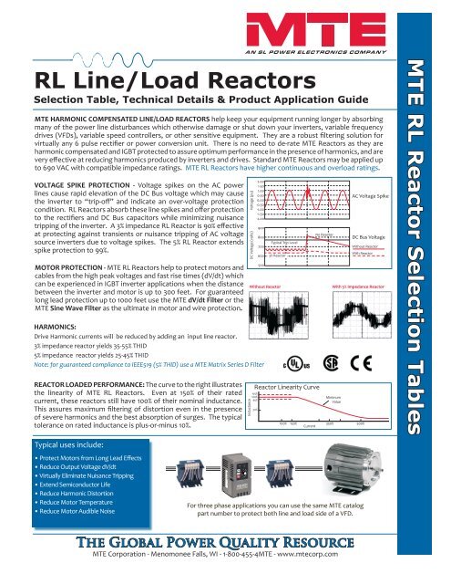
<strong>RL</strong> <strong>Line</strong>/<strong>Load</strong> <strong>Reactors</strong><br />
Selection Table, Technical Details & Product Application Guide<br />
MTE HARMONIC COMPENSATED LINE/LOAD REACTORS help keep your equipment running longer by absorbing<br />
many of the power line disturbances which otherwise damage or shut down your inverters, variable frequency<br />
drives (VFDs), variable speed controllers, or other sensitive equipment. They are a robust filtering solution for<br />
virtually any 6 pulse rectifier or power conversion unit. There is no need to de-rate MTE <strong>Reactors</strong> as they are<br />
harmonic compensated and IGBT protected to assure optimum performance in the presence of harmonics, and are<br />
very effective at reducing harmonics produced by inverters and drives. Standard MTE <strong>Reactors</strong> may be applied up<br />
to 690 VAC with compatible impedance ratings. MTE <strong>RL</strong> <strong>Reactors</strong> have higher continuous and overload ratings.<br />
VOLTAGE SPIKE PROTECTION - Voltage spikes on the AC power<br />
lines cause rapid elevation of the DC Bus voltage which may cause<br />
the inverter to “trip-off” and indicate an over-voltage protection<br />
condition. <strong>RL</strong> <strong>Reactors</strong> absorb these line spikes and offer protection<br />
to the rectifiers and DC Bus capacitors while minimizing nuisance<br />
tripping of the inverter. A 3% impedance <strong>RL</strong> Reactor is 90% effective<br />
at protecting against transients or nuisance tripping of AC voltage<br />
source inverters due to voltage spikes. The 5% <strong>RL</strong> Reactor extends<br />
spike protection to 99%.<br />
MOTOR PROTECTION - MTE <strong>RL</strong> <strong>Reactors</strong> help to protect motors and<br />
cables from the high peak voltages and fast rise times (dV/dt) which<br />
can be experienced in IGBT inverter applications when the distance<br />
between the inverter and motor is up to 300 feet. For guaranteed<br />
long lead protection up to 1000 feet use the MTE dV/dt Filter or the<br />
MTE Sine Wave Filter as the ultimate in motor and wire protection.<br />
HARMONICS:<br />
Drive Harmonic currents will be reduced by adding an input line reactor.<br />
3% impedance reactor yields 35-55% THID<br />
5% impedance reactor yields 25-45% THID<br />
Note: for guaranteed compliance to IEEE519 (5% THID) use a MTE Matrix Series D Filter<br />
REACTOR LOADED PERFORMANCE: The curve to the right illustrates<br />
the linearity of MTE <strong>RL</strong> <strong>Reactors</strong>. Even at 150% of their rated<br />
current, these reactors still have 100% of their nominal inductance.<br />
This assures maximum filtering of distortion even in the presence<br />
of severe harmonics and the best absorption of surges. The typical<br />
tolerance on rated inductance is plus-or-minus 10%.<br />
Typical uses include:<br />
• Protect Motors from Long Lead Effects<br />
• Reduce Output Voltage dV/dt<br />
• Virtually Eliminate Nuisance Tripping<br />
• Extend Semiconductor Life<br />
• Reduce Harmonic Distortion<br />
• Reduce Motor Temperature<br />
• Reduce Motor Audible Noise<br />
For three phase applications you can use the same MTE catalog<br />
part number to protect both line and load side of a VFD.<br />
The Global Power Quality Resource<br />
MTE Corporation - Menomonee Falls, WI - 1-800-455-4MTE - www.mtecorp.com<br />
Voltage (pu)<br />
DC Voltage (volts)<br />
2.00<br />
1.50<br />
1.00<br />
0.50<br />
0.00<br />
-0.50<br />
-1.00<br />
-1.50<br />
-2.00<br />
900<br />
800<br />
700<br />
600<br />
500<br />
Typical Trip Level<br />
3% Reactor<br />
Reactor <strong>Line</strong>arity Curve<br />
No Reactor<br />
AC Voltage Spike<br />
DC Bus Voltage<br />
Without Reactor<br />
With Reactor<br />
Without Reactor With 5% Impedance Reactor<br />
Inductance<br />
105%<br />
100%<br />
95%<br />
50%<br />
Minimum<br />
Value<br />
100% 150% 350% 500%<br />
Current<br />
MTE <strong>RL</strong> Reactor Selection Tables
Selection Table 208-690 VAC Three-Phase and Single-Phase Applications<br />
For detailed product specifications refer to the <strong>RL</strong> User Manual or <strong>RL</strong> Reference Sheet.<br />
This table is suitable for selection of both input & output 3-phase reactors<br />
because their harmonic compensation & conservative design allow them to be<br />
used in either application. Specific current & inductance ratings are indicated<br />
on Pages 4 & 5. Consult factory for any special applications (higher current,<br />
motor rating different than controller rating, etc).<br />
Select <strong>RL</strong> line/load reactors based upon motor horsepower (or kilowatts) and<br />
voltage. Verify that the motor full load ampere name plate rating is within<br />
the RMS current rating of the reactor, & the drive/inverter rating is within the<br />
maximum continuous current rating of the reactor<br />
Agency Approvals:<br />
MTE <strong>RL</strong> <strong>Reactors</strong> are manufactured to the exacting standards of MIL-I-45208, VDE-<br />
0550, & are UL Listed and CSA certified. All UL approvals are for USA & Canada.<br />
•<br />
•<br />
CSA File #LR29753-13, open units up to 2400A<br />
UL-508 File #E180243, open and enclosed up to 2400A<br />
NEMA Cabinets:<br />
<strong>RL</strong> reactors are available as either open type or in a NEMA Type 1 general<br />
purpose enclosure or NEMA type 3R weather. To order a reactor mounted in<br />
a cabinet simply change the second last digit of the part number from “0” to<br />
“1” (NEMA1) or “3” for (NEMA 3R) Cabinets.<br />
Example: <strong>RL</strong>-00802 enclosed becomes <strong>RL</strong>-00812.<br />
Impedance Rating:<br />
3% impedance reactors are typically sufficient<br />
to absorb power line spikes and motor current<br />
surges. They will prevent nuisance tripping of<br />
drives or circuit breakers in most applications.<br />
5% impedance reactors are best for reducing<br />
harmonic currents and frequencies. Use them<br />
when you must reduce VFD drive generated<br />
harmonics, and to reduce motor operating<br />
temperature, or to reduce motor noise.<br />
I x 2pF x L x √3<br />
RMS 50/60Hz <strong>RL</strong>inductance<br />
% =<br />
x 100<br />
impedance<br />
Note: The effective impedance of the reactor<br />
changes with actual RMS current through the<br />
reactor as seen in the above equation.<br />
A 5% impedance reactor becomes 3% if its current<br />
is reduced to 60%.<br />
The Global Power Quality Resource<br />
MTE Corporation - Menomonee Falls, WI - 1-800-455-4MTE - www.mtecorp.com<br />
V L-L
Selection Table 208-690 VAC Three-Phase and Single-Phase Applications ... Continued<br />
Standard Application of <strong>RL</strong> <strong>Line</strong>/<strong>Load</strong> <strong>Reactors</strong>:<br />
On the input of motor VFD controller or six-pulse nonlinear load, <strong>RL</strong> <strong>Reactors</strong> protect sensitive electronic<br />
equipment from electrical noise created by the drive or inverter (notching, pulsed distortion or<br />
harmonics). <strong>RL</strong> <strong>Reactors</strong> protect the controller from surges or spikes on the incoming power lines and<br />
reduce harmonic distortion. They help to reduce VFD produced non-linear current harmonics that may<br />
cause voltage distortion and effect other devices powered from the same AC mains.<br />
Multiple drives or inverters on a common power line require one reactor per controller. Individual reactors<br />
provide filtering between each controller (reducing crosstalk) and also provide optimum surge<br />
protection for each unit. A single reactor serving several controllers does not provide adequate protection,<br />
filtering or harmonic reduction when the system is partially loaded.<br />
Single Phase input configured drives can be protected from spikes and transient voltage by using standard<br />
3-phase <strong>RL</strong> <strong>Line</strong>/<strong>Load</strong> <strong>Reactors</strong> for 1- phase applications by routing each of the two supply conductors<br />
through an outside coil and leaving the center open. Application Note AN0102 details this use.<br />
Note that the single drive input current is √3 (SQRT 3) times the 3-phase motor values. The above table<br />
may be used to select a reactor for 1-phase input applications.<br />
In extended motor lead applications up to 300 feet use <strong>RL</strong> <strong>Reactors</strong> between the inverter & motor to<br />
reduce dV/dT & motor terminal peak voltage. The use of a separate load reactor also protects the controller<br />
from surge current caused by a rapid change in the load, & even from a short circuit at the load.<br />
MTE <strong>Reactors</strong> also reduce operating temperature & audible noise in motor loads. For a guaranteed<br />
long lead solution up to 1000 feet use the MTE Series A dV/dT Filter. More than one motor on a single<br />
drive presents a complex load not suited to reactor protection. Use an MTE Series A Sine Wave Filter<br />
when there is a need to protect more than one motor or for single motor distances to 15,000 feet.<br />
The Global Power Quality Resource<br />
MTE Corporation - Menomonee Falls, WI - 1-800-455-4MTE - www.mtecorp.com
Current Derating Factor<br />
Selection Table <strong>RL</strong> <strong>Line</strong>/<strong>Load</strong> Reactor Technical Data<br />
r<br />
o<br />
t<br />
c<br />
a<br />
F<br />
g<br />
n<br />
i<br />
t<br />
a<br />
r<br />
e<br />
D<br />
t<br />
n<br />
e<br />
r<br />
r<br />
u<br />
C<br />
1.05<br />
1.00<br />
0.95<br />
0.90<br />
0.85<br />
0.80<br />
0.75<br />
0.70<br />
0.65<br />
0.60<br />
1.05<br />
1.00<br />
0.95<br />
0.90<br />
0.85<br />
0.80<br />
0.75<br />
0.70<br />
Reactor Temperature Derating Curve<br />
0 45 5 0 55 6 0 65 7 0 75 8 0 85 9 0<br />
Ambient Temperature, Deg. C<br />
Altitude Derating Curve<br />
0 3300 6600 9900 13200 16500<br />
Altitude (Feet)<br />
Specifications subject to change without notice<br />
MTE <strong>RL</strong> <strong>Reactors</strong> connection types and<br />
terminals vary by model and rating<br />
The Global Power Quality Resource<br />
MTE Corporation - Menomonee Falls, WI - 1-800-455-4MTE - www.mtecorp.com<br />
MTE <strong>RL</strong> <strong>Reactors</strong> can<br />
be supplied in a variey<br />
of standard enclosures<br />
or open frame type to<br />
enable you to mount<br />
them in your sytem in the<br />
most efficient manner<br />
<strong>RL</strong>-10012<br />
<strong>RL</strong>-50003<br />
CAB-8 - 7# 3.2kg<br />
CAB-13V - 18# 8.2kg
Selection Table <strong>RL</strong> <strong>Line</strong>/<strong>Load</strong> Reactor Technical Data ... Continued<br />
CAB-13V<br />
18# 8.2kg<br />
CAB-17V<br />
27# 12.3kg<br />
Note CAB-26D 72” H x 26.5”W x 24.9”D<br />
CAB- 26D weight is 220# 99.8kg<br />
CAB-26C<br />
144# 65.3kg CAB-42C<br />
303# 137.5kg<br />
The Global Power Quality Resource<br />
MTE Corporation - Menomonee Falls, WI - 1-800-455-4MTE - www.mtecorp.com<br />
PRODUCT SELECTION:<br />
See MTE <strong>RL</strong> Selection<br />
Brochure or visit the MTE<br />
website at<br />
www.mtecorp.com and<br />
select the handy<br />
>> Reactor Click Find
Product Specifications - <strong>RL</strong> Three Phase <strong>Reactors</strong><br />
Refer to the <strong>RL</strong> <strong>Line</strong> /<strong>Load</strong> Reactor User Manual for Detailed Specifications<br />
Standard impedance values by calculation: 1.5%, 2, 3%, 4%, 5% available<br />
Impedance basis Reactor rated current, line voltage, frequency and inductance<br />
Service Factor (continuous) Note: Select reactor based on rated current only<br />
<strong>Reactors</strong> rated 1 to 750 Amps 150% of rating<br />
<strong>Reactors</strong> rated above 750 Amps 125% of rated minimum<br />
Overload rating 200% of rated for 30 minutes<br />
300% of rated for 1 minute<br />
Maximum system voltage 600 Volts ( units with terminal blocks)<br />
690 Volts (units with box lugs or tab terminals)<br />
Maximum switching frequency 20 KHz<br />
Insulation system Class N (200°C 392°F )<br />
Temperature rise (open or enclosed reactors) 135°C 275°F (maximum)<br />
Ambient temperature (open or enclosed reactors) 45°C 113°F (Full rated)<br />
Altitude (maximum) 1000 meters<br />
Fundamental frequency (<strong>Line</strong> or <strong>Load</strong>) 50/60 Hz<br />
Approvals: CE, UL-508, CSA C22.2<br />
Inductance curve (typical) 100% at 100% current<br />
100% at 150% current<br />
50% at 350% current (minimum)<br />
Inductance tolerance +/- 10%<br />
Impregnation: High Bond Strength “Solvent-Less” Epoxy, 200° C<br />
UL94HB recognized<br />
Dielectric Strength 3000 volts rms (4243 volts peak)<br />
dV/dT Protection Meets NEMA MG-1, part 31 (same as inverter duty motors)<br />
AGENCY APPROVALS:<br />
UL-508 File E180243 Component Listed (1 amp – 2400 amps)<br />
UL-508 File E180243 UL Listed NEMA 1 units (1 amp – 2400 amps)<br />
Note: Short Circuit rating not required under Exception No.1 of UL508A SB4.2.1 effective 4/25/06<br />
CSA C22.2 File LR29753-13 CSA Certified (1 amp – 2400 amps)<br />
Class N, 200° C File E66214, Type 200-18, UL Recognized Insulation System<br />
CE Marked<br />
MATERIAL:<br />
Core Steel: Electrical grade high frequency silicon steel<br />
Windings: High dielectric withstand solid copper conductor (220° C)<br />
Enclosures: Sheet steel per UL and CSA requirements. Painted ANSI-61 Grey<br />
Brackets: ASTM structural steel or structural aluminum<br />
Sheet Insulation: DuPont Nomex 410 (220° C)<br />
Epoxy: Ripley Resin Type 468-2 (220° C)<br />
CONSTRUCTION:<br />
CORE: Electrical grade silicon steel magnetic laminations.<br />
WINDINGS: 3000 volts rms dielectric strength (coil-to-coil & coil-to-core).<br />
ASSEMBLY: Windings are assembled onto EI laminations, secured in place &<br />
epoxy impregnated for minimum noise & maximum structural rigidity.<br />
COLOR: Royal Blue<br />
TESTING: Inductance, Hi-Pot 3000 Volts rms (5656 volts peak)<br />
World Headquarters<br />
N83 W13330 Leon Road<br />
Menomonee Falls<br />
Wisconsin 53052<br />
Toll Free 1-800-455-4MTE<br />
Phone: (262) 253-8200<br />
Fax: (262) 253-8222<br />
Form 1185-2D-08<br />
For Technical Support: appengrg@mtecorp.com<br />
For Sales Support: sales@mtecorp.com<br />
Visit us on the Web at:<br />
www.mtecorp.com<br />
© 2008 MTE Corporation<br />
All Rights Reserved<br />
The Global Power Quality Resource<br />
®
Matrix ® Harmonic Filters<br />
Series D - Selection Table & Technical Specifications Guide<br />
IEEE-519 - The Series D Matrix® Harmonics Filter uses patented Harmonics Mitigating Reactor (HMR) technology<br />
to limit full load current distortion to less than 5% THID on virtually any kind of six pulse rectifier supply. Six pulse<br />
rectifiers are commonly found in three phase electronic equipment such as adjustable speed motor drives, welders,<br />
battery chargers, servo drives and other electronic equipment. Matrix® Filters enable your system to meet the voltage<br />
and current distortion limits of IEEE-519, EN61000, AS2279 and G5/4.<br />
Reliability - Harmonic currents reduce equipment life, electrical system reliability, system efficiency and equipment<br />
productivity. Matrix® Filters reduce the burden on electrical equipment by reducing TRUE RMS current, peak current and<br />
harmonic frequency distortion. The series impedance included in the Matrix® Filter also absorbs transient over-voltages just like<br />
a line reactor, to prevent over-voltage trips and rectifier damage. Matrix® Filters also reduce the TRUE RMS current that flows<br />
through equipment feeding non-linear loads. This reduces the amount of heat generated by upstream equipment (such<br />
as transformers, disconnects, fuses, circuit breakers and conductors), extending their life expectancy. Increased<br />
system reliability leads to higher productivity for your overall system.<br />
MDP0482D<br />
Performance, Guaranteed! - Matrix® Harmonic Filters can meet or exceed<br />
the harmonic mitigation performance of other common filtration methods. Unlike<br />
alternative solutions, Matrix® Filters come with a performance guarantee. The<br />
Series D Matrix® Filter allows users to achieve superior attenuation of harmonics<br />
when used with 6 pulse drives and will outperform techniques using 12-pulse or<br />
18-pulse rectification methods. The new patented HMR (Harmonic Mitigating<br />
Reactor) optimizes the technology for smaller packaging requiring less floor or<br />
panel space than other filter schemes. On AC variable frequency, variable torque<br />
drive applications (fans & pumps), Matrix filters will meet the guaranteed maximum<br />
levels of THID (total harmonic current<br />
distortion) at full load. Unlike other harmonic<br />
filter technologies, the performance of MTE<br />
Matrix Harmonic Filters is guaranteed!<br />
Installation Options - Matrix Harmonic Filters are available in a variety of enclosure<br />
options. The standard enclosure meets the requirements of both Nema 1 & Nema 2. The Nema<br />
3R enclosure provides weather protection and is available in optional stainless or galvanized<br />
steel construction. Optional Serpent/Rodent screens can be added to block small animals from<br />
entering enclosures.<br />
For maximum flexibility, Matrix filters are also offered as open modular construction for<br />
integration into customer enclosures and panels.<br />
Electrical Options - Various contactor options may be added to provide for filter bypass<br />
and leading KVAR cancellation to enhance compatibility with standby power and support service<br />
requirements.<br />
Typical Uses Include:<br />
• Mission Critical Facilities<br />
• AC Variable Frequency Drives<br />
• DC Adjustable Speed Drives<br />
• Electronic Welders<br />
• Battery Chargers<br />
• Fans and Pumps<br />
• Water Treatment Facilities<br />
• Induction Heating Equipment<br />
• Elevator Drives<br />
• Any 6 Pulse Rectifier Supply<br />
The Matrix Filter is designed to be installed on the line side<br />
of a drive and deliver guaranteed IEEE-519 performance.<br />
The Global Power Quality Resource<br />
MTE Corporation - Menomonee Falls, WI - 1-800-455-4MTE - www.mtecorp.com<br />
MDG0103D<br />
MTE Matrix ® Filter Selection Tables
Selection Table Series D Matrix® Harmonic Filter Technical Data - 208, 240, & 400VAC<br />
Note: replace “_” with P for open panel, “G” General NEMA 1-2 and “W” weather NEMA type 3R in Base part number<br />
Refer to Page 4 for Figures, Cabinet information, and Option details<br />
Matrix® Filters for Variable Torque AC Drives rated 7.5 Hp and above should be selected for a filter output current rating greater than or equal to the motor<br />
current rating. If the motor current rating is not available, use the NEC motor current rating. AC drives rated 2 – 5 Hp should be selected for a filter output<br />
current rating greater than or equal to 105% of the motor current rating. If the motor current rating is not available, select on the basis of 105% of the NEC<br />
motor current rating. For those AC drives rated less than 1.5 Hp selection should be based on an output current rating greater than or equal to 110% of the<br />
motor current rating or 110% of the NEC motor current rating.<br />
For Constant Torque AC and DC Drive applications operating from six pulse rectifier front ends, select a filter current rating according to application<br />
engineering note “Matrix Filter Operation in Constant Torque Applications with Six Pulse Rectifiers” or consult MTE engineering. For phase controlled DC<br />
drive applications, select filter current rating per application note “Matrix Filter with Phase Controlled DC Driver.”<br />
The Capacitor Contactor Option is recommended for generator applications where the kVA rating of the generator is less than 1.20 times the kVA rating of the<br />
Matrix® Filter. Calculate the kVA rating of the Matrix® Filter based on the input voltage rating and the output current rating. Contactor is sized to the filter<br />
capacitor current as listed in the user manual.<br />
Where a single Matrix® Filter is used to feed multiple drives, the output current rating of the filter should be selected to equal the total current rating of the<br />
individual drives when calculated according to the instructions above.<br />
The Global Power Quality Resource<br />
MTE Corporation - Menomonee Falls, WI - 1-800-455-4MTE - www.mtecorp.com
Selection Table Series D Matrix® Harmonic Filter Technical Data - 480 & 600VAC<br />
Note: replace “_” with P for open panel, “G” General NEMA 1-2 and “W” weather NEMA type 3R in Base part number<br />
The Global Power Quality Resource<br />
MTE Corporation - Menomonee Falls, WI - 1-800-455-4MTE - www.mtecorp.com
Enclosure & Electrical Options Series D Matrix® Harmonic Filters<br />
Enclosure Options - Series D Matrix® Harmonic Filters<br />
Option -100 - NEMA 3R enclosure with high endurance white paint: These galvanized enclosures are supplied with continuous welds on the<br />
top cover and weather shields. Exterior hardware is supplied with gaskets.<br />
Option -200 - NEMA 3R STAINLESS STEEL enclosure with high endurance white paint: These enclosures are constructed from 316L stainless<br />
alloy using stainless steel hardware. Gaskets are applied to weather proof exterior components. The exterior surfaces of the enclosure are<br />
finished in high endurance white polyester powder coat.<br />
Option -300 - Standard Grey enclosure with optional Serpent/Rodent screens: Provides intake exhaust air screens with (¼in X ¼in) mesh<br />
openings.<br />
Option -400 - NEMA 3R enclosure with high endurance white paint plus Serpent/Rodent screens: This option incorporates air intake screens<br />
with ¼in X ¼in mesh openings with the white painted NEMA 3R enclosure of Option -100.<br />
Option -500 - NEMA 3R STAINLESS STEEL enclosure with high endurance white paint plus Serpent/Rodent screens: This option incorporates<br />
air intake screens with ¼in X ¼in mesh openings with the white painted NEMA 3R enclosure of Option -200.<br />
Figure 2 -<br />
Open Magnetics<br />
Figure 1 - General Purpose Enclosure<br />
NEMA 1, 2, & 3R<br />
Figure 3 -<br />
Capacitor Assemblies<br />
Electrical Options - Series D Matrix® Harmonic Filters<br />
Option -002 - Capacitor Contactor: This option provides a contactor to disconnect the filter capacitor bank (KVAR current becomes zero)<br />
when the drive is not running. The contactor is supplied with NO/NC auxiliary contacts. The contactor coil and auxiliary contacts are wired to a<br />
customer terminal block. A 120Volt 60Hz power source is required for this option.<br />
Option -012 is a self powered version.<br />
Option -009 - Capacitor Contactor with adjustable pick-up and drop-out: This option provides a contactor to disconnect the filter capacitor<br />
bank based on the motor load current. Two current operated switches provide independent adjustment of the pick-up and drop-out current<br />
levels. The switches are preset at the factory for pick-up at 50% and drop-out at 20% of the filter output current rating. The switches are field<br />
adjustable over a 0% to 100% current range. This option includes a 120VAC control transformer.<br />
Option -010 - Filter Bypass: The filter bypass option is designed to provide filter bypass for drives that have an integrated bypass option as<br />
typically found in HVAC applications. Filter bypass is initiated by a contact closure when the motor is switched to operate directly from the AC<br />
line instead of the drive. A 120VAC control power source is required.<br />
Option -011 is a self powered version.<br />
Option -013 - Filter bypass and capacitor contactor with control transformer: This option combines the filter bypass (Option -010) with a selfpowered<br />
customer controlled capacitor disconnect contactor (Option -012). A jumper selection provides single contact switching for normal<br />
bypass control with capacitor removal.<br />
The Global Power Quality Resource<br />
MTE Corporation - Menomonee Falls, WI - 1-800-455-4MTE - www.mtecorp.com
Distortion<br />
See the Matrix® Filter difference for yourself!<br />
Compare the difference in waveform and harmonic spectrum for real life tests<br />
performed at full load conditions for various harmonic mitigation techniques.<br />
Distortion<br />
Matrix® Filters attenuate harmonics better<br />
than these alternative filtering techniques.<br />
Data based on actual tests at full load power.<br />
5th Harmonic Trap<br />
w/5% <strong>Line</strong> Reactor<br />
Harmonic Order<br />
Part Number Code: MD X _ _ _ _ X _ _ _<br />
Product Code Matrix Series D<br />
Type<br />
P Panel Mnt G General Purpose NEMA2 W Weather NEMA3R<br />
Current Rating<br />
0006 6 amps 0786 786 amps<br />
Voltage Frequency Code<br />
C 380VAC - 415VAC 50Hz D 480VAC 60Hz<br />
Enclosure Options<br />
Contactor Options<br />
MTE Matrix® Filter<br />
Harmonic<br />
12 Pulse<br />
The Global Power Quality Resource<br />
MTE Corporation - Menomonee Falls, WI - 1-800-455-4MTE - www.mtecorp.com<br />
Distortion<br />
Distortion<br />
Harmonic<br />
18 Pulse<br />
Harmonic
Product Specifications - Matrix® Harmonic Filters<br />
Refer to the MTE SERIES D MATRIX® HARMONIC FILTER User Manual for Detailed Specifications<br />
Matrix Filters are designed to operate and will achieve guaranteed performance under the follow conditions:<br />
<strong>Load</strong>: 6 pulse rectifier, operating in variable torque mode and chosen from the<br />
standard selection table. For constant torque application select filter rating<br />
based on appropriate application note: AN-0106<br />
Input voltage: Nominal voltage VAC +/- 10%, 3 Phase<br />
Frequency: Nominal Frequency + .75 Hz<br />
Input voltage line unbalance: 1% maximum<br />
Maximum source impedance: 6.00%<br />
Minimum source impedance: 1.5%<br />
Service Factor: 1.00<br />
Ambient Temperature (Operating)<br />
Enclosed Filters: -40 to +40 degrees C<br />
Open Panel Filters: -40 to +50 degrees C<br />
Storage Temperature: -40 to +90 degrees C<br />
Altitude: 0 to 3300 Feet above sea level<br />
without derating<br />
Relative Humidity: 0 to 95% non-condensing<br />
Agency Approvals<br />
UL and cUL listed : UL508 and CSA-C22.2 No 14-95<br />
File E180243 (3HP to 1000HP,<br />
120VAC to 600VAC, 50Hz, 50/60Hz,<br />
& 60Hz Three Phase)<br />
Performance<br />
Total Harmonic Current Distortion: 5% MAX at FULL LOAD<br />
Performance Guarantee<br />
Select & install the appropriate Matrix Harmonic Filter in a variable torque AC variable frequency drive application, within our published system limits & we<br />
guarantee that the input current distortion will be less than or equal to 5% THID for MD Series filters at full load. If a properly sized & installed filter fails to<br />
meet its specified THID level, MTE will provide the necessary modifications or replacement filter at no charge. TDD will typically be even lower than THID.<br />
Matrix filters can also provide similar performance in other drive applications such as constant torque, DC drives & other phase controlled rectifiers, but<br />
actual THID levels can vary by load and/or speed & therefore cannot be guaranteed. Consult factory for assistance when applying Matrix filters on these<br />
types of equipment<br />
MINIMUM SYSTEM REQUIREMENTS:<br />
The guaranteed performance levels of this filter will be achieved when the following system conditions are met:<br />
Source impedance: 1.5% minimum to 6.0% max<br />
Frequency: 60Hz ± 0.75Hz<br />
System Voltage: Nominal System Voltage (line to line) ±10%<br />
Balanced <strong>Line</strong> Voltage: within 1%,<br />
Background Voltage Distortion: 0% THVD.<br />
NOTE: The presence of background voltage distortion will cause motors & other linear loads to draw harmonic currents. Additional harmonic currents may flow<br />
into the Matrix filter if there is harmonic voltage distortion already on the system.<br />
World Headquarters<br />
N83 W13330 Leon Road<br />
Menomonee Falls<br />
Wisconsin 53052<br />
Toll Free 1-800-455-4MTE<br />
Phone: (262) 253-8200<br />
Fax: (262) 253-8222<br />
Form 1217B-1-08<br />
For Technical Support: appengrg@mtecorp.com<br />
For Sales Support: sales@mtecorp.com<br />
Visit us on the Web at:<br />
www.mtecorp.com<br />
Matrix Series D Filter<br />
Typical Harmonic Spectrum For 100% <strong>Load</strong><br />
© 2008 MTE Corporation<br />
All Rights Reserved<br />
The Global Power Quality Resource<br />
Harmonic<br />
Current %<br />
4<br />
3<br />
2<br />
1<br />
0<br />
5 7 11 13 17 19 23 25<br />
Harmonic<br />
®
Performance of Harmonic Mitigation Alternatives<br />
MTE Corporation<br />
Abstract: Users of variable frequency drives often have strict demands placed on them<br />
to mitigate harmonic distortion caused by non-linear loads. Many choices are available<br />
to them including line reactors, harmonic traps, 12-pulse rectifiers, 18-pulse rectifiers,<br />
and low pass filters. Some of these solutions offer guaranteed results and have no<br />
adverse effect on the power system, while the performance of others is largely<br />
dependent on system conditions. Certain techniques require extensive system analysis<br />
to prevent resonance problems and capacitor failures, while others can be applied with<br />
virtually no analysis whatsoever. In some cases harmonic mitigation technique<br />
decisions were based on a technical misunderstanding, lack of information, theoretical<br />
data or on invalid assumptions.<br />
This paper explains the theory of operation of various passive harmonic mitigation<br />
techniques and demonstrates their typical real life performance. It takes the guesswork<br />
out of harmonic filtering by demonstrating the typical performance of various harmonic<br />
mitigation techniques and offering a quantitative analysis of alternatives for real life VFD<br />
operating conditions.<br />
1 SOURCE REACTANCE<br />
The magnitude of harmonic currents in an individual non-linear load depends greatly on the total<br />
effective input reactance, which is comprised of the source reactance plus added line reactance.<br />
Given a six pulse rectifier with dc bus capacitor, one can predict the resultant input current<br />
harmonic spectrum based on the input reactance. The lower the source reactance, (the more stiff<br />
the power source), the higher the harmonic content will be.<br />
1.1 Typical Harmonic Performance<br />
The typical harmonic spectrum data for a six-pulse rectifier load fed by a stiff power source<br />
(0.25% and 0.5% impedance) is as follows:<br />
0.25% 0.50%<br />
h reactance reactance<br />
5 th 102% 78%<br />
7 th 92% 58%<br />
11 th 26% 18%<br />
13 th 14% 10%<br />
17 th 10% 7%<br />
19 th 8.5% 6%<br />
23 rd 7% 5%<br />
25 th 3% 2.3%<br />
THID 141% 100% (THID = total harmonic current distortion)
Since power distribution transformers frequently have impedance ratings between 1.5% and<br />
5.75%, one would expect that source impedance is often relatively high and that harmonics<br />
should therefore be quite low. However, transformer impedance ratings are based on<br />
transformer rated KVA, so when the transformer is partially loaded, the effective impedance of<br />
the transformer, relative to the actual load, is proportionately lower, [ie: 1.5% impedance at<br />
30% load = 0.5% effective impedance].<br />
2 LINE REACTORS<br />
The use of AC line reactors is a common and economical means of increasing the source<br />
impedance relative to an individual load. <strong>Line</strong> reactors are connected in series with the six pulse<br />
rectifier diodes at the input to the VFD, as shown in Fig 1.<br />
Fig 1.<br />
AC <strong>Line</strong><br />
Reactor<br />
2.1 Typical Harmonic Performance of <strong>Reactors</strong><br />
The typical harmonic spectrum data for a six pulse VFD load fed by a power supply with an<br />
effective source reactance of 3%, 5% and 8% looks as follows:<br />
3 % 5% 8% impedance<br />
h reactance reactance 3% dc choke & 5% ac reactor<br />
5 th 39% 32% 27%<br />
7 th 17% 12% 9%<br />
11 th 7% 5.8% 4.5%<br />
13 th 5% 3.9% 3.2%<br />
17 th 3% 2.2% 1.8%<br />
19 th 2.2% 1.7% 1.4%<br />
23 rd 1.5% 1% 0.8%<br />
25 th 1% 0.9% 0.75%<br />
THID 44% 35% 29%<br />
These data represent the harmonics measured at the input to the six pulse rectifier and will<br />
reduce to lower percentages when measured further upstream, provided there are other linear<br />
loads operating on the system. If 20% of the system load is comprised of VFDs with 5% input<br />
impedance, and 80% has linear loads, the harmonic current distortion at the VFD input will be<br />
35% THID, but only 7% at the supply transformer secondary. Typically costing less than 3% of<br />
the motor drive system, line reactors are the most economical means of reducing harmonics.<br />
Practical ratings can achieve 29% to 44% THID at the input to the six pulse rectifier (usually<br />
lower THID at the transformer secondary), at full load operation. Their typical watts losses are<br />
less than 1% of the load.
Fig. 2 illustrates the input current waveform of a six pulse rectifier supplied by a power source of<br />
(a) 0.5% effective impedance and (b) 3% effective impedance.<br />
Fig. 2(a) Input Current waveform of Fig. 2(b) Input current of 6-pulse<br />
6-pulse rectifier w/0.5% impedance rectifier w/ 3% impedance<br />
Fig. 3 illustrates the typical harmonic spectrum for a six-pulse rectifier with 0.5%, 5% or 8%<br />
effective source impedance, (8% = 5% line reactor + 3% DC bus choke).<br />
% THID<br />
60%<br />
40%<br />
20%<br />
harmonic<br />
2.2 Reactor Performance at Light <strong>Load</strong><br />
The harmonic mitigation performance of reactors varies with load because their effective<br />
impedance reduces proportionately as the current through them is decreased. At full load, a 5%<br />
effective impedance reactor achieves harmonic distortion of 35% THID, however, at 60% load<br />
it’s effective impedance is only 3% {0.6 x 5% = 3%}, and harmonics will be 44% THID.<br />
Although THID increased as a percentage, the total rms magnitude of harmonic current actually<br />
decreased by nearly 25% {1 – ((.6 x 44%) / 35%) = 24.5%}. Since voltage distortion at the<br />
transformer secondary is dependent upon the magnitude and frequency of current harmonics that<br />
cause harmonic voltage drops across the transformer‘s internal reactance, the voltage distortion<br />
(THVD), at the transformer secondary, actually decreases as this load is reduced.<br />
3 TUNED HARMONIC TRAP FILTERS<br />
3.1 Harmonic Trap Performance<br />
0.5% impedance<br />
5% Impedance Reactor<br />
5% Impedance Reactor & 3% DC Choke<br />
5 th 7 th 11 th 13 th 17 th 19 th<br />
Tuned harmonic filters (traps) involve the series connection of an inductance and capacitance to<br />
form a low impedance path for a specific (tuned) harmonic frequency. The filter is connected in<br />
parallel (shunt) with the power system to divert the tuned frequency currents away from the<br />
power source.
Source Impedance<br />
Input Current<br />
Fig. 4 (with 0.25% source impedance)<br />
Unlike line reactors, harmonic traps do not attenuate all harmonic frequencies. Most often they<br />
are tuned for 5 th harmonic mitigation. If applied to a low impedance power source, as<br />
demonstrated in Fig. 4, the harmonic mitigation performance of this filter is quite limited and the<br />
benefit of this filter may be unrecognizable. To improve the performance of a trap filter, a 5%<br />
impedance line reactor may be connected in series with the input to the filter, as shown in Fig. 5.<br />
Input current<br />
5% reactor<br />
6pulse<br />
VFD<br />
Harmonic Trap<br />
VFD<br />
Basic<br />
Harmonic Trap<br />
Fig. 5 (with 0.25% source impedance)<br />
THID = 24.5%<br />
If the VFD has internal line reactance, then harmonic trap performance may improve slightly.<br />
The typical residual THID for a six pulse rectifier with a tuned 5 th harmonic trap is between 20%<br />
to 30% at full load, provided there is significant source impedance. The watts loss of this type<br />
of filter can be 2-3% of the load and it can cost ten times the price of a line reactor. Tuned<br />
harmonic traps will alter the natural resonant frequency of the power system and may cause<br />
system resonance, increasing specific harmonic levels. They may attract harmonics from other<br />
non-linear loads sharing the same power source and must be increased in capacity to<br />
accommodate the addition of new loads. For best results, a power system study should be<br />
performed to determine the magnitude of harmonics to be filtered (from all loads), the power<br />
system resonant frequency and the impact of future addition of loads.<br />
3.2 Harmonic Traps at Light <strong>Load</strong> Conditions<br />
435.7m 450.0m 462.5m 475.0m<br />
499.5m<br />
Harmonic traps achieve their best attenuation of harmonics at full load conditions. At light load,<br />
the resultant THID can increase significantly and may be no better than the performance<br />
normally achieved with a line reactor. Fig. 6 demonstrates the input current waveform of a six<br />
pulse rectifier with a tuned 5 th harmonic trap, operating at 50% load, when the line voltages<br />
were 3% unbalanced. Notice the similarity to a non-linear single phase load.<br />
50.00<br />
0<br />
50.00<br />
25.00<br />
0<br />
-25.00<br />
Input Current<br />
-50.00<br />
379.5m 425.0m 450.0m<br />
492.5m<br />
L5.I ...<br />
L5.I = f(...
Fig. 6 Input current waveform for a<br />
Six-pulse rectifier with 5 th harmonic<br />
tuned harmonic filter, measured at 50% load,<br />
and with 3% line voltage unbalance and<br />
0.25% source impedance.<br />
Harmonic current distortion = 139% THID<br />
4 12-PULSE RECTIFICATION<br />
4.1 Theory of performance<br />
Fig. 6<br />
Twelve pulse rectifier configurations have been used for applications demanding lower harmonic<br />
levels than can be achieved using either traps or reactors. The theoretical benefits of 12-pulse<br />
rectification include cancellation of 5 th , 7 th , 17 th , 19 th , etc harmonics. However, real life<br />
harmonic mitigation resulting from the use of twelve pulse rectifiers can be quite different than<br />
one’s theoretical expectations. The most common method of twelve pulse rectification involves<br />
the parallel connection of two bridge rectifiers, each fed by a 30 degrees phase shifted<br />
transformer winding. Often the transformer has a single primary winding and dual secondary<br />
windings. One secondary winding is a delta and the other is connected in wye configuration to<br />
achieve 30 degrees of phase shift between secondary voltages.<br />
“A major design goal in multipulse operation is to get the converters, or converter<br />
semiconductor devices, to share current equally. If this is achieved, then maximum power and<br />
minimum harmonic currents can be obtained.” (1) In order to achieve cancellation of harmonics,<br />
the two individual bridge rectifiers must share current equally. This can only be achieved if the<br />
output voltage of both transformer secondary windings are exactly equal. “Because of<br />
differences in the transformer secondary impedances and open circuit output voltages, this can<br />
be practically accomplished for a given load (typically rated load) but not over a range in<br />
loads.” (2) Typical losses of a twelve pulse transformer are 3% to 5% of the transformer KVA<br />
rating.<br />
4.2 Twelve Pulse Performance with Balanced <strong>Line</strong> Voltages<br />
Fig. 7 illustrates actual measurements of input current harmonic distortion for a twelve pulse<br />
rectifier supplied from a balanced three phase voltage source while operating at full load<br />
conditions. For test purposes, the transformer had a delta primary with delta and wye secondary<br />
windings (each rated at one-half line voltage). To obtain “best case” results, the bridge rectifiers<br />
were series connected so equal DC current flowed in each converter. The data shows that when<br />
the current through both sets of rectifiers is equal, harmonics can be as low as 10% to 12%<br />
THID at full load. Current sharing reactors will help parallel connected bridge rectifiers to share<br />
current equally. While current sharing reactors are highly recommended for twelve pulse<br />
configurations, they are usually omitted in the interest of minimizing cost. Even with balanced<br />
current however, harmonic distortion can increase appreciably at light load conditions.<br />
0<br />
441.3m 462.5m<br />
500.0m<br />
L5.I...
% THID<br />
Fig. 7 Harmonic spectrum for 12-pulse rectifier, measured while operating at full load,<br />
when line voltages were balanced.<br />
4.3 Twelve-Pulse Performance when <strong>Line</strong> Voltages are Not Balanced<br />
Practical aspects of multipulse transformer winding configurations and circuit parameters make<br />
it unlikely that perfect balance can be achieved between all six secondary voltages, especially<br />
when the load is varied from full load to no load conditions. Additionally, facility power system<br />
voltage unbalance is common (according to ANSI C84.1, 34% of facilities surveyed in the USA<br />
experienced between 1% and 3% voltage unbalance at the service entrance point and even<br />
greater unbalance in the facility and closer to the loads). It is interesting to note that occasionally<br />
12-pulse drives are sold without the transformer, shifting responsibility for the transformer<br />
specification and system performance from the supplier to the user or installer. Fig. 8<br />
demonstrates the impact of both line voltage unbalance and light loading conditions on the<br />
harmonic mitigation performance of twelve pulse rectifiers. Even with perfectly balanced line<br />
voltages, the resultant %THID increases as the load is reduced (ie: 23% THID at 20% load).<br />
Total Input Current Distortion<br />
80%<br />
70%<br />
60%<br />
50%<br />
40%<br />
30%<br />
20%<br />
10%<br />
2%<br />
1% 3% 4%<br />
0%<br />
10%<br />
9%<br />
8%<br />
7%<br />
6%<br />
5%<br />
4%<br />
3%<br />
2%<br />
1%<br />
0%<br />
Fig. 8<br />
4%<br />
3%<br />
2%<br />
1%<br />
0%<br />
2- pulse<br />
R tifi<br />
Harmonic Measurements at FULL LOAD<br />
1 5 7 11 13 17 19 21 23 25 29 31 35<br />
Harmonic<br />
Various <strong>Line</strong> Im balances<br />
30HP, 480V, 12-pulse, NO Bus Inductors<br />
Total Input Current Harmonic Distortion -- Varying with <strong>Load</strong><br />
4%<br />
3%<br />
2%<br />
1%<br />
0%<br />
4%<br />
3%<br />
2%<br />
1%<br />
0%<br />
0%<br />
0% 20% 40% 60% 80% 100% 120%<br />
Percent <strong>Load</strong><br />
Measured<br />
current<br />
distortion is<br />
10.5% THID<br />
2%<br />
4%<br />
3%<br />
1%<br />
0%
5 EIGHTEEN PULSE RECTIFIERS<br />
5.1 18-Pulse Rectifier Theory of Operation<br />
Eighteen pulse configurations use a transformer with three sets of three phase outputs that are<br />
phase shifted by 20 degrees each, to supply three sets of full wave bridge rectifiers.<br />
Theoretically, this configuration cancels the 5 th , 7 th , 11 th , 13 th , 23 rd , 25 th , 29 th , 31 st , etc<br />
harmonics. One might imagine that it may be quite optimistic to expect the nine supply voltages,<br />
feeding three bridge rectifiers, to be exactly equal at all operating conditions. Maintaining equal<br />
DC current through three bridges seems more difficult than with twelve pulse systems simply<br />
because the number of variables increases by fifty percent. As with 12-pulse systems, the 18pulse<br />
rectifier’s ability to reduce harmonic currents is best when operating at full load conditions<br />
and when all of the nine voltages are equal.<br />
5.2 18-Pulse Rectifier Performance at Full <strong>Load</strong> with Balanced <strong>Line</strong> Voltages<br />
In a laboratory exercise it is possible to control the three line voltages that supply the 18-pulse<br />
transformer primary winding, however in real life applications this may be quite difficult to<br />
achieve. Even when the primary voltages are balanced, maximum attenuation of harmonics<br />
with 18-pulse rectifiers, requires that all nine secondary voltages be balanced. This allows DC<br />
current to be shared equally by each of the three bridge rectifiers, provided the semiconductor<br />
and circuit resistances are identical for all phases. Due to the large number of variables, the<br />
likelihood of achieving theoretical harmonic performance is rather poor. Fig. 9 demonstrates the<br />
harmonic current spectrum measurement for an 18-pulse rectifier, operating at full load, with the<br />
three primary voltages balanced. To demonstrate the best case scenario, the three bridge<br />
rectifiers were connected in series to assure equal sharing of DC current.<br />
10%<br />
9%<br />
8%<br />
7%<br />
6%<br />
5%<br />
4%<br />
3%<br />
2%<br />
1%<br />
0%<br />
Harmonic Measurements at FULL LOAD<br />
Measured<br />
current<br />
distortion is<br />
7.5% THID<br />
1 5 7 11 13 17 19 21 23 25 29 31 35<br />
Harmonic<br />
Fig. 9 Harmonic spectrum for 18-pulse rectifier, measured while operating at full load,<br />
when line voltages were balanced.
5.3 Effects of Unbalanced <strong>Line</strong> Voltage on 18-pulse Rectifiers<br />
Similar to twelve pulse systems, 18-pulse rectifiers experience diminishing performance when<br />
line voltages are not balanced, and when operating at less than full load. 18-pulse drives may<br />
offer guaranteed harmonic distortion levels, but typically only at full load and full speed<br />
conditions, with voltages that are balanced within one percent. Fig. 10 illustrates the effect of<br />
unbalanced line voltages on 18-pulse drives operating between full load and no load conditions.<br />
Total Harmonic Current Distortion THID, %<br />
Fig. 10<br />
100<br />
90<br />
80<br />
70<br />
60<br />
50<br />
40<br />
30<br />
20<br />
10<br />
0<br />
18 Pulse Drive- with <strong>Line</strong> Voltages Unbalanced by 1% to 3%<br />
18-Pulse Drive<br />
3% <strong>Line</strong> Unbalance<br />
2% <strong>Line</strong> Unbalance<br />
1% <strong>Line</strong> Unbalance<br />
0 10 20 30 40 50 60 70 80 90 100 110<br />
<strong>Load</strong>, %<br />
Notice that as the load is decreased the magnitude of percent harmonic distortion increases<br />
significantly. While %THID at full load may be fairly low, at 40% load, harmonic current<br />
distortion was measured to be over 20%THID, when the line voltages were only one percent<br />
unbalanced. When the line voltage unbalance was three percent, the harmonic current distortion<br />
increased to over 40%THID. To enhance the performance of 18-pulse drives, line reactors may<br />
be added in series with the individual bridge rectifiers. This is demonstrated in Fig. 11.
Total Harmonic Current Distortion, THID,<br />
%<br />
Fig. 11<br />
100<br />
90<br />
80<br />
70<br />
60<br />
50<br />
40<br />
30<br />
20<br />
10<br />
0<br />
6 Matrix Harmonic Filters<br />
6.1 Theory of Operation<br />
18-Pulse Drives<br />
3% <strong>Line</strong> Voltage Unbalance<br />
18-Pulse Drive<br />
18-Pulse Drive with 5% <strong>Line</strong> <strong>Reactors</strong><br />
for Each Rectifier<br />
0 10 20 30 40 50 60 70 80 90 100 110<br />
<strong>Load</strong>, %<br />
Matrix Harmonic Filters are low pass, passive harmonic filters. They connect in series at the<br />
input to any six pulse drive. Being a low pass filter, the Matrix Filter attenuates each harmonic<br />
frequency, resulting in the lowest harmonic distortion levels of any passive filter. Their<br />
performance, in real life operating conditions such as unbalanced line voltages and from no load<br />
to full load is superior to all of the passive techniques discussed previously in this paper. Typical<br />
losses associated with Matrix Harmonic Filters are less than one percent of the load power rating.<br />
These low pass filters do not cause power system resonance problems and do not attract<br />
harmonics from other non-linear loads sharing the same power source. Harmonic distortion<br />
performance guarantees are offered for variable frequency, variable torque applications.
6.2 Matrix Filter Performance<br />
Matrix filters convert any six pulse drive to<br />
harmonic mitigation performance that is<br />
better than 18-pulse rectification. The<br />
typical input current waveform and<br />
harmonic spectrum are demonstrated in Fig.<br />
12(a) and Fig. 12(b).<br />
%<br />
THID<br />
10%<br />
9%<br />
8%<br />
7%<br />
6%<br />
5%<br />
4%<br />
3%<br />
2%<br />
1%<br />
0%<br />
Fig. 12(a) Matrix Filter Input Current<br />
Fig. 12(b) Actual Matrix Filter Harmonic Measurements at FULL LOAD<br />
1 5 7 11 13 17 19 23 25 29 31 35<br />
Harmonic<br />
Fig. 12(b) Input current spectrum for 6-pulse drive with Matrix Filter.<br />
6.3 Matrix Filter Performance with Unbalanced <strong>Line</strong> Voltage<br />
Measured<br />
current<br />
distortion is<br />
4.8% THID<br />
Due to their internal series reactance, component tolerances and circuit configuration, Matrix<br />
Filters are only mildly affected by unbalanced line voltage conditions. It is also apparent in Fig.<br />
13, that Matrix Filter performance is quite consistent from no load to full load conditions.<br />
This is demonstrated by the comparison of Matrix Filters to the 18-pulse drives previously<br />
discussed. The combination of six pulse VFD and Matrix Filter attenuated harmonics better than<br />
the eighteen pulse drive, when tested with various percentages of line voltage unbalance, and<br />
when operating at load conditions ranging from 0% to 100% load. By comparison of Fig. 11 and<br />
Fig. 13, the six pulse drive with Matrix filter also reduced harmonics to lower levels than the<br />
enhanced 18-pulse drive, which used additional line reactors.
Total Harmonic Current Distortion THID, %<br />
100<br />
90<br />
80<br />
70<br />
60<br />
50<br />
40<br />
30<br />
20<br />
10<br />
0<br />
8% Matrix Filter<br />
3% Unbalance<br />
2% Unbalance<br />
1% Unbalance<br />
18 Pulse Drive vs. 6-pulse VFD with Matrix Filter<br />
3% <strong>Line</strong> Unbalance<br />
0 10 20 30 40 50 60 70 80 90 100 110<br />
7 TRIPLEN HARMONICS<br />
<strong>Load</strong>, %<br />
18-Pulse Drive<br />
2% <strong>Line</strong> Unbalance<br />
1% <strong>Line</strong> Unbalance<br />
Triplen harmonics are typically not present in a balanced three phase system. They occur<br />
however when the line voltages are not balanced, or when the line voltage is distorted by nonlinear<br />
single phase loads. The presence of triplen harmonics increases the resultant THID level<br />
for virtually any passive harmonic mitigation equipment. Some mitigation techniques, such as<br />
multi-pulse drives, are highly sensitive to voltage unbalance as demonstrated in Fig. 8, Fig. 11<br />
and Fig. 13. Tuned 5 th harmonic traps also experience significantly elevated %THID levels<br />
when line voltages are not balanced, as demonstrated in Fig. 6. Matrix Filters achieve better<br />
attenuation of harmonics under real life operating conditions because they are only minimally<br />
influenced by unbalanced line voltages, as demonstrated by Fig.13. Additionally, they provide<br />
superior harmonic mitigation performance at operating conditions that range from no load to full<br />
load.<br />
8 CONCLUSION<br />
Fig. 13<br />
Electrical system reliability and normal life expectancy of electrical equipment rely<br />
heavily upon a clean and reliable power supply. Those wishing to maximize productivity<br />
through utilization of clean power technologies have several harmonic mitigation<br />
techniques available. Each technique has a different cost, power loss, and harmonic<br />
distortion reduction benefit. Some solutions, such as Matrix Harmonic Filters provide
harmonic performance guarantees, while others may require extensive analysis. This<br />
paper demonstrates that theoretical performance is not necessarily a valid estimate of<br />
the actual expected performance of most mitigation techniques when operating under<br />
real life conditions. The performance level of most techniques diminishes in the real<br />
world due to the presence of unbalanced line voltages and operation at less than 100%<br />
loading conditions.
July 2002<br />
Solving DC Drive Harmonics with Matrix<br />
Harmonic Filters<br />
Matrix Filters may be used for phase controlled DC drive applications to improve power<br />
factor and reduce line harmonics. Application to DC drives is similar to AC drives with a few<br />
important differences in filter performance and the selection of the appropriate filter rating.<br />
The following paragraphs cover these differences.<br />
Matrix Filter Selection<br />
Selection of the proper Matrix Filter rating for a DC drive is based on the horsepower and<br />
voltage rating of the drive. Applications for DC motors rated at 500 volts or higher may use a<br />
480 VAC filter rated at the same horsepower as the DC drive provided the motor efficiency is<br />
a minimum of 85%. DC motors with lower efficiencies will typically draw higher ac input<br />
current and therefore a Matrix Filter rated for higher horsepower may be required. The<br />
following equation should be used to select the correct filter rating:<br />
Matrix Filter HP = DC Drive HP x 85%<br />
DC motor efficiency<br />
If the calculated filter horsepower falls between two standard horsepower ratings, the next<br />
larger filter rating should be selected. This will insure that the drive may be used at full rated<br />
horsepower without overheating the Matrix Filter components. Do not use this equation to<br />
downsize the Matrix Filter when motor efficiencies are greater than 85%. The same type of<br />
scaling is necessary for motors with armature voltage ratings less than 500 volts. To select a<br />
Matrix Filter for a DC drive, when the motor armature voltage is less than 500 volts use the<br />
following equation.<br />
Matrix Filter HP = DC Drive HP x 500Volts<br />
Rated Armature Voltage<br />
APPLICATION NOTE<br />
If the calculated filter horsepower falls between two standard horsepower ratings, the next<br />
larger filter rating should be selected.<br />
Page 1 of 4<br />
Doc. #AN0105
Matrix Filter Performance<br />
Matrix Filters are suitable for use with DC drives and other phase controlled rectifier<br />
applications, but harmonic performance will vary based upon controller output voltage<br />
(speed) and output current (load). While it is not possible to specify guaranteed levels of<br />
harmonic distortion for Matrix Filters used with phase controlled SCR applications, Matrix<br />
filters are extremely effective at solving harmonics problems associated with DC Drives and<br />
other six-pulse phase controlled rectifiers.<br />
The performance of the Matrix Filter with a DC drive differs from that with an AC drive due<br />
to two main factors: (1) the harmonic content of the DC drive line current waveform tends to<br />
have higher amplitude harmonics at the 11 th and higher, and (2) the line current of the DC<br />
drive is mainly dependent on motor torque, not motor power. The effect of these differences is<br />
an increase of about 10% - 50% in THID under full torque conditions and a noticeable rise in<br />
THID during lightly loaded low speed operation. Although for this reason, the Matrix Filter<br />
performance guarantee does not apply to DC drive applications, Matrix Filters are very<br />
effective at solving DC drive harmonic problems.<br />
This rise in percent distortion is not due to an increase in absolute harmonic current, but<br />
results from the cancellation of the lagging fundamental drive current with the leading filter<br />
capacitor current. See figures 1, 2, and 3 for nominal THID curves of a 500-volt DC motor at<br />
100%, 50%, and 10% speed. In this example the drive is operating from a nominal 480 VAC<br />
line.<br />
Percent FIG. 1<br />
12<br />
10<br />
8<br />
6<br />
4<br />
2<br />
0<br />
12% Filter w/DC Drive @ 500V Armature<br />
Nominal THID<br />
0% 50% 100% 150% 200%<br />
Normalized Output C urrent<br />
Page 2 of 4
Percent<br />
FIG. 2<br />
20<br />
15<br />
10<br />
5<br />
0<br />
60<br />
50<br />
40<br />
30<br />
20<br />
Percent FIG. 3<br />
10<br />
0<br />
12% Filter w/DC Drive @ 250V Armature<br />
Nominal THID<br />
0% 50% 100% 150% 200%<br />
Normalized Output Current<br />
12% Filter w/DC Drive @ 50V Armature<br />
Nominal THID<br />
0% 50% 100% 150% 200%<br />
Normalized Output Current<br />
Page 3 of 4
Available Motor Overload Current<br />
The limitation on available motor overload current with a Matrix Filter on a DC drive depends<br />
on many of the same factors as an AC application. Rated motor voltage, operating speed, line<br />
impedance, and filter type are all important parameters. The worst case conditions are full<br />
armature voltage, low line voltage, high line impedance, and an 8% versus a 12% filter.<br />
Figures 4 and 5 show the worst case available currents with 6% line impedance as armature<br />
percent resistance varies. Figures 6 and 7 are the same curves with 3% line impedance.<br />
250%<br />
240%<br />
230%<br />
220%<br />
210%<br />
200%<br />
190%<br />
180%<br />
170%<br />
160%<br />
150%<br />
290%<br />
270%<br />
250%<br />
230%<br />
210%<br />
190%<br />
170%<br />
Available Overload vs. Armature Resistance<br />
12% Matrix Filter, 6% <strong>Line</strong>, 500V Motor<br />
0% 4% 8% 12% 16%<br />
480V <strong>Line</strong> 460V <strong>Line</strong><br />
Figure 4 Figure 5<br />
Available Overload vs. Armature Resistance<br />
12% Matrix Filter, 3% <strong>Line</strong>, 500V Motor<br />
150%<br />
0% 4% 8% 12% 16%<br />
480V <strong>Line</strong> 460V <strong>Line</strong><br />
210%<br />
200%<br />
190%<br />
180%<br />
170%<br />
160%<br />
150%<br />
Figure 6 Figure 7<br />
Page 4 of 4<br />
Available Overload vs. Armature Resistance<br />
8% Matrix Filter, 6% <strong>Line</strong>, 500V Motor<br />
0% 4% 8% 12% 16%<br />
250%<br />
240%<br />
230%<br />
220%<br />
210%<br />
200%<br />
190%<br />
180%<br />
170%<br />
160%<br />
480V <strong>Line</strong> 460V <strong>Line</strong><br />
Available Overload vs. Armature Resistance<br />
8% Matrix Filter, 3% <strong>Line</strong>, 500V Motor<br />
150%<br />
0% 4% 8% 12% 16%<br />
480V <strong>Line</strong> 460V <strong>Line</strong>
A P P L I C A T I O N N O T E<br />
Document #: AN0102<br />
May, 2000<br />
Page 1 of 2<br />
How to use a 3-phase line reactor for a single-phase application!<br />
The illustration below demonstrates how a 3-phase line reactor can be used for a<br />
single-phase application. Using the mathematical method below you can calculate the<br />
inductance to determine what type of reactor is needed.<br />
<strong>Reactors</strong> <strong>Reactors</strong> for for Single Single Phase Phase Applications<br />
Applications<br />
MTE three-phase <strong>Line</strong> / <strong>Load</strong> <strong>Reactors</strong> can be used for single-phase applications by routing<br />
each of the two supply conductors through an outside coil, and leaving the center coil<br />
disconnected. For the drive input application shown in (Figure 1.), the incoming supply lines<br />
connect to terminals A1, C1, and outgoing lines from A2, C2. The "B" terminals for the<br />
center coil are not connected. The sum of the inductance of the two coils is the total<br />
inductance applied to the circuit.<br />
(Figure 1.)<br />
As an example, consider a single-phase application of 2HP supplied by 240 Vac. The reactor<br />
must carry 12A (fundamental current) according to the NEC table for single-phase motor<br />
current. A 5% impedance is desired. For a 60Hz supply, the formula to calculate required<br />
inductance is: L = (ZV) / (377I), where L is inductance in Henries, Z is percent impedance,<br />
V is supply voltage, and I is full load amps.<br />
For above example: 0.00265 = (0.05 x 240) / (377 x 12), indicating a total required<br />
inductance of 2.65 mH. Based upon this result, MTE part number <strong>RL</strong>-01201, which has an<br />
inductance per coil of 1.25mH, a fundamental current rating of 12A, and a maximum<br />
continuous current rating of 18A, will work. When connected for a single-phase application,<br />
the sum of the two coils will provide a total inductance of 2.5mH, or an effective impedance<br />
of 4.7%, calculated as Z = (I x 377 x L) / V, or .047 = (12 x 377 x .0025) / 240. For a 50Hz<br />
supply, modify the formulas by substitution of the factor 314 in place of 377.<br />
web site: www.mtecorp.com e-mail: sales@mtecorp.com (800) 455-4MTE fax: (262) 253-8222
A P P L I C A T I O N N O T E<br />
Document #: AN0102<br />
May, 2000<br />
Page 2 of 2<br />
SELECTION TABLE<br />
SINGLE-PHASE MOTOR DRIVE APPLICATIONS<br />
HP 120 V 208 V 240 V 480 V<br />
1/6 <strong>RL</strong>-00801 <strong>RL</strong>-00401 <strong>RL</strong>-00402 <strong>RL</strong>-00202<br />
1/4 <strong>RL</strong>-00801 <strong>RL</strong>-00401 <strong>RL</strong>-00401 <strong>RL</strong>-00202<br />
1/3 <strong>RL</strong>-01201 <strong>RL</strong>-00401 <strong>RL</strong>-00401 <strong>RL</strong>-00201<br />
1/2 <strong>RL</strong>-01801 <strong>RL</strong>-00801 <strong>RL</strong>-00802 <strong>RL</strong>-00403<br />
3/4 <strong>RL</strong>-02501 <strong>RL</strong>-00801 <strong>RL</strong>-00801 <strong>RL</strong>-00402<br />
1 <strong>RL</strong>-02501 <strong>RL</strong>-01201 <strong>RL</strong>-00801 <strong>RL</strong>-00402<br />
1-1/2 <strong>RL</strong>-03501 <strong>RL</strong>-01201 <strong>RL</strong>-01201 <strong>RL</strong>-00803<br />
2 <strong>RL</strong>-03501 <strong>RL</strong>-01801 <strong>RL</strong>-01201 <strong>RL</strong>-00803<br />
3 <strong>RL</strong>-05501 <strong>RL</strong>-02501 <strong>RL</strong>-01801 <strong>RL</strong>-01202<br />
5 <strong>RL</strong>-10001 <strong>RL</strong>-03501 <strong>RL</strong>-03501 <strong>RL</strong>-01802<br />
7-1/2 <strong>RL</strong>-13001 <strong>RL</strong>-04501 <strong>RL</strong>-04501 <strong>RL</strong>-02502<br />
10 <strong>RL</strong>-13001 <strong>RL</strong>-05501 <strong>RL</strong>-05501 <strong>RL</strong>-02502<br />
15 <strong>RL</strong>-08001 <strong>RL</strong>-08001 <strong>RL</strong>-03502<br />
20 <strong>RL</strong>-10001 <strong>RL</strong>-10001 <strong>RL</strong>-04502<br />
25 <strong>RL</strong>-13001 <strong>RL</strong>-13001 <strong>RL</strong>-05502<br />
30 <strong>RL</strong>-08002<br />
40 <strong>RL</strong>-10002<br />
50 <strong>RL</strong>-13002<br />
These selections provide typical percent impedance rating of 5%.<br />
web site: www.mtecorp.com e-mail: sales@mtecorp.com (800) 455-4MTE fax: (262) 253-8222