A-Law and mu-Law Companding Implementations Using the ...
A-Law and mu-Law Companding Implementations Using the ...
A-Law and mu-Law Companding Implementations Using the ...

You also want an ePaper? Increase the reach of your titles
YUMPU automatically turns print PDFs into web optimized ePapers that Google loves.
A-<strong>Law</strong> <strong>and</strong> <strong>mu</strong>-<strong>Law</strong><br />
Comp<strong>and</strong>ing<br />
<strong>Implementations</strong> <strong>Using</strong><br />
<strong>the</strong> TMS320C54x<br />
Application Note: SPRA163A<br />
Charles W. Brokish, MTS<br />
Michele Lewis, MTSA<br />
SC Group Technical Marketing<br />
Digital Signal Processing Solutions<br />
December 1997
IMPORTANT NOTICE<br />
Texas Instruments (TI) reserves <strong>the</strong> right to make changes to its products or to discontinue any<br />
semiconductor product or service without notice, <strong>and</strong> advises its customers to obtain <strong>the</strong> latest version of<br />
relevant information to verify, before placing orders, that <strong>the</strong> information being relied on is current.<br />
TI warrants performance of its semiconductor products <strong>and</strong> related software to <strong>the</strong> specifications applicable<br />
at <strong>the</strong> time of sale in accordance with TI’s st<strong>and</strong>ard warranty. Testing <strong>and</strong> o<strong>the</strong>r quality control techniques<br />
are utilized to <strong>the</strong> extent TI deems necessary to support this warranty. Specific testing of all parameters of<br />
each device is not necessarily performed, except those m<strong>and</strong>ated by government requirements.<br />
Certain application using semiconductor products may involve potential risks of death, personal injury, or<br />
severe property or environmental damage (“Critical Applications”).<br />
TI SEMICONDUCTOR PRODUCTS ARE NOT DESIGNED, INTENDED, AUTHORIZED, OR WARRANTED<br />
TO BE SUITABLE FOR USE IN LIFE-SUPPORT APPLICATIONS, DEVICES OR SYSTEMS OR OTHER<br />
CRITICAL APPLICATIONS.<br />
Inclusion of TI products in such applications is understood to be fully at <strong>the</strong> risk of <strong>the</strong> customer. Use of TI<br />
products in such applications requires <strong>the</strong> written approval of an appropriate TI officer. Questions concerning<br />
potential risk applications should be directed to TI through a local SC sales office.<br />
In order to minimize risks associated with <strong>the</strong> customer’s applications, adequate design <strong>and</strong> operating<br />
safeguards should be provided by <strong>the</strong> customer to minimize inherent or procedural hazards.<br />
TI assumes no liability for applications assistance, customer product design, software performance, or<br />
infringement of patents or services described herein. Nor does TI warrant or represent that any license,<br />
ei<strong>the</strong>r express or implied, is granted under any patent right, copyright, mask work right, or o<strong>the</strong>r intellectual<br />
property right of TI covering or relating to any combination, machine, or process in which such<br />
semiconductor products or services might be or are used.<br />
Copyright © 1997, Texas Instruments Incorporated
TI is a trademark of Texas Instruments Incorporated.<br />
TRADEMARKS<br />
O<strong>the</strong>r br<strong>and</strong>s <strong>and</strong> names are <strong>the</strong> property of <strong>the</strong>ir respective owners.
CONTACT INFORMATION<br />
US TMS320 HOTLINE (281) 274-2320<br />
US TMS320 FAX (281) 274-2324<br />
US TMS320 BBS (281) 274-2323<br />
US TMS320 email dsph@ti.com
Contents<br />
Abstract......................................................................................................................... 7<br />
Introduction................................................................................................................... 8<br />
Human Acoustics <strong>and</strong> <strong>the</strong> Telephone Network ......................................................... 8<br />
Pulse Code Modulation <strong>and</strong> Comp<strong>and</strong>ing............................................................... 10<br />
μ-<strong>Law</strong> Comp<strong>and</strong>ing................................................................................................. 11<br />
A-<strong>Law</strong> Comp<strong>and</strong>ing ................................................................................................ 14<br />
Implementation <strong>Using</strong> <strong>the</strong> TMS320C54X................................................................... 18<br />
System Requirements vs. Coding Scheme............................................................. 18<br />
μ-law Compression................................................................................................. 20<br />
μ-law Expansion ..................................................................................................... 22<br />
A-law Compression................................................................................................. 23<br />
A-law Expansion..................................................................................................... 25<br />
Summary..................................................................................................................... 26<br />
Appendix A. Comp<strong>and</strong>ing Examples........................................................................ 27<br />
Appendix B. Comp<strong>and</strong>ing Code Listing................................................................... 31<br />
Appendix C. References ........................................................................................... 36
Figures<br />
Figure 1. Sample Speech Signal: GOAT........................................................................... 9<br />
Figure 2. μ-law Comp<strong>and</strong>ing Curve.................................................................................. 12<br />
Figure 3. A-law Comp<strong>and</strong>ing Curve ................................................................................. 15<br />
Tables<br />
Table 1. μ-law Binary Encoding Table............................................................................. 13<br />
Table 2. μ-law Binary Decoding Table............................................................................. 14<br />
Table 3. A-law Binary Encoding Table ............................................................................ 16<br />
Table 4. A-law Binary Decoding Table ............................................................................ 17<br />
Table 5. Comp<strong>and</strong>ing Algorithms Summary.................................................................... 26<br />
Table 6. μ-law Compression: .......................................................................................... 27<br />
Table 7. μ-law Expansion: (shown in order as produced by compression table)............. 28<br />
Table 8. A-law Compression ........................................................................................... 29<br />
Table 9. A-law Expansion (shown in order as produced by compression table) ............. 30
Abstract<br />
A-<strong>Law</strong> <strong>and</strong> <strong>mu</strong>-<strong>Law</strong> Comp<strong>and</strong>ing<br />
<strong>Implementations</strong> <strong>Using</strong> <strong>the</strong><br />
TMS320C54x<br />
Presented in this application note is <strong>the</strong> implementation of A-law<br />
<strong>and</strong> μ-law comp<strong>and</strong>ing routines for <strong>the</strong> TMS320C54x. Theoretical<br />
material regarding comp<strong>and</strong>ing <strong>and</strong> speech signals is provided<br />
first, followed by thorough explanations of <strong>the</strong> algorithms. Finally,<br />
<strong>the</strong> code is benchmarked in terms of its speed <strong>and</strong> memory<br />
requirements.<br />
A-<strong>Law</strong> <strong>and</strong> <strong>mu</strong>-<strong>Law</strong> Comp<strong>and</strong>ing <strong>Implementations</strong> <strong>Using</strong> <strong>the</strong> TMS320C54x 7
Introduction<br />
SPRA163<br />
Presented in this section is a description of <strong>the</strong> components of a<br />
speech signal <strong>and</strong> <strong>the</strong>ir influence upon <strong>the</strong> telephone system. The<br />
tasks <strong>the</strong>se components present to <strong>the</strong> telephone system may be<br />
achieved through <strong>the</strong> use of pulse code modulation <strong>and</strong><br />
comp<strong>and</strong>ing, also included in this discussion.<br />
Human Acoustics <strong>and</strong> <strong>the</strong> Telephone Network<br />
By classifying according to <strong>the</strong>ir mode of excitation, speech<br />
sounds can be broken into three distinct classes of phonemes,<br />
where a phoneme is defined as <strong>the</strong> smallest unit of speech that<br />
distinguishes one utterance from ano<strong>the</strong>r. The three classes of<br />
phonemes are voiced, unvoiced, <strong>and</strong> plosives. Voiced phonemes<br />
are considered deterministic in nature. They are produced by<br />
forcing air through <strong>the</strong> glottis with <strong>the</strong> tension of <strong>the</strong> vocal cords<br />
adjusted so that <strong>the</strong>y vibrate in a relaxed oscillation. This<br />
produces quasi-periodic pulses of air which excite <strong>the</strong> vocal tract. 1<br />
Examples of voiced phonemes are <strong>the</strong> vowels, fricatives /v/, <strong>and</strong><br />
/z/, <strong>and</strong> stop consonants /b/, /d/, <strong>and</strong> /g/. Unvoiced phonemes are<br />
generated by forming a constriction at some point in <strong>the</strong> vocal<br />
tract <strong>and</strong> forcing air through <strong>the</strong> constriction at a high enough<br />
velocity to produce turbulence. As a result, unvoiced phonemes<br />
are considered r<strong>and</strong>om in nature. Examples of unvoiced<br />
phonemes are <strong>the</strong> nasal consonants /m/, <strong>and</strong> /n/, fricatives /f/, <strong>and</strong><br />
/s/, <strong>and</strong> stop consonants /p/, /t/, <strong>and</strong> /k/. Similar in nature to<br />
unvoiced sounds, plosive sounds result from making a complete<br />
closure of <strong>the</strong> vocal tract, building up pressure behind <strong>the</strong> closure,<br />
<strong>and</strong> abruptly releasing it, such as <strong>the</strong> /ch/ phoneme.<br />
Naturally occurring speech signals are composed of combinations<br />
of voiced, unvoiced <strong>and</strong> plosive phonemes. For example,<br />
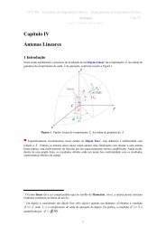
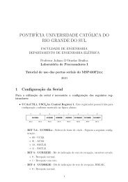
contained in Figure 1 is <strong>the</strong> speech signal ‘goat’, which contains<br />
two voiced phonemes /g/ <strong>and</strong> /oa/, followed by a partial closure of<br />
<strong>the</strong> vocal tract, <strong>and</strong> <strong>the</strong>n an unvoiced phoneme, /t/. The /g/, /oa/,<br />
<strong>and</strong> /t/ occur approximately at samples 3400-3900, 3900-5400,<br />
<strong>and</strong> 6300-6900, respectively.<br />
8 A-<strong>Law</strong> <strong>and</strong> <strong>mu</strong>-<strong>Law</strong> Comp<strong>and</strong>ing <strong>Implementations</strong> <strong>Using</strong> <strong>the</strong> TMS320C54x
SPRA163<br />
Figure 1. Sample Speech Signal: GOAT<br />
amplitude<br />
800<br />
600<br />
400<br />
200<br />
0<br />
-200<br />
-400<br />
-600<br />
-800<br />
-1000<br />
-1200<br />
/g/ /oa/ /t/<br />
3000 4000 5000<br />
sample<br />
6000 7000<br />
Each phoneme class brings its own stress to <strong>the</strong> telephone<br />
system. In general, <strong>the</strong> peak to peak amplitude of voiced<br />
phonemes is approximately ten times that of unvoiced <strong>and</strong> plosive<br />
phonemes, as clearly illustrated in Figure 1. As a result, <strong>the</strong><br />
telephone system <strong>mu</strong>st provide for a large range of signal<br />
amplitudes. Although lower in amplitude, unvoiced <strong>and</strong> plosive<br />
phonemes contain more information <strong>and</strong> thus, higher entropy <strong>the</strong>n<br />
voiced phonemes. Thus, <strong>the</strong> telephone system <strong>mu</strong>st provide<br />
higher resolution for lower amplitude signals.<br />
In addition to <strong>the</strong> tasks presented by <strong>the</strong> speech signal, <strong>the</strong><br />
telephone network is also subject to b<strong>and</strong>width restrictions with<br />
respect to <strong>the</strong> human speech <strong>and</strong> auditory ranges. The speech<br />
b<strong>and</strong>width for most adults is approximately 10 kHz. In contrast,<br />
<strong>the</strong> maxi<strong>mu</strong>m auditory range of humans is 20 kHz. This maxi<strong>mu</strong>m<br />
auditory range is usually limited to young children; instead, <strong>the</strong><br />
typical hearing b<strong>and</strong>width for most adults is 15 kHz.<br />
Of <strong>the</strong> speech <strong>and</strong> auditory b<strong>and</strong>widths, <strong>the</strong> telephone network<br />
restricts transmission to a 3 kHz portion, from .3 to 3.3 kHz. This<br />
frequency range is believed to coincide with <strong>the</strong> region of greatest<br />
intelligible speech, retaining only <strong>the</strong> first three formant<br />
frequencies of <strong>the</strong> sampled speech signal. This reduced<br />
b<strong>and</strong>width is <strong>the</strong>n surrounded by unused space from 0 to .3 kHz<br />
<strong>and</strong> from 3.3 to 4 kHz. This unused space, known as <strong>the</strong> guard<br />
b<strong>and</strong>, provides a buffer against conversation interference.<br />
Summing <strong>the</strong> transmission <strong>and</strong> guard b<strong>and</strong>s, <strong>the</strong> telephone<br />
network has a total b<strong>and</strong>width of 4 kHz.<br />
A-<strong>Law</strong> <strong>and</strong> <strong>mu</strong>-<strong>Law</strong> Comp<strong>and</strong>ing <strong>Implementations</strong> <strong>Using</strong> <strong>the</strong> TMS320C54x 9
SPRA163<br />
In summary, <strong>the</strong> telephone system <strong>mu</strong>st provide adequate quality<br />
for small amplitude signals consisting of unvoiced phonemes.<br />
Concurrently, <strong>the</strong> telephone system <strong>mu</strong>st provide for transmission<br />
of a wide range of signal amplitudes, due to <strong>the</strong> occasional<br />
occurrence of high energy voiced phonemes. The<br />
accomplishment of <strong>the</strong>se concurrent tasks, within a limited<br />
b<strong>and</strong>width, may be achieved via Pulse Code Modulation <strong>and</strong><br />
comp<strong>and</strong>ing, as discussed in <strong>the</strong> following section.<br />
Pulse Code Modulation <strong>and</strong> Comp<strong>and</strong>ing<br />
At <strong>the</strong> telephone transmitter, human speech is converted to<br />
analog signals. For digital transmission, this analog signal is<br />
converted to a digital signal, which has a fixed precision. To<br />
provide higher voice quality at a lower cost, <strong>the</strong> analog signals<br />
may be converted to digital signals using Pulse Code Modulation<br />
(PCM).<br />
PCM is composed of three successive steps: sampling, quantizing<br />
<strong>and</strong> coding. Sampling is <strong>the</strong> determination of a signal’s amplitude<br />
at regular time intervals. Since <strong>the</strong> telephone network has a<br />
b<strong>and</strong>width of 4 kHz, for accurate reproduction, a voice signal <strong>mu</strong>st<br />
be sampled at a rate of at least 8 kHz, according to Nyquist’s<br />
<strong>the</strong>orem. That is, <strong>the</strong> amplitude of <strong>the</strong> signal is sampled every 125<br />
μs. Once <strong>the</strong> signal’s amplitude is obtained, it is quantized into a<br />
discrete set of amplitude levels for representation as a digital<br />
signal. Quantization is achieved by dividing <strong>the</strong> b<strong>and</strong>width of <strong>the</strong><br />
system into quantization intervals, also known as bins. All signal<br />
amplitudes falling within a bin are represented by <strong>the</strong> midpoint of<br />
that quantization interval. The quantization process introduces<br />
quantization error into <strong>the</strong> digital signal; however, <strong>the</strong> introduced<br />
error may be minimized by minimizing <strong>the</strong> width of <strong>the</strong> bins with<br />
respect to <strong>the</strong> number of bits needed to uniquely identify <strong>the</strong><br />
quantization bins. Finally, coding of <strong>the</strong> signal is performed by<br />
converting <strong>the</strong> midpoint of each quantization level to a codeword.<br />
In general, speech signals are composed of relatively fewer<br />
voiced phonemes than unvoiced phonemes. Unfortunately, <strong>the</strong><br />
uniform quantizer, which has equally spaced zones, provides<br />
unneeded quality for large signals which are least likely to occur,<br />
<strong>and</strong> pronounced truncation effects for <strong>the</strong> more frequent small<br />
amplitude signals. As a result, uniform quantization does not<br />
perform as well as a quantizer with wider zones at high amplitudes<br />
<strong>and</strong> narrower zones at lower amplitudes.<br />
Instead of employing uniform quantization, a natural non-uniform<br />
substitute is observed in <strong>the</strong> human auditory system. It is believed<br />
that <strong>the</strong> human auditory system is a logarithmic process in which<br />
high amplitude sound does not require <strong>the</strong> same resolution as low<br />
amplitude sound.<br />
10 A-<strong>Law</strong> <strong>and</strong> <strong>mu</strong>-<strong>Law</strong> Comp<strong>and</strong>ing <strong>Implementations</strong> <strong>Using</strong> <strong>the</strong> TMS320C54x
SPRA163<br />
μ-<strong>Law</strong> Comp<strong>and</strong>ing<br />
Conversion to a logarithmic scale allows quantization intervals to<br />
increase with amplitude, <strong>and</strong> it insures that low-amplitude signals<br />
are digitized with a minimal loss of fidelity. Fewer bits per sample<br />
are necessary to provide a specified signal-to-noise ratio (SNR)<br />
for small signals <strong>and</strong> an adequate dynamic range for large signals.<br />
Non-uniform quantization may be achieved by first passing <strong>the</strong><br />
message through a compressor, a nonlinear device which<br />
compresses <strong>the</strong> peak amplitudes. This is followed by a uniform<br />
quantizer, such that uniform zones at <strong>the</strong> output correspond to<br />
non-uniform zones at <strong>the</strong> input. At <strong>the</strong> receiving end, <strong>the</strong><br />
compressed signal is passed through an exp<strong>and</strong>er, ano<strong>the</strong>r<br />
nonlinear device used to cancel <strong>the</strong> nonlinear effect of <strong>the</strong><br />
compressor. The combined process is known as comp<strong>and</strong>ing.<br />
In addition to reducing quantization error, comp<strong>and</strong>ing decreases<br />
<strong>the</strong> required b<strong>and</strong>width of <strong>the</strong> system. That is, systems solely<br />
employing uniform quantization require 13-bit codewords for<br />
equivalent performance requirements of <strong>the</strong> telephone system.<br />
However, while increasing performance, systems using nonlinear<br />
comp<strong>and</strong>ing may reduce <strong>the</strong> required codeword length to 8-bits or<br />
less.<br />
Comp<strong>and</strong>ing is simply a system in which information is<br />
compressed, flowed through a channel <strong>and</strong> <strong>the</strong>n exp<strong>and</strong>ed on <strong>the</strong><br />
o<strong>the</strong>r side. Comp<strong>and</strong>ing may be accomplished in hardware via a<br />
CODEC, or in software using a look-up table approach or a realtime<br />
direct calculation. However, if hardware comp<strong>and</strong>ing is<br />
implemented <strong>and</strong> intermediate processing of <strong>the</strong> signal is<br />
necessary, <strong>the</strong>n reverse comp<strong>and</strong>ing is required.<br />
Two international comp<strong>and</strong>ing st<strong>and</strong>ards that retain up to 5 bits of<br />
precision by encoding signal data into 8 bits are μ-law <strong>and</strong> A-law.<br />
μ-law is <strong>the</strong> accepted st<strong>and</strong>ard of <strong>the</strong> U.S. <strong>and</strong> Japan, while A-law<br />
is <strong>the</strong> European accepted st<strong>and</strong>ard. Both international st<strong>and</strong>ards<br />
are discussed fur<strong>the</strong>r in <strong>the</strong> following sections.<br />
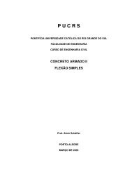
The U.S. <strong>and</strong> Japan use μ-law comp<strong>and</strong>ing. Limiting sample<br />
values to 13 magnitude bits, <strong>the</strong> μ-law compression portion of this<br />
st<strong>and</strong>ard is defined ma<strong>the</strong>matically by <strong>the</strong> continuous equation:<br />
F(x) = sgn(x) ln(1 + μ |x|) / ln (1 + μ) Equation (1)<br />
-1≤ x ≤ 1<br />
where μ is <strong>the</strong> compression parameter (μ=255 for <strong>the</strong> U.S. <strong>and</strong><br />
Japan), <strong>and</strong> x is <strong>the</strong> normalized integer to be compressed. A<br />
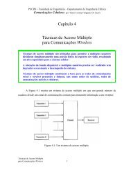
piece-wise linear approximation to this compression equation is<br />
illustrated in Figure 2.<br />
A-<strong>Law</strong> <strong>and</strong> <strong>mu</strong>-<strong>Law</strong> Comp<strong>and</strong>ing <strong>Implementations</strong> <strong>Using</strong> <strong>the</strong> TMS320C54x 11
Figure 2. μ-law Comp<strong>and</strong>ing Curve<br />
Comp<strong>and</strong>ed<br />
Signal<br />
μ = 255<br />
128<br />
112<br />
96<br />
80<br />
64<br />
48<br />
32<br />
16<br />
0<br />
0 1/8 1/4 3/8 1/2 5/8 3/4 7/8 1<br />
Normalized Input<br />
SPRA163<br />
1<br />
0.875<br />
0.75<br />
0.625<br />
0.5<br />
0.375<br />
12 A-<strong>Law</strong> <strong>and</strong> <strong>mu</strong>-<strong>Law</strong> Comp<strong>and</strong>ing <strong>Implementations</strong> <strong>Using</strong> <strong>the</strong> TMS320C54x<br />
0.25<br />
0.125<br />
0<br />
Normalized<br />
Output<br />
During compression, <strong>the</strong> least significant bits of large amplitude<br />
values are discarded. The number of insignificant bits deleted is<br />
encoded into a special field of <strong>the</strong> compressed code format, called<br />
<strong>the</strong> chord. Each chord of <strong>the</strong> piece-wise linear approximation is<br />
divided into equally sized quantization intervals called steps. The<br />
step size between adjacent codewords is doubled in each<br />
succeeding chord. Also encoded is <strong>the</strong> sign of <strong>the</strong> original integer.<br />
The polarity bit is set to 1 for positive integer values. Thus, an 8 bit<br />
μ-255 codeword is composed of 1 polarity bit concatenated with a<br />
3-bit chord concatenated with a 4-bit step.<br />
Before chord determination, <strong>the</strong> sign of <strong>the</strong> original integer is<br />
removed <strong>and</strong> a bias of 33 is added to <strong>the</strong> absolute value of <strong>the</strong><br />
integer. Due to <strong>the</strong> bias, <strong>the</strong> magnitude of <strong>the</strong> largest valid sample<br />
is reduced to 8159 <strong>and</strong> <strong>the</strong> mini<strong>mu</strong>m step size is reduced to<br />
2/8159. The added bias enables <strong>the</strong> endpoints of each chord to<br />
become powers of two, which in turn simplifies <strong>the</strong> determination<br />
of <strong>the</strong> chord <strong>and</strong> step. Chord determination may be reduced to<br />
finding <strong>the</strong> most significant 1 bit of <strong>the</strong> binary representation of <strong>the</strong><br />
biased integer value, while <strong>the</strong> step equals <strong>the</strong> four bits following<br />
<strong>the</strong> most significant 1.<br />
Illustrated in Table 1 is <strong>the</strong> translation from linear to μ-law<br />
compressed data. Of <strong>the</strong> compressed codeword, bits 4-6<br />
represent <strong>the</strong> chord <strong>and</strong> bits 0-3 represent <strong>the</strong> step. The polarity<br />
bit of <strong>the</strong> compressed codeword is not shown in this table.
SPRA163<br />
Table 1. μ-law Binary Encoding Table.<br />
Biased Input Values Compressed Code Word<br />
Chord Step<br />
bit: 12 11 10 9 8 7 6 5 4 3 2 1 0 bit: 6 5 4 3 2 1 0<br />
0 0 0 0 0 0 0 1 a b c d x 0 0 0 a b c d<br />
0 0 0 0 0 0 1 a b c d x x 0 0 1 a b c d<br />
0 0 0 0 0 1 a b c d x x x 0 1 0 a b c d<br />
0 0 0 0 1 a b c d x x x x 0 1 1 a b c d<br />
0 0 0 1 a b c d x x x x x 1 0 0 a b c d<br />
0 0 1 a b c d x x x x x x 1 0 1 a b c d<br />
0 1 a b c d x x x x x x x 1 1 0 a b c d<br />
1 a b c d x x x x x x x x 1 1 1 a b c d<br />
Finally, before transmission, <strong>the</strong> entire μ-law code is inverted. The<br />
codeword is inverted since low amplitude signals tend to be more<br />
numerous than large amplitude signals. Consequently, inverting<br />
<strong>the</strong> bits increases <strong>the</strong> density of positive pulses on <strong>the</strong><br />
transmission line, which improves <strong>the</strong> hardware performance.<br />
μ-law expansion is defined by <strong>the</strong> continuous inverse equation:<br />
F -1 (y) = sgn(y) (1 / μ) [(1+ μ) |y| - 1] Equation(2)<br />
-1 ≤ y ≤ 1<br />
Before expansion, <strong>the</strong> μ-law code is inverted again to restore <strong>the</strong><br />
original code. During expansion, <strong>the</strong> discarded least significant<br />
bits are approximated by <strong>the</strong> median of <strong>the</strong> interval, to reduce <strong>the</strong><br />
loss in accuracy. That is, if six of <strong>the</strong> least significant bits of <strong>the</strong><br />
original binary integer were discarded during compression, <strong>the</strong>se<br />
six least significant bits will be approximated by 1000002 during<br />
expansion. The μ-law binary decoding table used for expansion is<br />
given in Table 2. Again, <strong>the</strong> polarity bit is not shown in this table.<br />
After decoding <strong>the</strong> μ-law code, <strong>the</strong> bias is removed <strong>and</strong> <strong>the</strong> sign of<br />
<strong>the</strong> binary integer is restored according to <strong>the</strong> polarity bit.<br />
A-<strong>Law</strong> <strong>and</strong> <strong>mu</strong>-<strong>Law</strong> Comp<strong>and</strong>ing <strong>Implementations</strong> <strong>Using</strong> <strong>the</strong> TMS320C54x 13
Table 2. μ-law Binary Decoding Table<br />
Compressed Code Word Biased Output Values<br />
Chord Step<br />
bit: 6 5 4 3 2 1 0 bit: 12 11 10 9 8 7 6 5 4 3 2 1 0<br />
A-<strong>Law</strong> Comp<strong>and</strong>ing<br />
0 0 0 a b c d 0 0 0 0 0 0 0 1 a b c d 1<br />
0 0 1 a b c d 0 0 0 0 0 0 1 a b c d 1 0<br />
0 1 0 a b c d 0 0 0 0 0 1 a b c d 1 0 0<br />
0 1 1 a b c d 0 0 0 0 1 a b c d 1 0 0 0<br />
1 0 0 a b c d 0 0 0 1 a b c d 1 0 0 0 0<br />
1 0 1 a b c d 0 0 1 a b c d 1 0 0 0 0 0<br />
1 1 0 a b c d 0 1 a b c d 1 0 0 0 0 0 0<br />
1 1 1 a b c d 1 a b c d 1 0 0 0 0 0 0 0<br />
SPRA163<br />
The dynamic range of a comp<strong>and</strong>er may be defined as <strong>the</strong><br />
difference in signal power between <strong>the</strong> lowest amplitude<br />
occupying <strong>the</strong> entire range of <strong>the</strong> first chord <strong>and</strong> <strong>the</strong> highest<br />
occurring amplitude. 2 <strong>Using</strong> this definition, <strong>the</strong> dynamic range of μlaw<br />
comp<strong>and</strong>ing is calculated by Equation 3:<br />
DR = 20 log10 (8159/31) = 48.4 dB Equation(3)<br />
where 8159 is <strong>the</strong> largest amplitude possible, <strong>and</strong> 31 is <strong>the</strong> lowest<br />
amplitude spanning <strong>the</strong> first chord.<br />
To fur<strong>the</strong>r clarify <strong>the</strong> μ-law comp<strong>and</strong>ing process, several sample<br />
conversions from integer values, represented in sign-magnitude<br />
form, to μ-law codewords, <strong>and</strong> vice versa, are given in Appendix<br />
A.<br />
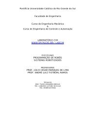
A-law is <strong>the</strong> CCITT recommended comp<strong>and</strong>ing st<strong>and</strong>ard used<br />
across Europe. Limiting sample values to 12 magnitude bits, <strong>the</strong><br />
compression portion of this st<strong>and</strong>ard is defined in <strong>the</strong> continuous<br />
Equation 4:<br />
Equation (4)<br />
F(x) = sgn(x) A |x| / (1 + lnA) 0 ≤ |x| < 1/A<br />
= sgn(x) (1+ln A|x|) /(1 + lnA) 1/A ≤ |x| ≤ 1<br />
where A is <strong>the</strong> compression parameter (A=87.6 in Europe), <strong>and</strong> x<br />
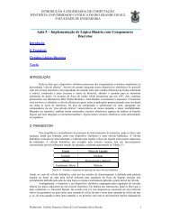
is <strong>the</strong> normalized integer to be compressed. A piece-wise linear<br />
approximation to this compression equation is illustrated in Figure<br />
3.<br />
14 A-<strong>Law</strong> <strong>and</strong> <strong>mu</strong>-<strong>Law</strong> Comp<strong>and</strong>ing <strong>Implementations</strong> <strong>Using</strong> <strong>the</strong> TMS320C54x
SPRA163<br />
Figure 3. A-law Comp<strong>and</strong>ing Curve<br />
Comp<strong>and</strong>ed<br />
Signal<br />
Α = 87 87.6<br />
128<br />
112<br />
96<br />
80<br />
64<br />
48<br />
32<br />
16<br />
0<br />
0 1/8 1/4 3/8 1/2 5/8 3/4 7/8 1<br />
Normalized Input<br />
1<br />
0.875<br />
0.75<br />
0.625<br />
0.5<br />
0.375<br />
A-<strong>Law</strong> <strong>and</strong> <strong>mu</strong>-<strong>Law</strong> Comp<strong>and</strong>ing <strong>Implementations</strong> <strong>Using</strong> <strong>the</strong> TMS320C54x 15<br />
0.25<br />
0.125<br />
0<br />
Normalized<br />
Output<br />
A-law comp<strong>and</strong>ing has <strong>the</strong> same basic features <strong>and</strong><br />
implementation advantages as μ-law comp<strong>and</strong>ing. A-law<br />
comp<strong>and</strong>ing is approximated by linear segments, with <strong>the</strong> first<br />
chord defined to be exactly linear. A zero-level output for <strong>the</strong> first<br />
quantization interval is not defined. Although biasing of <strong>the</strong> integer<br />
is not required before conversion, <strong>the</strong> maxi<strong>mu</strong>m integer value is<br />
reduced to 4096. Due to <strong>the</strong> larger mini<strong>mu</strong>m step size of 2/4096,<br />
which yields higher quantization error, A-law comp<strong>and</strong>ing<br />
produces small amplitude signals of lower quality than μ-law<br />
comp<strong>and</strong>ing. However, <strong>the</strong> dynamic range of A-law comp<strong>and</strong>ing is<br />
slightly higher than μ-law, as shown by Equation 5:<br />
DR = 20 log10 (4096/15) = 48.7 dB Equation (5)<br />
where 15 is <strong>the</strong> lowest amplitude spanning <strong>the</strong> first chord.<br />
The two comp<strong>and</strong>ing st<strong>and</strong>ards may also be compared with<br />
respect to precision of <strong>the</strong>ir binary integer representations. As<br />
stated previously, retained during comp<strong>and</strong>ing are up to 5 bits of<br />
precision: <strong>the</strong> 4-bit step, <strong>and</strong> <strong>the</strong> leading 1 (with <strong>the</strong> exception of<br />
values within chord 0). Thus, for μ-law comp<strong>and</strong>ing, up to 8 bits of<br />
precision are lost, while a maxi<strong>mu</strong>m of 7 bits of precision are lost<br />
for A-law comp<strong>and</strong>ing.<br />
Upon initial consideration, two procedures may be necessary for<br />
A-law chord determination, due to <strong>the</strong> linear definition of <strong>the</strong> first<br />
chord. For binary integers of magnitude greater than 1F16, <strong>the</strong><br />
procedure employed in chord <strong>and</strong> step determination for μ -law<br />
compression may be implemented. For binary integers of<br />
magnitude less than or equal to 1F16, <strong>the</strong> chord is equal to 000<br />
<strong>and</strong> <strong>the</strong> step is equal to <strong>the</strong> resulting 4 least significant bits after<br />
dividing <strong>the</strong> integer magnitude by 2.
Table 3. A-law Binary Encoding Table<br />
SPRA163<br />
Illustrated in Table 3 is <strong>the</strong> translation from linear to A-law<br />
compressed data. Of <strong>the</strong> compressed codeword, bits 4-6<br />
represent <strong>the</strong> chord <strong>and</strong> bits 0-3 represent <strong>the</strong> step. Only <strong>the</strong><br />
magnitudes of <strong>the</strong> input values <strong>and</strong> compressed codewords are<br />
shown; <strong>the</strong> sign extension of <strong>the</strong> input value <strong>and</strong> <strong>the</strong> polarity bit of<br />
<strong>the</strong> compressed codeword have been omitted.<br />
Once <strong>the</strong> chord <strong>and</strong> step have been determined, <strong>the</strong> polarity of <strong>the</strong><br />
original integer is determined. That is, if <strong>the</strong> original integer value<br />
is negative, <strong>the</strong> polarity bit 7 is set to 1; o<strong>the</strong>rwise, <strong>the</strong> polarity bit 7<br />
is cleared to 0.<br />
Input Values Compressed Code Word<br />
Chord Step<br />
bit:11 10 9 8 7 6 5 4 3 2 1 0 bit: 6 5 4 3 2 1 0<br />
0 0 0 0 0 0 0 a b c d x 0 0 0 a b c d<br />
0 0 0 0 0 0 1 a b c d x 0 0 1 a b c d<br />
0 0 0 0 0 1 a b c d x x 0 1 0 a b c d<br />
0 0 0 0 1 a b c d x x x 0 1 1 a b c d<br />
0 0 0 1 a b c d x x x x 1 0 0 a b c d<br />
0 0 1 a b c d x x x x x 1 0 1 a b c d<br />
0 1 a b c d x x x x x x 1 1 0 a b c d<br />
1 a b c d x x x x x x x 1 1 1 a b c d<br />
Again, to improve hardware performance, an inversion pattern is<br />
applied to <strong>the</strong> codeword before transmission. For A-law<br />
comp<strong>and</strong>ing, <strong>the</strong> pattern is every o<strong>the</strong>r bit starting with bit 0,<br />
where bit 0 is <strong>the</strong> rightmost bit as illustrated in Table 3.<br />
A-law expansion is defined by <strong>the</strong> continuous inverse equation:<br />
Equation (6)<br />
F -1 (y) = sgn(y) |y| [1+ ln(A] / A, 0 ≤|y|≤ 1/(1+ln(A))<br />
= sgn(y) e (|y|[1+ln(A)] - 1) / [A+ A ln(A)], 1/(1+ln(A)) ≤ |y| ≤ 1<br />
Before expansion, <strong>the</strong> inversion pattern is reapplied to <strong>the</strong> A-law<br />
code to restore <strong>the</strong> original code. As in μ-law expansion, <strong>the</strong> least<br />
significant bits discarded during compression are approximated by<br />
<strong>the</strong> median of <strong>the</strong> interval, to reduce loss in accuracy. The A-law<br />
binary decoding table used for expansion is given in Table 4. The<br />
polarity bit is not shown in this table. After decoding <strong>the</strong> A-law<br />
code, <strong>the</strong> sign of <strong>the</strong> integer is restored according to <strong>the</strong> polarity<br />
bit.<br />
16 A-<strong>Law</strong> <strong>and</strong> <strong>mu</strong>-<strong>Law</strong> Comp<strong>and</strong>ing <strong>Implementations</strong> <strong>Using</strong> <strong>the</strong> TMS320C54x
SPRA163<br />
Table 4. A-law Binary Decoding Table<br />
Compressed Code Word Biased Output Values<br />
Chord Step<br />
bit: 6 5 4 3 2 1 0 bit: 11 10 9 8 7 6 5 4 3 2 1 0<br />
0 0 0 a b c d 0 0 0 0 0 0 0 a b c d 1<br />
0 0 1 a b c d 0 0 0 0 0 0 1 a b c d 1<br />
0 1 0 a b c d 0 0 0 0 0 1 a b c d 1 0<br />
0 1 1 a b c d 0 0 0 0 1 a b c d 1 0 0<br />
1 0 0 a b c d 0 0 0 1 a b c d 1 0 0 0<br />
1 0 1 a b c d 0 0 1 a b c d 1 0 0 0 0<br />
1 1 0 a b c d 0 1 a b c d 1 0 0 0 0 0<br />
1 1 1 a b c d 1 a b c d 1 0 0 0 0 0 0<br />
To fur<strong>the</strong>r clarify <strong>the</strong> A-law comp<strong>and</strong>ing process, several sample<br />
conversions from integer values to A-law codewords <strong>and</strong> from Alaw<br />
codewords back to integer values are given in Appendix A.<br />
A-<strong>Law</strong> <strong>and</strong> <strong>mu</strong>-<strong>Law</strong> Comp<strong>and</strong>ing <strong>Implementations</strong> <strong>Using</strong> <strong>the</strong> TMS320C54x 17
Implementation <strong>Using</strong> <strong>the</strong> TMS320C54X<br />
SPRA163<br />
The TMS320C54x implementations make use of <strong>the</strong> EXP <strong>and</strong><br />
NORM instructions. These instructions allow <strong>the</strong> extraction of <strong>the</strong><br />
most significant bits without requiring a look-up table, thus saving<br />
memory. The EXP instruction computes <strong>the</strong> exponent value,<br />
which is in <strong>the</strong> range of -8 to +31, <strong>and</strong> stores <strong>the</strong> result in <strong>the</strong> T<br />
register. This is based on <strong>the</strong> most significant bit in <strong>the</strong><br />
accu<strong>mu</strong>lator. The exponent is determined by subtracting 8 from<br />
<strong>the</strong> number of leading bits in <strong>the</strong> 40-bit source accu<strong>mu</strong>lator (with<br />
<strong>the</strong> exception of <strong>the</strong> sign bit).<br />
The NORM instruction performs a single-cycle normalization of<br />
<strong>the</strong> accu<strong>mu</strong>lator, based on <strong>the</strong> 6 least significant bits of <strong>the</strong> T<br />
register, interpreted as a 2’s complement number. Since <strong>the</strong><br />
shifter is loaded with <strong>the</strong> contents of <strong>the</strong> T register during <strong>the</strong> read<br />
phase, <strong>the</strong>re <strong>mu</strong>st be at least 1 cycle between <strong>the</strong> EXP <strong>and</strong><br />
NORM instructions, for proper normalization <strong>and</strong> avoidance of a<br />
pipeline conflict.<br />
Fur<strong>the</strong>r discussion of system requirements with respect to coding<br />
schemes <strong>and</strong> <strong>the</strong> TSM320C54x is presented in <strong>the</strong> following<br />
section. Also presented are <strong>the</strong> actual coding schemes<br />
implemented for μ-law <strong>and</strong> A-law comp<strong>and</strong>ing.<br />
System Requirements vs. Coding Scheme<br />
The major issues involved in coding comp<strong>and</strong>ing routines are<br />
program overhead, required memory, <strong>and</strong> speed. The effect of<br />
program overhead, consisting of context saving <strong>and</strong> restoring,<br />
depends upon how <strong>the</strong> routines are invoked, <strong>and</strong> which registers<br />
are accessed by <strong>the</strong> o<strong>the</strong>r procedures involved in <strong>the</strong> system. If<br />
<strong>the</strong> initialized registers are not used by <strong>the</strong> o<strong>the</strong>r system<br />
procedures, initialization is performed only once; o<strong>the</strong>rwise, <strong>the</strong><br />
registers involved <strong>mu</strong>st be saved before <strong>and</strong> restored after<br />
execution of <strong>the</strong> comp<strong>and</strong>ing routine. Included in <strong>the</strong> required<br />
memory is <strong>the</strong> program code, any initialization code resulting in<br />
program overhead, <strong>and</strong> any necessary data variables. The goal is<br />
to obtain routines with mini<strong>mu</strong>m overhead <strong>and</strong> mini<strong>mu</strong>m required<br />
memory that execute at maxi<strong>mu</strong>m speed.<br />
18 A-<strong>Law</strong> <strong>and</strong> <strong>mu</strong>-<strong>Law</strong> Comp<strong>and</strong>ing <strong>Implementations</strong> <strong>Using</strong> <strong>the</strong> TMS320C54x
SPRA163<br />
Comp<strong>and</strong>ing may be performed using a look-up table method, or<br />
by direct implementation. Each approach has its advantages <strong>and</strong><br />
disadvantages with respect to <strong>the</strong> previously mentioned issues.<br />
The look-up table method requires mini<strong>mu</strong>m timing (3 cycles), but<br />
it is memory intensive. To perform compression <strong>and</strong> expansion, in<br />
addition to <strong>the</strong> program memory, two 256-word tables are<br />
necessary. Coding consists of loading <strong>the</strong> starting table address<br />
into a register, adding <strong>the</strong> data sample as an offset into <strong>the</strong> table,<br />
<strong>and</strong> retrieving <strong>the</strong> codeword or data at <strong>the</strong> offset address. In<br />
addition, significant overhead is required for building <strong>the</strong> tables in<br />
memory. However, this overhead is reduced for those<br />
TMS320C54x devices with on-chip ROM containing <strong>the</strong> expansion<br />
tables (‘C542).<br />
Comp<strong>and</strong>ing by direct implementation may be facilitated using<br />
ma<strong>the</strong>matical equations, often called direct encoding, or by<br />
invoking simplified algorithms. Ei<strong>the</strong>r method of direct<br />
implementation limits <strong>the</strong> required memory to that of <strong>the</strong> coded<br />
program, while program overhead is reduced to register<br />
initializations. However, most often, memory <strong>and</strong> overhead<br />
reductions are achieved at <strong>the</strong> expense of increased cycle times.<br />
The choice of comp<strong>and</strong>ing approaches ultimately depends upon<br />
<strong>the</strong> system’s performance requirements. The method selected for<br />
this application note is <strong>the</strong> direct implementation approach using a<br />
simplified algorithm. As will be shown, an attempt is made to<br />
minimize <strong>the</strong> tradeoff between required memory <strong>and</strong> cycle time,<br />
that is, comp<strong>and</strong>ing by direct implementation is achieved using 16<br />
to 21 words requiring only 10 to 13 cycles.<br />
Reduced overhead or increased performance may be achieved by<br />
combining <strong>the</strong> comp<strong>and</strong>ing routines with o<strong>the</strong>r necessary<br />
functions of <strong>the</strong> overall system. As a result, <strong>the</strong> described routines<br />
only contain <strong>the</strong> necessary code for conversion; polling of <strong>the</strong><br />
samples is not performed.<br />
When implementing <strong>the</strong> described comp<strong>and</strong>ing routines, <strong>the</strong><br />
following assumptions <strong>and</strong> suggestions should be considered. It is<br />
assumed that <strong>the</strong> incoming samples are scaled appropriately,<br />
prior to execution, <strong>and</strong> <strong>the</strong> sign extension mode is selected. For<br />
opti<strong>mu</strong>m performance, suggested is <strong>the</strong> use of <strong>the</strong> memorymapped<br />
ports for <strong>the</strong> incoming samples. In addition, <strong>the</strong> program<br />
<strong>and</strong> data words should be placed in single-cycle memory.<br />
The following sections contain detailed discussions of each<br />
routine; <strong>the</strong> TMS320C54x assembly source code files are located<br />
in Appendix B.<br />
A-<strong>Law</strong> <strong>and</strong> <strong>mu</strong>-<strong>Law</strong> Comp<strong>and</strong>ing <strong>Implementations</strong> <strong>Using</strong> <strong>the</strong> TMS320C54x 19
μ-law Compression<br />
μ-law compression may be defined by Equation 7.<br />
μ-code = μsgn + μchd + μstep Equation (7)<br />
SPRA163<br />
As stated earlier, <strong>the</strong> sample values are limited to 13 magnitude<br />
bits, <strong>and</strong> sign extension mode is selected. When an integer<br />
sample is loaded into <strong>the</strong> A accu<strong>mu</strong>lator, <strong>the</strong> sign bit is extended<br />
through <strong>the</strong> upper accu<strong>mu</strong>lator <strong>and</strong> guard bits. Letting AH<br />
represent bits 16-31 of <strong>the</strong> upper A accu<strong>mu</strong>lator, <strong>the</strong> sign of <strong>the</strong><br />
sample may be positioned into bit 7 of <strong>the</strong> μ-code by <strong>the</strong> following<br />
equation:<br />
μsgn = (AH * -1)
SPRA163<br />
Finally, μ-code of Equation 7 is obtained by combining Equations<br />
9, 10 <strong>and</strong> 11:<br />
Equation (12)<br />
μ−code = AH * FF8016+ 19016 - (T|EXP)*16<br />
+ ([(|int| + 33) > 26) - 1016<br />
Evident from Equation 12 is that <strong>the</strong> removal of <strong>the</strong> leading 1 in<br />
<strong>the</strong> μstep calculation is unnecessary if a biased μchd* equation is<br />
implemented. Thus <strong>the</strong> implemented μchd* <strong>and</strong> μstep* equations<br />
become:<br />
<strong>and</strong><br />
μchd* = 18016 - (T|EXP)*16 Equation (13)<br />
μstep* = ( [ (|int| + 33) > 26) Equation (14)<br />
Ano<strong>the</strong>r simplification implemented in this algorithm involves <strong>the</strong><br />
inversion of <strong>the</strong> 8-bit μ−code for transmission. Inversion of an 8-bit<br />
μ−code is equivalent to:<br />
Equation (15)<br />
μ-code' = FF16 - μ-code = FF16 - μsgn - μchd - μstep<br />
Substituting Equations 9, 10 <strong>and</strong> 11, Equation 7 becomes:<br />
Equation (16)<br />
μ-code' = FF16 - AH * FF8016 - 18016 + (T|EXP)*16<br />
- ( [(|int|+ 33) > 26)<br />
The final result of <strong>the</strong> μ−law compression algorithm is stored in <strong>the</strong><br />
lower 7 bits of <strong>the</strong> B accu<strong>mu</strong>lator.<br />
The μ−law compression algorithm requires 17 words of memory: 4<br />
words of data, 10 words of program <strong>and</strong> 3 words for program<br />
overhead. The overhead of this algorithm consists of loading <strong>the</strong><br />
data page pointer with <strong>the</strong> page containing <strong>the</strong> data words <strong>and</strong><br />
linking <strong>the</strong> AR0 pointer to <strong>the</strong> input sample. Assuming opti<strong>mu</strong>m<br />
conditions, <strong>the</strong> program contains 10 single-cycle instructions. For<br />
a 50 MIPS device, this results in a 200 Nsec execution time.<br />
Assuming an 8 kHz sampling rate, this algorithm requires only .08<br />
MIPS.<br />
A-<strong>Law</strong> <strong>and</strong> <strong>mu</strong>-<strong>Law</strong> Comp<strong>and</strong>ing <strong>Implementations</strong> <strong>Using</strong> <strong>the</strong> TMS320C54x 21
μ-law Expansion<br />
The μ−law expansion algorithm implements <strong>the</strong> following<br />
equation:<br />
SPRA163<br />
Equation (17)<br />
INTNUM = [(2 * μ−step + 33) * 2 μ−chd - 33] * sgn(μ−sgn)<br />
= [(2 * μ−step + 33)
SPRA163<br />
A-law Compression<br />
A-law compression may be described by <strong>the</strong> following equation:<br />
acode = asgn + achd + astep. Equation(19)<br />
A-law compression requires <strong>the</strong> concurrent determination of chord<br />
<strong>and</strong> step. After loading <strong>the</strong> integer into <strong>the</strong> B accu<strong>mu</strong>lator, <strong>the</strong> 6<br />
least significant bits are removed; <strong>the</strong> result is placed in <strong>the</strong> A<br />
accu<strong>mu</strong>lator. This removal facilitates a simplified routine for chord<br />
determination. Next, <strong>the</strong> EXP instruction is applied to <strong>the</strong> A<br />
accu<strong>mu</strong>lator, after which <strong>the</strong> T register will contain a value<br />
between 25 <strong>and</strong> 31. NOTE, however, that if <strong>the</strong> value in <strong>the</strong><br />
accu<strong>mu</strong>lator is zero, <strong>the</strong> EXP yields NO redundant sign bits. This<br />
results in a value of 0 in <strong>the</strong> T register. The accu<strong>mu</strong>lator is<br />
checked for a value of 0, in which case 1Fh (31) is written to <strong>the</strong> T<br />
register. The T register value is subtracted from <strong>the</strong> maxi<strong>mu</strong>m<br />
possible, 31, yielding chord values in <strong>the</strong> range of 0 to 6.<br />
However, <strong>the</strong> correct chord range is 0-7 <strong>and</strong> may be obtained by<br />
adding <strong>the</strong> leading 1 prior to <strong>the</strong> 4 step bits, if present, to this<br />
result.<br />
In determining <strong>the</strong> step, <strong>the</strong> sign of <strong>the</strong> original integer is removed<br />
<strong>and</strong> stored to bit 7 of <strong>the</strong> A accu<strong>mu</strong>lator. The magnitude of <strong>the</strong><br />
integer is normalized by <strong>the</strong> updated contents of <strong>the</strong> T register,<br />
after which, <strong>the</strong> step is contained in bits 32-35, <strong>and</strong> <strong>the</strong> leading 1,<br />
if present, is contained in bit 36, of <strong>the</strong> B accu<strong>mu</strong>lator. For true<br />
step determination, bits 32-35 are isolated <strong>and</strong> <strong>the</strong> chord<br />
calculation is completed by adding bit 36 of <strong>the</strong> B accu<strong>mu</strong>lator to<br />
<strong>the</strong> previous chord result.<br />
Letting T|EXP represent <strong>the</strong> contents of T after <strong>the</strong> EXP execution,<br />
<strong>and</strong> B36|NORM represent bit 36 of <strong>the</strong> B accu<strong>mu</strong>lator after <strong>the</strong><br />
NORM execution, <strong>the</strong> chord, step <strong>and</strong> sign calculations are<br />
described by Equations 20, 21 <strong>and</strong> 22 respectively:<br />
Equation (20)<br />
achd = (1F16 - T|EXP + B36|NORM )
SPRA163<br />
Finally, <strong>the</strong> even bits of <strong>the</strong> A-law codeword are inverted before<br />
transmission:<br />
acode* = acode XOR 5516<br />
Equation (24)<br />
<strong>and</strong> <strong>the</strong> compressed codeword is located in <strong>the</strong> lower 8 bits of<br />
accu<strong>mu</strong>lator A.<br />
The A−law compression algorithm requires 20 words of memory: 5<br />
words of data, 12 words of program <strong>and</strong> 3 words for program<br />
overhead. The overhead consists of loading <strong>the</strong> data page pointer<br />
with <strong>the</strong> page containing <strong>the</strong> dataword MASK, <strong>and</strong> linking <strong>the</strong> AR0<br />
pointer to <strong>the</strong> input sample. Assuming opti<strong>mu</strong>m conditions, <strong>the</strong><br />
program contains 12 single-cycle instructions. For a 50 MIPS<br />
device, this results in a 240 Nsec execution time, <strong>and</strong> assuming<br />
an 8 kHz sampling rate, this algorithm requires only .096 MIPS.<br />
24 A-<strong>Law</strong> <strong>and</strong> <strong>mu</strong>-<strong>Law</strong> Comp<strong>and</strong>ing <strong>Implementations</strong> <strong>Using</strong> <strong>the</strong> TMS320C54x
SPRA163<br />
A-law Expansion<br />
A-law expansion is defined by Equation 25:<br />
Equation (25)<br />
INTNUM = [(2*astep + 33)*2 achd - 32*δ(achd)] *sgn(asgn)<br />
= [(2*astep + 33)
Summary<br />
SPRA163<br />
Presented in this application note were comp<strong>and</strong>ing routines<br />
written for <strong>the</strong> TMS320C54x digital signal processor. Theoretical<br />
material regarding comp<strong>and</strong>ing, as well as detailed discussions of<br />
each algorithm, were included.<br />
When strictly dedicated to μ-law comp<strong>and</strong>ing, <strong>the</strong> TMS320C54x<br />
can compress or exp<strong>and</strong> 5 million words per second, assuming<br />
<strong>the</strong> samples for conversion are available in memory. For A-law<br />
comp<strong>and</strong>ing, compression at 4.16 million words per second is<br />
possible, but expansion is reduced to 3.84 million words per<br />
second. Possibly of greatest importance is <strong>the</strong> si<strong>mu</strong>ltaneous<br />
decrease in MIPS <strong>and</strong> memory requirements achieved by <strong>the</strong>se<br />
algorithms, as discussed previously <strong>and</strong> summarized in Table 5.<br />
Table 5. Comp<strong>and</strong>ing Algorithms Summary<br />
Memory Requirements<br />
Total Data Program Overhead MIPS<br />
μ-law compression 17 4 10 3 .080<br />
μ-law expansion 21 3 10 8 .080<br />
A-law compression 20 5 12 3 .096<br />
A-law expansion 21 5 13 3 .104<br />
26 A-<strong>Law</strong> <strong>and</strong> <strong>mu</strong>-<strong>Law</strong> Comp<strong>and</strong>ing <strong>Implementations</strong> <strong>Using</strong> <strong>the</strong> TMS320C54x
SPRA163<br />
Appendix A. Comp<strong>and</strong>ing Examples<br />
Table 6. μ-law Compression:<br />
Integer Biased Integer μ-code μ-code’<br />
−246010 = F66416<br />
= −99C16<br />
−150510 = FA1F16<br />
= −5E116<br />
−65010 = FD7616<br />
= −28A16<br />
−33810 = FEAE16<br />
= −15216<br />
−9010 = FFA616<br />
= −5A16<br />
−110<br />
= FFFF16<br />
= −116<br />
+10210 = 006616<br />
= +6616<br />
+16910 = 00A916<br />
= +A916<br />
+42010 = 01A416<br />
= +1A416<br />
+49910 = 01F316<br />
= +1F316<br />
+98010 = 03D416<br />
= +3D416<br />
+700010 = 1B5816<br />
= +1B5816<br />
→ −(99C16+2116 ) = −9BD16<br />
= (1)0 1001 1011 11012<br />
→ −(5E116+ 2116 ) = −60216<br />
= (1)0 0110 0000 00102<br />
→ −(28A16 +2116 ) = −2AB16<br />
= (1)0 0010 1010 10112<br />
→ −(15216 +2116 ) = −17316<br />
= (1)0 0001 0111 00112<br />
→ −(5A16+2116 ) = −7B16<br />
= (1)0 0000 0111 10112<br />
→ −(116 +2116 ) = −2216<br />
= (1)0 0000 0010 00102<br />
→ +(6616+2116 ) = +8716<br />
= (0)0 0000 1000 01112<br />
→ +(A916+2116) = +CA16<br />
= (0)0 0000 1100 10102<br />
→ +(1A416+2116) = +1C516<br />
= (0)0 0001 1100 01012<br />
→ +(1F316+2116 ) = +21416<br />
= (0)0 0010 0001 01002<br />
→ +(3D416+2116) = +3F516<br />
= (0)0 0011 1111 01012<br />
→ +(1B5816+2116) = +1B7916<br />
= (0)1 1011 0111 10012<br />
→ (1)110 00112<br />
=E316<br />
→ (1)101 10002<br />
=D816<br />
→ (1)100 01012<br />
=C516<br />
→ (1)011 01112<br />
=B716<br />
→ (1)001 11102<br />
=9E16<br />
→ (1)000 00012<br />
=8116<br />
→ (0)010 00002<br />
=2016<br />
→ (0)010 10012<br />
=2916<br />
→ (0)011 11002<br />
=3C16<br />
→ (0)100 00002<br />
=4016<br />
→ (0)100 11112<br />
=4F16<br />
→ (0)111 10112<br />
=7B16<br />
→ 1C16<br />
→ 2716<br />
→ 3A16<br />
→ 4816<br />
→ 6116<br />
→ 7E16<br />
→ DF16<br />
→ D616<br />
→ C316<br />
→ BF16<br />
→ B016<br />
→ 8416<br />
A-<strong>Law</strong> <strong>and</strong> <strong>mu</strong>-<strong>Law</strong> Comp<strong>and</strong>ing <strong>Implementations</strong> <strong>Using</strong> <strong>the</strong> TMS320C54x 27
SPRA163<br />
Table 7. μ-law Expansion: (shown in order as produced by compression table)<br />
μ-code’ μ-code Biased Integer Exp<strong>and</strong>ed Integer<br />
1C16 → E316 = → (1) 0 1001 1100 00002<br />
(1) 110 00112 = −9C016<br />
2716 → D816 = → (1) 0 0110 0010 00002<br />
(1) 101 10002 = −62016<br />
3A16 → C516 = → (1) 0 0010 1011 00002<br />
(1) 100 01012 = −2B016<br />
4816 → B716 = → (1) 0 0001 0111 10002<br />
(1) 011 01112 = −17816<br />
6116 → 9E16 = → (1) 0 0000 0111 10102<br />
(1) 001 11102 = −7A16<br />
7E16 → 8116 = → (1) 0 0000 0010 00112<br />
(1) 000 00012 = −2316<br />
DF16 → 2016 = → (0) 0 0000 1000 01002<br />
(0) 010 00002 = +8416<br />
D616 → 2916 = → (0) 0 0000 1100 11002<br />
(0) 010 10012 = +CC16<br />
C316 → 3C16 = → (0) 0 0001 1100 10002<br />
(0) 011 11002 = +1C816<br />
BF16 → 4016 = → (0) 0 0010 0001 00002<br />
(0) 100 00002 = +21016<br />
B016 → 4F16 = → (0) 0 0011 1111 00002<br />
(0) 100 11112 = +3F016<br />
8416 → 7B16 = → (0) 1 1011 1000 00002<br />
(0) 111 10112 = +1B8016<br />
→−(9C016 − 2116 ) = −99F16<br />
= F66116<br />
→−(62016 − 2116 ) = −5FF16<br />
= FA0116<br />
→−(2B016 − 2116 ) = −28F16<br />
= FD7116<br />
→−(17816 − 2116 ) = −15716<br />
= FEA916<br />
→−(7A16 − 2116 ) = −5916<br />
= FFA716<br />
→−(2316 − 2116 ) = −216<br />
= FFFE16<br />
→ +(8416 −2116) = +6316<br />
= 006316<br />
→ +(CC16 − 2116 ) = +AB16<br />
= 00AB16<br />
→ +(1C816 − 2116 ) = +1A716<br />
= 01A716<br />
→ +(21016 − 2116 ) = +1EF16<br />
= 01EF16<br />
→ +(3F016 − 2116 ) = +3CF16<br />
= 03CF16<br />
→ +(1B8016−2116 ) = +1B5F16<br />
= 1B5F16<br />
= −246310<br />
= −153510<br />
= −65510<br />
= −34310<br />
= −8910<br />
= −210<br />
= +9910<br />
= +17110<br />
= +42310<br />
= +49510<br />
= +97510<br />
= +700710<br />
28 A-<strong>Law</strong> <strong>and</strong> <strong>mu</strong>-<strong>Law</strong> Comp<strong>and</strong>ing <strong>Implementations</strong> <strong>Using</strong> <strong>the</strong> TMS320C54x
SPRA163<br />
Table 8. A-law Compression<br />
−246010 = F66416<br />
= −99C16<br />
−150510 = FA1F16<br />
= −5E116<br />
−65010 = FD7616<br />
= −28A16<br />
−33810 =FEAE16<br />
= −15216<br />
−9010 = FFA616<br />
= −5A16<br />
−110<br />
= FFFF16<br />
= −116<br />
+4010 = 002816<br />
= +2816<br />
+10210 = 006616<br />
= +6616<br />
+169 = 00A916<br />
= +A916<br />
+42010 = 01A416<br />
= +1A416<br />
+49910 = 01F316<br />
= +1F316<br />
+98010 = 03D416<br />
= +3D416<br />
Integer A-code A-code*<br />
→ (1) 1001 1001 11002 → (1) 111 00112 = F316 → A616<br />
→ (1) 0101 1110 00012 → (1) 110 01112 = E716 → B216<br />
→ (1) 0010 1000 10102 → (1) 101 01002 = D416 → 8116<br />
→ (1) 0001 0101 00102 → (1) 100 01012 = C516 → 9016<br />
→ (1) 0000 0101 10102 → (1) 010 01102 = A616 → F316<br />
→ (1) 0000 0000 00012 → (1) 000 00002 = 8016 → D516<br />
→ (0) 0000 0010 10002 → (0) 001 01002 = 1416 → 4116<br />
→ (0) 0000 0110 01102 → (0) 010 10012 = 2916 → 7C16<br />
→ (0) 0000 1010 10012 → (0) 011 01012 = 3516 → 6016<br />
→ (0) 0001 1010 01002 → (0) 100 10102 = 4A16 → 1F16<br />
→ (0) 0001 1111 00112 → (0) 100 11112 = 4F16 → 1A16<br />
→ (0) 0011 1101 01002 → (0) 101 11102 = 5E16 → 0B16<br />
A-<strong>Law</strong> <strong>and</strong> <strong>mu</strong>-<strong>Law</strong> Comp<strong>and</strong>ing <strong>Implementations</strong> <strong>Using</strong> <strong>the</strong> TMS320C54x 29
SPRA163<br />
Table 9. A-law Expansion (shown in order as produced by compression table)<br />
A-code* A-code Exp<strong>and</strong>ed Integer<br />
A616 → F316 = (1) 111 00112 → (1) 1001 1100 00002 → −9C016<br />
= F64016<br />
B216 → E716 = (1) 110 01112 → (1) 0101 1110 00002 → −5E016<br />
= FA2016<br />
8116 → D416 = (1) 101 01002 → (1) 0010 1001 00002 → −29016<br />
= FD7016<br />
9016 → C516 = (1) 100 01012 → (1) 0001 0101 10002 → −15816<br />
= FEA816<br />
F316 → A616 = (1) 010 01102 → (1) 0000 0101 10102 → −5A16<br />
= FFA616<br />
D516 → 8016 = (1) 000 00002 → (1) 0000 0000 00012 → −116<br />
= FFFF16<br />
4116 → 1416 = (0) 001 01002 → (0) 0000 0010 10012 → +2916<br />
= 002916<br />
7C16 → 2916 = (0) 010 10012 → (0) 0000 0110 01102 → +6616<br />
= 006616<br />
6016 → 3516 = (0) 011 01012 → (0) 0000 1010 11002 → +AC16<br />
= 00AC16<br />
1F16 → 4A16 = (0) 100 10102 → (0) 0001 1010 10002 → +1A816<br />
= 01A816<br />
1A16 → 4F16 = (0) 100 11112 → (0) 0001 1111 10002 → +1F816<br />
= 01F816<br />
0B16 → 5E16 = (0) 101 11102 → (0) 0011 1101 00002 → +3D016<br />
= 03D016<br />
= −249610<br />
= −150410<br />
= −65610<br />
= −34410<br />
= −9010<br />
= −110<br />
= +4110<br />
= +10210<br />
= +17210<br />
= +42410<br />
= +50410<br />
= +97610<br />
30 A-<strong>Law</strong> <strong>and</strong> <strong>mu</strong>-<strong>Law</strong> Comp<strong>and</strong>ing <strong>Implementations</strong> <strong>Using</strong> <strong>the</strong> TMS320C54x
SPRA163<br />
Appendix B. Comp<strong>and</strong>ing Code Listing<br />
μ-law Compression: int2<strong>mu</strong>.asm<br />
; INT2MU.ASM<br />
;<br />
; Integer originally loaded into A Accu<strong>mu</strong>lator<br />
; (Q13 number is assumed to be sign-extended to 16 bits)<br />
;<br />
; <strong>mu</strong>code = <strong>mu</strong>sign + <strong>mu</strong>chord + <strong>mu</strong>step<br />
;<br />
; <strong>mu</strong>chord = (19h - T|EXP)
NORM A ;A
SPRA163<br />
μ-law Expansion: <strong>mu</strong>2int.asm<br />
; MU2INT.ASM<br />
;<br />
;IMPLEMENT EQUATION<br />
;<br />
; <strong>mu</strong>code = <strong>mu</strong>sign : <strong>mu</strong>chord : <strong>mu</strong>step<br />
; X XXX XXXX<br />
;<br />
; INTNUM = [ ((2 * <strong>mu</strong>step + 33) AH<br />
AND A,8 ;REMOVE POLARITY BIT<br />
;(A
SPRA163<br />
A-law Compression: int2alaw.asm<br />
; INT2ALAW.ASM<br />
;<br />
; Integer originally loaded into B Accu<strong>mu</strong>lator<br />
; (Q12 number is assumed to be sign-extended to 16 bits)<br />
;<br />
; 6 LSB are <strong>the</strong>n striped off <strong>and</strong> <strong>the</strong> result is put in A<br />
;<br />
; acode = asgn + achord + astep<br />
;<br />
; achord = (1Fh - T|EXP + B36|NORM)
SPRA163<br />
A-law Expansion: alaw2int.asm<br />
; ALAW2INT.ASM<br />
;<br />
;IMPLEMENT EQUATION<br />
;<br />
; A-LAW = ASGN : ACHD : ASTEP<br />
; X XXX XXXX<br />
;<br />
; INTNUM = [ (2*ASTEP + 33)*2^(ACHD) - 32*DELTA(ACHD)] * SGN(ASGN)<br />
;<br />
; DELTA(ACHD) = 1 ACHD == 0<br />
; = 0 elsewhere<br />
;<br />
; Final output is stored in low accu<strong>mu</strong>lator B<br />
.def START<br />
.mmregs<br />
.sect aexpnd<br />
TABLE .word 0ah,0b2h,81h,90h,0f3h,0d5h,42h,65h,6ch,19h,05h,0a6h<br />
;TEST VALUES<br />
MASK1 .word 0ABh;(55h
SPRA163<br />
Appendix C. References<br />
Rabiner, L.R., Schafer R.W., Digital Processing of Speech<br />
Signals, Bell Laboratories, Inc., 1978.<br />
Bellamy, J., Digital Telephony, 2nd Edition, John Wiley &<br />
Sons, Inc., New York, 1991.<br />
Brokish, C., μ-law Compression on <strong>the</strong> TMS320C54x,<br />
TMS320 DSP Designer’s Notebook, Texas<br />
Instruments, 1996.<br />
Hambley, A.R., An Introduction to Com<strong>mu</strong>nication Systems,<br />
Computer Science Press, New York, 1990, pp.<br />
239-251.<br />
Pagnucco, L., Erskine C., Comp<strong>and</strong>ing Routines for <strong>the</strong><br />
TMS32010/TMS32020, DSP Applications with<br />
<strong>the</strong> TMS320 Family, Vol. 1, Texas Instruments,<br />
1989.<br />
Stremler, F. G., Introduction to Com<strong>mu</strong>nication Systems, 3rd<br />
Ed., Addison-Wesley Publishing Co., New<br />
York, 1990, pp.402-412, 541-547.<br />
36 A-<strong>Law</strong> <strong>and</strong> <strong>mu</strong>-<strong>Law</strong> Comp<strong>and</strong>ing <strong>Implementations</strong> <strong>Using</strong> <strong>the</strong> TMS320C54x
IMPORTANT NOTICE<br />
Texas Instruments <strong>and</strong> its subsidiaries (TI) reserve <strong>the</strong> right to make changes to <strong>the</strong>ir products or to discontinue<br />
any product or service without notice, <strong>and</strong> advise customers to obtain <strong>the</strong> latest version of relevant information<br />
to verify, before placing orders, that information being relied on is current <strong>and</strong> complete. All products are sold<br />
subject to <strong>the</strong> terms <strong>and</strong> conditions of sale supplied at <strong>the</strong> time of order acknowledgment, including those<br />
pertaining to warranty, patent infringement, <strong>and</strong> limitation of liability.<br />
TI warrants performance of its semiconductor products to <strong>the</strong> specifications applicable at <strong>the</strong> time of sale in<br />
accordance with TI’s st<strong>and</strong>ard warranty. Testing <strong>and</strong> o<strong>the</strong>r quality control techniques are utilized to <strong>the</strong> extent<br />
TI deems necessary to support this warranty. Specific testing of all parameters of each device is not necessarily<br />
performed, except those m<strong>and</strong>ated by government requirements.<br />
Customers are responsible for <strong>the</strong>ir applications using TI components.<br />
In order to minimize risks associated with <strong>the</strong> customer’s applications, adequate design <strong>and</strong> operating<br />
safeguards <strong>mu</strong>st be provided by <strong>the</strong> customer to minimize inherent or procedural hazards.<br />
TI assumes no liability for applications assistance or customer product design. TI does not warrant or represent<br />
that any license, ei<strong>the</strong>r express or implied, is granted under any patent right, copyright, mask work right, or o<strong>the</strong>r<br />
intellectual property right of TI covering or relating to any combination, machine, or process in which such<br />
semiconductor products or services might be or are used. TI’s publication of information regarding any third<br />
party’s products or services does not constitute TI’s approval, warranty or endorsement <strong>the</strong>reof.<br />
Copyright © 2000, Texas Instruments Incorporated