Error Correction Methods
Error Correction Methods
Error Correction Methods

Create successful ePaper yourself
Turn your PDF publications into a flip-book with our unique Google optimized e-Paper software.
Technologies and Services on Digital Broadcasting (7)<br />
<strong>Error</strong> <strong>Correction</strong> <strong>Methods</strong><br />
"Technologies and Services of Digital Broadcasting" (in Japanese, ISBN4-339-01162-2) is published by<br />
CORONA publishing co., Ltd. Copying, reprinting, translation, or retransmission of this document is<br />
prohibited without the permission of the authors and the publishers, CORONA publishing co., Ltd. and NHK.<br />
1. Digital Transmission and <strong>Error</strong><br />
<strong>Correction</strong><br />
<strong>Error</strong> correction technology, with which the errors that<br />
occur during transmission are corrected, is essential when<br />
high-quality digital video and audio are to be provided in<br />
digital broadcasting The principle of error correction is that<br />
the improvement in the reliability of the received<br />
information as a result of error correction will more than<br />
compensate for the increase in data caused by the addition<br />
of redundant data in the coding process.<br />
The channel capacity C (bps) for a digital transmission<br />
channel of bandwidth B (Hz) on which errors are caused by<br />
random noise can be given by the following equation<br />
(Shannon's theorem) 1) :<br />
(1)<br />
where S is signal power (W), N is noise power (W), and<br />
N0 is noise power spectral density (W/Hz). Shannon's<br />
theorem says that coding for which data can be<br />
transmitted without errors will exist so long as the<br />
transmission rate does not exceed this channel capacity.<br />
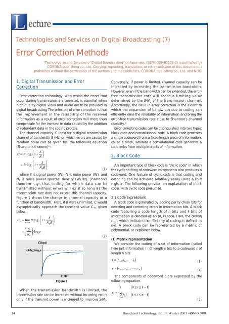
Figure 1 shows the change in channel capacity as a<br />
function of bandwidth. Here, if B were unlimited, C would<br />
asymptotically approach the constant value C given<br />
below.<br />
(S/N 0)log 2e<br />
C(bps)<br />
0 B(Hz)<br />
Figure 1<br />
When the transmission bandwidth is limited, the<br />
transmission rate can be increased without incurring errors<br />
only if the transmit power is increased to improve S/N 0.<br />
(2)<br />
Conversely, if power is limited, channel capacity can be<br />
increased by increasing the transmission bandwidth.<br />
However, even if the bandwidth can be extended, the errorfree<br />
transmission rate will reach a limiting value<br />
determined by the S/N 0 of the transmission channel.<br />
Accordingly, the issue in error correction is the extent to<br />
which the expansion of bandwidth due to coding can<br />
efficiently raise the reliability of information and bring the<br />
error-free transmission rate close to Shannon's channel<br />
capacity. 2)<br />
<strong>Error</strong> correcting codes can be distinguished into two types:<br />
block code and convolutional code. A block code generates<br />
a single codeword from a fixed-length piece of information,<br />
called a block, whereas a convolutional code generates a<br />
code series from multiple blocks of information.<br />
2. Block Code<br />
An important type of block code is "cyclic code" in which<br />
the cyclic shifting of codeword components also produces a<br />
codeword. One feature of cyclic code is that coding and<br />
decoding can be achieved relatively easily using a shift<br />
register. The following provides an explanation of block<br />
codes, with cyclic code presumed.<br />
2.1 Code expressions<br />
A block code is generated by adding parity check bits for<br />
detecting and correcting errors in information bits. A block<br />
code featuring a code length of n bits and k bits of<br />
information is denoted as an (n, k) code. Here, the coding<br />
rate, which indicates the efficiency of coding, is defined as<br />
k/n. A block code can be represented by a matrix or<br />
polynomial, as explained below.<br />
(1) Matrix representation<br />
We consider the coding of a set of information (called<br />
here just information ) i of length k bits to a codeword c of<br />
length n bits.<br />
(4)<br />
The components of codeword c are expressed by the<br />
following equation.<br />
14 Broadcast Technology no.13, Winter 2003 C NHK STRL<br />
(3)<br />
(5)
Here, h ij indicates the coefficients (components of the<br />
matrix expression) in the linear sums used for calculating<br />
parity check bits for the information. The value of h ij is 0 or<br />
1. All sums here are Exclusive OR operations.<br />
Denoting the number of parity bits as m (= n-k), the<br />
matrix relating the codeword and information is as<br />
follows.<br />
This k n matrix consisting of a k<br />
(6)<br />
k unit matrix and<br />
coefficients hij is called a generator matrix. A matrix H of<br />
order m k is created by permutating the components of<br />
the generator matrix as follows.<br />
(7)<br />
H is called a parity check matrix.<br />
The decoding side calculates a "syndrome" by<br />
multiplying the received words by the transpose matrix of<br />
H. The size of the syndrome is only m bits, the same as the<br />
number of parity check bits. <strong>Error</strong>s can be inferred from the<br />
pattern of this m-bit syndrome since the pattern has a oneto-one<br />
correspondence with the error locations.<br />
(2) Polynomial representation<br />
If the length of a block code is long, the matrix<br />
representation can be difficult to handle, and a<br />
polynomial expression may be more convenient.<br />
Letting each bit of the information and codeword be a<br />
coefficient of a polynomial, we get the following equations.<br />
(9)<br />
Equations (8) and (9) are related as follows using a<br />
polynomial g(x) of degree m (= n-k).<br />
g(x) is called a generator polynomial.<br />
feed back corresponding to g(x)<br />
i(x)<br />
shift register<br />
for getting B(x)<br />
SW2<br />
SW1<br />
c(x)<br />
(8)<br />
(10)<br />
received<br />
word<br />
However, simply multiplying the information<br />
polynomial i(x) by g(x) does not preserve the information's<br />
original form within the codeword. The following<br />
operation is therefore necessary.<br />
First, the product of the information polynomial i(x) and<br />
xm can be expressed as follows, where A(x) and B(x) are the<br />
quotient polynomial and residual polynomial,<br />
respectively, obtained by dividing that product by g(x).<br />
(11)<br />
Since g(x) is of degree m, A(x) and B(x) become<br />
polynomials of degrees k-1 or less and m-1 or less,<br />
respectively, and can be denoted as follows.<br />
The codeword polynomial c(x) becomes<br />
(a) encoding (b) decoding<br />
Lecture<br />
(12)<br />
(13)<br />
(14)<br />
As shown by Eq. (14), the codeword polynomial has the<br />
information in its original form in k bits of the higher<br />
degree terms. This kind of code is called a "systematic<br />
code".<br />
The codeword polynomial has the property of being<br />
divisible by the generator polynomial. This means that a<br />
received word in which an error has been added to the<br />
codeword cannot be divided evenly by the generator<br />
polynomial. The residual polynomial obtained by dividing<br />
the received word polynomial by the generator polynomial<br />
becomes the syndrome polynomial s(x) as a result. The<br />
pattern of this syndrome polynomial has a one-to-one<br />
relationship with that of the errors and can therefore be<br />
used to correct them.<br />
2.2 Coding and decoding<br />
Figure 2 shows coding and decoding configurations for a<br />
cyclic code using shift registers.<br />
In the coding circuit of Fig. 2(a), SW1 is initially set to<br />
its lower position so that the k bits of information are<br />
output in their original form. SW2 is set in the closed<br />
feed back corresponding to g(x)<br />
syndorome register<br />
error pattern detection<br />
received word buffer register<br />
Figure 2: Coding and decoding configurations for a cyclic code<br />
correction<br />
output<br />
Broadcast Technology no.13, Winter 2003 C NHK STRL<br />
15
position to perform shifting while receiving feedback<br />
corresponding to the generator polynomial. This<br />
shifting determines the residual polynomial B(x)<br />
obtained by dividing the product of i(x) and x m by g(x).<br />
The coefficients of B(x) are left in the shift register after<br />
the above k bits have been output. At this point in time,<br />
SW1 is set to its upper position, SW2 is set in an open<br />
position, and the coefficients of B(x) are output in order<br />
from the shift register to complete the codeword.<br />
Next, in the decoding circuit of Fig. 2(b), the received<br />
word is simultaneously input to the buffer register and the<br />
syndrome register. The latter register is used to calculate<br />
the residual polynomial obtained by dividing the received<br />
word by the generator polynomial. Once all bits of the<br />
received word have been input, the absence of error in the<br />
received word can be inferred if the syndrome register<br />
contains only zeros.<br />
In error correction, when the value of the syndrome<br />
register corresponds to a pattern in which the leading bit of<br />
the received word is erroneous, that bit will be corrected<br />
and then output. The feedback bit of the syndrome register<br />
will also be corrected at this time. This operation repeats<br />
until all data in the received-word buffer register have been<br />
output.<br />
2.3 Galois field<br />
The concept of a Galois field is important when thinking<br />
about block codes in mathematical terms. A Galois field is<br />
a set with a finite number of elements that can be added,<br />
subtracted, multiplied, and divided (except by 0). A Galois<br />
field of q elements is denoted as GF(q ).<br />
Accordingly, a Galois field cannot have an arbitrary<br />
(infinite) number of elements. Furthermore, the number of<br />
elements q must be of the form pm, where p is a prime<br />
number and m is a positive integer. A field whose number<br />
of elements is equal to a prime number is called a prime<br />
field and one whose number of elements is equal to a<br />
power of a prime is called an extension field of a base<br />
prime field. Of particular importance to error correcting<br />
code is the prime field GF(2) for the prime number 2 and its<br />
extension field GF(2m). There are two elements in GF(2): 0 and 1. These elements<br />
can be subjected to the four algebraic operations in the<br />
same way as an integer with the provision that any result<br />
equal to 2 or greater takes on the remainder of that result<br />
divided by 2. This means that addition in GF(2) is an<br />
Exclusive OR operation.<br />
When deriving an extension field from a certain<br />
prime field, the field is expanded by adding on the<br />
roots of an irreducible polynomial. This is similar to<br />
affixing root i (imaginary unit) of the irreducible<br />
polynomial x2 +1=0 to a real number when deriving a<br />
complex number field from a real number field. For<br />
example, in deriving GF(2 8 ) from GF(2), the 256<br />
elements of GF(2 8 2 254<br />
) would be 0, 1, , , ..., , where<br />
is a root of the irreducible polynomial x 8 +x 4 +x 3 +x 2 +1=0.<br />
In a block code, digital data corresponds to the elements<br />
of a Galois field, and coding and decoding are performed<br />
by operating on those elements.<br />
2.4 Examples of block codes<br />
(1) Bose-Chaudhuri-Hocquenghem (BCH) code3)4) The BCH code is used in a variety of applications due to<br />
its especially strong ability for correcting random errors as<br />
well as its wide range of code lengths. The following<br />
describes a 2-element (binary) BCH code that handles data<br />
on GF(2).<br />
Denoting the number of bits that can be corrected within<br />
one block as t, then, for any positive integer m, a BCH code<br />
with code length n of 2 m -1 and parity length k of mt or less<br />
can be generated. Now, given that one element of the<br />
Galois field GF(2 m ) is , the minimal polynomial over<br />
2 2t<br />
GF(2) having , , ..., as roots becomes the generator<br />
polynomial of the BCH code.<br />
i<br />
However, because a polynomial over GF(2) also has to<br />
2i<br />
the second power, that is, , as a root as well, the roots of<br />
the generator polynomial of BCH code may be the t roots<br />
3 2t-1<br />
, , ..., of odd powers only. The generator<br />
polynomial of BCH code is consequently defined by the<br />
following expression:<br />
(15)<br />
where mi(x) is the minimal polynomial over GF(2)<br />
i<br />
having as a root and LCM[ ] indicates the least common<br />
multiple polynomial. Table 1 shows examples of generator<br />
polynomials for 2-element BCH code.<br />
(2) Reed-Solomon code 5)<br />
The Reed-Solomon (RS) code performs data coding and<br />
decoding in units of multiple bits (byte). Consequently,<br />
while the 2-element BCH code described in the previous<br />
section processes data in bit units of GF(2), the extension of<br />
this to a GF(2 m ) extension field is the RS code.<br />
Given that is one element of GF(2 m ), the generator<br />
polynomial of RS code for correcting up to t bytes within a<br />
block is defined as follows:<br />
(16)<br />
where code length is 2 m -1 bytes or less and parity length is<br />
2t bytes. In contrast to a 2-element code, where polynomial<br />
16 Broadcast Technology no.13, Winter 2003 C NHK STRL<br />
n<br />
7<br />
15<br />
31<br />
63<br />
k<br />
4<br />
11<br />
7<br />
26<br />
16<br />
57<br />
39<br />
t<br />
1<br />
1<br />
2<br />
1<br />
3<br />
1<br />
4<br />
Table 1<br />
generator polynomials<br />
x3 +x+1<br />
x4 +x+1<br />
x8 +x7 +x6 +x4 +1<br />
x5 +x2 +1<br />
x15 +x11 +x10 +x9 +x8 +x7 +x5 +x3 +x2 +x+1<br />
x6 +x+1<br />
x24 +x23 +x22 +x20 +x19 +x17 +x16 +x13 +x10 +x9 +x8 +x6 +x5 +x4 +x2 +x+1
coefficients are the elements of GF(2) and roots are the<br />
elements of GF(2 m ), in the case of RS code, both polynomial<br />
coefficients and roots are the elements of GF(2 m ).<br />
Reed Solomon coding is performed in a manner similar<br />
to that of 2-element code, that is, the parity check bytes are<br />
taken to be the residual polynomial obtained by dividing<br />
the product of the information polynomial and x m by the<br />
generator polynomial.<br />
Decoding is performed as a 5-step process of error<br />
correction: syndrome calculation, derivation of the error<br />
locator polynomial and error evaluator polynomial, error<br />
locator calculation, and error value calculation.<br />
1) Syndrome calculation<br />
The first step in determining the location of errors in the<br />
received data and their values is to calculate syndromes<br />
from the received word, where the number of syndromes is<br />
the same as the number of parity bytes. The received word<br />
polynomial is described as follows.<br />
(17)<br />
i<br />
Substituting the root (i=0,1,...,2t-1) of the generator<br />
polynomial in the received word polynomial gives us the<br />
syndrome si as follows.<br />
(18)<br />
This can be calculated by repeated multiplication and<br />
addition, as shown in Fig. 3.<br />
rn-1 , ...r 1 , r 0<br />
Figure 3<br />
2) Derivation of error locator polynomial and error<br />
evaluator polynomial<br />
Assuming that errors in the received word have occurred<br />
in the j1, j2,...,jl bytes from high-order bytes of the received<br />
word, we consider a polynomial (z), whose roots are the<br />
inverse of roots<br />
includes errors ei.<br />
j1<br />
,<br />
j2<br />
,...,<br />
jl<br />
, and a polynomial (z) that<br />
(19)<br />
The polynomials (z) and<br />
(20)<br />
(z) are called the error<br />
locator polynomial and error evaluator polynomial,<br />
respectively.<br />
D<br />
S i<br />
The syndrome polynomial S(z) is defined as follows.<br />
Lecture<br />
(21)<br />
S(z) is related to (z) and (z) in the following way.<br />
(22)<br />
The error locator polynomial (z) and error evaluator<br />
polynomial (z) are derived in the process of determining<br />
the greatest common divisor polynomial of S(z) and z 2t by<br />
the Euclidean division algorithm.<br />
The process of deriving (z) and (z) by the Euclidean<br />
division algorithm is shown in Fig. 4.<br />
3) <strong>Error</strong> locator calculation<br />
Because the error locator polynomial's roots have<br />
degrees inverse to those of the error locations, we can<br />
-1<br />
substitute (i=0,...,n-1) in order in the error locator<br />
polynomial to get the following equation from which i,<br />
that is, the error locations, can be determined by the<br />
Chien search algorithm shown in Fig. 5.<br />
(23)<br />
The (z) coefficients 1,..., l are set in each register as<br />
initial values. Shifting is then performed in sequence, and<br />
the number of shifts needed for the sum total of registeroutputs<br />
to be zero indicates the error location.<br />
4) <strong>Error</strong> value calculation<br />
Once the error locations j 1,j 2,...,j l are known, we substitute<br />
-j i in the error evaluator polynomial (z) and obtain the<br />
following expression.<br />
Broadcast Technology no.13, Winter 2003 C NHK STRL<br />
17<br />
Start<br />
B -1(z)=0 B 0(z)=1<br />
R -1(z)=z 2t R 0(z)=S(z)<br />
i=1<br />
Q i(z)=R i-2(z)/R i-1(z)<br />
R i(z)=R i-2(z)-Q i(z)R i-1(z)<br />
B i(z)=B i-2(z)-Q i(z)B i-2(z)<br />
deg R i(z) t-1<br />
Yes<br />
(z)=B i(z)/B i(0)<br />
(z)=R i(z)/B i(0)<br />
End<br />
Figure 4<br />
No<br />
i=i+1
This can be rewritten as follows.<br />
l<br />
2<br />
1<br />
D<br />
D<br />
D<br />
l<br />
2<br />
Figure 5<br />
(24)<br />
(25)<br />
The error values e j1,e j2,...,e jl at locations j 1,j 2,...,j l can thus<br />
be calculated.<br />
5) <strong>Error</strong> correction<br />
Erroneous bites are corrected by adding error values<br />
e j1,e j2,...,e jl to bytes corresponding to error locations j 1,j 2,...,j l<br />
of the received word.<br />
Because data in digital broadcasts are transmitted in<br />
units of transport stream (TS) packets in MPEG-2 systems,<br />
coding will be performed by either (204, 188) RS coding for<br />
every 188-byte TS packet or by (207, 187) RS coding for<br />
every 187 bytes, excluding one synchronizing byte at the<br />
beginning of the TS packet.<br />
(3) Difference-set cyclic code 6)<br />
In block code error correction, the existence of an error is<br />
typically determined by calculating syndromes from<br />
received words. However, if the block length is long and the<br />
number of parity bits is large, the number of syndrome<br />
patterns will be enormous, forcing an increase in the scale<br />
of the decoding circuit. In this regard, a decoding method<br />
that enables a decoding circuit to be configured in a<br />
relatively simple manner is "majority logic decoding."<br />
Majority logic decoding calculates several syndrome<br />
sums and examines the results of those sums to determine<br />
whether 0 or 1 is in the majority. <strong>Error</strong> correction is<br />
performed if there are more 1's than 0's. Such a syndrome<br />
sum is called a "parity check sum."<br />
An example of majority logic decodable code is the<br />
"difference-set cyclic code." This code is so named because it<br />
is derived from a set of numbers called a "perfect difference<br />
1<br />
set."<br />
A perfect difference set is a set of integers such that<br />
(26)<br />
Specifically, given a set D having J (= q +1) integers, we<br />
can define difference as follows.<br />
(27)<br />
D is called a perfect difference set if satisfies to<br />
below.<br />
The positive values of are all different.<br />
The negative values of are all different.<br />
For negative , q(q+1)+1+ does not equal the<br />
absolute value of .<br />
The polynomial for which the powers of its terms<br />
correspond to the integers of a perfect difference set is<br />
expressed as follows.<br />
(28)<br />
Furthermore, g(x) of the difference-set cyclic code is given<br />
as follows:<br />
(29)<br />
where n is the code length and GCD[ ] indicates the<br />
greatest common divisor polynomial.<br />
Given that J denotes the number of integers in a perfect<br />
difference set, a difference-set cyclic code with good<br />
efficiency can be derived for J=2 s +1, where s is any positive<br />
integer. The block length n is 2 2s +2 s +1 bits, parity length k<br />
is 3 s +1 bits, and the number of parity check sums is J. In<br />
addition, the number of bits t that can be corrected within<br />
one block is (J - 1)/2 bits. Table 2 shows the generator<br />
polynomials and perfect difference sets of the difference-set<br />
cyclic code.<br />
Figure 6 shows an example of majority logic decoding in<br />
the difference-set cyclic code.<br />
Referring to the figure, the bits of the received word will<br />
be corrected if there are more 1's than 0's among the three<br />
parity check sums (A 1, A 2, A 3).<br />
s n k j t<br />
1 7 3 3 1<br />
2 21 11 5 2<br />
3 73 45 9 4<br />
18 Broadcast Technology no.13, Winter 2003 C NHK STRL<br />
4<br />
5<br />
273<br />
1057<br />
191<br />
813<br />
17<br />
33<br />
8<br />
16<br />
Table 2<br />
generator<br />
polynomials<br />
x 4 +x 3 +x 2 +1<br />
x 10 +x 7 +x 6 +x 4 +x 2 +1<br />
x 28 +x 25 +x 22 +x 16 +x 12<br />
+x 8 +x 6 +x 4 +x 2 +1<br />
x 82 +x 77 +x 76 +x 71 +x 67<br />
+x 66 +x 56 +x 52 +x 48 +x 40<br />
+x 36 +x 34 +x 24 +x 22 +x 18<br />
+x 10 +x 4 +1<br />
(omitted)<br />
perfect difference<br />
sets<br />
0,1,3<br />
0,2,7,8,11<br />
0,2,10,24,25,29,36,42,<br />
45<br />
0,18,24,46,50,67,103,<br />
112,115,126,128,159,<br />
166,167,186,196,201<br />
0,1,3,7,15,31,54,63,<br />
109,127,138,219,255,<br />
277,298,338,348,439,<br />
452,511,528,555,597,<br />
677,697,702,754,792,<br />
879,905,924,990,1023
parity check sum<br />
receiver<br />
A 1 A 2 A 3<br />
majority logic<br />
(if 1 is majority, then correct)<br />
Figure 6<br />
In majority logic decoding, there is also a way to<br />
improve error correcting performance beyond<br />
conventional levels by devising a particular means of<br />
decoding. This decoding method is called "variable<br />
threshold majority logic decoding." In ordinary majority<br />
logic decoding, error correction is performed if the number<br />
of 1's is greater than the threshold value T=J/2 for J parity<br />
check sums. In variable threshold majority logic decoding,<br />
decoding is performed recursively, starting with a threshold<br />
value of T>J/2 and continuing until T=J/2 while decreasing<br />
T by 1 each cycle. This decoding method improves error<br />
correcting performance by correcting bits with a high<br />
possibility of error first.<br />
3. Convolutional Code<br />
corrected<br />
output<br />
correction<br />
In contrast to block code, convolutional code is difficult<br />
to handle from a mathematical point of view since it refers<br />
to past information bits to determine the codewords. It is<br />
nevertheless a useful error correcting code in practice and<br />
has found a wide range of application. The following<br />
describes convolutional coding and decoding (Viterbi<br />
decoding algorithm) on the basis of a simple example.<br />
3.1 Convolutional coding<br />
We consider the simple example of convolutional code<br />
shown in Fig. 7. Here, the coding rate is 1/2 because two<br />
bits of output data are generated for every one bit of input<br />
data. Specifically, two bits of code c 1 and c 2 are generated<br />
from one bit of input data a 1 and two bits of previously<br />
input data a 2 and a 3 left in the registers. In other words, all<br />
c 1= a 1+a 3<br />
input a1 a2 a3 output<br />
c 2= a 1+a 2+a 3<br />
Figure 7<br />
Lecture<br />
output values are systematically determined by the value<br />
of one input bit and the values of the two previous bits.<br />
The number of registers in the coding circuit is called the<br />
constraint length of the convolutional code.<br />
Denoting each of the possible states determined by the<br />
values of the two bits left in the coding circuit registers as A<br />
(a 2=0, a 3=0), B (a 2=1, a 3=0), C (a 2=0, a 3=1), and D (a 2=1,<br />
a 3=1), the transitions from each of these states to a<br />
following state due to input bit a 1 can be represented by<br />
the state transition diagram shown in Fig. 8.<br />
3.2 Viterbi decoding 7)<br />
Viterbi decoding is one method of decoding<br />
convolutional code. It corrects errors by observing the<br />
received data series and determining the code series closest<br />
to that data series. As an example, we consider the<br />
information series (1 0 1 0 1 0 0) input to the coding circuit<br />
of Fig. 7. Here, the last two bits of the information series are<br />
dummy bits used for terminating decoding, and the code<br />
series output from the coding circuit is (11 01 00 01 00 01<br />
11). The received series, moreover, is assumed to be (01 00<br />
00 01 00 01 11) in which two bits, the 1st and 4th bit, are<br />
different as a result of errors incurred on the transmission<br />
channel.<br />
We explain the decoding algorithm by using the Trellis<br />
diagram shown in Fig. 9. This diagram shows the<br />
transitions that can be made between the states described<br />
above. Starting from state A, we calculate the total number<br />
of bits that differ between the code output and the received<br />
series for each path of the Trellis diagram. This total<br />
number of different bits is called the "Hamming distance."<br />
In the figure, the numerical values within the circles for<br />
each state indicate the total Hamming distance with<br />
respect to the received series up to that point on the path.<br />
In this process, two paths enter each state but only the one<br />
with the smaller distance survives. This remaining path is<br />
called the "survivor." In this example, the above operation<br />
is performed until the paths converge to state A as a result<br />
of the dummy bits making up the last two bits of the<br />
information series.<br />
Consequently, the path with the smallest total Hamming<br />
distance (A B C B C B C A) survives. The<br />
transmitted information series can be inferred to be (1 0 1 0<br />
1 0 0), and the result of decoding is correct despite the<br />
occurrence of two transmission errors. Correcting errors in<br />
Broadcast Technology no.13, Winter 2003 C NHK STRL<br />
19<br />
c 1c 2/a 1<br />
11/1<br />
B<br />
00/0<br />
01/0<br />
01/1<br />
A D<br />
00/1<br />
C<br />
10/1<br />
11/0 10/0<br />
Figure 8
00/0<br />
1<br />
11/1<br />
this way, by making an efficient search for the closest code<br />
series using a Trellis diagram, is Viterbi decoding.<br />
The above example presented a case in which dummy<br />
bits are added to the information series to be transmitted to<br />
indicate termination of decoding. In general, however, a<br />
path is selected when reaching a path of fixed length on<br />
the decoding side without adding dummy bits. In this case,<br />
the path length terminating decoding must be five or six<br />
times the code constraint length.<br />
<strong>Error</strong> correcting performance can be improved by using<br />
the results of a multi-value judgment (soft decision) made<br />
on the received signal as a value for selecting the surviving<br />
path instead of the Hamming distance, which is<br />
determined from binary data (hard decision). For example,<br />
by dividing binary data (0, 1) into 8-level data<br />
(011,010,001,000,100,101,110,111) represented in three<br />
bits according to the magnitude of that received signal, the<br />
reliability of that binary data can be applied to the<br />
decoding process. Because Viterbi decoding selects a<br />
survivor by quantifying the difference between each path<br />
and the received series and comparing their totals, a soft<br />
decision is relatively easy to apply. Viterbi decoding with a<br />
soft decision improves characteristics by about 2 dB over<br />
those of hard-decision decoding.<br />
3.3 Punctured coding<br />
The coding rate of a convolutional code can be modified<br />
by a "punctured coding" that systematically removes data<br />
from the code series to be transmitted. On the receive side,<br />
information<br />
information 1 0 1 0 1 0 0<br />
convolutional code 11 01 00 01 00 01 11<br />
received code 01 00 00 01 00 01 11<br />
coder<br />
(r=1/2)<br />
state A<br />
state B<br />
state C<br />
state D<br />
punctuation<br />
rate<br />
3/4<br />
7/8<br />
Figure 10<br />
1<br />
eraser pattern<br />
1 0<br />
101<br />
1111010<br />
1000101<br />
00/0<br />
11/1<br />
1<br />
00/0<br />
11/1<br />
1<br />
00/0<br />
11/1<br />
2<br />
00/0<br />
11/1<br />
3<br />
00/0<br />
3<br />
00/0<br />
2<br />
11/0 11/0 11/0 11/0 11/0<br />
3 2 2 2<br />
01/0 00/1 00/1 00/1<br />
01/0 01/0 01/0 01/0<br />
2 3 2 3 2<br />
10/0 10/0<br />
10/1<br />
10/0<br />
10/1 10/1 10/1 10/0<br />
2<br />
01/1<br />
3<br />
01/1<br />
3<br />
01/1<br />
3<br />
punctuation<br />
code<br />
Figure 9<br />
the removed data can be ignored and decoding can be<br />
performed by a decoder identical to the one for the original<br />
convolutional code. Figure 10 shows examples of data<br />
removing patterns when creating code with coding rates of<br />
3/4 and 7/8 from convolutional code of coding rate 1/2.<br />
While punctured coding increases transmission<br />
efficiency, the uncertainty in selecting the survivor<br />
increases with the amount of removed data, and thus,<br />
error correcting performance deteriorates. Figure 11 shows<br />
the error correcting characteristics at coding rates of 1/2,<br />
3/4, and 7/8 for convolutional code.<br />
4. Concatenated Coding 8)<br />
When applying error correcting code to actual digital<br />
broadcasting systems, error correction may be applied<br />
twice to the digital data to be transmitted in a process<br />
called concatenated coding.<br />
In particular, concatenated coding that combines code<br />
over GF(p) and code over GF(p m ) has been found to be<br />
effective. We give an example of concatenated coding that<br />
combines convolutional code over GF(2) and RS code over<br />
GF(2 8 ), as used in actual digital broadcasting systems and<br />
20 Broadcast Technology no.13, Winter 2003 C NHK STRL<br />
BER<br />
10 -1<br />
10 -2<br />
10 -3<br />
10 -4<br />
10 -5<br />
r=1/2 3/4 7/8<br />
PSK<br />
no-coding<br />
10-6 2 3 4 5 6 7 8 9 10<br />
Eb /N0 (dB)<br />
Figure 11
transmission data<br />
received data<br />
BER<br />
10 -1<br />
10 -2<br />
10 -3<br />
10 -4<br />
10 -5<br />
RS encode interleave<br />
RS decode deinterleave<br />
convolutional code<br />
+ (204, 188) RS code<br />
r=1/2 3/4 7/8<br />
PSK<br />
no-coding<br />
10-6 1 2 3 4 5 6<br />
Eb /N0 (dB)<br />
Figure 13<br />
Figure 12<br />
convolutional<br />
encode<br />
convolutional<br />
decode<br />
(Viterbi decode)<br />
modulation<br />
demodulation<br />
Lecture<br />
program-material transmission systems.<br />
Figure 12 shows the flow of basic concatenated coding.<br />
The convolutional code is called the "inner code" and the<br />
RS code the "outer code." In addition, considering that the<br />
error after Viterbi decoding of the inner code generally<br />
occurs in burst form, burst-error diffusion processing is<br />
performed by adding an interleaving function between the<br />
inner and outer codes. In this example, byte interleaving is<br />
performed in units of 8 bits, since the outer code is RS code<br />
over GF(2 8 ). Figure 13 shows the bit error rate (BER)<br />
characteristics when using a convolutional code with<br />
coding rates 1/2, 3/4, and 7/8 as the inner code and<br />
(204,188) RS code as the outer code. (Dr. Shigeki Moriyama)<br />
References<br />
1) Shannon, C.E.: A Mathematical Theory of Communication, Bell System Tech. J., Vol. 27, pp. 379-423, pp. 623-656 (1948)<br />
2) Peterson, W.W. and Weldon, E.J.,Jr.: <strong>Error</strong>-Correcting Codes, 2nd ed., MIT press (1972)<br />
3) Hocquenghem, A.: Codes Correcteurs d'Erreurs, Chiffres, Vol. 2, pp. 147-156 (1959)<br />
4) Bose, R.C. and Ray-Chaudhure, D.K.: On a Class of <strong>Error</strong> Correcting Binary Group Codes, Inform. and Control, Vol. 3, pp. 68-79<br />
(1960)<br />
5) Reed, I.S. and Solomon, G.: Polynomial Codes over Certain Finite Fields, J.Soc.Indust.Apply.Math., Vol. 8, pp. 300-304 (1960)<br />
6) Weldom, E.J., Jr.: Difference-Set Cyclic Codes, Bell System Tech. J., Vol. 45, pp. 1045-1055 (1996)<br />
7) Viterbi, A.J.: <strong>Error</strong> Bounds for Convolutional Codes and an Asymptotically Optimum Decoding Algorithm, IEEE Trans. Inform.<br />
Theory, Vol. IT-13, pp. 260-269 (1967)<br />
8) Forney, G.D., Jr.: Concatenated Codes, MIT Press, Cambridge, Mass. (1966)<br />
Broadcast Technology no.13, Winter 2003 C NHK STRL<br />
21