Create successful ePaper yourself
Turn your PDF publications into a flip-book with our unique Google optimized e-Paper software.
APPLICATION INFORMATION (cont.)<br />
If RSH2 is chosen so that<br />
100mV<br />
= C<br />
RSH2<br />
then the regulator output will assist the battery, minimizing<br />
or eliminating battery output current.<br />
DESIGN EXAMPLE<br />
A typical design has the following requirements:<br />
VIN = 80 to 132 VAC or 100 to 180 VDC<br />
VOUT = 1.25V<br />
VOUT′ = 2.0V (assumes 1.25 VOUT with<br />
750mV forward drop in D3)<br />
ILOAD = 500mADC max<br />
FSWITCHING= 100kHz<br />
η (eff.) = 50% (excluding efficiency losses in<br />
D3 which will be very large due to the<br />
low output voltage. Losses in D3 are<br />
accounted for by using VOUT′ in the<br />
calculations).<br />
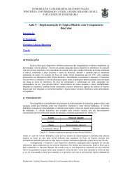
Component values are indicated in Figure 3. The explanation<br />
for the choices in component values follows.<br />
First calculate the maximum duty cycle, d(max). To calculate<br />
this assume that at maximum load/minimum line<br />
conditions, the converter will be at the continuous conduction<br />
boundary and there will be no idle time after the<br />
inductors are discharged. For all other load/line conditions,<br />
the UCC3890 will stretch the off time, to create an<br />
idle time after the inductors are discharged, in order to<br />
UCC1890<br />
UCC2890<br />
UCC3890<br />
maintain a constant output voltage. For a single flyback<br />
stage at continuous conduction boundary<br />
1<br />
d =<br />
1 + VIN<br />
VOUT<br />
For the cascaded flyback stages of the UCC3890 topology,<br />
the corresponding equation is<br />
d(max) =<br />
in this case<br />
1<br />
1 + √⎺⎺⎺ VIN<br />
VOUT′<br />
1<br />
d(max) =<br />
1 + √⎺⎺⎺ 100V<br />
2V<br />
= 0.125<br />
Next using the operating frequency and the maximum<br />
duty cycle to calculate the maximum on time<br />
TON(max) = d(max)<br />
FSWITCHING<br />
in this case<br />
TON(max) = 0.125<br />
= 1.25μs<br />
100kHz<br />
correspondingly<br />
TOFF(min) =<br />
Figure 3. Example Application<br />
5<br />
1 − 0.125<br />
100kHz<br />
= 8.75μs<br />
UDG-96056