Create successful ePaper yourself
Turn your PDF publications into a flip-book with our unique Google optimized e-Paper software.
PIN DESCRIPTIONS<br />
CS: The high side of the current sense shunt is connected<br />
to this pin. Short CS to VDD for voltage feedback<br />
operation.<br />
CT: Oscillator timing capacitor is connected to this pin.<br />
DRIVE: Gate drive to external power switch.<br />
FB: Output of current sense amplifier. This pin can be<br />
used for direct output voltage feedback if the current<br />
sense amp input pin CS is shorted to the VDD pin.<br />
GND: Ground pin.<br />
APPLICATION INFORMATION<br />
OPERATION (VOLTAGE OUTPUT)<br />
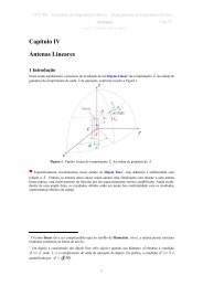
Figure 1 shows a typical voltage mode application.<br />
When input voltage is first applied, all of the current<br />
through RDD and 80% of the current through RON,<br />
charge the external capacitor C3 connected to VDD. As<br />
the voltage builds on VDD, undervoltage lockout holds<br />
the circuit off and the output DRIVE low until VDD<br />
reaches 8.4V. At this time, DRIVE goes high, turning on<br />
the external power switch Q1, and 15% of the current<br />
into TON is directed to the timing capacitor CT. The voltage<br />
at TON is fixed at approximately 11V, so CT<br />
charges to a fixed threshold with current<br />
VIN – 11V<br />
I = 0.2 •<br />
RON<br />
Since the input line is much greater than 11V, the<br />
charge current is approximately proportional to the input<br />
line voltage. DRIVE is only high while CT is charging, so<br />
Figure 1. Typical Voltage Mode Application<br />
3<br />
UCC1890<br />
UCC2890<br />
UCC3890<br />
TOFF: Resistor ROFF connects from voltage output to<br />
this pin to provide a maximum capacitor discharge current<br />
proportional to output voltage.<br />
TON: Resistor RON connects from line input to this pin to<br />
provide capacitor charge current proportional to line voltage.<br />
The current in RON also provides power for the 9V<br />
shunt regulator at VDD.<br />
VDD: Output of 9V shunt regulator.<br />
UDG-96053<br />
the power switch on time is inversely proportional to line<br />
voltage. This provides a constant line voltage-switch on<br />
time product.<br />
At the end of the switch on time, Q1 is turned off, and<br />
the 15% of the RON current which was charging CT is<br />
diverted to ground. The power switch off time is controlled<br />
by discharge of CT, which is determined by the outut<br />
voltage as described here:<br />
UDG-96054