You also want an ePaper? Increase the reach of your titles
YUMPU automatically turns print PDFs into web optimized ePapers that Google loves.
ABSOLUTE MAXIMUM RATINGS<br />
IDD . . . . . . . . . . . . . . . . . . . . . . . . . . . . . . . . . . . . . . . . . . 7.5mA<br />
Current into TON . . . . . . . . . . . . . . . . . . . . . . . . . . . . . . . 7.5mA<br />
Voltage on VOUT . . . . . . . . . . . . . . . . . . . . . . . . . . . . . . . . . . . . . . . . . . . 20V<br />
Current into TOFF . . . . . . . . . . . . . . . . . . . . . . . . . . . . . . 250μA<br />
Storage Temperature . . . . . . . . . . . . . . . . . . . –65°C to +150°C<br />
Junction Temperature . . . . . . . . . . . . . . . . . . –55°C to +150°C<br />
Lead Temperature (Soldering, 10 sec.) . . . . . . . . . . . . . +300°C<br />
Currents are positive into, negative out of the specified terminal.<br />
Consult Packaging Section of Databook for thermal limitations<br />
and considerations of packages.<br />
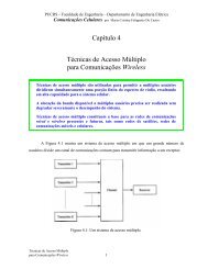
CONNECTION DIAGRAMS<br />
DIL-8, SOIC-8 (Top View)<br />
J, N, or D Packages<br />
ELECTRICAL CHARACTERISTICS: Unless otherwise stated, these specifications apply for TA = –55°C to 125°C for<br />
UCC1890, –40°C to 85°C for the UCC2890, and 0°C to 70°C for the UCC3890. No load at DRIVE pin (CLOAD = 0), TA = TJ.<br />
UCC1890<br />
UCC2890<br />
UCC3890<br />
PARAMETER TEST CONDITIONS MIN TYP MAX UNITS<br />
General<br />
VDD Zener Voltage ITON = 4.75mA 8.7 9.0 9.3 V<br />
Operating Current ITON<br />
Undervoltage Lockout<br />
IDD = –1mA, F = 150kHz 2 mA<br />
Minimum Voltage to Start 8.0 8.4 8.9 V<br />
Minimum Voltage after Start 5.8 6.2 6.6 V<br />
Hysteresis<br />
Oscillator<br />
1.8 V<br />
Amplitude ITON = 3mA; ITOFF = 50μA; VFB = 0V CT = 100pF 3.1 3.4 3.7 V<br />
CT to DRIVE High Delay Overdrive = 200mV 100 200 ns<br />
CT to DRIVE Low Delay Overdrive = 200mV 50 100 ns<br />
Charge Coefficient ICT/ITON ITON = 3mA; VCT = 3.0V 0.135 0.15 0.165 μA/μA<br />
Discharge Coefficent ICT/ITOFF<br />
Driver<br />
ITOFF = 50μA; VCT = 3.0V 0.95 1.00 1.05 μA/μA<br />
VOL I = 100mA (Note 1) 0.7 1.8 V<br />
VOH I = –100mA referred to VDD (Note 1) –2.9 –1.2 V<br />
Rise Time CL = 1nF 35 70 ns<br />
Fall Time<br />
<strong>Line</strong> Voltage Detection<br />
CL = 1nF 30 60 ns<br />
Minimum ITON for Fault 1.0 1.5 2.0 mA<br />
ITON Detector Hysteresis 80 μA<br />
On Time During Fault<br />
VOUT Error Amplifier<br />
2 μs<br />
Reference Level ITOFF = 50μA, ICT = 25μA 1.20 1.25 1.30 V<br />
Voltage at TOFF ITOFF = 50μA 0.3 0.4 0.5 V<br />
Regulation gm<br />
Current Sense Amplifier<br />
ITOFF = 50μA (Note 2) 2.25 4.5 6.75 mA/V<br />
Gain VCS = 90 – 110mV 11.8 12.5 13.0 V/V<br />
Input <strong>Off</strong>set Voltage VCS = 90 – 110mV –5 0 5 mV<br />
Input Voltage for CS Amplifier Enabled ITON = 3mA, Referred to VDD –1.5 –0.8 V<br />
Input Voltage for CS Amplifier Disabled ITON = 3mA, Referred to VDD –0.8 –0.3 V<br />
CS Amplifier Source Impedance 5 10 15 kΩ<br />
Note 1: VDD forced to 100mV below VDD Zener Voltage<br />
Note 2: gm is defined as ΔICT<br />
for the values of VFB where the error amp is in regulation. The two points used to calculate gm<br />
ΔVFB<br />
are for ICT at 65% amd 35% of its maximum value.<br />
2