

UltraVoice Manual - Alerting & Notification
UltraVoice Manual - Alerting & Notification
UltraVoice Manual - Alerting & Notification

Create successful ePaper yourself
Turn your PDF publications into a flip-book with our unique Google optimized e-Paper software.
Speaker Wiring for DSA Series Sirens<br />
DSA speaker arrays range in size from<br />
200 Watts to 600 Watts. The<br />
<strong>UltraVoice</strong>+ controller may drive multiple<br />
combinations of DSA speakers up to<br />
3200 watts of power. Each<br />
ULTRAVOICE amplifier is designed to<br />
drive an 11 ohm impedance which<br />
corresponds to two series pairs of DSA<br />
speakers wired in parallel (400 Watts).<br />
Because virtually any combination of<br />
DSA arrays may be used with an<br />
<strong>UltraVoice</strong>+ controller, all possible wiring<br />
Federal Signal <strong>UltraVoice</strong><br />
Installation and Operation <strong>Manual</strong><br />
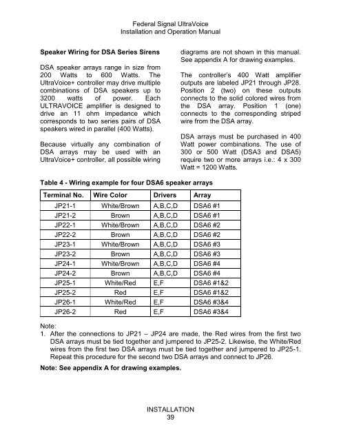
Table 4 - Wiring example for four DSA6 speaker arrays<br />
Terminal No. Wire Color Drivers Array<br />
JP21-1 White/Brown A,B,C,D DSA6 #1<br />
JP21-2 Brown A,B,C,D DSA6 #1<br />
JP22-1 White/Brown A,B,C,D DSA6 #2<br />
JP22-2 Brown A,B,C,D DSA6 #2<br />
JP23-1 White/Brown A,B,C,D DSA6 #3<br />
JP23-2 Brown A,B,C,D DSA6 #3<br />
JP24-1 White/Brown A,B,C,D DSA6 #4<br />
JP24-2 Brown A,B,C,D DSA6 #4<br />
JP25-1 White/Red E,F DSA6 #1&2<br />
JP25-2 Red E,F DSA6 #1&2<br />
JP26-1 White/Red E,F DSA6 #3&4<br />
JP26-2 Red E,F DSA6 #3&4<br />
INSTALLATION<br />
39<br />
diagrams are not shown in this manual.<br />
See appendix A for drawing examples.<br />
The controller‟s 400 Watt amplifier<br />
outputs are labeled JP21 through JP28.<br />
Position 2 (two) on these outputs<br />
connects to the solid colored wires from<br />
the DSA array. Position 1 (one)<br />
connects to the corresponding striped<br />
wire from the DSA array.<br />
DSA arrays must be purchased in 400<br />
Watt power combinations. The use of<br />
300 or 500 Watt (DSA3 and DSA5)<br />
require two or more arrays i.e.: 4 x 300<br />
Watt = 1200 Watts.<br />
Note:<br />
1. After the connections to JP21 – JP24 are made, the Red wires from the first two<br />
DSA arrays must be tied together and jumpered to JP25-2. Likewise, the White/Red<br />
wires from the first two DSA arrays must be tied together and jumpered to JP25-1.<br />
Repeat this procedure for the second two DSA arrays and connect to JP26.<br />
Note: See appendix A for drawing examples.


