
You also want an ePaper? Increase the reach of your titles
YUMPU automatically turns print PDFs into web optimized ePapers that Google loves.
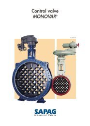
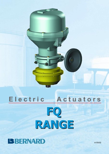
Electric Actuators<br />
A105/02
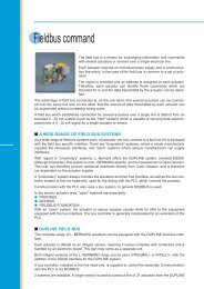
"THE" fail safe electric actuator<br />
For all quarter turn applications, Spring Return<br />
<strong>FQ</strong> <strong>range</strong> Actuators ensure automatic opening<br />
or closing even without any power supply.<br />
■ APPLICATION FIELDS<br />
They include :<br />
● All those where the loss of power supply<br />
necessitates automatically to put the driven<br />
device in a safety position.<br />
● All those where the risks are such, that driving<br />
the device to its safety position must<br />
be possible at any time even in the absence<br />
of power supply.<br />
For example : Storage and distribution of gas<br />
and dangerous fluids, fire protection systems,<br />
chemical installation safety, climate control<br />
and ventilation of hazardous areas (protection<br />
of the environment).<br />
■ IMPORTANT FUNCTIONS<br />
When energized (after electrical wiring) the<br />
actuator operates the valve normally and at<br />
the same time compresses the spring which is<br />
held in the loaded position by the solenoid<br />
brake. In case of power failure to the solenoid,<br />
the spring will drive the actuator and valve to<br />
the safety position either open or closed. The<br />
associated dashpot speed controls the spring<br />
action and permits a safe and shock-free operation<br />
of the valve. When the power supply is<br />
restored (no resetting of the spring is<br />
required), the actuator is immediately available<br />
for normal operation.<br />
In standard, the spring operates clockwise<br />
when viewed from the top. The electric part is<br />
equipped with an asynchrone triphase motor<br />
of squirrel cage type. Other versions are possible<br />
in single phase and direct current supply.<br />
What is FAIL SAFE ?<br />
In addition to their normal function of on-off or<br />
modulating actuators, <strong>FQ</strong> operators are<br />
designed in order to immediately close or<br />
open the driven device, thanks to the action<br />
of an integrated spring, and without any<br />
external power source, whenever they detect<br />
an emergency such as :<br />
■ A loss of signal,<br />
■ An abnormal temperature,<br />
■ Or the loss of power itself.<br />
■ STANDARD DESIGN<br />
● Mechanical position indicator<br />
● Travel limit switch setting is easy, with a<br />
simple screw driver<br />
● Adjustable mechanical stops for quarter<br />
turn<br />
● Electrical connection to a terminal strip.<br />
■ ENCLOSURES<br />
Bernard actuators are weather-proof to IP67<br />
and are also available explosion-proof according<br />
to European Standards EN 50014 - EN<br />
50018, class EEx dIIC T4, T5, T6, approval N°<br />
INERIS 93C5017.<br />
● Catalogue options :<br />
■ MOTOR :<br />
- 3PH 50 or 60 HZ<br />
- 1PH 50 or 60 HZ<br />
- DC - versions<br />
■ ON-OFF or Modulating duty<br />
■ Extra limit switches<br />
■ Anticondensation heater resistance<br />
■ Position transmitters 4-20mA or<br />
Potentiometer<br />
L. BERNARD 4 rue d'arsonval - BP 91 - 95505 GONESSE. France<br />
Tel. +33.1.34.07.71.00 - Fax +33.1.34.07.71.01<br />
E-mail : mail@bernard-actuators.com - Internet . http://www.bernard-actuators.com
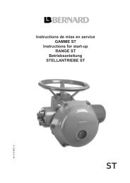
Dimensional drawings<br />
■ <strong>FQ</strong>04 & <strong>FQ</strong>08<br />
796<br />
stop screws<br />
90˚ +/- 2˚<br />
"Closed" position<br />
position<br />
indicator<br />
connection<br />
4 x M8 depth 14 = F07<br />
square C<br />
2 x 45˚<br />
depth h<br />
Type A Ø B Square C h Weight<br />
<strong>FQ</strong>04 389 Ø 84 17 19 25 kg<br />
<strong>FQ</strong>08 400 Ø 117 22 24 30 kg<br />
■ <strong>FQ</strong>30<br />
451<br />
position<br />
indicator<br />
101<br />
Ø290<br />
90˚ 0˚<br />
"Open" position<br />
connection<br />
lockable<br />
handwheel<br />
clutch<br />
weight<br />
100 kg<br />
4 x M16 depth 25 = F14<br />
2<br />
A<br />
Ø100 f8<br />
Ø140<br />
Ø175<br />
74<br />
4<br />
■ <strong>FQ</strong>12 & <strong>FQ</strong>18<br />
A<br />
B<br />
lockable<br />
handwheel<br />
clutch<br />
753<br />
101<br />
410<br />
D<br />
Position<br />
indicator<br />
90˚<br />
Ø C<br />
"Closed" position<br />
Ø290<br />
Ø394<br />
0˚<br />
connection<br />
stop screws<br />
90˚ +/- 2˚<br />
4 x M depth: 20<br />
2<br />
Square E<br />
Ø F<br />
Type A B Ø C D Square E Ø F M Weight<br />
<strong>FQ</strong>12 502 167 Ø125 25 22 Ø102 M10 40 kg<br />
<strong>FQ</strong>18 521 185 Ø130 31 25 Ø78 M12 45 kg<br />
■ <strong>FQ</strong>50<br />
position<br />
indicator<br />
lockable<br />
handwheel<br />
clutch<br />
"Open" position<br />
connection<br />
weight<br />
120 kg<br />
4 x M16 depth 25 = F14<br />
Ø100 f8<br />
Ø140<br />
Ø175<br />
A 4 74
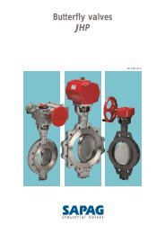
Standard mounting<br />
<strong>FQ</strong>04<br />
<strong>FQ</strong>08<br />
<strong>FQ</strong>12<br />
<strong>FQ</strong>18<br />
<strong>FQ</strong>30 & <strong>FQ</strong>50<br />
4 x M8 = F07<br />
60<br />
4 x M8 = F07<br />
60<br />
Ø102<br />
Ø102<br />
4 x M16 depth 25 = F14<br />
2<br />
45˚<br />
45˚<br />
Ø55<br />
Ø55<br />
40<br />
40<br />
Ø70<br />
Ø70<br />
Ø70 80<br />
40<br />
4 x M10 = F10<br />
Ø70 80<br />
Ø100 f8<br />
Ø140<br />
Ø175<br />
40<br />
4 x M10 = F10<br />
74<br />
4<br />
Parallel square Key Flat<br />
S<br />
d7<br />
S Ød7 S<br />
11 / 14 / 17 14 / 18 / 22 / 28<br />
11 / 14 / 17<br />
14 / 18 / 22 / 28<br />
18 / 22 / 28 / 36<br />
18 / 22 / 28 / 36<br />
19 / 22 / 36 22 / 28 / 30 / 40 19 / 22 / 36<br />
S<br />
11 / 14 / 17<br />
S Ød7 S<br />
11 / 14 / 17<br />
S Ød7 S<br />
14 / 17 / 19 / 22<br />
14 / 17 / 19 / 22<br />
14 / 17 / 19 / 22<br />
S Ød7 S<br />
14 / 17 / 19 / 22<br />
S Ød7 S
Performances<br />
On / Off<br />
Max. Type Operating time 90°/sec Handwheel Motor S4 -Duty : 30%<br />
Torque Motor Spring P Speed In Id Cos E (1)<br />
On / Off<br />
Nm Standard Slow Kw rpm A A ϕ %<br />
40 <strong>FQ</strong>04 33 ± 3 ± 7 No 0,03 3000 0,5 0,7 0,9 25%<br />
80 <strong>FQ</strong>08 33 ± 2 ± 6 No 0,03 3000 0,5 0,7 0,9 25%<br />
120 <strong>FQ</strong>12 93 ± 2 ± 10 Yes 0,03 3000 0,5 0,7 0,9 25%<br />
180 <strong>FQ</strong>18 93 ± 3 ± 15 Yes 0,03 3000 0,5 0,7 0,9 25%<br />
300 <strong>FQ</strong>30 117 ± 7 ± 18 Yes 0,03 3000 0,5 0,7 0,9 25%<br />
Max. Type Operating time 90°/sec Handwheel Motor S4 -Duty : 30%<br />
Torque Motor Spring P Speed In Id Cos E (1)<br />
On / Off.<br />
Nm Standard Slow Kw rpm A A ϕ %<br />
40 <strong>FQ</strong>04 28 ± 3 ± 7 No 0,03 3600 1,0 1,5 0,9 30%<br />
80 <strong>FQ</strong>08 28 ± 2 ± 6 No 0,03 3600 1,0 1,5 0,9 30%<br />
120 <strong>FQ</strong>12 78 ± 2 ± 10 Yes 0,03 3600 1,0 1,5 0,9 30%<br />
180 <strong>FQ</strong>18 78 ± 3 ± 15 Yes 0,03 3600 1,0 1,5 0,9 30%<br />
300 <strong>FQ</strong>30 98 ± 7 ± 18 Yes 0,03 3600 1,0 1,5 0,9 30%<br />
(1) = Efficiency<br />
3 PH 400 V 50 Hz<br />
Max. Type Operating time 90°/sec Handwheel Motor S4 -Duty : 30%<br />
Torque Motor Spring P Speed In Id Cos E (1)<br />
Nm Standard Slow Kw rpm A A ϕ %<br />
40 <strong>FQ</strong>04 14 ± 3 ± 7 No 0,06 3000 0,3 0,9 0,8 43%<br />
40 <strong>FQ</strong>04 33 ± 3 ± 7 No 0,06 3000 0,3 0,9 0,8 43%<br />
80 <strong>FQ</strong>08 33 ± 2 ± 6 No 0,06 3000 0,3 0,9 0,8 43%<br />
120 <strong>FQ</strong>12 39 ± 2 ± 10 Yes 0,06 3000 0,3 0,9 0,8 43%<br />
120 <strong>FQ</strong>12 93 ± 2 ± 10 Yes 0,06 3000 0,3 0,9 0,8 43%<br />
180 <strong>FQ</strong>18 93 ± 3 ± 15 Yes 0,06 3000 0,3 0,9 0,8 43%<br />
300 <strong>FQ</strong>30 117 ± 7 ± 18 Yes 0,06 3000 0,3 0,9 0,8 43%<br />
500 <strong>FQ</strong>50 117 ± 9 ± 27 Yes 0,06 3000 0,3 0,9 0,8 43%<br />
REMARKS :<br />
1 PH 230 V 50 Hz<br />
1 PH 115 V 60 Hz<br />
■ The operating time with the spring can increase according to the load. The mentioned operating times refers to the max<br />
output torque.<br />
■ The solenoid rated power is 21 W. This solenoid is normally under permanent power supply.
S30000 standard wiring diagram