Group 1
Group 1
Group 1

You also want an ePaper? Increase the reach of your titles
YUMPU automatically turns print PDFs into web optimized ePapers that Google loves.
Informal Task of the System<br />
Faculty of Engineering – Department of Computer Science<br />
Software Engineering – Prof. Dr. M. Heisel<br />
Embedded Systems Solution of Lab – <strong>Group</strong> 01<br />
Phase 1<br />
An Automatic Cruise Control System (CCS) for a car should be developed using the<br />
embedded system development process presented in the lecture. The standard car<br />
is equipped with an anti-lock braking system (ABS) that has an additional digital<br />
input to activate the brakes. The digital input is realized by a serial (RS-232)<br />
connection with 9600 Baud, odd parity, and one stop bit. Values between “0” and<br />
“255” can be sent to the ABS. When “255” is sent to the ABS, the car brakes as<br />
strongly as possible. When “0” is sent to the ABS, the brakes are released<br />
completely. All actions of the driver are sent to the CAN-Bus. The position of the<br />
Accelerator pedal is represented by a CAN-Message with Event-ID 101 and one byte<br />
data (0=no Acceleration, 255=maximal Acceleration). The position of the brake pedal<br />
is represented by a CAN-Message with Event-ID 102 and one byte data (0=no<br />
braking, 255=maximum braking power). The Event-ID for the speed in km/h is 312<br />
with 2 data bytes containing the speed in integer format.<br />
Driving the car should become more convenient. It should be possible to set the<br />
current speed as a desired speed. The car should drive with the desired speed until<br />
the driver brakes or the speed is one minute above the desired speed. The speed<br />
should be automatically decreased when the car ahead (or another object) is within a<br />
certain distance According to the current speed. The car should accelerate up to the<br />
desired speed when the distance is big enough. The CCS should brake with at most<br />
30 % of the maximum braking power. It should also be possible to resume to the last<br />
default speed after breaking. The driver should be able to activate and deactivate the<br />
CCS. The driver should be able to increase and decrease the desired speed in steps<br />
of 10 km/h. The system in use connects the Acceleration pedal with the motor by a<br />
bowden wire. The bowden wire can be replaced by an actuator that sets the<br />
Acceleration according to the value of a CAN message with one byte data (0=no<br />
Acceleration, 255=maximal Acceleration). It can be set via Event-ID 105. If no<br />
Events with ID 105 are received for 100 ms the values sent via Event-ID 101 are<br />
used.<br />
We can add an electronic switch with the buttons “+”, “-”, “Set”, “Resume”, and “Off”<br />
to the car. The electronic switch sends CAN-Events with the Event-IDs 501 (“+”), 502<br />
(“-”), 503 (“Set”), 504 (“Resume”), and 505 (“Off”) when the buttons are pressed. An<br />
acoustical and optical warning can be generated by sending a CAN message with<br />
the Event-ID 601.<br />
We can also buy a radar sensor that measure the distance to an object in front of the<br />
car. It sends the distance via CAN every 25 ms. The Event-ID reserved for the radar<br />
sensor is 820. The CAN-Message contains two bytes data representing the distance<br />
in cm (0 = 0 cm, 65534 = 655.34 m). When the sensor is not usable (e.g., dirty,<br />
measures an incoming car) a value of 65535 is sent. A broken sensor can be<br />
detected by missing CAN-Messages for 100 ms.<br />
Page 1
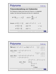
1.1. Context Diagram<br />
a. {pressBrake, releaseBrake}<br />
b. {pressAccel, releaseAccel}<br />
c. {sendBrakeSignal}<br />
d. {sendIincreaseSpeedSignal}<br />
e. {engineControlUsingBowdenWire}<br />
1.2. Shortcomings<br />
f. {brakeControlUsingBowdenWire}<br />
g. {increaseSpeed, decreaseSpeed}<br />
h. {sendBrakeSignal}<br />
i. {controlBrake, brakeStatusSignal}<br />
SC1: Engine cannot automatically stop (decreaseSpeed immediately) when it is very<br />
close to another car ahead of it.<br />
SC2: Engine cannot increaseSpeed automatically with the desired speed or default<br />
speed when there is distance big enough ahead of it after braking.<br />
SC3: The system can not measure the distance to an object in front of the car.<br />
SC4: The Driver must drive fully concentrate to preserve the desired speed and safe.<br />
1.3. Facts<br />
F1: The standard car is equipped with an anti-lock braking system (ABS) that has<br />
an additional digital input to activate the Brakes. The ABS digital input is<br />
realized by a serial (RS-232) connection with 9600 Baud, odd parity, and one<br />
stop bit. Values between “0” and “255” readMsgforBrake. When Driver<br />
pressBrake and then BrakePedal send brakeSignal “255” to the ABS, the car<br />
brakes as strongly as possible. Otherwise when Driver releaseBrake,<br />
furthermore send brakeSignal “0” will send to the ABS, and the Brakes are<br />
released completely.<br />
F2: Controller-area network (CAN or CAN-Bus) is a vehicle bus standard designed<br />
to allow microcontrollers and devices to communicate with each other within a<br />
vehicle without a host computer<br />
Page 2
F3: All actions of the Driver are sent to the CAN-Bus.<br />
F4: The position of the AccelPedal when accelSignal is represented by a CAN-Bus<br />
with readCANMsg Event-ID 101 and one byte data (0=no Acceleration,<br />
255=maximal Acceleration). The AccelPedal will send accelSignal as an input<br />
signal to the CAN-Bus.<br />
F5: The position of the BrakePedal when brakeSignal is represented by a CAN-Bus<br />
with readCANMsg Event-ID 102 and one byte data (0=no braking,<br />
255=maximum braking power).<br />
F6: The CAN-Bus Event-ID for readCANMsgSpeed in km/h is 312 with 2 data bytes<br />
containing the speedValue in integer format.<br />
F7: The System also connects AccelPedal to the Engine and BrakePedal to the<br />
ABS by Actuator.<br />
F8: The driver are able to increase speed when pressAccel the AccelPedal and<br />
decrease speed when releaseAccel.<br />
F9: The driver are also able to decrease speed when pressBrake the BrakePedal<br />
F10: Anti Lock Braking System (ABS) is a safety system for gripBrake and<br />
releaseBrake to prevents the wheels from locking while braking.<br />
F11: The car cannot stop immediately.<br />
F12: Radar as a Sensor sends the distanceValue by writeCANMsg every 25ms.<br />
F13: The closest distanceValue to the to front object using acc is 50 meter, if in this<br />
distance if the current speed is below 30 km/hour then acc will be deactivated.<br />
1.4. Assumptions<br />
A1: The Driver is not drunk and drives the car fully concentrates to maintain the<br />
desired speed.<br />
A2: The Driver knows how to use and control all car equipments.<br />
A3: Both the AccelPedal and the BrakePedal are not being pressed by the driver at<br />
the same time.<br />
1.5. Glossary<br />
Driver: A person who is in charge of controlling the vehicle<br />
Accel_Pedal: A pedal that give impulse to the machine to increase the power of the<br />
engine<br />
Brake_Pedal: A pedal that is used to decrease the speed of the vehicle<br />
Engine:Engine that creates the movement of a vehicle<br />
Brake: Plates that are placed in the wheels to decrease the speed of the wheels<br />
ABS: Anti Lock Braking System is a safety system on motor vehicles which<br />
prevents the wheels from locking while braking.<br />
ACC Control Unit: Panel to control the ACC.<br />
Multifunctional Display: The Display to show the ACC speed and the ACC State<br />
ACC Speed: Lexical domain to get the current speed.<br />
ACC State: Lexical domain to get the ACC state.<br />
CAN-Bus: Controller-area network (CAN or CAN-bus) is a vehicle bus standard<br />
designed to allow microcontrollers and devices to communicate with each<br />
other within a vehicle without a host computer.<br />
Page 3
Bowden Wire: A bowden wire is a type of flexible cable used to transmit mechanical<br />
force or energy by the movement of an inner cable (most commonly of steel<br />
or stainless steel) relative to a hollow outer cable housing. The housing is<br />
generally of composite construction, consisting of a helicalsteel wire, often<br />
coated with plastic, and with a plastic outer sheath.<br />
1.6. Alternatives<br />
ALT1: Hire a professional driver<br />
ALT2: Use GPS and combine with RADAR system.<br />
ALT3: Create an Automatic Cruise Control System that can do automation to drive a<br />
car more comfortable but safe.<br />
1.7. Validations I<br />
Driver<br />
Accel_Pedal<br />
Brake_Pedal<br />
Engine<br />
Brake<br />
ABS<br />
CAN-Bus Controller<br />
pressBrake<br />
sendBrakeSignalreleaseBrake<br />
pressAccel<br />
releaseAccel<br />
sendBrakeSignal<br />
sendIncreaseSpeedSignal<br />
engineControlUsingBowden<br />
Wire<br />
brakeControlUsingBowdenW<br />
ire<br />
decreaseSpeed<br />
sendBrakeSignalincreaseSpe<br />
ed<br />
controlBrake<br />
brakeStatusSignal<br />
1.8. Validations II<br />
F1 F2 F3 F4 F5 F6 F7 F8 F9 F10 A1 A2 A3<br />
DOMAIN<br />
PHENOMENA<br />
The context diagram contains all domains necessary to describe the shortcomings<br />
and the shortcomings are stated using elements of the domain knowledge<br />
description.<br />
SC1: Engine<br />
SC2: Engine, braking.<br />
SC4: Driver<br />
Page 4
2.1 System Mission<br />
Phase 2<br />
SM1: The system should make the driving more convenience.<br />
SM2: The system should make driving of the car safer.<br />
2.2 Select development alternative<br />
ALT1: Hire a professional driver<br />
Driver is also a human, still possible to makes mistake when he is not concentrate.<br />
ALT2: Use GPS and combine with RADAR system.<br />
Socket Bluetooth GPS: Around 300 Euro and RADAR system around 200 Euro.<br />
This alternative is quite cheap but only covers SC3.<br />
ALT3: Create an Automatic Cruise Control (CCS) System that can do automation to<br />
drive a car more comfortable but safe.<br />
CCS prices only 300 Euro. If CCS combined with RADAR system it’s equal to 500<br />
Euro. With the same price as ALT2 this system has more advantages (cover SC1,<br />
SC2, SC3, SC4).<br />
Therefore, ALT3 has chosen as development alternative.<br />
2.3 New Context Diagram<br />
Page 5
a: {press accel, release accel}<br />
b: {press break, release brake}<br />
c: {press button plus, press button minus, press button set, press button resume, press<br />
button off}<br />
d: {accel signal}<br />
e: {button signal}<br />
f: {brake signal}<br />
g: {speed value, ACC state}<br />
h: {distance value}<br />
i: {readCANMsg, writeCANMsg}<br />
j: {read CANMsgSpeed}<br />
k: {set speed, release speed}<br />
l; {readMsgforBrake}<br />
m: {grip brake, release brake}<br />
2.4 Changed/added/removed Facts<br />
No Changed/added/removed Facts<br />
2.5 Changed/added/removed Assumptions<br />
No Changed/added/removed Assumptions<br />
2.6 Changed Glossary<br />
CCS: Cruise Control System is a system that automatically controls the rate of<br />
motion of a motor vehicle. The driver sets the speed and the system will take<br />
over the throttle of the car to maintain the same speed.<br />
2.7 Initial Requirements<br />
R1: The driver pressButtonResume then the ACC is activated.<br />
R2: The driver pressButtonOff then the ACC is deactivated.<br />
R3: If driver pressButtonSet then, the car current speed is setSpeed as desired<br />
speed.<br />
R4: If the driver pressButtonPlus then the desired speed will be increased in the<br />
step of 10km/hour.<br />
R5: If the driver pressButtonMinus then the desired speed will be decreased in<br />
the step of 10km/hour<br />
R6: If the ACC is activated and the speed is set and sensor detect there is an<br />
object in front of the car for certain distanceValue then the speed will be<br />
automatically decreased.<br />
R7: If the ACC is activated and sensor detect from distanceValue there is no<br />
object in front of the car then the ACC can accelerate the car to the desired<br />
speed.<br />
R8: If the ACC is activated it can only brake the car with readMessageforBrake<br />
at most 30% of maximum braking power.<br />
R9: If the ACC is activated, ACC can resume to the last default setSpeed after<br />
braking.<br />
R10: The Actuator will setSpeed using signal id 105, but if there is no signal 105<br />
for 100ms then signal 101 will be used.<br />
Page 6
R11: If there are any buttonSignal then there will be an acoustic and optical<br />
warning from multifunctional display.<br />
R12: All accState will also can be seen in multifunctional display.<br />
R13: If there are accelSignal or brakeSignal from the driver when the ACC is<br />
activated then the ACC will be overridden.<br />
Consolidate Requirements<br />
SM1: The system should make the driving more convenience.<br />
Driving will be more convenience when the Driver can easily control the car in<br />
all possible cases. It should be possible to set the current speed as a desired<br />
speed. The car should drive with the desired speed until the driver brakes or<br />
the speed is one minute above the desired speed. The car should accelerate<br />
up to the desired speed when the distance is big enough and decrease Speed<br />
if the speed is lower than the desired speed and the distance are close<br />
enough. It should also be possible to resume to the last default speed after<br />
breaking.<br />
Necessary:<br />
(R1, R2, R3, R4, R5, R6, R8, R9)<br />
• Sufficient :<br />
(R1 ٨ R2 ٨ R3 ٨ R4 ٨ R5 ٨ R6 ٨ R9 ٨ F2 ٨ F3 ٨ F4 ٨ F5 ٨ F6 ٨ F8 ٨ F9 ٨<br />
A2) ٨<br />
(R8 ٨ R9 ٨ F2 ٨ F3 ٨ F4 ٨ F5 ٨ F6 ٨ A2 ٨ A3) ٨ (R5 ٨ F9 ٨ F10 ٨ A2 ٨ A3)<br />
<br />
SM1<br />
SM2: The system should make driving of the car safer.<br />
Driving will be safer when the system can easily detects an object in front of<br />
the car. The speed should be automatically decreased when the car ahead (or<br />
another object) is within a certain distance according to the current speed. In<br />
case the system fails, the engine is remotely controlled by actuators which<br />
connect the acceleration pedal with the engine.<br />
٨<br />
Summary:<br />
• Necessary :<br />
(R6, R7, R8)<br />
• Sufficient :<br />
(R6 ٨ R7 ٨ F1 ٨ F2 ٨ F3 ٨ F5 ٨ F6 ٨ F7 ٨ F9 ٨ A2 ٨ A3) ٨ (R8 ٨ F1 ٨ F2 ٨ F3<br />
A3) SM2<br />
R’ = {R1, R2, R3, R4, R5, R6, R7, R8, R9, R10, R11, R12, R13} (mission critical<br />
requirements)<br />
Requirements R1, R2, R3, R4, R5, R6, R7, R8, R9, R10, R11, R12 and R13 are<br />
“need to have”<br />
All requirements will be implemented.<br />
Page 7
2.8 Validation<br />
2.8.1. Validation I<br />
• The applied operators for the context diagram are given directly below the<br />
diagram.<br />
• The system mission statement addresses the shortcomings or refer to domain<br />
knowledge of the system in use:<br />
SM1 address shortcomings SC2 and SC4<br />
SM2 address shortcomings SC1 and SC3<br />
• The phenomena and the domains of the context diagram are printed<br />
emphasized in the requirements and in the domain knowledge.<br />
2.8.2 Validation II<br />
All given and designed domains are referenced in the requirements and the<br />
domain knowledge:<br />
Driver<br />
Table1 All given, design domains & phenomenon referenced to the<br />
Requirement<br />
ACC Control Unit<br />
Accel_Pedal<br />
Brake_Pedal<br />
CAN-Bus Controller<br />
Multifuntional Display<br />
Sensor<br />
Actuator<br />
Engine<br />
ABS<br />
Brake<br />
pressButtonResume<br />
pressButtonOff<br />
pressButtonSet<br />
setSpeed<br />
pressButtonPlus<br />
pressButtonMinus<br />
distanceValue<br />
R1 R2 R3 R4 R5 R6 R7 R8 R9 R10 R1<br />
1<br />
DOMAIN<br />
PHENOMENA<br />
R1<br />
2<br />
R1<br />
3<br />
Page 8
Driver<br />
readMessageforBrake<br />
buttonSignal<br />
accState<br />
Accel_Pedal<br />
Brake_Pedal<br />
CAN-Bus<br />
Sensor<br />
Actuator<br />
Engine<br />
ABS<br />
Brake<br />
pressBrake<br />
releaseBrake<br />
brakeSignal<br />
accelSignal<br />
accelSignal<br />
brakeSignal<br />
Table2 All domains & phenomenas referenced to the fack and Assumption<br />
readCANMsgSpeed<br />
readCANMsg<br />
speedValue<br />
pressAccel<br />
releaseAccel<br />
readMsgforBrake<br />
gripBrake<br />
releaseBrake<br />
distanceValue<br />
writeCANMsg<br />
F1 F2 F3 F4 F5 F6 F7 F8 F9 F10 F1<br />
1<br />
DOMAIN<br />
PHENOMENA<br />
F1<br />
2<br />
F1<br />
3<br />
A1 A2 A3<br />
Page 9
3.1. Problem diagrams.<br />
Phase 3<br />
3.1.1. Problem diagram 1: ACC Control State.<br />
a. ACC State Control!{setDesiredSpeed, increaseDesiredSpeed,<br />
decreaseDesiredSpeed }<br />
b. CAN Bus! {sendSignal +, -, resume, set, off}<br />
c. ACC Control Unit! {press +, - , resume, set, off}<br />
d. Driver! {press +, - , resume, set, off }<br />
e. {get value}<br />
f. {setDesiredSpeed}<br />
3.1.2. Problem diagram 2: IncreaseDecrease Control – ACC<br />
Page 10
a. IDC - ACC!{sendDistanceSignal}s<br />
b. AutoIDS- CCS!{changeDesiredSpeed}<br />
c. SS!{sendCurrentSpeedSignal }<br />
d. AutoIDS- CCS!{increaceSpeed, decreaseSpeed}<br />
e. Radar!{distanceMeasurement}<br />
f. {sendIincreaseSpeedSignal}<br />
g. {changeDesiredSpeed}<br />
h. {sendCurrentSpeedSignal }<br />
i. {increaceSpeedCommand, decreaseSpeedCommand}<br />
j. {increaceSpeed, decreaseSpeed}<br />
k. {distanceMeasurementSignal}<br />
l. {distanceMeasurement}<br />
3.3.3. Problem diagram 3: Overridden Control ACC<br />
a: CAN_Bus!{ sendBrakeSignal }<br />
b: DCA! { manualAccel }<br />
c: DCA! { manualBrake }<br />
d: BrakePedal!{sendBrakeSignal}<br />
e: Accel Pedal!{sendAccelSignal}<br />
f: Driver!{pressBrake}<br />
g: Driver!{pressAccel}<br />
h: {pressAccel, pressBrake}<br />
i: {manualAccel}<br />
j: {manualBrake}<br />
Subproblem Relationship<br />
::= || < manual_driving><br />
::= ACC State <br />
::= Increase and Decrease ACC<br />
< manual_driving> ::= Overraidden ACC <br />
Page 11
When the car is started there are modes of driving. There are the Automatic<br />
driving and the Manual driving. The Automatic driving has the priority in this since the<br />
aim is get convenient driving.<br />
For the Manual driving the overridden ACC has the highest priority because if any<br />
of the sensors are broken the car has to stop or the driver change to Manual driving<br />
mode to avoid accident.<br />
3.4. Validation<br />
The phenomenon in the problem diagrams the same as in the context diagram.<br />
Only when connection domains are introduced, new phenomena have been<br />
introduced. (clearly defined in each sub problem)<br />
The domains in the problem diagram the same as in the context diagram. Only<br />
connection domains are introduced (clearly defined in each sub problem).<br />
All requirements of Phase 2 are captured.<br />
Requirement Sub Problem<br />
1 1<br />
2 1<br />
3 1<br />
4 1<br />
5 1<br />
6 2<br />
7 2<br />
8 2<br />
9 2<br />
10 2<br />
11 2<br />
12 2<br />
13 3<br />
Page 12
Phase 4<br />
4.1 Sequence Diagram: Button Pressed<br />
S1: if the button resume is pressed then acc control unit will send signal to acc to<br />
activate acc.<br />
S2: if the button off is pressed then acc control unit will send signal to acc to<br />
deactivate acc.<br />
S3: if the button set is pressed then acc control unit will send signal to acc to set<br />
the current speed as the desired speed.<br />
S4: if the button plus is pressed then acc control unit will send signal to acc to add<br />
the desired speed by 10 km/hour.<br />
S5: if the button minus is pressed then acc control unit will send signal to acc to<br />
subtract the desired speed by 10 km/hour.<br />
S6: If ACC detect button signal then there will be acoustic and optical warning from<br />
multifunctional display.<br />
S7: If ACC detect speed value then there will be display in Multifunctional display.<br />
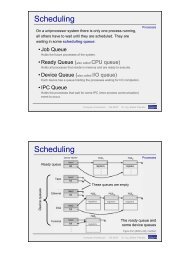
sd Distance Update<br />
loop<br />
ACC CAN Bus Controller<br />
{currentDistance = -1}<br />
alt<br />
ACTIVE_ACC<br />
sendSignal(820,distance)<br />
sendSignal(820,distance)<br />
__ t = t + 25<br />
{currentDistance = currentDistance}<br />
ACTIVE_ACC<br />
sendSignal(820,65535)<br />
__t = t + 101<br />
sendSignal(601, "OFF",0)<br />
DEACTIVE_AC<br />
C<br />
sendSignal(820,distance)<br />
__ t = now<br />
Sensor Multifunctional Display<br />
__ t = now<br />
sendSignal(601, "OFF",0)<br />
Figure 4.1. Sequence Diagram Distance Update<br />
Page 13
Figure 4.2. Sequence Diagram Button Pressed<br />
Page 14
4.2 Sequence Diagram: Increase decrease – CCS (SDID-CCS)<br />
S8: if acc is active and there is an object in front of the car, if the distance is more<br />
than 50 m and the currentspeed is less than desiredspeed then the acc will<br />
increase the current speed, if the current distance is between 45 m and 50 m,<br />
the acc will give command for the acumulator to do nothing, if the current less<br />
then 45 m then the acc will calculate the brake power to brake the car. If the<br />
current distance is 65535 then acc is deactivated.<br />
sd Increase and Decrease<br />
loop<br />
ACC ACC Speed CAN Bus Controller Sensor Actuator Engine ABS Brake Multidisplay<br />
ACTIVE_ACC<br />
ref<br />
alt<br />
Active<br />
distanceUpdate<br />
[ currentDistance > 5000<br />
And currentSpeed < desiredSpeed ]<br />
sendSignal(105,currentSpeed+1)<br />
[ currentDistance < 5000 ]<br />
alt<br />
getCurrentSpeed()<br />
currentSpeed<br />
{current speed = current speed}<br />
[ currentDistance > 4500 ]<br />
[ currentDistance < 4500 ]<br />
calculateBrakePower()<br />
[ currentDistance = 65535 ]<br />
sendSignal(601,"OFF",0)<br />
Deactive<br />
CAN_BUS_CONTROLLED<br />
_BY_ACC<br />
sendSignal(105,currentSpeed-1)<br />
brake(brakePower)<br />
ACTUATOR_CONTR<br />
OLED_BY_ACC<br />
increaseRPM()<br />
noPower()<br />
ACTUATOR_NOT_CON<br />
TROLED_BY_ACC<br />
sendSignal(601,"OFF",0)<br />
ABS_CONTROLLED_<br />
BY_ACC<br />
brake()<br />
ABS_NOT_CONTROL<br />
ED_BY_ACC<br />
Figure 4.3 Sequence Diagram Increase Decrease Speed – Cruise Control<br />
System<br />
4.3 Sequence Diagram: Manual Control and Overridden ACC<br />
Page 15
S9: if accel pedal or brake pedal is pressed and the acc is active then the acc will be<br />
overridden<br />
Figure 4.4 Sequence Diagram Manual Control and Overridden ACC<br />
4.4. Sequence diagrams for Initialization<br />
4.5. Validation<br />
Page 16
• All requirements assigned to the sub problem and also assigned to<br />
corresponding sequence diagram.<br />
• Phenomena of the problem diagram are used in the sequence diagram<br />
• S ∧ A ∧ F R’<br />
• S1 ∧ A2 ∧ F1 ∧ F2 R1<br />
• S2 ∧ A2 ∧ F1 ∧ F2 R2<br />
• S3 ∧ A2 ∧ F1 ∧ F2 R3<br />
• S4 ∧ A2 ∧ F1 ∧ F8 R4<br />
• S5 ∧ A2 ∧ F1 ∧ F9 R5<br />
• S8 ∧ A2 ∧ F1 ∧ F6 R6<br />
• S8 ∧ A2 ∧ F1 ∧ F4 ∧ F12<br />
∧ F13 R7<br />
• All requirements are captured.<br />
• S8 ∧ A3 ∧ F1 ∧ F5 R8<br />
• S8 ∧ A3 ∧ F1 R9<br />
• S8 ∧ A1 ∧ F1 R10<br />
• S6 ∧ A1 ∧ F3 R11<br />
• S7 ∧ A1 ∧ F3 R12<br />
• S9 ∧ A3 ∧ F2 ∧ F3 ∧ F7 <br />
R13<br />
Page 17
Phase 5<br />
5.1 Automatic Cruise Control (ACC) Architecture<br />
5.2 Purpose of each Component:<br />
No Subcomponents needed for this problem.<br />
5.3 Sub Components:<br />
No Subcomponents needed for this problem.<br />
5.4 Automatic Cruise Control System (ACC), Internal Interfaces:<br />
No internal interface.<br />
5.5 Automatic Cruise Control System (ACC), External Interfaces:<br />
Page 18
5.6 Sub problem Relationships:<br />
The sub problem relationship of the component Automatic Cruise control System is<br />
the same as problem diagram relationship in Phase 3.<br />
5.7 Validation:<br />
- All machine interfaces of the problem diagrams are captured.<br />
- The signals in the sequence diagrams are the same as in the external interfaces.<br />
- To each programmable component at least one problem diagram is associated.<br />
- All problem diagrams are associated to the ACC.<br />
- All domains in the problem diagrams being part of the machine are associated to<br />
a component.<br />
- Only one machine domain in the context diagram exists. Its structure is given by<br />
the architecture.<br />
- The purpose of each component is consistent to the associated requirements.<br />
Page 19
Phase 6<br />
6.1 Sequence diagrams for Initialization<br />
6.2 Interface behavior for Control Signal<br />
Page 20
6.3 Interface behavior for Incoming State Signal<br />
6.4 Interface behavior for Distance Signal<br />
Page 21
sd Distance SIgnal<br />
loop<br />
CAN Bus Controller ACC<br />
sendSignal(820,distance)<br />
__ t = now<br />
alt<br />
t = t + 101 __<br />
Active<br />
sendSignal(820,distance)<br />
__ t = t + 25<br />
sendSignal(820,65535)<br />
DEAKTIVE<br />
6.5 Validation<br />
• The sequence diagrams describe as in Phase 4, since all diagrams are reused.<br />
• In interface of Phase 5, all signals are used in at least one sequence<br />
diagram.<br />
• The direction of signal is consistence of Phase 5.<br />
• The signal connect components as connected in the system of Phase 5.<br />
Phase 7<br />
Page 22
7.1 ACC System Architecture<br />
7.1 ACC State Control<br />
7.1.1 ACC State Control Problem Frame<br />
7.1.2 ACC State Control Architecture<br />
7.2 Increase Decrease Control ACC<br />
7.2.1 Increase Decrease Control ACC Problem Frame<br />
Page 23
IncreaseDecrease<br />
Control - ACC<br />
a<br />
b<br />
c<br />
d<br />
Acc<br />
Control<br />
Unit<br />
e<br />
CAN-Bus<br />
ACC Speed<br />
Actuator<br />
ABS<br />
i<br />
j<br />
h<br />
Driver<br />
Multifuntio<br />
f<br />
nal Display<br />
Sensor g<br />
Engine<br />
Brake<br />
7.2.2 Increase Decrease Control ACC Architecture<br />
7.3 Overridden Control ACC<br />
7.3.1 Overridden Control ACC Problem Frame<br />
g<br />
f<br />
n<br />
l<br />
m<br />
o<br />
p<br />
k<br />
R6, R7, R8, R9,R10,<br />
R11, R12<br />
Page 24
7.3.2 Overridden Control Architecture<br />
ACC Machine<br />
7.4 Global Architecture<br />
CAN Bus IAL<br />
driver<br />
CAN Bus<br />
driver<br />
CAN Bus<br />
ACC Application Overridden<br />
MicroController<br />
ACC Speed<br />
Page 25
The components of the global architecture are merged using the following<br />
components of the subproblem architecture.<br />
7.5 Validation<br />
ACC Application<br />
CAN Bus HAL<br />
Actuator HAL<br />
ABS HAL<br />
ACC Application State<br />
ACC Application Increase Decrease<br />
ACC Application Overridden<br />
CAN Bus driver ACC State<br />
CAN Bus driver IncDec<br />
Actuator driver IncDec<br />
ABS driver IncDec<br />
• The subproblem architectures have the same external interfaces as the<br />
problem diagram.<br />
• The phenomena of sequence diagram at the external interfaces are the same<br />
as the signals in the interfaces of the application layer.<br />
• The direction of all signals is consistent to each other and consistence to the<br />
input.<br />
• The architecture has the same external interfaces as the ACC controller<br />
component of the machine architecture developed in phase 5.<br />
The overall architecture contains all components of all subproblem architectures.<br />
Page 26
Phase 8<br />
8.1 ACC Control System Architecture<br />
ACC Machine<br />
Can_Bus_Out Can_Bus_In<br />
Can_Bus_Mic_in<br />
ports_CAN_In<br />
CAN Bus_In_Iff<br />
CAN Bus<br />
IAL<br />
CAN Bus<br />
HAL<br />
CAN Bus<br />
Can_Bus_Mic_Out<br />
ports_CAN_Out<br />
CAN Bus_Out_Iff<br />
ACC Application<br />
Actuator<br />
IAL<br />
Actuator<br />
HAL<br />
MicroController<br />
Actuator<br />
Actuator_ctr<br />
ports_Act<br />
ABS<br />
IAL<br />
ABS<br />
HAL<br />
ABS<br />
Abs_ctr<br />
Actuator_com Abs_com<br />
Actuator_ctr_Iff<br />
8.2 Sequence diagrams for Initialization<br />
port<br />
4<br />
Abs_ctr_Iff<br />
Page 27
8.3 CAN Bus_ACC Control Unit<br />
sd ACC Control Unit<br />
alt<br />
CAN Bus_ACC Control Unit<br />
resumeButtonPushed()<br />
offButtonPushed()<br />
setButtonPushed()<br />
plusButtonPushed()<br />
minusButtonPushed()<br />
8.4 CAN Bus_AccelPedal<br />
Unit = ms<br />
sendSignaltoACC(504)<br />
sendSignaltoACC(505)<br />
sendSignaltoACC(503)<br />
sendSignaltoACC(501)<br />
sendSignaltoACC(502)<br />
Page 28
8.5 CAN Bus_BrakePedal<br />
8.6 CAN Bus_Sensor<br />
sd Sensor<br />
loop<br />
alt<br />
distance(distance)<br />
Distance(65535)<br />
CAN Bus Sensor<br />
t=t+25 -<br />
__t=Now<br />
sendSignal(820,distance)<br />
__t=t+101<br />
sendSignal(820,65535)<br />
Unit = ms<br />
ACC_APLICATION<br />
ACTIVE ACC<br />
DEACTIVE ACC<br />
8.7 ACC Application – SubProblem ACC State<br />
Page 29
sd ACC State Application<br />
alt<br />
ACC Application CAN Bus_ACC Control Unit<br />
ACTIVE ACC<br />
sendSignaltoACC(501)<br />
sendSignal(601,“PLUS“,desiredSpeed)<br />
ACTIVE ACC<br />
ACTIVE ACC<br />
sendSignaltoACC(502)<br />
sendSignal(601,“MINUS“,desiredSpeed)<br />
ACTIVE ACC<br />
ACTIVE ACC<br />
sendSignaltoACC(503)<br />
sendSignal(601,“SET“,desiredSpeed)<br />
ACTIVE ACC<br />
DEACTIVE ACC<br />
sendSignaltoACC(504)<br />
sendSignal(601,“RESUME“,-1)<br />
ACTIVE ACC<br />
ACTIVE ACC<br />
sendSignaltoACC(505)<br />
sendSignal(601,“OFF“,0)<br />
DEACTIVE ACC<br />
sendSignal(601,“PLUS“,desiredSpeed)<br />
sendSignal(601,“MINUS“,desiredSpeed)<br />
sendSignal(601,“SET“,desiredSpeed)<br />
sendSignal(601,“RESUME“,-1)<br />
sendSignal(601,“OFF“,0)<br />
8.8 ACC Application – SubProblem Overriden ACC<br />
Page 30
sd Overriden ACC Application<br />
alt<br />
8.9 Validation<br />
SendSignal(102,power)<br />
SendSignal(101,power)<br />
ACC Application<br />
ACTIVE ACC<br />
OVERRIDEN<br />
sendSignal(102,power)<br />
sendSignal(101,power)<br />
CAN Bus Controlled<br />
All sequence diagrams together describe the same behaviors in Phase 6.<br />
All signals in the interfaces classes of Phase 7 are captured in at least one<br />
sequence diagram.<br />
The direction of the signals are consistent with the required or provided<br />
interfaces of Phase 7.<br />
The signals connect the same components as connected in the software<br />
architecture of Phase 7.<br />
Page 31
Phase 9<br />
9.1 Global Software Architecture<br />
ACC Machine<br />
Can_Bus_Out Can_Bus_In<br />
Can_Bus_Mic_in<br />
ports_CAN_In<br />
CAN Bus_In_Iff<br />
CAN Bus<br />
IAL<br />
CAN Bus<br />
HAL<br />
CAN Bus<br />
Can_Bus_Mic_Out<br />
ports_CAN_Out<br />
CAN Bus_Out_Iff<br />
ACC Application<br />
Actuator<br />
IAL<br />
Actuator<br />
HAL<br />
MicroController<br />
Actuator<br />
ports_Act<br />
9.2 Component ACC Application<br />
s<br />
Actuator_ctr<br />
Actuator_ctr_Iff<br />
9.3 Component ACC_ButtonPress<br />
ABS<br />
IAL<br />
ABS<br />
HAL<br />
ABS<br />
Abs_ctr<br />
Actuator_com Abs_com<br />
port<br />
4<br />
Abs_ctr_Iff<br />
Page 32
ACC_ButtonPress<br />
[desiredSpeed < 120]/<br />
desiredSpeed =<br />
desiredSpeed + 10<br />
sendSignaltoACC(501)/<br />
sendSignal(601,“+“,desiredSpeed)<br />
[else]<br />
sendSignaltoACC(501)<br />
sendSignaltoACC(502)/<br />
sendSignal(601,“-<br />
“,desiredSpeed)<br />
ACTIVE_ACC DEACTIVE_ACC<br />
sendSignaltoACC(505)/<br />
sendSignal(601,“OFF“,0)<br />
sendSignaltoACC(503)/<br />
sendSignal(601,“SET“,desir<br />
edSpeed)<br />
sendSignal(102,power) sendSignal(101,power)<br />
sendSignaltoACC(504)/<br />
activateLastdesiredSpeed()<br />
sendSignal(601,“RESUME“,desi<br />
redSpeed),<br />
OVERRIDEN<br />
9.4 Component Increase Decrease<br />
[desiredSpeed > 40]/<br />
desiredSpeed =<br />
desiredSpeed + 10<br />
[else]<br />
sendSignaltoACC(502)<br />
sendSignaltoACC(504)/<br />
sendSignal(601,“RESUME,-1“)<br />
ACC_ON<br />
Page 33
ACC Increase Decrease<br />
ACTIVE_ACC<br />
[currentDistance4500]/<br />
sendSignal(105,desiredSpeed,N<br />
O_POWER)<br />
Page 34
ABS IAL<br />
ABS_NOT_CONTROLLED_BY_ACC<br />
c<br />
sendSignal(102,power)<br />
ABS__CONTROLLED_BY_ACC<br />
brake(brake)<br />
brake(brake)<br />
9.7 Component ACC IAL Application for CAN Bus<br />
9.8 Component ACC IAL Application for Actuator<br />
sendSignal(102,power)<br />
Page 35
ACTUATOR IAL<br />
ACTUATOR_NOT_CONTROLLED_BY_ACC<br />
c<br />
sendSignal(101,speed)<br />
ACTUATOR_CONTROLLED_BY_ACC<br />
[speedDesiredSpeed]/<br />
noPower()<br />
9.9 Validation<br />
sendSignal(105,speed)<br />
sendSignal(105,speed)<br />
sendSignal(102,brake)<br />
sendSignal(101,speed)<br />
• The state machines behave as described in the sequence diagrams of Step 8.<br />
All states are covered.<br />
• The interface classes are the same as in Phase 7.<br />
• The state machines handle all possible signals in all states.<br />
Page 36
PHASE 10<br />
10.1 Application component<br />
This component implements component<br />
public interface Can_Bus_Out_if {<br />
public void sendSignal(int signal, String value, int desiredSpeed);<br />
}<br />
The implementation of the component is located in<br />
test\acc_g1\Application_test.java<br />
The test cases for the component is located in<br />
test\acc_g1\Component_test.java<br />
The test cases cover the following actions:<br />
• sending the signal from range 100 – 505<br />
• sending the value parameter from range 100 – 505<br />
• check also the state when sending signal 501 - 505<br />
10.2 ACTUATOR IAL<br />
Page 37
This component implements component<br />
public interface Actuator_Ctr_if {<br />
public void sendSignal(int signal, int desiredSpeed);<br />
public void sendSignal(int signal, int desiredSpeed, ActuatorOperation command);<br />
}<br />
The implementation of the component is located in<br />
test\acc_g1\Actuator_IAL_test.java<br />
The test cases for the component is located in<br />
test\acc_g1\Component_test.java<br />
The test cases cover the following actions:<br />
• sending the signal from range -2 until 255<br />
• sending the value to INCREASE and NO_POWER<br />
10.3 ABS IAL<br />
Page 38
This component implements component<br />
public interface Abs_Ctr_if {<br />
public void brake (int brakePower);<br />
}<br />
The implementation of the component is located in<br />
test\acc_g1\ABS_IAL_test.java<br />
The test cases for the component is located in<br />
test\acc_g1\Component_test.java<br />
The test cases cover the following actions:<br />
• sending the brake from range -2 until 255<br />
10.4 CAN BUS IAL<br />
Page 39
This component implements component<br />
public interface Can_Bus_Out_if {<br />
public void sendSignal(int signal, String value, int desiredSpeed);<br />
}<br />
public interface Can_Bus_Mic_Out_if {<br />
public void sendSignaltoACC (int signal, int value);<br />
public void sendSignaltoACC (int signal);<br />
}<br />
The implementation of the component is located in<br />
test\acc_g1\CAN_IAL_test.java<br />
The test cases for the component is located in<br />
test\acc_g1\Component_test.java<br />
The test cases cover the following actions:<br />
• sending the signal from range -2 until 255<br />
• sending value from range -2 until 255<br />
Page 40
• sending value PLUS,MINUS and SET<br />
10.5 Validation<br />
Test cases for Phase-10 are located in<br />
test\acc_g1\ Component_test.java<br />
- In all test cases for 4 software components have been verified<br />
- Test cases cover all components of our application<br />
- No failures were found during the component-testing<br />
Page 41
PHASE 11<br />
11.1 Scenario 1 : press accel to set the speed to 60, then the current distance is 300m then<br />
acc is active and set , then set the desired speed to 120<br />
Test case parameters<br />
Current speed = 60 km/hour<br />
Current Distance = 300 m<br />
ACC : ACTIVE_ACC<br />
Desired Speed = 120 Km/hour<br />
Expected Desired Speed = 120 Km/hour<br />
11.2 Scenario 2 : press accel to set the speed to 60, then the current distance is 300m then<br />
acc is active and set , then set the desired speed to 120 , then the current distance is<br />
changed into 40 m<br />
Test case parameters<br />
Current speed = 60 km/hour<br />
Current Distance = 300 m<br />
ACC : ACTIVE_ACC<br />
Desired Speed = 120 Km/hour<br />
New current Distance = 40m<br />
Expected Brake = 10<br />
11.3 Scenario 3 : press accel to set the speed to 60, then the current distance is 300m then<br />
acc is active and set , then set the desired speed to 120 , then the current distance is<br />
changed into 16 m<br />
Test case parameters<br />
Current speed = 60 km/hour<br />
Page 42
Current Distance = 300 m<br />
ACC : ACTIVE_ACC<br />
Desired Speed = 120 Km/hour<br />
New current Distance = 16m<br />
Expected Brake = 77<br />
11.4 Scenario 4 : press accel to set the speed to 60, then the current distance is 300m then<br />
acc is active and set , then set the desired speed to 120 , then the current distance is<br />
changed into 65535 m<br />
Test case parameters<br />
Current speed = 60 km/hour<br />
Current Distance = 300 m<br />
ACC : ACTIVE_ACC<br />
Desired Speed = 120 Km/hour<br />
New current Distance = 16m<br />
Expected Signal : ( 601 , “OFF”, 0 ) -> signal that show that ACC is deactive<br />
11.5 Validation<br />
Test cases for Phase-11 are located in<br />
test\acc_g1\ Integration_test.java<br />
In all, four integrating test cases have been verified. No failures were found<br />
during the testing.<br />
Page 43