Rexroth IndraMotion MTX - Bosch Rexroth
Rexroth IndraMotion MTX - Bosch Rexroth
Rexroth IndraMotion MTX - Bosch Rexroth

You also want an ePaper? Increase the reach of your titles
YUMPU automatically turns print PDFs into web optimized ePapers that Google loves.
Electric Drives<br />
Linear Motion and<br />
and Controls Hydraulics<br />
Assembly Technologies Pneumatics Service<br />
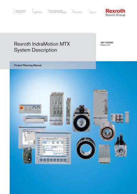
<strong>Rexroth</strong> <strong>IndraMotion</strong> <strong>MTX</strong><br />
System Description<br />
Project Planning Manual<br />
R911322282<br />
Edition 01
<strong>Bosch</strong> <strong>Rexroth</strong> AG | Electric Drives<br />
and Controls<br />
Title<br />
Type of Documentation<br />
Document Typecode<br />
Internal File Reference<br />
Purpose of Documentation<br />
Record of Revision<br />
Copyright<br />
Validity<br />
Published by<br />
Note<br />
<strong>Rexroth</strong> <strong>IndraMotion</strong> <strong>MTX</strong><br />
System Description<br />
Project Planning Manual<br />
DOK-<strong>MTX</strong>***-SYS*DES*V08-PR01-EN-P<br />
RS-45c165917e4818760a6846a00078cc5b-1-en-US-5<br />
This documentation describes the <strong>Rexroth</strong> <strong>IndraMotion</strong> <strong>MTX</strong> system.<br />
Edition Release Date Notes<br />
120-2500-B365-01/EN 11.2007 First edition for 08VRS<br />
© 2007 <strong>Bosch</strong> <strong>Rexroth</strong> AG<br />
Copying this document, giving it to others and the use or communication of the<br />
contents thereof without express authority, are forbidden. Offenders are liable<br />
for the payment of damages. All rights are reserved in the event of the grant of<br />
a patent or the registration of a utility model or design (DIN 34-1).<br />
The specified data is for product description purposes only and may not be<br />
deemed to be guaranteed unless expressly confirmed in the contract. All rights<br />
are reserved with respect to the content of this documentation and the availa‐<br />
bility of the product.<br />
<strong>Bosch</strong> <strong>Rexroth</strong> AG<br />
Bgm.-Dr.-Nebel-Str. 2 ■ 97816 Lohr a. Main, Germany<br />
Phone +49 (0)93 52/ 40-0 ■ Fax +49 (0)93 52/ 40-48 85<br />
http://www.boschrexroth.com/<br />
<strong>Rexroth</strong> <strong>IndraMotion</strong> <strong>MTX</strong> | Project Planning Manual<br />
System Development Machine Tools M. Muthig (SyMu/MePe)<br />
This document has been printed on chlorine-free bleached paper.
Project Planning Manual | <strong>Rexroth</strong> <strong>IndraMotion</strong> <strong>MTX</strong> Electric Drives<br />
and Controls<br />
Table of Contents<br />
| <strong>Bosch</strong> <strong>Rexroth</strong> AG I/VII<br />
Table of Contents<br />
1 System Overview........................................................................................................... 1<br />
1.1 Brief Description..................................................................................................................................... 1<br />
1.1.1 General................................................................................................................................................ 1<br />
1.1.2 Documentation References................................................................................................................. 1<br />
1.2 Overview of Industrial PCs..................................................................................................................... 2<br />
1.3 Characteristics of Standard Industrial PCs............................................................................................. 3<br />
1.4 Characteristics of High-end Industrial PCs............................................................................................. 3<br />
2 Important Instructions on Use........................................................................................ 5<br />
2.1 Intended Use.......................................................................................................................................... 5<br />
2.1.1 Introduction.......................................................................................................................................... 5<br />
2.1.2 Areas of Application and Use.............................................................................................................. 5<br />
2.2 Improper Use.......................................................................................................................................... 5<br />
3 Safety Instructions for Electric Drives and Controls....................................................... 7<br />
3.1 Safety Instructions - General Information............................................................................................... 7<br />
3.1.1 Using the Safety Instructions and Passing them on to Others............................................................ 7<br />
3.1.2 How to Employ the Safety Instructions................................................................................................ 7<br />
3.1.3 Explanation of Warning Symbols and Degrees of Hazard Seriousness.............................................. 8<br />
3.1.4 Hazards by Improper Use.................................................................................................................... 9<br />
3.2 Instructions with Regard to Specific Dangers....................................................................................... 10<br />
3.2.1 Protection Against Contact with Electrical Parts and Housings......................................................... 10<br />
3.2.2 Protection Against Electric Shock by Protective Extra-Low Voltage................................................. 11<br />
3.2.3 Protection Against Dangerous Movements....................................................................................... 11<br />
3.2.4 Protection Against Magnetic and Electromagnetic Fields During Operation and Mounting.............. 14<br />
3.2.5 Protection Against Contact with Hot Parts......................................................................................... 14<br />
3.2.6 Protection During Handling and Mounting......................................................................................... 14<br />
3.2.7 Battery Safety.................................................................................................................................... 15<br />
3.2.8 Protection Against Pressurized Systems........................................................................................... 15<br />
4 CNC Control Modules IndraControl P40 and IndraControl P60................................... 17<br />
4.1 Brief Description................................................................................................................................... 17<br />
4.2 Performance Data................................................................................................................................. 17<br />
4.3 Technical Data...................................................................................................................................... 18<br />
4.4 Battery Buffer Time............................................................................................................................... 18<br />
4.5 Handling................................................................................................................................................ 18<br />
4.5.1 General.............................................................................................................................................. 18<br />
4.5.2 Resistance to Climate........................................................................................................................ 18<br />
Temperature................................................................................................................................... 18<br />
Humidity.......................................................................................................................................... 18<br />
Corrosion / Resistance to Chemicals............................................................................................. 18<br />
4.5.3 Noise Radiation, Immunity (EMC)..................................................................................................... 19<br />
Radio Interference Suppression..................................................................................................... 19<br />
Page
II/VII <strong>Bosch</strong> <strong>Rexroth</strong> AG | Electric Drives<br />
and Controls<br />
Table of Contents<br />
<strong>Rexroth</strong> <strong>IndraMotion</strong> <strong>MTX</strong> | Project Planning Manual<br />
Page<br />
Immunity......................................................................................................................................... 19<br />
4.5.4 Service Concept................................................................................................................................ 19<br />
General........................................................................................................................................... 19<br />
Spare Parts..................................................................................................................................... 19<br />
4.6 Display and Control Components......................................................................................................... 19<br />
4.6.1 LEDs and External Watchdog Reset button...................................................................................... 19<br />
General........................................................................................................................................... 19<br />
Ready Active / Watchdog Error LED.............................................................................................. 20<br />
Power Good / Trigger LED............................................................................................................. 20<br />
OK / Error LED............................................................................................................................... 20<br />
SERCOS LERR LED...................................................................................................................... 20<br />
Watchdog Reset Button.................................................................................................................. 20<br />
4.7 Interfaces.............................................................................................................................................. 21<br />
4.7.1 SERCOS Interface X7S1, X7S2........................................................................................................ 21<br />
4.7.2 PROFIBUS-DP Master Interface X7P............................................................................................... 21<br />
4.7.3 Ethernet Interface X7E...................................................................................................................... 21<br />
4.7.4 Ready Contact................................................................................................................................... 21<br />
4.8 Function Modules................................................................................................................................. 22<br />
4.8.1 General.............................................................................................................................................. 22<br />
4.8.2 High-speed I/O Interface................................................................................................................... 22<br />
General........................................................................................................................................... 22<br />
24 V DC Voltage Connection.......................................................................................................... 22<br />
Digital Outputs................................................................................................................................ 23<br />
Digital Inputs................................................................................................................................... 23<br />
4.8.3 CANopen Double Master................................................................................................................... 25<br />
General........................................................................................................................................... 25<br />
CANopen Interface X7C1, X7C2.................................................................................................... 25<br />
Diagnostics LEDs........................................................................................................................... 26<br />
Power Supply and Voltage Supply................................................................................................. 27<br />
Ambient Conditions........................................................................................................................ 27<br />
4.9 Order Type............................................................................................................................................ 27<br />
4.9.1 General.............................................................................................................................................. 27<br />
4.9.2 Order Codes in Industrial PCs from <strong>Bosch</strong> <strong>Rexroth</strong>.......................................................................... 28<br />
5 CNC Control Module IndraControl L40........................................................................ 29<br />
5.1 Brief Description................................................................................................................................... 29<br />
5.2 Performance Data................................................................................................................................. 29<br />
5.3 Technical Data...................................................................................................................................... 29<br />
5.4 Power Supply........................................................................................................................................ 30<br />
5.5 Ambient Conditions............................................................................................................................... 31<br />
5.6 Display and Control Components......................................................................................................... 32<br />
5.6.1 General.............................................................................................................................................. 32<br />
5.6.2 Display and Control Buttons.............................................................................................................. 32<br />
5.6.3 Reset Button and LED....................................................................................................................... 33<br />
5.7 Interfaces.............................................................................................................................................. 33<br />
5.7.1 SERCOS Interface X7S1, X7S2........................................................................................................ 33
Project Planning Manual | <strong>Rexroth</strong> <strong>IndraMotion</strong> <strong>MTX</strong> Electric Drives<br />
and Controls<br />
| <strong>Bosch</strong> <strong>Rexroth</strong> AG III/VII<br />
Table of Contents<br />
Page<br />
5.7.2 PROFIBUS-DP Master Interface X7P............................................................................................... 33<br />
5.7.3 Ethernet Interface X7E...................................................................................................................... 34<br />
5.7.4 Ready Contact X2R........................................................................................................................... 34<br />
General........................................................................................................................................... 34<br />
X2R Connection Assignment.......................................................................................................... 34<br />
Contact Characteristics.................................................................................................................. 34<br />
Meaning of the LEDs...................................................................................................................... 35<br />
5.7.5 Interface for Compact Flash Card..................................................................................................... 35<br />
5.7.6 Inline Bus........................................................................................................................................... 35<br />
5.7.7 Function Module Pin.......................................................................................................................... 35<br />
5.8 Function Modules................................................................................................................................. 36<br />
5.8.1 SRAM Function Module CFL01.1-Y1................................................................................................ 36<br />
General........................................................................................................................................... 36<br />
Brief Description............................................................................................................................. 36<br />
Technical Data................................................................................................................................ 36<br />
Addressing the Function Module.................................................................................................... 37<br />
5.9 Execution.............................................................................................................................................. 37<br />
5.10 Accessory............................................................................................................................................. 37<br />
5.10.1 SRAM Function Module CFL01.1-Y1................................................................................................ 37<br />
5.10.2 Fan.................................................................................................................................................... 37<br />
5.10.3 Plug Set............................................................................................................................................. 37<br />
5.10.4 Labels................................................................................................................................................ 38<br />
5.10.5 Replacement Battery......................................................................................................................... 38<br />
5.11 Documentation...................................................................................................................................... 38<br />
6 VSP Standard Industrial PC......................................................................................... 39<br />
6.1 Brief Description................................................................................................................................... 39<br />
6.2 Field of Application............................................................................................................................... 39<br />
6.3 Technical Data...................................................................................................................................... 40<br />
6.4 Wear Parts............................................................................................................................................ 40<br />
6.5 Types.................................................................................................................................................... 40<br />
6.6 Control Configuration............................................................................................................................ 40<br />
6.7 Accessory............................................................................................................................................. 41<br />
6.7.1 Connectors and Cable Assemblies................................................................................................... 41<br />
6.8 Documentation...................................................................................................................................... 41<br />
7 VSB Standard Industrial PC with VDP Operator Panel............................................... 43<br />
7.1 Brief Description................................................................................................................................... 43<br />
7.2 Field of Application............................................................................................................................... 43<br />
7.3 Technical Data...................................................................................................................................... 44<br />
7.3.1 VSB 40.1........................................................................................................................................... 44<br />
7.3.2 VDP 16/40......................................................................................................................................... 44<br />
7.4 Wear Parts............................................................................................................................................ 44<br />
7.5 Types.................................................................................................................................................... 44<br />
7.6 Control Configuration............................................................................................................................ 45
IV/VII <strong>Bosch</strong> <strong>Rexroth</strong> AG | Electric Drives<br />
and Controls<br />
Table of Contents<br />
<strong>Rexroth</strong> <strong>IndraMotion</strong> <strong>MTX</strong> | Project Planning Manual<br />
Page<br />
7.7 Accessory............................................................................................................................................. 45<br />
7.7.1 Connection Cables (GIGASTAR interface)....................................................................................... 45<br />
7.7.2 Fastening Bracket.............................................................................................................................. 45<br />
7.8 Documentation...................................................................................................................................... 46<br />
8 VPP High-End Industrial PC........................................................................................ 47<br />
8.1 Brief Description................................................................................................................................... 47<br />
8.2 Field of Application............................................................................................................................... 47<br />
8.3 Technical Data...................................................................................................................................... 48<br />
8.4 Wear parts............................................................................................................................................ 48<br />
8.5 Types.................................................................................................................................................... 48<br />
8.6 Control Configuration............................................................................................................................ 48<br />
8.7 Accessory............................................................................................................................................. 49<br />
8.7.1 Connectors and Cable Assemblies................................................................................................... 49<br />
8.8 Documentation...................................................................................................................................... 49<br />
9 VPB 40 High-End Industrial PC with VDP Operator Panel.......................................... 51<br />
9.1 General................................................................................................................................................. 51<br />
9.2 Types.................................................................................................................................................... 51<br />
9.3 Field of Application............................................................................................................................... 51<br />
9.4 Technical Data...................................................................................................................................... 52<br />
9.4.1 VPB 40.............................................................................................................................................. 52<br />
9.4.2 VDP 16/40......................................................................................................................................... 52<br />
9.5 Wear parts............................................................................................................................................ 52<br />
9.6 Types.................................................................................................................................................... 52<br />
9.7 Control Configurations.......................................................................................................................... 53<br />
9.8 Accessory............................................................................................................................................. 53<br />
9.8.1 Connection Cables (GIGASTAR interface)....................................................................................... 53<br />
9.8.2 Fastening Bracket.............................................................................................................................. 53<br />
9.9 Documentation...................................................................................................................................... 53<br />
10 External Battery Pack.................................................................................................. 55<br />
10.1 Brief Description................................................................................................................................... 55<br />
10.2 Technical Data...................................................................................................................................... 55<br />
10.3 Ambient Conditions............................................................................................................................... 56<br />
10.4 Execution.............................................................................................................................................. 57<br />
10.5 Accessory............................................................................................................................................. 57<br />
10.5.1 Connection Cable.............................................................................................................................. 57<br />
10.6 Documentation...................................................................................................................................... 57<br />
11 UPS Uninterrupted Power Supply................................................................................ 59<br />
11.1 Brief Description................................................................................................................................... 59<br />
11.2 Execution.............................................................................................................................................. 59<br />
11.3 Accessory............................................................................................................................................. 59<br />
11.3.1 Holder................................................................................................................................................ 59
Project Planning Manual | <strong>Rexroth</strong> <strong>IndraMotion</strong> <strong>MTX</strong> Electric Drives<br />
and Controls<br />
| <strong>Bosch</strong> <strong>Rexroth</strong> AG V/VII<br />
Table of Contents<br />
Page<br />
11.4 Settings Operating System................................................................................................................... 59<br />
11.4.1 General.............................................................................................................................................. 59<br />
11.4.2 Setting "Idle State"............................................................................................................................. 59<br />
11.4.3 Setting "APM".................................................................................................................................... 60<br />
11.5 Documentation...................................................................................................................................... 61<br />
12 VAM Machine Control Panel........................................................................................ 63<br />
12.1 Brief Description................................................................................................................................... 63<br />
12.2 Types.................................................................................................................................................... 64<br />
12.3 Accessory............................................................................................................................................. 64<br />
12.3.1 Connection Cables (PROFIBUS Interface)....................................................................................... 64<br />
12.4 Documentation...................................................................................................................................... 64<br />
13 VAK PC Keyboards...................................................................................................... 65<br />
13.1 General................................................................................................................................................. 65<br />
13.2 Slide-out Keyboards............................................................................................................................. 65<br />
13.3 Built-in Keyboards................................................................................................................................. 65<br />
13.4 Types.................................................................................................................................................... 66<br />
13.5 Documentation...................................................................................................................................... 66<br />
14 RECO Inline Modules.................................................................................................. 67<br />
14.1 Brief Description................................................................................................................................... 67<br />
14.2 Components......................................................................................................................................... 67<br />
14.3 Documentation...................................................................................................................................... 67<br />
15 VCP Mini Control Panel............................................................................................... 69<br />
15.1 Brief Description................................................................................................................................... 69<br />
15.2 Technical Data...................................................................................................................................... 70<br />
15.3 Types.................................................................................................................................................... 70<br />
15.4 Accessory............................................................................................................................................. 70<br />
15.4.1 Connection Cables (PROFIBUS Interface)....................................................................................... 70<br />
15.5 Documentation...................................................................................................................................... 71<br />
16 RECO Fieldline Modules.............................................................................................. 73<br />
16.1 Brief Description................................................................................................................................... 73<br />
16.2 Components......................................................................................................................................... 73<br />
16.3 Documentation...................................................................................................................................... 73<br />
17 Firmware and Software for the <strong>IndraMotion</strong> <strong>MTX</strong>........................................................ 75<br />
17.1 General................................................................................................................................................. 75<br />
17.2 Operating System for PC-based Controls............................................................................................ 75<br />
17.3 Basis Software for the <strong>IndraMotion</strong> <strong>MTX</strong>.............................................................................................. 75<br />
17.3.1 System-comprehensive Basis Software............................................................................................ 75<br />
17.3.2 <strong>IndraMotion</strong> <strong>MTX</strong> - Operation and Engineering................................................................................. 75
VI/VII <strong>Bosch</strong> <strong>Rexroth</strong> AG | Electric Drives<br />
and Controls<br />
Table of Contents<br />
<strong>Rexroth</strong> <strong>IndraMotion</strong> <strong>MTX</strong> | Project Planning Manual<br />
Page<br />
17.3.3 <strong>IndraMotion</strong> <strong>MTX</strong> - Operation............................................................................................................ 76<br />
17.3.4 <strong>IndraMotion</strong> <strong>MTX</strong> - Kommunikation................................................................................................... 76<br />
17.3.5 <strong>IndraMotion</strong> <strong>MTX</strong> - Simulator............................................................................................................. 76<br />
17.4 Basis Firmware for the <strong>IndraMotion</strong> <strong>MTX</strong>............................................................................................. 77<br />
17.4.1 Firmware for the <strong>MTX</strong> Standard........................................................................................................ 77<br />
17.4.2 Firmware for the <strong>MTX</strong> Performance.................................................................................................. 77<br />
17.4.3 Firmware for the <strong>MTX</strong> Compact........................................................................................................ 77<br />
17.5 Software and Firmware Options........................................................................................................... 78<br />
17.5.1 <strong>IndraMotion</strong> <strong>MTX</strong> SWW Firmware..................................................................................................... 78<br />
17.5.2 8 Servo Axes - 2 Channels................................................................................................................ 78<br />
17.5.3 Technology Package Turning – Level 1............................................................................................ 78<br />
17.5.4 Technology Package "Shop Floor Programming Turning"................................................................ 79<br />
17.5.5 Machining Center Level 1.................................................................................................................. 79<br />
17.5.6 Machining Center Level 2.................................................................................................................. 79<br />
17.5.7 Technology Package "Shop Floor Programming Milling".................................................................. 80<br />
17.5.8 Technology Package Producing Gears / Electronic Gears............................................................... 80<br />
17.5.9 IndraWorks View3D........................................................................................................................... 80<br />
17.5.10 IndraWorks I-Remote........................................................................................................................ 81<br />
18 Applications.................................................................................................................. 83<br />
18.1 VSP 16 Standard Industrial PC............................................................................................................ 83<br />
18.2 VSP 40 Standard Industrial PC............................................................................................................ 84<br />
18.3 VSB 40 Standard Industrial PC with VDP 16 Operator Panel.............................................................. 85<br />
18.4 VSB 40 Standard Industrial PC with VDP 40 Operator Panel.............................................................. 86<br />
18.5 VPP 16 High-end Industrial PC............................................................................................................ 87<br />
18.6 VPP 40 High-end Industrial PC............................................................................................................ 88<br />
18.7 VPB 40 High-end Industrial PC with VDP 16 Operator Panel.............................................................. 89<br />
18.8 VPB 40 High-end Industrial PC with VDP 40 Operator Panel.............................................................. 90<br />
18.9 <strong>MTX</strong> Compact with CML40.2................................................................................................................ 91<br />
19 Data Backup................................................................................................................ 93<br />
19.1 Introduction........................................................................................................................................... 93<br />
19.1.1 Overview............................................................................................................................................ 93<br />
19.1.2 Why Back Up Data?.......................................................................................................................... 93<br />
19.1.3 Definition of Hardware and Software Requirements......................................................................... 93<br />
19.2 Introduction to the System.................................................................................................................... 93<br />
19.2.1 General.............................................................................................................................................. 93<br />
19.2.2 Acronis True Image........................................................................................................................... 94<br />
19.2.3 Archive Files...................................................................................................................................... 94<br />
19.2.4 Incremental Backup........................................................................................................................... 95<br />
19.3 Acronis Secure Zone and Startup Recovery Manager......................................................................... 95<br />
19.3.1 General.............................................................................................................................................. 95<br />
19.3.2 Creating the Acronis Secure Zone.................................................................................................... 96<br />
19.3.3 Resizing the Acronis Secure Zone.................................................................................................... 96<br />
19.3.4 Reactivating Acronis Startup Recovery Manager.............................................................................. 97
Project Planning Manual | <strong>Rexroth</strong> <strong>IndraMotion</strong> <strong>MTX</strong> Electric Drives<br />
and Controls<br />
| <strong>Bosch</strong> <strong>Rexroth</strong> AG VII/VII<br />
Table of Contents<br />
Page<br />
19.4 Creating Image Archives...................................................................................................................... 97<br />
19.5 Checking Image Archives..................................................................................................................... 98<br />
19.6 Updating and Extending Image Archives.............................................................................................. 99<br />
19.7 Restoring Image Archives..................................................................................................................... 99<br />
19.8 Searching Image Archives.................................................................................................................. 102<br />
19.8.1 General............................................................................................................................................ 102<br />
19.8.2 Connecting an Image Archive as a Drive........................................................................................ 102<br />
19.8.3 Cancelling the Drive Connection..................................................................................................... 102<br />
19.9 Creating Bootable Rescue Media....................................................................................................... 102<br />
19.10 Network Support................................................................................................................................. 103<br />
19.10.1 Windows Software........................................................................................................................... 103<br />
19.10.2 Bootable Rescue Media or Recovery Manager............................................................................... 103<br />
19.11 Scheduling a Task.............................................................................................................................. 104<br />
20 Service and Support.................................................................................................. 105<br />
20.1 Helpdesk............................................................................................................................................. 105<br />
20.2 Service Hotline.................................................................................................................................... 105<br />
20.3 Internet................................................................................................................................................ 105<br />
20.4 Helpful Information.............................................................................................................................. 105<br />
Index.......................................................................................................................... 107
<strong>Bosch</strong> <strong>Rexroth</strong> AG | Electric Drives<br />
and Controls<br />
<strong>Rexroth</strong> <strong>IndraMotion</strong> <strong>MTX</strong> | Project Planning Manual
Project Planning Manual | <strong>Rexroth</strong> <strong>IndraMotion</strong> <strong>MTX</strong> Electric Drives<br />
and Controls<br />
1 System Overview<br />
1.1 Brief Description<br />
1.1.1 General<br />
1.1.2 Documentation References<br />
| <strong>Bosch</strong> <strong>Rexroth</strong> AG 1/107<br />
System Overview<br />
The <strong>IndraMotion</strong> <strong>MTX</strong> is a customized configurable CNC control system that<br />
can be used with both single machines and complex high-throughput systems<br />
for automatic production. With its uniform hardware and software, the Indra‐<br />
Motion <strong>MTX</strong> can be individually scaled in terms of performance and functions.<br />
Presently, 3 system variants are available:<br />
● <strong>IndraMotion</strong> <strong>MTX</strong> compact, based on the IndraControl L40 control module<br />
● <strong>IndraMotion</strong> <strong>MTX</strong> standard, based on the IndraControl P40 control module<br />
● <strong>IndraMotion</strong> <strong>MTX</strong> performance, based on the IndraControl P60 control<br />
module<br />
All the control modules provide both CNC and PLC functions. The highest con‐<br />
figuration provides CNC performance allowing activation of up to 64 axes in 12<br />
independent CNC processing channels. The standard equipment of the control<br />
modules includes interfaces allowing the activation of I/Os via PROFIBUS-<br />
DP, of intelligent drives via the SERCOS interface and of peripheral assemblies<br />
via Ethernet. A high-speed interface permits the module to be supplemented<br />
by additional field buses (DeviceNet, CANOpen) or interfaces.<br />
The IndraControl L40 control module in terminal format has been designed on<br />
a switch cabinet for top hat rail assembly. Control modules IndraControl P40<br />
and IndraControl P60 are designed as PCI slot modules and are inserted into<br />
a free slot of an industrial PC.<br />
<strong>Bosch</strong> <strong>Rexroth</strong> provides industrial PCs with various designs and screen sizes;<br />
these can be used with control modules IndraControl P40 and IndraControl<br />
P60. In their design and construction, the control panels of the industrial PCs<br />
have been adapted to further components (machine control panels and PC<br />
keyboards) so that they present an optimum solution for controlling, operating<br />
and visualizing a machine tool.<br />
Inline modules to be installed in switch cabinets and Fieldline modules for in‐<br />
stallation in the vicinity of a machine provide scalable I/O systems with PRO‐<br />
FIBUS-DP and DeviceNet.<br />
Accessories also include cable assemblies allowing the <strong>IndraMotion</strong> <strong>MTX</strong> con‐<br />
trol system to be wired in no time.<br />
Documentation Type Material number<br />
<strong>Rexroth</strong> IndraControl VSP 16.1/40.1 DOK-SUPPL*-VSP*16/40**-PRxx-EN-P R911308263<br />
<strong>Rexroth</strong> IndraControl VDP 16.2/40.2 DOK-SUPPL*-VDP*XX.2***-PRxx-EN-P R911313007<br />
<strong>Rexroth</strong> IndraControl VPP 16.1/40.1/60.1 DOK-SUPPL*-VPP*XX.1***-PRxx-EN-P R911311819<br />
<strong>Rexroth</strong> IndraControl VCP 02 DOK-SUPPL*-VCP02******-PRxx-EN-P R911299727<br />
<strong>Rexroth</strong> IndraControl VCP 05 DOK-SUPPL*-VCP05******-PRxx-EN-P R911299725<br />
<strong>Rexroth</strong> IndraControl VCP 08 DOK-SUPPL*-VCP08******-PRxx-EN-P R911299723<br />
<strong>Rexroth</strong> IndraControl VCP 20 DOK-SUPPL*-VCP20******-PRxx-EN-P R911299721<br />
<strong>Rexroth</strong> IndraControl VCP 25 DOK-SUPPL*-VCP25******-PRxx-EN-P R911299719<br />
<strong>Rexroth</strong> IndraControl L40 DOK-CONTRL-IC*L40*****-PRxx-EN-P R911308428
2/107 <strong>Bosch</strong> <strong>Rexroth</strong> AG | Electric Drives<br />
and Controls<br />
System Overview<br />
Documentation Type Material number<br />
<strong>Rexroth</strong> VSB 40.1 DOK-SUPPL*-VSB*40.1***-PRxx-EN-P R911310078<br />
<strong>Rexroth</strong> VPB 40.1 DOK-SUPPL*-VPB*40.1***-PRxx-EN-P R911312596<br />
<strong>Rexroth</strong> VAM 11.1/41.1 DOK-SUPPL*-VAM*11/41**-PRxx-EN-P R911308617<br />
<strong>Rexroth</strong> VAM 10.1/40.1 DOK-SUPPL*-VAM*10/40**-PRxx-EN-P R911306780<br />
<strong>Rexroth</strong> VAK 10.1/40.1 DOK-SUPPL*-VAK*40.1***-PRxx-EN-P R911311649<br />
<strong>Rexroth</strong> VAK 11/41 DOK-SUPPL*-VAK*11/41**-PRxx-EN-P R911310335<br />
<strong>Rexroth</strong> RECO Inline, PROFIBUS-DP DOK-CONTRL-R-IL*PBSSYS-AWxx-EN-P R911289596<br />
<strong>Rexroth</strong> RECO Inline, PROFIBUS-DP Terminal and<br />
Module Power Supply<br />
<strong>Rexroth</strong> RECO Inline, Digital Input/Output Termi‐<br />
nals<br />
DOK-CONTRL-R-IL*PB*-BK-FKxx-EN-P R911289586<br />
DOK-CONTRL-R-IL*DIO***-FKxx-EN-P R911289588<br />
<strong>Rexroth</strong> Fieldline, PROFIBUS Devices DOK-CONTRL-RF-FLS-PB**-PRxx-EN-P R911298517<br />
Fig.1-1: Documentation references<br />
1.2 Overview of Industrial PCs<br />
Fig.1-2: Overview of Industrial PCs<br />
<strong>Rexroth</strong> <strong>IndraMotion</strong> <strong>MTX</strong> | Project Planning Manual
Project Planning Manual | <strong>Rexroth</strong> <strong>IndraMotion</strong> <strong>MTX</strong> Electric Drives<br />
and Controls<br />
1.3 Characteristics of Standard Industrial PCs<br />
● Normal capability for industrial environments (vibration during operation:<br />
0.25 g; shock load: 5 g)<br />
● Standard investment reliability (high component innovation rate)<br />
● Latest PC technology (current processors, motherboards, etc.; available<br />
with compatible functions for at least 2 years)<br />
1.4 Characteristics of High-end Industrial PCs<br />
| <strong>Bosch</strong> <strong>Rexroth</strong> AG 3/107<br />
● High capability for industrial environments (vibration: 1 g; shock load: 15<br />
g)<br />
● High investment reliability (high component continuity rate)<br />
System Overview<br />
● Long-term availability of components (long-term availability of processors,<br />
motherboards, etc.; available with compatible software and functionality<br />
for at least 5 years)
<strong>Bosch</strong> <strong>Rexroth</strong> AG | Electric Drives<br />
and Controls<br />
<strong>Rexroth</strong> <strong>IndraMotion</strong> <strong>MTX</strong> | Project Planning Manual
Project Planning Manual | <strong>Rexroth</strong> <strong>IndraMotion</strong> <strong>MTX</strong> Electric Drives<br />
and Controls<br />
2 Important Instructions on Use<br />
2.1 Intended Use<br />
2.1.1 Introduction<br />
2.1.2 Areas of Application and Use<br />
2.2 Improper Use<br />
<strong>Bosch</strong> <strong>Rexroth</strong> products are developed and manufactured according to the<br />
state of the art. Before delivery, they are checked for operational safety.<br />
The products may only be used in the proper manner. If they are not used as<br />
intended, situations may arise which result in damage to personnel or material.<br />
<strong>Bosch</strong> <strong>Rexroth</strong>, as the manufacturer of the products, will not as‐<br />
sume any warranty, liability or payment of damages in case of<br />
damage resulting from improper use of the products. If he fails to<br />
use the products as intended, the user will be solely responsible for<br />
any resulting risks.<br />
Before using <strong>Bosch</strong> <strong>Rexroth</strong> products, the following prerequisites must be ful‐<br />
filled to ensure that they are used as intended:<br />
● Everyone who in any way deals with one of our products must read and<br />
understand the corresponding notes regarding safety and proper use.<br />
● If the products are hardware, they must be kept in their original state, i.e.<br />
no constructional modifications may be made. Software products may not<br />
be decompiled; their source codes may not be modified.<br />
● Damaged or improperly working products must not be installed or put into<br />
operation.<br />
● It must be ensured that the products are installed according to the regu‐<br />
lations mentioned in the documentation.<br />
For the areas of use and application of each component , also see the associ‐<br />
ated documents (see chapter 1.1.2 "Documentation References" on page 1).<br />
Using the devices outside of the above-referenced areas of application or under<br />
operating conditions other than described in the document and the technical<br />
data specified is defined as "improper use".<br />
The device may not be used if<br />
| <strong>Bosch</strong> <strong>Rexroth</strong> AG 5/107<br />
Important Instructions on Use<br />
● it is exposed to operating conditions which do not correspond to the speci‐<br />
fied ambient conditions. For example, they must not be operated under<br />
water, under extreme temperature fluctuations, or in extreme maximum<br />
temperatures.<br />
● Furthermore, the devices must not be used in any applications not ex‐<br />
pressly approved by <strong>Bosch</strong> <strong>Rexroth</strong>. In this connection, observance of the<br />
statements in the General Safety Notes is imperative!
<strong>Bosch</strong> <strong>Rexroth</strong> AG | Electric Drives<br />
and Controls<br />
<strong>Rexroth</strong> <strong>IndraMotion</strong> <strong>MTX</strong> | Project Planning Manual
Project Planning Manual | <strong>Rexroth</strong> <strong>IndraMotion</strong> <strong>MTX</strong> Electric Drives<br />
and Controls<br />
3 Safety Instructions for Electric Drives and Controls<br />
3.1 Safety Instructions - General Information<br />
3.1.1 Using the Safety Instructions and Passing them on to Others<br />
WARNING<br />
Do not attempt to install or commission this device without first reading all doc‐<br />
umentation provided with the product. Read and understand these safety<br />
instructions and all user documentation prior to working with the device. If you<br />
do not have the user documentation for the device, contact your responsible<br />
<strong>Bosch</strong> <strong>Rexroth</strong> sales representative. Ask for these documents to be sent im‐<br />
mediately to the person or persons responsible for the safe operation of the<br />
device.<br />
If the device is resold, rented and/or passed on to others in any other form,<br />
these safety instructions must be delivered with the device in the official lan‐<br />
guage of the user's country.<br />
Improper use of these devices, failure to follow the safety instructions in<br />
this document or tampering with the product, including disabling of safe‐<br />
ty devices, may result in material damage, bodily harm, electric shock<br />
or even death!<br />
Observe the safety instructions!<br />
3.1.2 How to Employ the Safety Instructions<br />
| <strong>Bosch</strong> <strong>Rexroth</strong> AG 7/107<br />
Safety Instructions for Electric Drives and Controls<br />
Read these instructions before initial commissioning of the equipment in order<br />
to eliminate the risk of bodily harm and/or material damage. Follow these safety<br />
instructions at all times.<br />
● <strong>Bosch</strong> <strong>Rexroth</strong> AG is not liable for damages resulting from failure to ob‐<br />
serve the warnings provided in this documentation.<br />
● Read the operating, maintenance and safety instructions in your language<br />
before commissioning the machine. If you find that you cannot completely<br />
understand the documentation for your product, please ask your supplier<br />
to clarify.<br />
● Proper and correct transport, storage, assembly and installation, as well<br />
as care in operation and maintenance, are prerequisites for optimal and<br />
safe operation of this device.<br />
● Only assign trained and qualified persons to work with electrical installa‐<br />
tions:<br />
– Only persons who are trained and qualified for the use and operation<br />
of the device may work on this device or within its proximity. The<br />
persons are qualified if they have sufficient knowledge of the assem‐<br />
bly, installation and operation of the product, as well as an under‐<br />
standing of all warnings and precautionary measures noted in these<br />
instructions.<br />
– Furthermore, they must be trained, instructed and qualified to switch<br />
electrical circuits and devices on and off in accordance with technical<br />
safety regulations, to ground them and to mark them according to the<br />
requirements of safe work practices. They must have adequate safe‐<br />
ty equipment and be trained in first aid.<br />
● Only use spare parts and accessories approved by the manufacturer.
8/107 <strong>Bosch</strong> <strong>Rexroth</strong> AG | Electric Drives<br />
and Controls<br />
Safety Instructions for Electric Drives and Controls<br />
● Follow all safety regulations and requirements for the specific application<br />
as practiced in the country of use.<br />
● The devices have been designed for installation in industrial machinery.<br />
● The ambient conditions given in the product documentation must be ob‐<br />
served.<br />
● Only use safety-relevant applications that are clearly and explicitly ap‐<br />
proved in the Project Planning Manual. If this is not the case, they are<br />
excluded. Safety-relevant are all such applications which can cause dan‐<br />
ger to persons and material damage.<br />
● The information given in the documentation of the product with regard to<br />
the use of the delivered components contains only examples of applica‐<br />
tions and suggestions.<br />
The machine and installation manufacturer must<br />
– make sure that the delivered components are suited for his individual<br />
application and check the information given in this documentation<br />
with regard to the use of the components,<br />
– make sure that his application complies with the applicable safety<br />
regulations and standards and carry out the required measures,<br />
modifications and complements.<br />
● Commissioning of the delivered components is only permitted once it is<br />
sure that the machine or installation in which they are installed complies<br />
with the national regulations, safety specifications and standards of the<br />
application.<br />
● Operation is only permitted if the national EMC regulations for the appli‐<br />
cation are met.<br />
● The instructions for installation in accordance with EMC requirements can<br />
be found in the section on EMC in the respective documentation (Project<br />
Planning Manuals of components and system).<br />
The machine or installation manufacturer is responsible for compliance<br />
with the limiting values as prescribed in the national regulations.<br />
● Technical data, connection and installation conditions are specified in the<br />
product documentation and must be followed at all times.<br />
National regulations which the user must take into account<br />
● European countries: according to European EN standards<br />
● United States of America (USA):<br />
– National Electrical Code (NEC)<br />
– National Electrical Manufacturers Association (NEMA), as well as<br />
local engineering regulations<br />
– regulations of the National Fire Protection Association (NFPA)<br />
● Canada: Canadian Standards Association (CSA)<br />
● Other countries:<br />
<strong>Rexroth</strong> <strong>IndraMotion</strong> <strong>MTX</strong> | Project Planning Manual<br />
– International Organization for Standardization (ISO)<br />
– International Electrotechnical Commission (IEC)<br />
3.1.3 Explanation of Warning Symbols and Degrees of Hazard Seriousness<br />
The safety instructions describe the following degrees of hazard seriousness.<br />
The degree of hazard seriousness informs about the consequences resulting<br />
from non-compliance with the safety instructions:
Project Planning Manual | <strong>Rexroth</strong> <strong>IndraMotion</strong> <strong>MTX</strong> Electric Drives<br />
and Controls<br />
3.1.4 Hazards by Improper Use<br />
DANGER<br />
DANGER<br />
WARNING<br />
WARNING<br />
CAUTION<br />
CAUTION<br />
Warning symbol Signal word<br />
Danger<br />
Warning<br />
Caution<br />
Fig.3-1: Hazard classification (according to ANSI Z 535)<br />
Degree of hazard serious‐<br />
ness acc. to ANSI Z<br />
535.4-2002<br />
Death or severe bodily harm<br />
will occur.<br />
Death or severe bodily harm<br />
may occur.<br />
Minor or moderate bodily<br />
harm or material damage<br />
may occur.<br />
High electric voltage and high working current! Risk of death or severe<br />
bodily injury by electric shock!<br />
Observe the safety instructions!<br />
Dangerous movements! Danger to life, severe bodily harm or material<br />
damage by unintentional motor movements!<br />
Observe the safety instructions!<br />
High electric voltage because of incorrect connection! Risk of death or<br />
bodily injury by electric shock!<br />
Observe the safety instructions!<br />
Health hazard for persons with heart pacemakers, metal implants and<br />
hearing aids in proximity to electrical equipment!<br />
Observe the safety instructions!<br />
Hot surfaces on device housing! Danger of injury! Danger of burns!<br />
Observe the safety instructions!<br />
Risk of injury by improper handling! Risk of bodily injury by bruising,<br />
shearing, cutting, hitting or improper handling of pressurized lines!<br />
Observe the safety instructions!<br />
| <strong>Bosch</strong> <strong>Rexroth</strong> AG 9/107<br />
Safety Instructions for Electric Drives and Controls
10/107 <strong>Bosch</strong> <strong>Rexroth</strong> AG | Electric Drives<br />
and Controls<br />
Safety Instructions for Electric Drives and Controls<br />
CAUTION<br />
Risk of injury by improper handling of batteries!<br />
Observe the safety instructions!<br />
3.2 Instructions with Regard to Specific Dangers<br />
3.2.1 Protection Against Contact with Electrical Parts and Housings<br />
DANGER<br />
<strong>Rexroth</strong> <strong>IndraMotion</strong> <strong>MTX</strong> | Project Planning Manual<br />
This section concerns devices and drive components with voltages<br />
of more than 50 Volt.<br />
Contact with parts conducting voltages above 50 Volts can cause personal<br />
danger and electric shock. When operating electrical equipment, it is unavoid‐<br />
able that some parts of the devices conduct dangerous voltage.<br />
High electrical voltage! Danger to life, electric shock and severe bodily<br />
injury!<br />
● Only those trained and qualified to work with or on electrical equipment<br />
are permitted to operate, maintain and repair this equipment.<br />
● Follow general construction and safety regulations when working on pow‐<br />
er installations.<br />
● Before switching on the device, the equipment grounding conductor must<br />
have been non-detachably connected to all electrical equipment in ac‐<br />
cordance with the connection diagram.<br />
● Do not operate electrical equipment at any time, even for brief measure‐<br />
ments or tests, if the equipment grounding conductor is not permanently<br />
connected to the mounting points of the components provided for this<br />
purpose.<br />
● Before working with electrical parts with voltage potentials higher than<br />
50 V, the device must be disconnected from the mains voltage or power<br />
supply unit. Provide a safeguard to prevent reconnection.<br />
● With electrical drive and filter components, observe the following:<br />
Wait 30 minutes after switching off power to allow capacitors to discharge<br />
before beginning to work. Measure the electric voltage on the capacitors<br />
before beginning to work to make sure that the equipment is safe to touch.<br />
● Never touch the electrical connection points of a component while power<br />
is turned on. Do not remove or plug in connectors when the component<br />
has been powered.<br />
● Install the covers and guards provided with the equipment properly before<br />
switching the device on. Before switching the equipment on, cover and<br />
safeguard live parts safely to prevent contact with those parts.<br />
● A residual-current-operated circuit-breaker or r.c.d. cannot be used for<br />
electric drives! Indirect contact must be prevented by other means, for<br />
example, by an overcurrent protective device according to the relevant<br />
standards.<br />
● Secure built-in devices from direct touching of electrical parts by providing<br />
an external housing, for example a control cabinet.
Project Planning Manual | <strong>Rexroth</strong> <strong>IndraMotion</strong> <strong>MTX</strong> Electric Drives<br />
and Controls<br />
DANGER<br />
For electrical drive and filter components with voltages of more than<br />
50 volts, observe the following additional safety instructions.<br />
High housing voltage and high leakage current! Risk of death or bodily<br />
injury by electric shock!<br />
● Before switching on, the housings of all electrical equipment and motors<br />
must be connected or grounded with the equipment grounding conductor<br />
to the grounding points. This is also applicable before short tests.<br />
● The equipment grounding conductor of the electrical equipment and the<br />
devices must be non-detachably and permanently connected to the power<br />
supply unit at all times. The leakage current is greater than 3.5 mA.<br />
● Over the total length, use copper wire of a cross section of a minimum of<br />
10 mm 2 for this equipment grounding connection!<br />
● Before commissioning, also in trial runs, always attach the equipment<br />
grounding conductor or connect to the ground wire. Otherwise, high vol‐<br />
tages may occur at the housing causing electric shock.<br />
3.2.2 Protection Against Electric Shock by Protective Extra-Low Voltage<br />
WARNING<br />
Protective extra-low voltage is used to allow connecting devices with basic in‐<br />
sulation to extra-low voltage circuits.<br />
All connections and terminals with voltages between 5 and 50 volts at <strong>Rexroth</strong><br />
products are PELV systems. 1) It is therefore allowed to connect devices<br />
equipped with basic insulation (such as programming devices, PCs, notebooks,<br />
display units) to these connections and terminals.<br />
High electric voltage by incorrect connection! Risk of death or bodily<br />
injury by electric shock!<br />
If extra-low voltage circuits of devices containing voltages and circuits of more<br />
than 50 volts (e.g. the mains connection) are connected to <strong>Rexroth</strong> products,<br />
the connected extra-low voltage circuits must comply with the requirements for<br />
PELV. 2)<br />
3.2.3 Protection Against Dangerous Movements<br />
Dangerous movements can be caused by faulty control of connected motors.<br />
Some common examples are:<br />
● improper or wrong wiring of cable connections<br />
● incorrect operation of the equipment components<br />
● wrong input of parameters before operation<br />
● malfunction of sensors, encoders and monitoring devices<br />
● defective components<br />
● software or firmware errors<br />
Dangerous movements can occur immediately after equipment is switched on<br />
or even after an unspecified time of trouble-free operation.<br />
1) "Protective Extra-Low Voltage"<br />
2) "Protective Extra-Low Voltage"<br />
| <strong>Bosch</strong> <strong>Rexroth</strong> AG 11/107<br />
Safety Instructions for Electric Drives and Controls
12/107 <strong>Bosch</strong> <strong>Rexroth</strong> AG | Electric Drives<br />
and Controls<br />
Safety Instructions for Electric Drives and Controls<br />
<strong>Rexroth</strong> <strong>IndraMotion</strong> <strong>MTX</strong> | Project Planning Manual<br />
The monitoring in the drive components will normally be sufficient to avoid faulty<br />
operation in the connected drives. Regarding personal safety, especially the<br />
danger of bodily harm and material damage, this alone cannot be relied upon<br />
to ensure complete safety. Until the integrated monitoring functions become<br />
effective, it must be assumed in any case that faulty drive movements will occur.<br />
The extent of faulty drive movements depends upon the type of control and the<br />
state of operation.
Project Planning Manual | <strong>Rexroth</strong> <strong>IndraMotion</strong> <strong>MTX</strong> Electric Drives<br />
and Controls<br />
DANGER<br />
Dangerous movements! Danger to life, risk of injury, severe bodily harm<br />
or material damage!<br />
● Ensure personal safety by means of qualified and tested higher-level<br />
monitoring devices or measures integrated in the installation.<br />
These measures have to be provided for by the user according to the<br />
specific conditions within the installation and a hazard and fault analysis.<br />
The safety regulations applicable for the installation have to be taken into<br />
consideration. Unintended machine motion or other malfunction is possi‐<br />
ble if safety devices are disabled, bypassed or not activated.<br />
To avoid accidents, bodily harm and/or material damage:<br />
● Keep free and clear of the machine’s range of motion and moving parts.<br />
Possible measures to prevent people from accidentally entering the<br />
machine’s range of motion:<br />
– use safety fences<br />
– use safety guards<br />
– use protective coverings<br />
– install light curtains or light barriers<br />
● Fences and coverings must be strong enough to resist maximum possible<br />
momentum.<br />
● Mount the emergency stop switch in the immediate reach of the operator.<br />
Verify that the emergency stop works before startup. Don’t operate the<br />
device if the emergency stop is not working.<br />
● Isolate the drive power connection by means of an emergency stop circuit<br />
or use a safety related starting lockout to prevent unintentional start.<br />
● Make sure that the drives are brought to a safe standstill before accessing<br />
or entering the danger zone.<br />
● Additionally secure vertical axes against falling or dropping after switching<br />
off the motor power by, for example:<br />
– mechanically securing the vertical axes,<br />
– adding an external braking/ arrester/ clamping mechanism or<br />
– ensuring sufficient equilibration of the vertical axes.<br />
● The standard equipment motor brake or an external brake controlled di‐<br />
rectly by the drive controller are not sufficient to guarantee personal<br />
safety!<br />
● Disconnect electrical power to the equipment using a master switch and<br />
secure the switch against reconnection for:<br />
– maintenance and repair work<br />
– cleaning of equipment<br />
– long periods of discontinued equipment use<br />
| <strong>Bosch</strong> <strong>Rexroth</strong> AG 13/107<br />
Safety Instructions for Electric Drives and Controls<br />
● Prevent the operation of high-frequency, remote control and radio equip‐<br />
ment near electronics circuits and supply leads. If the use of such devices<br />
cannot be avoided, verify the system and the installation for possible mal‐<br />
functions in all possible positions of normal use before initial startup. If<br />
necessary, perform a special electromagnetic compatibility (EMC) test on<br />
the installation.
14/107 <strong>Bosch</strong> <strong>Rexroth</strong> AG | Electric Drives<br />
and Controls<br />
Safety Instructions for Electric Drives and Controls<br />
3.2.4 Protection Against Magnetic and Electromagnetic Fields During Oper‐<br />
ation and Mounting<br />
WARNING<br />
Magnetic and electromagnetic fields generated by current-carrying conductors<br />
and permanent magnets in motors represent a serious personal danger to<br />
those with heart pacemakers, metal implants and hearing aids.<br />
Health hazard for persons with heart pacemakers, metal implants and<br />
hearing aids in proximity to electrical equipment!<br />
● Persons with heart pacemakers and metal implants are not permitted to<br />
enter following areas:<br />
– Areas in which electrical equipment and parts are mounted, being<br />
operated or commissioned.<br />
– Areas in which parts of motors with permanent magnets are being<br />
stored, repaired or mounted.<br />
● If it is necessary for somebody with a pacemaker to enter such an area,<br />
a doctor must be consulted prior to doing so. The noise immunity of pres‐<br />
ent or future implanted heart pacemakers differs greatly so that no general<br />
rules can be given.<br />
● Those with metal implants or metal pieces, as well as with hearing aids,<br />
must consult a doctor before they enter the areas described above. Oth‐<br />
erwise health hazards may occur.<br />
3.2.5 Protection Against Contact with Hot Parts<br />
CAUTION<br />
Hot surfaces at motor housings, on drive controllers or chokes! Danger<br />
of injury! Danger of burns!<br />
● Do not touch surfaces of device housings and chokes in the proximity of<br />
heat sources! Danger of burns!<br />
● Do not touch housing surfaces of motors! Danger of burns!<br />
● According to the operating conditions, temperatures can be higher than<br />
60 °C, 140°F during or after operation.<br />
● Before accessing motors after having switched them off, let them cool<br />
down for a sufficiently long time. Cooling down can require up to 140 mi‐<br />
nutes! Roughly estimated, the time required for cooling down is five times<br />
the thermal time constant specified in the Technical Data.<br />
● After switching drive controllers or chokes off, wait 15 minutes to allow<br />
them to cool down before touching them.<br />
● Wear safety gloves or do not work at hot surfaces.<br />
● For certain applications, the manufacturer of the end product, machine or<br />
installation, according to the respective safety regulations, has to take<br />
measures to avoid injuries caused by burns in the end application. These<br />
measures can be, for example: warnings, guards (shielding or barrier),<br />
technical documentation.<br />
3.2.6 Protection During Handling and Mounting<br />
<strong>Rexroth</strong> <strong>IndraMotion</strong> <strong>MTX</strong> | Project Planning Manual<br />
In unfavorable conditions, handling and mounting certain parts and compo‐<br />
nents in an improper way can cause injuries.
Project Planning Manual | <strong>Rexroth</strong> <strong>IndraMotion</strong> <strong>MTX</strong> Electric Drives<br />
and Controls<br />
CAUTION<br />
3.2.7 Battery Safety<br />
CAUTION<br />
Risk of injury by improper handling! Bodily injury by bruising, shearing,<br />
cutting, hitting!<br />
● Observe the general construction and safety regulations on handling and<br />
mounting.<br />
● Use suitable devices for mounting and transport.<br />
● Avoid jamming and bruising by appropriate measures.<br />
● Always use suitable tools. Use special tools if specified.<br />
● Use lifting equipment and tools in the correct manner.<br />
● If necessary, use suitable protective equipment (for example safety gog‐<br />
gles, safety shoes, safety gloves).<br />
● Do not stand under hanging loads.<br />
● Immediately clean up any spilled liquids because of the danger of skidding.<br />
Batteries consist of active chemicals enclosed in a solid housing. Therefore,<br />
improper handling can cause injury or material damage.<br />
Risk of injury by improper handling!<br />
● Do not attempt to reactivate low batteries by heating or other methods (risk<br />
of explosion and cauterization).<br />
● Do not recharge the batteries as this may cause leakage or explosion.<br />
● Do not throw batteries into open flames.<br />
● Do not dismantle batteries.<br />
● When replacing the battery/batteries do not damage electrical parts in‐<br />
stalled in the devices.<br />
● Only use the battery types specified by the manufacturer.<br />
3.2.8 Protection Against Pressurized Systems<br />
| <strong>Bosch</strong> <strong>Rexroth</strong> AG 15/107<br />
Safety Instructions for Electric Drives and Controls<br />
Environmental protection and disposal! The batteries contained in<br />
the product are considered dangerous goods during land, air, and<br />
sea transport (risk of explosion) in the sense of the legal regulations.<br />
Dispose of used batteries separate from other waste. Observe the<br />
local regulations in the country of assembly.<br />
According to the information given in the Project Planning Manuals, motors<br />
cooled with liquid and compressed air, as well as drive controllers, can be par‐<br />
tially supplied with externally fed, pressurized media, such as compressed air,<br />
hydraulics oil, cooling liquids and cooling lubricating agents. Improper handling<br />
of the connected supply systems, supply lines or connections can cause injuries<br />
or material damage.
16/107 <strong>Bosch</strong> <strong>Rexroth</strong> AG | Electric Drives<br />
and Controls<br />
Safety Instructions for Electric Drives and Controls<br />
CAUTION<br />
<strong>Rexroth</strong> <strong>IndraMotion</strong> <strong>MTX</strong> | Project Planning Manual<br />
Risk of injury by improper handling of pressurized lines!<br />
● Do not attempt to disconnect, open or cut pressurized lines (risk of explo‐<br />
sion).<br />
● Observe the respective manufacturer's operating instructions.<br />
● Before dismounting lines, relieve pressure and empty medium.<br />
● Use suitable protective equipment (for example safety goggles, safety<br />
shoes, safety gloves).<br />
● Immediately clean up any spilled liquids from the floor.<br />
Environmental protection and disposal! The agents used to operate<br />
the product might not be economically friendly. Dispose of ecolog‐<br />
ically harmful agents separately from other waste. Observe the local<br />
regulations in the country of assembly.
Project Planning Manual | <strong>Rexroth</strong> <strong>IndraMotion</strong> <strong>MTX</strong> Electric Drives<br />
and Controls<br />
4 CNC Control Modules IndraControl P40 and IndraCon‐<br />
trol P60<br />
4.1 Brief Description<br />
4.2 Performance Data<br />
Fig.4-1: CNC control modules IndraControl P40/P60<br />
CNC control modules IndraControl P40 and P60 are the main units in the In‐<br />
draMotion <strong>MTX</strong> standard and <strong>MTX</strong> performance control systems. They have<br />
CNC and PLC functions. They are installed in an unassigned PCI slot, either in<br />
industrial PCs from <strong>Bosch</strong> <strong>Rexroth</strong> or in third-party PCs. The standard equip‐<br />
ment includes interfaces allowing the activation of intelligent drives via the<br />
SERCOS interface, of I/Os via PROFIBUS-DP and of peripheral assemblies<br />
via Ethernet. An optional high-speed I/O interface is available for 8 high-speed<br />
inputs and outputs.<br />
Designation <strong>MTX</strong> standard<br />
(IndraControl P40)<br />
Number of axes max. 8 max. 64<br />
thereof spindles max. 2 max. 32<br />
Number of interpolated ax‐<br />
es/channel<br />
max. 4 max. 8<br />
Number of NC channels max. 2 max. 12<br />
SERCOS cycle time min. 4 ms (for 8-axis con‐<br />
figuration, 4-axis interpola‐<br />
tion)<br />
<strong>MTX</strong> performance<br />
(IndraControl P60)<br />
Block cycle time min. 4 ms min. 250 µs<br />
Fig.4-2: Performance data for IndraControl P40/P60<br />
| <strong>Bosch</strong> <strong>Rexroth</strong> AG 17/107<br />
CNC Control Modules IndraControl P40 and IndraControl P60<br />
min. 250 µs (for 8-axis con‐<br />
figuration, 4-axis interpola‐<br />
tion)
18/107 <strong>Bosch</strong> <strong>Rexroth</strong> AG | Electric Drives<br />
and Controls<br />
CNC Control Modules IndraControl P40 and IndraControl P60<br />
4.3 Technical Data<br />
4.4 Battery Buffer Time<br />
4.5 Handling<br />
4.5.1 General<br />
CAUTION<br />
4.5.2 Resistance to Climate<br />
Temperature<br />
Humidity<br />
Corrosion / Resistance to Chemicals<br />
Processor Celeron 650 MHz with 265 kB second-level cache<br />
Storage SDRAM: 64 MB<br />
SRAM: 1-8 MB<br />
Bus universal (5V- and 3.3V-compatible) PCI bus interface<br />
Power supply 5V DC +/- 5%, max. 5A<br />
Power consumption Typically 21 W<br />
Fig.4-3: Technical data for IndraControl P40/P60<br />
Data on control units IndraControl P40/P60 will be buffered via an external<br />
connected battery. If the control units were installed in a standard industrial PC<br />
(VSP16, VSP40, VSB40), the external battery (3V/2.3Ah) is connected with a<br />
3-pin cable. The buffer times are<br />
● typical buffer time: 25 years<br />
● worst case buffer time: 5.8 years<br />
If the control units were installed into a high-end industrial PC (VPP16, VPP40,<br />
VPB40), the PC-internal battery (3V/1Ah) is connected with a ribbon cable. The<br />
buffer times are<br />
● typical buffer time: 6.3 years<br />
● worst case buffer time: 2 years<br />
If touched, the fan will be destroyed!<br />
The fan on the IndraControl P40/P60 is highly sensitive and must not be<br />
touched.<br />
Storage temperature -20° C to +70° C<br />
Operating temperature<br />
Fig.4-4: temperature<br />
<strong>Rexroth</strong> <strong>IndraMotion</strong> <strong>MTX</strong> | Project Planning Manual<br />
+5° C to +55° C<br />
(ambient temperature of card)<br />
Climatic category 3K3 according to EN 60721, non-condensing.<br />
Ambient air must be free of high concentrations of acids, alkaline solutions,<br />
corrosive agents, metal vapors or other conducting contaminants.
Project Planning Manual | <strong>Rexroth</strong> <strong>IndraMotion</strong> <strong>MTX</strong> Electric Drives<br />
and Controls<br />
4.5.3 Noise Radiation, Immunity (EMC)<br />
Radio Interference Suppression<br />
Immunity<br />
4.5.4 Service Concept<br />
General<br />
Spare Parts<br />
Radio interference suppression must be ensured in accordance with EN<br />
50081-2.<br />
Radio immunity must be ensured in accordance with EN 50082-2. The con‐<br />
nections for interface lines must be tested according to Table 3 of this standard<br />
(connections for process, measurement and control lines as well as long bus<br />
and control lines).<br />
The criteria for operating quality mentioned in this standard are explained in the<br />
test plan.<br />
If the IndraControl P40/P60 is defective, the complete module must be re‐<br />
placed. On-site repairs of the modules are not permitted. Only the CPU fan of<br />
the module can be replaced.<br />
Please consider the necessary precautionary measures during the<br />
utilization of electrostatic discharge-endangered modules (EN<br />
61340-5-1; EN 61340-5-2) while replacing the fan or the complete<br />
module.<br />
Designation Type Material number<br />
IndraControl P40,<br />
complete<br />
IndraControl P60,<br />
complete<br />
CMP40.2-SP-304-FN-NNNN-NW R911170646<br />
CMP60.2-SP-304-FN-NNNN-NW R911170645<br />
CPU fan CELERON P3 FAN 1070922552<br />
Fig.4-5: Spare parts for IndraControl P40/P60<br />
4.6 Display and Control Components<br />
4.6.1 LEDs and External Watchdog Reset button<br />
General<br />
| <strong>Bosch</strong> <strong>Rexroth</strong> AG 19/107<br />
CNC Control Modules IndraControl P40 and IndraControl P60<br />
The IndraControl P40/P60 has three dual LEDs (red and green activation in<br />
one LED) as well as one red LED (in the keypad).
20/107 <strong>Bosch</strong> <strong>Rexroth</strong> AG | Electric Drives<br />
and Controls<br />
CNC Control Modules IndraControl P40 and IndraControl P60<br />
Ready Active / Watchdog Error LED<br />
Power Good / Trigger LED<br />
OK / Error LED<br />
SERCOS LERR LED<br />
Watchdog Reset Button<br />
Fig.4-6: LEDs and external watchdog reset button<br />
This dual LED indicates the following states:<br />
1. LED off (with Power Good LED active): watchdog not yet ready, or Ready<br />
contact opened by the software (the watchdog, however, is still triggered<br />
internally).<br />
2. LED green:Ready contact closed, watchdog-triggered.<br />
3. Red LED flashing at high frequency:the local CPU is in the reset state, i.e.<br />
has not been started yet.<br />
4. Red LED emitting steady light: a Ready error has occurred and the watch‐<br />
dog(s) has/have responded.<br />
This dual LED indicates the following states:<br />
1. LED off: at least one of the four onboard DC/DC transformers does not<br />
have the correct voltage => vector group defective or PC power pack de‐<br />
fective or too weak.<br />
2. LED green: all four voltages are correct.<br />
3. LED pulsing yellow: approx. 200 msec trigger pulse for debugging purpo‐<br />
ses, generated by "cs_trig_led".<br />
This dual LED can be used by software as desired.<br />
<strong>Rexroth</strong> <strong>IndraMotion</strong> <strong>MTX</strong> | Project Planning Manual<br />
The red LED is automatically activated by the EPLD on power-down. There‐<br />
after, any access to the SRAM is disabled. Usually, this state is not indicated<br />
visually, since the voltages are preserved for less than 1 ms.<br />
This red LED is directly activated by the SERCON816 controller (L_ERR#) and<br />
allows monitoring of the fiber-optic receiving quality to a limited degree. This<br />
LED should not be on.<br />
If actuated, this button allows resetting of a pending watchdog error and can‐<br />
celing of any active PC NMI disable signal (see cs_dis_pc signal description).<br />
This actuation automatically "alerts" the watchdog logic. In addition, the "watch‐
Project Planning Manual | <strong>Rexroth</strong> <strong>IndraMotion</strong> <strong>MTX</strong> Electric Drives<br />
and Controls<br />
4.7 Interfaces<br />
4.7.1 SERCOS Interface X7S1, X7S2<br />
4.7.2 PROFIBUS-DP Master Interface X7P<br />
4.7.3 Ethernet Interface X7E<br />
4.7.4 Ready Contact<br />
dog reset button" can be used to switch over to the RAM Boot (reset LED<br />
flashing) during power-on and LRESET.<br />
Actuation of this button does not have any further effect on the remaining logic.<br />
Control module IndraControl P40/P60 permits operation of drives that are com‐<br />
patible with a "SERCOS interface". The connection to such drives is established<br />
by means of fiber-optics cables. A ring structure according to the SERCOS<br />
interface (IEC 1491) is used as the topology.<br />
The SERCOS ring begins and ends at the IndraControl P40/P60 module. The<br />
optical output of the control (X7S1) is connected to the optical input of the first<br />
drive via a fiber-optics cable. The output of the first drive is connected to the<br />
input of the next drive, etc. The output of the last drive is connected to the input<br />
of the P40/P60 module (X7S2). The maximum transfer rate is 16 Mbaud.<br />
Control module IndraControl P40/P60 exchanges data with the operator panels<br />
(VAM…) and the sensor and actuator level (Inline/Fieldline modules) via the<br />
PROFIBUS-DP interface. This is achieved by means of cable assemblies of<br />
variable lengths. The maximum transfer rate is 12 Mbaud.<br />
Using Ethernet interface X7E, the IndraControl P40/P60 control module can be<br />
connected to a network.<br />
The connection conditions described in IEE 802.3 for 100Base-T apply.<br />
RJ45, socket, 8-pin<br />
Type Ethernet 100Base-T<br />
Line length max. 100 m<br />
Cable type shielded, 2-wire, twisted<br />
Transfer speed 10/100 MBit/s<br />
Fig.4-7: Ethernet interface<br />
The RJ45 socket contains 2 LEDs that show the connection status.<br />
● LED (yellow): lights up when data are being transferred via the Ethernet<br />
connection<br />
● LED (green): lights up at a transfer speed of 100 MBit/s; not lit at a transfer<br />
speed of 10 MBit/s.<br />
<strong>Bosch</strong> <strong>Rexroth</strong> recommends using a STP cable of category 5.<br />
| <strong>Bosch</strong> <strong>Rexroth</strong> AG 21/107<br />
CNC Control Modules IndraControl P40 and IndraControl P60<br />
If control module IndraControl P40/P60 has not been started yet or if a watch‐<br />
dog error has occurred during operation, the ready contact opens. For this<br />
reason, it is a good idea to connect the contact in the emergency-stop chain of<br />
the machine. The maximum contact load is 60 V / 1 A.
22/107 <strong>Bosch</strong> <strong>Rexroth</strong> AG | Electric Drives<br />
and Controls<br />
CNC Control Modules IndraControl P40 and IndraControl P60<br />
4.8 Function Modules<br />
4.8.1 General<br />
4.8.2 High-speed I/O Interface<br />
General<br />
24 V DC Voltage Connection<br />
Fig.4-8: X - connection NC Ready<br />
Improper shielding may cause malfunctions! Only use shielded ca‐<br />
bles and metallic or conducting connector or coupler housings with<br />
large-area shield application.<br />
The control components IndraControl P40/P60 can optionally be extended with<br />
additional function modules. The function modules<br />
● Highspeed I/O Interface<br />
● CANopen Double Master<br />
are available at the moment.<br />
The high-speed I/O interface is an extension module for control module Indra‐<br />
Control P40/P60, with 8 high-speed inputs and 8 high-speed outputs. The<br />
module is assigned to a slot in the industrial PC, but does not have a PCI bus<br />
connection. The connection to the P40/P60 is established directly via two ribbon<br />
cables.<br />
To permit future retrofitting, the high-speed I/O interface may only<br />
be mounted to the right of the IndraControl P40/P60 on the com‐<br />
ponent side (owing to the ribbon cables).<br />
The inputs and outputs of the high-speed I/O interface are supplied with 24 V<br />
DC via a 4-pin clamp terminal. Pins 1 and 2, as well as pins 3 and 4, are con‐<br />
nected to each other on the printed circuit board. Two LEDs are provided next<br />
to the connector. These LEDs light up once 24 V DC is applied.<br />
Fig.4-9: X10 – 24 V DC voltage connection<br />
<strong>Rexroth</strong> <strong>IndraMotion</strong> <strong>MTX</strong> | Project Planning Manual
Project Planning Manual | <strong>Rexroth</strong> <strong>IndraMotion</strong> <strong>MTX</strong> Electric Drives<br />
and Controls<br />
CAUTION<br />
Digital Outputs<br />
Technical data of the outputs<br />
Digital Inputs<br />
Dangerous electric voltage!<br />
The 24 V DC input voltage must meet the requirements for "safe separation".<br />
The digital outputs are provided on the 8-pin connector X11. A light-emitting<br />
diode, which is lit if high level is applied to the output, is located next to each of<br />
the pins of the connector.<br />
Fig.4-10: X11 – digital out<br />
Current range in case of "1" signal at 24 V (continuous) max. 500 mA<br />
Voltage drop at 600 mA max. 3 V<br />
Leakage current ("0" signal) / with VN340SP max. 2 mA<br />
Short-circuit current with overtemperature max. 2.5 A<br />
Switching time max. 300 μs<br />
Fig.4-11: Working range of digital outputs<br />
Measured switching times in no-load state:<br />
● Startup delay 48 μs<br />
● Shutdown delay 700 μs<br />
Measured switching times under 0.5 A load:<br />
● Startup delay 50 μs<br />
● Shutdown delay 135 μs<br />
| <strong>Bosch</strong> <strong>Rexroth</strong> AG 23/107<br />
CNC Control Modules IndraControl P40 and IndraControl P60<br />
The digital inputs are provided on the 8-pin connector X12. A light-emitting di‐<br />
ode, which is lit if high level is applied to the affected input, is located next to<br />
each of the pins of the connector.
24/107 <strong>Bosch</strong> <strong>Rexroth</strong> AG | Electric Drives<br />
and Controls<br />
CNC Control Modules IndraControl P40 and IndraControl P60<br />
Technical data of the inputs<br />
Fig.4-12: X12 – digital in<br />
Limit value "0" status Transition range "1" status<br />
UL/V IL/mA UT/V IT/mA UH/V IH/mA<br />
max. 5 30 11 30 30 30<br />
min. -3 ND 5 2 11 5,0<br />
Fig.4-13: Working range of digital inputs<br />
Switching time: max. 100 μs<br />
<strong>Rexroth</strong> <strong>IndraMotion</strong> <strong>MTX</strong> | Project Planning Manual
Project Planning Manual | <strong>Rexroth</strong> <strong>IndraMotion</strong> <strong>MTX</strong> Electric Drives<br />
and Controls<br />
4.8.3 CANopen Double Master<br />
General<br />
CANopen Interface X7C1, X7C2<br />
Fig.4-14: Function module CANopen Double Master CFP01.1-K3<br />
The function module CFP01.1-K3 is an extension assembly for the control as‐<br />
semblies IndraControl P40/P60 and is used to implement 2 CANopen Double<br />
Master connections. The module consists of a carrier module as well as two<br />
inserted CANopen Master modules. The connection to the PCI bus is carried<br />
out by means of the carrier board. The connection to the IndraControl P40/P60<br />
takes place via a so-called "Topplane".<br />
Two 9-pin D Sub connectors for the CANopen field bus connection are located<br />
on the front panel of the function module. The following signals are assigned<br />
to the two pins:<br />
Contact no. Signal Description<br />
1 n.c. -<br />
2 CAN-L CAN-L bus line (dominant low)<br />
3 CAN-GND GND, Ground<br />
4 n.c. -<br />
5 n.c. -<br />
6 n.c. -<br />
| <strong>Bosch</strong> <strong>Rexroth</strong> AG 25/107<br />
CNC Control Modules IndraControl P40 and IndraControl P60<br />
7 CAN-H CAN-L bus line (dominant high)
26/107 <strong>Bosch</strong> <strong>Rexroth</strong> AG | Electric Drives<br />
and Controls<br />
CNC Control Modules IndraControl P40 and IndraControl P60<br />
Diagnostics LEDs<br />
State<br />
(H10, H12)<br />
Bus<br />
(H11, H13)<br />
red<br />
green<br />
off<br />
green<br />
red<br />
Contact no. Signal Description<br />
8 n.c. -<br />
9<br />
Fig.4-15: Pin assignment X7C1, X/C2<br />
2 diagnostics LEDs (H10 ... H14) are assigned to each field bus interface. These<br />
LEDs are allocated on the front panel of the function module. They signalize<br />
the module state and the bus state.<br />
flashing slow, 1 Hz<br />
● Device is in boot load mode and waits for a<br />
Firmware download.<br />
flashing fast, 5 Hz ● Firmware is loaded.<br />
flashing acyclically<br />
3x fast with 5 Hz<br />
flashing cyclically fast, 5 Hz<br />
flashing acyclically<br />
statically on -<br />
- -<br />
statically on -<br />
8x slow from 0,5 Hz to 1<br />
Hz<br />
3x fast with 5 Hz<br />
flashing slow, 1 Hz<br />
off - -<br />
8x slow from 0,5 Hz to 1<br />
Hz<br />
<strong>Rexroth</strong> <strong>IndraMotion</strong> <strong>MTX</strong> | Project Planning Manual<br />
● Hardware error detected, device must be<br />
changed.<br />
● No configuration error, device is online and<br />
ready for field bus communication; connec‐<br />
tion establishing tried but no field bus par‐<br />
ticipant found yet.<br />
● When switching on: Configuration missing,<br />
device must be configured.<br />
● During operation: critical Firmware state<br />
(e.g. time-out).<br />
● The device created at least one configured<br />
connection.<br />
● The device is not provided with any power<br />
supply.<br />
● The device is online and the connection<br />
created.<br />
● The device is connected to a different mas‐<br />
ter.<br />
● The device created a connection to a slave.<br />
● The device is online and no connection was<br />
created.<br />
● Configuration missing.<br />
● The device completed an address check,<br />
but did not create a connection to another<br />
device.<br />
● The device has no access to the bus due to<br />
an bus error.<br />
● Double-addressing determined.<br />
Fig.4-16: Diagnostics LEDs of the field bus interface<br />
● The device is not online, the address check<br />
is not completed.<br />
● The device is not provided with any supply<br />
voltage.
Project Planning Manual | <strong>Rexroth</strong> <strong>IndraMotion</strong> <strong>MTX</strong> Electric Drives<br />
and Controls<br />
Power Supply and Voltage Supply<br />
Ambient Conditions<br />
Max. ambient temperature<br />
Relative humidity<br />
Atmospheric pressure<br />
Contamination<br />
Vibrational stress<br />
Sinusoidal vibrations in all 3 axes ac‐<br />
cording to DIN EN 61131-2<br />
Shock resistance<br />
Shock resistance in all axes according to<br />
DIN EN 61131-2<br />
4.9 Order Type<br />
4.9.1 General<br />
The function module is supplied by the voltage supply of the PCI bus. The power<br />
consumption from the 5 V of the PCI bus voltage is 500 mA max.<br />
The intermediate voltages required additionally are obtained with transformers/<br />
series regulators from the module from these 5 V.<br />
During operation Storage/transport<br />
+5 to +55° C<br />
If the load is higher or if the ambient tem‐<br />
perature is >45° C, use the fan (available<br />
as an option).<br />
RH-2; 5% to 95% acc. to DIN EN<br />
61131-2.<br />
Condensation is not permitted.<br />
up to 2,952.76 yd above sea level acc. to<br />
DIN 60204<br />
Degree of contamination according to<br />
DIN EN 61131-2<br />
● 10 - 57 Hz<br />
● with 0.0375 mm amplitude con‐<br />
stant<br />
● with 0.075 mm amplitude some‐<br />
times 57 - 150 Hz<br />
● with 0.5 g constant<br />
● with 1 g sometimes<br />
● 11 ms half-sinusoidally<br />
● 15 g<br />
Fig.4-17: Ambient conditions<br />
-25°C to +70°C<br />
| <strong>Bosch</strong> <strong>Rexroth</strong> AG 27/107<br />
CNC Control Modules IndraControl P40 and IndraControl P60<br />
up to 3000 m above sea level acc. to DIN<br />
60204<br />
Ambient air must be free of high concentrations of acids, alkaline<br />
solutions, corrosive agents, salt, metal vapors or other conducting<br />
contaminants.<br />
CNC control modules IndraControl P40 and IndraControl P60 are available as<br />
subitems of a <strong>Bosch</strong> <strong>Rexroth</strong> industrial PC (VSP, VSB, VPP, VPB). The various<br />
designs of the industrial PCs are executed in so-called control configurations<br />
(CFG-..).<br />
Control module IndraControl P40 is allowed to be used only in<br />
<strong>Bosch</strong> <strong>Rexroth</strong> standard industrial PCs. IndraControl P60 can be<br />
used in all <strong>Bosch</strong> <strong>Rexroth</strong> industrial PCs, including high-end indus‐<br />
trial PCs.
28/107 <strong>Bosch</strong> <strong>Rexroth</strong> AG | Electric Drives<br />
and Controls<br />
CNC Control Modules IndraControl P40 and IndraControl P60<br />
4.9.2 Order Codes in Industrial PCs from <strong>Bosch</strong> <strong>Rexroth</strong><br />
<strong>Rexroth</strong> <strong>IndraMotion</strong> <strong>MTX</strong> | Project Planning Manual<br />
The control configuration (CFG-..) contains control module IndraControl P40 or<br />
P60 and all accessories required for installation of an industrial PC from <strong>Bosch</strong><br />
<strong>Rexroth</strong>. The selction of the control configuration is this described in the chap‐<br />
ters Industrial PCs.
Project Planning Manual | <strong>Rexroth</strong> <strong>IndraMotion</strong> <strong>MTX</strong> Electric Drives<br />
and Controls<br />
5 CNC Control Module IndraControl L40<br />
5.1 Brief Description<br />
5.2 Performance Data<br />
5.3 Technical Data<br />
Fig.5-1: CNC control module IndraControl L40<br />
The IndraControl L40 is a space-saving control module to be installed in a<br />
switch cabinet on a top hat rail. With the help of the existing interfaces as well<br />
as 8 digital I/Os on board, the IndraControl L40 provides CNC performance for<br />
controlling up to 8 axes and PLC functions in an ultra-compact terminal format.<br />
By switching the function modules with special interfaces or functions in series<br />
using the integrated function module bus (FM bus) as well as additional Inline<br />
I/O modules, the control can be individually adapted to any job.<br />
Designation <strong>MTX</strong> compact (IndraControl L40)<br />
Number of axes max. 8<br />
thereof spindles max. 2<br />
Number of interpolating axes max. 4<br />
SERCOS cycle time<br />
Block cycle time min. 6 ms<br />
Fig.5-2: Performance data, IndraControl L40<br />
min. of 6 ms (for 8 axis configuration, 4 axis<br />
interpolation)<br />
Processor AMD LX800, 500 MHz<br />
| <strong>Bosch</strong> <strong>Rexroth</strong> AG 29/107<br />
CNC Control Module IndraControl L40<br />
RAM 64 MB DRAM and 128 kB NvRAM
30/107 <strong>Bosch</strong> <strong>Rexroth</strong> AG | Electric Drives<br />
and Controls<br />
CNC Control Module IndraControl L40<br />
5.4 Power Supply<br />
Interfaces<br />
Inputs and outputs<br />
Fig.5-3: Technical data, IndraControl L40<br />
● <strong>Bosch</strong> <strong>Rexroth</strong> PC104 Plus<br />
● <strong>Rexroth</strong> Inline interface<br />
● Ethernet connection (RJ45, 10/100<br />
Base-T)<br />
● RS232 interface<br />
● PROFIBUS DP master interface<br />
● SERCOS master interface<br />
● NC Ready contact<br />
● 8 electrically isolated digital inputs<br />
● 8 electrically isolated digital outputs<br />
The IndraControl L40 is supplied with 24 V. The following values for the oper‐<br />
ating voltage apply according to DIN EN 61131-2:<br />
Rated value 24 V DC<br />
Tolerance -15% / +20% (without residual ripple)<br />
Residual ripple +/-5 %<br />
U max<br />
U min<br />
30 V<br />
19.2 V<br />
Fig.5-4: Operating voltage according to DIN EN 61131-2<br />
Three operating voltages must be applied to the IndraControl L40. The power<br />
consumption from these voltages is:<br />
Power consumption from U LS<br />
Power consumption from U M and U S<br />
Fig.5-5: Power consumption<br />
max. 3 A<br />
Total: max. 8 A<br />
The power for the IndraControl L40, any connected function modules and the<br />
I/O components is supplied by a feed module on the right side of L40, slot 5.<br />
The three voltages are fed on this slot using a black clamp terminal (PWR IN).<br />
● U LS 24 V logic voltage<br />
● U S 24 V segment voltage<br />
● U M 24 V main voltage<br />
<strong>Rexroth</strong> <strong>IndraMotion</strong> <strong>MTX</strong> | Project Planning Manual
Project Planning Manual | <strong>Rexroth</strong> <strong>IndraMotion</strong> <strong>MTX</strong> Electric Drives<br />
and Controls<br />
Terminal Signal<br />
1.1 + 24 V DC segment voltage (U S)<br />
1.2 + 24 V DC power supply voltage (U LS)<br />
1.3 LGND (ground power supply voltage)<br />
1.4 and 2.4 FE (function earth)<br />
2.1 and 2.2 + 24 V DC main voltage (U M)<br />
2.3<br />
Fig.5-6: Pin assignment on feed module<br />
PGND (ground main and segment volt‐<br />
age)<br />
5 light-emitting diodes are arranged on the feed module (slot 5). They have the<br />
following meanings:<br />
LED U M<br />
Meaning<br />
Off 24 V main circuit supply (U M) missing<br />
Green 24 V main circuit supply (U M) exists<br />
Fig.5-7: Diagnostic LED of the main circuit supply<br />
LED U S<br />
Meaning<br />
Off 24 V segment circuit supply (U S) missing<br />
Green 24 V segment circuit supply (U S) exists<br />
Fig.5-8: Diagnostic LED of the segment circuit supply<br />
LED U L<br />
5.5 Ambient Conditions<br />
Max. ambient temperature<br />
Relative humidity<br />
Feed terminal (PWR IN)<br />
Meaning<br />
Off 24 V logic circuit supply (U LS) missing<br />
Green 24 V logic circuit supply (U LS) exists<br />
Fig.5-9: Diagnostic LED of the logic circuit supply<br />
LEDs FS and FN currently have no functions.<br />
The 7.5 V Inline voltage and the U ANA 24 V analog voltage are drawn<br />
off from the U LS external 24 V voltage.<br />
During operation Storage/transport<br />
+5 to +55° C<br />
If the load is higher or if the ambient tem‐<br />
perature is >45° C, use the fan (available<br />
as an option).<br />
RH-2; 5% to 95% acc. to DIN EN<br />
61131-2.<br />
Condensation is not permitted.<br />
-25°C to +70°C<br />
| <strong>Bosch</strong> <strong>Rexroth</strong> AG 31/107<br />
CNC Control Module IndraControl L40
32/107 <strong>Bosch</strong> <strong>Rexroth</strong> AG | Electric Drives<br />
and Controls<br />
CNC Control Module IndraControl L40<br />
Atmospheric pressure<br />
Mechanical strength<br />
CAUTION<br />
During operation Storage/transport<br />
up to 2,952.76 yd above sea level acc. to<br />
DIN 60204<br />
● Max. vibration:<br />
Frequency range: 10 to 150 Hz<br />
● Deflection: 0.003 in<br />
at 10 to 57 Hz<br />
● Acceleration: 0.04 oz<br />
at 57 to 150 Hz<br />
Acc. to EN 60068-2-6<br />
Fig.5-10: Ambient conditions<br />
up to 3000 m above sea level acc. to DIN<br />
60204<br />
Max. shock:<br />
15 g acc. to EN 60068-2-27,<br />
no malfunctions<br />
Ambient air must be free of high concentrations of acids, alkaline<br />
solutions, corrosive agents, salt, metal vapors or other conducting<br />
contaminants.<br />
Dust-free ambient air is required. The housing and the installation<br />
spaces must satisfy at least protection class IP 54 according to DIN<br />
VDE 0470-1.<br />
Danger of destruction due to overheating<br />
● Ensure that the ambient temperature remains below 45° C.<br />
● If the ambient temperature is between 45° C and 55° C, use the fan (avail‐<br />
able as an option).<br />
An integrated fan control with hysteresis switches the fan on when a critical<br />
interior temperature has been attained and off again when the temperature<br />
drops below the critical level.<br />
● If the temperature attains 75° C, the control automatically switches to a<br />
stand-by mode to avoid damage. The outputs then go into the safe state<br />
and the display shows the warning "Temp !!!".<br />
● A Lib function can be used to read out the interior temperature of the<br />
IndraControl L40 with the user program to trigger further reactions.<br />
Operation without a fan can be considered if all of the following conditions have<br />
been fulfilled:<br />
● Ambient temperature < 45° C<br />
● Load on the 7.5 V Inline supply (U L) < 1 A<br />
● Load by the onboard outputs < 1A<br />
● Load by the function modules < 10 W<br />
5.6 Display and Control Components<br />
5.6.1 General<br />
5.6.2 Display and Control Buttons<br />
Display<br />
<strong>Rexroth</strong> <strong>IndraMotion</strong> <strong>MTX</strong> | Project Planning Manual<br />
For display and control purposes, a one-line display with four control keys, as<br />
well as an LED and a Reset button, are located on the front of the IndraControl<br />
L40.<br />
The display is an LCD with 8 characters (5 x 10 point matrix).
Project Planning Manual | <strong>Rexroth</strong> <strong>IndraMotion</strong> <strong>MTX</strong> Electric Drives<br />
and Controls<br />
Control buttons<br />
Fig.5-11: Display with four control buttons<br />
The four control buttons below the display have the following functions:<br />
● Esc<br />
Go back one level<br />
(Note: any changes made in the menu that you exit by pressing Esc are<br />
not saved)<br />
● Arrow down<br />
Move downwards within a menu or decrement parameters to be set<br />
● Up arrow<br />
Move upwards within a menu or increment parameters to be set<br />
● Enter<br />
5.6.3 Reset Button and LED<br />
Reset button<br />
LED<br />
5.7 Interfaces<br />
5.7.1 SERCOS Interface X7S1, X7S2<br />
Confirm an entry or call the next menu level<br />
The Reset button and a red LED are located below the display.<br />
The Reset button can be pressed only with the help of a tool, such as the tip of<br />
a pencil.<br />
When the Reset button is pressed, the entire module is reset and a forced<br />
restart is activated without having to switch off the power supplies. At the same<br />
time, the Ready contact is opened.<br />
When the Reset button is pressed, the running program is termi‐<br />
nated.<br />
The LED is used to display the diagnostics/status.<br />
5.7.2 PROFIBUS-DP Master Interface X7P<br />
| <strong>Bosch</strong> <strong>Rexroth</strong> AG 33/107<br />
CNC Control Module IndraControl L40<br />
Control module IndraControl L40 permits operation of drives that are compati‐<br />
ble with a "SERCOS interface". The connection to such drives is established<br />
by means of fiber-optics cables. A ring structure according to the SERCOS<br />
interface (IEC 1491) is used as the topology.<br />
The SERCOS ring begins and ends at the L40 module. The optical output of<br />
the control (X7S2) is connected to the optical input of the first drive via an optical<br />
fiber. The output of the first drive is connected to the input of the next drive, etc.<br />
The output of the last drive is connected to the input of the L40 module (X7S1).<br />
The maximum transfer rate is 2-16 Mbaud.<br />
Control module IndraControl L40 exchanges data with the operator panels<br />
(VAM…) and the sensor and actuator level (Inline/Fieldline modules) via the
34/107 <strong>Bosch</strong> <strong>Rexroth</strong> AG | Electric Drives<br />
and Controls<br />
CNC Control Module IndraControl L40<br />
5.7.3 Ethernet Interface X7E<br />
5.7.4 Ready Contact X2R<br />
General<br />
X2R Connection Assignment<br />
Contact Characteristics<br />
PROFIBUS-DP interface according to DIN EN 50170, part 2. This is achieved<br />
by means of cable assemblies of variable lengths. The maximum transfer rate<br />
is 12 Mbaud.<br />
A "Send" LED is located above the PROFIBUS interface. When it lights up, the<br />
L40 is outputting data.<br />
Using Ethernet interface X7E, the IndraControl L40 control module can be con‐<br />
nected to a network.<br />
The connection conditions described in IEE 802.3 for 100Base-T apply.<br />
RJ45, socket, 8-pin<br />
Type: Ethernet 100Base-T<br />
Cable length: max. 100 m<br />
Cable type: shielded, 2-wire, twisted<br />
Transfer speed: 10/100 MBit/s<br />
Fig.5-12: Ethernet interface<br />
The RJ socket contains 2 LEDs that show the connection status.<br />
● LED (yellow): lights up when data are being transferred via the Ethernet<br />
connection<br />
● LED (green): lights up at a transfer speed of 100 MBit/s; not lit at a transfer<br />
speed of 10 MBit/s.<br />
<strong>Bosch</strong> <strong>Rexroth</strong> recommends using a STP cable of category 5.<br />
The Ready contact is opened when in the idle state. It is closed when the mod‐<br />
ule starts up. It opens again if one of the states listed below occurs:<br />
● The 24 V supply drops below the permitted limit.<br />
● The internal 5 V and 3.3 V supplies drop below the permitted limit.<br />
● The Ready watchdog elapses.<br />
● The Reset button is pressed.<br />
It is a good idea to connect the Ready contact to the emergency stop chain of<br />
the machine.<br />
Terminal Signal<br />
1 Relay contact<br />
2 Relay contact<br />
3 (not assigned)<br />
Fig.5-13: Pin assignment of the Ready contact<br />
Switching capacity 1 A, 60 V DC<br />
Ramp-down time 0.3 ms<br />
<strong>Rexroth</strong> <strong>IndraMotion</strong> <strong>MTX</strong> | Project Planning Manual
Project Planning Manual | <strong>Rexroth</strong> <strong>IndraMotion</strong> <strong>MTX</strong> Electric Drives<br />
and Controls<br />
Meaning of the LEDs<br />
Bounce time none<br />
Watchdog time (analog watchdog only) 50 ms +/- 25%<br />
Fig.5-14: Characteristics of the Ready contact<br />
The LED located next to the Ready contact is a dual LED in red and green. It<br />
can have the following states:<br />
LED "Ready" Meaning<br />
Off<br />
Green<br />
Red<br />
Fig.5-15: Ready LED<br />
5.7.5 Interface for Compact Flash Card<br />
DANGER<br />
Compact Flash<br />
5.7.6 Inline Bus<br />
5.7.7 Function Module Pin<br />
Watchdog not yet started or<br />
Ready contact opened by the software<br />
(the watchdog, however, is still triggered<br />
internally)<br />
Ready contact closed; watchdogs will be<br />
triggered<br />
Ready error; at least one watchdog has<br />
been triggered<br />
The IndraControl L40 has a slot for a Compact Flash card. The memory card<br />
with the firmware is inserted here. In addition, data and programs are stored on<br />
this card. Operation without a flash card is not possible.<br />
Uncontrolled movement due to operation without a Compact Flash card!<br />
⇒ Never remove the Compact Flash card if the L40 is in operation!<br />
The IndraControl L40 can be supplemented with additional <strong>Rexroth</strong> Inline mod‐<br />
ules. Such modules can be used to increase the I/O unit up to 32-byte inputs<br />
and 32-byte outputs.<br />
A maximum of 63 <strong>Rexroth</strong> Inline modules can be connected.<br />
| <strong>Bosch</strong> <strong>Rexroth</strong> AG 35/107<br />
CNC Control Module IndraControl L40<br />
You can find additional information about connecting <strong>Rexroth</strong> Inline<br />
modules in the documentation DOK-CONTRL-R-IL*DIO***-FKxx-<br />
EN-P.<br />
Extension modules can be connected to the left side of the IndraControl L40<br />
using the function module pin (FM bus) located there.<br />
This 120-pin plug is a <strong>Bosch</strong> <strong>Rexroth</strong> PC104 Plus plug to which the PC104 signals<br />
and other system-specific signals are applied.
36/107 <strong>Bosch</strong> <strong>Rexroth</strong> AG | Electric Drives<br />
and Controls<br />
CNC Control Module IndraControl L40<br />
5.8 Function Modules<br />
5.8.1 SRAM Function Module CFL01.1-Y1<br />
General<br />
Brief Description<br />
Technical Data<br />
Fig.5-16: SRAM function module CFL01.1-Y1<br />
SRAM function module CFL01.1-Y1, with an 8 MB memory, is also required to<br />
operate the IndraControl L40. The CFL01.1 is placed to the left of the L40 on<br />
a top hat rail on the control module and is electrically connected with the L40<br />
using the FM bus. The function module has an easily replaceable buffer battery<br />
(buffer time = 5 years) with a battery monitor. The battery must be replaced<br />
while the control is switched on. This prevents a loss of data in the SRAM.<br />
Terminal Signal<br />
SRAM (battery-buffered) 8 MByte<br />
Power supply 3.3 V<br />
Power consumption 300 mA<br />
Power consumption 1 W<br />
Fig.5-17: Technical data, SRAM function module<br />
<strong>Rexroth</strong> <strong>IndraMotion</strong> <strong>MTX</strong> | Project Planning Manual
Project Planning Manual | <strong>Rexroth</strong> <strong>IndraMotion</strong> <strong>MTX</strong> Electric Drives<br />
and Controls<br />
Addressing the Function Module<br />
5.9 Execution<br />
5.10 Accessory<br />
Fig.5-18: Addressing the function module<br />
The IndraControl L40 is available under the following type code:<br />
Type Comment<br />
CML40.2-SP-330-NA-NNNN-NW<br />
Fig.5-19: Order designation, IndraControl L40<br />
5.10.1 SRAM Function Module CFL01.1-Y1<br />
5.10.2 Fan<br />
5.10.3 Plug Set<br />
Processor AMD LX800 500 MHz, 64 MB<br />
DRAM, 128 kB NvRAM<br />
The following SRAM function module is required for the <strong>IndraMotion</strong> L40:<br />
Type Comment<br />
CFL01.1-Y1<br />
Fig.5-20: Order designation: CFL01.1-Y1<br />
8 MB SDRAM memory module with bat‐<br />
tery buffering<br />
The IndraControl L40 can be optionally equipped with a fan module.<br />
Type Comment<br />
CAL01.1-F1 Auxiliary fan for IndraControl L40<br />
Fig.5-21: Order designation: CAL01.1-F1<br />
The following plug set is available for the power supply of the IndraControl L40<br />
and for the Inline onboard I/Os:<br />
Type Comment<br />
R-IB IL CML S01-PLSET Plug set for IndraControl L40<br />
Fig.5-22: Plug set R-IB IL CML S01-PLSET<br />
| <strong>Bosch</strong> <strong>Rexroth</strong> AG 37/107<br />
CNC Control Module IndraControl L40
38/107 <strong>Bosch</strong> <strong>Rexroth</strong> AG | Electric Drives<br />
and Controls<br />
CNC Control Module IndraControl L40<br />
5.10.4 Labels<br />
5.10.5 Replacement Battery<br />
5.11 Documentation<br />
The following labels to mark the Inline plugs are available:<br />
Type Comment<br />
R-IB IL FIELD 2 Labels for Inline plugs<br />
Fig.5-23: Labels R-IB IL FIELD 2<br />
The replacement battery for SRAM function module CFL01.1Y1 can be ob‐<br />
tained under the following designation:<br />
Type Material number<br />
BATTERY LITHIUM CR 2450 1070923243<br />
Fig.5-24: Replacement battery<br />
The following documentation provides a detailed description of the IndraControl<br />
L40:<br />
DOK-CONTRL-IC*L40*****-PRxx-EN-P<br />
<strong>Rexroth</strong> <strong>IndraMotion</strong> <strong>MTX</strong> | Project Planning Manual
Project Planning Manual | <strong>Rexroth</strong> <strong>IndraMotion</strong> <strong>MTX</strong> Electric Drives<br />
and Controls<br />
6 VSP Standard Industrial PC<br />
6.1 Brief Description<br />
6.2 Field of Application<br />
Fig.6-1: VSP 16.1 with 12” color display<br />
Fig.6-2: VSP 40.1 with 15” color display<br />
| <strong>Bosch</strong> <strong>Rexroth</strong> AG 39/107<br />
VSP Standard Industrial PC<br />
VSP standard industrial PCs are PC-based control and visualization systems<br />
for normal ambient conditions with a tested capability for industrial environ‐<br />
ments. These PCs are mainly installed in an operator console or in a switch<br />
cabinet wall. By installing a CNC control module IndraControl P40 or Indra‐<br />
Control P60 in the attached PC box, the operator panels fulfill control functions.<br />
The control and visualization terminals are used in industrial environments with<br />
normal vibration and shock requirements.
40/107 <strong>Bosch</strong> <strong>Rexroth</strong> AG | Electric Drives<br />
and Controls<br />
VSP Standard Industrial PC<br />
6.3 Technical Data<br />
6.4 Wear Parts<br />
6.5 Types<br />
VSP 16.1 VSP 40.1<br />
Display 12” color display 15” color display<br />
Front panel design 16 machine function keys<br />
PC box 6 slots (PCI)<br />
Processor Celeron, 2 GHz<br />
RAM 1 GB RAM<br />
Line voltage 115-230 V AC or 24 V DC<br />
Fig.6-3: Technical data, VSP 16/40<br />
The standard industrial VSP16/40 PC contains parts that have a limited lifetime<br />
and which are not covered by the warranty. The following components are af‐<br />
fected:<br />
● Hard disk<br />
● CMOS battery<br />
● Fan<br />
● Backlighting<br />
Type Comment<br />
The lifetime of the individual components is described in the documentation<br />
DOK-SUPPL*-VSP*16/40**-PRxx-EN-P.<br />
The following types of the VSP 16/40 standard industrial PC are available:<br />
VSP16.1BKE-1G0NN-C1C-AN-NN-FW Line voltage 115-230 V AC; 1 GB RAM; without CD-ROM drive<br />
VSP16.1BKE-1G0NN-C1C-AD-NN-FW Line voltage 115-230 V AC; 1 GB RAM; with CD-ROM drive<br />
VSP40.1BIE-1G0NN-C1C-AN-NN-FW Line voltage 115-230 V AC; 1 GB RAM; without CD-ROM drive<br />
VSP40.1BIE-1G0NN-C1C-AE-NN-FW Line voltage 115-230 V AC; 1 GB RAM; with DVD (R/W) drive<br />
6.6 Control Configuration<br />
Type Comment<br />
Fig.6-4: VSP 16/40 order types<br />
If the high-end industrial PC BTV 16/40 is equipped with an IndraControl P40<br />
or IndraControl P60 control module, the following control configurations (CFG..)<br />
are available:<br />
CFG-VSN01E1-HC-NN-NN-NN-NN-NN with IndraControl P40 (CMP40)<br />
CFG-VSN01E1-HC-IC-NN-NN-NN-NN with IndraControl P40 (CMP40) and I/O interface for 8 inputs and 8 outputs<br />
CFG-VSN01E1-HC-NN-NN-NN-NN-S3 with IndraControl P40 (CMP40) + COM interface<br />
CFG-VSN01E1-HC-IC-NN-NN-NN-S3 with IndraControl P40 (CMP40) and I/O interface for 8 inputs and 8 outputs +<br />
COM interface<br />
CFG-VSN01E1-C1-HC-NN-NN-NN-NN with IndraControl P40 (CMP40) + CANopen Master<br />
<strong>Rexroth</strong> <strong>IndraMotion</strong> <strong>MTX</strong> | Project Planning Manual
Project Planning Manual | <strong>Rexroth</strong> <strong>IndraMotion</strong> <strong>MTX</strong> Electric Drives<br />
and Controls<br />
Type Comment<br />
CFG-VSN01E1-GC-NN-NN-NN-NN-NN with IndraControl P60 (CMP60)<br />
CFG-VSN01E1-GC-IC-NN-NN-NN-NN with IndraControl P60 (CMP60) and I/O interface for 8 inputs and 8 outputs<br />
CFG-VSN01E1-V1-GC-NN-NN-NN-NN with IndraControl P60 (CMP60) + DeviceNet<br />
CFG-VSN01E1-V1-GC-IC-NN-NN-NN with IndraControl P60 (CMP60) and I/O interface for 8 inputs and 8 outputs +<br />
DeviceNet<br />
CFG-VSN01E1-GC-NN-NN-NN-NN-S3 with IndraControl P60 (CMP60) + COM interface<br />
CFG-VSN01E1-GC-IC-NN-NN-NN-S3 with IndraControl P60 (CMP60) and I/O interface for 8 inputs and 8 outputs +<br />
COM interface<br />
CFG-VSN01E1-V1-GC-NN-NN-NN-S3 with IndraControl P60 (CMP60) + DeviceNet + COM interface<br />
CFG-VSN01E1-V1-GC-IC-NN-NN-S3 with IndraControl P60 (CMP60) and I/O interface for 8 inputs and 8 outputs +<br />
DeviceNet + COM interface<br />
CFG-VSN01E1-C1-GC-NN-NN-NN-NN with IndraControl P60 (CMP60) + CANopen Master<br />
6.7 Accessory<br />
Fig.6-5: Control configuration for VSP 16/40<br />
6.7.1 Connectors and Cable Assemblies<br />
Type Comment<br />
B-AC PLUG NET 230V 230-V power plug, angular flange socket<br />
BKS-U-N-NTZKAB-IPCRHO-002,5-P 230-V power cord with female flange socket, angular, cable length 2.5 m<br />
6.8 Documentation<br />
Fig.6-6: Connectors and cables<br />
The following documentation provides a detailed description of the VSP 16/40<br />
operator panels:<br />
DOK-SUPPL*-VSP*16/40**-PRxx-EN-P<br />
| <strong>Bosch</strong> <strong>Rexroth</strong> AG 41/107<br />
VSP Standard Industrial PC
<strong>Bosch</strong> <strong>Rexroth</strong> AG | Electric Drives<br />
and Controls<br />
<strong>Rexroth</strong> <strong>IndraMotion</strong> <strong>MTX</strong> | Project Planning Manual
Project Planning Manual | <strong>Rexroth</strong> <strong>IndraMotion</strong> <strong>MTX</strong> Electric Drives<br />
and Controls<br />
7 VSB Standard Industrial PC with VDP Operator Panel<br />
7.1 Brief Description<br />
7.2 Field of Application<br />
| <strong>Bosch</strong> <strong>Rexroth</strong> AG 43/107<br />
VSB Standard Industrial PC with VDP Operator Panel<br />
Fig.7-1: VSB 40 standard industrial PC with VDP 16 operator panel<br />
Fig.7-2: VSB 40 standard industrial PC with VDP 40 operator panel<br />
The VSB 40 is an industrial PC which, in connection with the passive operator<br />
panels VDP 16 or VDP 40, represents a PC-based control and visualization<br />
terminal with normal capability for industrial environments. The VSB 40 is in‐<br />
tended to be installed in a switch cabinet. Operator panels VDP 16 and VDP<br />
40 are designed to be installed in an operator console or a switch cabinet wall.<br />
The connection between VDP and VSP is provided by a GIGASTAR inter‐<br />
face. If the VSB 40 is equipped with an IndraControl P40 or IndraControl P60<br />
CNC control module, the PC fulfills control functions.<br />
Standard industrial PCs are used in industrial environments with normal vibra‐<br />
tion and shock requirements.
44/107 <strong>Bosch</strong> <strong>Rexroth</strong> AG | Electric Drives<br />
and Controls<br />
VSB Standard Industrial PC with VDP Operator Panel<br />
7.3 Technical Data<br />
7.3.1 VSB 40.1<br />
7.3.2 VDP 16/40<br />
7.4 Wear Parts<br />
7.5 Types<br />
PC box 6 slots (PCI)<br />
Processor Celeron, 2 GHz<br />
RAM 512 MB or 1 GB<br />
Line voltage 115-230 V AC or 24 V DC<br />
Fig.7-3: Technical data of VSB 40<br />
VDP 16.1 VDP 40.1<br />
Display 12” color display 15” color display<br />
Front panel design 16 machine function keys<br />
Power supply via GIGASTAR interface (24 V DC)<br />
Fig.7-4: Technical data, VDP 16/40<br />
The standard industrial VSB40 PC and the VDP16/40 operator panel contain<br />
parts that have a limited lifetime and which are not covered by the warranty.<br />
The following components are affected:<br />
● Hard disk<br />
● CMOS battery<br />
● Fan<br />
● Backlighting<br />
Type Remarks<br />
The lifetime of the individual components is described in the documentation<br />
DOK-SUPPL*-VSB*40.1***-PRxx-EN-P and DOK-SUPPL*-VDP*XX.2***-<br />
PRxx-EN-P.<br />
The following type of the standard industrial PC VSB 40 is available:<br />
VSB40.1G4E-1G0NN-C1C-AN-NN-FW Line voltage 115-230 V AC; 1 GB RAM; without CD-ROM drive<br />
Fig.7-5: VSB 40 types<br />
Type Remarks<br />
The following types of VDP 16/40 operator panel are available:<br />
VDP16.2BKN-G4-PS-NN Operator panel with 12" color display<br />
VDP40.2BIN-G4-PS-NN Operator panel with 15" color display<br />
VDP40.2DFN-G4-PS-NN Operator panel with 15” color display and touch-screen<br />
Fig.7-6: VDP 16/40 types<br />
<strong>Rexroth</strong> <strong>IndraMotion</strong> <strong>MTX</strong> | Project Planning Manual
Project Planning Manual | <strong>Rexroth</strong> <strong>IndraMotion</strong> <strong>MTX</strong> Electric Drives<br />
and Controls<br />
7.6 Control Configuration<br />
Type Comment<br />
If the standard industrial PC VSB 40 is equipped with an IndraControl P40 or<br />
IndraControl P60 control module, the following control configurations (CFG..)<br />
are available:<br />
CFG-VSN01E1-HC-NN-NN-NN-NN-NN with IndraControl P40 (CMP40)<br />
CFG-VSN01E1-HC-IC-NN-NN-NN-NN with IndraControl P40 (CMP40) and I/O interface for 8 inputs and 8 outputs<br />
CFG-VSN01E1-HC-NN-NN-NN-NN-S3 with IndraControl P40 (CMP40) + COM interface<br />
CFG-VSN01E1-HC-IC-NN-NN-NN-S3 with IndraControl P40 (CMP40) and I/O interface for 8 inputs and 8 outputs +<br />
COM interface<br />
CFG-VSN01E1-GC-NN-NN-NN-NN-NN with IndraControl P60 (CMP60)<br />
CFG-VSN01E1-G1-HC-NN-NN-NN-NN with IndraControl P40 (CMP40) + CANopen Master<br />
CFG-VSN01E1-GC-IC-NN-NN-NN-NN with IndraControl P60 (CMP60) and I/O interface for 8 inputs and 8 outputs<br />
CFG-VSN01E1-V1-GC-NN-NN-NN-NN with IndraControl P60 (CMP60) + DeviceNet<br />
CFG-VSN01E1-V1-GC-IC-NN-NN-NN with IndraControl P60 (CMP60) and I/O interface for 8 inputs and 8 outputs +<br />
DeviceNet<br />
CFG-VSN01E1-GC-NN-NN-NN-NN-S3 with IndraControl P60 (CMP60) + COM interface<br />
CFG-VSN01E1-GC-IC-NN-NN-NN-S3 with IndraControl P60 (CMP60) and I/O interface for 8 inputs and 8 outputs +<br />
COM interface<br />
CFG-VSN01E1-V1-GC-NN-NN-NN-S3 with IndraControl P60 (CMP60) + DeviceNet + COM interface<br />
CFG-VSN01E1-V1-GC-IC-NN-NN-S3 with IndraControl P60 (CMP60) and I/O interface for 8 inputs and 8 outputs +<br />
DeviceNet + COM interface<br />
CFG-VSN01E1-C1-GC-NN-NN-NN-NN with IndraControl P60 (CMP60) + CANopen<br />
7.7 Accessory<br />
Fig.7-7: Control configuration for VSB 40.1<br />
7.7.1 Connection Cables (GIGASTAR interface)<br />
Type Remarks<br />
The following cable assemblies are available for establishing the connection<br />
between the industrial PC VSB 40 and the operator VDP 16/40:<br />
BKS-U-H-G4****-IPCVDP-005,0-P VSB–VDP connection cable, highly flexible, 5 m<br />
BKS-U-H-G4****-IPCVDP-010,0-P VSB–VDP connection cable, highly flexible, 10.94 yd<br />
BKS-U-H-G4****-IPCVDP-020,0-P VSB–VDP connection cable, highly flexible, 21.87 yd<br />
BKS-U-H-G4****-IPCVDP-030,0-P VSB–VDP connection cable, highly flexible, 32.81 yd<br />
7.7.2 Fastening Bracket<br />
Fig.7-8: Connection Cable<br />
To mount the industrial PC VSB 40 vertically, the following brackets are avail‐<br />
able:<br />
Type Comment<br />
ANGLE PCBOX-IPC Bracket for VSB 40<br />
Fig.7-9: Fastening bracket<br />
| <strong>Bosch</strong> <strong>Rexroth</strong> AG 45/107<br />
VSB Standard Industrial PC with VDP Operator Panel
46/107 <strong>Bosch</strong> <strong>Rexroth</strong> AG | Electric Drives<br />
and Controls<br />
VSB Standard Industrial PC with VDP Operator Panel<br />
7.8 Documentation<br />
The following documentation, providing a detailed description of the standard<br />
industrial PC VSB 40, is available:<br />
DOK-SUPPL*-VSB*40.1***-PRxx-EN-P<br />
The following documentation provides a detailed description of the VDP 16/40<br />
operator panels:<br />
DOK-SUPPL*-VDP*XX.2***-PRxx-EN-P<br />
<strong>Rexroth</strong> <strong>IndraMotion</strong> <strong>MTX</strong> | Project Planning Manual
Project Planning Manual | <strong>Rexroth</strong> <strong>IndraMotion</strong> <strong>MTX</strong> Electric Drives<br />
and Controls<br />
8 VPP High-End Industrial PC<br />
8.1 Brief Description<br />
8.2 Field of Application<br />
Fig.8-1: VPP 16 high-end industrial PC with 12" color display<br />
Fig.8-2: VPP 40 high-end industrial PC with 15" color display<br />
| <strong>Bosch</strong> <strong>Rexroth</strong> AG 47/107<br />
VPP High-End Industrial PC<br />
VPP 16/40 operator panels are active PC-based control and visualization ter‐<br />
minals with a high capability for industrial environments. These PCs are mainly<br />
installed in an operator console or in a switch cabinet wall. By installing an<br />
IndraControl P60 CNC control module in the attached PC box, the operator<br />
panels fulfill control functions.<br />
The high-end industrial PCs are used in industrial environments with increased<br />
vibration and shock requirements.
48/107 <strong>Bosch</strong> <strong>Rexroth</strong> AG | Electric Drives<br />
and Controls<br />
VPP High-End Industrial PC<br />
8.3 Technical Data<br />
VPP16.1 VPP40.1<br />
Display 12" color display 15” color display<br />
Front panel design 16 machine function keys<br />
PC box 3 slots (2x PCI, 1x PCI/ISA)<br />
Processor Celeron M, at least 1.3 GHz<br />
RAM 1 GB RAM<br />
Line voltage 115-230 V AC or 24 V DC<br />
8.4 Wear parts<br />
8.5 Types<br />
Fig.8-3: Technical data, VPP 16/40<br />
The high-end industrial VPP16/40 PC contains parts that have a limited lifetime<br />
and which are not covered by the warranty. The following components are af‐<br />
fected:<br />
● Hard disk<br />
● CMOS battery<br />
● Fan<br />
● Backlighting<br />
Type Remarks<br />
The lifetime of the individual components is described in the documentation<br />
DOK-SUPPL*-VPP*XX.1***-PRxx-EN-P.<br />
The following types of the VPP 16/40 high-end industrial PC are available:<br />
VPP16.1BKA-1G0NN-M1C-BN-NN-FW Line voltage 115-230 V AC; 1 GB RAM<br />
VPP40.1BIA-1G0NN-M1C-BN-NN-FW Line voltage 115-230 V AC; 1G0 RAM<br />
VPP40.1BIA-1G0NN-M1D-BN-NN-FW Line voltage 24 V DC; 1G0 MB RAM<br />
8.6 Control Configuration<br />
Fig.8-4: VPP 16/40 models<br />
If the VPP 16/40 high-end industrial PC is equipped with an IndraControl P60<br />
control module, the following control configurations (CFG..) are available:<br />
Type Slots Remarks<br />
<strong>Rexroth</strong> <strong>IndraMotion</strong> <strong>MTX</strong> | Project Planning Manual<br />
CFG-VPN01A1-GC-NN-NN 3 with IndraControl P60 (CMP60)<br />
CFG-VPN01A1-GC-IC -NN 3 with IndraControl P60 (CMP60) and I/O interface for 8<br />
inputs and 8 outputs
Project Planning Manual | <strong>Rexroth</strong> <strong>IndraMotion</strong> <strong>MTX</strong> Electric Drives<br />
and Controls<br />
Type Slots Remarks<br />
CFG-VPN01A1-V1-GC-NN 3 with IndraControl P60 (CMP60) + DeviceNet<br />
CFG-VPN01A1-V1-GC-IC 3 with IndraControl P60 (CMP60) + DeviceNet + I/O in‐<br />
terface for 8 inputs and 8 outputs<br />
8.7 Accessory<br />
Fig.8-5: Control configurations for VPP 16/40<br />
8.7.1 Connectors and Cable Assemblies<br />
Type Remarks<br />
B-AC PLUG NET 230V 230-V power plug, angular flange socket<br />
BKS-U-N-NTZKAB-IPCRHO-002,5-P 230-V power cord with female flange socket, angular, cable<br />
length 2.5 m<br />
8.8 Documentation<br />
Fig.8-6: Connectors and cables<br />
The following documentation provides a detailed description of the VPP 16/40<br />
high-end industrial PCs:<br />
DOK-SUPPL*-VPP*XX.1***-PRxx-EN-P<br />
| <strong>Bosch</strong> <strong>Rexroth</strong> AG 49/107<br />
VPP High-End Industrial PC
<strong>Bosch</strong> <strong>Rexroth</strong> AG | Electric Drives<br />
and Controls<br />
<strong>Rexroth</strong> <strong>IndraMotion</strong> <strong>MTX</strong> | Project Planning Manual
Project Planning Manual | <strong>Rexroth</strong> <strong>IndraMotion</strong> <strong>MTX</strong> Electric Drives<br />
and Controls<br />
9 VPB 40 High-End Industrial PC with VDP Operator<br />
Panel<br />
9.1 General<br />
9.2 Types<br />
9.3 Field of Application<br />
| <strong>Bosch</strong> <strong>Rexroth</strong> AG 51/107<br />
VPB 40 High-End Industrial PC with VDP Operator Panel<br />
The VPB 40 is a high-end industrial PC that, together with the passive<br />
VDP 16 or VDP 40 operator panels, provides a PC-based operation and visu‐<br />
alization terminal with a high capability for industrial environments. The VPB 40<br />
is intended to be installed in a switch cabinet. Operator panels VDP 16 and VDP<br />
40 are designed to be installed in an operator console or a switch cabinet wall.<br />
The connection between the VDP and the VPB is established via a GIGASTAR<br />
interface. If the VPB 40 is equipped with an IndraControl P60 CNC control<br />
module, the PC fulfills control functions.<br />
Fig.9-1: VPB 40 high-end industrial PC with VDP 16 operator panel<br />
Fig.9-2: VPB 40 high-end industrial PC with VDP 40 operator panel<br />
The VPB 40 high-end industrial PC is used in industrial environments with in‐<br />
creased vibration and shock requirements.
52/107 <strong>Bosch</strong> <strong>Rexroth</strong> AG | Electric Drives<br />
and Controls<br />
VPB 40 High-End Industrial PC with VDP Operator Panel<br />
9.4 Technical Data<br />
9.4.1 VPB 40<br />
9.4.2 VDP 16/40<br />
9.5 Wear parts<br />
9.6 Types<br />
Designation VPB 40<br />
PC box 3 or 4 slots<br />
Processor Celeron M, minimum 1.3 GHz<br />
RAM 512 MB or 1 GB<br />
Line voltage 115-230 V AC or 24 V DC<br />
Fig.9-3: Technical data, VPB 40<br />
VDP 16 VDP 40<br />
Display 12” color display 15” color display<br />
Front panel design 16 machine function keys<br />
Power supply via GIGASTAR interface (24 V DC)<br />
Fig.9-4: Technical data, VDP 16/40<br />
The high-end industrial VPB40 PC and the VDP16/40 operator panel contain<br />
parts that have a limited lifetime and which are not covered by the warranty.<br />
The following components are affected:<br />
● Hard disk<br />
● CMOS battery<br />
● Fan<br />
● Backlighting<br />
The lifetime of the individual components is described in the documentation<br />
DOK-SUPPL*-VPB*40.1***-PRxx-EN-P and DOK-SUPPL*-VDP*XX.2***-<br />
PRxx-EN-P.<br />
The following types of high-end industrial PCs and VPB 40 are available:<br />
Type Slot Remarks<br />
VPB40.1G4A-1G0NN-M1C-BN-NN-FW 3 Line voltage 115-230 V AC; 1 GB RAM<br />
VPB40.1G4A-1G0NN-M1C-BD-NN-FW 3 Line voltage 115-230 V AC; 1 GB RAM; CD-ROM drive<br />
VPB40.1G4A-1G0NN-M1D-BN-NN-FW 4 Line voltage 24 V DC; 1 GB RAM<br />
VPB40.1G4A-1G0NN-M1D-BD-NN-FW 3 Line voltage 24 V DC; 1 GB RAM; CD-ROM drive<br />
Fig.9-5: VPB 40 models<br />
<strong>Rexroth</strong> <strong>IndraMotion</strong> <strong>MTX</strong> | Project Planning Manual<br />
The following types of VDP 16/40 operator panel are available:
Project Planning Manual | <strong>Rexroth</strong> <strong>IndraMotion</strong> <strong>MTX</strong> Electric Drives<br />
and Controls<br />
Type Remarks<br />
VDP16.2BKN-G4-PS-NN Operator device with 12” color display (utilization in connection with VPB 40.1)<br />
VDP40.2BIN-G4-PS-NN Operator device with 15” color display (utilization in connection with VPB 40.1)<br />
VDP40.2DFN-G4-PS-NN Operator device with 15”color display with touch-screen (utilization in connection with<br />
VPB 40.1)<br />
Fig.9-6: VDP 16/40 types<br />
9.7 Control Configurations<br />
If the VPB 40 high-end industrial PC is equipped with an IndraControl P60 con‐<br />
trol module, the following control configurations (CFG..) are available:<br />
Type Slot Remarks<br />
CFG-VPN01A1-GC-NN-NN 3 with IndraControl P60 (CMP60)<br />
CFG-VPN01A1-GC-IC -NN 3 with IndraControl P60 (CMP60) and I/O interface for 8<br />
inputs and 8 outputs<br />
CFG-VPN01A1-V1-GC-NN 3 with IndraControl P60 (CMP60) + DeviceNet<br />
CFG-VPN01A1-V1-GC-IC 3 with IndraControl P60 (CMP60) + DeviceNet + I/O in‐<br />
terface for 8 inputs and 8 outputs<br />
9.8 Accessory<br />
Fig.9-7: Control configuration for VPB 40<br />
9.8.1 Connection Cables (GIGASTAR interface)<br />
Type Remarks<br />
The following cable assemblies are available for connecting the VPB 40 indus‐<br />
trial PC and the VDP 16/40 operator panel:<br />
BKS-U-H-G4****-IPCVDP-005,0-P IPC–VDP connection cable, highly flexible, 5 m<br />
BKS-U-H-G4****-IPCVDP-010,0-P IPC–VDP connection cable, highly flexible, 10.94 yd<br />
BKS-U-H-G4****-IPCVDP-015,0-P IPC–VDP connection cable, highly flexible, 16.40 yd<br />
BKS-U-H-G4****-IPCVDP-020,0-P IPC–VDP connection cable, highly flexible, 21.87 yd<br />
BKS-U-H-G4****-IPCVDP-030,0-P IPC–VDP connection cable, highly flexible, 32.81 yd<br />
9.8.2 Fastening Bracket<br />
9.9 Documentation<br />
Fig.9-8: Connection Cable<br />
To mount the VPB 40 industrial PC vertically, the following fastening bracket is<br />
available:<br />
Type Comment<br />
ANGLE PCBOX-IPC Bracket for VPB 40<br />
Fig.9-9: Fastening bracket<br />
The following documentation provides a detailed description of the VPB 40<br />
high-end industrial PC and the VDP 16/40 operator panels:<br />
DOK-SUPPL*-VPB*40.1***-PRxx-EN-P<br />
| <strong>Bosch</strong> <strong>Rexroth</strong> AG 53/107<br />
VPB 40 High-End Industrial PC with VDP Operator Panel
54/107 <strong>Bosch</strong> <strong>Rexroth</strong> AG | Electric Drives<br />
and Controls<br />
VPB 40 High-End Industrial PC with VDP Operator Panel<br />
DOK-SUPPL*-VDP*XX.2***-PRxx-EN-P<br />
<strong>Rexroth</strong> <strong>IndraMotion</strong> <strong>MTX</strong> | Project Planning Manual
Project Planning Manual | <strong>Rexroth</strong> <strong>IndraMotion</strong> <strong>MTX</strong> Electric Drives<br />
and Controls<br />
10 External Battery Pack<br />
10.1 Brief Description<br />
10.2 Technical Data<br />
DANGER<br />
DANGER<br />
Fig.10-1: External battery pack<br />
To prevent data from being lost in case of a power failure, a battery pack for<br />
top hat rail assembly in a switch cabinet is available for high-end industrial<br />
PCs. The battery pack is connected to the industrial PC by means of connection<br />
cable IKL0264.<br />
Nominal voltage +12 V<br />
Nominal current 10 A<br />
Rated capacity 2.5 Ah<br />
Internal resistance of the completely<br />
charged battery module<br />
Nominal short-circuit current of the charg‐<br />
ed battery module<br />
30 mOhm<br />
400 A<br />
Overpressure safety valves 3 bar<br />
Atmospheric pressure range vacuum to 8 bar<br />
Fusing FKS flat fuse, 20A/32V (MN 1070917667)<br />
Dimensions (L x W x H) 148 mm x 50 mm x 177 mm<br />
Fig.10-2: Technical Data<br />
Danger of fire or explosion if the incorrect battery type is used!<br />
● Replace the battery only using a type permitted by <strong>Bosch</strong> <strong>Rexroth</strong>.<br />
● Keep the battery pack away from children.<br />
Injury due to improper handling of the battery!<br />
| <strong>Bosch</strong> <strong>Rexroth</strong> AG 55/107<br />
External Battery Pack<br />
The battery in this device can cause fire or corrosion if it is handled improperly.<br />
● Do not charge the battery externally,open it, heat it above 80° C or burn<br />
it.
56/107 <strong>Bosch</strong> <strong>Rexroth</strong> AG | Electric Drives<br />
and Controls<br />
External Battery Pack<br />
10.3 Ambient Conditions<br />
Max. ambient tem‐<br />
perature<br />
Max. temperature<br />
gradient<br />
Humidity<br />
Atmospheric pres‐<br />
sure<br />
Mechanical strength<br />
Degree of soiling 2<br />
During operation 1 Transport 2, 3 Storage 3<br />
+5° C to +45° C -20° C to +60° C -20° C to +60° C<br />
Temporal change in temperature: up to 3 K per minute<br />
Min. rel. humidity: 5 %<br />
Max. rel. humidity: 85 %<br />
Min. abs. humidity: 0.04 oz/m³<br />
Max. abs. humidity: 25 g/m³<br />
Condensation not permitted<br />
= climatic category<br />
3K3 according to EN<br />
60721-3-3<br />
up to 2,187.23 yd<br />
above sea level acc.<br />
to DIN 61131-2<br />
Max. vibration:<br />
Frequency range:<br />
10 - 150 Hz<br />
Deflection: 0.075<br />
mm at 10 - 57 Hz<br />
Acceleration: 1 g for<br />
57...150 Hz accord‐<br />
ing to EN 60068-2-6<br />
Fig.10-3: Ambient conditions<br />
= climatic category<br />
3K3 according to EN<br />
60721-3-2<br />
= climatic category<br />
3K3 according to EN<br />
60721-3-1<br />
up to 3000 m above sea level acc. to DIN<br />
61131-2<br />
Max. shock:<br />
15 g 11 ms acc. to EN 60068-2-27, no in‐<br />
terference with functioning<br />
1) The lifetime of batteries depends on the number of charging cycles and the<br />
ambient temperature in which the battery is used. The ambient temperature is<br />
defined here as the temperature in the location of the battery module, e.g. the<br />
interior temperature of the switch cabinet.<br />
The following table can be used as a guide:<br />
Ambient temperature Maintenance interval<br />
+25° C 10 years<br />
+35° C 5 years<br />
+45° C 2.5 years<br />
<strong>Rexroth</strong> <strong>IndraMotion</strong> <strong>MTX</strong> | Project Planning Manual<br />
2) The battery is established to be a non-leaking, lead-containing wet-cell battery<br />
filled with acid that can be transported on land, sea and in the air as non-haz‐<br />
ardous freight.<br />
3) The recommended maximum storage time until the next charge is 24 months<br />
at 25° C or 12.0 volts, depending which occurs first. If the ambient temperature<br />
exceeds +25° C, the stock should be checked at an interval of 6 months or more<br />
often.
Project Planning Manual | <strong>Rexroth</strong> <strong>IndraMotion</strong> <strong>MTX</strong> Electric Drives<br />
and Controls<br />
10.4 Execution<br />
10.5 Accessory<br />
10.5.1 Connection Cable<br />
10.6 Documentation<br />
The battery pack is available under the following type code:<br />
Type Comment<br />
SUP-E01-BTV16/40 Battery pack<br />
Fig.10-4: Battery pack order type<br />
The following cable assemblies are available for establishing the connection<br />
between the industrial PC and the battery pack:<br />
Type Comment<br />
IKL0264/001,0 Connection cable, 1.09 yd long<br />
IKL0264/003,0 Connection cable, 3.0 m long<br />
Fig.10-5: Order types of connection cables<br />
| <strong>Bosch</strong> <strong>Rexroth</strong> AG 57/107<br />
External Battery Pack<br />
The project instructions DOK-SUPPL*-VPP*XX.1***-PRxx-EN-P provide a de‐<br />
tailed description of how to use the battery pack.
<strong>Bosch</strong> <strong>Rexroth</strong> AG | Electric Drives<br />
and Controls<br />
<strong>Rexroth</strong> <strong>IndraMotion</strong> <strong>MTX</strong> | Project Planning Manual
Project Planning Manual | <strong>Rexroth</strong> <strong>IndraMotion</strong> <strong>MTX</strong> Electric Drives<br />
and Controls<br />
11 UPS Uninterrupted Power Supply<br />
11.1 Brief Description<br />
11.2 Execution<br />
11.3 Accessory<br />
11.3.1 Holder<br />
Fig.11-1: Uninterrupted power supply<br />
The UPS uninterruptible power system is able to override brief power dips. In<br />
case of longer power interruptions, it initiates and facilitates proper powering<br />
down of the operating system. For this reason, we recommend always installing<br />
a UPS in order to avoid data losses.<br />
The UPS is connected to the voltage supply line and communicates with the<br />
standard industrial PC via the USB interface.<br />
The standard industrial PC connected to the UPS may only be activated and<br />
deactivated via switching the 230 V supply. If the standard industrial PC is shut<br />
down via the operating system, the UPS must be switched off manually (at on/<br />
off switch of UPS)!<br />
The uninterruptible power system is available under the following type code:<br />
Type Comment<br />
VAU01.1S-230-230-300-NN UPS for 230 V AC<br />
Fig.11-2: UPS order type<br />
To mount the UPS, a holder is available as an accessory so that the device can<br />
be connected on a mounting plate of the switch cabinet.<br />
Type Comment<br />
SUP-M02-VAU01.1S-230 UPS holder<br />
Fig.11-3: Order designation, holder<br />
11.4 Settings Operating System<br />
11.4.1 General<br />
11.4.2 Setting "Idle State"<br />
| <strong>Bosch</strong> <strong>Rexroth</strong> AG 59/107<br />
UPS Uninterrupted Power Supply<br />
To assure proper UPS functionality the following settings have to be checked<br />
or set in the power management of the operating system.<br />
Path: Start - Settings - Control panel - Energy options - Tab "Idle state"
60/107 <strong>Bosch</strong> <strong>Rexroth</strong> AG | Electric Drives<br />
and Controls<br />
UPS Uninterrupted Power Supply<br />
11.4.3 Setting "APM"<br />
Fig.11-4: Setting "Idle state"<br />
<strong>Rexroth</strong> <strong>IndraMotion</strong> <strong>MTX</strong> | Project Planning Manual<br />
Path: Start - Settings - Control panel - Energy options - Tab "APM"
Project Planning Manual | <strong>Rexroth</strong> <strong>IndraMotion</strong> <strong>MTX</strong> Electric Drives<br />
and Controls<br />
11.5 Documentation<br />
Fig.11-5: Setting "APM"<br />
| <strong>Bosch</strong> <strong>Rexroth</strong> AG 61/107<br />
UPS Uninterrupted Power Supply<br />
The UPS is supplied with an instruction leaflet in which the installation of USV<br />
software and the parameter settings are described. In the instruction leaflet, the<br />
modifications of APM and idle state settings are documented within Windows<br />
XP.
<strong>Bosch</strong> <strong>Rexroth</strong> AG | Electric Drives<br />
and Controls<br />
<strong>Rexroth</strong> <strong>IndraMotion</strong> <strong>MTX</strong> | Project Planning Manual
Project Planning Manual | <strong>Rexroth</strong> <strong>IndraMotion</strong> <strong>MTX</strong> Electric Drives<br />
and Controls<br />
12 VAM Machine Control Panel<br />
12.1 Brief Description<br />
Fig.12-1: VAM 10 machine control panel<br />
Fig.12-2: VAM 40 machine control panel<br />
Fig.12-3: VAM 11 machine control panel<br />
Fig.12-4: VAM 41 machine control panel<br />
| <strong>Bosch</strong> <strong>Rexroth</strong> AG 63/107<br />
VAM Machine Control Panel<br />
The machine control panels VAM 10, VAM 40, VAM 11 and VAM 41 permit<br />
selection of operating modes as well as manual operation of the machine. They
64/107 <strong>Bosch</strong> <strong>Rexroth</strong> AG | Electric Drives<br />
and Controls<br />
VAM Machine Control Panel<br />
12.2 Types<br />
Type Comment<br />
contain the necessary control elements, such as keys with LED indicators, ro‐<br />
tary switches for feed and spindle override, emergency stop pushbuttons, key<br />
switches and machine buttons. Their functions and design are optimally attuned<br />
to control panels VSP, VDP and VPP. On their rear, the panels are provided<br />
with a connector for a handwheel and a manual operator panel, as well as<br />
connectors for 16 digital 24 V inputs and 8 digital 24 V outputs. Communication<br />
with the master control is achieved via PROFIBUS-DP.<br />
VAM 10/40 machine control panels are used primarily in CNC operation. The<br />
following versions are available:<br />
VAM10.1-PB-NA-TA-TA-VB-1608-NN Suitable for VSP 16, VDP 16, BTV 16, VPP 16<br />
VAM40.1- PB-NA-TA-TA-VB-MA-1608-NN Suitable for VSP 40, VDP 40, BTV 40, VPP 40<br />
Fig.12-5: VAM 10/40 types<br />
Type Comment<br />
VAM 11/41 machine control panels are used primarily in automated production.<br />
The following versions are available:<br />
VAM11.1-PB-NA-NN-TA-VB-1608-NN Suitable for VSP 16, VDP 16, VPP 16<br />
VAM41.1-PB-NA-NN-TA-VB-BA-1608-NN Suitable for VSP 40, VDP 40, VPP 40<br />
12.3 Accessory<br />
Fig.12-6: VAM 11/41 types<br />
12.3.1 Connection Cables (PROFIBUS Interface)<br />
Type Comment<br />
VAM machine control panels exchange data with control module CMP 60 via<br />
PROFIBUS-DP. The following cable assemblies are available:<br />
IKB0033/000,0 Connection between IndraControl P40 (or P60) and VAM; cables ready-made at either end; variable<br />
length<br />
IKB0034/000,0 Connection between VAM and further Profibus users; cable ready-made at one end; variable length<br />
12.4 Documentation<br />
Fig.12-7: PROFIBUS connection cables<br />
The following documentation provides a detailed description of VAM machine<br />
control panels:<br />
DOK-SUPPL*-VAM*10/40**-PRxx-EN-P<br />
DOK-SUPPL*-VAM*11/41**-PRxx-EN-P<br />
<strong>Rexroth</strong> <strong>IndraMotion</strong> <strong>MTX</strong> | Project Planning Manual
Project Planning Manual | <strong>Rexroth</strong> <strong>IndraMotion</strong> <strong>MTX</strong> Electric Drives<br />
and Controls<br />
13 VAK PC Keyboards<br />
13.1 General<br />
13.2 Slide-out Keyboards<br />
13.3 Built-in Keyboards<br />
Slide-out or built-in keyboards with touch panels, depending on requirements,<br />
are available for operation of the industrial PCs.<br />
Fig.13-1: VAK 10.1 slide-out keyboard<br />
Fig.13-2: VAK 40.1 slide-out keyboard<br />
Slide-out keyboards VAK 10.1 and VAK 40.1 are AT-compatible PS/2 key‐<br />
boards with 86 keys and an integrated pointing device. The two keyboards differ<br />
only in the widths of their front panels. Their functions and design are optimally<br />
attuned to control panels VSP, VDP and the VPP series. The integrated mouse,<br />
with its mouse buttons, permits easy navigation within the graphic user inter‐<br />
faces. The drawer is provided with slide rails and a ball-type snap lock.<br />
Fig.13-3: VAK 11.2 built-in keyboard<br />
| <strong>Bosch</strong> <strong>Rexroth</strong> AG 65/107<br />
VAK PC Keyboards
66/107 <strong>Bosch</strong> <strong>Rexroth</strong> AG | Electric Drives<br />
and Controls<br />
VAK PC Keyboards<br />
13.4 Types<br />
Fig.13-4: VAK 41.2 built-in keyboard<br />
The built-in keyboards VAK 11 and VAK 41 are AT-compatible PS/2 touch<br />
panels with 106 keys. The two keyboards differ only in the widths of their front<br />
panels. Their functions and design are optimally attuned to control panels<br />
VSP, VDP and VPP and are characterized by an especially low installation<br />
depth.<br />
The following types of keyboards for industrial PCs are available:<br />
Design Type Remarks<br />
Slide-out keyboard VAK10.1E-EN-P-MPNN Suitable for VSP 16, VDP 16, VPP 16<br />
VAK40.1E-EN-P-MPNN Suitable for VSP 40, VDP 40, VPP 40<br />
VAK40.1E-DE-P-MPNN Suitable for VSP 40, VDP 40, VPP 40<br />
Built-in keyboard (with touch panel) VAK11.2F-EN-P-NNNN Suitable for VSP 16, VDP 16, VPP 16<br />
13.5 Documentation<br />
VAK41.2F-EN-P-NNNN Suitable for VSP 40, VDP 40, VPP 40<br />
Fig.13-5: VAK 10/11/40/41 models<br />
The following documentation, providing a detailed description of the VAK 11/41<br />
built-in keyboards, is available:<br />
DOK-SUPPL*-VAK*11/41**-PRxx-EN-P<br />
The following documentation, providing a detailed description of VAK 10/40<br />
slide-out keyboards, is available:<br />
DOK-SUPPL*-VAK*40.1***-PRxx-EN-P<br />
<strong>Rexroth</strong> <strong>IndraMotion</strong> <strong>MTX</strong> | Project Planning Manual
Project Planning Manual | <strong>Rexroth</strong> <strong>IndraMotion</strong> <strong>MTX</strong> Electric Drives<br />
and Controls<br />
14 RECO Inline Modules<br />
14.1 Brief Description<br />
14.2 Components<br />
14.3 Documentation<br />
Fig.14-1: RECO Inline system<br />
The RECO Inline system is a flexible I/O system which is designed to be moun‐<br />
ted to a top hat rail in a switch cabinet. It is a modular system, i.e. it can be<br />
adjusted to the particular application concerned. Communication with the mas‐<br />
ter control is achieved via PROFIBUS-DP.<br />
The RECO Inline system comprises the following components:<br />
● Field bus coupling modules<br />
● Feed modules<br />
● 24 V input modules<br />
● 24 V output modules<br />
● Relay for output modules<br />
● Analog modules<br />
● Counter modules<br />
● Accessory<br />
| <strong>Bosch</strong> <strong>Rexroth</strong> AG 67/107<br />
RECO Inline Modules<br />
The following documentation provides a detailed description of the RECO Inline<br />
system:<br />
● DOK-CONTRL-R-IL*PBSSYS-AWxx-EN-P (Application Manual)<br />
● DOK-CONTRL-R-IL*PB*-BK-FKxx-EN-P (PROFIBUS-DP Terminal and<br />
Module Supply)<br />
● DOK-CONTRL-R-IL*DIO***-FKxx-EN-P (Digital I/O Terminals)
<strong>Bosch</strong> <strong>Rexroth</strong> AG | Electric Drives<br />
and Controls<br />
<strong>Rexroth</strong> <strong>IndraMotion</strong> <strong>MTX</strong> | Project Planning Manual
Project Planning Manual | <strong>Rexroth</strong> <strong>IndraMotion</strong> <strong>MTX</strong> Electric Drives<br />
and Controls<br />
15 VCP Mini Control Panel<br />
15.1 Brief Description<br />
VCP mini control panels are control and visualization terminals to operate and<br />
monitor machines. The devices can be used for different purposes because of<br />
the compact design. The communication to the higher-level control is executed<br />
via a PROFIBUS interface.<br />
Fig.15-1: VCP 02 mini control panel<br />
Fig.15-2: VCP 05 mini control panel<br />
Fig.15-3: VCP 08 mini control panel<br />
Fig.15-4: VCP 20 mini control panel<br />
| <strong>Bosch</strong> <strong>Rexroth</strong> AG 69/107<br />
VCP Mini Control Panel
70/107 <strong>Bosch</strong> <strong>Rexroth</strong> AG | Electric Drives<br />
and Controls<br />
VCP Mini Control Panel<br />
15.2 Technical Data<br />
Fig.15-5: VCP 25 mini control panel<br />
VCP 02 VCP 05 VCP 08 VCP 20 VCP 25<br />
Display Text terminal with 4 x 20 characters Graphics terminal<br />
with 4 x 20 charac‐<br />
ters<br />
Graphics terminal<br />
with 16 x 40 / 8 x 20<br />
characters<br />
Touch terminal, 5.7"<br />
Front plate (H x W) 100 x 5.83 in 168 x 4.72 in 159 x 8.23 in 160 x 11.81 in 180 x 234 mm<br />
Keys 4 function and 7<br />
system buttons<br />
8 function and 22<br />
system buttons<br />
14 function and 22<br />
system buttons<br />
Interface PROFIBUS-DP<br />
12 function and 22<br />
system buttons<br />
Touch<br />
Processor Z84; 10 MHz 32-bit RISC CPU;<br />
74 MHz<br />
Application memory 256 kB flash 256 / 768 kB flash 3 MB flash<br />
RAM memory 128 kB static CMOS-RAM 512 kB static<br />
CMOS-RAM<br />
Power supply 24 V DC; 0.3 A 24 V DC; 0.7 A 24 V DC; 0.4 A<br />
15.3 Types<br />
15.4 Accessory<br />
Fig.15-6: Technical data, VCP mini control panel<br />
The following types of VCP mini control panels are available:<br />
Type Comment<br />
VCP02.1BRN-PB-NN-PW<br />
VCP05.1BSN-PB-NN-PW<br />
VCP08.1BTN-PB-NN-PW<br />
VCP20.1BUN-256PB-NN-PW 256 kB RAM<br />
VCP20.1BUN-768PB-NN-PW 768 kB RAM<br />
VCP25.1BVN-003PB-NN-PW<br />
Fig.15-7: VCP models<br />
15.4.1 Connection Cables (PROFIBUS Interface)<br />
<strong>Rexroth</strong> <strong>IndraMotion</strong> <strong>MTX</strong> | Project Planning Manual<br />
The VCP mini control panels exchange data with control module IndraControl<br />
P40 or P60 via PROFIBUS-DP. The following cable assemblies are available:
Project Planning Manual | <strong>Rexroth</strong> <strong>IndraMotion</strong> <strong>MTX</strong> Electric Drives<br />
and Controls<br />
Type Comment<br />
IKB0034/000,0 Connection between IndraControl P40/P60 / VAM and VCP; cables ready-made at one end; variable length<br />
IKB0049/000,0 Connection between VCP and <strong>Rexroth</strong> Fieldline modules; ready-made at one end; M12 socket; variable<br />
length<br />
15.5 Documentation<br />
Fig.15-8: PROFIBUS connection cables<br />
The following documentation provides a detailed description of VCP mini con‐<br />
trol panels:<br />
● DOK-SUPPL*-VCP02******-PRxx-EN-P<br />
● DOK-SUPPL*-VCP05******-PRxx-EN-P<br />
● DOK-SUPPL*-VCP08******-PRxx-EN-P<br />
● DOK-SUPPL*-VCP20******-PRxx-EN-P<br />
● DOK-SUPPL*-VCP25******-PRxx-EN-P<br />
| <strong>Bosch</strong> <strong>Rexroth</strong> AG 71/107<br />
VCP Mini Control Panel
<strong>Bosch</strong> <strong>Rexroth</strong> AG | Electric Drives<br />
and Controls<br />
<strong>Rexroth</strong> <strong>IndraMotion</strong> <strong>MTX</strong> | Project Planning Manual
Project Planning Manual | <strong>Rexroth</strong> <strong>IndraMotion</strong> <strong>MTX</strong> Electric Drives<br />
and Controls<br />
16 RECO Fieldline Modules<br />
16.1 Brief Description<br />
16.2 Components<br />
16.3 Documentation<br />
Fig.16-1: RECO Fieldline modules<br />
The input and output modules of the RECO Fieldline product family are de‐<br />
signed for decentralized automation tasks under adverse ambient conditions.<br />
The modules comply with protection degree IP65 / IP67. They permit direct<br />
connection of sensors and actuators in an environment near the station. Com‐<br />
munication with the master control is achieved via PROFIBUS-DP.<br />
Three types of RECO Fieldline modules are available:<br />
Type Description<br />
RF-FLS PB M12 DI 8 M12 8 24 V inputs<br />
RF-FLS PB M12 DIO 4/4 M12-2A 4 24 V inputs; 4 24 V / 2 A outputs<br />
RF-FLS PB M12 DO 8 M12-2A 8 24 V / 2 A outputs<br />
Fig.16-2: Module selection<br />
The following documentation provides a detailed description of the RECO<br />
Fieldline system:<br />
DOK-CONTRL-RF-FLS-PB**-PRxx-EN-P<br />
| <strong>Bosch</strong> <strong>Rexroth</strong> AG 73/107<br />
RECO Fieldline Modules
<strong>Bosch</strong> <strong>Rexroth</strong> AG | Electric Drives<br />
and Controls<br />
<strong>Rexroth</strong> <strong>IndraMotion</strong> <strong>MTX</strong> | Project Planning Manual
Project Planning Manual | <strong>Rexroth</strong> <strong>IndraMotion</strong> <strong>MTX</strong> Electric Drives<br />
and Controls<br />
17 Firmware and Software for the <strong>IndraMotion</strong> <strong>MTX</strong><br />
17.1 General<br />
The control system <strong>IndraMotion</strong> <strong>MTX</strong> is equipped with scalable firmware and<br />
software packages covering many applications and technology functions. The<br />
individual products can be selected and enabled optionally.<br />
17.2 Operating System for PC-based Controls<br />
The operating system Windows XP Pro, Servicepack 2 including the backup<br />
system Acronis True Image Standard Edition are installed on the <strong>MTX</strong> control<br />
systems (IndraControl V). Adoptions to the different HMI devices have been<br />
carried out before delivery. The operating system is available in Englisch (EN)<br />
and German (DE).<br />
Order designation<br />
Type Language Material number<br />
FWA-VSXVPX-WXP-03VRS-DE-OEM SE DE R911170822<br />
FWA-VSXVPX-WXP-03VRS-EN-OEM SE EN R911170823<br />
Fig.17-1: Operating system Windows XP<br />
17.3 Basis Software for the <strong>IndraMotion</strong> <strong>MTX</strong><br />
17.3.1 System-comprehensive Basis Software<br />
The system-comprehensive Engineering-Framework IndraWorks is available<br />
in different variants for the systems <strong>IndraMotion</strong>, IndraLogic and IndraDrive.<br />
The software is provided using a system-comprehensive basic package in a<br />
standard Suite installation. The system variants are provided as a common<br />
SWA. It is available with the following designation:<br />
Order designation<br />
Type Material number<br />
SWA-IWORKS-<strong>MTX</strong>-08VRS-D0-DVD** R911322556<br />
Fig.17-2: System-comprehensive software basic package<br />
The following software variants can be installed for the system control Indra‐<br />
Motion <strong>MTX</strong> using software licenses:<br />
17.3.2 <strong>IndraMotion</strong> <strong>MTX</strong> - Operation and Engineering<br />
Die software covers the following functions:<br />
● Standard CNC operating and programming software including the Win‐<br />
Studio Lite Runtime and Editor<br />
● Languages: English (EN) / German (DE)<br />
| <strong>Bosch</strong> <strong>Rexroth</strong> AG 75/107<br />
Firmware and Software for the <strong>IndraMotion</strong> <strong>MTX</strong><br />
This software is used on the PC-based controls <strong>MTX</strong> Performance<br />
and <strong>MTX</strong> Standard.
76/107 <strong>Bosch</strong> <strong>Rexroth</strong> AG | Electric Drives<br />
and Controls<br />
Firmware and Software for the <strong>IndraMotion</strong> <strong>MTX</strong><br />
Order designation<br />
17.3.3 <strong>IndraMotion</strong> <strong>MTX</strong> - Operation<br />
Type Material number<br />
SWL-IWORKS-<strong>MTX</strong>-08VRS-D0-OPDENG R911322520<br />
Fig.17-3: Software IndraWorks Operation&Engineering<br />
Die software covers the following functions:<br />
● Standard CNC operating software including the WinStudio Lite Runtime<br />
and Editor<br />
● Languages: English (EN) / German (DE)<br />
Order designation<br />
This software is used on the PC-based controls <strong>MTX</strong> Performance<br />
and <strong>MTX</strong> Standard. A seperate PC is necessary to configure the<br />
software "<strong>IndraMotion</strong> <strong>MTX</strong> - Operation and Engineering" or "In‐<br />
draMotion <strong>MTX</strong> Simulator".<br />
Type Material number<br />
SWL-IWORKS-<strong>MTX</strong>-08VRS-D0-OPD R911322521<br />
Fig.17-4: Software IndraWorks Operation<br />
17.3.4 <strong>IndraMotion</strong> <strong>MTX</strong> - Kommunikation<br />
Die software covers the following functions:<br />
● Communikation interface for customer-specific user interfaces<br />
● Languages: English (EN) / German (DE)<br />
Order designation<br />
17.3.5 <strong>IndraMotion</strong> <strong>MTX</strong> - Simulator<br />
The software is used for the <strong>MTX</strong> Performance and <strong>MTX</strong> Standard<br />
with OEM user interface. No Engineering tools are available. A se‐<br />
perate PC is necessary to configure the software "<strong>IndraMotion</strong> <strong>MTX</strong><br />
- Operation and Engineering" or "<strong>IndraMotion</strong> <strong>MTX</strong> Simulator".<br />
Type Material number<br />
SWL-IWORKS-<strong>MTX</strong>-08VRS-D0-COM R911322522<br />
Fig.17-5: Software IndraWorks Communication<br />
Die software covers the following functions:<br />
● CNC and PLC program creation<br />
● WinStudio Lite to create HMI user screens<br />
● VAM Simulator<br />
● Control simulation for program testing<br />
● Remote Engineering and Programmierung for the <strong>MTX</strong> Standard and the<br />
<strong>MTX</strong> Performance systems<br />
● 3D viewer for an animated maschine kinematics<br />
● Language: English (EN) / German (DE)<br />
<strong>Rexroth</strong> <strong>IndraMotion</strong> <strong>MTX</strong> | Project Planning Manual
Project Planning Manual | <strong>Rexroth</strong> <strong>IndraMotion</strong> <strong>MTX</strong> Electric Drives<br />
and Controls<br />
Order designation<br />
Die Software is used for Offline Engineering or Remote Engineering<br />
and as Engineering software for the <strong>MTX</strong> Compact.<br />
Type Material number<br />
SWL-IWORKS-<strong>MTX</strong>-08VRS-D0-SIMULATOR R911322523<br />
Fig.17-6: Software IndraWorks <strong>MTX</strong> Simulator<br />
17.4 Basis Firmware for the <strong>IndraMotion</strong> <strong>MTX</strong><br />
17.4.1 Firmware for the <strong>MTX</strong> Standard<br />
The firmware for the <strong>IndraMotion</strong> <strong>MTX</strong> Standard contains the following func‐<br />
tions:<br />
● CNC runtime module for the following technologies: drilling, turning, mill‐<br />
ing and sanding.<br />
● License for the use of 8 axes/spindles max. and 2 CNC channels<br />
● Interpolation groups up to 4 axes max.<br />
● Runtime module for the integrated PLC IndraLogic<br />
Order designation<br />
Type Material number<br />
FWA-CMP40*-<strong>MTX</strong>-08VRS-NN R911322554<br />
Fig.17-7: Firmware <strong>MTX</strong> Standard<br />
17.4.2 Firmware for the <strong>MTX</strong> Performance<br />
The firmware for the <strong>IndraMotion</strong> <strong>MTX</strong> Performance contains the following<br />
functions:<br />
● CNC runtime module for the following technologies: drilling, turning, mill‐<br />
ing and sanding.<br />
● License for the use of 8 axes/spindles max. and 2 CNC channels (exten‐<br />
sion optionally)<br />
● Interpolation groups up to 4 axes max. (extension optional)<br />
● Runtime module for the integrated PLC IndraLogic<br />
Order designation<br />
Type Material number<br />
FWA-CMP60*-<strong>MTX</strong>-08VRS-NN R911322553<br />
Fig.17-8: Firmware <strong>MTX</strong> Performance<br />
17.4.3 Firmware for the <strong>MTX</strong> Compact<br />
The firmware for the <strong>IndraMotion</strong> <strong>MTX</strong> Compact contains the following func‐<br />
tions:<br />
● CNC runtime module for the following technologies: drilling, turning, mill‐<br />
ing and sanding.<br />
● License for the use of 8 axes/spindles max. and 2 CNC channels<br />
● Interpolation groups up to 4 axes max.<br />
● Runtime module for the integrated PLC IndraLogic<br />
| <strong>Bosch</strong> <strong>Rexroth</strong> AG 77/107<br />
Firmware and Software for the <strong>IndraMotion</strong> <strong>MTX</strong>
78/107 <strong>Bosch</strong> <strong>Rexroth</strong> AG | Electric Drives<br />
and Controls<br />
Firmware and Software for the <strong>IndraMotion</strong> <strong>MTX</strong><br />
Order designation<br />
Type Material number<br />
FWA--CML40*-<strong>MTX</strong>-08VRS-NN R911322555<br />
Fig.17-9: Firmware <strong>MTX</strong> Compact<br />
17.5 Software and Firmware Options<br />
17.5.1 <strong>IndraMotion</strong> <strong>MTX</strong> SWW Firmware<br />
This software is provided as a seperate product for the customer and is installed<br />
on-site. It can only be used with the control <strong>MTX</strong> Performance. The software<br />
contains<br />
● several functional extensions of the CNC<br />
● supports interpolation groups of more than 4 axes to control the path<br />
Order designation<br />
17.5.2 8 Servo Axes - 2 Channels<br />
This software is subject to export approval according to part 1 C of<br />
the export list. (EC spec.).<br />
Type Material number<br />
SWW-IWORKS-<strong>MTX</strong>-08VRS-D0-CD650 R911322558<br />
Fig.17-10: <strong>IndraMotion</strong> <strong>MTX</strong> SWW Firmware<br />
The software is activated via an enabling code and can only be used in the<br />
control of the <strong>MTX</strong> Performance. The software contains<br />
● a license to use 8 additional axes (servo axes or spindles) and 2 NC<br />
channels<br />
Order designation<br />
The control system <strong>MTX</strong> performance can be extended to 64 axes<br />
and 12 channels max.<br />
Type Material number<br />
SWS-<strong>MTX</strong>***-RUN-NNVRS-D0-08A02C R911307598<br />
Fig.17-11: 8 Servo Axes - 2 Channels<br />
17.5.3 Technology Package Turning – Level 1<br />
The software is enabled via and enabling code and includes the functions<br />
● main spindle synchronization feed per revolution<br />
● constant cutting velocity<br />
● cylinder jacket transformation<br />
● spline interpolation, NURBS<br />
<strong>Rexroth</strong> <strong>IndraMotion</strong> <strong>MTX</strong> | Project Planning Manual
Project Planning Manual | <strong>Rexroth</strong> <strong>IndraMotion</strong> <strong>MTX</strong> Electric Drives<br />
and Controls<br />
Order designation<br />
Type Material number<br />
SWS-<strong>MTX</strong>***-RUN-NNVRS-D0-TUR1 R911308623<br />
Fig.17-12: Technology Package Turning – Level 1<br />
17.5.4 Technology Package "Shop Floor Programming Turning"<br />
The software is enabled via and enabling code and includes the functions<br />
● Graphical cutting path generation<br />
● 3D offline simulation for NC parts program<br />
● Shop floor programming turning<br />
● GNP + simulation<br />
Order designation<br />
17.5.5 Machining Center Level 1<br />
To use the functions, an additional technology package turning level<br />
1 (refer to chapter 17.5.3 "Technology Package Turning – Level 1"<br />
on page 78) is required.<br />
Type Material number<br />
SWS-<strong>MTX</strong>***-RUN-NNVRS-D0-SFPT R911308630<br />
Fig.17-13: Technology package "Shop floor programming turning"<br />
The software is enabled via and enabling code and includes the functions<br />
● Main spindle synchronization<br />
● Gantry axes<br />
● Placements / frames (machining of angular areas)<br />
● spline interpolation, NURBS<br />
Order designation<br />
17.5.6 Machining Center Level 2<br />
Type Material number<br />
SWS-<strong>MTX</strong>***-RUN--NNVRS-D0-BAZ1 R911307600<br />
Fig.17-14: Machining Center Level 1<br />
The software is activated via an enabling code and includes all the functions of<br />
the technology package 1. Additionally, the following functions are implemen‐<br />
ted:<br />
● 5/6 axis transformation with TCP programming<br />
● Jogging with active transformation<br />
● 3D cutter radius correction<br />
Order designation<br />
Type Material number<br />
SWS-<strong>MTX</strong>***-RUN-NNVRS-D0-BAZ2 R911307601<br />
Fig.17-15: Machining Center Level 2<br />
| <strong>Bosch</strong> <strong>Rexroth</strong> AG 79/107<br />
Firmware and Software for the <strong>IndraMotion</strong> <strong>MTX</strong>
80/107 <strong>Bosch</strong> <strong>Rexroth</strong> AG | Electric Drives<br />
and Controls<br />
Firmware and Software for the <strong>IndraMotion</strong> <strong>MTX</strong><br />
17.5.7 Technology Package "Shop Floor Programming Milling"<br />
The software is enabled via and enabling code and includes the functions<br />
● Graphical cutting path generation<br />
● 3D offline simulation for NC parts program<br />
● Shop floor programming milling<br />
● GNP + simulation<br />
Order designation<br />
To use the function, the software "Machining Center Level 1" (refer<br />
to chapter 17.5.5 "Machining Center Level 1" on page 79) or the<br />
software "Machining Center Level 2" (refer to chapter 17.5.6 "Ma‐<br />
chining Center Level 2" on page 79) is required.<br />
Type Material number<br />
SWS-<strong>MTX</strong>***-RUN-NNVRS-D0-SFPM R911308628<br />
Fig.17-16: Technology package "Shop floor programming milling"<br />
17.5.8 Technology Package Producing Gears / Electronic Gears<br />
17.5.9 IndraWorks View3D<br />
The software is activated using an enabling code and includes the electronic<br />
gear functions with the following properties:<br />
● A slave axis can refer to a max. of 3 master axes.<br />
● Cascading coupling up to 3 levels.<br />
● Coupling or decoupling on-the-fly or changing the coupling conditions.<br />
● Control via system data irrespective of the operating mode.<br />
Order designation<br />
<strong>Rexroth</strong> <strong>IndraMotion</strong> <strong>MTX</strong> | Project Planning Manual<br />
The restrictions regarding axis number, interpolation groups and<br />
channel number apply in accordance with the system chanracter‐<br />
istics selected.<br />
If this technology package is used together with the <strong>MTX</strong> compact<br />
or the <strong>MTX</strong> standard, only interpolation groups up to 4 axes are<br />
possible. When the <strong>MTX</strong> performance is used together with the<br />
software option "Interpolation group of more than 4 axes" (refer to<br />
chapter 17.5.1 "<strong>IndraMotion</strong> <strong>MTX</strong> SWW Firmware" on page 78),<br />
interpolation groups can be extended up to 8 axes per channel max.<br />
Type Material number<br />
SWS-<strong>MTX</strong>***-RUN-NNVRS-D0-GEAR R911318989<br />
Fig.17-17: Technology Package Producing Gears / Electronic Gears<br />
The software is enabled via and enabling code and includes the functions:<br />
● Representation of 3D volume models and animation by linking the process<br />
data<br />
● Data import from CAD/CAM systems in the data format VRML
Project Planning Manual | <strong>Rexroth</strong> <strong>IndraMotion</strong> <strong>MTX</strong> Electric Drives<br />
and Controls<br />
Order designation<br />
17.5.10 IndraWorks I-Remote<br />
Type Material number<br />
SWS-IWORKS-V3D-NNVRS-D0 R911318428<br />
Fig.17-18: IndraWorks View3D<br />
I-Remote is an efficient software for the the remote maintenance of <strong>MTX</strong> control<br />
systems. The system is equipped with the following features:<br />
● Integrated WEB server on the client PC<br />
● Remote control via the WEB browser per ActiveX Control (no client in‐<br />
stallation required)<br />
● High speed through data compression<br />
● Delta file transfer with SplitScreen and "drag and drop"<br />
● File synchronization<br />
● System snapshot<br />
● Audio support<br />
● Record and play function for logging<br />
● Powerful script language for automatic processes<br />
Configurable security levels<br />
Order designation<br />
Type Material number<br />
SWS-IWORKS-REM-01VRS-D0 R911310767<br />
Fig.17-19: IndraWorks I-Remote<br />
| <strong>Bosch</strong> <strong>Rexroth</strong> AG 81/107<br />
Firmware and Software for the <strong>IndraMotion</strong> <strong>MTX</strong>
<strong>Bosch</strong> <strong>Rexroth</strong> AG | Electric Drives<br />
and Controls<br />
<strong>Rexroth</strong> <strong>IndraMotion</strong> <strong>MTX</strong> | Project Planning Manual
Project Planning Manual | <strong>Rexroth</strong> <strong>IndraMotion</strong> <strong>MTX</strong> Electric Drives<br />
and Controls<br />
18 Applications<br />
18.1 VSP 16 Standard Industrial PC<br />
Fig.18-1: VSP 16<br />
| <strong>Bosch</strong> <strong>Rexroth</strong> AG 83/107<br />
Applications
84/107 <strong>Bosch</strong> <strong>Rexroth</strong> AG | Electric Drives<br />
and Controls<br />
Applications<br />
18.2 VSP 40 Standard Industrial PC<br />
Fig.18-2: VSP 40<br />
<strong>Rexroth</strong> <strong>IndraMotion</strong> <strong>MTX</strong> | Project Planning Manual
Project Planning Manual | <strong>Rexroth</strong> <strong>IndraMotion</strong> <strong>MTX</strong> Electric Drives<br />
and Controls<br />
18.3 VSB 40 Standard Industrial PC with VDP 16 Operator Panel<br />
Fig.18-3: VSB 40 with VDP 16<br />
| <strong>Bosch</strong> <strong>Rexroth</strong> AG 85/107<br />
Applications
86/107 <strong>Bosch</strong> <strong>Rexroth</strong> AG | Electric Drives<br />
and Controls<br />
Applications<br />
18.4 VSB 40 Standard Industrial PC with VDP 40 Operator Panel<br />
Fig.18-4: VSB 40 with VDP 40<br />
<strong>Rexroth</strong> <strong>IndraMotion</strong> <strong>MTX</strong> | Project Planning Manual
Project Planning Manual | <strong>Rexroth</strong> <strong>IndraMotion</strong> <strong>MTX</strong> Electric Drives<br />
and Controls<br />
18.5 VPP 16 High-end Industrial PC<br />
Fig.18-5: VPP 16<br />
| <strong>Bosch</strong> <strong>Rexroth</strong> AG 87/107<br />
Applications
88/107 <strong>Bosch</strong> <strong>Rexroth</strong> AG | Electric Drives<br />
and Controls<br />
Applications<br />
18.6 VPP 40 High-end Industrial PC<br />
Fig.18-6: VPP 40<br />
<strong>Rexroth</strong> <strong>IndraMotion</strong> <strong>MTX</strong> | Project Planning Manual
Project Planning Manual | <strong>Rexroth</strong> <strong>IndraMotion</strong> <strong>MTX</strong> Electric Drives<br />
and Controls<br />
18.7 VPB 40 High-end Industrial PC with VDP 16 Operator Panel<br />
Fig.18-7: VPB 40 with VDP 16<br />
| <strong>Bosch</strong> <strong>Rexroth</strong> AG 89/107<br />
Applications
90/107 <strong>Bosch</strong> <strong>Rexroth</strong> AG | Electric Drives<br />
and Controls<br />
Applications<br />
18.8 VPB 40 High-end Industrial PC with VDP 40 Operator Panel<br />
Fig.18-8: VPB 40 with VDP 40<br />
<strong>Rexroth</strong> <strong>IndraMotion</strong> <strong>MTX</strong> | Project Planning Manual
Project Planning Manual | <strong>Rexroth</strong> <strong>IndraMotion</strong> <strong>MTX</strong> Electric Drives<br />
and Controls<br />
18.9 <strong>MTX</strong> Compact with CML40.2<br />
Fig.18-9: <strong>MTX</strong> Compact with CML40.2<br />
| <strong>Bosch</strong> <strong>Rexroth</strong> AG 91/107<br />
Applications
<strong>Bosch</strong> <strong>Rexroth</strong> AG | Electric Drives<br />
and Controls<br />
<strong>Rexroth</strong> <strong>IndraMotion</strong> <strong>MTX</strong> | Project Planning Manual
Project Planning Manual | <strong>Rexroth</strong> <strong>IndraMotion</strong> <strong>MTX</strong> Electric Drives<br />
and Controls<br />
19 Data Backup<br />
19.1 Introduction<br />
19.1.1 Overview<br />
19.1.2 Why Back Up Data?<br />
This chapter describes how to back up data on <strong>Rexroth</strong> PC operator terminals.<br />
The data backup solution is used to back up and restore the operating system<br />
and the installed user programs (overall system) in the form of a partition or<br />
hard disk image, but not to back up user data "selectively". To back up user<br />
data, an additional mechanism is provided under IndraWorks.<br />
EDP systems are not static systems. Data are continuously created, modified,<br />
moved or deleted. Components are added or removed, updates are carried out<br />
and settings are modified. There are many reasons for carrying out a data<br />
backup:<br />
● Saving data in case of a hardware failure<br />
● Restoring the system environment after incorrect operation<br />
● Saving main system settings<br />
● Archiving a system state before carrying out an update<br />
● Providing an identical system environment<br />
19.1.3 Definition of Hardware and Software Requirements<br />
<strong>Rexroth</strong> industrial PC<br />
Backup media<br />
The data backup is contained in all PC-based control and HMI systems such<br />
as <strong>MTX</strong>, MLC and IL as of Windows XP Service Pack 2.<br />
The Acronis True Image software used for this purpose is installed and addi‐<br />
tionally archived on partition C:\ of the industrial PC. The license key for a new<br />
installation is visible on the device or is contained in the license documentation.<br />
● PC in the network (backup server)<br />
● USB HDD<br />
● Required memory space per unit to be backed up for a full disk backup is<br />
at least 3 GB.<br />
● 10/100 Mbit network<br />
● TCP/IP network protocol<br />
● DHCP server in the network<br />
19.2 Introduction to the System<br />
19.2.1 General<br />
Network<br />
| <strong>Bosch</strong> <strong>Rexroth</strong> AG 93/107<br />
Data Backup<br />
The Acronis True Image software is used as the tool to carry out the data back‐<br />
up. The software can be started by clicking a desktop icon in Windows, using<br />
the Recovery Manager by pressing F11 (see chapter 19.3 "Acronis Secure<br />
Zone and Startup Recovery Manager" on page 95) or as a boot-capable res‐<br />
cue medium (see chapter 19.9 "Creating Bootable Rescue Media" on page<br />
102). The main program window illustrated below appears. Under Windows,<br />
only the functions "Disk Clone", "Add New Disk" and "Schedule Task" are pro‐<br />
vided.
94/107 <strong>Bosch</strong> <strong>Rexroth</strong> AG | Electric Drives<br />
and Controls<br />
Data Backup<br />
19.2.2 Acronis True Image<br />
19.2.3 Archive Files<br />
Fig.19-1: Main Acronis True Image window<br />
<strong>Rexroth</strong> <strong>IndraMotion</strong> <strong>MTX</strong> | Project Planning Manual<br />
Acronis True Image is a tool that provides backup functions for hard disks or<br />
partitions. It creates an exact image of the hard disk or single partitions for a<br />
full backup and allows the restoration of all the contents, including the operating<br />
systems, all programs as well as personal data and settings. In case of software<br />
or hardware problems, it restores hard disks and partitions, even if the con‐<br />
ventional data backup software or the operating system of the computer does<br />
not work.<br />
Images can be saved on the hard disk, writable CD media and network resour‐<br />
ces. Wizards designed in Windows XP style can be intuitively operated, ex‐<br />
plaining step-by-step the necessary actions.<br />
Image files can be incrementally extended. During the restoration of hard disks<br />
or partitions, different backup states can be selected.<br />
Archive files have the extension .tib. These files contain the copies of the par‐<br />
titions or hard disks. They contain the data of the partitions or hard disk and<br />
information about restoring. An archive file can consist of images of several<br />
partitions or hard disks.
Project Planning Manual | <strong>Rexroth</strong> <strong>IndraMotion</strong> <strong>MTX</strong> Electric Drives<br />
and Controls<br />
19.2.4 Incremental Backup<br />
The saved data can be compressed. The image archive files can be automat‐<br />
ically divided into several parts or split up according to a template. Division of<br />
the archive file is usually required if it is to be saved on removable media.<br />
Archiving images directly to removable media such as CDs is not<br />
recommended because the flow control of the data is missing due<br />
to direct writing to CD.<br />
Furthermore, it is recommended that you divide the image archive<br />
during its creation into the corresponding size and to transmit the<br />
files after the backup process to the removable media.<br />
Images of partitions contain all files and directories, independent of their prop‐<br />
erties (hidden, system, etc.), the Master Boot Record (MBR), the File Allocation<br />
Table (FAT) and the Root directory.<br />
In a partition image, only the hard disk sectors containing user data are saved.<br />
The image archives can be protected by a password.<br />
An image archive contains one or more images. Images are identical copies of<br />
partitions or entire hard disks; they are usually compressed. It is not only pos‐<br />
sible to record several partitions or hard disks in an archive file and to restore<br />
them separately - the data of an image archive can also be updated. To achieve<br />
this, a technology is used that is similar to incremental data backup. Thereby,<br />
only the data modified since the last image creation are saved. This process<br />
saves time and memory space. Please consider that a full disk backup must<br />
always have been carried out before an incremental backup can be made.<br />
Therefore, the software first checks whether an incremental backup is possible.<br />
If a full disk backup does not exist, it is always created first.<br />
A further advantage of this procedure: the restoration of a partition from the<br />
image archive is possible with different states generated from different image<br />
creation times. Not only the image of the last backup, but also e.g. the image<br />
created at a certain time in the past can be restored.<br />
19.3 Acronis Secure Zone and Startup Recovery Manager<br />
19.3.1 General<br />
Acronis Secure Zone<br />
| <strong>Bosch</strong> <strong>Rexroth</strong> AG 95/107<br />
Data Backup<br />
In the case that local partitions are damaged and e.g. cannot boot anymore,<br />
but the HDD is still OK, it is possible to restore images locally from the Acronis<br />
Secure Zone.<br />
The Acronis Secure Zone is a zone on the hard disk that is inaccessible to<br />
ordinary Windows applications. Image archives for quick restoration of parti‐<br />
tions or hard disks can be safely archived in this especially protected hard disk<br />
partition. Additionally, the Acronis Secure Zone includes parts of the Acronis<br />
Startup Recovery Manager, with which Acronis True Image can be activated in<br />
case of a malfunction before starting the operating system and with which a<br />
corrupted system partition can be restored. Thus, partitions can be restored<br />
even if the Windows operating system does not start anymore. Also, the rescue<br />
media to start Acronis True Image is not required, because the information to<br />
execute the program is integrated in the Acronis Startup Recovery Manager.<br />
The Acronis Secure Zone is created as a logical drive in the exten‐<br />
ded partition. The used file system is FAT32. It cannot be accessed<br />
via a drive letter. Furthermore, there is no direct access to the image<br />
archives stored there, except for Acronis True Image itself.
96/107 <strong>Bosch</strong> <strong>Rexroth</strong> AG | Electric Drives<br />
and Controls<br />
Data Backup<br />
Acronis Startup Recovery Manager<br />
19.3.2 Creating the Acronis Secure Zone<br />
The Acronis Startup Recovery Manager is a boot manager with a mini operating<br />
system, with which Acronis True Image can be started by pressing the F11 key,<br />
independent of the installed Windows system, before a possibly damaged op‐<br />
erating system boots. The main task of the Acronis Startup Recovery Manager<br />
is to restore damaged operating system partitions. Naturally, other partitions<br />
can be restored, and system partitions that are not in operation can be saved.<br />
Acronis True Image, which is started from Acronis Startup Recovery Manager,<br />
offers all the functions that are also possible by starting rescue media.<br />
When a <strong>Rexroth</strong> industrial PC (as of Windows XP Service Pack 2 ) is delivered,<br />
the Acronis Secure Zone has already been created. However, if a saved hard<br />
disk image is restored after the hard disk is replaced, it may be necessary to<br />
recreate the Secure Zone.<br />
The creation of the Acronis Secure Zone is started in the main program window<br />
via icon Manage Acronis Secure Zone. The wizard for managing the Acronis<br />
Secure Zone opens.<br />
● Start window<br />
● Choose the desired action<br />
In this case, choose Create Acronis Secure Zone.<br />
● Storage location for the Acronis Secure Zone<br />
Select a partition where storage space can be used for the Acronis Secure<br />
Zone.<br />
It is urgently recommended that you use this memory space in data<br />
partitions (usually D:\), and not in the operating system partition.<br />
● Size of the Acronis Secure Zone<br />
Enter the size of the Acronis Secure Zone using the sliders or via direct<br />
entry. The proposed value can be applied; the size can be modified at any<br />
time in the future.<br />
To have enough memory space for a basic backup and supple‐<br />
mentary incremental backups, a size of 10 GB is recommended for<br />
the Acronis Secure Zone. This size also corresponds to the status<br />
upon delivery.<br />
● Acronis Startup Recovery Manager<br />
Activate Acronis Startup Recovery Manager here.<br />
● Exit the wizard<br />
19.3.3 Resizing the Acronis Secure Zone<br />
After you exit the wizard, the Acronis Secure Zone is created.<br />
If the size selected during the creation turns out to be unfavorable, the size of<br />
the Acronis Secure Zone can be subsequently modified.<br />
The modification of the Acronis Secure Zone's size is started in the main pro‐<br />
gram window by pressing icon Manage Acronis Secure Zone. The wizard for<br />
managing the Acronis Secure Zone opens.<br />
● Start window<br />
● Choose the desired action<br />
<strong>Rexroth</strong> <strong>IndraMotion</strong> <strong>MTX</strong> | Project Planning Manual<br />
In this case, choose Manage Acronis Secure Zone.
Project Planning Manual | <strong>Rexroth</strong> <strong>IndraMotion</strong> <strong>MTX</strong> Electric Drives<br />
and Controls<br />
● Adapt the Acronis Secure Zone<br />
● Size<br />
You can increase or decrease the size of the Acronis Secure Zone here.<br />
– When the size is increased, unallocated memory space on the hard<br />
disk is used for the extension of the Acronis Secure Zone. If there is<br />
not enough unallocated memory space, you can select from which<br />
partition the required memory space is to be taken.<br />
– To decrease the memory space, you must select a partition to which<br />
the newly available memory is allocated. Otherwise the added mem‐<br />
ory is released randomly.<br />
Here, you can enter the new size of the Acronis Secure Zone via a slider<br />
or via direct input.<br />
● Exit the wizard<br />
After you exit the wizard, the size is changed.<br />
19.3.4 Reactivating Acronis Startup Recovery Manager<br />
19.4 Creating Image Archives<br />
When <strong>Rexroth</strong> industrial PCs are delivered, Startup Recovery Manager is ac‐<br />
tivated. However, if a saved hard disk image is restored after a hard disk is<br />
replaced, it might be necessary to reactivate Startup Recovery Manager.<br />
You can activate Startup Recovery Manager by clicking the Activate Acronis<br />
Startup Recovery Manager icon in the main program window. The wizard for<br />
activating Startup Recovery Manager opens.<br />
The complete activation consists of only two windows. Activation is started by<br />
pressing the "Proceed" button.<br />
Before creating an image, you must ensure that there is enough<br />
space on the target data carrier to store the image archive.<br />
Data may be backed up only if the Windows operating system and<br />
the machine control are running and after explicit release of the<br />
respective control system (<strong>MTX</strong>, MLC, IL).<br />
Generally, it is recommended that you back up Windows system<br />
partitions via Acronis Startup Recovery Manager when the Win‐<br />
dows operating system is not running.<br />
The main program window contains the Create Image icon. After double-click‐<br />
ing this icon, the wizard for image creation starts.<br />
● Start window<br />
● Select the partition(s) to back up<br />
| <strong>Bosch</strong> <strong>Rexroth</strong> AG 97/107<br />
Data Backup<br />
Checkboxes can be used to select the partition(s) to be backed up.<br />
During the selection of the partition(s) to be backed up, the Acronis<br />
Secure Zone is also displayed. If this partition or the complete hard<br />
disk 1 that includes the Acronis Secure Zone is selected for backup,<br />
a note appears indicating that an image of this zone is not recom‐<br />
mended because it contains only backed-up images.<br />
If you do not select the Acronis Secure Zone for a backup, the im‐<br />
ages, including the incremental images archived in this zone, will<br />
be lost.
98/107 <strong>Bosch</strong> <strong>Rexroth</strong> AG | Electric Drives<br />
and Controls<br />
Data Backup<br />
● Selecting storage locations and file names<br />
Select the storage location and file name for the image archive. Two but‐<br />
tons are available in this window.<br />
– Create a new folder.<br />
– File name. Creates a file name for the image archive.<br />
● Full/incremental image archive<br />
Select whether a full image archive is to be created or if an existing image<br />
archive is to be incrementally extended.<br />
● Splitting the image archive file<br />
The splitting of the image archive file can be set here. The setting "Auto‐<br />
matic" is recommended. To archive the split image archive on removable<br />
media, enter the appropriate file size here.<br />
● Compression level<br />
The higher the compression level, the smaller the memory space require‐<br />
ment for the image archive file. However, the required time to create and<br />
restore the image archive file is higher. The "Normal" compression level<br />
is recommended.<br />
● Protecting the image archive<br />
The image archive can be protected against unauthorized viewing/restor‐<br />
ing.<br />
● Comment<br />
You can enter a meaningful comment about the image archive file here.<br />
This comment will simplify the identification of the image archive file at a<br />
later time.<br />
● Finish<br />
19.5 Checking Image Archives<br />
<strong>Rexroth</strong> <strong>IndraMotion</strong> <strong>MTX</strong> | Project Planning Manual<br />
Finish the wizard for image creation and start image creation.<br />
To finish the creation of an image archive file, it is strongly recom‐<br />
mended that you check it by using function "Check Image" in the<br />
main window.<br />
Image archives are used to back up or archive data. Thus, data integrity is the<br />
most important property of an image archive. Therefore, take time to check<br />
image archives after their creation.<br />
For this purpose, you will find the command Check Image in the main program<br />
window of Acronis True Image under Tools.<br />
The only step after the start window is to select the image archive file to be<br />
checked. Acronis True Image automatically highlights the file containing the last<br />
backup.<br />
After clicking Proceed, Acronis True Image starts to check the archive.<br />
At the end of the check, a message appears indicating the success of the action.<br />
If Acronis True Image finds an error, image creation should be re‐<br />
peated. Thereby, it is recommended that you select another data<br />
carrier for the image location.<br />
Generally, as described beforehand, it is recommended that you check the im‐<br />
age archive directly after its creation.
Project Planning Manual | <strong>Rexroth</strong> <strong>IndraMotion</strong> <strong>MTX</strong> Electric Drives<br />
and Controls<br />
19.6 Updating and Extending Image Archives<br />
WARNING<br />
It is not necessary to execute a full backup after each modification of the original<br />
partitions. For this, incremental image creation can be executed. Furthermore,<br />
it can be used to extend an image archive in such a manner that a further par‐<br />
tition can be additionally imaged in it.<br />
During incremental image creation, only the sectors of the partitions or hard<br />
disk are saved that have been changed since the last complete image creation.<br />
This information is saved as part of the image archive in a new file in the di‐<br />
rectory of the image archive. The name of the new file is the file name of the<br />
image archive in conjunction with a running number. Incremental image crea‐<br />
tion is reasonable only on hard disks or network drives because a full disk<br />
backup that is executed when using removable media is no longer available<br />
when writing the incremental file.<br />
The incremental backup is started in the main program window with the Create<br />
Image icon. The wizard for creating the image opens.<br />
● Start window<br />
● Select the partition(s) to back up<br />
Checkboxes can be used to select the partition(s) to be backed up.<br />
● Selecting storage locations and file names<br />
Select the image archive file that is to be updated/extended.<br />
● Full/incremental image archive<br />
19.7 Restoring Image Archives<br />
| <strong>Bosch</strong> <strong>Rexroth</strong> AG 99/107<br />
Data Backup<br />
Select an existing image archive in order to extend it incrementally. To do<br />
this, you must select Add Incremental Image to Archive as the mode for<br />
image creation. If the image archive selected under 3 is password-pro‐<br />
tected, it must be entered here.<br />
If the option "Overwrite image archive with full image" is activated here,<br />
the image archive will be completely recreated. Any existing former in‐<br />
cremental backups will be lost!<br />
The further steps correspond to the procedure described under "Create image<br />
archives".<br />
If you add a comment during an incremental backup, it overwrites<br />
the comment to the image archive existing beforehand.<br />
If you want to describe the single incremental backup states in the<br />
comment, you must enter the comment of the preceding backup<br />
once more and extend this comment with information on the current<br />
backup.<br />
Restoring images may be required for various reasons. The most frequent cau‐<br />
ses are hard disk defects, a virus, restoration after a program test or a defect<br />
of the operating system, e.g. due to work with the registration editor.<br />
The restoration of one or more partitions from an image archive is started in the<br />
main program window via the Restore Image icon. The wizard for restoring the<br />
image starts.
100/107 <strong>Bosch</strong> <strong>Rexroth</strong> AG | Electric Drives<br />
and Controls<br />
Data Backup<br />
● Start window<br />
It is recommended that you restore image archives only with the<br />
Startup Recovery Manager or rescue media.<br />
Windows system partitions can be restored only with the Startup<br />
Recovery Manager or rescue media.<br />
● Selecting the image archive<br />
Select the image archive that is to be restored.<br />
If the image archive is password-protected, it must be entered here.<br />
If the image archive is an incrementally extended image, the date of the<br />
desired status must be selected here. The restored data correspond to the<br />
status of the selected creation time.<br />
● Checking the archive before restoring<br />
The image archive can be checked again before restoring here. Since the<br />
recommended procedure is to check the backup after creating the image<br />
archive, the default setting is "No, I don't want to verify".<br />
● Restoring the partition or hard disk<br />
The partitions/hard disks backed up in the image archive are shown here.<br />
The hard disk or partition to be restored must be selected here.<br />
It is recommended that you select only one partition. If you continue<br />
using the wizard, it is possible to select further partitions separately<br />
for restoration. Thus, the size of the individual partitions can be<br />
adapted to a new hard disk if it is switched.<br />
If you select the complete hard disk 1 for restoration, the partition<br />
sizes are automatically adapted as follows:<br />
● Target hard disk is smaller than the hard disk from which the<br />
image was created:<br />
All partitions, including the Acronis Secure Zone, are auto‐<br />
matically compressed. Manual adaptation of the partition sizes<br />
is not possible.<br />
● Target hard disk is identical to the hard disk from which the<br />
image was created:<br />
All partitions, including the Acronis Secure Zone, retain their<br />
original size. Manual adaptation of the partition sizes is not<br />
possible.<br />
● Target hard disk is larger than the hard disk from which the<br />
image was created:<br />
All partitions, including the Acronis Secure Zone, retain their<br />
original size. Manual adaptation of the partition sizes is not<br />
possible.<br />
● Storage location for the restored partition<br />
<strong>Rexroth</strong> <strong>IndraMotion</strong> <strong>MTX</strong> | Project Planning Manual<br />
Select the location where the partition is to be restored.
Project Planning Manual | <strong>Rexroth</strong> <strong>IndraMotion</strong> <strong>MTX</strong> Electric Drives<br />
and Controls<br />
Backup while the Windows operat‐<br />
ing system is running<br />
The target zone is to be carefully selected so that the wrong hard<br />
disk zone is not overwritten.<br />
● If you select a target hard disk or a target partition, the selected<br />
target hard disk or partition is overwritten.<br />
● If a non-partitioned sector of the hard disk is specified as the<br />
target sector, a new partition is created.<br />
If an existing partition is selected as the restoration target, it is locked after<br />
confirming with "Next". If files of this partition are opened, Acronis True Image<br />
opens the selection box "Confirmation".<br />
● Click more... opens a list of the opened files.<br />
● Dismount automatically closes all opened files on this drive.<br />
● Retry is selected after all opened files are closed manually.<br />
● Reboot. Acronis True Image shuts the computer down and restarts it. Be‐<br />
fore the operating system is started, Acronis True Image activates itself<br />
via the Recovery Manager; it is possible to restore the image without the<br />
need for the files to be opened. This option is necessary if, for example,<br />
an operating system partition or a partition with cyclic data access must<br />
be restored.<br />
● Choose another disk. Choose another disk.<br />
● Selecting the partition type<br />
The original partition type of the image is selected by default. An exception<br />
is the case if the image is to be created on an unallocated hard disk mem‐<br />
ory. Then, a logic drive is preset in the extended partition. In the description<br />
box, the following display appears: Note: The original partition type is set<br />
if the original partition type was selected.<br />
– Operating system partition: Active<br />
– Data partition: Logical<br />
– Secure Zone: Logical<br />
● File system<br />
In the case of partition images in a FAT16 or a FAT32 file system, a step<br />
follows with which the file system of the restored partition can be modified.<br />
For all other file systems, the original file system is preset. Always select<br />
FAT32 for the Acronis Secure Zone.<br />
● Partition size<br />
Input of the desired size in which the partition is to be restored. The par‐<br />
tition size is set either by moving the slider bar or by manually inputting<br />
the desired values.<br />
● Drive letter<br />
In this step, the drive letter for the restored partition can be selected.<br />
The proposed drive letter should only be changed if the corre‐<br />
sponding partition is a data partition. Otherwise, only the proposed<br />
original drive letter should be used.<br />
● File system check<br />
Select whether the file system should be checked after its restoration. It<br />
is recommended that this check be executed.<br />
● Restoring additional partitions<br />
| <strong>Bosch</strong> <strong>Rexroth</strong> AG 101/107<br />
Data Backup
102/107 <strong>Bosch</strong> <strong>Rexroth</strong> AG | Electric Drives<br />
and Controls<br />
Data Backup<br />
As described beforehand, it is possible to select further partitions for re‐<br />
storation.<br />
● Exit the wizard<br />
19.8 Searching Image Archives<br />
19.8.1 General<br />
Exit the wizard and start the restore procedure.<br />
After the restoration of all partitions on a new hard disk, it is nec‐<br />
essary to reactivate Startup Recovery Manager (see chapter 19.3.4<br />
"Reactivating Acronis Startup Recovery Manager" on page 97).<br />
It is possible to allocate drive letters to partition images. It is then possible to<br />
search the archive with Windows Explorer and to open and copy files from the<br />
archive systematically.<br />
19.8.2 Connecting an Image Archive as a Drive<br />
Searching of an image file is started in the main program window with the<br />
Explore Image icon. The wizard for searching images starts.<br />
● Start window<br />
● Selecting an image archive file<br />
Select the image archive file that is to be searched.<br />
● Assigning a drive letter<br />
Select a drive letter under which the partition contained in the image file<br />
is to be assigned.<br />
● Exit the wizard<br />
19.8.3 Cancelling the Drive Connection<br />
Exit the wizard and assign the drive letter.<br />
19.9 Creating Bootable Rescue Media<br />
<strong>Rexroth</strong> <strong>IndraMotion</strong> <strong>MTX</strong> | Project Planning Manual<br />
If an image archive consists of several partial archives, they must<br />
all be available to assign the contained images.<br />
Therefore, it is not possible to integrate images distributed on CDs.<br />
If this should be necessary, all partial archives must be copied to a<br />
common directory on the hard disk.<br />
After searching the image, Acronis True Image must be used to cancel the<br />
assignment of the temporary drive letters.<br />
With a double-click on the Unplug Image icon, the wizard starts to disconnect<br />
images. It appears with a start screen.<br />
This wizard offers only one step to make settings: in the step Logical drive<br />
unplugging, the drive to be disconnected is selected by clicking the corre‐<br />
sponding check box. After clicking Proceed in the following step, the assign‐<br />
ment of the drive letter is canceled: a dialog box will then inform you about the<br />
success of the action.<br />
In the case of irreparable hard disks or after the installation of a new hard disk,<br />
the computer can be started with Acronis True Image via bootable rescue media<br />
on an external data carrier.
Project Planning Manual | <strong>Rexroth</strong> <strong>IndraMotion</strong> <strong>MTX</strong> Electric Drives<br />
and Controls<br />
19.10 Network Support<br />
19.10.1 Windows Software<br />
The bootable rescue media can be created on the following data carriers:<br />
● CD. An installed or a USB CD-R drive is required.<br />
● Disk set consisting of seven 1.44 MB 3.5" disks. An installed or a USB<br />
FDD drive is required.<br />
The creation of the bootable rescue media is started in the main program win‐<br />
dow via the Create Bootable Rescue Media icon. The wizard for creating<br />
bootable rescue media opens.<br />
● Start window<br />
● Message window. If there is currently no device connected to the drive or<br />
if no CD/R drive is connected, a message window appears.<br />
● Rescue media content.<br />
– Full version (recommended): this contains a large number of drivers.<br />
– Safe version (not recommended): should be used only if problems<br />
occur when using the "Full version".<br />
● Removable disk drive selection. The existing removable disk drives are<br />
displayed in a list for selection.<br />
● Insert data carrier. A request to insert a corresponding data carrier in the<br />
selected drive appears. Creation is started by pressing the "Proceed" but‐<br />
ton.<br />
● Exit the wizard. The successful creation of the bootable rescue media is<br />
indicated here. The wizard is exited by pressing the "OK" button.<br />
No settings are necessary for Windows software. The existing Windows net‐<br />
work is used.<br />
19.10.2 Bootable Rescue Media or Recovery Manager<br />
Network with DHCP Server<br />
Network without DHCP server<br />
In networks with a DHCP server, it is not necessary to make settings, neither<br />
in the bootable rescue media nor after starting Acronis True Image via the Re‐<br />
covery Manager.<br />
In networks without a DHCP server, it is not necessary to enter data manually<br />
after starting the bootable rescue media or after starting Acronis True Image<br />
via the Recovery Manager.<br />
The network adapter (eth0) can be configured via Tools – Options. At least the<br />
IP address, the subnet mask and the default gateway must be entered.<br />
Network adapters Display of the network adapter<br />
Hardware address Display of the MAC address<br />
DHCP Display if used / not used.<br />
IP address Display of the IP address<br />
Subnet mask Input of the subnet mask<br />
DNS suffix Optional<br />
Default gateway Display of the default gateway's IP address<br />
DNS server Optional<br />
WNS server Optional<br />
Fig.19-2: Manual network configuration of the rescue media<br />
| <strong>Bosch</strong> <strong>Rexroth</strong> AG 103/107<br />
Data Backup
104/107 <strong>Bosch</strong> <strong>Rexroth</strong> AG | Electric Drives<br />
and Controls<br />
Data Backup<br />
19.11 Scheduling a Task<br />
If the network settings are manually input, sometimes no network resources are<br />
indicated after double-clicking Computers near me. The UNC path name must<br />
then be entered in the file name box (e.g. \\server\Enable\ or \\<br />
\enable\). When accessing another computer in the network, the user name<br />
and the password are requested. To log in to a Windows domain, place the<br />
name of the domain followed by a backslash before the user name (e.g. domain<br />
\user).<br />
To automatically keep the backups as up-to-date as possible, you can create<br />
tasks (time-controlled backup jobs).<br />
It is recommended that you specify that such tasks are executed at<br />
times when the control systems are not in productive operation.<br />
Tasks can only be created in the main program window under Windows. The<br />
procedure is the same as for "Create image archives", extended by the time<br />
settings.<br />
● Start window<br />
● Select partitions to image<br />
● Select the storage location and file name<br />
● Full/incremental image archive<br />
● Enter the password<br />
● Splitting the image archive file<br />
● Compression level<br />
● Comment<br />
● Start time<br />
Here, it is possible to assign a certain execution time to the task:<br />
– Do not start automatically<br />
Do not start the task automatically. If required, the task can be man‐<br />
ually started via "Execute".<br />
– Daily<br />
Set the start time. Furthermore, you can select whether the task is to<br />
be executed daily, on weekdays or every X days.<br />
– Weekly<br />
Set the start time, the sequence (every X weeks) and the weekday<br />
(s) when the task is to be executed.<br />
– Monthly<br />
<strong>Rexroth</strong> <strong>IndraMotion</strong> <strong>MTX</strong> | Project Planning Manual<br />
Set the start time and the day of the month on which the task is to be<br />
executed.
Project Planning Manual | <strong>Rexroth</strong> <strong>IndraMotion</strong> <strong>MTX</strong> Electric Drives<br />
and Controls<br />
20 Service and Support<br />
20.1 Helpdesk<br />
20.2 Service Hotline<br />
20.3 Internet<br />
Our service helpdesk at our headquarters in Lohr, Germany, will assist you with<br />
all kinds of inquiries.<br />
Contact us:<br />
● By phone through the Service Call Entry Center,<br />
Monday to Friday 7:00 am - 6:00 pm CET<br />
+49 (0) 9352 40 50 60<br />
● By fax<br />
20.4 Helpful Information<br />
+49 (0) 9352 40 49 41<br />
● By e-mail: service.svc@boschrexroth.de<br />
Out of helpdesk hours please contact our German service department directly:<br />
+49 (0) 171 333 88 26<br />
or<br />
+49 (0) 172 660 04 06<br />
Hotline numbers for other countries can be found in the addresses of each<br />
region (see below).<br />
Additional notes regarding service, maintenance and training, as well as the<br />
current addresses of our sales and service offices can be found on<br />
http://www.boschrexroth.com<br />
Outwith Germany please contact our sales/service office in your area first.<br />
For quick and efficient help please have the following information ready:<br />
● Detailed description of the fault and the circumstances<br />
| <strong>Bosch</strong> <strong>Rexroth</strong> AG 105/107<br />
Service and Support<br />
● Information on the type plate of the affected products, especially type co‐<br />
des and serial numbers<br />
● Your phone and fax numbers as well as your e-mail address so we can<br />
contact you in case of questions
<strong>Bosch</strong> <strong>Rexroth</strong> AG | Electric Drives<br />
and Controls<br />
<strong>Rexroth</strong> <strong>IndraMotion</strong> <strong>MTX</strong> | Project Planning Manual
Project Planning Manual | <strong>Rexroth</strong> <strong>IndraMotion</strong> <strong>MTX</strong> Electric Drives<br />
and Controls<br />
Index<br />
B<br />
Battery pack 55<br />
C<br />
CFL01.1-Y1 36, 37<br />
Compact Flash 35<br />
D<br />
Data backup 93<br />
DeviceNet 1<br />
Diagnostic LED 31<br />
Digital inputs 23<br />
Digital outputs 23<br />
E<br />
EMC 19<br />
Error LED 20<br />
Ethernet 1, 17, 21, 34<br />
F<br />
Fan 37<br />
Feed terminal 31<br />
Fiber-optics cable 21<br />
FM bus 29<br />
Function module bus 29<br />
Function module CFL01.1-Y1 36, 37<br />
Function module pin 35<br />
G<br />
GIGASTAR interface 43<br />
H<br />
High-end industrial PC 3, 51, 55<br />
High-speed I/O interface 17, 22<br />
Humidity 18, 27, 31<br />
I<br />
Improper use 5<br />
IndraControl L40 1, 29<br />
IndraControl P40 1, 17, 39, 40, 43, 70<br />
IndraControl P60 1, 17, 39, 40, 43, 47, 48, 51, 70<br />
<strong>IndraMotion</strong> <strong>MTX</strong> 1<br />
Inline bus 35<br />
Intended use<br />
Applications 5<br />
Areas of application 5<br />
Intended Use<br />
Introduction 5<br />
L<br />
Labels 38<br />
M<br />
<strong>MTX</strong> compact 1<br />
<strong>MTX</strong> performance 1<br />
<strong>MTX</strong> standard 1<br />
N<br />
Non-Intended Use<br />
Consequences, Exclusion of Liability 5<br />
P<br />
Plug set 37<br />
Power Good 20<br />
PROFIBUS-DP 1, 2, 17, 64, 67, 70, 73<br />
PROFIBUS-DP master 21, 33<br />
PWR IN 31<br />
R<br />
Ready contact 21, 34<br />
RECO Fieldline 73<br />
RECO Inline 2, 67<br />
Resistance to chemicals 18<br />
<strong>Rexroth</strong> Fieldline 2<br />
S<br />
Safety instructions for electric drives 7<br />
SERCOS interface 17, 21, 33<br />
Standard industrial PC 3, 39, 59<br />
T<br />
Temperature 18, 27, 31<br />
V<br />
VAK 10 2<br />
VAK 11 2<br />
VAK 40 2<br />
VAK 41 2<br />
VAM 10 2<br />
VAM 11 2<br />
VAM 40 2<br />
VAM 41 2<br />
VCP 02 1<br />
VCP 05 1<br />
VCP 08 1<br />
VCP 20 1<br />
VCP 25 1<br />
VDP 16 1, 51, 64, 65, 66, 85, 89<br />
VDP 40 1, 51, 64, 65, 66, 86, 90<br />
VPB 40 2, 51, 89<br />
VPP 16 1, 64, 66<br />
VPP 40 1, 64, 66<br />
VSB 40 2, 85, 86<br />
VSP 16 1, 64, 65, 66, 83<br />
VSP 40 1, 64, 65, 66, 84<br />
W<br />
Watchdog 20<br />
| <strong>Bosch</strong> <strong>Rexroth</strong> AG 107/107<br />
Index
<strong>Bosch</strong> <strong>Rexroth</strong> AG | Electric Drives<br />
and Controls<br />
<strong>Rexroth</strong> <strong>IndraMotion</strong> <strong>MTX</strong> | Project Planning Manual
Project Planning Manual | <strong>Rexroth</strong> <strong>IndraMotion</strong> <strong>MTX</strong> Electric Drives<br />
and Controls<br />
Notes<br />
| <strong>Bosch</strong> <strong>Rexroth</strong> AG
R911322282<br />
<strong>Bosch</strong> <strong>Rexroth</strong> AG<br />
Electric Drives and Controls<br />
P.O. Box 13 57<br />
97803 Lohr, Germany<br />
Bgm.-Dr.-Nebel-Str. 2<br />
97816 Lohr, Germany<br />
Phone +49 (0)93 52-40-50 60<br />
Fax +49 (0)93 52-40-49 41<br />
service.svc@boschrexroth.de<br />
www.boschrexroth.com<br />
Printed in Germany<br />
DOK-<strong>MTX</strong>***-SYS*DES*V08-PR01-EN-P