Power Conversion - SmartData
Power Conversion - SmartData
Power Conversion - SmartData

You also want an ePaper? Increase the reach of your titles
YUMPU automatically turns print PDFs into web optimized ePapers that Google loves.
Application Note<br />
AN-SMPS-1683X – 1<br />
<strong>Power</strong> <strong>Conversion</strong><br />
Version 1.2 , May 2000<br />
CoolSET <br />
TDA16831 ... 34 for OFF – Line Switch Mode <strong>Power</strong> Supplies<br />
Authors: Harald Zöllinger<br />
Rainer Kling<br />
Published by Infineon Technologies AG<br />
http://www.infineon.com<br />
N ever stop thinking
Contents:<br />
TDA1683X for OFF – Line Switch Mode <strong>Power</strong> Supplies<br />
CIRCUIT DESCRIPTION............................................................................................ 2<br />
OPERATING PRINCIPLES ........................................................................................ 2<br />
SMPS CALCULATION SOFTWARE FLYCAL .......................................................... 2<br />
CIRCUIT DIAGRAM: .................................................................................................. 4<br />
DESIGN PROCEDURE<br />
DEFINE INPUT PARAMETERS:....................................................................................... 5<br />
INPUT DIODE BRIDGE (BR1):....................................................................................... 5<br />
DETERMINE INPUT CAPACITOR (C3):............................................................................ 5<br />
TRANSFORMER DESIGN (TR1): ................................................................................... 7<br />
WINDING DESIGN: ...................................................................................................... 8<br />
OUTPUT RECTIFIER (D1):.......................................................................................... 10<br />
OUTPUT CAPACITORS (C5 & C9): ............................................................................. 10<br />
OUTPUT FILTER (L3 & C9): ...................................................................................... 11<br />
VCC – SUPPLY:....................................................................................................... 11<br />
CALCULATION OF SNUBBER NETWORK:...................................................................... 12<br />
CALCULATION OF LOSSES: ........................................................................................ 13<br />
VOLTAGE REGULATION LOOP: ................................................................................... 15<br />
REGULATION LOOP:.................................................................................................. 16<br />
TRANSFER CHARACTERISTICS OF REGULATION LOOP ELEMENTS: ................................ 16<br />
TRANSFORMER CONSTRUCTION ................................................................................ 21<br />
LAYOUT RECOMMENDATION:.............................................................................. 22<br />
OUTPUT POWER TABLE........................................................................................ 23<br />
SUMMARY OF USED NOMENCLATURE ............................................................... 24<br />
PARAMETERS........................................................................................................... 24<br />
REFERENCES ......................................................................................................... 26<br />
Page 1 of 28 AN-SMPS-1683X – 1<br />
V1.2
Circuit Description<br />
TDA1683X for OFF – Line Switch Mode <strong>Power</strong> Supplies<br />
The TDA 16831 ... 34 is a current mode pulse width modulator with an integrated CoolMOS<br />
Transistor. It meets the need for minimum external control circuitry for a flyback application.<br />
Current mode control means that the current (IPRI) through the CoolMOS Transistor and flyback<br />
transformer is compared with a feedback signal derived from the output voltage (VOUT) of the flyback<br />
application. The result of that comparision determines the on time (tON) of the CoolMOS Transistor.<br />
To minimize external circuitry the current sense circuitry is integrated within the CoolSET controller.<br />
The oscillator resistor and capacitor which determine the switching frequency are also integrated,<br />
reducing the external connections. Special efforts have been made to compensate temperature<br />
dependancy of clock frequency and to minimize the number of the passive components.<br />
Operating Principles<br />
The TDA 16831 ... 34 is designed for a current mode flyback configuration in discontinous current<br />
mode.<br />
The control circuit has a fixed frequency and the duty cycle (D) of integrated CoolMOS Transistor is<br />
controlled to maintain a constant output voltage (VOUT).<br />
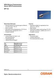
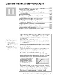
The diagram below (Fig. 1) shows the input voltage (VDC IN) and the primary (IPRI) and secondary (ISEC)<br />
transformer current.<br />
When the CoolMOS Transistor is turned on, the start of all windings on the transformer will go positive.<br />
The rectifier diode (D1) on the secondary side will be reverse-biased and will not conduct. Therefore<br />
no current will flow in the secondary while the CoolMOS Transistor is turned on. During this phase,<br />
energy is being stored in the primary winding inductance and the transformer may be treated as a<br />
simple series inductor. The diagram shows (Fig. 1) that there will be a linear increase of primary<br />
current (IPRI) while the primary CoolMOS Transistor is on.<br />
When the CoolMOS Transistor is turned off, the voltage will reverse on all windings (flyback action)<br />
until clamped by the secondary side widing through the secondary rectifier diode. Now the secondary<br />
rectifier diode (D1) will conduct, and the magnetizing energy in the core will now transfer to the<br />
secondary side during the reset interval.<br />
This current will decrease from it’s peak value to zero, as shown in the diagram (ISEC). In this period<br />
the complete stored energy in the primary inductance will be transferred to the secondary side<br />
(neglecting losses), before the next store cycle starts. The secondary voltage (VSEC) is “reflected” back<br />
(VR) through the transformer turns ratio to the primary winding and added to the input voltage<br />
(VDC IN + VR). Additional transient voltage may appear on the primary winding due to energy stored in<br />
uncoupled “leakage” inductance in the primary winding which isn’t clamped by the secondary side<br />
winding. If the flyback current does not reach zero before the next “on” – Cycle the converter is<br />
operating in continous current mode. When this system reverts to the continous operation, the transfer<br />
function is changed to a two pole system with low output impedance and additional design rules<br />
become important.<br />
SMPS Calculation Software FLYCAL<br />
FLYCAL is an EXCEL spread sheet with all needed Equations for calculating your SMPS easier.<br />
FLYCAL corresponds with the calculating example in this application note, starting at page 5. You only<br />
have to put in the main parameters of your application in FLYCAL and to follow<br />
(like the calculating example in this application note) step by step. FLYCAL contents all used<br />
equations from the example with the same consecutive numbering.<br />
Page 2 of 28 AN-SMPS-1683X – 1<br />
V1.2
Voltage<br />
Current<br />
TDA1683X for OFF – Line Switch Mode <strong>Power</strong> Supplies<br />
Voltage and Current waveforms in discontinous mode operation:<br />
VDC IN min + VR<br />
VDC IN min<br />
IPEAK<br />
IPEAK<br />
Fig. 1<br />
Duty Cycle: D = 0,5 Duty Cycle: D < 0,5<br />
VDC IN = VDC IN min VDC IN > VDC IN min<br />
ISEC<br />
IPRI<br />
0 T<br />
tON<br />
Light load<br />
tOFF<br />
Full load<br />
Duty Cycle:<br />
t<br />
D =<br />
T<br />
VIN + VR<br />
ON<br />
VDC IN<br />
IPEAK IPRI<br />
IPEAK<br />
Page 3 of 28 AN-SMPS-1683X – 1<br />
V1.2<br />
0<br />
ISEC<br />
tON tOFF T
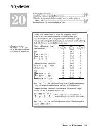
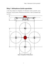
Circuit Diagram:<br />
Fig. 2<br />
TDA1683X for OFF – Line Switch Mode <strong>Power</strong> Supplies<br />
Page 4 of 28 AN-SMPS-1683X – 1<br />
V1.2
TDA1683X for OFF – Line Switch Mode <strong>Power</strong> Supplies<br />
Design Procedure for fixed frequency Flyback Converter with<br />
TDA16831 ... 34 operating in discontinuous current mode.<br />
Define input Parameters:<br />
Procedure Example<br />
Minimal AC input voltage: VAC min<br />
Maximal AC input voltage: VAC max<br />
Line frequency: fAC<br />
Max. Output power: POUT max<br />
Min. Output power: POUT min<br />
Output voltage: VOUT<br />
Output ripple voltage: VOUT Ripple<br />
Reflection voltage: VR<br />
Estimated efficiency: η<br />
DC ripple voltage: VDC IN Ripple<br />
Auxiliary Voltage: VAux<br />
Optocoupler Gain: GC<br />
Used CoolSET<br />
There are no special requirements imposed on the<br />
input rectifier and storage capacitor in the flyback<br />
converter. The components will be selected to meet<br />
the power rating and hold-up requirements.<br />
Maximum input power:<br />
POUT<br />
max<br />
P IN MAX = (Eq 1)<br />
η<br />
Input Diode Bridge (BR1):<br />
P<br />
IN MAX<br />
I PRMS =<br />
(Eq 2)<br />
VAC<br />
min ⋅ cosϕ<br />
V DC max PK = VAC<br />
max ⋅ 2<br />
(Eq 3)<br />
Determine Input Capacitor (C3):<br />
Minimum peak input voltage at ”no load” condition<br />
V DC min PK = VAC<br />
min ⋅ 2<br />
(Eq 4)<br />
85V<br />
270V<br />
50Hz<br />
40W<br />
1W<br />
12V<br />
0,05V<br />
100V<br />
0,8<br />
20V<br />
12V<br />
1<br />
TDA16834 for 40W @ 25°C<br />
PIN MAX<br />
I PRMS<br />
VDC max PK<br />
VDC min PK<br />
40W<br />
= = 50W<br />
0,<br />
8<br />
50W<br />
= = 0,<br />
98<br />
85V<br />
⋅0,<br />
6<br />
= 270V<br />
⋅<br />
=<br />
85V<br />
⋅<br />
Page 5 of 28 AN-SMPS-1683X – 1<br />
V1.2<br />
A<br />
2 = 382V<br />
2 = 120V
V = V min −V<br />
TDA1683X for OFF – Line Switch Mode <strong>Power</strong> Supplies<br />
DC min DC PK Ripple<br />
(Eq 5)<br />
Calculating discharging time at each half line cycle:<br />
V<br />
arcsin<br />
V<br />
= 5ms<br />
⋅ 1+<br />
90<br />
<br />
<br />
DC min<br />
DC min PK<br />
T D<br />
(Eq 6)<br />
Required energy at discharging time of C3:<br />
W P ⋅T<br />
IN<br />
= (Eq 7)<br />
IN MAX<br />
D<br />
Calculating input capacitor value CIN:<br />
C<br />
IN<br />
V<br />
2 ⋅W<br />
= (Eq 8)<br />
2<br />
DC min PK<br />
IN<br />
2<br />
VDC<br />
min<br />
−<br />
Alternative a rule of thumb on choosing CIN:<br />
Input voltage CIN<br />
115V 2µF/W<br />
230V 1µF/W<br />
85V ...270V 2 ...3µF/W....................<br />
Postcalculation of input Capacitore:<br />
Select a capacitor out of Epcos Databook<br />
of Aluminium Electrolytic Capacitors.<br />
The following types are preferred:<br />
For 85°C Applications:<br />
Series B43303-........ 2000h lifetime<br />
B43501-........ 10000h lifetime<br />
For 105°C Applications:<br />
Series B43504-........ 3000h lifetime<br />
B43505-........ 5000h lifetime<br />
V<br />
DC<br />
=<br />
V<br />
2<br />
DC min PK<br />
2 ⋅W<br />
−<br />
C<br />
min (Eq 9)<br />
IN<br />
IN<br />
<br />
we choose a ripple voltage of 20V<br />
VDC min<br />
T D<br />
W IN<br />
= 120V<br />
− 20V<br />
= 100V<br />
100V<br />
<br />
arcsin<br />
= 5 ms • 1+<br />
120V<br />
= 8,<br />
1ms<br />
90<br />
<br />
<br />
= 50 W ⋅8,<br />
1ms<br />
= 0,<br />
41Ws<br />
2⋅<br />
0,<br />
41Ws<br />
CIN =<br />
= 185µ<br />
F<br />
2<br />
2<br />
14400V<br />
−10000V<br />
µ F<br />
50 W ⋅3<br />
= 150µ<br />
F<br />
W<br />
We choose 180µF 400V (based on Eq 8)<br />
VDC min<br />
=<br />
2 0,<br />
41Ws<br />
14400V 99,<br />
2V<br />
180 F<br />
2 ⋅<br />
− =<br />
µ<br />
Page 6 of 28 AN-SMPS-1683X – 1<br />
V1.2
Transformer Design (TR1):<br />
TDA1683X for OFF – Line Switch Mode <strong>Power</strong> Supplies<br />
Calculation of peak current on primary inductance:<br />
I<br />
2 ⋅ PIN<br />
V ⋅ D<br />
LPK =<br />
MAX<br />
(Eq 10)<br />
DC min max<br />
Dmax<br />
= I ⋅<br />
(Eq 11)<br />
3<br />
I LRMS LPK<br />
Calculating of primary inductance within limit of<br />
maximum Duty-Cycle :<br />
L<br />
P<br />
=<br />
D<br />
max<br />
I<br />
⋅V<br />
LPK<br />
DC min<br />
⋅ f<br />
Select core type and inductance factor (AL) from<br />
Epcos ferrite Databook or CD-ROM<br />
Passive Components.<br />
(Eq 12)<br />
Fix maximum flux density:<br />
Bmax ≈ 0,2T ...0,3T for ferrite cores depending on core<br />
material.<br />
We choose 0,2T for material N27<br />
The primary turns can be calculated as:<br />
L<br />
P<br />
N P = (Eq 13)<br />
AL<br />
Number of secondary turns can be calculated as:<br />
( V + V )<br />
N P ⋅ OUT FDIODE<br />
Ns = (Eq 14)<br />
V<br />
R<br />
Dmax = 0,5 (see datasheet TDA16834)<br />
I LPK<br />
I LRMS<br />
L P<br />
2 ⋅ 50W<br />
= = 2,<br />
02<br />
99,<br />
2V<br />
⋅ 0,<br />
5<br />
Page 7 of 28 AN-SMPS-1683X – 1<br />
V1.2<br />
A<br />
0,<br />
5<br />
= 2 , 02A<br />
⋅ = 0,<br />
83<br />
3<br />
0,<br />
5 ⋅99,<br />
2V<br />
=<br />
= 246µ<br />
H<br />
3<br />
2,<br />
02A<br />
⋅100*<br />
10 Hz<br />
Selected core: E 32/16/9<br />
Material = N27<br />
AL = 244 nH<br />
s = 0,5 mm<br />
Ae = 83 mm 2<br />
AN = 108,5 mm 2<br />
lN = 64,4 mm<br />
weight ≈ 30g<br />
PV = 190mW/g (200mT, 100kHz, 100°C)<br />
N P<br />
=<br />
246µ<br />
H<br />
244nH<br />
=<br />
31,<br />
75<br />
we choose Np = 32 turns<br />
32 ⋅<br />
Ns =<br />
( 12V<br />
+ 0,<br />
7V<br />
)<br />
100V<br />
we choose NS = 4 turns<br />
=<br />
A<br />
turns<br />
4,<br />
06
TDA1683X for OFF – Line Switch Mode <strong>Power</strong> Supplies<br />
Number of auxiliary turns can be calculated as:<br />
N<br />
N<br />
⋅<br />
( V + V )<br />
P Aux FDIODE<br />
Aux = (Eq 15)<br />
VR<br />
Postcalculation of primary inductance, primary peak<br />
current, max. flux density and gap:<br />
P<br />
2<br />
P<br />
L = N ⋅ A<br />
I<br />
LPK<br />
V<br />
=<br />
l<br />
DC min<br />
P<br />
⋅ D<br />
Lp ⋅ f<br />
e<br />
max<br />
(Eq 16)<br />
(Eq 17)<br />
LP<br />
⋅ I LPK<br />
Bmax<br />
=<br />
(Eq 18)<br />
N ⋅ A<br />
4⋅π ⋅10<br />
s =<br />
L<br />
−7 2<br />
⋅ N P<br />
P<br />
⋅ A<br />
Winding Design:<br />
(see also page 21<br />
Transformer Construction)<br />
e<br />
(Eq 19)<br />
The primary winding of 32 turns has to be split into<br />
16+16 turns in order to get best coupling between<br />
primary and secondary winding.<br />
The effective bobbin width and winding cross section<br />
can be calculated:<br />
BW e<br />
A<br />
Ne<br />
= BW − 2 ⋅ M<br />
(Eq 20)<br />
AN<br />
⋅ BWe<br />
= (Eq 21)<br />
BW<br />
Calculate copper section for primary and secondary<br />
winding:<br />
The winding cross section AN has to be splitted into<br />
the number of windings.<br />
Primary winding 0,5<br />
Secondary winding 0,45<br />
Auxiliary winding 0,05<br />
N Aux<br />
32 ⋅<br />
=<br />
( 12V<br />
+ 0,<br />
7V<br />
)<br />
100V<br />
we choose NAux = 4 turns<br />
L P<br />
I LPK<br />
=<br />
32 2<br />
4,<br />
06<br />
Page 8 of 28 AN-SMPS-1683X – 1<br />
V1.2<br />
=<br />
⋅ 244nH<br />
= 250µ<br />
H<br />
99,<br />
2V<br />
⋅ 0,<br />
5<br />
=<br />
250µ<br />
H ⋅100*<br />
10<br />
3<br />
Hz<br />
250µ<br />
H ⋅1,<br />
98A<br />
Bmax =<br />
= 186mT<br />
2<br />
32 ⋅83mm<br />
= 1,<br />
98A<br />
−7<br />
2<br />
2<br />
4 ⋅π<br />
⋅10<br />
⋅ 32 ⋅83mm<br />
s =<br />
= 0,<br />
43mm<br />
250µ<br />
H<br />
From bobbin datasheet E32/16/9: BW = 20,1mm<br />
Margin determined: M = 4mm<br />
BW e<br />
=<br />
20 , 1mm<br />
− 2⋅<br />
4mm<br />
= 12,<br />
1mm
Copper space factor fCu :0,2 ....0,4<br />
A<br />
P<br />
⋅ AN<br />
=<br />
N<br />
5 , 0<br />
⋅ f<br />
P<br />
Cu<br />
⋅ BW<br />
⋅ BW<br />
( 1,<br />
8277 − ( 2 ( d ) ) )<br />
e<br />
TDA1683X for OFF – Line Switch Mode <strong>Power</strong> Supplies<br />
(Eq 22)<br />
AWG = 9, 97 ⋅ ⋅log<br />
(Eq 23)<br />
A<br />
A<br />
s<br />
aux<br />
⋅ A<br />
=<br />
N<br />
45 , 0<br />
N<br />
s<br />
⋅ A<br />
=<br />
N<br />
05 , 0<br />
⋅ f<br />
Cu<br />
⋅ BW<br />
N<br />
aux<br />
⋅ f<br />
⋅ BW<br />
Cu<br />
⋅ BW<br />
e<br />
⋅ BW<br />
e<br />
(Eq 24)<br />
(Eq 25)<br />
With the effective bobbin width we check the number<br />
of turns per layer:<br />
BWe<br />
N P = (Eq 26)<br />
d<br />
P<br />
We calculate the available area for each winding:<br />
Used for calculation: fCu =0,3<br />
A P<br />
A s<br />
A aux<br />
=<br />
=<br />
0,<br />
5<br />
⋅<br />
2<br />
108,<br />
5mm<br />
⋅<br />
32 ⋅ 20,<br />
1<br />
12,<br />
1<br />
= 0,<br />
31mm<br />
Page 9 of 28 AN-SMPS-1683X – 1<br />
V1.2<br />
0<br />
, 3<br />
diameter dp ≈ 0,64mm 22 AWG<br />
0,<br />
45<br />
Primary:<br />
N P<br />
⋅<br />
2<br />
108,<br />
5mm<br />
4 ⋅ 20,<br />
1<br />
⋅<br />
⋅<br />
0,<br />
3<br />
⋅<br />
12,<br />
1<br />
2<br />
= 2,<br />
20mm<br />
diameter ds 2 x 0,8mm 2 x 20 AWG<br />
2<br />
0,<br />
05⋅108,<br />
5mm<br />
⋅0,<br />
3⋅12,<br />
1<br />
2<br />
=<br />
= 0,<br />
24mm<br />
4⋅<br />
20,<br />
1<br />
diameter da ≈ 0,64mm 22 AWG<br />
12,<br />
1mm<br />
= = 17 turns per layer<br />
0,<br />
64mm<br />
Secondary:<br />
2 layer needed<br />
12,<br />
1mm<br />
N S = = 4 turns per layer<br />
2⋅<br />
0,<br />
8mm<br />
Auxiliary:<br />
Can be neglected !<br />
2
Output Rectifier (D1):<br />
TDA1683X for OFF – Line Switch Mode <strong>Power</strong> Supplies<br />
The output rectifier diodes in flyback converters are<br />
subject to a large PEAK and RMS current stress. The<br />
values depend on the load, leakage inductance,<br />
operating mode and output capacitor ESR.<br />
Calculation of the maximum reverse voltage:<br />
<br />
+ <br />
V<br />
<br />
N<br />
⋅<br />
N<br />
VRDiode = VOUT<br />
DC max PK<br />
S<br />
P<br />
(Eq 27)<br />
Calculation of the maximum current on secondary<br />
side:<br />
N<br />
I ⋅<br />
P<br />
SPK = I LPK<br />
(Eq 28)<br />
N S<br />
= I ⋅ 1 ⋅ D<br />
3 max<br />
(Eq 29)<br />
I SRMS SPK<br />
Output Capacitors (C5 & C9):<br />
Output capacitors are highly stressed in flyback<br />
converters. Normally the capacitor will be selected for<br />
3 major parameters: capacitance value, low ESR<br />
and ripple current rating.<br />
Max. voltage overshoot: ∆VOUT<br />
Number of clock periods: nCP<br />
C<br />
OUT<br />
=<br />
I<br />
∆V<br />
OUT<br />
⋅<br />
⋅ f<br />
OUT max n CP<br />
Select a capacitor out of Epcos Databook<br />
of Aluminium Electrolytic Capacitors.<br />
The following types are preferred:<br />
For 85°C Applications:<br />
Series B41826-........ 2000h lifetime<br />
For 105°C Applications:<br />
Series B41856-........ 2000h lifetime<br />
<br />
(Eq 30)<br />
V RDiode<br />
I SPK<br />
I SRMS<br />
4 <br />
= 12 V + 382V<br />
⋅ = 59,<br />
8V<br />
32<br />
32<br />
= 1 , 98A<br />
⋅ = 15,<br />
8A<br />
4<br />
= 15 , 8A<br />
⋅ 1 ⋅ 0,<br />
5 = 6,<br />
5<br />
3<br />
To calculate the output capacitor, it is necessary to fix<br />
the maximum voltage overshoot in case of switching<br />
off @ maximum load condition.<br />
After switching off the load, the regulation loop needs<br />
about 5...10 periods of internal clock to reduce the<br />
duty cycle.<br />
∆<br />
V OUT<br />
nCP = 5<br />
C OUT<br />
= 0,<br />
5V<br />
3,<br />
33A<br />
⋅ 5<br />
=<br />
= 333µ<br />
F<br />
3<br />
0,<br />
5V<br />
⋅100<br />
* 10 Hz<br />
We select 470µF 25V (based on Eq 30):<br />
B41826-A5477-M<br />
ESR ≈ Zmax = 0,06Ω @ 100kHz<br />
IacR = 2,2A<br />
ISRMS = 6,6A (Eq 29) you need 3 capacitor<br />
Page 10 of 28 AN-SMPS-1683X – 1<br />
V1.2<br />
A
Output Filter (L3 & C9):<br />
TDA1683X for OFF – Line Switch Mode <strong>Power</strong> Supplies<br />
The output filter consists of one capacitor (C9) and<br />
one inductor (L3) in a L-C filter topology.<br />
Zero frequency of output capacitor (C9) and<br />
associated ESR:<br />
f<br />
ZCOUT<br />
1<br />
=<br />
2 ⋅π<br />
⋅ R<br />
ESR<br />
⋅ C<br />
OUT<br />
(Eq 31)<br />
Calculating the needed inductance (L3) for substitute<br />
the zero of the 3 output capacitors:<br />
L<br />
OUT<br />
R<br />
=<br />
2 ⋅π<br />
⋅ f<br />
VCC – Supply:<br />
ESR<br />
ZCOUT<br />
⋅ n<br />
pCOUT<br />
Start-up Resistor (R6 & R7):<br />
ICCLmax = max. Quiescent Current (Control IC)<br />
ILoadC = VCC-Capacitor Load-Current (C4)<br />
CVCC = Value of VCC-Capacitor (C4)<br />
R<br />
Start<br />
=<br />
I<br />
V<br />
CCL max<br />
DC min<br />
Start up Time tStart:<br />
t<br />
C<br />
⋅V<br />
+ I<br />
LoadC<br />
(Eq 32)<br />
(Eq 33)<br />
VCC CCH<br />
Start = (Eq 34)<br />
I LoadC<br />
Internal Zener Diode:<br />
Depending on the transformer construction and load<br />
condition the auxiliary supply voltage varies within an<br />
operating range. If VCC exceeds VZ (16V), the<br />
internal zener diode conducts. In this case we have<br />
to observe the internal power dissipation limits or<br />
use an external zener diode on VCC pin.<br />
f ZCOUT<br />
L OUT<br />
1<br />
=<br />
= 5,<br />
6kHz<br />
2⋅π<br />
⋅0,<br />
06Ω<br />
⋅ 470µ<br />
F<br />
0,<br />
06Ω<br />
=<br />
= 0,<br />
57µ<br />
H<br />
2 ⋅π<br />
⋅ 5,<br />
6kHz<br />
⋅3<br />
ICCLmax = 80µA<br />
ILoadC = 40µA<br />
CVCC = 22µF<br />
R Start<br />
99,<br />
2V<br />
= = 827kΩ<br />
( 80 + 40)<br />
µ A<br />
R6 = R7 =1/2 RStart = 413,5kΩ<br />
Choose 2 with value: 410kΩ<br />
t Sstart<br />
22µ<br />
F ⋅12V<br />
=<br />
= 6,<br />
6s<br />
40µ<br />
A<br />
Note:<br />
Before the IC can be plugged into the application<br />
board, the VCC capacitor has always to be<br />
discharged!<br />
Page 11 of 28 AN-SMPS-1683X – 1<br />
V1.2
Calculation of Snubber Network:<br />
(R10/C12/D3)<br />
V = V −V<br />
max −V<br />
Snub<br />
BR)<br />
DSS<br />
DC<br />
TDA1683X for OFF – Line Switch Mode <strong>Power</strong> Supplies<br />
R<br />
( (Eq 35)<br />
For calculating the snubber network it is neccesary to<br />
know the leakage inductance. Most common way is<br />
to have the value of the leakage inductance (LLK) in<br />
percent of the primary inductance (Lp). If it is known<br />
that the transformer construction is very consistent,<br />
measuring the primary leakage inductance by<br />
shorting the secondary windings will give an exact<br />
number, assuming the availability of a good LCR<br />
analyser.<br />
L LK<br />
C<br />
R<br />
Snub<br />
Snub<br />
= Lp ⋅ x%<br />
=<br />
I<br />
2<br />
LPK<br />
⋅ L<br />
LK<br />
( VR<br />
+ VSsnub<br />
) ⋅VSnub<br />
( V + V )<br />
2<br />
Ssnub R −V<br />
R<br />
= 2<br />
0,<br />
5 ⋅ L ⋅ I ⋅ f<br />
LK<br />
2<br />
LPK<br />
(Eq 36)<br />
(Eq 37)<br />
V Snub<br />
= 650 V − 382V<br />
−100V<br />
= 168V<br />
In our example we choose 5% of primary inductance<br />
for leakage inductance.<br />
L LK<br />
C Ssnub<br />
R Snub<br />
= 250 µ H ⋅5%<br />
= 12,<br />
5µ<br />
H<br />
=<br />
( 1,<br />
98A)<br />
( 100V<br />
+ 168V<br />
)<br />
⋅12,<br />
5µ<br />
H<br />
= 1,<br />
1nF<br />
⋅168V<br />
Page 12 of 28 AN-SMPS-1683X – 1<br />
V1.2<br />
2<br />
( 168V<br />
+ 100V<br />
)<br />
2<br />
≈ 1,2nF<br />
2<br />
−100V<br />
= = 25,<br />
3kΩ<br />
2<br />
3<br />
0,<br />
5⋅12,<br />
5µ<br />
H ⋅ ( 1,<br />
98A)<br />
⋅100*<br />
10 Hz<br />
≈25kΩ
Calculation of Losses:<br />
Input diode bridge (BR1):<br />
TDA1683X for OFF – Line Switch Mode <strong>Power</strong> Supplies<br />
P DIN = I PRMS ⋅VF<br />
⋅ 2<br />
(Eq 38)<br />
Calculation of copper resistance RCu:<br />
R<br />
l<br />
⋅ N<br />
⋅ p<br />
N P 100<br />
PCu = (Eq 39)<br />
AP<br />
Calculating of copper loss (TR1):<br />
2<br />
PCu = I LPK ⋅ DMAX<br />
⋅ 1 ⋅ R<br />
3<br />
Output rectifier diode (D1):<br />
Cu<br />
1 − Dmax<br />
PDDIODE = I SPK ⋅ ⋅V<br />
3<br />
COOLMOS TRANSISTOR:<br />
TDA16834<br />
Calculated @ VDCmin = 99V<br />
CO ≈ 50pF (CO = COSS + CExtern)<br />
RDSON = 1,6Ω (@ 150°C)<br />
Switching losses:<br />
2<br />
PSON = ⋅C<br />
O ⋅V<br />
2<br />
DC<br />
min<br />
⋅ f<br />
FDIODE<br />
(Eq 40)<br />
(Eq 41)<br />
1 (Eq 42)<br />
( VDC<br />
+ VR<br />
) ⋅ I LPK ⋅ f tr<br />
1 (Eq 43)<br />
PSOFF = ⋅ min<br />
⋅<br />
6<br />
Conduction losses:<br />
2<br />
P 1<br />
D ⋅ RDSON<br />
⋅ I LPK ⋅ Dmax<br />
= (Eq 44)<br />
3<br />
P DIN<br />
= 0 , 98A<br />
⋅1V<br />
⋅ 2 = 1,<br />
96W<br />
Copper resistivity p100 @ 100°C = 0,0172Ωmm 2 /m<br />
R PCu<br />
R SCu<br />
P PCu<br />
P SCu<br />
2<br />
0,<br />
0644m<br />
⋅32<br />
⋅17,<br />
2mΩmm<br />
/ m<br />
= = 114,<br />
3mΩ<br />
2<br />
0,<br />
31mm<br />
2<br />
0,<br />
0644m<br />
⋅ 4 ⋅17,<br />
2mΩmm<br />
/ m<br />
= = 2,<br />
01mΩ<br />
2<br />
2,<br />
20mm<br />
2<br />
= ( 1,<br />
98A)<br />
⋅ 0,<br />
5⋅<br />
1 ⋅114,<br />
3mΩ<br />
= 74,<br />
7mW<br />
3<br />
2<br />
= ( 15,<br />
8A)<br />
⋅ 0,<br />
5 ⋅ 1 ⋅ 2,<br />
01mΩ<br />
= 84,<br />
1mW<br />
3<br />
P Cu<br />
P DDIODE<br />
= 74,<br />
7mW<br />
+ 84,<br />
1mW<br />
= 158,<br />
8mW<br />
1−<br />
0,<br />
5<br />
= 15 , 8A<br />
⋅ ⋅ 0,<br />
7V<br />
= 4,<br />
52W<br />
3<br />
(see also TDA 16831 ... 34 Data Sheet)<br />
P SON<br />
P SOFF<br />
P D<br />
=<br />
=<br />
1<br />
2<br />
⋅ 50 pF ⋅99V<br />
Page 13 of 28 AN-SMPS-1683X – 1<br />
V1.2<br />
2<br />
3<br />
⋅100<br />
* 10 Hz = 24,<br />
5mW<br />
( 99V<br />
+ 100V<br />
) ⋅ 2,<br />
02A<br />
⋅100kHz<br />
⋅30ns<br />
197mW<br />
= 1 ⋅<br />
=<br />
6<br />
1<br />
3<br />
2<br />
⋅1,<br />
6Ω<br />
⋅ ( 1,<br />
98A)<br />
⋅ 0,<br />
5 = 1,<br />
05W
Summary of Losses:<br />
P P + P + P<br />
Losses<br />
SON<br />
SOFF<br />
TDA1683X for OFF – Line Switch Mode <strong>Power</strong> Supplies<br />
= (Eq 44a)<br />
Thermal Calculation:<br />
K<br />
Table of typical thermal Resistance [ ]:<br />
W<br />
Heatsink DIP8 SO14<br />
No 90 112<br />
3 cm² 64 92<br />
6 cm² 56 78<br />
dT P * R<br />
Losses<br />
th<br />
D<br />
= (Eq 44b)<br />
Tj dT + Ta<br />
= (Eq 44c)<br />
P Losses<br />
= 25 , 4mW<br />
+ 197mW<br />
+ 1005mW<br />
= 1,<br />
27W<br />
K<br />
dT = 1 , 27W<br />
* 56 = 71,<br />
2K<br />
W<br />
Tj = 71,<br />
2K<br />
+ 50°<br />
C = 121°<br />
C<br />
Page 14 of 28 AN-SMPS-1683X – 1<br />
V1.2
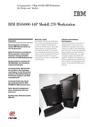
Voltage Regulation Loop:<br />
Reference: TL431 (IC2)<br />
VREF =2,5V<br />
IKAmin=1mA<br />
Optocoupler: SFH617-3 (IC1)<br />
Gc = 1 ...2 ≡ CTR 100% ...200%<br />
VFD = 1,2V<br />
IFmax =10mA (maximum current limit)<br />
Primary side:<br />
Feedback voltage:<br />
Values from TDA16831...34 datasheet<br />
VRef int = 5.5V typ.<br />
VFBmax = 4,8V<br />
RFB = 3,7k typ.<br />
I<br />
I<br />
FB<br />
V<br />
R<br />
Re f int<br />
FB<br />
TDA1683X for OFF – Line Switch Mode <strong>Power</strong> Supplies<br />
max = (Eq 45)<br />
FB min<br />
V<br />
Re f int<br />
−V<br />
R<br />
FB<br />
FB max<br />
= (Eq 46)<br />
Secondary side:<br />
1<br />
VOUT<br />
<br />
= R <br />
2 −1<br />
VREF<br />
R (Eq 47)<br />
the value of R2 can be fixed at 4,7k<br />
R<br />
R<br />
( V − ( V + V ) )<br />
OUT FD REF<br />
3 ≥ (Eq 48)<br />
I F max<br />
4<br />
V<br />
FD<br />
<br />
+ R<br />
<br />
I<br />
3<br />
KA min<br />
I<br />
⋅<br />
Gc<br />
FB min<br />
<br />
≤ (Eq 49)<br />
Fig. 3<br />
Fig. 4<br />
I FB max<br />
I FB min<br />
5,5V<br />
3,7k<br />
VFB<br />
R3<br />
TL431<br />
5,<br />
5V<br />
= = 1,<br />
5mA<br />
3,<br />
7kΩ<br />
5,<br />
5V<br />
− 4,<br />
8V<br />
=<br />
= 0,<br />
19mA<br />
3,<br />
7kΩ<br />
12V<br />
<br />
R1 = 4,<br />
7k<br />
⋅<br />
−1<br />
= 17,<br />
86k<br />
2,<br />
5V<br />
( 12V<br />
− ( 1,<br />
2V<br />
+ 2,<br />
5V<br />
) )<br />
R3 = 0,<br />
83k<br />
10mA<br />
≥ ≈ 910R<br />
0,<br />
2mA<br />
<br />
1,<br />
2V<br />
+ 910R<br />
⋅<br />
1<br />
R4 = 1,<br />
4k<br />
1mA<br />
≤ ≈ 1,2k<br />
Page 15 of 28 AN-SMPS-1683X – 1<br />
V1.2<br />
FB<br />
R4<br />
R5<br />
C2<br />
C1<br />
R1<br />
R2<br />
Vout
Regulation Loop:<br />
Fig. 5<br />
TDA1683X for OFF – Line Switch Mode <strong>Power</strong> Supplies<br />
Transfer Characteristics of Regulation Loop Elements:<br />
K<br />
G<br />
⋅ 3k7<br />
C<br />
FB = Feedback<br />
R3<br />
R2<br />
V<br />
K VD = =<br />
R1<br />
+ R2<br />
V<br />
F<br />
F<br />
PWR<br />
LC<br />
VIN<br />
1<br />
( p)<br />
=<br />
Z<br />
( p)<br />
PWM<br />
⋅<br />
REF<br />
OUT<br />
<br />
<br />
LP<br />
⋅ f ⋅η<br />
RL<br />
⋅ <br />
2 ⋅ RL<br />
R<br />
<br />
1<br />
+ p ⋅ <br />
2<br />
ZPWM = Transimpedance ∆VFB/∆ID<br />
1 + p ⋅ R<br />
FPWR(p)<br />
KFB<br />
⋅ C<br />
( 1 + p ⋅ R ⋅ C )<br />
L<br />
ESR<br />
+ R<br />
ESR<br />
<br />
⋅<br />
5<br />
C<br />
5<br />
<br />
<br />
<br />
Voltage Divider<br />
Page 16 of 28 AN-SMPS-1683X – 1<br />
V1.2<br />
<br />
<strong>Power</strong> stage<br />
ESR 9<br />
= Output filter<br />
2<br />
1 + p ⋅ RESR<br />
⋅ C9<br />
+ p ⋅ L ⋅ C9<br />
( C1+<br />
C2)<br />
FLC(p)<br />
Fr(p)<br />
1+<br />
p ⋅ R5⋅<br />
Fr(<br />
p)<br />
= Regulator<br />
R1⋅<br />
R2<br />
p ⋅ ⋅C1⋅<br />
( 1+<br />
p ⋅ R5⋅<br />
C2)<br />
R1+<br />
R2<br />
KVD<br />
_<br />
+<br />
Vout<br />
Vref
TDA1683X for OFF – Line Switch Mode <strong>Power</strong> Supplies<br />
Zero’s and Poles of the transfer characteristics:<br />
Poles of powerstage @ min. and max. load:<br />
2<br />
12<br />
= = = 3,<br />
6Ω<br />
40<br />
2<br />
VOUT<br />
V<br />
12<br />
RLH<br />
= = = 144Ω<br />
P W<br />
1<br />
2<br />
VOUT<br />
V<br />
RLL<br />
P W<br />
f<br />
f<br />
OH<br />
OL<br />
=<br />
π ⋅<br />
=<br />
π ⋅<br />
OUT max<br />
1<br />
R ⋅ C5<br />
LH<br />
1<br />
R ⋅ C5<br />
LL<br />
f OH<br />
f OL<br />
2<br />
OUT min<br />
1<br />
=<br />
=<br />
π ⋅ 3,<br />
6Ω<br />
⋅1410µ<br />
F<br />
62,<br />
7<br />
Hz<br />
1<br />
=<br />
= 1,<br />
57Hz<br />
π ⋅144Ω<br />
⋅1410µ<br />
F<br />
The gain (Gc) of the optocoupler stage KFB and the voltage divider KVD we use as a constant.<br />
K<br />
G<br />
⋅ 3k7<br />
C<br />
FB = KFB = 6,6 GFB = 16,4db<br />
R3<br />
R2<br />
V<br />
K VD = =<br />
R1<br />
+ R2<br />
V<br />
REF<br />
OUT<br />
KVD = 0,208 GVD = -13,6db<br />
With adjustment of the transfer characteristics of the regulator we want to have equal gain within the<br />
operating range and to compensate the pole fo of the powerstage FPWR(ω).<br />
Because of the compensation of the output capacitors zero (see page 11 Eq31, Eq32) we neglect this zero<br />
and the LC-Filter pole.<br />
So the transfer characteristics of the power stage is reduced to a single pole response.<br />
In order to calculate the gain of the open loop we have to select the crossover frequency.<br />
We calculate the gain of the <strong>Power</strong>-Stage with max. output power at the selected crossover frequency<br />
fg = 3kHz:<br />
ZPWM of TDA16834 =1,3 V/A<br />
PWM<br />
( t )<br />
ON<br />
= Z<br />
PWM<br />
⋅<br />
t<br />
<br />
⋅ t<br />
<br />
<br />
+ 0,<br />
6 ⋅ − e<br />
<br />
1<br />
ON<br />
−tON<br />
T1<br />
ON − T1<br />
+ T1⋅<br />
e<br />
1<br />
−tON<br />
T 2<br />
Z (formula according data sheet p. 12)<br />
<br />
Page 17 of 28 AN-SMPS-1683X – 1<br />
V1.2
TDA1683X for OFF – Line Switch Mode <strong>Power</strong> Supplies<br />
with this formula we calculate ZPWM @ max. duty cycle:<br />
Z<br />
PWM<br />
( t )<br />
ON<br />
V 1 <br />
= 1,<br />
3 ⋅ ⋅ 4,<br />
7µ<br />
s − 850ns<br />
+ 850ns<br />
⋅ e<br />
A 4,<br />
7µ<br />
s <br />
Gain @ crossover frequency:<br />
F<br />
PWR<br />
F PWR<br />
1<br />
( fg)<br />
=<br />
Z<br />
( 3kHz)<br />
=<br />
PWM<br />
1<br />
1,<br />
7<br />
⋅<br />
⋅<br />
R<br />
GPWR(3kHz) = -22,7db<br />
Transfer characteristics:<br />
Fig. 6<br />
L<br />
<br />
<br />
⋅ L <br />
p ⋅ f ⋅η<br />
⋅ <br />
2 <br />
<br />
<br />
<br />
1<br />
fg <br />
1 + <br />
<br />
<br />
<br />
fo<br />
<br />
<br />
3,<br />
6R<br />
⋅ 250µ<br />
H ⋅100kHz<br />
⋅ 0,<br />
8 <br />
⋅ <br />
2<br />
<br />
<br />
<br />
<br />
Gain<br />
[db]<br />
50<br />
G<br />
PWR<br />
( ω )<br />
Gr( ω )<br />
G FB<br />
G MOD<br />
0<br />
50<br />
50<br />
0<br />
GVD<br />
Gr(ω)<br />
2<br />
<br />
<br />
+ 0,<br />
6 ⋅ 1<br />
− e<br />
<br />
− 4,<br />
7µ<br />
s<br />
−4,<br />
7µ<br />
s<br />
850ns<br />
200ns<br />
1<br />
3000 <br />
1+<br />
<br />
62,<br />
7<br />
1 10 100 1 10 3<br />
50<br />
1 ω( ) i<br />
2. π<br />
2<br />
<br />
=<br />
1 10 4<br />
0,<br />
073<br />
GFB<br />
GPWR(ω)<br />
1 10 5<br />
110 . 5<br />
V<br />
= 1,<br />
7<br />
A<br />
Page 18 of 28 AN-SMPS-1683X – 1<br />
V1.2
TDA1683X for OFF – Line Switch Mode <strong>Power</strong> Supplies<br />
At the crossover frequency (fg) we calculate for the open loop gain:<br />
Gol(ω) = Gs (ω) + Gr (ω) = 0.<br />
With the equations of the transfer characteristics we calculate the gain of the regulation loop @ fg.<br />
The gain of the regulation loop we calculate:<br />
Gs = GFB + GPWR + GVD = 16,4db – 22,7db – 13,6db<br />
Gs = -19,9db<br />
We calculate the separate components of the regulator:<br />
Gs (ω) + Gr (ω) = 0 Gr = 0 – (-19,9db) = 19,9db<br />
( C1+<br />
C2)<br />
)<br />
1+<br />
p ⋅ R5⋅<br />
Fr(<br />
p)<br />
=<br />
R1⋅<br />
R2<br />
p ⋅ ⋅C1⋅<br />
( 1+<br />
p ⋅ R5⋅<br />
C2)<br />
R1+<br />
R2<br />
( R1<br />
+ R2)<br />
R5⋅<br />
Gr = 20⋅<br />
log<br />
R1⋅<br />
R2<br />
1<br />
fp =<br />
2⋅π<br />
⋅ R5⋅<br />
C2<br />
20,<br />
9<br />
R5<br />
= 10<br />
Gr<br />
20<br />
20 R5 10 ⋅3,<br />
72k<br />
= 41,<br />
7k<br />
R1⋅<br />
R2<br />
⋅<br />
R1+<br />
R2<br />
= ≈ 43k<br />
1<br />
C2<br />
=<br />
2⋅π<br />
⋅ R5⋅<br />
2⋅<br />
fg<br />
1<br />
C2 =<br />
= 617 pF<br />
2⋅π<br />
⋅ 43k<br />
⋅6kHz<br />
≈ 680pF<br />
fp = 2*fg<br />
In order to have enough phase margin @ low load condition we select the zero frequency of compensation<br />
network at the middle between min. and max. load pole of power stage.<br />
f<br />
om<br />
oh<br />
fol<br />
0,<br />
5 log<br />
foh<br />
10 ⋅<br />
62,<br />
7<br />
= f ⋅<br />
= 62,<br />
7Hz<br />
⋅10<br />
= 9,<br />
92Hz<br />
1<br />
fz =<br />
2⋅π<br />
⋅ R5⋅<br />
( C1+<br />
C2)<br />
f om<br />
1,<br />
57<br />
0,<br />
5⋅log<br />
1<br />
C1 =<br />
− C2<br />
2⋅π<br />
⋅ R5⋅<br />
fom<br />
1<br />
C1 =<br />
− 680 pF = 384nF<br />
2⋅π<br />
⋅ 43k<br />
⋅9,<br />
92Hz<br />
≈ 390nF<br />
Page 19 of 28 AN-SMPS-1683X – 1<br />
V1.2
Open Loop Gain<br />
Fig. 7<br />
Open Loop Phase<br />
Fig. 8<br />
TDA1683X for OFF – Line Switch Mode <strong>Power</strong> Supplies<br />
70<br />
Gr( ω )<br />
Gs( ω )<br />
G( ω )<br />
0<br />
10<br />
φr( ω )<br />
φs( ω )<br />
φ( ω )<br />
0<br />
180<br />
60<br />
50<br />
0<br />
50<br />
10<br />
28<br />
66<br />
104<br />
142<br />
1 10 100 1 10 3<br />
1 ω( ) i<br />
2. π<br />
1 10 100 1 10 3<br />
180<br />
1 ω( ) i<br />
2. π<br />
1 10 4<br />
1 10 4<br />
1 10 5<br />
110 . 5<br />
1 10 5<br />
110 . 5<br />
Page 20 of 28 AN-SMPS-1683X – 1<br />
V1.2
Transformer Construction<br />
TDA1683X for OFF – Line Switch Mode <strong>Power</strong> Supplies<br />
The winding topology has a considerable influence on the performance and relaibility of the<br />
transformer.<br />
To reduce leakage inductance and proximity to acceptable limits, the use of a sandwich construction is<br />
recommended.<br />
In order to meet international safety requirements a transformer for Off - Line power supply must have<br />
adequate insulation between primary and secondary winding.<br />
This can be achived by using a margin wound construction or using triple insulated wire for the<br />
secondary winding.<br />
The creepage distance for universal input voltage range is typically 8mm. This sets a minimum margin<br />
width as a half of the creepage distance to 4mm. Additional the neccesary insulation between primary<br />
and secondary winding is provided using three layers of basic insulation tape.<br />
Example of winding topology for margin wound transformers:<br />
Fig. 9<br />
Example of winding topology with triple insulated wire for secondary winding:<br />
Fig. 10<br />
Triple Insulated<br />
Wire<br />
BW* : value from bobbin datasheet<br />
Creepage<br />
distance<br />
Triple insulation<br />
BW*<br />
BWe<br />
margin margin<br />
BW*<br />
Primary<br />
second half<br />
Secondary<br />
Auxiliary<br />
Primary<br />
first half<br />
Primary<br />
second half<br />
Secondary<br />
Auxiliary<br />
Primary<br />
first half<br />
Page 21 of 28 AN-SMPS-1683X – 1<br />
V1.2
Layout Recommendation:<br />
Fig. 11<br />
TDA1683X for OFF – Line Switch Mode <strong>Power</strong> Supplies<br />
In order to avoid crosstalk between <strong>Power</strong>- and Signal-Path on the board we have to use care<br />
regarding the track layout when designing the PCB.<br />
The <strong>Power</strong>-Path (see Fig. 11) has to be as short as possible and separated from the VCC-Path and<br />
the Feedback-Path. All GND-Paths have to be connected together at pin 8 (star ground) (1 and 14 at<br />
G-type) of TDA16831...34.<br />
Page 22 of 28 AN-SMPS-1683X – 1<br />
V1.2
Output <strong>Power</strong> Table<br />
TDA1683X for OFF – Line Switch Mode <strong>Power</strong> Supplies<br />
Output <strong>Power</strong> @<br />
VIN = 190 – 270V<br />
Package Heatsink Heatsink Heatsink<br />
No 3 cm² 6 cm²<br />
Output <strong>Power</strong> @<br />
VIN = 85 – 270V<br />
Heatsink Heatsink Heatsink<br />
No 3 cm² 6 cm²<br />
Device<br />
TDA<br />
16831 DIP8 *17W *17W *17W *12W *12W *12W<br />
16832 DIP8 24W 30W 32W 15W 18W 20W<br />
16833 DIP8 **36W 49W 55W 26W 31W 34W<br />
16834 DIP8 **34W 52W 60W 34W 42W 45W<br />
16831G SO14 *17W *17W *17W *12W *12W *12W<br />
16832G SO14 **21W 24W 26W 13W 15W 16W<br />
16833G SO14 **23W 25W 28W 23W 25W 28W<br />
Output <strong>Power</strong> Table Notes:<br />
This output power table was created with the equations of this application note (see „Calculation of<br />
Losses“ on page 13 / 14), it shows the maximum practical continuous power @ Ta = 50 °C and<br />
Tj = 125 °C with the recommended heatsink.<br />
The conduction losses are calculated with the typical RDSON @ Tj = 125°C (see Data Sheet TDA 1683x<br />
page 13). The OFF switching losses are calculated with a typical fall time of tf = 50 ns (see Data Sheet<br />
TDA 1683x page 13), the ON switching losses with the effective capacitance (+ estimated external<br />
capacitances) of the used device (see also Data Sheet TDA 1683x page 13).<br />
*The current limitation regulates the output power (see Data Sheet TDA 1683x page 13)<br />
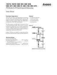
** The power losses are spitted in switching losses (CoolMOS) and conduction losses. It´s depending<br />
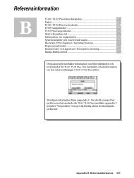
on VDCin witch part on losses having more impact of the power losses (Chart: Select your device).<br />
Chart: Select your Device (Tj @ 125°C, Ta @ 50°C, Vreflection @ 100V )<br />
<strong>Power</strong> Losses [W]<br />
1,60<br />
1,40<br />
1,20<br />
1,00<br />
0,80<br />
0,60<br />
0,40<br />
0,20<br />
<strong>Power</strong> Losses of all Devices @ typical Pout<br />
Small – Range<br />
0,00<br />
90 115 140 165 190 215 240 265 290 315 340 365<br />
Input Voltage - Vdcin [V]<br />
TDA16834@35W TDA16833_G@35W TDA16831_32_G@15W TDA16822@15W<br />
Page 23 of 28 AN-SMPS-1683X – 1<br />
V1.2
TDA1683X for OFF – Line Switch Mode <strong>Power</strong> Supplies<br />
Summary of used Nomenclature<br />
Parameters<br />
Bmax<br />
Magnetic Inductance<br />
BW Bobbin Width<br />
BWe Effective Bobbin Width<br />
CIN<br />
Capacitance of Bulk Capacitor<br />
CO<br />
Output Capacitance<br />
COSS<br />
Output Capacitance of CoolMOS<br />
CExtern<br />
Output Capacitance of external Components<br />
CSnub<br />
Capacitance of Snubber – Capacitor<br />
CVCC<br />
Capacitance of VCC – Capacitor<br />
D Duty Cycle<br />
Dmax<br />
Maximum Duty Cycle<br />
f Operating Frequency of CoolSET (f = 100kHz)<br />
fAC<br />
fg<br />
fCu<br />
fOH<br />
fOm<br />
fOL<br />
fZCOUT<br />
GC<br />
Line Frequency (Germany FAC = 50Hz)<br />
Crossover Frequency<br />
Copper Space Factor (0,2 ... 0,4)<br />
Frequency Open Loop (High)<br />
Frequency Open Loop (middle)<br />
Frequency Open Loop (Low)<br />
Zero Frequency of output Capacitor<br />
Optocoupler Gain<br />
ICCLmax Maximum quiescent Current of CoolSET (Control IC)<br />
IFBmax<br />
Maximum Feedback Current<br />
IFBmin<br />
Minimum Feedback Current<br />
IFmax<br />
Maximum Current (Optocoupler)<br />
IKAmin<br />
Minimum Current (TL431)<br />
ILoadC<br />
VCC – Capacitor Load – Current<br />
ILPK<br />
Peak Current through the primary Inductance<br />
ILRMS<br />
Root Mean Square Current through the primary Inductance<br />
IPRMS<br />
Root Mean Square Current through the Bridge Rectifier<br />
IPRI<br />
Primary Current @ time t<br />
ISEC<br />
Secondary Current @ time t<br />
ISPK<br />
Peak Current through the secondary Inductance<br />
ISRMS<br />
Root Mean Square Current through the secondary Inductance<br />
LOUT<br />
Inductance output Filter<br />
LP<br />
Primary Inductance<br />
LLK<br />
Leakage Inductance<br />
M Margin (of Transformer)<br />
nCP<br />
Number of Clock Periods<br />
npCOUT<br />
Number of parallel output Capacitors<br />
NP<br />
Number of primary Turns<br />
NS<br />
Number of secondary Turns<br />
NAux<br />
Number of auxiliary Turns<br />
PCu<br />
<strong>Power</strong> losses of Copper Resistor<br />
PD<br />
Conduction losses<br />
PDIN<br />
<strong>Power</strong> losses input Diode<br />
PDDIODE<br />
<strong>Power</strong> losses rectifier Diode (secondary side)<br />
PIN MAX<br />
Maximum Input <strong>Power</strong><br />
POUT max<br />
Maximum Output <strong>Power</strong><br />
POUT min<br />
Minimum Output <strong>Power</strong><br />
PPCu<br />
<strong>Power</strong> losses of Copper Resistor (primary Inductance)<br />
PSCu<br />
<strong>Power</strong> losses of Copper Resistor (secondary Inductance)<br />
PSOFF Switching losses of CoolMOS Transistor (Off – Operation)<br />
PSON Switching losses of CoolMOS Transistor (On – Operation)<br />
Page 24 of 28 AN-SMPS-1683X – 1<br />
V1.2
TDA1683X for OFF – Line Switch Mode <strong>Power</strong> Supplies<br />
RCu<br />
Copper Resistor (Transformer)<br />
RDSON Resistance of switching CoolMOS Transistor (On – Operation)<br />
RL<br />
Load - Resistance<br />
RLH<br />
Maximum Load<br />
RLL<br />
Minimum Load (defined by Designer)<br />
RFB Internal Feedback Resistor (CoolSET )<br />
RPCu<br />
Copper Resistor of primary Inductance<br />
RSCu<br />
Copper Resistor of secondary Inductance<br />
RSnub<br />
Snubber Resistor<br />
Start up Resistor<br />
RStart<br />
1 1<br />
T µ<br />
3<br />
f 100*<br />
10 sec<br />
T Time of one Period = =<br />
= 10 s<br />
TD<br />
Discharging Time of Input Capacitor C3<br />
tON On Time (CoolMOS )<br />
tOFF Off Time (CoolMOS )<br />
tr<br />
Rising Time (Voltage)<br />
tStart<br />
Start up Time<br />
VAC min<br />
Minimal AC Input Voltage<br />
VAC max<br />
Maximal AC Input Voltage<br />
VAux<br />
Auxiliary Voltage<br />
V(BR)DSS<br />
Drain Source Breakdown Voltage<br />
VCCH Turn On Threshold for CoolSET @ Vcc - Pin<br />
VDC IN<br />
DC Input Voltage<br />
VDC IN max Maximum DC Input Voltage<br />
VDC IN min Minimum DC Input Voltage<br />
VDC max PK Maximum DC Input Voltage Peak<br />
VDC min PK Minimum DC Input Voltage Peak<br />
VDC min<br />
Minimum DC Input Voltage @ maximum load<br />
VDDIODE<br />
Reverse Voltage rectifier Diode (secondary side)<br />
VFBmax Maximum Feedback Voltage (CoolSET )<br />
VFDIODE<br />
Output Diode Forward Voltage<br />
VFD<br />
Forward Diode Voltage (Optocoupler)<br />
VOUT<br />
Output Voltage (secondary Side)<br />
VOUT Ripple Output Ripple Voltage (secondary Side)<br />
VR<br />
Reflected Voltage (from secondary side to primary side)<br />
VRDiode<br />
Reverse Voltage Diode<br />
VRefint Internal Reference Voltage (CoolSET )<br />
VREF<br />
Reference Voltage TL431<br />
VRipple<br />
DC Ripple Voltage (on primary Side)<br />
VSEC<br />
Voltage on Sekondary Inductor<br />
VSnub<br />
Maximum Voltage overshoot @ snubber<br />
WIN<br />
Discharging Energie Input Capacitor<br />
Transimpedanz<br />
ZPWM<br />
Page 25 of 28 AN-SMPS-1683X – 1<br />
V1.2
References<br />
TDA1683X for OFF – Line Switch Mode <strong>Power</strong> Supplies<br />
[1] Keith Billings,<br />
Switch Mode <strong>Power</strong> Supply Handbook<br />
[2] Ralph E. Tarter,<br />
Solid-State <strong>Power</strong> <strong>Conversion</strong> Handbook<br />
[3] R. D. Middlebrook and Slobodan Cuk,<br />
Advances in Switched-Mode <strong>Power</strong> <strong>Conversion</strong><br />
[4] Herfurth Michael,<br />
Ansteuerschaltungen für getaktete Stromversorgungen mit Erstellung eines<br />
linearisierten Signalflußplans zur Dimensionierung der Regelung<br />
[5] Herfurth Michael,<br />
Topologie, Übertragungsverhalten und Dimensionierung häufig eingesetzter<br />
Regelverstärker<br />
[6] Infineon Technologies,<br />
Datasheet TDA16831 ... 34 Off – Line SMPS Controller with 600V CoolMOS<br />
Transistor on Board,<br />
Revision History<br />
Application Note AN-SMPS-1683X-1<br />
Actual Release: V1.2 Date:11.05.2000 Previous Release: V1.1<br />
Page of<br />
actual<br />
Rel.<br />
Page of<br />
prev. Rel.<br />
28 21 Formatting<br />
Subjects changed since last release<br />
Page 26 of 28 AN-SMPS-1683X – 1<br />
V1.2
TDA1683X for OFF – Line Switch Mode <strong>Power</strong> Supplies<br />
For questions on technology, delivery and prices please contact the Infineon<br />
Technologies Offices in Germany or the Infineon Technologies Companies and<br />
Representatives worldwide: see the address list on the last page or our webpage at<br />
http://www.infineon.com<br />
CoolMOS and CoolSET are trademarks of Infineon Technologies AG.<br />
Edition 2000--05--11<br />
Published by Infineon Technologies AG,<br />
St.-Martin-Strasse 53,<br />
D-81541 München<br />
© Infineon Technologies AG 2000.<br />
All Rights Reserved.<br />
Attention please!<br />
The information herein is given to describe certain components and shall not be considered as warranted characteristics.<br />
Terms of delivery and rights to technical change reserved.<br />
We hereby disclaim any and all warranties, including but not limited to warranties of non-infringement, regarding circuits, descriptions and charts<br />
stated herein.<br />
Infineon Technologies is an approved CECC manufacturer.<br />
Information<br />
For further information on technology, delivery terms and conditions and prices please contact your nearest Infineon Technologies Office in<br />
Germany or our Infineon Technologies Representatives worldwide (see address list).<br />
Warnings<br />
Due to technical requirements components may contain dangerous substances. For information on the types in question please contact your<br />
nearest Infineon Technologies Office.<br />
Infineon Technologies Components may only be used in life-support devices or systems with the express written approval of Infineon<br />
Technologies, if a failure of such components can reasonably be expected to cause the failure of that life-support device or system, or to affect the<br />
safety or effectiveness of that device or system. Life support devices or systems are intended to be implanted in the human body, or to support<br />
and/or maintain and sustain and/or protect human life. If they fail, it is reasonable to assume that the health of the user or other persons may be<br />
endangered.<br />
Page 27 of 28 AN-SMPS-1683X – 1<br />
V1.2
TDA1683X for OFF – Line Switch Mode <strong>Power</strong> Supplies<br />
Infineon Technologies AG sales offices worldwide –<br />
partly represented by Siemens AG<br />
A<br />
Siemens AG Österreich<br />
Erdberger Lände 26<br />
A-1031 Wien<br />
T (+43)1-17 07-3 56 11<br />
Fax (+43)1-17 07-5 59 73<br />
AUS<br />
Siemens Ltd.<br />
885 Mountain Highway<br />
Bayswater,Victoria 3153<br />
T (+61)3-97 21 21 11<br />
Fax (+61)3-97 21 72 75<br />
B<br />
Siemens Electronic Components<br />
Benelux<br />
Charleroisesteenweg 116/<br />
Chaussée de Charleroi 116<br />
B-1060 Brussel/Bruxelles<br />
T (+32)2-5 36 69 05<br />
Fax (+32)2-5 36 28 57<br />
Email:components@siemens.nl<br />
BR<br />
Siemens Ltda.<br />
Semiconductores<br />
Avenida Mutinga,3800-Pirituba<br />
05110-901 São Paulo-SP<br />
T (+55)11-39 08 25 64<br />
Fax (+55)11-39 08 27 28<br />
CDN<br />
Infineon Technologies Corporation<br />
320 March Road,Suite 604<br />
Canada,Ontario K2K 2E2<br />
T (+1)6 13-5 91 63 86<br />
Fax (+1)6 13-5 91 63 89<br />
CH<br />
Siemens Schweiz AG<br />
Bauelemente<br />
Freilagerstrasse 40<br />
CH-8047 Zürich<br />
T (+41)1-4 953065<br />
Fax (+41)1-4 955050<br />
D<br />
Infineon Technologies AG<br />
Völklinger Str.2<br />
D-40219 Düsseldorf<br />
T (+49)2 11-3 99 29 30<br />
Fax (+49)2 11-3 99 14 81<br />
Infineon Technologies AG<br />
Werner-von-Siemens-Platz 1<br />
D-30880 Laatzen (Hannover)<br />
T (+49)5 11-8 77 22 22<br />
Fax (+49)5 11-8 77 15 20<br />
Infineon Technologies AG<br />
Von-der-Tann-Straße 30<br />
D-90439 Nürnberg<br />
T (+49)9 11-6 54 76 99<br />
Fax (+49)9 11-6 54 76 24<br />
Infineon Technologies AG<br />
Weissacher Straße 11<br />
D-70499 Stuttgart<br />
T (+49)7 11-1 37 33 14<br />
Fax (+49)7 11-1 37 24 48<br />
D<br />
Infineon Technologies AG<br />
Halbleiter Distribution<br />
Richard-Strauss-Straße 76<br />
D-81679 München<br />
T (+49)89-92 21 40 86<br />
Fax (+49)89-92 21 20 71<br />
DK<br />
Siemens A/S<br />
Borupvang 3<br />
DK-2750 Ballerup<br />
T (+45)44 77-44 77<br />
Fax (+45)44 77-40 17<br />
E<br />
Siemens S.A.<br />
Dpto.Componentes<br />
Ronda de Europa,5<br />
E-28760 Tres Cantos-Madrid<br />
T (+34)91-5 14 71 51<br />
Fax (+34)91-5 14 70 13<br />
F<br />
Infineon Technologies France,<br />
39/47,Bd.Ornano<br />
F-93527 Saint-Denis CEDEX2<br />
T (+33)1-49 22 31 00<br />
Fax (+33)1-49 22 28 01<br />
FIN<br />
Siemens Components<br />
Scandinavia<br />
P.O .Bo x 6 0<br />
FIN-02601 Espoo (Helsinki)<br />
T (+3 58)10-5 11 51 51<br />
Fax (+3 58)10-5 11 24 95<br />
Email:<br />
scs@components.siemens.se<br />
GB<br />
Infineon Technologies<br />
Siemens House<br />
Oldbury<br />
GB-Bracknell,Berkshire<br />
RG12 8FZ<br />
T (+44)13 44-39 66 18<br />
Fax (+44)13 44-39 66 32<br />
H<br />
Simacomp Kft.<br />
Lajos u.103<br />
H-1036 Budapest<br />
T (+36)1-4 57 16 90<br />
Fax (+36)1-4 57 16 92<br />
HK<br />
Infineon Technologies<br />
Hong Kong Ltd.<br />
Suite 302,Level 3,<br />
Festival Walk,<br />
80 Tat Chee Avenue,<br />
Yam Yat Tsuen,<br />
Kowloon Tong<br />
Hong Kong<br />
T (+8 52)28 32 05 00<br />
Fax (+8 52)28 27 97 62<br />
I<br />
Siemens S..A.<br />
Semiconductor Sales<br />
Via Piero e Alberto Pirelli,10<br />
I-20126 Milano<br />
T (+39)02-66 76 -1<br />
Fax (+39)02-66 76 43 95<br />
IND<br />
Siemens Ltd.<br />
Components Division<br />
No.84 Keonics Electronic City<br />
Hosur Road<br />
Bangalore 561 229<br />
T (+91)80-8 52 11 22<br />
Fax (+91)80-8 52 11 80<br />
Siemens Ltd.<br />
CMP Div,5th Floor<br />
4A Ring Road,IP Estate<br />
New Delhi 110 002<br />
T (+91)11-3 31 99 12<br />
Fax (+91)11-3 31 96 04<br />
Siemens Ltd.<br />
CMP Div,4th Floor<br />
130,Pandurang Budhkar Marg,<br />
Worli<br />
Mumbai 400 018<br />
T (+91)22-4 96 21 99<br />
Fax (+91)22-4 96 22 01<br />
IRL<br />
Siemens Ltd.<br />
Electronic Components Division<br />
8,Raglan Road<br />
IRL-Dublin 4<br />
T (+3 53)1-2 16 23 42<br />
Fax (+3 53)1-2 16 23 49<br />
IL<br />
Nisko Ltd.<br />
2A,Habarzel St.<br />
P.O.Box 58151<br />
61580 Tel Aviv –Isreal<br />
T (+9 72)3 -7 65 73 00<br />
Fax (+9 72)3 -7 65 73 33<br />
J<br />
Siemens Components K.K.<br />
Talanawa Park Tower 12F &17F<br />
3-20-14,Higashi-Gotanda,<br />
Shinagawa-ku<br />
Tokyo<br />
T (+81)3-54 49 64 11<br />
Fax (+81)3 -54 49 64 01<br />
MAL<br />
Infineon Technologies AG<br />
Sdn Bhd<br />
Bayan Lepas Free Industrial Zone1<br />
11900 Penang<br />
T (+60)4 -6 44 99 75<br />
Fax (+60)4 -6 41 48 72<br />
N<br />
Siemens Components<br />
Scandinavia<br />
Østre Aker vei 24<br />
Postboks 10,Veitvet<br />
N-0518 Oslo<br />
T (+47)22-63 30 00<br />
Fax (+47)22-68 49 13<br />
Email:<br />
scs@components.siemens.se<br />
NL<br />
Siemens Electronic Components<br />
Benelux<br />
Postbus 16068<br />
NL-2500 BB Den Haag<br />
T (+31)70-3 33 20 65<br />
Fax (+31)70-3 33 28 15<br />
Email:components@siemens.nl<br />
NZ<br />
Siemens Auckland<br />
300 Great South Road<br />
Greenland<br />
Auckland<br />
T (+64)9-5 20 30 33<br />
Fax (+64)9-5 20 15 56<br />
P<br />
Siemens S.A.<br />
an Componentes Electronicos<br />
R.Irmaos Siemens,1<br />
Alfragide<br />
P-2720-093 Amadora<br />
T (+351)1-4 17 85 90<br />
Fax (+351)1-4 17 80 83<br />
PK<br />
Siemens Pakistan Engineering<br />
Co.Ltd.<br />
PO Box 1129,Islamabad 44000<br />
23 West Jinnah Ave<br />
Islamabad<br />
T (+92)51-21 22 00<br />
Fax (+92)51-21 16 10<br />
PL<br />
Siemens SP.z.o.o.<br />
ul.Zupnicza 11<br />
PL-03-821 Warszawa<br />
T (+48)22-8 70 91 50<br />
Fax (+48)22-8 70 91 59<br />
ROK<br />
Siemens Ltd.<br />
Asia Tower,10th Floor<br />
726 Yeoksam-dong,Kang-nam Ku<br />
CPO Box 3001<br />
Seoul 135-080<br />
T (+82)2-5 27 77 00<br />
Fax (+82)2-5 27 77 79<br />
RUS<br />
INTECH electronics<br />
ul.Smolnaya,24/1203<br />
RUS-125 445 Moskva<br />
T (+7)0 95 -4 51 97 37<br />
Fax (+7)0 95 -4 51 86 08<br />
S<br />
Siemens Components Scandinavia<br />
Österögatan 1,Box 46<br />
S-164 93 Kista<br />
T (+46)8-7 03 35 00<br />
Fax (+46)8-7 03 35 01<br />
Email:<br />
scs@components.siemens.se<br />
RC<br />
Infineon Technologies<br />
Asia Pacific Pte.Ltd.<br />
Taiwan Branch<br />
10F,No.136 Nan King East Road<br />
Section 23,Taipei<br />
T (+8 86)2-27 73 66 06<br />
Fax (+8 86)2-27 71 20 76<br />
SGP<br />
Infineon Technologies Asia<br />
Pacific,Pte.Ltd.<br />
168 Kallang Way<br />
Singapore 349 253<br />
T (+65)8 40 06 10<br />
Fax (+65)7 42 62 39<br />
USA<br />
Infineon Technologies Corporation<br />
1730 North First Street<br />
San Jose,CA 95112<br />
T (+1)4 08-5 01 60 00<br />
Fax (+1)4 08-5 01 24 24<br />
Siemens Components,Inc.<br />
Optoelectronics Division<br />
19000 Homestead Road<br />
Cupertino,CA 95014<br />
T (+1)4 08-2 57 79 10<br />
Fax (+1)4 08-7 25 34 39<br />
Siemens Components,Inc.<br />
Special Products Division<br />
186 Wood Avenue South<br />
Iselin,NJ 08830-2770<br />
T (+1)7 32-9 06 43 00<br />
Fax (+1)7 32-6 32 28 30<br />
VRC<br />
Infineon Technologies<br />
Hong Kong Ltd.<br />
Beijing Office<br />
Room 2106,Building A<br />
Vantone New World Plaza<br />
No.2 Fu Cheng Men Wai Da Jie<br />
Jie<br />
100037 Beijing<br />
T (+86)10 -68 57 90 -06,-07<br />
Fax (+86)10 -68 57 90 08<br />
Infineon Technologies<br />
Hong Kong Ltd.<br />
Chengdu Office<br />
Room14J1,Jinyang Mansion<br />
58 Tidu Street<br />
Chengdu,<br />
Sichuan Province 610 016<br />
T (+86)28-6 61 54 46 /79 51<br />
Fax (+86)28 -6 61 01 59<br />
Infineon Technologies<br />
Hong Kong Ltd.<br />
Shanghai Office<br />
Room1101,Lucky Target Square<br />
No.500 Chengdu Road North<br />
Shanghai 200003<br />
T (+86)21-63 6126 18 /19<br />
Fax (+86)21-63 61 11 67<br />
Infineon Technologies<br />
Hong Kong Ltd.<br />
Shenzhen Office<br />
Room 1502,Block A<br />
Tian An International Building<br />
Renim South Road<br />
Shenzhen 518 005<br />
T (+86)7 55 -2 28 91 04<br />
Fax (+86)7 55-2 28 02 17<br />
ZA<br />
Siemens Ltd.<br />
Components Division<br />
P.O.B.3438<br />
Halfway House 1685<br />
T (+27)11-6 52 -27 02<br />
Fax (+27)11-6 52 20 42<br />
Page 28 of 28 AN-SMPS-1683X – 1<br />
V1.2