Cracks of concrete and repair works.pdf
Cracks of concrete and repair works.pdf
Cracks of concrete and repair works.pdf

Create successful ePaper yourself
Turn your PDF publications into a flip-book with our unique Google optimized e-Paper software.
Eng. Yaseen Srewil. Module G-4 Dresden Seminar „Rehabilitation Engineering“<br />
Supervision. Pr<strong>of</strong>. Dr.Ing. Harald Schorn Institutes für Baust<strong>of</strong>fe<br />
Abstract.<br />
<strong>Cracks</strong> <strong>of</strong> <strong>concrete</strong> <strong>and</strong> <strong>repair</strong> <strong>works</strong> & case study<br />
Eng. Yaseen Srewil.<br />
Supervision. Pr<strong>of</strong>. Dr.Ing. Harald Schorn<br />
This report will discuss the common reason <strong>of</strong> steel reinforcement<br />
<strong>concrete</strong> cracks, rack <strong>repair</strong> method <strong>and</strong> the material, which inject<br />
into this cracks. In addition, will be applied the <strong>repair</strong> principle on<br />
real projects (Deira– Shindagah tunnel in Dubai).<br />
1. Common reason <strong>of</strong> steel reinforced <strong>concrete</strong> cracks.<br />
Corrosion <strong>and</strong> freeze/thaw cycles may damage poorly designed or constructed<br />
reinforced <strong>concrete</strong>. When rebar corrodes, the oxidation products (rust) take more<br />
space than the original steel <strong>and</strong> tend to flake, cracking the <strong>concrete</strong> <strong>and</strong> unbonding<br />
the rebar from the <strong>concrete</strong>.<br />
1.1 Carbonation<br />
The water in the pores <strong>of</strong> the cement is normally alkaline, this alkaline environment is<br />
one in which the steel is passive <strong>and</strong> does not corrode. According to the pourbaix diagram<br />
for iron, the metal is passive when pH is above 9.5 [6] . The carbon dioxide from the air<br />
reacts with the alkali in the cement <strong>and</strong> makes the pore water more acidic, thus lowering<br />
the pH. Carbon dioxide will start to carbonate the cement in the <strong>concrete</strong> from the<br />
moment the object is made, this process will start at the surface <strong>and</strong> slowly move deeper<br />
<strong>and</strong> deeper into the <strong>concrete</strong>. If the object is cracked, the carbon dioxide <strong>of</strong> the air will be<br />
more able to penetrate deep into the <strong>concrete</strong>. When designing a <strong>concrete</strong> structure it is<br />
normal to state the <strong>concrete</strong> cover for the rebar (the depth within the object that the rebar<br />
will be). The minimum <strong>concrete</strong> cover is normally regulated by design or building codes.<br />
If the reinforcement is too close to the surface, then an early failure due to corrosion may<br />
occur.<br />
1
Eng. Yaseen Srewil. Module G-4 Dresden Seminar „Rehabilitation Engineering“<br />
Supervision. Pr<strong>of</strong>. Dr.Ing. Harald Schorn Institutes für Baust<strong>of</strong>fe<br />
One method <strong>of</strong> testing a structure<br />
For carbonation is to drill afresh hole<br />
in the surface <strong>and</strong> then treat the<br />
surface) with phenolphthalein, this<br />
will turn pink when in contact with<br />
alkaline cement. It is then possible to<br />
see the depth <strong>of</strong> carbonation. An<br />
existing hole is no good, as the<br />
surface will already be carbonated.<br />
As we see in the figure (1.1)<br />
1.2 Chlorides<br />
Chlorides, including sodium chloride, promote the corrosion <strong>of</strong> steel rebar. For this<br />
reason, in mixing <strong>concrete</strong> only fresh water may be used, <strong>and</strong> the use <strong>of</strong> salt for deicing<br />
<strong>concrete</strong> pavements is strongly discouraged. As illustrated in figure (1.2).<br />
1.3 Alkali silica reaction<br />
This is found when the cement is too alkaline;<br />
It is due to a reaction <strong>of</strong> the silica<br />
with the alkali. The silica (SiO2)<br />
reacts with the alkali to form a<br />
silicate in the Alkali silica reaction<br />
(ASR), this causes localized swelling<br />
which causes cracking. [5] [4]<br />
1.4 Conversion <strong>of</strong> high alumina cement<br />
Figure (1.1) Carbonations affect [5]<br />
Figure (1.2) Alkali silica reaction affects [5]<br />
Resistant to weak acids <strong>and</strong> especially sulfates, this cement cures quickly <strong>and</strong> reaches<br />
very high durability <strong>and</strong> strength. It was greatly used after World War Two for making<br />
precast <strong>concrete</strong> objects. However, it can lose strength with heat or time (conversion),<br />
especially when not properly cured. With the collapse <strong>of</strong> three ro<strong>of</strong>s made <strong>of</strong> prestressed<br />
2
Eng. Yaseen Srewil. Module G-4 Dresden Seminar „Rehabilitation Engineering“<br />
Supervision. Pr<strong>of</strong>. Dr.Ing. Harald Schorn Institutes für Baust<strong>of</strong>fe<br />
<strong>concrete</strong> beams using high alumina cement, this cement was banned in the UK in 1976.<br />
Subsequent inquiries into the matter showed that the beams were improperly<br />
manufactured, but the ban remained.<br />
1.5 Sulfate attack<br />
Sulphates in soil or<br />
Groundwater can react with<br />
Portl<strong>and</strong> cement causing<br />
expansive products, e.g. ettringite<br />
or thaumasite, which can lead to<br />
early failure. Fig (1.5).<br />
1.6. Cracking caused by Physical Processes.<br />
Dead <strong>and</strong> live loads induce stresses in a <strong>concrete</strong> structure. Depending on type <strong>of</strong><br />
structure element <strong>and</strong> on type <strong>of</strong> loading compression, tension or shear stress occurs. If<br />
these stresses exceed the respective strength <strong>of</strong> <strong>concrete</strong> the structure fails caused by<br />
cracking.<br />
2. Crack <strong>repair</strong> methods<br />
2. 1 General<br />
<strong>Cracks</strong> must be <strong>repair</strong>ed for the following reasons:<br />
Figure (1.5) intringite affect [5]<br />
• To reduce or prevent ingress <strong>of</strong> adverse agents, e.g. water, other liquids, vapour, gas,<br />
chemicals <strong>and</strong> biological agents. Principle 1 According to Principles <strong>and</strong> Methods related<br />
to reinforcement corrosion). [3]<br />
• To increase or restore the structural load-bearing capacity <strong>of</strong> an element <strong>of</strong> the <strong>concrete</strong><br />
structure. Principle 4 According to Principles <strong>and</strong> Methods related to reinforcement<br />
corrosion. [3]<br />
3
Eng. Yaseen Srewil. Module G-4 Dresden Seminar „Rehabilitation Engineering“<br />
Supervision. Pr<strong>of</strong>. Dr.Ing. Harald Schorn Institutes für Baust<strong>of</strong>fe<br />
While crack injection agents are usually applied, other measures can or must be taken<br />
occasionally in order to <strong>repair</strong> a crack. In deciding upon the method to be applied, much<br />
depends on which function must be restored <strong>and</strong> whether or not the cause <strong>of</strong> cracking is<br />
still present <strong>and</strong> may be reactivated. In the case <strong>of</strong> live cracks, one must be aware that<br />
completely filling up those cracks by injection will always lead to new cracking within<br />
the crack filler, on the interface with the cracked <strong>concrete</strong> or within the old <strong>concrete</strong> [1] .<br />
In such cases, increasing or restoring the structural bearing capacity is not possible using<br />
the methods described in this section <strong>and</strong> structural strengthening with tendons or plate<br />
bonding must be considered.<br />
2.2 Crack injection agents<br />
Requirements for <strong>concrete</strong> crack injection products are specified in EN 1504, Part 5. The<br />
product used depends not only on the function to be discharged, but also on the<br />
conditions <strong>of</strong> the crack, notably the presence or absence <strong>of</strong> water. The type <strong>of</strong> crack must<br />
be distinguished; it can be dry, humid, water transporting without pressure or water<br />
transporting under pressure. Under the more complicated conditions <strong>of</strong> water pressure,<br />
water ingress at the crack is closed <strong>of</strong>f first, for instance by a polyurethane resin that<br />
forms a foam in contact with water. Subsequently, the crack is filled up with a massive<br />
resin. Table 1.2 presents a survey <strong>of</strong> the injection agents applied. [4]<br />
Table 1.2 Survey <strong>of</strong> crack injection agents in relation to crack condition <strong>and</strong> application [4]<br />
Application<br />
Load bearing<br />
capacity<br />
Prevent ingress<br />
Concrete condition. a<br />
Water transporting<br />
Dry Humid Without pressure With pressure<br />
EP b<br />
EP EP C<br />
EP bc<br />
EP bcd<br />
- -<br />
EP/PUR EP/PUR EP/PUR EP/PUR<br />
PUR PUR PUR PUR<br />
- GEL e GEL GEL<br />
CC CC CC CC<br />
- Not applicable<br />
EP Epoxy<br />
EP/PUR Mixture <strong>of</strong> Epoxy <strong>and</strong> Polyurethane.<br />
PUR Polyurethane.<br />
GEL Water gel bound by Polyurethane or acryl amide.<br />
CC Cement suspension<br />
Index a<br />
To be determined by visual observation<br />
EP bcd<br />
Index b Only applicable when crack is not ‘live’<br />
Index c Non-watersensitive epoxy<br />
Index d Only applicable after water ingress has ceased by applying a foaming<br />
polyurethane or other similar agent<br />
To be applied only if the conditions remain wet, for instance under water<br />
Index e<br />
4
Eng. Yaseen Srewil. Module G-4 Dresden Seminar „Rehabilitation Engineering“<br />
Supervision. Pr<strong>of</strong>. Dr.Ing. Harald Schorn Institutes für Baust<strong>of</strong>fe<br />
2.3 Other methods that prevent ingress through cracks<br />
In the case <strong>of</strong> cracks that have to be sealed <strong>of</strong>f to reduce or prevent ingress <strong>of</strong> adverse<br />
agents, the following methods can be used to seal <strong>of</strong>f the joints:<br />
• Applying elastic sealants. <strong>Cracks</strong> can be widened at the surface to reduce the stresses in<br />
the sealant due to movements <strong>of</strong> the <strong>concrete</strong>, as shown in Fig. (2.3.1)<br />
Figure (2.3.1) widening up the live crack at the surface before filling it up<br />
with a sealant to reduce stresses.<br />
• Sealing at the surface with flexible rubber strips, as shown in Fig. (2.3.2)<br />
Figure (2.3.2) Closing <strong>of</strong>f live crack to prevent adverse agent ingress.<br />
3. Protective surface treatments<br />
3.1 General<br />
A survey <strong>of</strong> <strong>concrete</strong> surface protection systems is given in this section. Such issues as<br />
why <strong>and</strong> how to protect the surface, the general requirements regarding surface protective<br />
agents <strong>and</strong> commercially available agents are considered.<br />
5
Eng. Yaseen Srewil. Module G-4 Dresden Seminar „Rehabilitation Engineering“<br />
Supervision. Pr<strong>of</strong>. Dr.Ing. Harald Schorn Institutes für Baust<strong>of</strong>fe<br />
3. 2 Types<br />
The following types <strong>of</strong> surface protection can be distinguished according to<br />
EN 1504, Part 2, Surface Protection Systems <strong>and</strong> as illustrated in Fig. (3.2.1)<br />
• Hydrophobic impregnation.<br />
• Impregnation that partially or completely fills up the pores.<br />
• Coating.<br />
Figure (3.2.1) Types <strong>of</strong> surface protection. [5], [1]<br />
In practice, hydrophobic impregnation <strong>and</strong> coating are the most important. When<br />
<strong>concrete</strong> is made water-repellent by hydrophobing, the walls <strong>of</strong> the <strong>concrete</strong> pores are<br />
lined with a hydrophobic agent by means <strong>of</strong> the suction <strong>of</strong> the agent into the <strong>concrete</strong>.<br />
This process is sometimes aided by previous artificial drying. Hydrophobing does not<br />
significantly influence transport <strong>of</strong> water vapour, but can considerably reduce water<br />
absorption.<br />
In cases <strong>of</strong> impregnation <strong>and</strong> filling up <strong>of</strong> pores, the <strong>concrete</strong> surface is penetrated by an<br />
agent that fills up the pores. Impregnation can be performed by making use <strong>of</strong> the<br />
absorptive capacity <strong>of</strong> <strong>concrete</strong>, which can be promoted by drying the surface <strong>and</strong>/or<br />
evacuating the air. A distinction can be made between agents that fill up the pores by<br />
reacting with constituents <strong>of</strong> <strong>concrete</strong> <strong>and</strong> agents that do not react with <strong>concrete</strong>.<br />
At locations where the pores <strong>of</strong> the <strong>concrete</strong> surface layer become totally filled up by<br />
impregnation, the process is referred to as sealing. By applying a coating, the <strong>concrete</strong><br />
protection based on the layer which covering the <strong>concrete</strong>.<br />
Coatings distinguish by thickness:<br />
• Thin coatings: layers less than 100mm thick.<br />
• Thick coatings: layers between 100 <strong>and</strong> 500mm thick.<br />
• Plasters both with an organic <strong>and</strong> an inorganic basis that have thicknesses <strong>of</strong> between<br />
500mm <strong>and</strong> 5mm.<br />
6
Eng. Yaseen Srewil. Module G-4 Dresden Seminar „Rehabilitation Engineering“<br />
Supervision. Pr<strong>of</strong>. Dr.Ing. Harald Schorn Institutes für Baust<strong>of</strong>fe<br />
A survey <strong>of</strong> the various methods <strong>of</strong> surface protection is given in Table 3.2.1 [1]<br />
Treatment<br />
Hydrophobing<br />
Impregnate/fill<br />
up pores<br />
Thin coatings<br />
Thick coatings<br />
Inorganic plasters<br />
Organic plasters/high built<br />
coatings<br />
Film membranes<br />
Effect<br />
Water-repelling/water<br />
vapour permeable; not<br />
resistant to<br />
chemical loading<br />
Decrease water absorption<br />
<strong>and</strong> increase water <strong>and</strong><br />
water<br />
vapour resistance; not<br />
resistant to chemical<br />
loading<br />
Water <strong>and</strong> water vapour<br />
tight; sensitive to<br />
mechanical<br />
loading; restricted chemical<br />
<strong>and</strong> thermal resistance<br />
Water <strong>and</strong> water vapour<br />
tight; fine<br />
more resistant than thin<br />
coatings<br />
Fairly watertight, water<br />
vapour<br />
permeable; no chemical<br />
resistance (excluding<br />
special<br />
types)<br />
Water <strong>and</strong> water vapour<br />
tight;<br />
resistant to chemical<br />
loading;<br />
less resistant to mechanical<br />
loading<br />
Water <strong>and</strong> water vapour<br />
tight<br />
resistant to chemical<br />
loading,<br />
less resistant to mechanical<br />
loading<br />
Substrate conditions<br />
Fine pores<br />
Fine pores<br />
Smooth surface, free from<br />
large pores <strong>and</strong> cracks a<br />
Smooth surface, non-living<br />
cracks allowed<br />
Free <strong>of</strong> large macro pores<br />
(air bubbles, honeycombs)<br />
Non-living<br />
Fine cracks allowed a<br />
Free <strong>of</strong> macro pores,<br />
Non-living,<br />
Fine cracks allowed<br />
Smooth surface<br />
<strong>Cracks</strong> to 3mm width<br />
allowed<br />
7
Eng. Yaseen Srewil. Module G-4 Dresden Seminar „Rehabilitation Engineering“<br />
Supervision. Pr<strong>of</strong>. Dr.Ing. Harald Schorn Institutes für Baust<strong>of</strong>fe<br />
Rubber lining<br />
Lining with<br />
thermoplastic<br />
sheeting or<br />
pipes<br />
Tiling<br />
Water <strong>and</strong> water vapour<br />
tight,<br />
resistant to chemical<br />
loading,<br />
temperature <strong>and</strong> mechanical<br />
loading<br />
Water <strong>and</strong> water vapour<br />
tight,<br />
resistant to chemical<br />
loading,<br />
temperature <strong>and</strong> mechanical<br />
loading<br />
Resistant depending on kind<br />
<strong>of</strong> tiles, adhesive <strong>and</strong> joint<br />
filler<br />
Index ( a ) Crack bridging ability can be increased by fibre reinforcement.<br />
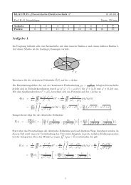
4. Study cases <strong>of</strong> <strong>repair</strong><br />
“Repair <strong>of</strong> the Deira–Shindagha tunnel in Dubai” [1]<br />
4.1 Case description<br />
Smooth<br />
Smooth<br />
Smooth<br />
A sea arm cuts <strong>of</strong>f Dubai from the Arabian Gulf <strong>and</strong>, in 1975, a 561 m long tunnel<br />
crossing the Dubai Creek was completed. A cross-section <strong>of</strong> the tunnel construction is<br />
shown in Fig. 4.1.1.The <strong>concrete</strong> was cast in place <strong>and</strong> consisted <strong>of</strong> a sulphate-resistant<br />
Portl<strong>and</strong> cement, porous limestone, coarse aggregate, beach s<strong>and</strong> with occasional<br />
chloride fractions, <strong>and</strong> tap water. The free water/cement ratio varied <strong>and</strong> could be as high<br />
as 0.6. The <strong>concrete</strong> structure was built in sections with a rubber water stop in the dilation<br />
joints <strong>and</strong> construction joints. The space in the dilations joints was filled up with<br />
bituminized cork <strong>and</strong> finished with a Neferma strip. The exterior <strong>of</strong> the tunnel was<br />
covered with Bitu-Thene sheets that were to act as a water <strong>and</strong> salt ingress barrier. A<br />
latex-cement (PC) coating with an aesthetic function was applied on the <strong>concrete</strong> innerwall.<br />
During construction, the c<strong>of</strong>ferdam on top <strong>of</strong> the already constructed tunnel section<br />
slipped away under water pressure <strong>and</strong> damaged the water impermeable Bitu-Thene<br />
layers. Although <strong>repair</strong>s were carried out, this may have caused permanent damage.<br />
8
Eng. Yaseen Srewil. Module G-4 Dresden Seminar „Rehabilitation Engineering“<br />
Supervision. Pr<strong>of</strong>. Dr.Ing. Harald Schorn Institutes für Baust<strong>of</strong>fe<br />
Longitudinal section<br />
Cross section A-A<br />
Figure (4.1.1) Schematic view <strong>of</strong> the Deira–Shindagha tunnel in Dubai.<br />
4.2 Causes <strong>of</strong> Damage<br />
Soon after completion, water leakage <strong>of</strong> Creek water through the joints was observed <strong>and</strong><br />
reinforcement corrosion was reported within a few years. Obviously, this was due to the<br />
local presence <strong>of</strong> chloride-contaminated beach s<strong>and</strong> <strong>and</strong> to the highly permeable<br />
character <strong>of</strong> the <strong>concrete</strong> applied with respect to chloride ingress.<br />
In 1983, Municipality <strong>of</strong> Dubai asked Nedeco (a Dutch joint venture <strong>of</strong> consulting<br />
engineers) to assess the damage <strong>and</strong> to advice on the possibilities <strong>of</strong> <strong>repair</strong>. Later on,<br />
Nedeco was also appointed resident engineer for the <strong>repair</strong> <strong>works</strong>. The author was the<br />
senior expert <strong>of</strong> the Nedeco team for material <strong>and</strong> corrosion aspects. On inspection,<br />
serious cracking <strong>and</strong> spalling <strong>of</strong> <strong>concrete</strong> observed. Concrete adjacent to joints was <strong>of</strong>ten<br />
pushed away from the reinforcement for several centimetres <strong>and</strong> 80mm diameter rebar<br />
had completely corroded in some locations. Although the leakage rate was not<br />
substantially higher than leakage rates in similar tunnels in the Netherl<strong>and</strong>s, the effect in<br />
this particular case proved to be highly detrimental. Obviously, this was due to the<br />
presence <strong>of</strong> the salty Creek water, the low resistance to chloride ingress <strong>of</strong> the <strong>concrete</strong>,<br />
<strong>and</strong> the high ambient temperatures. Previous <strong>repair</strong> work with epoxy <strong>repair</strong> mortars had<br />
failed. Rebars beneath the <strong>repair</strong>ed sections had continued to corrode <strong>and</strong> corrosion had<br />
probably been aggravated where it was next to the <strong>repair</strong> work. A structural design check<br />
showed that there was no immediate structural safety problem due to substantial over<br />
design. Most <strong>of</strong> the <strong>concrete</strong> appeared to be in compression.<br />
9
Eng. Yaseen Srewil. Module G-4 Dresden Seminar „Rehabilitation Engineering“<br />
Supervision. Pr<strong>of</strong>. Dr.Ing. Harald Schorn Institutes für Baust<strong>of</strong>fe<br />
4.3 Repair principle<br />
It was recommended to <strong>repair</strong> the tunnel by applying various <strong>repair</strong> principles. It was<br />
considered that the recommended combination <strong>of</strong> principles [3].<br />
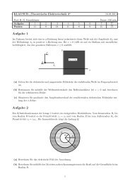
1. Stop leakage (Principle 1).<br />
Concrete around the rubber waterstop in the joints was injected with an epoxy injection<br />
agent, as schematically shown in Fig (4.3.1). This appeared to stop effectively most <strong>of</strong> the<br />
leakage.<br />
Figure(4.3.1) Rubber waterstop injected in porous <strong>concrete</strong> using a low<br />
Viscosity epoxy injection agent.<br />
2. Removal <strong>of</strong> the affected <strong>concrete</strong> <strong>and</strong> areas severely contaminated with chloride<br />
(Principle 7, Method 7.2).This occurred up to a 50 mm distance behind the reinforcement<br />
but on locations that were in a critical structural area, this had to be restricted to the<br />
reinforcement level.<br />
Figure (4.3.2)<br />
Cleaning <strong>and</strong> coating <strong>of</strong> <strong>concrete</strong><br />
in ramp walls during <strong>repair</strong> <strong>of</strong><br />
the Deira-Al Shindagha tunnel in<br />
Dubai.<br />
10
Eng. Yaseen Srewil. Module G-4 Dresden Seminar „Rehabilitation Engineering“<br />
Supervision. Pr<strong>of</strong>. Dr.Ing. Harald Schorn Institutes für Baust<strong>of</strong>fe<br />
3. Cleaning or replacing reinforcing steel bars (Principle 4, Method 4.1). [3]<br />
4. Coating the cleaned reinforcement <strong>and</strong> replacing the rebars with an epoxy barrier<br />
coating (Principle 11, Method 11.2) [3] . Fig (4.3.2) shows the cleaning <strong>and</strong> coating<br />
operation <strong>of</strong> <strong>concrete</strong> walls in the ramps.<br />
5. Replacing the removed <strong>concrete</strong> (Principle 7, Method 7.2) [3]. Initially, a polymermodified<br />
shotcrete with blast furnace slag cement CEM III/B as the cementations binder<br />
was applied (called SPCC). Later on, the polymer was replaced by silica fume for<br />
operational reasons.<br />
6. The reinforcement cover was extended by 20 mm (Principle 7, Method 7.1) [3] with the<br />
same shotcrete.<br />
7. An airtight coating was applied limiting oxygen flow to the reinforcement (Principle 9,<br />
Method 9.1) [3]. An oxygen-diffusion resistance <strong>of</strong> the coating system <strong>of</strong> 4000 m was<br />
required. In general, cutting <strong>of</strong>f oxygen ingress in <strong>concrete</strong> is difficult to achieve in <strong>repair</strong><br />
<strong>works</strong>. In the actual case <strong>of</strong> the submerged tunnel, however, it considered feasible if<br />
taken in conjunction with other measures.<br />
The coating system consisted <strong>of</strong> two epoxy coatings <strong>and</strong> a polyurethane topcoat. The<br />
topcoat showed better resistance to UV radiation, which was a specific requirement for<br />
the tunnel, ramps, <strong>and</strong> had a crack-bridging ability. Prior to applying the coating, the<br />
surface smoothed with epoxy-based equalization slurry.<br />
Repair using cathodic protection had also been considered. There were, however, two<br />
reasons for rejecting this method. In the first place, experience with cathodic protection<br />
systems in <strong>concrete</strong> structures was limited in the 1980s. In addition, electro-continuity <strong>of</strong><br />
the reinforcement was difficult to achieve. Rebars were placed in an irregular fashion <strong>and</strong><br />
sometimes even absent.<br />
4.4 Execution <strong>of</strong> the <strong>works</strong><br />
The <strong>repair</strong>s started with a trial <strong>repair</strong>, which led to modifications in the specifications. An<br />
extensive survey <strong>of</strong> the <strong>concrete</strong> was made, including crack mapping <strong>and</strong> chloride<br />
pr<strong>of</strong>iles. Repairs started in 1986 <strong>and</strong> were completed in 1988. During the whole<br />
operation, <strong>repair</strong>s were guided by calculations on the structural safety <strong>of</strong> the sections<br />
where <strong>concrete</strong> was removed <strong>and</strong> where rebars were replaced. Quality control was very<br />
strict <strong>and</strong> regarded as essential to <strong>repair</strong> work success.<br />
Part <strong>of</strong> the contract consisted in drafting a maintenance manual for the tunnel <strong>and</strong> it was<br />
regarded essential to maintain the tunnel according to strict rules. Obviously, not all<br />
affected areas could be <strong>repair</strong>ed due to structural reasons <strong>and</strong> renewed cracking in these<br />
areas could not be excluded. A thorough inspection regime would therefore take<br />
immediate action if defects were observed so as to avoid progressive deterioration. In<br />
2002 when this book was drafted, the tunnel appeared to be in excellent condition. No<br />
major <strong>repair</strong>s have been necessary since the completion <strong>of</strong> the tunnel wall <strong>repair</strong>s in<br />
1988.<br />
11
Eng. Yaseen Srewil. Module G-4 Dresden Seminar „Rehabilitation Engineering“<br />
Supervision. Pr<strong>of</strong>. Dr.Ing. Harald Schorn Institutes für Baust<strong>of</strong>fe<br />
Reference<br />
[1] Bijen J, Durability <strong>of</strong> engineering structures. Hong Kong <strong>and</strong><br />
Engl<strong>and</strong> 2003.<br />
[2] home page<br />
www.cementindustry.co.uk/main.asp?page=272 website <strong>of</strong><br />
the cement industry.<br />
[3] Principles <strong>and</strong> Methods related to reinforcement corrosion<br />
(EN 1504 Part 9).<br />
[4] Measures to Prevent Damage Due to Alkali–Silica Reaction,<br />
CUR Recommendation 89 (in Dutch) Gouda, 2002<br />
[5] Schorn H, lecture note “Building material” Master course <strong>of</strong><br />
Rehabilitation Engineering. TU Dresden 2006.<br />
[6] Silverman DC: Presence <strong>of</strong> Solid Fe(OH)2 in EMF-pH Diagram<br />
for Iron. Corrosion 1982;38:453-455.<br />
12