PG-C45X - diagramas.diagram...
PG-C45X - diagramas.diagram...
PG-C45X - diagramas.diagram...

You also want an ePaper? Increase the reach of your titles
YUMPU automatically turns print PDFs into web optimized ePapers that Google loves.
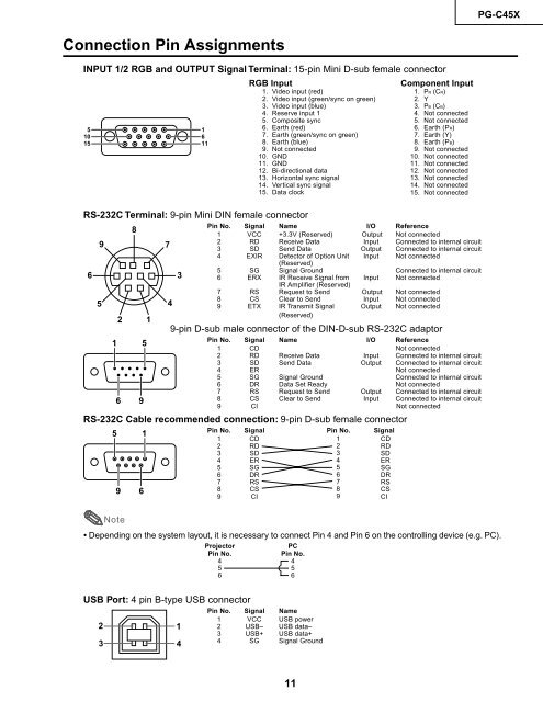
Connection Pin Assignments<br />
INPUT 1/2 RGB and OUTPUT Signal Terminal: 15-pin Mini D-sub female connector<br />
5<br />
10<br />
15<br />
RS-232C Terminal: 9-pin Mini DIN female connector<br />
Pin No. Signal Name I/O Reference<br />
1 VCC +3.3V (Reserved) Output Not connected<br />
2 RD Receive Data Input Connected to internal circuit<br />
3 SD Send Data Output Connected to internal circuit<br />
4 EXIR Detector of Option Unit<br />
(Reserved)<br />
Input Not connected<br />
5 SG Signal Ground Connected to internal circuit<br />
6 ERX IR Receive Signal from<br />
IR Amplifier (Reserved)<br />
Input Not connected<br />
7 RS Request to Send Output Not connected<br />
8 CS Clear to Send Input Not connected<br />
9 ETX IR Transmit Signal<br />
(Reserved)<br />
Output Not connected<br />
9-pin D-sub male connector of the DIN-D-sub RS-232C adaptor<br />
Pin No. Signal Name I/O Reference<br />
1 CD Not connected<br />
2 RD Receive Data Input Connected to internal circuit<br />
3 SD Send Data Output Connected to internal circuit<br />
4 ER Not connected<br />
5 SG Signal Ground Connected to internal circuit<br />
6 DR Data Set Ready Not connected<br />
7 RS Request to Send Output Connected to internal circuit<br />
8 CS Clear to Send Input Connected to internal circuit<br />
9 CI Not connected<br />
RS-232C Cable recommended connection: 9-pin D-sub female connector<br />
•<br />
6<br />
9<br />
5<br />
Note<br />
Pin No. Signal Pin No. Signal<br />
1 CD 1<br />
CD<br />
2 RD 2<br />
RD<br />
3 SD 3<br />
SD<br />
4 ER 4<br />
ER<br />
5 SG 5<br />
SG<br />
6 DR 6<br />
DR<br />
7 RS 7<br />
RS<br />
8 CS 8<br />
CS<br />
9 CI 9<br />
CI<br />
11<br />
<strong>PG</strong>-<strong>C45X</strong><br />
Depending on the system layout, it is necessary to connect Pin 4 and Pin 6 on the controlling device (e.g. PC).<br />
Projector<br />
Pin No.<br />
4<br />
5<br />
6<br />
USB Port: 4 pin B-type USB connector<br />
2<br />
3<br />
8<br />
2 1<br />
1 5<br />
6 9<br />
5 1<br />
9 6<br />
7<br />
4<br />
3<br />
1<br />
4<br />
1<br />
6<br />
11<br />
RGB Input Component Input<br />
1. Video input (red)<br />
2. Video input (green/sync on green)<br />
3. Video input (blue)<br />
4. Reserve input 1<br />
5. Composite sync<br />
6. Earth (red)<br />
7. Earth (green/sync on green)<br />
8. Earth (blue)<br />
9. Not connected<br />
10. GND<br />
11. GND<br />
12. Bi-directional data<br />
13. Horizontal sync signal<br />
14. Vertical sync signal<br />
15. Data clock<br />
PC<br />
Pin No.<br />
4<br />
5<br />
6<br />
Pin No. Signal Name<br />
1 VCC USB power<br />
2 USB– USB data–<br />
3 USB+ USB data+<br />
4 SG Signal Ground<br />
1. PR (CR)<br />
2. Y<br />
3. PB (CB)<br />
4. Not connected<br />
5. Not connected<br />
6. Earth (PR)<br />
7. Earth (Y)<br />
8. Earth (PB)<br />
9. Not connected<br />
10. Not connected<br />
11. Not connected<br />
12. Not connected<br />
13. Not connected<br />
14. Not connected<br />
15. Not connected