TV - diagramas.diagram...
TV - diagramas.diagram...
TV - diagramas.diagram...

Create successful ePaper yourself
Turn your PDF publications into a flip-book with our unique Google optimized e-Paper software.
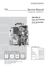
GRUNDIG Service Chassis E5<br />
Es gelten die Vorschriften und Sicherheitshinweise<br />
gemäß dem Service Manual "Sicherheit", Materialnummer<br />
720108000001, sowie zusätzlich die eventuell<br />
abweichenden, landesspezifischen Vorschriften!<br />
D<br />
Inhaltsverzeichnis<br />
Seite<br />
Allgemeiner Teil ................................. 1-2…1-12<br />
Allgemeine Hinweise .................................................................... 1-2<br />
Sicherheits-Hinweise ................................................................... 1-3<br />
Service-Hinweise ......................................................................... 1-3<br />
Technische Daten ........................................................................ 1-4<br />
Bedienhinweise ............................................................................ 1-7<br />
Service- und Sonderfunktionen .................................................. 1-11<br />
Abgleich ......................................................... 2-1<br />
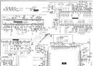
Schaltpläne<br />
und Platinenabbildungen .................. 3-1…3-18<br />
Block Diagram .............................................................................. 3-1<br />
Netzteil ......................................................................................... 3-2<br />
Horizontal-Ablenkung ................................................................... 3-3<br />
Vertikal-Ablenkung ....................................................................... 3-4<br />
Hauptteil ....................................................................................... 3-5<br />
Variantenliste ............................................................................... 3-8<br />
Chassisplatte Y25.190-04 ............................................................ 3-9<br />
Bildrohrplatte .............................................................................. 3-16<br />
Bedienplatte Y25.191; Z20.191 ................................................. 3-17<br />
Buchsenplatte Y25.195; ZL6.192 ............................................... 3-18<br />
Ersatzteillisten ...................................... 4-1…4-8<br />
Allgemeiner Teil<br />
Allgemeine Hinweise<br />
Vor dem Öffnen des Gehäuses zuerst den Netzstecker ziehen!<br />
Achtung: ESD-Vorschriften beachten<br />
Leitungsverlegung<br />
Bevor Sie die Leitungen und insbesondere die Masseleitungen lösen,<br />
muss die Leitungsverlegung zu den einzelnen Baugruppen beachtet<br />
werden.<br />
Nach erfolgter Reparatur ist es notwendig, die Leitungsführung wieder<br />
in den werkseitigen Zustand zu versetzen um evtl. spätere Ausfälle<br />
oder Störungen zu vermeiden.<br />
Durchführen von Messungen<br />
Bei Messungen mit dem Oszilloskop an Halbleitern sollten Sie nur<br />
Tastköpfe mit 10:1 - Teiler verwenden. Außerdem ist zu beachten,<br />
dass nach vorheriger Messung mit AC-Kopplung der Koppelkondensator<br />
des Oszilloskops aufgeladen sein kann. Durch die Entladung<br />
über das Messobjekt können Bauteile beschädigt werden.<br />
Messwerte und Oszillogramme<br />
Bei den in den Schaltplänen und Oszillogrammen angegebenen<br />
Messwerten handelt es sich um Näherungswerte!<br />
1 - 2<br />
GB<br />
The regulations and safety instructions shall be valid<br />
as provided by the "Safety" Service Manual, part<br />
number 720108000001, as well as the respective<br />
national deviations.<br />
Table of Contents<br />
Page<br />
General Section .................................. 1-2…1-12<br />
General Notes .............................................................................. 1-2<br />
Safety Advices ............................................................................. 1-3<br />
Service Notes ............................................................................... 1-3<br />
Technical Data ............................................................................. 1-4<br />
Operating Hints ............................................................................ 1-9<br />
Service and Special Functions ................................................... 1-11<br />
Adjustment .................................................... 2-1<br />
Circuit Diagrams<br />
and Layout of the PCBs..................... 3-1…3-18<br />
Block Diagram .............................................................................. 3-1<br />
Power Supply ............................................................................... 3-2<br />
Horizontal Deflection .................................................................... 3-3<br />
Vertical Deflection ........................................................................ 3-4<br />
Main Part ...................................................................................... 3-5<br />
Variant List ................................................................................... 3-8<br />
Chassis Board Y25.190-04 .......................................................... 3-9<br />
CRT Board ................................................................................. 3-16<br />
Keyboard Y25.191; Z20.191 ...................................................... 3-17<br />
Socket Board Y25.195; ZL6.192 ................................................ 3-18<br />
Spare Parts List .................................... 4-1…4-8<br />
General Section<br />
General Notes<br />
Before opening the cabinet disconnect the mains plug!<br />
Attention: Observe the ESD safety regulations<br />
Wiring<br />
Before disconnecting any leads and especially the earth connecting<br />
leads observe the way they are routed to the individual assemblies like<br />
the chassis, mains switch panel, keyboard control panel, picture tube<br />
panel, deflection unit, loudspeaker and so on.<br />
On completion of the repairs the leads must be laid out as originally<br />
fitted at the factory to avoid later failures or disturbances.<br />
Carrying out Measurements<br />
When making measurements on semi-conductors with an oscilloscope,<br />
ensure that the test probe is set to 10:1 dividing factor. If the<br />
previous measurement was made on AC input, please note that the<br />
coupling capacitor in the oscilloscope will be charged. Discharge via<br />
the item being checked can damage the components.<br />
Measured Values and Oscillograms<br />
The measured values given in the circuit <strong>diagram</strong>s and oscillograms<br />
are approximates!