Robinair 34700-2K 134a Recovery Unit - NY Tech Supply
Robinair 34700-2K 134a Recovery Unit - NY Tech Supply
Robinair 34700-2K 134a Recovery Unit - NY Tech Supply

You also want an ePaper? Increase the reach of your titles
YUMPU automatically turns print PDFs into web optimized ePapers that Google loves.
○ ○ ○ ○ ○ ○ ○ ○ ○ ○ ○ ○ ○ ○ ○ ○ ○ ○ ○ ○ ○ ○ ○ ○ ○ ○ ○ ○ ○ ○ ○ ○ ○ ○ ○ ○ ○ ○ ○ ○ ○ ○ ○ ○ ○ ○ ○ ○ ○ ○ ○ ○ ○ ○ ○ ○ ○ ○ ○ ○ ○ ○ ○ ○ ○ ○ ○ ○ ○ ○ ○ ○ ○ ○ ○ ○ ○ ○<br />
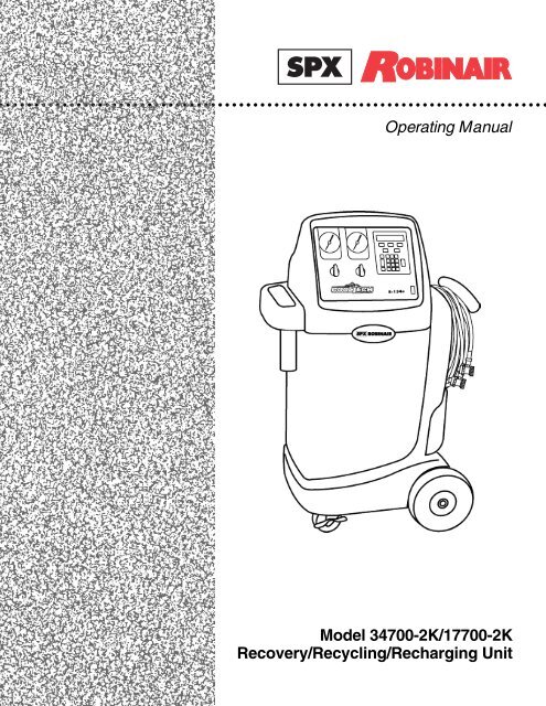
Operating Manual<br />
Model <strong>34700</strong>-<strong>2K</strong>/17700-<strong>2K</strong><br />
<strong>Recovery</strong>/Recycling/Recharging <strong>Unit</strong>
SAFETY DEFINITIONS: Follow all WARNING, CAUTION, IMPORTANT, and NOTE messages in this manual. These messages<br />
are defined as follows: WARNING means you may risk serious personal injury or death; CAUTION means you may risk personal<br />
injury, property damage, or unit damage; IMPORTANT means you may risk unit damage; and NOTEs provide clarity and helpful tips.<br />
These safety messages cover situations ROBINAIR is aware of. ROBINAIR cannot know, evaluate, and advise you as to all possible<br />
hazards. You must verify that conditions and procedures do not jeopardize your personal safety.<br />
DISCLAIMER: Information, illustrations, and specifications contained in this manual are based on the latest information available at<br />
the time of publication. The right is reserved to make changes at any time without obligation to notify any person or organization of<br />
such revisions or changes. Further, ROBINAIR shall not be liable for errors contained herein or for incidental or consequential damages<br />
(including lost profits) in connection with the furnishing, performance, or use of this material. If necessary, obtain additional health<br />
and safety information from the appropriate government agencies and the vehicle, refrigerant, and lubricant manufacturers.<br />
WARNINGS<br />
Model 17700-<strong>2K</strong> (for R-12 refrigerant)<br />
Model <strong>34700</strong>-<strong>2K</strong> (for R-<strong>134a</strong> refrigerant)<br />
Recover, Recycle, and Recharge <strong>Unit</strong><br />
ALLOW ONLY QUALIFIED PERSONNEL TO OPERATE THE UNIT. Before operating the unit, read and follow<br />
the instructions and warnings in this manual. The operator must be familiar with air conditioning and refrigeration<br />
systems, refrigerants, and the dangers of pressurized components. If the operator cannot read English, operating<br />
instructions and safety precautions must be read and discussed in the operator’s native language.<br />
Si el operador no puede leer el inglés, las instrucciones de operación y las precauciones de seguridad deberán<br />
leerse y comentarse en el idioma nativo del operador.<br />
Si l’utilisateur ne peut lire l’anglais, les instructions et les consignes de sécurité doivent lui être expliquées<br />
dans sa langue maternelle.<br />
PRESSURIZED TANK CONTAINS LIQUID REFRIGERANT. Do not overfill the internal storage vessel because<br />
overfilling may cause explosion and personal injury or death. Do not recover refrigerants into non-refillable<br />
containers; use only federally authorized refillable containers (DOT spec. 4BW or 4BA).<br />
ALL HOSES MAY CONTAIN LIQUID REFRIGERANT UNDER PRESSURE. Contact with refrigerant may<br />
cause personal injury. Wear protective equipment, including safety goggles. Disconnect hoses using extreme<br />
caution.<br />
DO NOT BREATHE REFRIGERANT AND LUBRICANT VAPOR OR MIST. Exposure may cause personal<br />
injury, especially to the eyes, nose, throat, and lungs. Use the unit in locations with mechanical ventilation that<br />
provides at least four air changes per hour. If accidental system discharge occurs, ventilate the work area before<br />
resuming service.<br />
DO NOT USE AN EXTENSION CORD. An extension cord may overheat and cause fire. If you must use an<br />
extension cord, use the shortest possible cord with a minimum size of 14 AWG.<br />
TO REDUCE THE RISK OF FIRE, do not use the unit in the vicinity of spilled or open containers of gasoline or<br />
other flammable substances.<br />
DO NOT USE COMPRESSED AIR TO PRESSURE TEST OR LEAK TEST THE UNIT OR VEHICLE AIR<br />
CONDITIONING SYSTEM. Some mixtures of air and R-<strong>134a</strong> refrigerant are combustible at elevated pressures.<br />
These mixtures are potentially dangerous and may result in fire or explosion causing personal injury or property<br />
damage.<br />
USE THE 17700-<strong>2K</strong> UNIT WITH R-12 REFRIGERANT ONLY. The unit is for recovering, recycling, and<br />
recharging only R-12 refrigerant! Do not attempt to adapt the unit for another refrigerant. Do not mix refrigerant<br />
types through a system or in the same container; mixing of refrigerants will cause severe damage to the unit<br />
and the vehicle air conditioning system.<br />
USE THE <strong>34700</strong>-<strong>2K</strong> UNIT WITH R-<strong>134a</strong> REFRIGERANT ONLY. The unit is for recovering, recycling, and<br />
recharging only R-<strong>134a</strong> refrigerant! Do not attempt to adapt the unit for another refrigerant. Do not mix refrigerant<br />
types through a system or in the same container; mixing of refrigerants will cause severe damage to the unit<br />
and the vehicle air conditioning system.<br />
HIGH VOLTAGE ELECTRICITY INSIDE THE UNIT HAS A RISK OF ELECTRICAL SHOCK. Exposure may<br />
cause personal injury. Disconnect the power before servicing the unit.<br />
OPERATING NOTE: At temperatures exceeding 120°F / 49°C, wait 10 minutes between recovery jobs.
Introduction .............................................................................................. 2<br />
Glossary of Terms ................................................................................. 2<br />
Setup Instructions.................................................................................... 2<br />
Initial Setup ............................................................................................. 4<br />
Vacuum Pump Initial Fill ......................................................................... 5<br />
Installation Routine ................................................................................. 5<br />
Operating Guidelines ............................................................................... 6<br />
Using the Selection Menu....................................................................... 6<br />
Change Filter .......................................................................................... 6<br />
Recycle ................................................................................................... 7<br />
Tank Refill............................................................................................... 7<br />
Vacuum Oil Time .................................................................................... 7<br />
Filter Capacity......................................................................................... 7<br />
Basic/Advanced Prompts ....................................................................... 8<br />
Selecting a <strong>Unit</strong> (Metric/English) ............................................................ 8<br />
Language Select..................................................................................... 8<br />
Change Defaults ..................................................................................... 9<br />
Using the Control Panel.......................................................................... 9<br />
Keypad Functions ................................................................................. 10<br />
Operating Instructions........................................................................... 11<br />
Operating Tips ...................................................................................... 11<br />
Recovering Refrigerant......................................................................... 12<br />
Evacuating the A/C System .................................................................. 14<br />
Replenishing A/C System Oil ............................................................... 16<br />
Recharging the A/C System ................................................................. 17<br />
Maintenance Instructions ...................................................................... 19<br />
Replacing the Filter-Drier...................................................................... 19<br />
Changing the Vacuum Pump Oil .......................................................... 20<br />
Checking for Leaks ............................................................................... 21<br />
Electrical Protection .............................................................................. 22<br />
General Maintenance ........................................................................... 22<br />
Replacement Parts List ......................................................................... 22<br />
Flow Diagram.......................................................................................... 24<br />
Wiring Diagram....................................................................................... 25<br />
Limited Warranty .................................................................................... 26<br />
U.S. Patents: 4,523,897; 4,688,388 Re 33,212; 4,768,347; 4,805,416; 4,809,520; 4,878,356; 4,938,031;<br />
5,005,369; 5,005,375; 5,038,578; 5,042,271; 5,209,653; 5,248,125; Australian Patent: 613,058; Canadian<br />
Patents: 1,311,621; 1,311,622; 2,012,620; 2,026,348; European Patent: 0 315 296 Bl; German Patent: 031296<br />
Mexican Patent: 16208 OTHER U.S. AND FOREIGN PATENTS PENDING.<br />
Mfd. by <strong>Robinair</strong>, SPX Corporation, Montpelier, OH 43543<br />
<strong>34700</strong>-<strong>2K</strong>/17700-<strong>2K</strong> Cool-<strong>Tech</strong> <strong>Recovery</strong>/Recycling/Recharging <strong>Unit</strong><br />
Table of Contents<br />
1
2<br />
Introduction<br />
This manual contains important safety procedures concerning the<br />
operation, use, and maintenance of this product. Failure to follow the<br />
instructions contained in this manual may result in serious injury. If you<br />
are unable to understand any of the contents of this manual, please bring<br />
it to the attention of your supervisor. Do not operate this equipment<br />
unless you have read and understood the contents of this manual.<br />
The <strong>34700</strong>-<strong>2K</strong> models are used for R-<strong>134a</strong> vehicles, whereas the 17700-<strong>2K</strong> models<br />
are used for R-12 vehicles. Both models are designed to be compatible with<br />
existing service equipment and standard service procedures.<br />
The <strong>34700</strong>-<strong>2K</strong> and the 17700-<strong>2K</strong> models are UL-listed, single-pass systems that<br />
meet the SAE specifications for recycled refrigerant.<br />
To validate your warranty, complete the warranty card attached to your unit, and<br />
return it within ten days from date of purchase.<br />
Glossary of Terms<br />
A/C System The air conditioning system being serviced.<br />
<strong>Unit</strong> The refrigerant recovery/recycling/recharging unit.<br />
Internal Storage Vessel The refillable refrigerant storage vessel designed<br />
specifically for this unit.<br />
Source Tank A disposable tank of new refrigerant used to refill<br />
the internal storage vessel.<br />
Setup Instructions<br />
Low Side<br />
Valve<br />
00<br />
00<br />
33<br />
22<br />
11<br />
00<br />
11<br />
0000<br />
00<br />
44<br />
2200 00<br />
00<br />
33<br />
RECOVER<br />
VACUUM<br />
00<br />
11<br />
55<br />
00<br />
00<br />
00<br />
22<br />
33<br />
00<br />
00<br />
3300<br />
66<br />
4400<br />
44<br />
00<br />
00<br />
22<br />
88<br />
55<br />
55 66<br />
R-134A<br />
bar<br />
kPa<br />
AA RR DD<br />
EETT<br />
CLOSED<br />
RR<br />
00 0 0<br />
4400<br />
77<br />
00<br />
88<br />
in Hg Hg<br />
VAC<br />
psi<br />
High Side<br />
Valve<br />
Low Side<br />
Gauge<br />
00<br />
00<br />
77<br />
66<br />
8800<br />
0000<br />
00<br />
11<br />
8800<br />
00<br />
00<br />
77<br />
22<br />
9900<br />
11<br />
11<br />
0000 11 00<br />
00<br />
5500<br />
RECOVER<br />
VACUUM<br />
11<br />
00<br />
00<br />
55<br />
11<br />
0000<br />
1100<br />
55<br />
0000<br />
22<br />
00<br />
00<br />
00<br />
11<br />
55<br />
55<br />
00<br />
00<br />
00<br />
11 00<br />
1155<br />
22<br />
5 00<br />
22<br />
CLOSED<br />
2200<br />
00<br />
R-134A<br />
bar<br />
kPa<br />
psi<br />
33<br />
00<br />
3344 00<br />
55<br />
00<br />
00<br />
00<br />
HIGH<br />
22<br />
00<br />
55<br />
00<br />
33<br />
0000<br />
2255<br />
00<br />
00<br />
0000<br />
3300<br />
33<br />
00<br />
55<br />
44<br />
55<br />
00<br />
0000<br />
44<br />
OIL INJECT<br />
CHARGE<br />
High Side<br />
Gauge<br />
RECOVER VACUUM VAC-CHARGE CHARGE<br />
MENU<br />
START<br />
1 2 3<br />
4 5 6<br />
7 8 9<br />
ENTER 0<br />
CLEAR<br />
STOP<br />
F1<br />
Main Power<br />
Switch<br />
0<br />
I<br />
RECOVER VACUUM<br />
MENU<br />
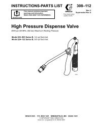
Diagram of the Control Panel<br />
START<br />
1 2 3<br />
4 5 6<br />
7 8<br />
0<br />
9<br />
CLEAR<br />
Keypad<br />
VAC-CHARGE<br />
STOP<br />
ENTER<br />
CHARGE<br />
F1<br />
INST0925<br />
© 2001 <strong>Robinair</strong>, SPX Corporation
HIGH<br />
LOW<br />
Diagram of <strong>Unit</strong>’s Components—<br />
Internal View<br />
1. Control Panel Assembly<br />
2. Vacuum Pump<br />
3. Internal Storage Vessel<br />
4. Scale Assembly<br />
5. Oil Drain Bottle<br />
6. Hose Holder<br />
7. Air Purge Control<br />
8. Vacuum Pump Oil Fill<br />
9. Sight Glass<br />
10. Oil Drain<br />
8<br />
240<br />
220<br />
7<br />
200<br />
6<br />
180<br />
160<br />
5<br />
140<br />
4<br />
120<br />
100<br />
3<br />
80<br />
2<br />
60<br />
40<br />
1<br />
20<br />
<strong>34700</strong>-<strong>2K</strong>/17700-<strong>2K</strong> Cool-<strong>Tech</strong> <strong>Recovery</strong>/Recycling/Recharging <strong>Unit</strong><br />
1<br />
2<br />
2<br />
3<br />
4<br />
5<br />
6<br />
INST0691<br />
1<br />
7<br />
4<br />
3<br />
OUNCES<br />
12<br />
11<br />
10<br />
9<br />
MLS<br />
340<br />
320<br />
300<br />
280<br />
260<br />
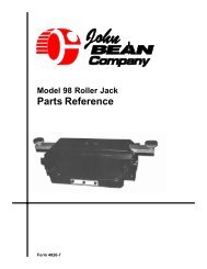
Diagram of <strong>Unit</strong>’s Components—<br />
Side View<br />
1. 1-800 Phone Number Decal<br />
2. High Side Inlet<br />
3. Low Side Inlet<br />
4. Power Cord with Tag<br />
5. Fill Hose<br />
6. Tank Strap<br />
LOW HIGH<br />
CLOSED<br />
CLOSED<br />
RECOVER RECOVER<br />
OIL INJECT<br />
VACUUM VACUUM CHARGE<br />
FLOW<br />
Setup Instructions<br />
RECOVER VACUUM<br />
VAC-CHARGE CHARGE<br />
MENU<br />
START<br />
STOP<br />
1 2 3<br />
4 5 6<br />
7 8 9<br />
CLEAR<br />
ENTER 0<br />
F1<br />
CLOSE<br />
8<br />
10<br />
6<br />
5<br />
9<br />
INST0946<br />
3
Setup Instructions<br />
4<br />
KEYPAD FUNCTIONS<br />
In addition to the number keys, the keypad contains special keys that accomplish<br />
specific operating functions.<br />
START<br />
STOP<br />
RECOVER<br />
VACUUM<br />
VAC-CHARGE<br />
CHARGE<br />
MENU<br />
F1<br />
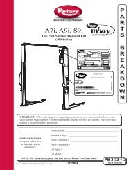
Diagram of Keypad<br />
START— Begins, or resumes, a function.<br />
STOP— Terminates, or pauses, a function.<br />
RECOVER— Activates the recovery sequence.<br />
VACUUM— Activates vacuum and automatic recycling sequence.<br />
VAC-CHARGE— Activates vacuum and automatic recycling sequence,<br />
followed by a charge.<br />
CHARGE— Charges A/C system with a programmed amount of<br />
refrigerant.<br />
MENU— Enters the selection menu.<br />
UP/DOWN ARROWS— Scroll through menu items.<br />
F1 (Inject Oil)— Injects oil into A/C system (active at end of vacuum).<br />
RECOVER VACUUM<br />
MENU<br />
START<br />
1<br />
4<br />
7<br />
CLEAR<br />
2<br />
5<br />
8<br />
0<br />
VAC-CHARGE<br />
STOP<br />
3<br />
6<br />
9<br />
ENTER<br />
CHARGE<br />
F1<br />
© 2001 <strong>Robinair</strong>, SPX Corporation
INITIAL SETUP<br />
CAUTION! R-<strong>134a</strong> systems have special fittings (per SAE<br />
specifications) to avoid cross-contamination with R-12 systems. Do not<br />
attempt to adapt your unit for another refrigerant — system failure will<br />
result! Read and follow all warnings at the beginning of this manual<br />
before operating the unit.<br />
CAUTION! Avoid the use of an extension cord, because the<br />
extension cord may overheat. However, if you must use an extension<br />
cord, use a No. 14 AWG minimum, and keep the cord as short as<br />
possible.<br />
1. The first time the unit is powered up, it will start in the initial setup mode.<br />
If the initial setup must be performed again, it may be selected using the<br />
menu function.<br />
2. The first step is to select a language. Use the UP and DOWN arrow keys to<br />
select the desired language. Press START to save the currently displayed<br />
language.<br />
3. Next select the operating units. Toggle between UNITS ENGLISH and<br />
UNITS METRIC using the arrow keys. Press START to save the currently<br />
displayed choice.<br />
4. Toggle between BASIC/ADVANCED using the ARROW keys. Use the<br />
BASIC PROMPT option to receive step-by-step, on-screen prompting<br />
through any procedure. Use ADVANCED PROMPT once you know the<br />
procedure and no longer need the step-by-step routine. Press START to<br />
save the currently displayed choice.<br />
NOTE: This manual is written using the BASIC prompt option<br />
Vacuum Pump Components<br />
1. Oil Filler Tube<br />
2. Pump Exhaust<br />
3. Oil Fill Port<br />
OPEN<br />
4. Sight Glass<br />
5. Oil Drain Fitting<br />
6. Inlet<br />
CLOSE<br />
6<br />
2<br />
1<br />
5<br />
INST0692<br />
3<br />
<strong>34700</strong>-<strong>2K</strong>/17700-<strong>2K</strong> Cool-<strong>Tech</strong> <strong>Recovery</strong>/Recycling/Recharging <strong>Unit</strong><br />
4<br />
2<br />
Diagram of Hose Connections<br />
1. Fill Hose<br />
2. Quick-Couplers (<strong>34700</strong> Only)<br />
Setup Instructions<br />
HIGH<br />
LOW<br />
1<br />
INST0701<br />
IMPORTANT!<br />
You must press<br />
the MENU key<br />
to access all the<br />
functions.<br />
5
Setup Instructions<br />
NOTE: The vacuum pump is shipped without oil in the reservoir. Before starting<br />
the pump, oil must be added to the pump, or damage to the pump may occur.<br />
6<br />
5. Press the START key to begin the oil fill process.<br />
6. Attach the flexible tube and cap to the oil bottle, and pour eight ounces of<br />
vacuum pump oil into the fill port.<br />
7. Press the START key. While the vacuum pump is running, slowly add oil<br />
until the level rises to the center of the reservoir's sight glass.<br />
8. Press the STOP key, and replace the black plastic plug on the fill port.<br />
9. Connect the service hoses, open both panel valves, and press START.<br />
10. Connect the fill hose to a full source tank.<br />
11. Open the tank valve. Invert the tank and install it on the back of the unit,<br />
making sure to secure the tank strap.<br />
NOTE: If using a refillable tank, install the tank upside down, and connect the fill<br />
hose to the vapor valve.<br />
12. Press START, and the unit will automatically run a<br />
five-minute vacuum to clear all internal air.<br />
13. After the vacuum is complete, press START to begin<br />
filling the internal storage vessel.<br />
14. The unit stops when a sufficient amount of refrigerant<br />
has been transferred to the internal tank, or when the<br />
source tank is empty. Press the STOP key to pause the<br />
process. Press STOP again to exit, or START to<br />
resume. This process takes 15-20 minutes.<br />
NOTE: Add at least 8 lb. (3.6 kg) of refrigerant before<br />
stopping the process to ensure enough refrigerant is available<br />
for charging.<br />
15. When the fill process is complete, you may press STOP<br />
to exit.<br />
16. The unit is now ready to operate.<br />
NOTE: There is no need to calibrate the scale, because it is<br />
calibrated at the factory.<br />
OUNCES<br />
12<br />
4<br />
3<br />
2<br />
1<br />
MLS<br />
340<br />
320<br />
11<br />
300<br />
10<br />
280<br />
9<br />
260<br />
8<br />
240<br />
220<br />
7<br />
200<br />
6<br />
180<br />
160<br />
5<br />
140<br />
120<br />
100<br />
80<br />
60<br />
40<br />
20<br />
FLOW<br />
RECOVER VACUUM<br />
VAC-CHARGE CHARGE<br />
START<br />
STOP<br />
LOW HIGH<br />
CLOSED<br />
CLOSED<br />
1 2 3<br />
RECOVER<br />
VACUUM<br />
RECOVER<br />
VACUUM<br />
OIL INJECT<br />
CHARGE<br />
4 5 6<br />
MENU<br />
F1<br />
7 8 9<br />
CLEAR<br />
ENTER 0<br />
IMPORTANT!<br />
For maximum<br />
performance,<br />
change the<br />
vacuum pump<br />
oil frequently.<br />
IMPORTANT!<br />
The pump must<br />
be running<br />
when adding<br />
oil.<br />
CLOSE<br />
INST0947<br />
© 2001 <strong>Robinair</strong>, SPX Corporation<br />
1<br />
2<br />
3<br />
1. Oil Fill<br />
2. Sight Glass<br />
3. Oil Drain
USING THE SELECTION MENU<br />
<strong>34700</strong>-<strong>2K</strong>/17700-<strong>2K</strong> Cool-<strong>Tech</strong> <strong>Recovery</strong>/Recycling/Recharging <strong>Unit</strong><br />
Operating Guidelines<br />
1. Press the MENU button. The top line of the display reads SETUP MENU.<br />
2. Use the UP and DOWN arrow keys to scroll through the menu choices<br />
displayed on the second line. The menu choices are:<br />
1. SELECT LANGUAGE 7. VACUUM OIL TIME<br />
2. SELECT UNITS (ENGLISH/METRIC) 8. CHANGE VACUUM PUMP OIL<br />
3. TANK REFILL 9. SELECT PROMPTS<br />
4. RECYCLE ONLY 10. CHANGE DEFAULTS (password protected)<br />
5. FILTER CAPACITY<br />
6. CHANGE FILTER<br />
11. VERSION X.XX<br />
3. Press START to make a choice from the menu. Press STOP to pause any<br />
process, and STOP a second time to exit any process.<br />
CHANGE FILTER<br />
The filter-drier removes acid, particulates, and water from the refrigerant. Change<br />
the filter-drier after 150 pounds (68 kg) of refrigerant has been filtered. See the<br />
REPLACING THE FILTER DRIER section on the following page, as well as the<br />
Maintenance Section, for instructions.<br />
RECYCLE<br />
Manual recycling may be necessary if excessive air and/or moisture is recovered<br />
from the A/C system.<br />
1. Press the MENU key. Use the arrow keys to select RECYCLE ONLY, and<br />
press START to begin.<br />
2. Press the START button to start recycling. To pause recycling, press the<br />
STOP key. To terminate recycling, press the STOP key again, or press<br />
START to resume.<br />
TANK REFILL<br />
1. Press the MENU key. Use the arrow keys to select TANK REFILL, and press<br />
START to begin.<br />
2. Connect the fill hose to the source tank.<br />
3. Open the tank valve. Invert the tank, install it on the back of the unit, and<br />
secure the tank strap.<br />
7
Operating Guidelines<br />
NOTE: If using a refillable tank, install the tank upside down, and connect the fill<br />
hose to the vapor valve.<br />
8<br />
4. Press the START key, and the tank automatically refills. The unit stops when<br />
a sufficient amount of refrigerant has been transferred to the internal tank, or<br />
if the source tank is empty. Press the STOP key to pause the process. Press<br />
STOP again to exit, or START to resume.<br />
5. When the fill process is complete, press STOP to exit.<br />
VACUUM OIL TIME<br />
This function displays how long the vacuum pump has run since the last oil<br />
change.<br />
1. Press the MENU key. Use the arrow keys to select VACUUM OIL TIME, and<br />
press START to begin.<br />
2. The display reads: OIL TIME = XX:XX This shows how long the pump has<br />
run since the last oil change. The time resets to zero after a VACUUM PUMP<br />
OIL CHANGE. See page 20 of this manual for details.<br />
3. Press STOP to exit.<br />
FILTER CAPACITY<br />
This function is used to show the operator how many pounds or kilograms of<br />
refrigerant have been recovered since the last filter change.<br />
1. Press the MENU key. Use the arrow keys to select FILTER CAPACITY, and<br />
press START to begin.<br />
2. The display reads: FILTERED= XXXlbs(kg). This shows how much<br />
refrigerant has passed through the filter. The amount filtered resets to zero<br />
after a FILTER CHANGE. See page 19 of this manual for details.<br />
3. Press STOP to exit.<br />
SELECT PROMPT (BASIC/ADVANCED)<br />
Use the BASIC PROMPT option to receive step-by-step, on-screen prompting<br />
through any procedure. Use ADVANCED PROMPT once you know the procedure<br />
and no longer need the step-by-step routine.<br />
1. Press the MENU key. Use the arrow keys to choose SELECT PROMPT, and<br />
press START to begin.<br />
2. Toggle between BASIC/ADVANCED using the ARROW keys.<br />
3. Press START to save the current choice and exit.<br />
NOTE: This manual is written for the BASIC PROMPT option.<br />
© 2001 <strong>Robinair</strong>, SPX Corporation
SELECTING A UNIT (METRIC/ENGLISH)<br />
1. Press the MENU key. Use the arrow keys to choose SELECT UNITS, and<br />
press START to begin.<br />
2. Toggle between UNITS ENGLISH and UNITS METRIC using the arrow<br />
key.<br />
3. Press START to save the current choice and exit.<br />
LANGUAGE SELECT<br />
The operator can choose between English, Spanish, French, Italian, or German.<br />
1. Press the MENU key. Use the arrow keys to choose SELECT LANGUAGE,<br />
and press START to begin.<br />
2. Use the UP and DOWN arrows to scroll through the languages.<br />
3. Press START to save the current choice. Press STOP to exit without saving.<br />
CHANGE DEFAULTS<br />
For service use only.<br />
VERSION<br />
Displays the current software revision.<br />
<strong>34700</strong>-<strong>2K</strong>/17700-<strong>2K</strong> Cool-<strong>Tech</strong> <strong>Recovery</strong>/Recycling/Recharging <strong>Unit</strong><br />
Operating Guidelines<br />
9
Operating Guidelines<br />
USING THE CONTROL PANEL<br />
The control panel has various components that control specific operating functions.<br />
MAIN POWER SWITCH—Supplies electrical power to the control panel.<br />
DIGITAL DISPLAY—Used on the visual interface between the operator and<br />
the machine.<br />
LOW SIDE MANIFOLD GAUGE—Connects to an A/C system and shows the<br />
system’s low side pressure.<br />
HIGH SIDE MANIFOLD GAUGE—Connects to an A/C system and shows the<br />
system’s high side pressure.<br />
LOW SIDE VALVE—Controls the low side flow from the A/C system through<br />
the unit.<br />
HIGH SIDE VALVE—Controls the high side flow from the A/C system through<br />
the unit. It has three positions: 1) Recover/Vacuum, 2) Closed, 3) Oil Inject/Charge.<br />
6<br />
7<br />
10<br />
3 0<br />
2 0<br />
1<br />
0<br />
1<br />
0<br />
0<br />
0<br />
4<br />
2 0<br />
0<br />
0<br />
3<br />
RECOVER<br />
VACUUM<br />
0<br />
1<br />
5<br />
0<br />
0 0<br />
2<br />
3<br />
0<br />
R-134A<br />
bar<br />
kPa<br />
in Hg<br />
VAC<br />
psi<br />
3<br />
4<br />
0<br />
0<br />
6 0<br />
0 0<br />
4<br />
2<br />
5<br />
8<br />
R E<br />
4<br />
5<br />
0<br />
0<br />
7 0<br />
0 0 6<br />
6<br />
8<br />
7<br />
0<br />
0<br />
8<br />
8 0<br />
T AR D 0<br />
12<br />
0 9<br />
0<br />
0<br />
7<br />
0<br />
0<br />
1<br />
0 1<br />
1<br />
0<br />
0<br />
CLOSED CLOSED<br />
RECOVER<br />
VACUUM<br />
10 0<br />
5 0<br />
1<br />
1 0<br />
0<br />
0<br />
5<br />
5<br />
0<br />
0<br />
0<br />
0<br />
2 0<br />
1<br />
0<br />
1<br />
5<br />
5<br />
0<br />
R-134A<br />
0<br />
0<br />
1<br />
0<br />
5<br />
2<br />
5<br />
0<br />
bar<br />
kPa<br />
psi<br />
2<br />
2<br />
0<br />
4<br />
3<br />
HIGH<br />
0<br />
00<br />
5 0<br />
0<br />
0<br />
2 5<br />
0<br />
0<br />
3<br />
3<br />
0<br />
0<br />
3 0<br />
2 0<br />
5<br />
0<br />
0<br />
0<br />
4 5<br />
0<br />
OIL INJECT<br />
CHARGE<br />
3<br />
5<br />
0<br />
1 2<br />
4 0<br />
0<br />
RECOVER VACUUM VAC-CHARGE<br />
MENU<br />
START<br />
CLEAR<br />
8<br />
0<br />
STOP<br />
1 2 3<br />
4 5 6<br />
7 9<br />
Diagram of Control Panel<br />
1. Low Side Gauge<br />
5. Main Power Switch<br />
2. High Side Gauge 6. Low Side Valve<br />
3. Display<br />
7. High Side Valve<br />
4. Bezel & Keypad Assembly<br />
ENTER<br />
CHARGE<br />
F1<br />
0<br />
I<br />
5<br />
3<br />
4<br />
INST0926<br />
© 2001 <strong>Robinair</strong>, SPX Corporation
OPERATING TIPS<br />
<strong>34700</strong>-<strong>2K</strong>/17700-<strong>2K</strong> Cool-<strong>Tech</strong> <strong>Recovery</strong>/Recycling/Recharging <strong>Unit</strong><br />
Operating Instructions<br />
Follow the SAE-J1991 recommended service procedure for the containment of<br />
R-12, and the SAE-J2210 recommended service procedure for the containment of<br />
R-<strong>134a</strong>.<br />
The recovery compressor is not a vacuum pump. The compressor pulls the A/C<br />
system to a partial vacuum only. You must use the unit’s vacuum cycle to remove<br />
moisture from the A/C system. We recommend a minimum 15-minute vacuum, or<br />
follow the system manufacturer's recommendations.<br />
This unit is designed to be used with the manifold gauge set built into the<br />
control panel.<br />
The unit includes a 6 cfm (142 l/m) <strong>Robinair</strong> high vacuum pump for fast, thorough<br />
evacuation. Change the vacuum pump oil after every 10 hours of use.<br />
R-<strong>134a</strong> systems require special oils. Refer to the A/C system manufacturer’s<br />
service manuals for oil specifications.<br />
Pressing the START and STOP keys together for several seconds will exit any<br />
mode and reset the control.<br />
NOTE: The following operating instructions are written to be used with the<br />
BASIC PROMPTS mode of operation. It is recommended that the BASIC<br />
PROMPTS mode is used until the operator becomes very familiar with the<br />
operation of the unit. See the OPERATING GUIDELINES section of this manual<br />
for instructions on how to select between BASIC PROMPTS and ADVANCED<br />
PROMPTS.<br />
11
Operating Instructions<br />
12<br />
RECOVERING REFRIGERANT<br />
33<br />
22<br />
00<br />
1100<br />
00<br />
0044<br />
00<br />
2200<br />
1100<br />
00<br />
00<br />
RECOVER<br />
VACUUM<br />
00<br />
00<br />
22<br />
11<br />
WARNING<br />
Wear safety goggles when working with refrigerant. Read and follow<br />
all warnings at the beginning of this manual before operating the unit.<br />
1. Connect the power cord to the back of the unit, and plug it into the correct<br />
voltage outlet.<br />
2. Turn on the MAIN POWER and, if necessary, empty the oil drain bottle<br />
located on the right hand side of the unit.<br />
3. Press the RECOVER button.<br />
4. If 150 pounds (68 kg) or more of refrigerant has been recovered since the last<br />
filter-drier change, the display reads FILTER WEIGHT XXX lb (XX kg).<br />
Press START.<br />
NOTE: Refer to the filter change procedure on page 19 of this manual for details<br />
about replacing the filter.<br />
5. Connect the high and low side hoses to the A/C system, and open the coupler<br />
valves.<br />
6. Put the Low Side Valve in the Recover/Vacuum position. Put the High Side<br />
Valve in the Recover/Vacuum position. Press START to continue.<br />
7. If the system pressure is below 25 psi, the display reads: LOW SYSTEM<br />
PRESSURE until the pressure increases or the START button is pressed. You<br />
may press STOP to exit at this point.<br />
8. If the unit has refrigerant in the low-side plumbing, it begins the clearing<br />
process and displays CLEARING IN PROGRESS. If you wish to skip the<br />
clearing operation or stop the clearing prematurely, press the START key.<br />
INST0928<br />
Manifold Gauges<br />
5500<br />
3300<br />
33<br />
R-134A<br />
00<br />
bar<br />
kPa<br />
in Hg<br />
VAC<br />
psi<br />
33<br />
00<br />
00<br />
00<br />
4400<br />
44<br />
55<br />
2288<br />
77<br />
RR EE<br />
CLOSED<br />
44<br />
00<br />
88<br />
AA RR DD<br />
RECOVER<br />
VACUUM<br />
Valves Open<br />
6600<br />
55<br />
00<br />
00<br />
TT<br />
66<br />
00<br />
00<br />
77<br />
66<br />
8800<br />
0000<br />
88<br />
00<br />
11<br />
00<br />
7700 00<br />
00<br />
22<br />
99<br />
00<br />
00<br />
11<br />
11<br />
1100<br />
00<br />
11<br />
00<br />
00<br />
5500<br />
11<br />
1100<br />
55<br />
55<br />
00<br />
00<br />
00<br />
22<br />
00<br />
00<br />
00<br />
00<br />
11<br />
1100<br />
55<br />
55<br />
22<br />
R-134A<br />
00<br />
00<br />
0000<br />
11<br />
55<br />
225 00<br />
bar<br />
kPa<br />
33<br />
psi<br />
CLOSED<br />
2200<br />
00<br />
33<br />
00<br />
00<br />
22<br />
0000<br />
4400 00<br />
55<br />
00<br />
00<br />
HIGH<br />
00<br />
22<br />
00<br />
55<br />
00<br />
33<br />
55<br />
0000<br />
3300<br />
00<br />
55<br />
44<br />
3355<br />
OIL INJECT<br />
CHARGE<br />
00<br />
0000<br />
44<br />
RECOVER<br />
MENU<br />
VACUUM<br />
START<br />
VAC-CHARGE<br />
STOP<br />
1 2 3<br />
4 5 6<br />
7 8 9<br />
CLEAR<br />
ENTER 0<br />
Recover<br />
CHARGE<br />
F1<br />
0<br />
I<br />
Diagram of Control Panel<br />
During <strong>Recovery</strong><br />
© 2001 <strong>Robinair</strong>, SPX Corporation
INST0699<br />
<strong>34700</strong>-<strong>2K</strong>/17700-<strong>2K</strong> Cool-<strong>Tech</strong> <strong>Recovery</strong>/Recycling/Recharging <strong>Unit</strong><br />
Operating Instructions<br />
9. When the system has recovered to a vacuum level of approximately 13 in. Hg.,<br />
the compressor automatically shuts off.<br />
10. The unit then goes into automatic oil drain, and the display reads: OIL<br />
DRAINING. Oil draining can require up to 90 seconds to complete.<br />
11. After the oil drain is complete, the display alternates between:<br />
RECOVERY COMPLETE CHECK OIL BOTTLE<br />
RECOVERED XX.XX lbs. (X.XX kg) RECOVERED XX.XX lbs. (X.XX kg)<br />
NOTE: The displayed recovered weight can vary depending on ambient conditions,<br />
and should not be used as an indicator of scale accuracy.<br />
12. Check the oil drain bottle, and note the amount of oil that was removed from<br />
the A/C system. This is the amount of oil that must be charged into the A/C<br />
system after evacuation is complete.<br />
13. To ensure complete recovery of refrigerant, wait 5 minutes, and watch the<br />
manifold gauges for a rise in pressure above 0 in. Hg. A pressure rise may<br />
occur if there was freezing in the A/C system during recovery. If a rise occurs,<br />
press the START button to resume the recovery process. Repeat as needed<br />
until the system pressure holds for two minutes, then press STOP to exit.<br />
<strong>Recovery</strong> is now complete. You are now ready to make any repairs to the A/C<br />
system, if necessary, or advance to the Evacuation Process.<br />
Diagram of the Oil<br />
Injection System<br />
1. Oil Injector Bottle<br />
2. Oil Drain Bottle<br />
1<br />
OUNCES<br />
12<br />
360<br />
340<br />
11<br />
320<br />
300<br />
10<br />
280<br />
9<br />
260<br />
8<br />
240<br />
220<br />
7<br />
200<br />
6<br />
180<br />
160<br />
5<br />
140<br />
4<br />
120<br />
100<br />
3<br />
80<br />
2<br />
60<br />
40<br />
1<br />
20<br />
2<br />
13
Operating Instructions<br />
IMPORTANT!<br />
Evacuate the<br />
system for at<br />
least 15<br />
minutes to<br />
ensure<br />
adequate<br />
moisture and<br />
contaminant<br />
removal.<br />
IMPORTANT!<br />
If the vacuum<br />
pump has run<br />
for 10 or more<br />
hours without<br />
an oil change,<br />
the message<br />
VACUUM OIL<br />
TIME XX:XX<br />
appears on the<br />
display.<br />
Change the<br />
pump oil<br />
following the<br />
procedures in<br />
the<br />
MAINTENANCE<br />
INSTRUCTIONS.<br />
14<br />
EVACUATING THE A/C SYSTEM<br />
WARNING<br />
Wear safety goggles when working with refrigerant. Use only<br />
authorized refillable refrigerant tanks. Read and follow all warnings<br />
at the beginning of this manual before operating the unit. In addition<br />
to the number keys, the keypad contains special keys that<br />
accomplish specific operating functions.<br />
NOTE:<br />
• If any oil was drained from the system during recovery, DO NOT use the VAC-<br />
CHARGE feature. The oil must be replenished into the A/C system, which is not<br />
possible when the VAC-CHARGE function is used.<br />
• If the vacuum pump has been run more than 10 hours since the last oil change,<br />
the display reads: VACUUM OIL TIME XX:XX. Press the STOP key to change<br />
the vacuum pump oil, or press the START key to continue. Instructions for<br />
changing the vacuum pump oil are located in the maintenance section of this<br />
manual. NOTE: Vacuum pump oil should be changed after every 10 hours of<br />
use to maintain maximum performance and endurance levels.<br />
• If the system being evacuated contains a pressure over 25 psi at any point during<br />
the evacuation, the display reads PRESSURE EXISTS. This message indicates<br />
that the A/C system contains refrigerant; press any key to continue. Press the<br />
RECOVERY key to recover any refrigerant in the system (See RECOVERING<br />
REFRIGERANT, page 12). After recovery is complete, return to evacuating the<br />
A/C system.<br />
VAC-CHARGE<br />
1. Press the VAC-CHARGE key to select the VAC-CHARGE feature.<br />
2. Ensure the service hoses are connected and both panel valves are in the<br />
VACUUM/ RECOVER position. Press START.<br />
The Control Panel<br />
During Evacuation<br />
3<br />
2<br />
0<br />
1 0<br />
0<br />
0 4<br />
0<br />
2 0<br />
1 0<br />
0<br />
0<br />
RECOVER<br />
VACUUM<br />
0<br />
0<br />
2<br />
1<br />
5 0<br />
3 0<br />
3<br />
R-134A<br />
0<br />
bar<br />
kPa<br />
in Hg<br />
VAC<br />
psi<br />
3<br />
0<br />
0<br />
6 0<br />
0<br />
4 0<br />
4<br />
5<br />
2 8<br />
7<br />
R E<br />
CLOSED<br />
4<br />
5<br />
0<br />
0<br />
0<br />
8<br />
AR<br />
D<br />
T<br />
6<br />
0<br />
0<br />
7<br />
6<br />
8 0<br />
0 0<br />
8<br />
0<br />
1<br />
0<br />
7 0 0<br />
0<br />
2<br />
9<br />
0<br />
0<br />
1<br />
1<br />
1 0<br />
0<br />
RECOVER<br />
VACUUM<br />
1<br />
0<br />
0<br />
5 0<br />
1<br />
1 0<br />
5<br />
5<br />
0<br />
0<br />
2<br />
0<br />
0<br />
0<br />
0<br />
0<br />
1<br />
1 0<br />
5<br />
5<br />
2<br />
R-134A<br />
0<br />
0<br />
0 0<br />
1<br />
5<br />
2 5 0<br />
bar<br />
kPa<br />
psi<br />
CLOSED<br />
2 0<br />
0<br />
3<br />
5<br />
3<br />
0<br />
0<br />
0<br />
4 0<br />
HIGH<br />
Vacuum<br />
0<br />
2<br />
0<br />
5<br />
0<br />
3<br />
0<br />
0<br />
2<br />
0 0<br />
5<br />
0 0<br />
3 0<br />
0<br />
5<br />
4<br />
3 5<br />
OIL INJECT<br />
CHARGE<br />
0<br />
0 0<br />
4<br />
RECOVER<br />
MENU<br />
VACUUM<br />
START<br />
1<br />
4<br />
7<br />
CLEAR<br />
2<br />
5<br />
8<br />
0<br />
VAC-CHARGE<br />
STOP<br />
3<br />
6<br />
9<br />
ENTER<br />
Vac-Charge<br />
CHARGE<br />
F1<br />
0<br />
I<br />
INST0929<br />
© 2001 <strong>Robinair</strong>, SPX Corporation
NOTE: It is not necessary to change the High side panel valve from vacuum to<br />
charge when performing the VAC-CHARGE function.<br />
3. Press the START key to charge the default amount of refrigerant, or use the<br />
number keys to enter the desired charge weight. Then press the START key.<br />
4. If the weight entered leaves less than 3 lbs (1.36 kg) of refrigerant in the<br />
internal storage vessel, the VAC-CHARGE process does not begin, and the<br />
display reads INSUFFICIENT REFRIG. At this point, refrigerant must be<br />
added to the internal storage vessel. See page 6 of this manual for internal<br />
storage vessel refill instructions, and then return to Step 1 of EVACUATING<br />
the A/C system.<br />
5. If the internal storage vessel contains a sufficient amount of refrigerant, press<br />
the START key to accept the default evacuation time of 15:00 minutes, or<br />
enter the desired vacuum time by using the number keys. Then press the<br />
START key.<br />
6. The unit automatically charges the A/C system after the specified vacuum<br />
time has elapsed.<br />
7. Advance to Step 4 of RECHARGING the A/C SYSTEM in this manual to<br />
complete the charging process.<br />
VACUUM<br />
1. Press the VACUUM key.<br />
2. Ensure the service hoses are connected and panel valves are in the correct<br />
position. Press START.<br />
3. Press the START key to accept the default evacuation time of 15:00 minutes,<br />
or enter the desired vacuum time by using the number keys, and press the<br />
START key.<br />
4. The unit evacuates the A/C system and stops when the specified time has<br />
elapsed. Pressing the STOP key will pause the process. Press START to<br />
resume, or STOP again to exit.<br />
5. You are now ready to replenish the A/C system oil (if necessary), or to<br />
recharge the system with refrigerant.<br />
<strong>34700</strong>-<strong>2K</strong>/17700-<strong>2K</strong> Cool-<strong>Tech</strong> <strong>Recovery</strong>/Recycling/Recharging <strong>Unit</strong><br />
Operating Instructions<br />
IMPORTANT!<br />
Evacuate the<br />
A/C system for<br />
at least 15<br />
minutes to<br />
ensure<br />
adequate<br />
moisture and<br />
contaminant<br />
removal.<br />
15
Operating Instructions<br />
16<br />
REPLENISHING A/C SYSTEM OIL<br />
CAUTION! To prevent air from entering the A/C system, never let the<br />
oil level drop below the pickup tube while charging or replenishing.<br />
Before charging the A/C system, you must replenish any oil removed from the A/C<br />
system during the recovery process. Charge only the amount of oil that was<br />
removed from the A/C system during recovery. Check the oil drain bottle to<br />
determine the amount of oil that was removed during recovery. Empty the oil drain<br />
bottle before recovering the next A/C system to prevent an inaccurate oil charge.<br />
NOTE: If no oil was removed from the A/C system during recovery, DO NOT<br />
charge any oil into the A/C system.<br />
THE VACUUM CYCLE MUST RUN COMPLETELY OR THE OIL INJECT<br />
WILL NOT OPERATE.<br />
1. Select the correct oil for the A/C system being serviced. Refer to the vehicle<br />
manufacturer's service manual.<br />
2. Adjust the o-ring around the oil injector bottle to the required oil charge level.<br />
For example, if the bottle's oil level is at 4 ounces, and you need 1/2 ounce of<br />
oil to replenish the A/C system, place the o-ring at the 3 1/2 ounce level.<br />
3. Reattach the oil injector bottle to the unit.<br />
4. Close the Low Side manifold valve. Put the High Side valve in the Oil Inject/<br />
Charge position.<br />
5. Press the F1 (INJECT OIL) button once and release it when it “beeps.” Press<br />
the F1 button again and hold it until the oil level reaches the o-ring.<br />
6. Press the STOP button after the oil charge is complete to recharge the A/C<br />
system with refrigerant. You must recharge the AC system with refrigerant at<br />
this time to ensure all of the oil is delivered.<br />
3<br />
2<br />
0<br />
1 0<br />
0<br />
0 4<br />
0<br />
2 0<br />
1 0<br />
0<br />
0<br />
RECOVER<br />
VACUUM<br />
0<br />
0<br />
2<br />
1<br />
5 0<br />
3 0<br />
INST0930<br />
3<br />
R-134A<br />
0<br />
bar<br />
kPa<br />
in Hg<br />
VAC<br />
psi<br />
3<br />
0<br />
0<br />
6 0<br />
0<br />
4 0<br />
4<br />
5<br />
2 8<br />
7<br />
R E<br />
CLOSED<br />
4<br />
5<br />
0<br />
8<br />
AR<br />
D<br />
0<br />
T<br />
0<br />
6<br />
0<br />
0<br />
7<br />
6<br />
8 0<br />
0 0<br />
8<br />
0<br />
1<br />
0<br />
7 0 0<br />
0<br />
2<br />
9<br />
0<br />
0<br />
1<br />
1<br />
1 0<br />
0<br />
RECOVER<br />
VACUUM<br />
1<br />
0<br />
0<br />
5 0<br />
1<br />
1 0<br />
5<br />
5<br />
0<br />
0<br />
2<br />
0<br />
0<br />
0<br />
0<br />
0<br />
1<br />
1 0<br />
5<br />
5<br />
2<br />
R-134A<br />
0<br />
0<br />
0 0<br />
1<br />
5<br />
2 5 0<br />
bar<br />
kPa<br />
psi<br />
CLOSED<br />
2 0<br />
0<br />
3<br />
5<br />
3<br />
0<br />
0<br />
0<br />
4 0<br />
HIGH<br />
0<br />
2<br />
0<br />
5<br />
0<br />
3<br />
0<br />
0<br />
2<br />
0 0<br />
5<br />
0 0<br />
3 0<br />
0<br />
5<br />
4<br />
3 5<br />
OIL INJECT<br />
CHARGE<br />
0<br />
0 0<br />
4<br />
RECOVER<br />
Control Panel<br />
MENU<br />
VACUUM<br />
START<br />
1<br />
4<br />
7<br />
CLEAR<br />
2<br />
5<br />
8<br />
0<br />
VAC-CHARGE<br />
STOP<br />
3<br />
6<br />
9<br />
ENTER<br />
CHARGE<br />
F1<br />
0<br />
I<br />
Inject<br />
Oil<br />
Button<br />
Oil<br />
Inject<br />
Bottle<br />
OUNCES<br />
12<br />
11<br />
360<br />
340<br />
320<br />
300<br />
10<br />
280<br />
9<br />
260<br />
8<br />
240<br />
220<br />
7<br />
200<br />
6<br />
180<br />
160<br />
5<br />
140<br />
4<br />
120<br />
100<br />
3<br />
80<br />
2<br />
60<br />
40<br />
1<br />
20<br />
Oil<br />
Drain<br />
Bottle<br />
INST0699<br />
Diagram of the Oil Injection System<br />
© 2001 <strong>Robinair</strong>, SPX Corporation
RECHARGING THE A/C SYSTEM<br />
WARNING<br />
Wear safety goggles when working with refrigerant. Use only<br />
authorized refillable refrigerant tanks. Disconnect hoses with<br />
extreme caution! All hoses may contain liquid refrigerant under<br />
pressure. Read and follow all warnings at the beginning of this<br />
manual before operating the unit.<br />
1. Press the CHARGE button. (If an oil inject has been performed, the<br />
CHARGE key does not have to be pressed.)<br />
<strong>34700</strong>-<strong>2K</strong>/17700-<strong>2K</strong> Cool-<strong>Tech</strong> <strong>Recovery</strong>/Recycling/Recharging <strong>Unit</strong><br />
Operating Instructions<br />
2. Put the Low Side Valve in the Closed position. Put the High Side Valve in<br />
the Oil Inject/Charge position. Press START to continue.<br />
3. Accept either the default weight by pressing START, or type in a weight<br />
with the number keys, and press START.<br />
4. If the weight entered will leave less than 3 lbs (1.36 kg) of refrigerant in the<br />
refrigerant tank, the charge function will not start, and the display reads:<br />
INSUFFICIENT REFRIG.<br />
PRESS A<strong>NY</strong> KEY TO EXIT<br />
See the Operating Guidelines section of the manual for refill instructions.<br />
5. Upon entering a valid charge weight, the display reads:<br />
CHARGE IN PROGRESS<br />
CHARGED= X.XX lbs. (X.XX kg)<br />
6. If, during the charge cycle, the weight fails to charge 0.05 lbs (0.02 kg) in 30<br />
seconds, the unit intermittently beeps while the display alternates between:<br />
CHARGING HAS SLOWED CHARGE HAS SLOWED<br />
PRESS START TO RETRY OR STOP TO EXIT<br />
7. Pressing the START button when the charging is slowed causes the charge<br />
to resume. If charging does not complete, see the SLOW CHARGE<br />
PROCEDURE below.<br />
8. When the charge is complete the display will show<br />
CHARGE COMPLETE<br />
X.XXlb (kg) CHARGED<br />
9. For R-<strong>134a</strong> systems, close the high and low side coupler valves. Remove the<br />
service hoses from the A/C system.<br />
The A/C system is now ready for use.<br />
IMPORTANT!<br />
Evacuate the<br />
A/C system for<br />
at least 15<br />
minutes for<br />
adequate<br />
moisture and<br />
contaminant<br />
removal.<br />
17
Operating Instructions<br />
18<br />
SLOW CHARGE PROCEDURE<br />
WARNING<br />
Before starting the vehicle's engine, verify that it is in PARK or<br />
NEUTRAL, with the emergency brake ON.<br />
Never run a vehicle without adequate ventilation in the work area.<br />
CAUTION! Close the high side manifold valve before starting the<br />
vehicle A/C system.<br />
1. Close the High Side Valve. Put the Low Side Valve in the Recover/Vacuum<br />
position.<br />
2. Start the vehicle, and set the AC system to its maximum setting.<br />
3. Press START. The unit charges out of the low side inlet only, allowing the<br />
vehicle's compressor to pull the refrigerant into the A/C system.<br />
4. When the unit is finished charging, the display reads:<br />
CHARGE COMPLETE<br />
X.XX lb (kg) CHARGED<br />
5. Close the LOW SIDE manifold valve.<br />
6. Turn off the vehicle's engine.<br />
7. For R-<strong>134a</strong> systems, close the high and low side coupler valves. Remove the<br />
service hoses from the A/C system.<br />
The A/C system is now ready for use.<br />
© 2001 <strong>Robinair</strong>, SPX Corporation
REPLACING THE FILTER-DRIER<br />
Order part no. 34724 for a replacement filter-drier. The filterdrier<br />
on this unit is designed to trap acid and particulates, and<br />
is formulated to remove water from the refrigerant. You must<br />
change the filter-drier to ensure adequate moisture and<br />
contaminant removal.<br />
Typically, you can recycle up to 150 pounds (68 kilograms)<br />
of refrigerant between filter changes.<br />
CAUTION! For best results, use <strong>Robinair</strong> filterdriers<br />
(part no. 34724). All performance tests and<br />
claims are based on using this specially blended<br />
filter-drier. Use of another may affect performance<br />
results.<br />
1. Press the MENU button.<br />
2. Scroll through the menu to CHANGE FILTER and<br />
press START.<br />
3. Press START again, and the unit will begin clearing the<br />
filter.<br />
4. When clearing is complete, the display reads:<br />
TURN UNIT OFF AND REPLACE FILTER<br />
5. Turn off the main power, and unplug the machine.<br />
6. Open the unit door, and replace the old filter with<br />
the new filter.<br />
7. Close the unit door, plug in the machine, and turn<br />
on the Main Power.<br />
The filter change is now complete.<br />
<strong>34700</strong>-<strong>2K</strong>/17700-<strong>2K</strong> Cool-<strong>Tech</strong> <strong>Recovery</strong>/Recycling/Recharging <strong>Unit</strong><br />
Maintenance Instructions<br />
MAIN POWER BREAKER CONTROL BREAKER<br />
Filter-Drier<br />
Location of the Filter-Drier<br />
OUNCES MLS<br />
12<br />
340<br />
11<br />
320<br />
300<br />
10<br />
280<br />
9<br />
260<br />
8<br />
240<br />
220<br />
7<br />
200<br />
6<br />
180<br />
160<br />
5<br />
140<br />
4<br />
120<br />
100<br />
3<br />
80<br />
2<br />
60<br />
40<br />
1<br />
20<br />
INST0478<br />
Filter<br />
Drier<br />
INST0948<br />
19
Maintenance Instructions<br />
IMPORTANT!<br />
Review current<br />
local, state, and<br />
federal statutes,<br />
cases, laws, and<br />
regulations to<br />
determine the<br />
current status and<br />
appropriate<br />
disposal method<br />
for pump oil. It is<br />
the responsibility<br />
of the user to<br />
determine if a<br />
material is a<br />
hazardous waste<br />
at the time of<br />
disposal. Ensure<br />
that you are in<br />
compliance with<br />
all applicable laws<br />
and regulations.<br />
OUNCES<br />
MLS<br />
12<br />
340<br />
11<br />
320<br />
300<br />
10<br />
280<br />
9<br />
260<br />
8<br />
240<br />
220<br />
7<br />
200<br />
6<br />
180<br />
160<br />
5<br />
140<br />
4<br />
120<br />
100<br />
3<br />
80<br />
2<br />
60<br />
40<br />
1<br />
20<br />
20<br />
LOW HIGH<br />
CLOSED<br />
CLOSED<br />
RECOVER RECOVER<br />
OIL INJECT<br />
VACUUM VACUUM CHARGE<br />
FLOW<br />
RECOVER VACUUM<br />
VAC-CHARGE CHARGE<br />
START<br />
STOP<br />
1 2 3<br />
4 5 6<br />
MENU<br />
F1<br />
7 8 9<br />
CLEAR<br />
ENTER 0<br />
CLOSE<br />
CHANGING THE VACUUM PUMP OIL<br />
For maximum vacuum pump performance, change the vacuum pump oil after<br />
every 10 hours of operation.<br />
1. Turn on the MAIN POWER switch.<br />
2. Press the MENU button.<br />
NOTE: Do not connect the service hoses to a vehicle.<br />
3. Use the arrow keys to select CHANGE VACUUM PUMP OIL, and press<br />
START.<br />
4. Press START again to begin.<br />
5. The vacuum pump will run for two minutes. Allow the vacuum pump to run<br />
until it automatically stops.<br />
6. Remove the black plastic plug on the oil fill port of the vacuum pump.<br />
7. Remove the oil drain cap from the vacuum pump, and drain the oil into a<br />
suitable container for correct disposal.<br />
8. Replace the oil drain cap.<br />
9. Attach the flexible tube and cap to the oil bottle, and pour eight ounces of<br />
vacuum pump oil into the fill port.<br />
1<br />
2<br />
INST0947<br />
3<br />
1. Oil Fill<br />
2. Sight Glass<br />
3. Oil Drain<br />
10. Press the START key. While the vacuum pump is<br />
running, slowly add oil until the level rises to the center of<br />
the reservoir's sight glass.<br />
11. Press the STOP key and replace the black plastic plug on<br />
the fill port.<br />
12. The unit is now ready to operate.<br />
© 2001 <strong>Robinair</strong>, SPX Corporation
CHECKING FOR LEAKS<br />
<strong>34700</strong>-<strong>2K</strong>/17700-<strong>2K</strong> Cool-<strong>Tech</strong> <strong>Recovery</strong>/Recycling/Recharging <strong>Unit</strong><br />
Maintenance Instructions<br />
Every three months, or as specified by local or state laws, you should check the<br />
unit for leaks.<br />
1. Turn off the MAIN POWER switch, and disconnect the power cord from the<br />
outlet.<br />
2. Open the rear door. Remove the top cover and front panel.<br />
3. Use a leak detector to probe all connections for refrigerant leaks. Tighten<br />
fittings if a leak is indicated.<br />
4. Reassemble the body panels and close the rear door.<br />
OPEN<br />
CLOSE<br />
Diagram of Vacuum Pump<br />
6<br />
1. Oil Filler Tube<br />
2. Pump Exhaust<br />
3. Oil Fill Port<br />
4. Sight Glass<br />
5. Oil Drain Fitting<br />
6. Inlet<br />
2<br />
1<br />
5<br />
3<br />
4<br />
IMPORTANT!<br />
Inspect the unit<br />
periodically for<br />
leaks. The<br />
manufacturer<br />
does not<br />
reimburse for<br />
lost refrigerant.<br />
21
Replacement Parts List<br />
22<br />
ELECTRICAL PROTECTION<br />
The unit is equipped with two circuit breakers. If either circuit breaker trips, the<br />
unit will not function correctly and may lose all power. Press the circuit breaker<br />
button to reset. The circuit breakers are on the back of the unit.<br />
GENERAL MAINTENANCE<br />
1. On a regular basis, wipe off the unit with a clean cloth to remove grease, dust,<br />
or other dirt.<br />
2. Periodically check the internal components for leaks—over time, fittings can<br />
loosen as the unit is moved. Open the unit door panel, and trace lines with a<br />
leak detector. Also, check connections on the back of the unit. Tighten any<br />
loose fittings or connections you may find.<br />
REPLACEMENT PARTS LIST<br />
The following is a list of replacement parts and accessories you may need to<br />
service or maintain your unit.<br />
We suggest you keep several filter-driers on hand so you will always be able to<br />
change them and complete any recycling job that is in progress.<br />
Premium High Vacuum Pump Oil is also available in handy quart containers, or in<br />
convenient gallon containers:<br />
Quart (shipped 12 quarts per case) No. 13203<br />
Gallon (shipped 4 gallons per case) No. 13204<br />
Because of ongoing product improvements,<br />
we reserve the right to change design, specifications,<br />
and materials without notice.<br />
© 2001 <strong>Robinair</strong>, SPX Corporation
<strong>34700</strong>-<strong>2K</strong> 17700-<strong>2K</strong><br />
R-<strong>134a</strong> R-12<br />
Replacement Replacement<br />
Component Part Number Part Number<br />
96" Red Hose 63096 68396A<br />
96" Blue Hose 62096 68296A<br />
Fan RA17416 RA17416<br />
Filter-Drier 34724 34724<br />
Compressor RA19458 RA19458<br />
Vacuum Pump RA15425 RA15425<br />
High Pressure Switch RA19427 RA19427<br />
Main Power Switch RA40994 RA40994<br />
Vacuum Switch RA18752 RA18752<br />
Pump Protection Switch RA19429 RA19429<br />
Automatic Expansion Valve RA19592 RA19592<br />
Oil Catch Bottle RA17419 RA17419<br />
Scale Assembly RA19603 RA19603<br />
Control Module RA19768 RA19768<br />
High Side Gauge RA19742 RA19742<br />
Low Side Gauge RA19741 RA19741<br />
Low Side Coupler 18190A 18190A<br />
High Side Coupler 18191A 18191A<br />
Automatic Air Purge RA19743 RA19744<br />
Solenoid Rebuild Kit RA19258 RA19258<br />
Castors RA19631 RA19631<br />
ISV (Internal Storage Vessel) RA19612 RA19612<br />
<strong>34700</strong>-<strong>2K</strong>/17700-<strong>2K</strong> Cool-<strong>Tech</strong> <strong>Recovery</strong>/Recycling/Recharging <strong>Unit</strong><br />
Replacement Parts List<br />
23
INST0576<br />
24<br />
Flow Diagram<br />
1. Low Side Manifold Gauge<br />
2. High Side Manifold Gauge<br />
3. Low Side Manifold Valve<br />
4. High Side Coupler<br />
5. Oil Injector Check Valve<br />
6. Vacuum Pump<br />
7. Expansion Valve<br />
8. Upper Block<br />
9. Compressor<br />
10. Air Purge Control<br />
11. Lower Block<br />
12. Return Oil Separator<br />
13. Accumulator<br />
14. Filter-Drier<br />
11<br />
13<br />
14<br />
12<br />
9<br />
10<br />
6<br />
3<br />
4 5<br />
1 2<br />
© 2001 <strong>Robinair</strong>, SPX Corporation<br />
7<br />
8
<strong>34700</strong>-<strong>2K</strong>/17700-<strong>2K</strong> Cool-<strong>Tech</strong> <strong>Recovery</strong>/Recycling/Recharging <strong>Unit</strong><br />
Wiring Diagram<br />
25
Limited Warranty<br />
26<br />
<strong>Robinair</strong> Limited Warranty Statement<br />
Rev. July 11, 2003<br />
This product is warranted to be free from defects in workmanship, materials, and<br />
components for a period of one year from date of purchase. All parts and labor required to<br />
repair defective products covered under the warranty will be at no charge. The following<br />
restrictions apply:<br />
1. The limited warranty applies to the original purchaser only.<br />
2. The warranty applies to the product in normal usage situations only, as described in the<br />
Operating Manual. The product must also be serviced and maintained as specified.<br />
3. If the product fails, it will be repaired or replaced at the option of the manufacturer.<br />
4. Transportation charges for warranty service will be reimbursed by the factory upon<br />
verification of the warranty claim and submission of a freight bill for normal ground<br />
service. Approval from the manufacturer must be obtained prior to shipping to an<br />
authorized service center.<br />
5. Warranty service claims are subject to authorized inspection for product defect(s).<br />
6. The manufacturer shall not be responsible for any additional costs associated with a<br />
product failure including, but not limited to, loss of work time, loss of refrigerant,<br />
cross-contamination of refrigerant, and unauthorized shipping and/or labor charges.<br />
7. All warranty service claims must be made within the specified warranty period. Proofof-purchase<br />
date must be supplied to the manufacturer.<br />
8. Use of recovery/recycling equipment with unauthorized refrigerants, sealants, or dyes<br />
will void the warranty.<br />
• Authorized refrigerants are listed on the equipment or are available through the<br />
<strong>Tech</strong>nical Service Department.<br />
• The manufacturer prohibits the use of the recovery/recycling equipment on air<br />
conditioning (A/C) systems containing leak sealants, either of a seal-swelling or<br />
aerobic nature.<br />
• The manufacturer prohibits the use of dyes injected through the oil injection device<br />
on the recovery/recycling equipment.<br />
This Limited Warranty does NOT apply if:<br />
• The product, or product part, is broken by accident.<br />
• The product is misused, tampered with, or modified.<br />
• The product is used for recovering or recycling any substance other than the specified<br />
refrigerant type. This includes, but is not limited to, materials and chemicals used to seal<br />
leaks in A/C systems.<br />
• The product is equipped with an oil injection device that has been used to inject dye.<br />
The manufacturer only endorses the use of separate dye injection devices, and does not<br />
support the use of the oil injection feature for this purpose.<br />
Note: Refillable refrigerant tanks are reusable.<br />
© 2001 <strong>Robinair</strong>, SPX Corporation
<strong>34700</strong>-<strong>2K</strong>/17700-<strong>2K</strong> Cool-<strong>Tech</strong> <strong>Recovery</strong>/Recycling/Recharging <strong>Unit</strong><br />
Notes<br />
27
28<br />
Notes<br />
© 2001 <strong>Robinair</strong>, SPX Corporation
CONVERSION<br />
TABLE<br />
OZ. LBS.<br />
0.5 0.03<br />
1.0 0.06<br />
1.5 0.09<br />
2.0 0.13<br />
2.5 0.16<br />
3.0 0.19<br />
3.5 0.22<br />
4.0 0.25<br />
4.5 0.28<br />
5.0 0.31<br />
5.5 0.34<br />
6.0 0.38<br />
6.5 0.41<br />
7.0 0.44<br />
7.5 0.47<br />
8.0 0.50<br />
8.5 0.53<br />
9.0 0.56<br />
9.5 0.59<br />
10.0 0.63<br />
10.5 0.69<br />
11.0 0.69<br />
11.5 0.72<br />
12.0 0.75<br />
12.5 0.78<br />
13.0 0.81<br />
13.5 0.84<br />
14.0 0.88<br />
14.5 0.91<br />
15.0 0.94<br />
15.5 0.97<br />
16.0 1 lb.<br />
%<br />
Visit our web site at<br />
www.robinair.com<br />
or<br />
Call our Toll-Free<br />
<strong>Tech</strong>nical Support Line at<br />
800-822-5561<br />
in the continental U.S. or Canada.<br />
In all other locations, contact your local distributor. To help us serve<br />
you better, please be prepared to provide the model number, serial<br />
number, and date of purchase of your unit.<br />
To validate your warranty, you must complete the warranty card<br />
attached to your unit, and return it within ten days from date of<br />
purchase.<br />
NATIONWIDE NETWORK OF AUTHORIZED SERVICE CENTERS<br />
If your unit needs repair or replacement parts, contact the service<br />
center in your area. For help in locating a service center, call the<br />
toll-free technical support line.<br />
Due to ongoing product improvements,<br />
we reserve the right to change design,<br />
specifications, and materials without notice.<br />
The <strong>34700</strong><strong>2K</strong>/17700<strong>2K</strong> is designed to meet all applicable agency certifications, including<br />
Underwriter's Laboratories, Inc., SAE Standards, and CUL. Correct maintenance of this<br />
equipment will provide accurate A/C service for many years.<br />
Certain state and local jurisdictions dictate that using this equipment to sell refrigerant<br />
by weight may not be permitted. We recommend charging for any A/C service by the<br />
job performed.<br />
This weight scale provides a means of metering the amount of refrigerant needed for<br />
optimum A/C system performance as recommended by OEM manufacturers.<br />
SPX Corporation<br />
655 Eisenhower Drive<br />
Owatonna, MN 55060-0995 USA<br />
<strong>Tech</strong> Services:1-800-822-5561<br />
Fax: 1-800-822-7805<br />
Customer Service: 1-800-533-6127<br />
Fax: 1-800-322-2890<br />
Web site: www.robinair.com<br />
124080 (Rev. C, 7-09-03) <strong>34700</strong><strong>2K</strong>/17700<strong>2K</strong> Cool-<strong>Tech</strong> © SPX Corporation