Eco Compact H1 Series - Ferret
Eco Compact H1 Series - Ferret
Eco Compact H1 Series - Ferret

Create successful ePaper yourself
Turn your PDF publications into a flip-book with our unique Google optimized e-Paper software.
Creating Air-Conditioned Comfort<br />
GHP General Catalogue October 2008<br />
Gas Heat Pump<br />
Air Conditioning Unit<br />
<strong>Eco</strong> <strong>Compact</strong><br />
<strong>H1</strong> <strong>Series</strong><br />
R410A
1<br />
Great for Comfort and<br />
Great for the Environment.<br />
People-Friendly Yanmar<br />
Gas Heat Pump Systems.<br />
CONTENTS<br />
The excellent power and performance Gas Heat Pump provided Mechanism by and gas Merits makes gas heat<br />
Gas Heat Pump Mechanism ...........................................................<br />
pump air conditioning units the ideal way to comfortably heat or cool 3<br />
Gas Heat Pump Merits .................................................................... 4<br />
large spaces. Variable engine <strong>Eco</strong> speed <strong>Compact</strong> control <strong>H1</strong> <strong>Series</strong> operation .................................................................<br />
and a range of 5<br />
air-distribution functions work together Outdoor Unit to Lineup eliminate and Features any noticeable<br />
Outdoor Unit Lineup and Specifications ...................................... 7<br />
temperature fluctuations and provide Hot Water Recovery constant GHP ...............................................................<br />
comfort. Sound levels 9<br />
Features .........................................................................................<br />
are low.<br />
10<br />
Indoor Unit Lineup<br />
Gas heat pump units also offer outstanding cost-performance and<br />
Indoor Unit Lineup ........................................................................ 11<br />
operational efficiency. As well as Control being System energy-saving, and CS-NET ........................................................<br />
they do not 19<br />
require large electrical power supplies. Installation Examples This means it may not be<br />
Installation Examples ................................................................. 20<br />
necessary to install additional incoming Appendix electrical power equipment.<br />
Models are available for natural Appendix gas and .......................................................................................<br />
LPG.<br />
21<br />
These air conditioning units are perfect for shops such as<br />
boutiques, restaurants, and convenience stores, and also offices,<br />
schools, daycare centres, sports clubs, recreational facilities, and<br />
factories. Year-round comfort is waiting for you.<br />
R410A
<strong>Eco</strong> <strong>Compact</strong> <strong>H1</strong> <strong>Series</strong><br />
Environmentally Friendly 1<br />
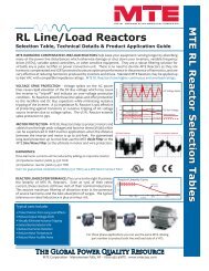
High-Efficiency Yanmar GHP Dramatically Reduces<br />
CO2 Emissions<br />
Estimate CO2 Reduction for 300 HP (30 HP x 10 units) Installation Running on Natural Gas or Propane Gas<br />
Annual reduction in CO2<br />
emissions of around<br />
55 t (Natural gas)<br />
43 t (Propane gas)<br />
Natural gas<br />
This is equivalent to the<br />
annual CO2 adsorption power* of<br />
Around 3,900<br />
Japanese cedar trees.<br />
APFs for Individual <strong>H1</strong> <strong>Series</strong> Outdoor Units<br />
(Year-Round Power Consumption Efficiency)<br />
Models: Standard type<br />
Area: Tokyo, Japan<br />
Application: Office-use<br />
2.05<br />
2.13<br />
Comparison of Annual CO2 Emissions<br />
EHP<br />
Model with APF<br />
of 4.0<br />
1.97<br />
2.13<br />
Equivalent HP 16 20 25 30<br />
<strong>H1</strong> series<br />
YNZP850<strong>H1</strong><br />
* A single Japanese cedar can adsorb around 14 kg of CO2 per year.<br />
Source: Report on using the adsorption power of greenery to prevent global warming by the Forestry Agency of the Japanese Ministry of the Environment.<br />
Conditions for Estimate<br />
• Indoor units<br />
50 Hz P140 4-way cassette model x 6 units<br />
The units are part of an office system operated in Tokyo, Japan.<br />
• Outdoor units<br />
30 HP GHP YNZP850<strong>H1</strong> model x 10 units<br />
APF: 2.14 Total annual load: 766,730 kWh; Estimated annual gas<br />
volume: 335,050 kWh; Annual power consumption: 23,700 kWh<br />
The APF, total annual load, estimated annual gas volume, and annual<br />
power consumption are calculated based on JIS B 8627.<br />
• APF: 4.0 Annual power consumption: 191,680 kWh<br />
(The same total annual load as for a GHP system is used, and the value is<br />
Environmentally Friendly 2<br />
High-Efficiency, High-APF GHP Achieves<br />
Major Energy Savings<br />
Propane gas<br />
Natural gas<br />
41% less<br />
Propane gas<br />
33% less<br />
This is equivalent to the<br />
annual CO2 Adsorption Power* of<br />
Around 3,100<br />
Japanese cedar trees.<br />
back-calculated from the APF for an EHP system.)<br />
• CO2 emission coefficient for electric power: 0.69 kg-CO2/kWh<br />
Interim Report by the Goal Achievement Scenario Subcommittee of the<br />
Global Environmental Section of the Central Environmental Council.<br />
Environmental report guidelines for FY2007 issued by Japan’s Ministry of<br />
the Environment.<br />
• CO2 emission coefficient for Natural gas: 0.0506 kg-CO2/MJ,<br />
Propane gas: 0.0598 kg-CO2/MJ<br />
Manual for the calculation and reporting of greenhouse gas emissions<br />
issued by Japan’s Ministry of the Environment and Ministry of <strong>Eco</strong>nomy,<br />
Trade and Industry in June 2007.<br />
Top GHP<br />
industry<br />
values<br />
for all<br />
models* 1<br />
1.75 * 2<br />
EHP<br />
APF 4.73-eqivalent model<br />
*1 Based on Yanmar research as of December 2007.<br />
*2 Based on incoming electrical generation efficiency of 0.369.
YNMP140G1 P140<br />
14 kW<br />
Specifications<br />
YNMP180G1 P180<br />
18 kW<br />
YNZP280<strong>H1</strong><br />
28 kW<br />
P280<br />
YNZP355<strong>H1</strong><br />
35.5 kW<br />
Model Unit YNMP140G1 YNMP180G1 YNZP280<strong>H1</strong> YNZP355<strong>H1</strong><br />
(14 kW)<br />
(18 kW)<br />
(28 kW)<br />
(35.5 kW)<br />
Capacity Cooling capacity kW 14.0 18.0 28.0 35.5<br />
Heating capacity kW 16.0 20.0 31.5 40.0<br />
Low-temp. heating kW 17.0 21.2 33.5 42.5<br />
Cold-weather heating kW 17.0 21.2 33.5 42.5<br />
Dimensions Height mm 1,740 2,170<br />
Width mm 1,100 1,690<br />
Depth mm 500 800<br />
Weight kg 380 735<br />
Indoor units connection Minimum total capacity of indoor units kW 7.0 9.0 14.0 17.8<br />
Maximum total capacity of indoor units kW 18.2 23.4 36.4 46.1<br />
Capacity of smallest indoor unit kW 2.2<br />
Maximum no. of units connectable – 8 10 16 20<br />
Electrical characteristics Power supply V Single phase 200 V<br />
Frequency Hz 50<br />
Operating current Cooling A 2.02 2.45 4.06 4.56<br />
Heating A 2.12 2.63 3.75 4.25<br />
Power consumption Cooling kW 0.38 0.47 0.65 0.73<br />
Heating kW 0.39 0.50 0.60 0.68<br />
Fuel consumption<br />
Natural gas HHV<br />
Cooling<br />
Heating<br />
kW<br />
kW<br />
11.8<br />
11.2<br />
14.2<br />
13.7<br />
21.6<br />
22.8<br />
25.4<br />
26.2<br />
LPG (Propane) HHV Cooling kW 11.8 14.2 21.6 25.4<br />
Heating kW 11.2 13.7 22.8 26.2<br />
Gas engine Manufacturer – YANMAR<br />
Rated Output kW 3.75 4.80 6.2 7.9<br />
Specified lubricant – Yanmar genuine GHP oil<br />
Cooling water Specified coolant – Yanmar genuine LLC (for GHP)<br />
Freezing temp. ˚C –35<br />
Sound pressure level Normal mode dB (A) 48 52 54 56<br />
Quiet mode dB (A) 45 49 51 53<br />
Fans Type – Propeller fan<br />
Number of units – 1 2<br />
Rated air flow m3/min 88 113 320 340<br />
Motor output W 170 x 1 370 x 2<br />
Refrigerant Type – R410A<br />
Charge kg 7.4 8.4 11.8<br />
Piping Refrigerant gas pipe mm 15.9 19.1 22.2 25.4<br />
Refrigerant liquid pipe mm 9.5 12.7<br />
Fuel gas pipe – R1/2 R3/4<br />
Exhaust vent (Outside dia.) mm 120 60.5<br />
Drain pipe for exhaust mm 16 (Outside dia.) 15 (Inside dia.)<br />
Allowable refrigerant piping length (Equivalent length/Real length) m 72/60 190/165<br />
Allowable height difference between Above outdoor units m 30 50<br />
indoor and outdoor units<br />
Below outdoor units m 30 50<br />
Allowable height difference between indoor units m 15<br />
External coating colour (Munsell no.)<br />
Yanmar warm ivory (5Y7.5/1)<br />
Measurement conditions<br />
1. Capacities, electrical characteristics and fuel consumptions are calculated for a standard indoor/outdoor unit combination<br />
with a 7.5 m piping length and 0 m level difference.<br />
Cooling capacity<br />
27 °CDB / 19 °CWB indoor suction air temp.<br />
35 °CDB outdoor suction air temp.<br />
Heating capacity<br />
20 °CDB indoor suction air temp.<br />
7 °CDB / 6 °CWB outdoor suction air temp.<br />
Low-temp heating capacity<br />
20 °CDB indoor suction air temp.<br />
2 °CDB / 1 °CWB outdoor suction air temp.<br />
Cold-weather heating capacity<br />
20 °CDB indoor suction air temp.<br />
-7 °CDB / -8 °CWB outdoor suction air temp.<br />
P355<br />
2. Sound pressure levels are measured at a height of 1.5m, 1 m from the front of the outdoor unit. These are anechoic<br />
conversion values. These values are normally somewhat higher during actual operation as a result of ambient<br />
conditions.<br />
3. Gas consumptions (m 3 N/h) are calculated as follows:<br />
Gas consumption (m3N/h) = Fuel consumption (kW) / HHV of gas (kWh/m 3 N)<br />
4. Specifications are subject to change without notice due to product improvements.
Outdoor Unit Lineup<br />
ANZP450<strong>H1</strong><br />
45 kW<br />
Specifications<br />
Model<br />
Capacity<br />
Hot water recovery<br />
Dimensions<br />
Weight<br />
Indoor units connection<br />
Electrical characteristics<br />
Fuel consumption LHV<br />
Gas engine<br />
Specified lubricant<br />
Cooling water<br />
Sound pressure level<br />
Fans<br />
Refrigerant<br />
Piping<br />
ANZP560<strong>H1</strong><br />
56 kW<br />
P450 P560<br />
Cooling capacity<br />
Heating capacity<br />
Low-temp. heating<br />
Cold-weather heating<br />
Quantity of exhaust heat recovery<br />
Hot water temperature Outlet<br />
Hot water volume flowrate<br />
Height<br />
Width<br />
Depth<br />
Total capacity of indoor units<br />
Minimum capacity of indoor units type<br />
Maximum no. of units connectable<br />
Power supply<br />
Frequency<br />
Operating current<br />
Power consumption<br />
Natural gas<br />
LHV<br />
Propane gas<br />
LHV<br />
Manufacturer<br />
Model<br />
Cooling<br />
Heating<br />
Cooling<br />
Heating<br />
Cooling<br />
Heating<br />
Cooling<br />
Heating<br />
Specified coolant<br />
Freezing temp.<br />
Normal mode<br />
Quiet mode<br />
Type<br />
Number of units<br />
Rated air flow<br />
Motor output<br />
Type<br />
Charge<br />
Refrigerant gas pipe<br />
Refrigerant liquid pipe<br />
Fuel gas pipe<br />
Exhaust vent (Outside dia.)<br />
Drain pipe (Inside dia.)<br />
Hot water pipe<br />
Inlet<br />
Outlet<br />
Allowable refrigerant piping length (Equivalent length/Real length)<br />
Total piping length<br />
Allowable piping length (after the first branch)<br />
Allowable height difference between Above outdoor units<br />
indoor and outdoor units<br />
Below outdoor units<br />
Allowable height difference between indoor units<br />
External coating colour (Munsell no.)<br />
ANZP710<strong>H1</strong><br />
71 kW<br />
Unit<br />
kW<br />
kW<br />
kW<br />
kW<br />
kW<br />
˚C<br />
L/min<br />
mm<br />
mm<br />
mm<br />
kg<br />
%<br />
–<br />
–<br />
V<br />
Hz<br />
A<br />
A<br />
kW<br />
kW<br />
kW<br />
kW<br />
kW<br />
kW<br />
–<br />
–<br />
–<br />
–<br />
˚C<br />
dB (A)<br />
dB (A)<br />
–<br />
–<br />
m 3 /min<br />
W<br />
–<br />
kg<br />
mm<br />
mm<br />
–<br />
mm<br />
mm<br />
–<br />
–<br />
m<br />
m<br />
m<br />
m<br />
m<br />
m<br />
Measurement conditions<br />
1. Capacities, electrical characteristics and fuel consumptions are calculated for a standard indoor/outdoor<br />
unit combination with a 7.5 m piping length and 0 m level difference.<br />
Cooling capacity<br />
27 CDB / 19 CWB indoor suction air temp.<br />
35 CDB outdoor suction air temp.<br />
Heating capacity<br />
20 CDB indoor suction air temp.<br />
7 CDB / 6 CWB outdoor suction air temp.<br />
Standard GHP Hot Water Recovery GHP<br />
Low-temp. heating capacity<br />
20 CDB indoor suction air temp.<br />
2 CDB / 1 CWB outdoor suction air temp.<br />
Cold-weather heating capacity<br />
20 CDB indoor suction air temp.<br />
-7 CDB / -8 CWB outdoor suction air temp.<br />
ANZP450<strong>H1</strong><br />
(45 kW)<br />
45.0<br />
50.0<br />
53.0<br />
53.0<br />
820<br />
26<br />
4.12<br />
3.85<br />
0.90<br />
0.84<br />
30.9<br />
30.7<br />
30.9<br />
30.7<br />
57<br />
54<br />
360<br />
12.7<br />
P710<br />
1,690<br />
ANZP560<strong>H1</strong><br />
(56 kW)<br />
56.0<br />
63.0<br />
67.0<br />
67.0<br />
840<br />
32<br />
4.99<br />
4.76<br />
1.09<br />
1.04<br />
42.6<br />
41.9<br />
41.4<br />
40.7<br />
58<br />
55<br />
380<br />
ANZP850<strong>H1</strong><br />
85 kW<br />
15.9<br />
ANZP710<strong>H1</strong><br />
(71 kW)<br />
71.0<br />
80.0<br />
84.0<br />
78.0<br />
2,170<br />
800<br />
1,020<br />
50 to 130<br />
P22<br />
40<br />
Single phase 240 V<br />
50<br />
6.71<br />
6.30<br />
1.45<br />
1.36<br />
54.0<br />
53.6<br />
50.8<br />
50.4<br />
YANMAR<br />
–35<br />
61<br />
58<br />
Propeller fan<br />
540<br />
P850<br />
AHZP850<strong>H1</strong><br />
85 kW<br />
ANZP850<strong>H1</strong><br />
(85 kW)<br />
85.0<br />
95.0<br />
95.0<br />
95.0<br />
2,100<br />
48<br />
7.60<br />
6.91<br />
1.66<br />
1.51<br />
60.9<br />
59.7<br />
60.6<br />
59.5<br />
3GPH88<br />
4GPH88<br />
Yanmar genuine GHP oil<br />
Yanmar genuine LLC (for GHP) Yanmar genuine LLC (for CP)<br />
2<br />
370 x 2<br />
28.6<br />
–<br />
–<br />
–<br />
–<br />
–<br />
R410A<br />
11.8<br />
R3/4<br />
60.5<br />
15<br />
200/170<br />
640 or less<br />
90<br />
50<br />
50<br />
15<br />
Yanmar warm ivory (5Y7.5/1)<br />
62<br />
59<br />
370 x 3<br />
31.8<br />
19.1<br />
3<br />
570<br />
AHZP850<strong>H1</strong><br />
(85 kW)<br />
85.0<br />
95.0<br />
95.0<br />
95.0<br />
30.0<br />
70.0<br />
43.0<br />
1,040<br />
48<br />
7.60<br />
6.91<br />
1.66<br />
1.51<br />
60.9<br />
59.7<br />
60.6<br />
59.5<br />
62<br />
59<br />
Rc1<br />
Rc1<br />
P850<br />
2. Sound pressure levels are measured at a height of 1.5 m, 1 m from the front of the outdoor unit. These<br />
are anechoic conversion values. These values are normally somewhat higher during actual operation<br />
as a result of ambient conditions.<br />
3. Gas consumptions (m 3 N/h) are calculated as follows:<br />
Gas consumption (m3N/h) = Fuel consumption (kW) / LHV of gas (kWh/m 3 N)<br />
4. Water heating is only available in the cooling mode.<br />
Water heating capacity is dependent upon the operating conditions.<br />
5. Specifications are subject to change without notice due to product improvements.
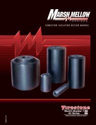
Hot Water Recovery GHP<br />
GHP: Gas Powered Air Conditioning Unit with Hot Water Recovery<br />
Water heating function available in cooling mode.<br />
Operation utilises heat recovered from the gas engine.<br />
Higher Performance (COP)<br />
System Design<br />
Models available for natural gas and LPG.<br />
P850 Model<br />
GHP Outdoor Unit<br />
Compressor<br />
Gas<br />
Engine<br />
Multi-split Type<br />
Air-conditioning<br />
Hot Water<br />
ON/OFF<br />
Signal<br />
* Water pumps, storage tank, water heater, etc. are to be locally supplied.<br />
AHZP850<strong>H1</strong>, PHZP850<strong>H1</strong><br />
Heat Exchanger<br />
Water Pump<br />
Storage<br />
Tank<br />
Water Supply<br />
P112 P140 P71 P140<br />
Controller OFF<br />
ON ON ON<br />
1. Every indoor unit or group can be individually operated and set.<br />
2. Different configuration and capacity indoor units can be connected.<br />
3. The total capacity of connectable indoor units is 50 to 130% of the outdoor unit capacity.<br />
160<br />
86<br />
20-24 long hole<br />
20<br />
fig D<br />
outdoor unit fixture<br />
320<br />
11<br />
fig A<br />
A<br />
7<br />
D<br />
550<br />
2100<br />
front side<br />
1000<br />
(anchor bolt pitch)<br />
10<br />
tap<br />
900<br />
953 240<br />
12<br />
(fan guard projection)<br />
2170<br />
26<br />
(outlet projection)<br />
50<br />
860<br />
(anchor bolt pitch)<br />
125<br />
186<br />
Water Pump<br />
9<br />
8<br />
4<br />
135<br />
fig B<br />
800<br />
12 13<br />
Water<br />
Heater<br />
No Description Remarks<br />
1 Refrigerant liquid piping connector ø 19.1<br />
2 Refrigerant gas piping connentor ø 31.8<br />
3 Exhaust drain piping connector ø 15 (inside dia.)<br />
4 Fuel gas piping connector R3/4 (external thread)<br />
5 Wiring port ø 28 Grommet<br />
6 Air inlet<br />
7 Hour meter<br />
8 Cooling water tank level<br />
9 Cooling water filling port cover<br />
10 Exhaust vent ø 60.5 (outside dia.)<br />
11 Drain condensate piping connector ø 15 (inside dia.)<br />
12 Hot water inlet<br />
Rc1 (internal thread)<br />
13 Hot water outlet<br />
Rc1 (internal thread)<br />
6<br />
B 3<br />
1270 C<br />
back side<br />
145<br />
140<br />
844<br />
924<br />
2 1 5<br />
fig C<br />
105<br />
165<br />
265<br />
125<br />
185
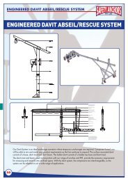
4-Way Cassette Type<br />
PCAP-FSN2<br />
Extremely Quiet Operation and Elegant Design Matching Any Interior<br />
Industry-leading Low Sound<br />
Pressure Level<br />
Super low sound pressure level, 30 dB<br />
(A) (P28 to P56: at HIGH speed<br />
operation) is achieved by using a new<br />
DC fan motor and vibration-proof<br />
structure which protects the turbo fan<br />
from abnormal sound.<br />
Newly Developed “Wide Air Flow<br />
Wing”<br />
• The "wide air flow wing" swinging louver<br />
design ensures air is distributed to all<br />
four edges of the panel. This provides an<br />
outstandingly comfortable air-conditional<br />
environment without temperature<br />
irregularities.<br />
Conventional model<br />
New model<br />
Air flow is provided<br />
only linearly to the<br />
air outlet, thus airconditioned<br />
flow is<br />
not uniformity.<br />
Air flow is provided<br />
in widen toward the<br />
end, thus airconditioned<br />
flow<br />
can be distributed<br />
in all directions.<br />
• The Shutter function is newly adopted to<br />
conceal the air outlets with the louvers<br />
when operation is stopped. The louvers<br />
cover the air outlet horizontally<br />
providing a neat appearance.<br />
Remote Control Switch<br />
PLPAR<br />
Wireless Remote Controller<br />
PC-LH3A<br />
Remote control switch and wireless<br />
remote controller are both options.<br />
Air is distributed to all<br />
four edges of panel.<br />
IN Operation OFF Operation<br />
Simplified Panel Wiring<br />
The panel wiring connector has been<br />
shifted to inside the air inlet grille. No<br />
need to open the electrical box cover for<br />
panel wiring work.
Specifications<br />
Model PCAP28FSN2 PCAP45FSN2 PCAP56FSN2 PCAP71FSN2 PCAP80FSN2 PCAP112FSN2 PCAP140FSN2<br />
(P28)<br />
(P45)<br />
(P56)<br />
(P71)<br />
(P80)<br />
(P112)<br />
(P140)<br />
Cooling (kW) 2.8<br />
4.5<br />
5.6<br />
7.1<br />
8.0<br />
11.2<br />
14.0<br />
Capacity Heating (kW) 3.2<br />
5.0<br />
6.3<br />
8.0<br />
9.0<br />
12.5<br />
16.0<br />
Low temp.<br />
heating (kW) 3.4<br />
5.3<br />
6.7<br />
8.5<br />
9.5<br />
13.2<br />
17.0<br />
Dimensions Height (mm) 248 (37)<br />
248 (37) 248 (37) 248 (37)<br />
298 (37)<br />
298 (37) 298 (37)<br />
Unit (Standard<br />
panel)<br />
Width<br />
Depth<br />
(mm)<br />
(mm)<br />
840 (950)<br />
840 (950)<br />
840 (950)<br />
840 (950)<br />
840 (950)<br />
840 (950)<br />
840 (950)<br />
840 (950)<br />
840 (950)<br />
840 (950)<br />
840 (950)<br />
840 (950)<br />
840 (950)<br />
840 (950)<br />
(kg) 23 (6)<br />
23 (6)<br />
24 (6)<br />
24 (6)<br />
26 (6)<br />
29 (6)<br />
29 (6)<br />
Power supply<br />
Power Cooling (kW) 0.03<br />
0.03<br />
0.04<br />
0.06<br />
0.07<br />
0.13<br />
0.16<br />
consumption<br />
Heating (kW) 0.02<br />
0.02<br />
0.03<br />
0.05<br />
0.06<br />
0.12<br />
0.15<br />
Running Cooling (A) 0.15<br />
0.15<br />
0.20<br />
0.29<br />
0.34<br />
0.62<br />
0.78<br />
current<br />
Heating (A) 0.10<br />
0.10<br />
0.14<br />
0.24<br />
0.29<br />
0.59<br />
0.74<br />
Power Cooling (%) 86<br />
86<br />
85<br />
86<br />
86<br />
88<br />
86<br />
factor<br />
Heating (%) 85<br />
85<br />
87<br />
86<br />
86<br />
85<br />
85<br />
Air filter<br />
Type<br />
Motor output (kW) 0.056<br />
0.056<br />
0.056<br />
0.056<br />
0.056<br />
0.124<br />
0.124<br />
H (m 13<br />
15<br />
16<br />
20<br />
21<br />
32<br />
34<br />
Air flow<br />
amount<br />
M<br />
12<br />
13.5<br />
14<br />
17<br />
18<br />
28<br />
29<br />
L<br />
11<br />
12<br />
12<br />
15<br />
15<br />
24<br />
25<br />
External static pressure<br />
Sound pressure<br />
level<br />
H<br />
M<br />
30<br />
28<br />
30<br />
28<br />
30<br />
28<br />
32<br />
30<br />
32<br />
30<br />
38<br />
35<br />
39<br />
37<br />
L<br />
27<br />
27<br />
27<br />
28<br />
28<br />
33<br />
35<br />
Refrigerant<br />
(Flare<br />
connections)<br />
Liquid<br />
Gas<br />
6.4<br />
12.7<br />
6.4<br />
12.7<br />
6.4<br />
12.7<br />
9.5<br />
15.9<br />
9.5<br />
15.9<br />
9.5<br />
15.9<br />
9.5<br />
15.9<br />
Drain piping<br />
Colour Munsell number<br />
Standard panel Model name<br />
Remote controller Model name<br />
3 /min.)<br />
(m3 /min.)<br />
(m3 Weight Unit (Panel)<br />
Single phase, 240 V, 50 Hz<br />
Polypropylene, mould proof<br />
Single air inlet, multi-blades fan (turbo fan)<br />
/min.)<br />
(Pa)<br />
(dB (A))<br />
(dB (A))<br />
(dB (A))<br />
(mm)<br />
(mm)<br />
VP25, external<br />
Silky white (2.5Y8.9/1)<br />
PPCN23WA<br />
PLPAR<br />
(1) The rated capacity is the system performance by a standard indoor/outdoor unit combination with a 7.5 m piping length and 0 m level difference.<br />
Cooling capacity: 27 CDB/19 CWB indoor suction air temp., 35 CDB outdoor suction air temp. Heating capacity: 20 CDB indoor suction air temp., 7 CDB/6 CWB outdoor<br />
suction air temp. Low-temp. heating capacity: 20 CDB indoor suction air temp., 2 CDB/1 CWB outdoor suction air temp.<br />
(2) The sound pressure level is the value measured at a height of 1.5 m, 1 m from the front of the unit and calculated with zero echo considered. When the unit is actually installed,<br />
the sound pressure level will be affected by ambient noise and echoes and will normally be more than the values specified above.<br />
(3) The values above are for a single indoor unit.<br />
(4) Capacity characteristics vary according to the combination of indoor and outdoor units.<br />
(5) Specifications are subject to change without notice due to product improvements.<br />
Electrical characteristics 50 Hz<br />
Fan<br />
Piping<br />
connection<br />
Dimensions<br />
P28 to P140<br />
25 (Liquid piping)<br />
24 (Drain piping)<br />
18 (Gas piping)<br />
20<br />
Electric parts box<br />
860 to 910 (Ceiling opening)<br />
840<br />
760<br />
(Suspension bolt)<br />
14<br />
110 (Gas piping)<br />
180 (Liquid piping)<br />
710 (Drain piping)<br />
4-Suspension bolt M10 or W3/8<br />
(must be obtained locally)<br />
Refrigerant liquid pipe connection port<br />
Refrigerant gas pipe connection port (with b copper pipe flare nut)<br />
(with c copper pipe flare nut) Drain pipe connection port<br />
(PVC pipe, VP25 pipe connection)<br />
127 (Liquid piping)<br />
118 (Drain piping)<br />
102 (Gas piping)<br />
36<br />
31<br />
A<br />
Wiring connection port ( 32.5 hole)<br />
Wiring connection port<br />
(30 x 39 long hole) (for cable)<br />
Remote controller<br />
4-14x26 Long hole<br />
(for suspension)<br />
120<br />
20<br />
760<br />
(Suspension bolt)<br />
840<br />
860 to 910 (Ceiling opening)<br />
102<br />
a<br />
37<br />
20<br />
Optional panel<br />
Twist pair cable (0.75mm<br />
Air inlet grille Air outlet<br />
(four directions)<br />
2 or more)<br />
(must be obtained locally)<br />
950<br />
Viewed from A<br />
Connection position<br />
for fresh air suction duct adaptor<br />
Air suction grille opening/closing<br />
Dimensions correspondence chart<br />
Size Model P28 to P56 P71 P80 P112 to P140<br />
a<br />
b<br />
c<br />
500<br />
248<br />
6.4<br />
12.7<br />
100<br />
100<br />
Pipe connection port<br />
Service space<br />
500<br />
248<br />
9.5<br />
15.9<br />
100<br />
100<br />
298<br />
9.5<br />
298<br />
9.5<br />
15.9 15.9<br />
100<br />
500 3000 500<br />
100<br />
(Unit: mm)<br />
Pipe connection port Pipe connection port<br />
For single unit installation For two unit installation at the same place
In-the-Ceiling Type<br />
PDAP-FSN2<br />
Remote Control Switch<br />
PLPAR<br />
Wireless Remote Controller<br />
PC-LH3A<br />
Remote control switch and wireless<br />
remote controller are both options.<br />
Quiet Operation and Low Height Design for Limited Space Inside of the Ceiling<br />
Broader Range of External Static Pressure.<br />
Flexibly Supports a Wide Range of Installation<br />
Conditions at Site, e.g. Longer Ducts.<br />
In addition to the standard Hi-Me-Lo, the speed-up tap<br />
can be set by remote control. Available for external static<br />
pressure of up to 80 Pa for P22 to P71 and 170 Pa for<br />
P90 to P140.<br />
Space-saving Design<br />
Less than 270 mm in height, this unit can fit into practically<br />
any previously existing false ceiling or formerly ducted<br />
space without substantial modification (P22 to P71).<br />
(P22 to P71)<br />
270mm<br />
Minimum 5mm<br />
False Ceiling<br />
Dimensions correspondence chart<br />
Size<br />
Model<br />
A<br />
B<br />
C<br />
D<br />
E<br />
F<br />
G<br />
H<br />
I<br />
J<br />
K<br />
L<br />
Size<br />
Model<br />
M<br />
N<br />
P<br />
Q<br />
R<br />
S<br />
T<br />
U<br />
V<br />
W<br />
X<br />
Y<br />
P22<br />
650<br />
730<br />
1<br />
300<br />
215<br />
553<br />
583<br />
6.35<br />
12.7<br />
70<br />
92<br />
10<br />
P28 P45 P56<br />
650<br />
730<br />
1<br />
300<br />
215<br />
553<br />
583<br />
6.35<br />
12.7<br />
70<br />
92<br />
10<br />
650<br />
730<br />
1<br />
300<br />
215<br />
553<br />
583<br />
6.35<br />
12.7<br />
70<br />
92<br />
10<br />
900<br />
980<br />
2<br />
600<br />
190<br />
803<br />
833<br />
6.35<br />
15.88<br />
77<br />
92<br />
12<br />
P71 P90<br />
900<br />
980<br />
2<br />
600<br />
190<br />
803<br />
833<br />
9.53<br />
15.88<br />
77<br />
95<br />
12<br />
900<br />
980<br />
2<br />
600<br />
190<br />
803<br />
833<br />
9.53<br />
15.88<br />
78<br />
95<br />
12<br />
P112 P140<br />
900<br />
980<br />
2<br />
600<br />
190<br />
803<br />
833<br />
9.53<br />
15.88<br />
81<br />
95<br />
12<br />
1,300<br />
1,380<br />
3<br />
900<br />
240<br />
1,203<br />
1,233<br />
9.53<br />
15.88<br />
81<br />
95<br />
14<br />
P22 P28 P45 P56 P71 P90 P112 P140<br />
676 676 676 676 676 756 756 756<br />
720 720 720 720 720 800 800 800<br />
23 23 23 23 23 103 103 103<br />
270 270 270 270 270 350 350 350<br />
182 182 182 182 182 204 204 204<br />
222 222 222 222 222 244 244 244<br />
43 43 43 43 43 123 123 123<br />
220 220 220 220 220 300 300 300<br />
100 100 100 100 100 140 140 140<br />
200 200 200 200 200 280 280 280<br />
226 226 226 226 226 306 306 306<br />
For the Y dimensions, install the drain pipe at a height that ensures sufficient slope.
Specifications<br />
Model PDAP22FSN2 PDAP28FSN2 PDAP45FSN2 PDAP56FSN2 PDAP71FSN2 PDAP90FSN2 PDAP112FSN2 PDAP140FSN2<br />
(P22)<br />
(P28)<br />
(P45)<br />
(P56)<br />
(P71)<br />
(P90)<br />
(P112)<br />
(P140)<br />
Cooling (kW) 2.2<br />
2.8<br />
4.5<br />
5.6<br />
7.1<br />
9.0<br />
11.2<br />
14.0<br />
Capacity Heating (kW) 2.5<br />
3.2<br />
5.0<br />
6.3<br />
8.0<br />
10.0<br />
12.5<br />
16.0<br />
Low temp.<br />
heating (kW) 2.8<br />
3.4<br />
5.3<br />
6.7<br />
8.5<br />
10.6<br />
13.2<br />
17.0<br />
Dimensions Height (mm) 270<br />
270<br />
270<br />
270<br />
350<br />
350<br />
350<br />
350<br />
Unit (Standard<br />
panel)<br />
Width<br />
Depth<br />
(mm)<br />
(mm)<br />
650 + 75<br />
720<br />
650 + 75<br />
720<br />
650 + 75<br />
720<br />
900 + 75<br />
720<br />
900 + 75<br />
720<br />
900 + 75<br />
800<br />
900 + 75<br />
800<br />
1300 + 75<br />
800<br />
(kg) 26<br />
26<br />
26<br />
35<br />
35<br />
46<br />
46<br />
58<br />
Power supply<br />
0.11<br />
0.11<br />
0.15<br />
0.15<br />
0.15<br />
0.31<br />
0.31<br />
0.46<br />
0.11<br />
0.11<br />
0.15<br />
0.15<br />
0.15<br />
0.31<br />
0.31<br />
0.46<br />
0.51<br />
0.51<br />
0.69<br />
0.69<br />
0.69<br />
1.44<br />
1.44<br />
2.13<br />
0.51<br />
0.51<br />
0.69<br />
0.69<br />
0.69<br />
1.44<br />
1.44<br />
2.13<br />
90<br />
90<br />
90<br />
90<br />
90<br />
90<br />
90<br />
90<br />
90<br />
90<br />
90<br />
90<br />
90<br />
90<br />
90<br />
90<br />
Air filter<br />
Type<br />
Motor output (kW) 0.06<br />
0.06<br />
0.06<br />
0.075<br />
0.075<br />
0.15<br />
0.29<br />
0.29<br />
H (m 8<br />
8<br />
13<br />
15<br />
16<br />
25<br />
27<br />
37<br />
Air flow<br />
amount<br />
M<br />
7<br />
7<br />
11<br />
13<br />
14<br />
21<br />
23<br />
31<br />
L<br />
6<br />
6<br />
9<br />
11<br />
12<br />
17<br />
19<br />
25<br />
External static pressure<br />
50 (L: 30 H: 80)<br />
120 (L: 60 H: 170)<br />
Sound pressure<br />
level<br />
H<br />
M<br />
36<br />
34<br />
36<br />
34<br />
36<br />
34<br />
36<br />
34<br />
37<br />
35<br />
43<br />
40<br />
45<br />
42<br />
46<br />
43<br />
L<br />
32<br />
32<br />
32<br />
32<br />
33<br />
36<br />
38<br />
39<br />
Refrigerant<br />
(Flare<br />
connections)<br />
Liquid<br />
Gas<br />
6.4<br />
12.7<br />
6.4<br />
12.7<br />
6.4<br />
12.7<br />
6.4<br />
12.7<br />
9.5<br />
15.9<br />
9.5<br />
15.9<br />
9.5<br />
15.9<br />
9.5<br />
15.9<br />
Drain piping<br />
Colour Munsell number<br />
Remote controller Model name<br />
3 /min.)<br />
(m3 /min.)<br />
(m3 Weight Unit (Panel)<br />
Single phase, 240 V, 50 Hz<br />
Power Cooling (kW)<br />
consumption<br />
Heating (kW)<br />
Running Cooling (A)<br />
current<br />
Heating (A)<br />
Power Cooling (%)<br />
factor<br />
Heating (%)<br />
Polypropylene, mould proof<br />
Sirocco fan<br />
/min.)<br />
(Pa)<br />
(dB (A))<br />
(dB (A))<br />
(dB (A))<br />
(mm)<br />
(mm)<br />
VP25, external<br />
Galvanised steel sheet<br />
PLPAR<br />
(1) The rated capacity is the system performance by a standard indoor/outdoor unit combination with a 7.5 m piping length and 0 m level difference.<br />
Cooling capacity: 27 CDB/19 CWB indoor suction air temp., 35 CDB outdoor suction air temp. Heating capacity: 20 CDB indoor suction air temp., 7 CDB/6 CWB outdoor<br />
suction air temp. Low-temp. heating capacity: 20 CDB indoor suction air temp., 2 CDB/1 CWB outdoor suction air temp.<br />
(2) The sound pressure level is the value measured at a height of 1.5 m, 1 m from the front of the unit and calculated with zero echo considered. When the unit is actually installed,<br />
the sound pressure level will be affected by ambient noise and echoes and will normally be more than the values specified above.<br />
(3) The values above are for a single indoor unit.<br />
(4) Capacity characteristics vary according to the combination of indoor and outdoor units.<br />
(5) Specifications are subject to change without notice due to product improvements.<br />
Electrical characteristics 50 Hz<br />
Fan<br />
Piping<br />
connection<br />
Dimensions (Unit: mm)<br />
30<br />
P22 to P140<br />
20<br />
22<br />
N<br />
M<br />
30<br />
20 22<br />
220<br />
P<br />
40<br />
48.5<br />
E<br />
E<br />
300<br />
B<br />
A<br />
C x300=<br />
D<br />
(Circumference of flange)<br />
4-40 x 12 long hole<br />
(for suspension)<br />
Twist pair cable (0.75 mm2 L -ø6<br />
or more)<br />
(must be obtained locally)<br />
Remote controller<br />
120<br />
300<br />
L -ø6<br />
C x 300=<br />
D<br />
A<br />
Air outlet (front side)<br />
(Circumference of flange)<br />
Refrigerant gas pipe connection port<br />
75 (Electric box) (ø I copper tube with flare nut)<br />
Drain pipe connection port<br />
Refrigerant liquid pipe connection port (VP25)<br />
(ø H copper tube with flare nut)<br />
U 45<br />
F<br />
97<br />
Q<br />
T 2x90=180<br />
90<br />
S<br />
R<br />
23<br />
J (Refrigerant gas pipe connection position)<br />
90 (Drain pipe connection position)<br />
K (Refrigerant liquid pipe connection position)<br />
Operation circuit<br />
connection port<br />
Power supply<br />
connection port<br />
600<br />
1000<br />
1000<br />
V<br />
35<br />
2x V = W<br />
246 (Refrigerant liquid pipe connection position)<br />
321 (Refrigerant gas pipe connection position)<br />
377 (Drain pipe connection position)<br />
Top side<br />
Electric box<br />
(Rear side)<br />
Inspection port (For the M dimensions, install the drain pipe<br />
at a height that ensures sufficient slope.)<br />
( 450 or more)<br />
(Front (130)<br />
Create a section that will function as an<br />
side)<br />
opening for the lower surface of the indoor<br />
unit. This opening should be made in a<br />
location where the ceiling panel will not easily<br />
detach but where the indoor unit itself can be<br />
600 or more<br />
removed.<br />
Top side Service space<br />
Y<br />
Air inlet<br />
G<br />
X<br />
22<br />
33.5<br />
Notes<br />
1. Take steps to prevent vibrations by using a canvas joint for the duct<br />
section and an anti-vibration hanger for the unit body. This will<br />
prevent vibrations from the unit body being transferred to the ceiling<br />
or mounting block.<br />
2. If the external static pressure is set too high for the ducts, the air<br />
speed will increase significantly, causing a large amount of noise<br />
and spraying of water. In this case, install a damper to regulate the<br />
air volume or change the static pressure adjustment so that the<br />
external static pressure is equal to the pressure loss for the ducts.<br />
3. Use the companion flanges included with the product as the duct<br />
connection companion flanges for both the air intake and discharge<br />
sides.
15<br />
Ceiling Type<br />
PHAP-FSN2<br />
Quiet Operation, Easy Installation and Space-Saving Slim Design<br />
Amenity Improved by Auto-louver<br />
at Air Opening.<br />
The round, lower part of the air opening<br />
complements the gentle, quiet operation.<br />
The auto-louver in the upper part of the<br />
opening automatically controls upward<br />
and downward motion of air flow, while<br />
the grille serves as a shutter when<br />
stopped.<br />
While<br />
Stopped<br />
Downward<br />
Flow<br />
Horizontal<br />
Flow<br />
Auto-louver<br />
Noise and Vibration Drastically<br />
Reduced by Our Original Design.<br />
The large fan and improved resistance of<br />
the air flow path lower the r.p.m. of the<br />
blower, thus reducing noise and vibration.<br />
Improved Resistance of Air Flow Path<br />
Current Model<br />
Heat Exchanger<br />
New Model<br />
Fan Fan<br />
Heat Exchanger<br />
Remote Control Switch<br />
PLPAR<br />
Wireless Remote Controller<br />
PC-LH3A<br />
Remote control switch and wireless<br />
remote controller are both options.<br />
Simple Installation and<br />
Maintenance<br />
• Installation time is much shorter.<br />
*By 30% (Manufacturer’s comparison)<br />
• A long-life filter (mildew-proof) is fitted as<br />
standard. No maintenance is required<br />
for about 2,500 hours of operation.<br />
*For ordinary offices<br />
Each Part of the System is Fully<br />
Functional.<br />
The wireless light receiver kit (option) can<br />
be installed easily through the hole in the<br />
lower cover.
Specifications<br />
Power supply<br />
Air filter<br />
Power<br />
consumption<br />
Running<br />
current<br />
Power<br />
factor<br />
Model<br />
Capacity<br />
Cooling (kW)<br />
Heating (kW)<br />
Low temp.<br />
heating (kW)<br />
Dimensions Height (mm)<br />
Unit (Standard<br />
panel)<br />
Width<br />
Depth<br />
(mm)<br />
(mm)<br />
Weight Unit (Panel) (kg)<br />
Electrical characteristics 50 Hz<br />
Fan<br />
Cooling (kW)<br />
Heating (kW)<br />
Cooling (A)<br />
Heating (A)<br />
Cooling (%)<br />
Heating (%)<br />
Type<br />
Motor output (kW)<br />
H (m<br />
Air flow<br />
amount<br />
M<br />
L<br />
3 /min.)<br />
(m3 /min.)<br />
(m3 /min.)<br />
External static pressure (Pa)<br />
Sound pressure<br />
level<br />
H<br />
M<br />
(dB (A))<br />
(dB (A))<br />
L (dB (A))<br />
Refrigerant<br />
(Flare<br />
connections)<br />
Drain piping<br />
Liquid (mm)<br />
Gas (mm)<br />
Piping<br />
connection<br />
Colour Munsell number<br />
Remote controller Model name<br />
PHAP56FSN2<br />
(P56)<br />
5.6<br />
6.3<br />
6.7<br />
210<br />
1100<br />
670<br />
26<br />
0.09<br />
0.09<br />
0.42<br />
0.42<br />
89<br />
89<br />
0.035<br />
14<br />
12<br />
10<br />
41<br />
38<br />
35<br />
6.4<br />
12.7<br />
PHAP71FSN2<br />
(P71)<br />
7.1<br />
8.0<br />
8.5<br />
210<br />
1320<br />
670<br />
30<br />
0.12<br />
0.12<br />
0.57<br />
0.57<br />
88<br />
88<br />
0.050<br />
18<br />
15<br />
12<br />
41<br />
38<br />
35<br />
9.5<br />
15.9<br />
PHAP80FSN2<br />
(P80)<br />
8.0<br />
9.0<br />
9.5<br />
210<br />
1320<br />
670<br />
30<br />
Single phase, 240 V, 50 Hz<br />
0.12<br />
0.12<br />
0.57<br />
0.57<br />
88<br />
88<br />
Polypropylene, mould proof<br />
Sirocco fan<br />
0.050<br />
18<br />
15<br />
12<br />
41<br />
38<br />
35<br />
9.5<br />
15.9<br />
VP20, external<br />
Silky white (2.5Y8.9/1)<br />
PLPAR<br />
PHAP112FSN2<br />
(P112)<br />
11.2<br />
12.5<br />
13.2<br />
270<br />
1320<br />
670<br />
34<br />
Dimensions (Unit: mm)<br />
P56 to P140<br />
0.22<br />
0.22<br />
1.02<br />
1.02<br />
90<br />
90<br />
0.095<br />
25<br />
21<br />
18<br />
45<br />
42<br />
39<br />
9.5<br />
15.9<br />
PHAP140FSN2<br />
(P140)<br />
14.0<br />
16.0<br />
17.0<br />
270<br />
1580<br />
670<br />
42<br />
(1) The rated capacity is the system performance by a standard indoor/outdoor unit combination with a 7.5 m piping length and 0 m level difference.<br />
Cooling capacity: 27 CDB/19 CWB indoor suction air temp., 35 CDB outdoor suction air temp. Heating capacity: 20 CDB indoor suction air temp., 7 CDB/6 CWB outdoor<br />
suction air temp. Low-temp. heating capacity: 20 CDB indoor suction air temp., 2 CDB/1 CWB outdoor suction air temp.<br />
(2) The sound pressure level is the value measured at a height of 1.5 m, 1 m from the front of the unit and calculated with zero echo considered. When the unit is actually installed,<br />
the sound pressure level will be affected by ambient noise and echoes and will normally be more than the values specified above.<br />
(3) The values above are for a single indoor unit.<br />
(4) Capacity characteristics vary according to the combination of indoor and outdoor units.<br />
(5) Specifications are subject to change without notice due to product improvements.<br />
Air outlet<br />
Top-side cable<br />
connection hole<br />
27<br />
70<br />
148<br />
Top-side piping<br />
connection hole<br />
A<br />
B<br />
38 (Dimension of<br />
suspension bracket)<br />
Installation port of wireless remote<br />
controller signal receiving kit<br />
J<br />
110<br />
Air outlet<br />
92<br />
280 110<br />
670<br />
Twist pair cable (0.75 mm 2 or more)<br />
(must be obtained locally)<br />
Remote controller<br />
ø12 (Suspension bolt installation position)<br />
50 or less (Length<br />
of suspension bolt)<br />
E<br />
D<br />
70 C<br />
70<br />
Refrigerant liquid pipe G<br />
Refrigerant gas pipe F<br />
305<br />
Right-side piping connection<br />
hole (Knockout hole)<br />
118<br />
160<br />
Model<br />
Size<br />
A<br />
B<br />
C<br />
D<br />
E<br />
F<br />
G<br />
H<br />
I<br />
J<br />
K<br />
Refrigerant gas pipe<br />
H connection position 156 Drain pipe connection position (VP20)<br />
( F copper tube with flare nut) (for left-side draining)<br />
I<br />
Refrigerant liquid pipe<br />
connection position<br />
( G copper tube with flare nut)<br />
106<br />
135<br />
40<br />
12 52<br />
104<br />
130<br />
Rear-side piping<br />
connection cover<br />
Left-side piping connection<br />
hole (Knockout hole)<br />
74<br />
175<br />
K<br />
67<br />
1,000<br />
1,100<br />
960<br />
216<br />
210<br />
12.7<br />
6.4<br />
215<br />
200<br />
370<br />
370<br />
1,220<br />
1,320<br />
1,180<br />
216<br />
210<br />
15.9<br />
9.5<br />
205<br />
195<br />
370<br />
370<br />
1,220<br />
1,320<br />
1,180<br />
276<br />
270<br />
0.22<br />
0.22<br />
1.02<br />
1.02<br />
90<br />
90<br />
0.135<br />
33<br />
28<br />
23<br />
45<br />
42<br />
39<br />
9.5<br />
15.9<br />
Dimensions correspondence chart<br />
P56 P71 • 80 P112 P140<br />
Rear-side cable<br />
connection hole<br />
103<br />
* 40 or more<br />
Space required for<br />
tightening of the<br />
suspension bolt.<br />
40<br />
Drain pipe connection position (VP20)<br />
(for right-side draining)<br />
500 or more<br />
* 300 or more<br />
Space required for<br />
servicing of the autolouver<br />
motor, etc.<br />
(Single unit installation)<br />
8 or more<br />
400 or more<br />
15.9 15.9<br />
9.5<br />
210<br />
195<br />
280<br />
280<br />
* 40 or more * 300 or more * 300 or more<br />
(Parallel installation of two units)<br />
Note: When there is cornicing attached to the<br />
ceiling, use the dimensions from the<br />
cornicing’s front or lower surface.<br />
Service space<br />
1,480<br />
1,580<br />
1,440<br />
276<br />
270<br />
9.5<br />
210<br />
195<br />
280<br />
280
Wall Type<br />
PAAP-FSNM2<br />
Industry-Leading <strong>Compact</strong>ness and Flat Panel at The Front<br />
Stylish Design and Maintenance<br />
Flat panel is now used in the front part of<br />
all models. This flat panel also contributes<br />
to an easy maintenance. P56 and P71<br />
have been included as part of the new<br />
flat panel line-up.<br />
Top-class <strong>Compact</strong> and Light<br />
Weight Design<br />
More Choice in selecting the installation<br />
location thanks to the reduction in width of<br />
the P71.<br />
Conventional<br />
Model<br />
New Model<br />
25%<br />
decreased<br />
1,390mm<br />
1,150mm<br />
Remote Control Switch<br />
PLPAR<br />
Wireless Remote Controller<br />
PC-LH3A<br />
Remote control switch and wireless<br />
remote controller are both options.<br />
User Friendly<br />
Easy switching from wireless to wired<br />
remote controller by Dip Switch built-in<br />
the receiver part.<br />
Direct connection with terminal board<br />
is available in P56 and P71 when being<br />
connected to wired remote controller.<br />
All alarm code is displayed when<br />
using wireless remote controller by<br />
combining the flashing times of “Timer,”<br />
“Filter/Defrosting” (All models).
Specifications<br />
Dimensions<br />
60<br />
5<br />
47<br />
Left-side piping/pipe connection hole<br />
Knock-out hole<br />
280<br />
Refrigerant liquid pipe connection port<br />
(with 6.4 copper tube flare nut)<br />
Refrigerant gas pipe connection port<br />
(with 12.7 copper tube flare nut)<br />
780<br />
Air inlet<br />
410<br />
480 108<br />
(Space needed for<br />
bearing service operation)<br />
Directions for pipe connection<br />
P28 to P45 P56<br />
P71<br />
70<br />
8<br />
13<br />
Model<br />
Capacity<br />
Cooling (kW)<br />
Heating (kW)<br />
Low temp.<br />
heating (kW)<br />
Dimensions Height (mm)<br />
Unit (Standard<br />
panel)<br />
Width<br />
Depth<br />
(mm)<br />
(mm)<br />
Weight Unit (Panel) (kg)<br />
Power supply<br />
Power Cooling (kW)<br />
consumption<br />
Heating (kW)<br />
Running Cooling (A)<br />
current<br />
Heating (A)<br />
Power Cooling (%)<br />
factor<br />
Air filter<br />
Heating (%)<br />
Electrical characteristics 50 Hz<br />
Fan<br />
External static pressure (Pa)<br />
Sound pressure<br />
level<br />
H<br />
M<br />
(dB (A))<br />
(dB (A))<br />
L (dB (A))<br />
Refrigerant<br />
(Flare<br />
connections)<br />
Drain piping<br />
Liquid (mm)<br />
Gas (mm)<br />
Piping<br />
connection<br />
Type<br />
Motor output (kW)<br />
H (m<br />
Air flow<br />
amount<br />
M<br />
L<br />
3 /min.)<br />
(m3 /min.)<br />
(m3 /min.)<br />
Colour Munsell number<br />
Remote controller Model name<br />
60<br />
4<br />
333<br />
210<br />
60<br />
5<br />
Optional wired<br />
remote controller<br />
Optional wireless<br />
remote controller<br />
125<br />
(Space needed for<br />
electric service operation)<br />
Air inlet<br />
1030<br />
Air outlet<br />
47<br />
Infrared receiver Marking plate<br />
56<br />
Air outlet Marking plate Vertical air flow<br />
direction plates<br />
Vertical air flow<br />
47<br />
Drain pipe connection port<br />
Drain pipe connection<br />
direction plates<br />
(Connectable with flexible horse VP16)<br />
(Connectable with flexible horse VP16)<br />
2 1<br />
PAAP28FSNM2<br />
(P28)<br />
2.8<br />
3.2<br />
3.4<br />
280<br />
780<br />
210<br />
10<br />
540<br />
1140<br />
1150<br />
0.03<br />
0.03<br />
0.22<br />
0.22<br />
58<br />
58<br />
0.02<br />
10<br />
8<br />
7<br />
38<br />
36<br />
34<br />
6.4<br />
12.7<br />
550<br />
572<br />
100 or more<br />
Marking plate Inflared reciever<br />
5 10<br />
6<br />
3 7<br />
654 141<br />
40<br />
38<br />
36<br />
6.4<br />
12.7<br />
VP16, external<br />
White (6.8GY8.5 /0.1)<br />
Cable (must be obtained locally)<br />
(Twist pair cable of 0.75 mm2 or more;<br />
KPEV or KPEV-S equivalent)<br />
120<br />
150<br />
or more<br />
1,000<br />
or more<br />
Directions for pipe connection<br />
9<br />
Right-side piping/<br />
pipe connection hole<br />
(Knock-out hole)<br />
60<br />
245<br />
100 or more<br />
70<br />
12<br />
8<br />
PAAP45FSNM2<br />
PAAP56FSNM2<br />
(P45)<br />
(P56)<br />
4.5<br />
5.6<br />
5.0<br />
6.3<br />
5.3<br />
6.7<br />
280<br />
295<br />
780<br />
1030<br />
210<br />
208<br />
10<br />
12<br />
Single phase, 240 V, 50 Hz<br />
0.03<br />
0.03<br />
0.03<br />
0.03<br />
0.25<br />
0.25<br />
0.25<br />
0.25<br />
58<br />
58<br />
58<br />
58<br />
Polypropylene, mould proof<br />
Through flow fan<br />
0.02<br />
0.03<br />
11<br />
14<br />
10<br />
12<br />
9<br />
10<br />
100 or more<br />
(Space needed for<br />
bearing service operation)<br />
56<br />
8<br />
125<br />
Left-side piping/<br />
pipe connection hole<br />
Knock-out hole<br />
1,000<br />
or more<br />
333<br />
100<br />
or more<br />
20<br />
60<br />
5<br />
Refrigerant liquid pipe connection port<br />
(with 6.4 copper tube flare nut)<br />
Refrigerant gas pipe connection port<br />
(with 12.7 copper tube flare nut)<br />
200 or more<br />
(Space needed for<br />
electric service operation)<br />
20<br />
20 40<br />
42<br />
10<br />
PLPAR<br />
20<br />
58<br />
295<br />
20x5 28 50x4 50x4<br />
300<br />
780<br />
660<br />
560<br />
1150<br />
1019<br />
565 433.6<br />
440<br />
470<br />
550<br />
105 100 250 100 10 5 87<br />
93<br />
41<br />
39<br />
37<br />
6.4<br />
12.7<br />
White (7.3GY8.3/0.2)<br />
60<br />
300<br />
15 14<br />
25<br />
20<br />
141<br />
141<br />
Directions for pipe connection<br />
Cable (must be obtained locally)<br />
(Twist pair cable of 0.75 mm2 or more;<br />
KPEV or KPEV-S equivalent)<br />
Wiring with connector (accessory) or<br />
PCC-2 (option)<br />
Infrared receiver<br />
150<br />
100 or more<br />
208<br />
(Space needed for<br />
bearing service operation)<br />
11<br />
221<br />
229<br />
42<br />
5<br />
47<br />
PAAP71FSNM2<br />
(P71)<br />
7.1<br />
8.0<br />
8.5<br />
333<br />
1150<br />
245<br />
18<br />
Right-side piping/pipe connection hole<br />
(Knock-out hole)<br />
60<br />
Optional wired<br />
remote controller<br />
120<br />
Optional wireless<br />
remote controller<br />
150<br />
or more<br />
1,000<br />
or more<br />
0.04<br />
0.04<br />
0.28<br />
0.28<br />
59<br />
59<br />
0.03<br />
17<br />
16<br />
14<br />
43<br />
40<br />
37<br />
9.5<br />
15.9<br />
VP20, external<br />
White (7.3G8.3/0.2)<br />
(1) The rated capacity is the system performance by a standard indoor/outdoor unit combination with a 7.5 m piping length and 0 m level difference.<br />
Cooling capacity: 27 CDB/19 CWB indoor suction air temp., 35 CDB outdoor suction air temp. Heating capacity: 20 CDB indoor suction air temp., 7 CDB/6 CWB outdoor<br />
suction air temp. Low-temp. heating capacity: 20 CDB indoor suction air temp., 2 CDB/1 CWB outdoor suction air temp.<br />
(2) The sound pressure level is the value measured at a height of 1.5 m, 1 m from the front of the unit and calculated with zero echo considered. When the unit is actually installed,<br />
the sound pressure level will be affected by ambient noise and echoes and will normally be more than the values specified above.<br />
(3) The values above are for a single indoor unit.<br />
(4) Capacity characteristics vary according to the combination of indoor and outdoor units.<br />
(5) Specifications are subject to change without notice due to product improvements.<br />
Service space<br />
56<br />
125<br />
100 or more<br />
(Space needed for<br />
electric service operation)<br />
(Unit: mm)<br />
1 Refrigerant liquid pipe connection port<br />
(with 9.5 copper tube flare nut)<br />
2 Refrigerant gas pipe connection port<br />
(with 15.9 copper tube flare nut)<br />
3 Drain pipe connection port<br />
(Connectable with flexible hose VP16)<br />
4 Drain connection opening for left-side drain piping<br />
5 Air outlet<br />
6 Air inlet<br />
7 Wired remote controller (optional)<br />
8 Wireless remote controller (optional)<br />
9 Cable (must be obtained locally)<br />
(Twist pair cable: 0.75 mm 2 or more; KPEV or KPEV-S equivalent)<br />
10 Vertical air flow direction plates<br />
11 Visible outline of indoor unit<br />
12 Right-side piping/wiring connection hole (Knock-out hole)<br />
13 Left-side piping/wiring connection hole (Knock-out hole)<br />
14 Through hole for right rear piping and wiring ( 80)<br />
15 Through hole for left rear piping and wiring ( 80)
Control System<br />
Wide Range of Optional Remote Controllers<br />
Individual Control<br />
Centralised Control<br />
CS-NET<br />
Central Station W<br />
Specifications<br />
Connection Method to Upper System<br />
Quantity of Connection<br />
Control Item at Upper System<br />
Monitoring Item at Upper System<br />
PLPAR Remote Control Switch<br />
• Large LCD<br />
• Timer can be set at half-hour intervals up to 24 hours.<br />
• If a problem occurs, an alarm code immediately shows<br />
the details of the trouble. A self-diagnosis function is<br />
PC-LH3A Wireless Remote Control Switch<br />
ELA1T 7 Days Timer<br />
• By using with ELA64S and PLPAR controllers, the air<br />
conditioners controlled by them can be operated<br />
according to a weekly schedule.<br />
• The timer can be set at 7-day intervals, and operation<br />
start/stop can be set 3 times daily.<br />
• Remote control can be prohibited in accordance with the<br />
OFF timer (when used with ELA64S and PLPAR).<br />
ELA64S Central Station<br />
• By connecting to H-LINK, a group of up to 64 remote<br />
controls can be used and up to 160 indoor units can be<br />
controlled.<br />
• Up to 2 units can be connected to H-LINK.<br />
• In addition to the basic functions, the operation mode and<br />
temperature setting, air flow amount, or auto louver can be set.<br />
ELA16RS One-Touch Controller<br />
• The one-touch controller is only able to perform start/stop<br />
operation via the remote controller for each indoor unit.<br />
• By connecting to H-LINK, a group of up to 16 remote<br />
controls can be used and up to 160 indoor units can be<br />
connected.<br />
USB<br />
*1: If the number of indoor units per outdoor unit is<br />
17 or more, count each outdoor unit as two units.<br />
*2: Max. total length of transmission wire is 1,000<br />
meters.<br />
*3: Up to 8 HARC 40 adapters can be connected.<br />
• Connection by USB (Universal Serial Bus) to PC<br />
• 128 Indoor Units<br />
• On/Off Control<br />
• Operation Mode Setting<br />
• Temperature Setting<br />
[Cooling: 19 ˚C to 30 ˚C,<br />
Heating: 17 ˚C to 30 ˚C]<br />
• On/Off<br />
• Operation Mode<br />
• Set Fan Speed<br />
• Set Air Direction<br />
HARC40* 3<br />
ID=0 (option)<br />
....<br />
ID=7<br />
H-LINK* 2<br />
Indoor<br />
Units<br />
Remote<br />
Controllers<br />
incorporated.<br />
• All the functions of the indoor unit can be selected by<br />
remote control switches.<br />
• A remote control thermostat function is provided.<br />
• No wiring work is required.<br />
• Two or more units can be operated simultaneously by<br />
remote control.<br />
• Two types of weekly schedule (A and B) can be set, and<br />
can easily be changed for summer and winter.<br />
• Settings are all digitally displayed, allowing operations and<br />
settings to be checked easily.<br />
• The power failure backup function prevents the timer from<br />
being stopped by a power failure lasting up to 2 weeks.<br />
• If a problem occurs, an alarm code immediately shows the<br />
details of the trouble.<br />
• An external input terminal is provided as standard. External<br />
signals enable the following functions: Central operation<br />
start/stop, Demand control, and Emergency stop.<br />
• Central operation output<br />
• Central alarm output<br />
• Up to 8 units can be connected to H-LINK.<br />
• An external input/output terminal is provided as standard.<br />
External signals enable the following functions: Central<br />
operation start/stop and Emergency stop.<br />
• Central operation output<br />
• Central alarm output<br />
HARC 40<br />
By using a HARC 40 adapter connectable to a personal<br />
computer by USB, the air conditioners can be centrally<br />
controlled.<br />
• Air Direction Setting<br />
• Remote Control Fully<br />
Allowed/Prohibited<br />
• Remote Control Partially<br />
Allowed/Prohibited<br />
• Set Temperature<br />
• Remote Control<br />
Prohibition Setting<br />
• Filter Sign<br />
Outdoor<br />
Units<br />
• Fan Speed Setting<br />
• Filter Sign Resetting<br />
• Air Direction Setting<br />
(Cannot be set by wireless<br />
remote control)<br />
• Alarm<br />
• Alarm Code<br />
• Air Inlet Temperature<br />
Max. 64* 1 Outdoor Units
Installation Examples<br />
Shopping mall 5,800 kW<br />
School 128 kW<br />
Restaurant 56 kw<br />
Restaurant 85 kW<br />
Shopping centre 850 kW<br />
Toy store 425 kW
[ Heating and Cooling Operation ]<br />
1. The air conditioning units introduced in this catalogue are for human environment use.<br />
Don’t use them for specialised purposes such as food, precision machinery, artworks<br />
or animals. They could cause deterioration or other problems.<br />
2. Don’t use these air conditioning units in vehicles or ships. Damage due to vibration,<br />
salt, etc. could cause water leakage, oil leakage, or short circuits.<br />
[ Before Use ]<br />
1. Before using this equipment, be sure to read the handling instructions, warranty, etc.<br />
carefully.<br />
[ Installation ]<br />
1. Entrust placement and installation work to your dealer or specialist. Improper installation<br />
can cause water or oil leakage, electric shocks or fire, etc.<br />
2. Be sure to use the type of gas specified for your external unit.<br />
3. Be sure to use only air cleaners, humidifiers, etc. specified by Yanmar.<br />
4. When installing a unit in a small room, care must be taken to ensure that the<br />
concentration of the coolant, in case of leakage, does not exceed the permissible<br />
concentration. The specified coolant is safe, being non-poisonous and nonflammable,<br />
but if a leak occurs in a small room of less than the specified volume,<br />
there is a danger of suffocation. Accordingly, counter measures must be taken to<br />
ensure that the permitted coolant concentration is not exceeded.<br />
5. Both the indoor and outdoor units must be placed in locations that can support their weight.<br />
6. Electrical work should be performed by a qualified electrician in accordance with the<br />
technical standards for electrical installation, internal wiring regulations and the<br />
installation instructions. The rated power source, capacities and electrical<br />
specifications of circuit breakers, switches and wires must all be properly observed,<br />
and proper earthing must be provided.<br />
7. In dusty environments, etc., dust deposits may lower performance and cause<br />
breakdowns or damage. Conduct regular inspections and cleaning according to the<br />
operational circumstances.<br />
8. If moving and reinstalling indoor or outdoor units, entrust the work to your dealer or a<br />
specialist.<br />
Overseas Marketing Dept.<br />
5-12-39 Oyodonaka, Kita-ku, Osaka, Japan 531-0076<br />
Phone: +81-(0)6-6451-4503 Fax: +81-(0)6-6451-7955<br />
Head Office<br />
5-12-39 Oyodonaka, Kita-ku, Osaka, Japan 531-0076<br />
Phone: +81-(0)6-6451-7838 Fax: +81-(0)6-6451-1039<br />
Product inquiries can be made at any Yanmar office, branch office, or sales office.<br />
This catalogue is effective from October 2008.<br />
Specifications in this catalogue are subject to change without notice in order<br />
to incorporate improvements, etc.<br />
Product colours in this catalogue may differ slightly from those of actual products.<br />
!<br />
SAFETY<br />
[ Place of Use ]<br />
1. Place the outdoor unit in a place with free air flow where exhaust emissions will not<br />
accumulate. Also, beware that exhaust emissions can cause poisoning if they can<br />
enter the building through ventilation ducts, windows, pipes, etc.<br />
2. Don’t install the outdoor or indoor units in places liable to leaks, flows or accumulation<br />
of inflammable gas, places with volatile gases, or places with free carbon fiber.<br />
3. Avoid installation in unusual atmospheres, such as those with high acidity or alkalinity,<br />
(hot spring regions with sulfurous gas, places with incinerator fumes), because the<br />
heat exchange unit, etc. is liable to corrode. In coastal areas exposed to sea winds,<br />
avoid installation in places directly exposed to the wind. Use of an outdoor unit with<br />
special salt-resistance is recommended.<br />
4. Ordinary air conditioning units are liable to malfunction in oily air, when the oil<br />
accumulates on the heat exchanger, etc. The heat exchange performance may<br />
deteriorate, synthetic resin parts may be deformed and damaged, the heat exchanger<br />
may be corroded, insulating materials may become detached, etc.<br />
5. High frequency signals and noise should be considered when selecting the<br />
installation site. It is especially recommended to place the indoor unit some distance<br />
away from electronic instruments, etc.<br />
6. In a place with a high ceiling, install ceiling fans or circulators.<br />
7. Maintain sufficient space around the units for regular inspection and maintenance<br />
work. When installing in a high location, be sure to attach safety handrails, fences, etc.<br />
[ Regular Inspection ]<br />
1. The gas heat pump air conditioning unit must be inspected regularly. Failure to do so<br />
will lead to breakdowns. Be sure to enter a regular inspection contract with your dealer<br />
or a specialist.<br />
2. Specialist knowledge is required for cleaning inside the indoor unit. Entrust the work to<br />
your dealer or a specialist.