Butech, 2012.pdf

Create successful ePaper yourself
Turn your PDF publications into a flip-book with our unique Google optimized e-Paper software.
installation of Rafs for exterior<br />
The plot of ceramic tiles is determined by the position of the plots. The slabs rest on these located in the four corners of the tile, at<br />
least, may be placed in other provisions in formats upper to 45 x 45 cm or rectangular. Consumption per m2 depends on the format<br />
of the tiles outside STE and resistance is needed.<br />
The plots are fi xed to the support using polyurethane adhesive. Similarly, and to avoid bending the tiles, they adhere to the plot.<br />
This system is adapted to the needs of each customer, so that from data of the project, butech adapts the outside STE to the<br />
particularities of each project.<br />
This provision ensures good stability to the system and allows greater fl exibility in the design of the ceramic drawing, and can<br />
design placements with locked joint. The plots are to be placed on a solid support and a maximum gradient of 2%. For covers, the<br />
support must be covered by a waterproof sheet, while outdoors, where no waterproofi ng system is required, the plots may rest<br />
directly on the support, if it is solid and stable, with the fl ap fi tted directed toward the sink.<br />
This type of pavement over-raised avoids the need for cement mortar screeds for subsequent placement of cement-based tile<br />
adhesive. This system avoids the disadvantages of terraces that may arise from the traditional placement of direct adhesion.<br />
The problems arising from variations in temperature, structural settlements or poor performance of the fl ooring are eliminated.<br />
Also allows obtaining additional benefi ts as a convenient accessibility at any time, allowing correct possible defects in the existing<br />
waterproofi ng and easy start work without the need for highly specialized, reduced noise transmission and thermal protection of<br />
the room beneath the system due to the creation of an air chamber that is in constant ventilation and the joints between tile and<br />
tile 4 mm left open for drainage of water.<br />
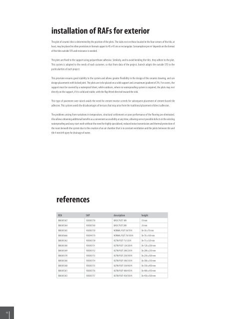
references<br />
KEA SAP description height<br />
B80305367 100083759 BASIC PLOT 10N 10 mm<br />
B80305364 100083760 BASIC PLOT 20N 20 mm<br />
B80305365 100083750 NORMAL PLOT 50/70 N De 50 a 70 mm<br />
B80305666 100094770 NORMAL PLOT 70/100 N De 70 a 100 mm<br />
B80305362 100083758 ULTRA PLOT 75/120 N De 75 a 120 mm<br />
B80305360 100083751 ULTRA PLOT 120/200 N De 120 a 200 mm<br />
B80305369 100083752 ULTRA PLOT 200/250 N De 200 a 250 mm<br />
B80305370 100083753 ULTRA PLOT 250/300 N De 250 a 300 mm<br />
B80305366 100083754 ULTRA PLOT 300/350 N De 300 a 350 mm<br />
B80305368 100083755 ULTRA PLOT 350/400 N De 350 a 400 mm<br />
B80305361 100083756 ULTRA PLOT 400/450 N De 400 a 450 mm<br />
B80305363 100083757 ULTRA PLOT 450/500 N De 450 a 500 mm<br />
44 45