

Morley Fire Panels Installation Manual - Smiths Technical Systems
Morley Fire Panels Installation Manual - Smiths Technical Systems
Morley Fire Panels Installation Manual - Smiths Technical Systems

You also want an ePaper? Increase the reach of your titles
YUMPU automatically turns print PDFs into web optimized ePapers that Google loves.
ZX <strong>Fire</strong> Alarm Control <strong>Panels</strong> MORLEY-IAS<br />
3.5.2 Loop Driver Cards<br />
• Adding loop driver cards to the base unit expands the system. There are expansion slots for one<br />
loop driver card in the ZX1Se, up to two loop driver cards in ZX2Se (designated Loop 1 and Loop<br />
2) and up to five loop drivers in ZX5Se (designated Loop 1 to Loop 5). The ZX10Se can be fitted<br />
with up to ten loop drivers – up to five per ZX5Se panel.<br />
• Note that the first loop, designated ‘loop 1’ is situated at the top right-hand side of the base card.<br />
• Each card is secured with the four M3x6 screws supplied.<br />
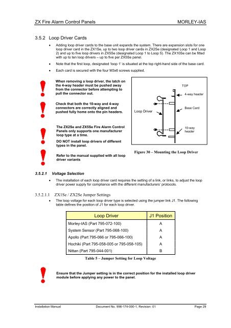
When removing a loop driver, the latch on<br />
the 4-way header must be pushed away<br />
from the connector before attempting to<br />
pull the connector out.<br />
Check that both the 10-way and 4-way<br />
connectors are correctly aligned and<br />
pushed fully home onto the pin headers.<br />
The ZX2Se and ZX5Se <strong>Fire</strong> Alarm Control<br />
<strong>Panels</strong> only supports one manufacturer<br />
loop type at a time.<br />
DO NOT install loop drivers of different<br />
types in the panel.<br />
Refer to the manual supplied with all loop<br />
driver variants<br />
3.5.2.1 Voltage Selection<br />
Loop Driver<br />
Base Card<br />
<strong>Installation</strong> <strong>Manual</strong> Document No. 996-174-000-1, Revision: 01 Page 29<br />
TOP<br />
4-way header<br />
10-way<br />
header<br />
Figure 30 – Mounting the Loop Driver<br />
• The installation of each loop driver card requires the setting of a link, or links, to adjust the loop<br />
driver power supply for compliance with the different manufacturers’ protocols.<br />
3.5.2.1.1 ZX1Se / ZX2Se Jumper Settings<br />
• The loop voltage for each loop driver type is selected using the jumper link J1. The following<br />
table defines the position of J1 for each loop driver.<br />
Loop Driver J1 Position<br />
<strong>Morley</strong>-IAS (Part 795-072-100) A<br />
System Sensor (Part 795-068-100) A<br />
Apollo (Part 795-066 or 795-066-100) A<br />
Hochiki (Part 795-058-005 or 795-058-105) A<br />
Nittan (Part 795-044-001) B<br />
Table 5 – Jumper Setting for Loop Voltage<br />
Ensure that the Jumper setting is in the correct position for the installed loop driver<br />
module before applying any power to the panel.


