

Morley Fire Panels Installation Manual - Smiths Technical Systems
Morley Fire Panels Installation Manual - Smiths Technical Systems
Morley Fire Panels Installation Manual - Smiths Technical Systems

You also want an ePaper? Increase the reach of your titles
YUMPU automatically turns print PDFs into web optimized ePapers that Google loves.
ZX <strong>Fire</strong> Alarm Control <strong>Panels</strong> MORLEY-IAS<br />
3.4.9 RS485 Wiring Arrangements<br />
EN54<br />
!<br />
EN54-2 12.5<br />
Integrity of<br />
transmission paths:<br />
The network does<br />
not provide the<br />
required<br />
transmission path<br />
integrity.<br />
3.4.9.1 Daisy Chain Style <strong>Installation</strong><br />
• Form the peripheral or<br />
panel RS485 link by taking<br />
wires from the A and B<br />
terminals at one side of<br />
the interface board<br />
connector to the A and B<br />
terminals of the next<br />
device on the link.<br />
• Continue wiring to all the<br />
units to be connected to<br />
the link – connecting A to<br />
A and B to B.<br />
• Install EOL (150R, 0.5W<br />
minimum, P/N 170-073-<br />
151) resistors in the spare<br />
terminals in both the first<br />
and last units on the link.<br />
• The maximum allowed<br />
length of the link is 1.2km<br />
(4000’).<br />
3.4.9.2 Loop Style <strong>Installation</strong><br />
• Form the peripheral or panel<br />
RS485 link by taking wires<br />
from the A and B terminals at<br />
one side of the interface board<br />
connector to the A and B<br />
terminals of the next device on<br />
the link.<br />
• Continue wiring to all the units<br />
to be connected to the link –<br />
connecting A to A and B to B.<br />
• Install return wiring from the<br />
spare terminals on the last unit<br />
to the spare terminals on the<br />
first unit.<br />
• The maximum allowed length<br />
of the complete loop is 1.2km<br />
(4000’).<br />
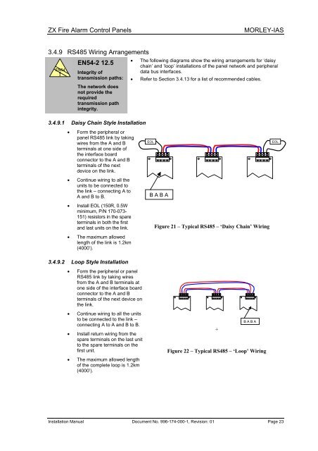
• The following diagrams show the wiring arrangements for ‘daisy<br />
chain’ and ‘loop’ installations of the panel network and peripheral<br />
data bus interfaces.<br />
• Refer to Section 3.4.13 for a list of recommended cables.<br />
EOL EOL<br />
B A B A<br />
Figure 21 – Typical RS485 – ‘Daisy Chain’ Wiring<br />
B A B A<br />
<strong>Installation</strong> <strong>Manual</strong> Document No. 996-174-000-1, Revision: 01 Page 23<br />
+<br />
Figure 22 – Typical RS485 – ‘Loop’ Wiring


