

Morley Fire Panels Installation Manual - Smiths Technical Systems
Morley Fire Panels Installation Manual - Smiths Technical Systems
Morley Fire Panels Installation Manual - Smiths Technical Systems

Create successful ePaper yourself
Turn your PDF publications into a flip-book with our unique Google optimized e-Paper software.
ZX <strong>Fire</strong> Alarm Control <strong>Panels</strong> MORLEY-IAS<br />
3.4 External Connections<br />
BEFORE INSTALLATION: Refer to Ratings / Type label located on the inside of the panel.<br />
3.4.1 Mains Power Input<br />
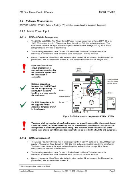
3.4.1.1 ZX1Se / ZX2Se Arrangement<br />
• The ZX1Se and ZX2Se <strong>Fire</strong> Alarm Control <strong>Panels</strong> receive power from either a 230V, 50Hz (or<br />
120V, 60Hz-power supply 1 ). The current flows through an EMI filter to the transformer. The<br />
transformer converts the input mains voltage to a safe extra-low voltage (SELV). All of these<br />
components are mounted to the chassis.<br />
• The incoming power feed cable Ground or Earth (Green or Green/Yellow) wire must be<br />
connected to the terminal block protective earth connection – middle terminal.<br />
• Connect the neutral (Blue/Black) wire to the terminal marked ‘N’ and connect the Phase or Live<br />
(Brown/Red) wire to the terminal marked ‘L’. The terminal block contains an integral fuse.<br />
Open and lock out the<br />
circuit breaker before<br />
connecting any wiring. Do<br />
not power the system until<br />
the installation is<br />
complete.<br />
Maintain separation<br />
between the 120/230V and<br />
the low voltage wiring. Do<br />
not route in the same<br />
trunking and keep apart in<br />
the enclosure.<br />
For EMC Compliance, fit<br />
the supplied Ferrite<br />
Absorber (large) as shown<br />
in the diagram.<br />
Blue<br />
Green/Yellow<br />
Brown<br />
Ferrite<br />
Large<br />
<strong>Installation</strong> <strong>Manual</strong> Document No. 996-174-000-1, Revision: 01 Page 9<br />
COM N/C N/O<br />
RELAY 2<br />
RELAY 2<br />
ISOLATE<br />
ELSEWHERE<br />
N<br />
L<br />
F1 T 2A H 250V<br />
Affix cable tie<br />
around wires<br />
below ferrite<br />
Fuse<br />
ISOLATE<br />
ELSEWHERE<br />
N<br />
Figure 5 – Mains Input Arrangement – ZX1Se / ZX2Se<br />
The panel shall be supplied with AC mains power via a readily-accessible, disconnect device<br />
(‘isolation’ switch) to facilitate servicing and be provided with suitable earth fault protection<br />
incorporated in the building installation wiring. The minimum cross-sectional area of the<br />
mains cable should be 0.75mm and the supply should be fused with a 5A HRC anti-surge fuse.<br />
3.4.1.2 ZX5Se Arrangement<br />
• The ZX5Se <strong>Fire</strong> Alarm Control Panel receives power from a 230V, 50Hz (or a 120V, 60Hz power<br />
supply 1 ). The current flows through an EMI filter and a chassis mounted fuse, to the transformer.<br />
The transformer converts the input mains voltage to a safe extra low voltage. All of these<br />
components are mounted to the chassis.<br />
• The incoming power feed cable Ground or Earth (Green or Green/Yellow) wire must be<br />
connected to the terminal block protective earth connection – middle terminal.<br />
• Connect the neutral (Blue/Black) wire to the terminal marked ‘N’ and connect the Phase or Live<br />
(Brown/Red) wire to the terminal marked ‘L’.<br />
1 With the appropriate transformer fitted.<br />
L


