Schoonbaert volledig - ie-net
Schoonbaert volledig - ie-net
Schoonbaert volledig - ie-net

You also want an ePaper? Increase the reach of your titles
YUMPU automatically turns print PDFs into web optimized ePapers that Google loves.
kvivFSE sp2inl1<br />
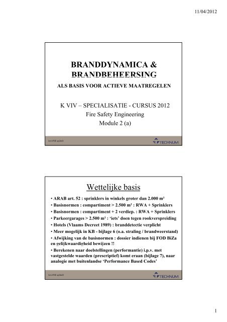
BRANDDYNAMICA &<br />
BRANDBEHEERSING<br />
ALS BASIS VOOR ACTIEVE MAATREGELEN<br />
K VIV – SPECIALISATIE - CURSUS 2012<br />
Fire Safety Engineering<br />
Module 2 (a)<br />
Wettelijke basis<br />
• ARAB art. 52 : sprinklers in winkels groter dan 2.000 m²<br />
• Basisnormen : compartiment > 2.500 m² : RWA + Sprinklers<br />
• BBasisnormen i : compartiment ti t + 2 verd<strong>ie</strong>p. di : RWA + Sprinklers S i kl<br />
• Parkeergarages > 2.500 m² : ‘<strong>ie</strong>ts’ doen tegen rookverspreiding<br />
• Hotels (Vlaams Decreet 1989) : branddetect<strong>ie</strong> verplicht<br />
• Meer mogelijk in KB - bijlage 6 (o.a. straling / brandweerstand)<br />
• Afwijking van de basisnormen : doss<strong>ie</strong>r ind<strong>ie</strong>nen bij FOD BiZa<br />
en gelijkwaardigheid g j g bewijzen j !!<br />
• Berekenen naar doelstellingen (performant<strong>ie</strong>) i.p.v. met<br />
vastgestelde waarden (prescript<strong>ie</strong>f) komt eraan (bijlage 7), naar<br />
analog<strong>ie</strong> met buitenlandse ‘Performance Based Codes’<br />
kvivFSE sp2inl2<br />
11/04/2012<br />
1
Gelijkwaardigheid =<br />
FSE in 3 stappen<br />
1. Kwalitat<strong>ie</strong>ve<br />
beoordeling (QDR)<br />
2. Kwantitat<strong>ie</strong>ve<br />
analyse<br />
3. Rapportering van<br />
de conclus<strong>ie</strong>s<br />
kvivFSE sp2inl3<br />
1. Kwalitat<strong>ie</strong>ve beoordeling<br />
• Vastleggen van doelstellingen en criteria<br />
• Beschrijving van het architecturale ontwerp<br />
• Vastleggen van gebouw-, gebruikers- en<br />
omgevingskarakterist<strong>ie</strong>ken<br />
• Identificat<strong>ie</strong> van de mogelijke brandrisico’s<br />
• Vastleggen van de relevante brandscenario’s<br />
• Beschrijving van de beveiligingsconcepten<br />
kvivFSE sp2inl4<br />
11/04/2012<br />
2
2. Kwantitat<strong>ie</strong>ve Analyse<br />
• Uitvoeren van berekeningen via gekende<br />
rekenmodellen<br />
• Resultaten vergelijken met de geëiste criteria<br />
• Eventueel concept aanpassen<br />
• Resultaat van de ene berekening (submodule)<br />
is de input van een volgende<br />
• Alles berekenen tot een goed resultaat<br />
kvivFSE sp2inl5<br />
3. Rapportering<br />
SUB - MODULES (BS 7974 – ISO 13387)<br />
1. Initiat<strong>ie</strong> en ontwikkeling van de brand in de<br />
aanvangsruimte *<br />
2. Verspreiding van rook * en toxische gassen<br />
3. Uitbraak van de brand * en structurele weerstand<br />
4. Detect<strong>ie</strong>, activat<strong>ie</strong> van bestrijdingsmiddelen *<br />
5. Intervent<strong>ie</strong> van de brandweer<br />
66. MMenselijke lijk factoren f t *<br />
7. Bevestiging van de risico-waarschijnlijkheid<br />
(* : wordt behandeld in deze lezing over branddynamica & brandbeheersing)<br />
kvivFSE sp2inl6<br />
11/04/2012<br />
3
Vuur Structuur Brandweer<br />
QDR Rook Det/Blus Evacuat<strong>ie</strong><br />
kvivFSE sp2inl7<br />
1 2 3 4 5 6 Subsystems<br />
Enkele theoretische begrippen<br />
• Brandlast / calorisch potentiaal / verbrandingswaarde<br />
van een brandbaar product = brandstof (kJ/kg of MJ/kg)<br />
– Naaldhout = 18 MJ/kg (m)ethanol = (20)-27 (20) 27 MJ/kg<br />
– Plastics = 25-40 MJ/kg ol<strong>ie</strong>producten en aardgas ≈ 45 MJ/kg<br />
• Verbranding : Brandstof + O 2 restproducten + Hitte + H 2O<br />
• Hitte verspreidt zich op 3 man<strong>ie</strong>ren :<br />
– 5 % Conduct<strong>ie</strong> of geleiding (warmte aan omgevende wanden)<br />
– 75 % Convect<strong>ie</strong> of verplaatsing (met rook als visueel element)<br />
– 20 % Radiat<strong>ie</strong> of straling door een ijl medium (zon / kampvuur)<br />
• Calorisch vermogen of total Heat Release Rate (HRR) :<br />
‘waarneembare’ vrijgekomen hitte = verbranding per<br />
tijdseenheid (kJ/s = kW of MJ/s = MW)<br />
kvivFSE sp2inl8<br />
11/04/2012<br />
4
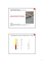
• Specif<strong>ie</strong>ke brandlast : calorisch potentiaal per oppervlakteeenheid<br />
(kJ/m² of MJ/m²); wordt bepaald door de hoeveelheid<br />
van brandgevaarlijk materiaal in een ruimte.<br />
criterium voor indeling naar categoriën bij allerlei<br />
normen (bv sprinkler-berekening)<br />
• Specif<strong>ie</strong>k vermogen of specific Heat Release Rate : te<br />
verwachten vrijgekomen hitte per oppervlakte-eenheid (kW/m²),<br />
toe te passen in berekeningen voor typische omgevingen :<br />
– Bureel = 130-290 kW/m² winkelshops = 500-750 kW/m²<br />
– Hotelkamer = 250 kW/m² Opslagruimte = 1500 – 3000 kW/m²<br />
• Verbrandingssnelheid : afname van het gewicht aan<br />
brandstof door verbranding (kg/s) hoe hoger deze snelheid,<br />
hoe meer vrijgekomen energ<strong>ie</strong> voor dezelfde brandlast !! Deze<br />
snelheid is n<strong>ie</strong>t constant vermogensp<strong>ie</strong>k<br />
• Rookproduct<strong>ie</strong> : waarneembare reststoffen, welke ongeacht<br />
de densiteit worden bijgemengd met omgevingslucht (kg/s of<br />
ook m³/s = temperatuur gecorrigeerd)<br />
kvivFSE sp2inl9<br />
Nuttige publicat<strong>ie</strong>s<br />
• An Introduction to Fire Dynamics (D. Drysdale – 1987/2001)<br />
• Fire Safety Design Guidelines for Federal Buildings (National<br />
Research Council of Canada – 1996)<br />
• BR 386 : Design Methodolog<strong>ie</strong>s for Smoke and Heat Ventilation<br />
Systems (BRE/Fire Research Station + Institution of Fire<br />
Engineers – UK - 1999)<br />
• The SFPE Handbook of Fire Protection Engineering 3th edition<br />
(Soc<strong>ie</strong>ty of Fire Protection Engineers – USA – 2002)<br />
• The NFPA Fire Protection Handbook 19th edition (National Fire<br />
Protection Association – USA -2003) + NFPA Standards (= normen)<br />
• CIBSE Guide E “Fire Fire Engineering” Engineering (Chartered Institution of<br />
Building Services Engineers – UK – 2003)<br />
• BS 5588 parts 1-11 : Fire Precautions in the design, construction<br />
and use of buildings (British Standards Institute – UK)<br />
• Europese en Belgische Normen + ANPI- publicat<strong>ie</strong>s + …..<br />
kvivFSE sp2inl10<br />
11/04/2012<br />
5
kvivFSE4 sp2tsq1<br />
kvivFSE sp2tsq2<br />
T – SQUARED FIRE GROWTH<br />
EEN REALISTISCHE KEUZE<br />
K VIV – SPECIALISATIE - CURSUS 2012<br />
Fire Safety Engineering<br />
Module 2 (b)<br />
react<strong>ie</strong> bij brand<br />
act<strong>ie</strong>ve elementen<br />
Brandverloop<br />
weerstand tegen brand<br />
pass<strong>ie</strong>ve elementen<br />
1
kvivFSE sp2tsq3<br />
Volontwikkeld na Flashover<br />
Groeifase voor Flashover<br />
• Overgang van initiat<strong>ie</strong>fase<br />
(incubat<strong>ie</strong> op laag niveau)<br />
naar groeifase if<br />
• Afhankelijk van type<br />
brandstof en ventilat<strong>ie</strong><br />
• Vastleggen van een virtueel ontstekingspunt to • Groeikromme (x², x³, exponent<strong>ie</strong>el)<br />
• Continu groe<strong>ie</strong>nd naar Flashover, brandstofbepaald<br />
of gestopt door blussing<br />
kvivFSE sp2tsq4<br />
2
Keuze voor kwadratische groeicurve<br />
• Experimentele gegevens (1972 : FM, NIST, FRS)<br />
• Eerst 3 curves c r es : Slow, Slo Medium Medi m en Fast<br />
• Daarna nog een curve Ultra-fast<br />
• Tijdsconstante tg (sec) : tot 1.000 btu/sec<br />
600sec (S) ( ) – 300sec (M) ( ) – 150sec (F) ( ) – 75sec (UF) ( )<br />
kvivFSE sp2tsq5<br />
kvivFSE sp2tsq6<br />
Q = 1.000 (t/tg)² (btu/sec)<br />
NFPA 92B (appendix C)<br />
3
kvivFSE sp2tsq7<br />
kvivFSE sp2tsq8<br />
Q = a t² (kW)<br />
met a = 1.055/(tg ( g )² ) (1 ( btu/sec = 1.055 W) )<br />
Slow : a = 1.055/(600)² = 0,0029<br />
Medium : a = 1.055/(300)² = 0,012<br />
Fast : a = 10 1.055/(150)² /(10)² = 004 0,047<br />
Ultra-fast : a = 1.055/(75)² = 0,188<br />
Q = a .t² (kW)<br />
1,000<br />
750<br />
500<br />
250<br />
0<br />
a = 0,0029 (600 s)<br />
SLOW<br />
t (s)<br />
0 60 120 180 240 300 360 420 480 540 600<br />
4
kvivFSE sp2tsq9<br />
Q = a .t² (kW)<br />
4,000<br />
3,500<br />
3,000<br />
2,500<br />
2,000<br />
1,500<br />
1,000<br />
500<br />
0<br />
a = 0,012 (300 s)<br />
a = 0,0029 (600 s)<br />
MEDIUM<br />
t (s)<br />
0 60 120 180 240 300 360 420 480 540 600<br />
Q = a .t² (kW)<br />
10,000<br />
9,000<br />
8,000<br />
7,000<br />
6,000<br />
5,000<br />
4,000<br />
3,000<br />
2,000 ,<br />
1,000<br />
0<br />
kvivFSE sp2tsq10<br />
a = 0,047 (150 s)<br />
a = 0,012 (300 s)<br />
a = 0,0029 (600 s)<br />
FAST<br />
0 60 120 180 240 300 360 420 480 540<br />
t (s)<br />
600<br />
5
Q = a .t² (kW)<br />
20,000<br />
18,000<br />
16,000 a = 0,188 (75 s)<br />
14,000<br />
12,000<br />
10,000<br />
8,000<br />
6,000<br />
4000 4,000<br />
2,000<br />
0<br />
kvivFSE4 sptsq11<br />
kvivFSE sp2tsq12<br />
a = 0,047 (150 s)<br />
a = 0,012 (300 s)<br />
a = 0,0029 (600 s)<br />
ULTRA - FAST<br />
0 60 120 180 240 300 360 420 480 540<br />
t (s)<br />
600<br />
Keuze van groeiparameter a<br />
Woning of bureel : Medium<br />
Winkelruimte (shop) : Fast<br />
St Stockageruimte k i t : Ult Ultra-fast f t<br />
Hotelkamer : Medium<br />
Grote zaal (toneel, confer. ,...) : Fast - Medium<br />
Klass<strong>ie</strong>k museum : Slow<br />
Act<strong>ie</strong>f museum : Medium<br />
Exposit<strong>ie</strong>ruimte (Fl. Expo) : Fast<br />
Vluchtige brandstoffen (benzine, alcohol) : U-F<br />
.... : met overleg te bepalen<br />
6
kvivFSE sp2tsq13<br />
Internationale groeicurves<br />
Fire And Smoke Transport – model (NIST)<br />
kvivFSE sp2tsq14<br />
7
Andere factoren<br />
• Pré-flashover te berekenen in eenzelfde ruimte<br />
(sprinkleractivat<strong>ie</strong> of RWA in een grote hall)<br />
•Post-flashover fl h levert l data d voor een aanliggend li d<br />
compartiment (RWA in een atrium)<br />
• P<strong>ie</strong>kvermogen ± 200 % (brandlast / brandduur)<br />
(100 kg hout op 20 min = 1.800 MJ / 1.200 s x 200% = 3.000 kW)<br />
• Rekstapeling in stapelmagazijnen : Q = 0,045 t³<br />
• Straling en terugstraling speelt een belangrijke<br />
rol ter bepaling van de flashover<br />
kvivFSE sp2tsq15<br />
8
kvivFSE sp2cjt1<br />
kvivFSE sp2cjt2<br />
DE ‘CEILING JET’<br />
DE MOTOR TOT FLASHOVER<br />
K VIV – SPECIALISATIE - CURSUS 2012<br />
Fire Safety Engineering<br />
Module 2 (c)<br />
Ceiling Jet – Principe (1955)<br />
• Warme lucht (rook) stijgt<br />
• Botst tegen plafond<br />
• Verspreidt zich egaal in<br />
de 4 richtingen<br />
• Snelheid = f (Q,H,r)<br />
• TTemperatuur t = f (Q,H,r) (QH )<br />
• Direct boven de brand<br />
speelt de straal (r)geen rol<br />
1
kvivFSE sp2cjt3<br />
Basisformules vaste vuurhaard<br />
Temperatuur (°C) :<br />
16,<br />
9⋅<br />
Q<br />
voor r/H O 0,18 : ΔT<br />
= 5/<br />
3<br />
H<br />
snelheid<br />
(m/s)<br />
tempe eratuur (°C x 100)<br />
kvivFSE sp2cjt4<br />
voor r/H > 0,18 :<br />
Snelheid (m/s) :<br />
15.00<br />
14.00<br />
13.00<br />
12.00<br />
11.00<br />
10.00<br />
voor r/H O 0,15 , :<br />
900 9.00<br />
8.00<br />
7.00<br />
6.00<br />
5.00<br />
4.00<br />
3.00<br />
2.00<br />
1.00<br />
voor r/H > 0,15 :<br />
2 / 3<br />
5, 38⋅<br />
( Q / r)<br />
ΔT<br />
=<br />
H<br />
U g<br />
U g<br />
2/<br />
3<br />
= 0, 96⋅<br />
( (QQ<br />
/ H )<br />
=<br />
0,<br />
195<br />
⋅Q<br />
r<br />
1/<br />
3<br />
5/<br />
6<br />
Ceiling Jet waarden voor H = 3m<br />
1/<br />
3<br />
⋅ H<br />
1/<br />
2<br />
0.00<br />
0 0.5 1 1.5 2 3 4 6 8<br />
Straal r (m)<br />
10<br />
snelheid met Q = 10,000 kW temperatuur met Q = 10,000 kW<br />
snelheid met Q = 5,000 kW temperatuur met Q = 5,000 kW<br />
snelheid met Q = 2,000 kW temperatuur met Q = 2,000 kW<br />
snelheid met Q = 1,000 kW temperatuur met Q = 1,000 kW<br />
snelheid met Q = 500 kW temperatuur met Q = 500 kW<br />
2
snelheid<br />
(m/s)<br />
tempe eratuur (°C x 100)<br />
kvivFSE sp2cjt5<br />
snelheid<br />
(m/s)<br />
tempe eratuur (°C x 100)<br />
kvivFSE sp2cjt6<br />
13.00<br />
12.00<br />
11.00<br />
10.00<br />
9.00<br />
8.00<br />
7.00<br />
6.00<br />
5.00<br />
4.00<br />
3.00<br />
2.00<br />
1.00<br />
Ceiling Jet waarden voor H = 5m<br />
0.00<br />
0 0.5 1 1.5 2 3 4 6 8<br />
Straal r (m)<br />
10<br />
11.00<br />
10.00<br />
9.00<br />
8.00<br />
7.00<br />
6.00<br />
5.00<br />
4.00<br />
3.00<br />
2.00<br />
1.00<br />
snelheid met Q = 10,000 kW temperatuur met Q = 10,000 kW<br />
snelheid met Q = 5,000 kW temperatuur met Q = 5,000 kW<br />
snelheid met Q = 2,000 kW temperatuur met Q = 2,000 kW<br />
snelheid met Q = 1,000 kW temperatuur met Q = 1,000 kW<br />
snelheid met Q = 500 kW temperatuur met Q = 500 kW<br />
Ceiling Jet waarden voor H = 10 m<br />
0.00<br />
0 0.5 1 1.5 2 3 4 6 8<br />
Straal r (m)<br />
10<br />
snelheid met Q = 10,000 kW temperatuur met Q = 10,000 kW<br />
snelheid met Q = 5,000 kW temperatuur met Q = 5,000 kW<br />
snelheid met Q = 2,000 kW temperatuur met Q = 2,000 kW<br />
snelheid met Q = 1,000 kW temperatuur met Q = 1,000 kW<br />
snelheid met Q = 500 kW temperatuur met Q = 500 kW<br />
3
Met een T² groe<strong>ie</strong>nde vuurhaard<br />
1) Bepalen van een aantal tussenwaarden (dimens<strong>ie</strong>loos*) :<br />
• t f *=0,954 (1+( r t f 0,954 (1 ( / H)) H))<br />
• A = g / (To.ro) = 9,81 / (293 . 1,208) = 0,0278<br />
2) Bepalen van de fict<strong>ie</strong>ve DT en snelheid op tijdstip t:<br />
kvivFSE sp2cjt7<br />
−1/<br />
5 −1/<br />
5 4 / 5<br />
( A ⋅α<br />
⋅ H )<br />
r<br />
0,<br />
188 0,<br />
313⋅<br />
( / )<br />
⎛ t /<br />
− t<br />
ΔT*<br />
= ⎜<br />
⎜<br />
⎝ + H<br />
U* = 0,<br />
59 ⋅ H<br />
r −0,<br />
63<br />
( / ) ⋅ ΔT<br />
*<br />
f<br />
* ⎞<br />
⎟<br />
⎟<br />
⎠<br />
4 / 3<br />
(ind<strong>ie</strong>n negat<strong>ie</strong>f DT* = 0 )<br />
3) Bepalen Ceiling Jet temperatuur en snelheid<br />
Temperatuur (°C) :<br />
Snelheid (m/s) :<br />
2/<br />
5<br />
2/<br />
5 −3/<br />
5<br />
( A ( T / 9,<br />
81)<br />
⋅ H ) + ( T − 273)<br />
t = ΔT<br />
* ⋅<br />
α<br />
g<br />
o<br />
1/<br />
5 1/<br />
5 1/<br />
5<br />
( A ⋅ ⋅ H )<br />
U = U * ⋅ αα<br />
⋅ H<br />
U g<br />
Met a = 0,0029 (slow) / 0,012 (medium) / 0,047 (fast) / 0,188 (ultra-fast)<br />
kvivFSE sp2cjt8<br />
o<br />
4
kvivFSE sp2cjt9<br />
snelheid (mm/s)<br />
Temperatuur (° °C x 100)<br />
snelheid (mm/s)<br />
Temperatuur (°C C x 100)<br />
kvivFSE sp2cjt10<br />
5.00<br />
4.50<br />
4.00<br />
3.50<br />
300 3.00<br />
2.50<br />
2.00<br />
1.50<br />
1.00<br />
0.50<br />
0.00<br />
5,00<br />
4,50<br />
4,00<br />
3,50<br />
300 3,00<br />
2,50<br />
2,00<br />
1,50<br />
1,00<br />
0,50<br />
0,00<br />
Ceiling Jet T-squared met H = 3 m en r = 2 m<br />
0 20 40 60 80 100 120 140 160<br />
Tijdsverloop in seconden<br />
temperatuur (Ultra-fast) snelheid (Ultra-fast)<br />
temperatuur (Fast) snelheid (Fast)<br />
temperatuur (Medium) snelheid (medium)<br />
temperatuur (Slow) snelheid (Slow)<br />
Ceiling Jet T-squared met H = 10 m en r = 2 m<br />
0 20 40 60 80 100 120 140 160<br />
Tijdsverloop in seconden<br />
temperatuur (Ultra-fast) snelheid (Ultra-fast)<br />
temperatuur (Fast) snelheid (Fast)<br />
temperatuur (Medium) snelheid (medium)<br />
temperatuur (Slow) snelheid (Slow)<br />
5
FAST<br />
Belangrijk : plaats vd vuurhaard !<br />
kvivFSE sp2cjt11<br />
FAST<br />
Belangrijk : grootte van het compartiment !<br />
kvivFSE sp2cjt12<br />
6
kvivFSE sp2cjt13<br />
Bepalende factoren tot flashover<br />
1. Grootte van het compartiment, ofwel oppervlakte van de<br />
omgevende wanden At<br />
• Qloss(cond) = k1.At.Dtgas (kW)<br />
• Qloss(rad) = k2.s.At. (Tgas 4 -To 4 ) (kW)<br />
waarbij k2 = f (emissiviteit(e) en % aanstraling)<br />
en s = cte van Stefan-Bolzman = 5,67 x 10 -11 kW/m 2 K 4<br />
2. Grootte van de ventilat<strong>ie</strong>-openingen<br />
• Ao : oppervlakte van de openingen (m²)<br />
• Ho : (gemiddelde) hoogte van de openingen (m)<br />
ventilat<strong>ie</strong>factor : (m5/2 )<br />
A<br />
o o H<br />
Minimaal vermogen tot flashover<br />
Belangrijk onderzoek levert analoge bevindingen op :<br />
V. Babrauskas (1981) ( ) – P. Thomas (1981) ( ) – A. Heselden (1981) ( ) -<br />
J. Quint<strong>ie</strong>re (1981) – M. Law (1983) – D. Drysdale (1985)<br />
basisparameter : flashover treedt op bij DT ≅ 550°C<br />
Eenvoudige formule : Qfo = 750 . AoHo 1/2 (kW)<br />
i Q 78A + 378 A H 1/2<br />
Prec<strong>ie</strong>zer : Qfo = 7,8 At + 378 . AoHo 1/2<br />
met At = Afloor + Aceiling + Awalls –Ao (m²) en At > 10 AoHo 1/2<br />
kvivFSE sp2cjt14<br />
(kW)<br />
7
kvivFSE sp2cjt15<br />
Q = 20.000 kW<br />
Q = 18.100 kW<br />
Q = 16.300 kW<br />
Q = 14.600 kW<br />
Q = 13.000 kW<br />
Q = 11.500 kW<br />
Q = 10.100 kW<br />
Q = 8.800 8 800 kW<br />
Q = 7.600 kW<br />
Q = 6.500 kW<br />
Q = 5.500 kW<br />
Q = 4.600 kW<br />
Q = 3.800 kW<br />
Q = 3.100 kW<br />
Q = 2.500 kW<br />
Q = 2.000 kW<br />
Q = 1.600 kW<br />
Q = 1.300 kW<br />
Q = 1.000 kW<br />
graf<strong>ie</strong>kgrens<br />
Ventilat<strong>ie</strong>factor<br />
Ao(Ho)^1/2<br />
39<br />
36<br />
33<br />
30<br />
27<br />
24<br />
21<br />
18<br />
15<br />
12<br />
9<br />
6<br />
3<br />
0<br />
50<br />
60<br />
80<br />
110<br />
150<br />
Flashover Grenswaarden<br />
200<br />
Oppervlakte omsloten wanden At (m²)<br />
260<br />
330<br />
410<br />
500<br />
600<br />
710<br />
830<br />
960<br />
1.100<br />
1.260<br />
1.440<br />
Maximum temperatuur na flashover<br />
H<strong>ie</strong>rbij spelen zowel de compartimentsgrootte, de ventilat<strong>ie</strong>factor<br />
als de totale brandlast in het lokaal een rol :<br />
(t )+ΔT 6000 (1 e-0 10x (t ) -05 (1 e-0 05y<br />
o)+ΔT = 6000.(1 – e ) (°C)<br />
-0,10x ).x-0,5 .(1 – e-0,05y ) ( C)<br />
Met x = A t / (A oSH o )<br />
y = P / [18 S(A o .A t )]<br />
En P is de totale brandlast (MJ)<br />
P/18 = equivalent kg hout<br />
kvivFSE sp2cjt14<br />
1250<br />
1000<br />
750<br />
500<br />
250<br />
ruimte van 10 m x 5 m x 3 m (met 1 opening)<br />
5 m x 2 m 3 m x 2 m 3 m x 1 m<br />
max temp °C<br />
kg hout<br />
250 350 500 1.000 2.500 5.000 10.000<br />
8
RTI = FLASHOVER VERMIJDEN<br />
Rap en op Tijd voor Intervent<strong>ie</strong><br />
kvivFSE sp2rti1<br />
K VIV – SPECIALISATIE - CURSUS 2012<br />
Fire Safety Engineering<br />
Module 2 (d)<br />
Snelle intervent<strong>ie</strong> na snelle ontdekking<br />
• Reukzin van de aanwezigen<br />
• Permanente monstername van de lucht<br />
• Visuele waarneming van de vuurhaard<br />
• Opmerken van rook<br />
• Rook detecteren in n<strong>ie</strong>t bemande ruimtes<br />
• Aanvoelen van stralingswarmte<br />
• Meting van een temperatuursverhoging<br />
kvivFSE sp2rti2<br />
1
Automatisch reageren op temperatuur<br />
• Thermische detector met vaste waarde<br />
• Thermodifferent<strong>ie</strong>el detector<br />
• Lineaire detector (laserlicht-principe)<br />
• Tubulaire detector (drukverhogings-principe)<br />
• Smeltlood (sprinkler, rookluik, brandklep)<br />
• Glasbulb (sprinkler, rookluik) ( filmpje)<br />
kvivFSE sp2rti3<br />
kvivFSE sp2rti4<br />
Bepalende factoren voor werking<br />
van het detect<strong>ie</strong>-element :<br />
1. Activat<strong>ie</strong>-temperatuur :<br />
• Statische detectoren : 50 50°-58°-71°-92°<br />
58 71 92<br />
• Different<strong>ie</strong>eldetectoren : 5°/min - 8°/min – 14°/min<br />
• Smeltlood : 72° - 101°<br />
• Glasbulb : 57°(Or) – 68°(Ro) – 79°(Ge) – 93°(Gr) – 141° (Bl)<br />
2. Gevoeligheid (i.f.v.) :<br />
• Massiviteit van het geheel<br />
• Detect<strong>ie</strong>-oppervlakte<br />
• Soortelijke warmte van het materiaal<br />
• Warmte-overdracht<br />
2
Gevoeligheid = Response Time Index (RTI)<br />
kvivFSE sp2rti5<br />
kvivFSE sp2rti6<br />
I. De detect<strong>ie</strong> d<strong>ie</strong>nt te gebeuren tijdens de aanvangsfase<br />
van de brand : De convect<strong>ie</strong>ve warmte-overdracht is<br />
overheersend over straling en geleiding Q = Qconv Qconv<br />
q = qconv = h.A.(Tg –Td) (kW)<br />
• q = de fract<strong>ie</strong> van Q d<strong>ie</strong> het detect<strong>ie</strong>-element bereikt<br />
• h = de convect. warmte-overdrachts coëfficiënt (kW/m²K)<br />
• A = de werkzame oppervlakte van de detector (m²)<br />
•Tg = Temperatuur van de hete gassen (K)<br />
•Td = Temperatuur van het detect<strong>ie</strong>-element (K)<br />
II. Het element zal opwarmen in funct<strong>ie</strong> van<br />
de tijd en materiaal-eigenschappen<br />
dT dTd/dt /dt = q / (m.c) (m c) (°C/ (°C/s) )<br />
• q = de fract<strong>ie</strong> van Q d<strong>ie</strong> het detect<strong>ie</strong>-element bereikt<br />
• m = de effect<strong>ie</strong>ve massa van het element (kg)<br />
• c = de soortelijke j warmte van het element (kJ/kg.K) ( g )<br />
• dt = differentiële tijdstoename (s)<br />
•dTd = Temperatuurstoename van het element (K of °C)<br />
3
III. Voor elk detect<strong>ie</strong>-element kan men een tijdsconstante<br />
berekenen, onafhankelijk van de warmtestroom q :<br />
kvivFSE sp2rti7<br />
[ h.A.(Tg-Td) = m.c.(dTd/dt) ]<br />
dt ⋅(<br />
Tg<br />
−Td<br />
) m⋅<br />
c<br />
τ =<br />
=<br />
dT h ⋅ A<br />
d<br />
De warmte-overdrachtscoëfficiënt h is echter wél afhankelijk<br />
van de ‘Ceiling Jet snelheid’ (Ug) [ h = f( 1/Ug 1/2 ) ] zodat :<br />
RTI = t.Ug 1/2<br />
(s)<br />
(m 1/2 .s 1/2 ) (= cte)<br />
Deze Response Time Index is een vaste waarde en d<strong>ie</strong>nt<br />
opgegeven door de fabricant van het detect<strong>ie</strong>-element<br />
Typische RTI - waarden<br />
• Thermische detector : 30<br />
• Standaard sprinkler (bulb) : 135 - 350<br />
• Quick response sprinkler (bulb) : 50 - 80<br />
• Smeltlood : 25 (ESFR) - ??? (brandklep)<br />
• (Rookdetector : 0,5 0 5 en Tact. Tact = To To +15°) + 15 )<br />
• Volgens testen van UL (thermische detectoren ) :<br />
van 11 tot 495 (in funct<strong>ie</strong> van spreiding onder het plafond)<br />
kvivFSE sp2rti8<br />
4
kvivFSE sp2rti9<br />
Activat<strong>ie</strong>tijd van een detector<br />
1) Met vaste vuurhaard : Q = cte<br />
kvivFSE sp2rti10<br />
Gekende gegevens :<br />
QT Q, To, HH, rr, RTI RTI, TTactt (detector of sprinkler)<br />
Tg (K) en Ug (m/s)<br />
volgen uit de Ceiling Jet<br />
formules (z<strong>ie</strong> vorig Hfdk)<br />
⋅ ( T − T<br />
U ⋅ ( T − T )<br />
dt g d )<br />
Uit τ =<br />
volgt :<br />
dT<br />
d<br />
dT dTd g g d<br />
=<br />
dt<br />
RTI<br />
dTd / dt : temperatuursstijging v/d detector per tijdseenheid (K/s)<br />
Td : berekende detector-temperatuur (K)<br />
Het detect<strong>ie</strong>-element zal reageren (electrisch signaal of<br />
sprinklerkop opent zich) wanneer Td > Tact<br />
Td Td wordt opgelost volgens de vergelijking :<br />
T<br />
d , t + Δt<br />
= T<br />
d , t<br />
+<br />
( Tg<br />
− Td<br />
, t<br />
) ⋅ ( 1−<br />
e<br />
U g<br />
−<br />
RTI<br />
H<strong>ie</strong>rbij wordt geldt als eerste waarde voor Td = To en<br />
wordt met een tijdstap Dt van 1 sec. telkens een n<strong>ie</strong>uwe<br />
Td berekend totdat Tact wordt overschreden.<br />
)<br />
5
kvivFSE sp2rti11<br />
kvivFSE sp2rti12<br />
XLS - berekening<br />
Response time activat<strong>ie</strong> na 74 seconden<br />
Q 8000 kW<br />
To 20 °C = 293 K<br />
Tact 68 °C = 341 K<br />
H 6 m<br />
r 5 m<br />
RTI 230 m^(1/2).s^(1/2)<br />
Ug 25m/s 2,5 m/s<br />
Tg 416 K = 143 °C<br />
start 293 tijd (s)<br />
294 1<br />
295 2<br />
296 3<br />
296 4<br />
FAST (cte)<br />
6
2) Met vuurhaard : Q = a.t²<br />
In principe kan dezelfde redenering worden opgebouwd maar dan<br />
met een warmtevermogen Q dat verhoogt met <strong>ie</strong>dere tijdsstap.<br />
Zodoende zijn Tg en Ug n<strong>ie</strong>t constant en d<strong>ie</strong>nen deze telkens<br />
berekend zoals onder het hoofdstuk “ceiling jet”.<br />
De differentiaalvergelijk wordt dan ook opgelost met een<br />
bijkomende term :<br />
1<br />
−<br />
T Td , t + Δt<br />
= T Td<br />
, t<br />
Δ t<br />
ττ + ( T Tg<br />
, t + Δt<br />
− T Td<br />
, t ) ⋅ ( 1 1−<br />
e ) + ( T Tg<br />
, t + t − T Tg<br />
, ) ⋅τ<br />
⋅ ( e<br />
Waarbij t = RTI /Ug 1/2 en veranderlijk in de tijd<br />
Ook Tg start met de waarde To en wordt per seconde berekend<br />
kvivFSE sp2rti13<br />
Response time activat<strong>ie</strong> na 246 seconden<br />
bij 2844 kW<br />
a 0,047 kW/s²<br />
To 20 °C = 293 K<br />
Tact 68 °C = 341 K<br />
H 6 m<br />
r 5 m<br />
RTI 80 m^(1/2).s^(1/2)<br />
XLS - berekening<br />
1<br />
−<br />
ττ<br />
1<br />
+ − 1 )<br />
τ<br />
r/H 0,833 -<br />
tf* 1,75 s<br />
A 0,0278<br />
Tg Td<br />
start Q t2* DT* U* 293 Ug t 293,0 tijd (s)<br />
1 0 0,1 0,0 0,0 293 0,0 400,0 293,0 1<br />
2 0 0,1 0,0 0,0 293 0,0 400,0 293,0 2<br />
3 0 0,2 0,0 0,0 293 0,0 400,0 293,0 3<br />
4 1 0,3 0,0 0,0 293 0,0 400,0 293,0 4<br />
5 1 0,3 0,0 0,0 293 0,0 400,0 293,0 5<br />
6 2 0,4 0,0 0,0 293 0,0 400,0 293,0 6<br />
7<br />
kvivFSE sp2rti14<br />
8<br />
2<br />
3<br />
0,4<br />
0,5<br />
0,0<br />
0,0<br />
0,0<br />
0,0<br />
293<br />
293<br />
0,0<br />
0,0<br />
400,0<br />
400,0<br />
293,0<br />
293,0<br />
7<br />
8<br />
9 4 06 00 00 293 00 400 0 293 0 9<br />
7
kvivFSE sp2rti15<br />
FAST (Tsq)<br />
8
BLUSSING DOOR SPRINKLERS<br />
Is de bluswatercapaciteit echt nodig<br />
kvivFSE sp2spr1<br />
K VIV – SPECIALISATIE - CURSUS 2012<br />
Fire Safety Engineering<br />
Module 2 (e)<br />
Installat<strong>ie</strong> volgens de ‘norm’<br />
• NBN S21-028, CEA 4001, EN 12845, NFPA 13, FMglobal,...<br />
• Conservat<strong>ie</strong>ve benadering = “worst case scenario”<br />
• Potent<strong>ie</strong>el gevaar brandklasse deb<strong>ie</strong>t (densiteit x<br />
werkzame oppervlakte Buffercapaciteit (i.f.v.<br />
gevraagde werkduur)<br />
• Maximale druk aan laatste sprinkler<br />
• Bepalen l van pompkarakterist<strong>ie</strong>k k k i i k(i (i.f.v. f leiding l idi lay-out) l )<br />
• Electrisch- en/of D<strong>ie</strong>sel-vermogen<br />
• Installat<strong>ie</strong>, rekening houdend met structuur / obstakels<br />
kvivFSE sp2spr2<br />
1
Mogelijke optimalisat<strong>ie</strong><br />
1) Is het vereiste waterdeb<strong>ie</strong>t een vast gegeven ?<br />
kvivFSE sp2spr3<br />
NFPA 13 : 6,1 x 372 = 2x (8,1 x 139) !!<br />
2) Gebruik van het type sprinkler i.f.v. de parameters :<br />
opstelling / sproeicurve / snelheid / grootte(K-factor)<br />
Standard spray (pendent – upright)<br />
kvivFSE sp2spr4<br />
Flush spray (recessed)<br />
Sidewall<br />
Concealed Ceiling<br />
Extended Coverage<br />
EExtra t Large L Orifice O ifi<br />
Early Suppression Fast Response (stapeling)<br />
Large Drop<br />
2
kvivFSE sp2spr5<br />
kvivFSE sp2spr6<br />
Quick Response Sprinkler (L & OH)<br />
NFPA 13<br />
Verminderde werkzame<br />
oppervlakte bij gebruik van<br />
Quick Response Sprinklers* !<br />
H > 6 m : - 0 %<br />
H < 3 m : - 40 %<br />
3 m [ H [ 6 m : (5 (5.H–55) H 55) %<br />
* Toepasbaar in kantoorgebouwen en (grote) winkelruimtes<br />
3) Wat is de werkelijke blussingskracht<br />
Uit deb<strong>ie</strong>t en druk ( Q = K . P 1/2 ) en het toegepaste<br />
sprinkler-type volgt :<br />
• Druppelgrootte (diameter dm of oppervlakte Ad)<br />
Ad y Q / dm y Q.P1/3 / Ø 2/3<br />
[ toepassing = watermist (120 bar) : 1 L / 6 m³ lokaal ]<br />
• PPe<strong>net</strong>rat<strong>ie</strong> i = f ( (snelheid lh id en grootte) )<br />
• Hoeveelheid \<br />
• Spreiding / Densiteit (L / min.m²) of mw (mm/s)<br />
3
NFPA handbook<br />
kvivFSE sp2spr7<br />
kvivFSE sp2spr8<br />
Een minimale densiteit is<br />
vereist i.f.v. de brandlast,<br />
anders is blussing onmogelijk :<br />
Bepaling van de blussingscurve (reëel) - 1993<br />
Q t −<br />
= Q<br />
( t act ) t act<br />
⋅ e<br />
⎛<br />
⎜<br />
( t − t<br />
⎜<br />
⎝ 3⋅(<br />
m w )<br />
act<br />
− −1<br />
, 85<br />
tact : tijdstip waarop de sprinkler wordt geactiveerd (s)<br />
mw : waterdensiteit van de sprinkler (mm/s)<br />
)<br />
⎞<br />
⎟<br />
⎠<br />
4
TEST : Blussing bij 0,07 mm/s (4,2 L/min.m²) noemer = 410<br />
kvivFSE sp2spr9<br />
Medium / Qact = 2500 kW<br />
Vermogen (kkW)<br />
4000<br />
3000<br />
2000<br />
1000<br />
0<br />
BLUSTIJD = f (densiteit)<br />
0<br />
80<br />
160<br />
240<br />
320<br />
400<br />
480<br />
560<br />
640<br />
720<br />
800<br />
880<br />
960<br />
1040<br />
1120<br />
1200<br />
1280<br />
1360<br />
1440<br />
1520<br />
1600<br />
1680<br />
1760<br />
kvivFSE sp2spr10<br />
tijd (s)<br />
densiteit = 2 L/min.m² densiteit = 3 L/min.m² densiteit = 4 L/min.m² densiteit = 5 L/min.m²<br />
densiteit = 6 L/min.m² densiteit = 7 L/min.m² densiteit = 8 L/min.m² densiteit = 9 L/min.m²<br />
5
U-fast / Qact = 7500 kW<br />
Vermogen (kkW)<br />
kvivFSE sp2spr11<br />
10000<br />
9000<br />
8000<br />
7000<br />
6000<br />
5000<br />
4000<br />
3000<br />
2000<br />
1000<br />
0<br />
0<br />
90<br />
BLUSTIJD = f (densiteit)<br />
180<br />
270<br />
360<br />
450<br />
540<br />
630<br />
720<br />
810<br />
900<br />
990<br />
1080<br />
1170<br />
1260<br />
1350<br />
1440<br />
1530<br />
1620<br />
1710<br />
1800<br />
tijd (s)<br />
densiteit = 2 L/min.m² densiteit = 4 L/min.m² densiteit = 6 L/min.m² densiteit = 8 L/min.m²<br />
densiteit = 10 L/min.m² densiteit = 12 L/min.m² densiteit = 14 L/min.m² densiteit = 16 L/min.m²<br />
4) Finale berekening<br />
• Vastleggen van het vuurhaard-type en Tsq – curve<br />
• Keuze van type sprinklers (RTI)<br />
• Keuze van druk/deb<strong>ie</strong>t parameters (K-factor)<br />
• Activat<strong>ie</strong>tijd bepalen (ceiling jet !) en nakijken hoeveel sprinklers<br />
afgaan : blussing / controle<br />
• Blussingstijd berekenen<br />
• Benodigde watervoorraad (m (m³) ) :<br />
blustijd x aantal sprinklers x sprinklerdeb<strong>ie</strong>t<br />
• Let wel : Dit is een praktische FSE – benadering, géén norm !!<br />
kvivFSE sp2spr12<br />
6
kvivFSE sp2rad1<br />
kvivFSE sp2rad2<br />
STRALING & VLAMMEN<br />
Als de brand dan toch uitbreidt<br />
KVIV– K VIV SPECIALISATIE - CURSUS 2012<br />
Fire Safety Engineering<br />
Module 2 (f)<br />
Straling vanuit een open vlam<br />
• Gelijkmatig verdeeld over een halve bol<br />
• Omgekeerd evenredig tot de afstand ² (R)<br />
• Lineair afhankelijk van het warmtevermogen (Q)<br />
• Afhankelijk van de diameter van de vuurhaard (D)<br />
• Rekening houden met het stralingsaandeel (cr)<br />
χr<br />
⋅Q<br />
q =<br />
4π ⋅ R²<br />
[ cr = 0,21 – 0,0034.D y 20 % in open lucht ]<br />
(kW/m²)<br />
1
40 kW/m² :<br />
Zware<br />
structuren<br />
20 kW/ kW/m² ² :<br />
Lichte<br />
structuren<br />
15 kW/m² :<br />
VVeilige ili afstand f t d<br />
1,5 kW/m² :<br />
Zonnebrand<br />
kvivFSE sp2rad3<br />
Stralingsintensiteit<br />
(kW/m²)<br />
20<br />
19<br />
18<br />
17<br />
16<br />
15<br />
14<br />
13<br />
12<br />
11<br />
10<br />
9<br />
8<br />
7<br />
6<br />
5<br />
4<br />
3<br />
2<br />
1<br />
0<br />
STRALING VAN EEN OPEN VLAM<br />
2 2,5 3 3,5 4 4,5 5 6 8 11 15<br />
afstand van de vlam (m)<br />
46.000 kW<br />
37.000 kW<br />
29.000 kW<br />
22.000 kW<br />
16.000 kW<br />
11.000 kW<br />
7.000 kW<br />
4.000 kW<br />
2.000 kW<br />
1.000 kW<br />
Straling vanuit een ruimte in flashover<br />
De straling gebeurt vanaf het raamoppervlak met een<br />
intensiteit van :<br />
qbron = Ø.e.s.( Tf 4 –To 4 ) ( ± 100 kW/m²)<br />
•Ø.e= configurat<strong>ie</strong>factor x emiss<strong>ie</strong>factor = 0,5<br />
(vanuit een gesloten ruimte)<br />
• s= constante van Stefan Bolzman = 5 67 10 -11 (kW/m²K 4 • s= constante van Stefan Bolzman = 5,67.10 (kW/m K )<br />
•Tf = vlamtemperatuur (1.400 K)<br />
•To = omgevingstemperatuur (300 K)<br />
kvivFSE sp2rad4<br />
2
Belang van 3 afstanden :<br />
• R : afstand tot de aangestraalde oppervlakte<br />
• h : de hoogte van het raam<br />
• b : de breedte van het raam<br />
q = qbron x F (kW/m²)<br />
met F : v<strong>ie</strong>wfactor of overzichtsfactor = f (R/b , h/b)<br />
Ofwel : een veilige afstand wanneer F < 0,15<br />
kvivFSE sp2rad5<br />
kvivFSE sp2rad6<br />
Ofwel : een veilige afstand wanneer F < 0,15<br />
Brandbeveiligingsconcept Min.bi.za (Nl)<br />
3
Hoogte van de<br />
ramen (m)<br />
15<br />
14<br />
13<br />
12<br />
11<br />
10<br />
9<br />
8<br />
7<br />
6<br />
5<br />
4<br />
3<br />
2<br />
1<br />
0<br />
kvivFSE sp2rad7<br />
VEILIGE AFSTAND (15 kW/m²)<br />
1<br />
2<br />
3<br />
4<br />
5<br />
6<br />
7<br />
8<br />
9<br />
10<br />
11<br />
12<br />
13<br />
14<br />
15<br />
16<br />
17<br />
18<br />
19<br />
20<br />
Breedte van de ramen (m)<br />
R = 30 m<br />
R = 20 m<br />
R = 15 m<br />
R = 12 m<br />
R = 10 m<br />
R = 8 m<br />
R = 6 m<br />
R = 5 m<br />
R = 4 m<br />
R = 3 m<br />
Vlamhoogte = eigenlijke stralingsbron<br />
1) Ongehinderd in een hoge ruimte :<br />
Specif<strong>ie</strong>ke warmtevermogen : qs (kW/m²)<br />
Bepalen v/d diameter D = (4/π.(Q/qs)) 1/2<br />
Vlamhoogte :<br />
kvivFSE sp2rad8<br />
L = A.Q 2/5 – 1,02.D (m) = f (e ¨¨ qs)<br />
120%<br />
100%<br />
80%<br />
60%<br />
40%<br />
20%<br />
Met A afhankelijk van atmosferische condit<strong>ie</strong>s en<br />
typische verbrandingswaarden. Normaal : A = 0,235<br />
spec. vermogen<br />
vlamhoogte<br />
0%<br />
1 2 3 4 5 6 7 8<br />
4
kvivFSE sp2rad9<br />
2) Uitslaande vlammen in een gevelopening :<br />
Afstand van de vloer<br />
tot de bovenkant van de opening : h (m)<br />
Breedte van de opening : w (m)<br />
Breedte & d<strong>ie</strong>pte van de ruimte : b & d (m)<br />
At en ventilat<strong>ie</strong>factor AoSHo (z<strong>ie</strong> Ceiling Jet)<br />
De afbrandsnelheid : R (in Flashover of Fuel Bed Controlled)<br />
1/2<br />
Rfo = 0,02 [At . AoSHo . (b/d)] 1/2<br />
R fbc = 1,5 Q / Hc (met Hc = kJ/kg)<br />
Hoogte van de vlam boven de opening :<br />
kvivFSE sp2rad10<br />
Zf = 12,8 (R/w) 2/3 -h<br />
(m)<br />
(kg/s)<br />
CIBSE Guide E<br />
Afbrandkromme i.f.v.<br />
Brandlast en<br />
ventilat<strong>ie</strong>factor :<br />
“30( 1 /4)” betekent :<br />
- 30 kg hout per m²<br />
- 25% ventilat<strong>ie</strong> in één muur<br />
Z f<br />
5
kvivFSE sp2tep1<br />
kvivFSE sp2tep2<br />
DE THERMISCHE PLUIM<br />
Waar vuur is, is er rook<br />
K VIV – SPECIALISATIE - CURSUS 2012<br />
Fire Safety Engineering<br />
Module 2 (g)<br />
1
De ‘Thermal Plume’<br />
= Rookpluim recht boven de vuurhaard<br />
kvivFSE sp2tep3<br />
Basisparameters :<br />
• Totaal warmtevermogen : Q (= As x qs) (kW)<br />
• Convect<strong>ie</strong>f warmtevermogen : Qc ≈ 0,7.Q (kW)<br />
• Rookvrije hoogte z (of Y in NBN) (m)<br />
• Gemiddelde rooktemperatuur Tc = Qc / m.cp + To (K)<br />
- m = rookmassadeb<strong>ie</strong>t in kg/s (te berekenen)<br />
-cp = specif<strong>ie</strong>ke warmte ~ 1 kJ / kg.K<br />
• Rookvolume V = m.Tc / r.To<br />
kvivFSE sp2tep4<br />
(m³/s)<br />
2
Berekening van het rookmassadeb<strong>ie</strong>t m<br />
1) Voor een relat<strong>ie</strong>f kleine vuurhaard (L < z)<br />
kvivFSE sp2tep5<br />
[met L = vlamhoogte uit vorig hoofdstuk]<br />
m = 0,071. k 2/3 . Qc 1/3 . (z-zo) 5/3 + 0,0018.Qc<br />
Vereenvoudiging 1 : Er is geen invloed v/d zijwand : k = 1<br />
Vereenvoudiging 2 : de virtuële vuurhaard-bron zo bevindt op vloerniveau :<br />
Zo = 0,083.Q 2/5 – 1,02D ≈ 0<br />
o , Q ,<br />
Vereenvoudiging 3 : Bij kleinere Qc of grotere z is de 2de term te schrappen<br />
Tc : Gemiddelde<br />
temperatuur (°C)<br />
200<br />
150<br />
100<br />
50<br />
kvivFSE sp2tep6<br />
m = 0,071. Qc 1/3 . z 5/3<br />
Temperatuur & Rookmassadeb<strong>ie</strong>t<br />
m : Rookmassadeb<strong>ie</strong>t<br />
(kg/s)<br />
0<br />
0<br />
2 3 4 5 7 10 14 20 30<br />
Rookvrije Hoogte z (m)<br />
400<br />
350<br />
300<br />
250<br />
200<br />
150<br />
100<br />
50<br />
(kg/s)<br />
Tc bij Q = 11.000 kW<br />
Tc bij Q = 8.000 8 000 kW<br />
Tc bij Q = 5.500 kW<br />
Tc bij Q = 3.500 kW<br />
Tc bij Q = 2.000 kW<br />
Tc bij Q = 1.000 kW<br />
Tc bij Q = 500 kW<br />
m bij Q = 11.000 kW<br />
m bij Q = 8.000 kW<br />
m bij Q = 5.500 kW<br />
m bij Q = 3.500 kW<br />
m bij Q = 2.000 kW<br />
m bij Q = 1.000 kW<br />
m bij Q = 500 kW<br />
3
kvivFSE sp2tep7<br />
2) Verdere benaderingen<br />
- Ind<strong>ie</strong>n qs gekend is (kW/m²) en / of de perimeter P (m) van<br />
de vuurhaard gelden volgende andere formule ook :<br />
[ met As = Q/qs en Qc = 0,7.Q]<br />
z < 2,5.P en 200 < Qc/As < 750<br />
m = 0,188. P. z 3/2 (kg/s) NBN !!<br />
-Ind<strong>ie</strong>n I di de d vuurhaard h deen langwerpige l i rechthoek h h kvormt<br />
(ratio Ls/bs > 3) en z < 5. Ls<br />
m = 0,21. Qc 1/3 . Ls 5/3 . z (kg/s)<br />
3) Voor een relat<strong>ie</strong>f grote vuurhaard<br />
(in een “open ruimte” en L > z)<br />
of Q > 1 /3 z5/2 (MW !!)<br />
m 16Q3/5 m = 1,6 Q (k / )<br />
3/5 . z (kg/s)<br />
Deze situat<strong>ie</strong> doet zich voor bij hoge<br />
brandlast en /of bij lage ruimtes. De<br />
rechtstreekse interact<strong>ie</strong> tussen vlammen<br />
en de rooklaag geeft een expans<strong>ie</strong>f<br />
tempe-ratuursverloop tempe ratuursverloop en dit leidt snel<br />
tot flashover, als 1,3 Q 2/5 > h<br />
Op dat ogenblik zijn de formules n<strong>ie</strong>t<br />
meer geldig.<br />
kvivFSE sp2tep8<br />
Flashoverzone<br />
Q (MW) 180<br />
160<br />
140<br />
120<br />
100<br />
80<br />
60<br />
40<br />
20<br />
0<br />
3 4 5 6 7 8 9 10<br />
h of z (m)<br />
4
Rookventilat<strong>ie</strong> door een horizontale opening<br />
kvivFSE sp2tep9<br />
Om tot een stab<strong>ie</strong>le rooklaag te komen (op een hoogte z) d<strong>ie</strong>nt<br />
een evenwicht ingesteld tussen mf (rookmassaprodukt<strong>ie</strong>) en<br />
mv ( rookafvoer). Het maken van openingen in het dak is<br />
h<strong>ie</strong>rbij het meest efficiënte middel.<br />
Basisparameters :<br />
• Dikte van het rookreservoir : d = h – z (m)<br />
• Rooktemperatuur Tc DT met de buitenlucht (K)<br />
• Oppervlakte Av van de opening (m²)<br />
• Aerodynamische coëfficiënt Cv (± 0,6 0,7)<br />
• r = 1,22 , kg/m³ g/ en e g = 9,81 9,8 m/s² /s<br />
kvivFSE sp2tep10<br />
mv = AvCv . r.( 2 . g . d . To . DT / Tc² ) 1/2<br />
(kg/s)<br />
5
Belang van temperatuur en toevoerlucht<br />
SFPE handbook<br />
kvivFSE sp2tep11<br />
Rookdichtheid en CO - product<strong>ie</strong><br />
Alhoewel zeer ‘gevoelige’ gegevens i.v.m. levensbedreigende<br />
situat<strong>ie</strong>s, komen ze in de FSE – benadering weinig voor :<br />
• Massa Rookpotent<strong>ie</strong>el D m (m²/g) [hout = 0,05 ; PS = 1,00]<br />
• Optische Dichtheid (OD) :<br />
OD = 10 [D m . m f / V t] (dB/m)<br />
met mf = brandstofverbruik (g) en Vt = rookvolume (m³) na t sec.<br />
- Gipskartonplaten : 50 dB/m - Kerstboom : 100 dB/m<br />
- Matras / Stoel : 200 – 400 dB/m - Kunststof : 300 – 1000 dB/m<br />
• Zichtbaarheid (m) = 10/OD (bij reflect<strong>ie</strong> van licht)<br />
= 25/OD (bij emiss<strong>ie</strong> van licht)<br />
kvivFSE sp2tep12<br />
6
Koolstofmonoxide is gradueel schadelijk :<br />
kvivFSE sp2tep13<br />
- Gemiddeld 25 ppm over 8 uur (ARAB) : OK<br />
- 150 ppm gedurende ½ u : geen effect<br />
- 300 ppm pp gedurende g ½ u : hoofdpijn p j<br />
- 1500 ppm gedurende 15 min. : bewusteloos<br />
- 3000 ppm gedurende 5 min. : dodelijk<br />
CO = 0,858 x 10 6 . [Y co . m f / V t] (ppm)<br />
MtY Met YCO = CO CO-product<strong>ie</strong> d ti bij verbranding b di in i kg/kg k /k<br />
( hout = 0,004 / PP = 0,024 / PVC en PS = 0.06 )<br />
7
kvivFSE sp2spp1<br />
kvivFSE sp2spp2<br />
DE UITSTROMENDE PLUIM<br />
Een verhaal van nog meer rook<br />
K VIV – SPECIALISATIE - CURSUS 2012<br />
Fire Safety Engineering<br />
Module 2 (h)<br />
1
1<br />
kvivFSE sp2spp3<br />
Rookontwikkeling in een compartiment<br />
2<br />
1) Rookuitstroom voor Flashover (brandstof gecontroleerd)<br />
v = e2Dp/r (Bernoulli)<br />
m = A.Ce2rDp<br />
A = wv.hv (m²)<br />
C = ‘flow coëfficiënt’<br />
En Dp = f (r, dy) + of –<br />
Neutrale lijn hn<br />
v = [ 2 g .y. (ra-r)/r ] 1/2 (m/s)<br />
kvivFSE sp2spp4<br />
8<br />
m = ⋅ C ⋅ w v g ⋅ ρ ( ρ a − ρ ) ⋅ ( h v − h<br />
3<br />
n<br />
4<br />
SFPE handbook<br />
3 / 2<br />
)<br />
(kg/s)<br />
3<br />
2
Gebruikelijke formules :<br />
CIBSE : m = 0,09 (Qc.wv²) 1/3 .hv<br />
en Qc = convect<strong>ie</strong>ve warmtestroom (kW)<br />
EN 12101-5<br />
BR 368 :<br />
m =<br />
⎡<br />
⎢w<br />
⎢⎣<br />
2 / 3<br />
(kg/s)<br />
C e ⋅ P ⋅ w ⋅ h<br />
C d = 0,65 h<br />
2 / 3<br />
3 / 2<br />
1 ⎛ C ⋅ P ⎞ ⎤<br />
e + ⎜ ⎟ ⎥<br />
C d ⎝ 2 ⎠ ⎥⎦<br />
C d = 1<br />
h<br />
Met P = omtrek (perimeter) van de vuurhaard (m)<br />
Ce = ‘entrainment’ – coëfficiënt (0,188 – 0,21 – 0,337)<br />
Cd = ‘discharge’ – coëff. : (0,65 – 1) i.f.v. ‘downstand’<br />
2) Rookuitstroom na Flashover (ventilat<strong>ie</strong> – gecontroleerd)<br />
kvivFSE sp2spp5<br />
m = 0,5 AweHw<br />
Bepalende factoren in de uitstroomzone<br />
kvivFSE sp2spp6<br />
• Is er een balkon aanwezig, en hoe breed is dit<br />
•‘Kleeft’ Kleeft de rook aan de bovenliggende gevel<br />
• Is de uitstroombreedte onder controle<br />
• Wat is de gewenste extra stijghoogte van de rook :<br />
Bepaald door een maximale temperatuur<br />
Bepaald door een minimale vrije hoogte<br />
• Is er uitstroom van vlammen<br />
• Wat is de resulterende temperatuur<br />
3
Balkon ‘dubbele’ pluim<br />
11. RRotat<strong>ie</strong>factor i f : 0,16 0 16 vs 0,077 0 077<br />
2. Bijmengfactor : 2 vs 1<br />
3. + 3 m : wel / n<strong>ie</strong>t effect<strong>ie</strong>f<br />
kvivFSE sp2spp7<br />
Breedte :<br />
Raam zelf (w)<br />
Onder balkon (L)<br />
(channeling)<br />
( g)<br />
kvivFSE sp2spp8<br />
BRE / FRS (BR 368)<br />
Geen balkon ‘enkele’ pluim<br />
4
Berekeningsmethoden<br />
NFPA 92B : (met balkon) W = w + b W = L<br />
kvivFSE sp2spp9<br />
kvivFSE sp2spp10<br />
Qc (kW)<br />
m = 0,36 (Qc.W 2 ) 1/3 .(zb + 0,25 H) (kg/s)<br />
En : Tc = To + Qc/m (K) en V = m.Tc / r.To (m³/s)<br />
NFPA 92B : (na flashover)<br />
Met vuurhaard, gecontroleerd<br />
door het ventilat<strong>ie</strong>-oppervlak :<br />
QQc = 456 AAw.eHw H (kW)<br />
Definit<strong>ie</strong> v/d ‘effect<strong>ie</strong>ve hoogte’ :<br />
a = 2,4 Aw 2/5 . Hw 1/5 - 2,1 Hw<br />
m = 0,071 Qc 1/3 .(zw + a) 5/3 + 0,0018 Qc<br />
(kg/s)<br />
Let op : bij m ↑↑ en DT ↓↓ : Aanz<strong>ie</strong>nlijke AvCv vereist !!<br />
5
BR 368 (BRE-FRS : H.P. Morgan Phd) y CR EN 12101-5 :<br />
1. Vastleggen van Vuurhaardgrootte (met of zonder sprinklers)<br />
2. Bepalen van het ventilat<strong>ie</strong> – regime (FBC of VC)<br />
3. Berekenen van de rookuitstroom uit het compartiment<br />
4. Met of zonder ‘downstand’ – balkon – channelings<br />
5. Berekeningsalgoritme (‘ANNEX E’)<br />
66. Rekening houden met wandverl<strong>ie</strong>zen stratificat<strong>ie</strong><br />
7. Mogelijke ‘hybride’ oplossingen i.f.v. neutrale lijn<br />
8. Oplossing met AvCv (m²) of afvoerdeb<strong>ie</strong>t V (m³/s)<br />
kvivFSE sp2spp11<br />
+<br />
Landschapsbureel zonder ‘downstand’ en enkele pluim / Grote winkel met ‘downstand’, balkon en dubbele pluim<br />
kvivFSE sp2spp12<br />
+<br />
6
kvivFSE sp2spp13<br />
Tc ?<br />
Neutrale lijn<br />
Op zoek naar de ideale oplossing<br />
7
DE ROOKVULTIJD<br />
De tijd voor evacuat<strong>ie</strong> en intervent<strong>ie</strong><br />
kvivFSE sp2fit1<br />
kvivFSE sp2fit2<br />
K VIV – SPECIALISATIE - CURSUS 2012<br />
Fire Safety Engineering<br />
Module 2 (i)<br />
Sterke rookontwikkeling leidt tot :<br />
• Verminderde zichtbaarheid<br />
• Toxische gassen<br />
• Hitte<br />
1
Welke parameters spelen een rol :<br />
• Thermisch pluim of uitstromende pluim (complex !!)<br />
• Oppervlakte van het rookreservoir (Ap)<br />
• Hoogte van de ruimte (h)<br />
• Vermogen van de vuurhaard (constant of groe<strong>ie</strong>nd)<br />
• Rook- en Warmteafvoer aanwezig (in het dak verondersteld)<br />
• Blussing van de vuurhaard na een zekere tijd of n<strong>ie</strong>t<br />
• Wordt een flashover – toestand bereikt<br />
• (init<strong>ie</strong>le ruimtetemperatuur , stel 20 °C)<br />
• Er wordt géén rekening gehouden met warmteverl<strong>ie</strong>s aan<br />
de wanden (veilige benadering)<br />
kvivFSE sp2fit3<br />
Berekeningsmethode (thermische pluim) :<br />
( met vast convect<strong>ie</strong>f warmtevermogen Qc)<br />
1. Stel de initiële stijghoogte z = h<br />
2. Bereken de rookmassa voor een bepaalde tijdseenheid Dt (per<br />
seconde seconde, per 5 s, s per 10 s,...) s ) met de formule<br />
ms= 0,071 Qc 1/3 . z5/3 (kg/s)<br />
3. Bepaal temperatuur = Qc/ms en rs = ro . (Tc/To) (kg/m³)<br />
4. Het rookvolumedeb<strong>ie</strong>t V = ms / rs<br />
(m³/s)<br />
5. De indaalsnelheid Ut = V / Ap (m/s)<br />
66. Bepaal de n<strong>ie</strong>uwe stijghoogte z t+1 =zt = z t – Ut Ut.Dt Dt (m)<br />
7. Bereken een volgende tijdseenheid (vanaf 2.)<br />
8. Maak een evaluat<strong>ie</strong> van de verschillende grootheden (op graf<strong>ie</strong>k)<br />
kvivFSE sp2fit4<br />
2
Zonder Rook-en warmteafvoer :<br />
Rookvulling met vaste vuurhaard<br />
kvivFSE sp2fit5<br />
rookmassa ms (kg/s)<br />
indaling v/d rook (cm/s)<br />
temperatuur rook (°C x 10)<br />
rookvrije hoogte z (m)<br />
Conv. Brandlast Qc = 2.000 kW<br />
hoogte ruimte h = 10 m<br />
vloeroppervlak Ap = 1000 m²<br />
50,0<br />
40,0<br />
30,0<br />
20,0<br />
10,0<br />
0,0<br />
0 30 60 90 120 150 180 210 240<br />
-10,0<br />
Met Rook-en Warmteafvoer :<br />
seconden<br />
• Op natuurlijke wijze (met rookluiken en gegarandeerde<br />
luchttoevoer) leidt dit automatisch tot een evenwichts-situat<strong>ie</strong>,<br />
onder invloed van de thermische kracht<br />
mv = f ( AvCv, AiCi, (h-z), Tc, ) z<strong>ie</strong> hoofdstuk ‘thermische pluim’<br />
• Op mechnische wijze is dit veel delicater, want een vast<br />
afvoerdeb<strong>ie</strong>t (in m³/s) voert minder massa af naarmate de<br />
temperatuur stijgt<br />
mv = f (V, Tc)<br />
• Berekenings-stap 3. en 4. hebben nu de term (ms –mv)<br />
• Ook het moment van activat<strong>ie</strong> speelt een grote rol<br />
( = i.f.v. de rookdetect<strong>ie</strong> of manueel)<br />
kvivFSE sp2fit6<br />
3
Rookvulling met vaste vuurhaard<br />
en natuurlijke rookafvoer<br />
kvivFSE sp2fit7<br />
rookproduct<strong>ie</strong> ms (kg/s)<br />
indaling v/d rook (cm/s)<br />
temperatuur rook (°C x 10)<br />
rookvrije hoogte z (m)<br />
rookafvoer mv (kg/s)<br />
Conv. Brandlast Qc = 3.000 kW<br />
hoogte ruimte h = 5 m<br />
vloeroppervlak Ap = 500 m² m<br />
Afvoeropp. AvCv = 5 m²<br />
Toevoeropp. AiCi = 5 m²<br />
Rookvulling met vaste vuurhaard<br />
en mechanische rookafvoer<br />
kvivFSE sp2fit8<br />
rookproduct<strong>ie</strong> ms (kg/s)<br />
indaling v/d rook (cm/s)<br />
temperatuur rook (°C x 10)<br />
rookvrije hoogte z (m)<br />
rookafvoer mv (kg/s)<br />
Conv. Brandlast Qc = 5.000 kW<br />
hhoogte t ruimte i t h = 5 m<br />
vloeroppervlak Ap = 500 m²<br />
Afvoerdeb<strong>ie</strong>t V = 30 m³/s<br />
25,0<br />
20,0<br />
15,0<br />
10,0<br />
5,0<br />
0,0<br />
0 30 60 90 120 150 180 210 240<br />
-5,0<br />
-10,0<br />
45,0<br />
40,0<br />
35,0<br />
30,0<br />
25,0<br />
20,0<br />
15,0<br />
10,0<br />
5,0<br />
-10,0<br />
seconden<br />
0,0<br />
0 30 60 90 120 150 180 210 240<br />
-5,0<br />
seconden<br />
4
Met groe<strong>ie</strong>nde vuurhaard en blussing na bepaalde tijd :<br />
Zoals waargenomen op de vorige graf<strong>ie</strong>k is het mogelijk dat de<br />
afgevoerde rookmassa mv groter is dan de product<strong>ie</strong> ms<br />
( Opgelet, bij mechanische ontroking en z = h is mv O ms !! )<br />
Als groeicurve grijpen we terug naar een t² - verloop<br />
Bij een groe<strong>ie</strong>nde vuurhaard is het temperatuursverloop geringer<br />
zodat de vlamhoogte L d<strong>ie</strong>nt gecontroleerd t.o.v. de rookvrije<br />
hoogte z (gebruikslim<strong>ie</strong>t van de formules)<br />
Bij blussing kan geopteerd worden voor een conservat<strong>ie</strong>ve<br />
benadering (Qc = constant) of met een bepaald blusdeb<strong>ie</strong>t <br />
exponentiële afname v/h warmtevermogen ( = hoofdstuk sprinklers )<br />
kvivFSE sp2fit9<br />
Rookvulling met t ² - vuurhaard<br />
kvivFSE sp2fit10<br />
rookmassa ms (kg/s) ( g )<br />
indaling v/d rook (cm/s)<br />
temperatuur rook (°C x 100)<br />
rookvrije hoogte z (m)<br />
aangroeifactor a = 0,012<br />
hoogte ruimte h = 10 m<br />
vloeroppervlak pp Ap p = 1000 m²<br />
convect<strong>ie</strong>f vermogen in kW<br />
18,00<br />
16,00<br />
14,00<br />
12,00<br />
10,00<br />
8,00<br />
6,00<br />
4,00<br />
2,00<br />
2.500<br />
2.000<br />
1.500<br />
1.000<br />
0,00<br />
500<br />
0 150 300 450 600 750 900 1050 1200<br />
-2,00<br />
-4,00<br />
0<br />
seconden<br />
5
kvivFSE sp2fit11<br />
Rookvulling met t ² - vuurhaard<br />
en mechanische rookafvoer<br />
rookproduct<strong>ie</strong> ms (kg/s)<br />
indaling v/d rook (cm/s)<br />
temperatuur rook (°C x 100)<br />
rookvrije hoogte z (m)<br />
rookafvoer mv (kg/s)<br />
aangroeifactor a = 0,012<br />
hoogte ruimte h = 5 m<br />
vloeroppervlak Ap = 500 m²<br />
Afvoerdeb<strong>ie</strong>t V = 5m³/s 5 m /s<br />
convect<strong>ie</strong>f vermogen in kW<br />
Rookvulling met t ² - vuurhaard<br />
en natuurlijke rookafvoer<br />
kvivFSE sp2fit12<br />
rookproduct<strong>ie</strong> ms (kg/s)<br />
indaling v/d rook (cm/s)<br />
temperatuur rook (°C x 10)<br />
rookvrije hoogte z (m)<br />
rookafvoer mv (kg/s)<br />
aangroeifactor a = 0,047<br />
hoogte ruimte h = 5 m<br />
vloeroppervlak Ap = 1000 m²<br />
Afvoeropp. AvCv = 2 m²<br />
Toevoeropp. AiCi = 10 m²<br />
convect<strong>ie</strong>f vermogen in kW<br />
9,00<br />
8,00<br />
7,00<br />
6,00<br />
5,00<br />
4,00<br />
3,00<br />
2,00<br />
1.200<br />
1.000<br />
800<br />
600<br />
400<br />
100 1,00<br />
0,00<br />
200<br />
0 90 180 270 360 450 540 630 720<br />
-1,00<br />
0<br />
seconden<br />
10,00<br />
8,00<br />
600 6,00<br />
4,00<br />
2,00<br />
-2,00<br />
3000<br />
2500<br />
2000<br />
1500<br />
1000<br />
0,00<br />
500<br />
0 150 300 450 600 750 900 1050 1200<br />
0<br />
seconden<br />
6
kvivFSE sp2evac1<br />
DE GEBOUW – EVACUATIE<br />
Horizontale en vertikale beweging<br />
bij een gedwongen ontruiming<br />
K VIV – SPECIALISATIE - CURSUS 2012<br />
Fire Safety Engineering<br />
Module 2 (j)<br />
Ontvluchtingstijd (RSET)
Oplossing ? In Belgische wetgeving :<br />
Bezettingsgraad = 1 persoon / 3 m² (publ<strong>ie</strong>k togankelijk)<br />
= 1 persoon / 10 m² (n<strong>ie</strong>t publ<strong>ie</strong>k toegankelijk)<br />
Breedte van de deuren : 1 cm per persoon (min 80 cm en veelvoud van 60)<br />
Breedte van de trap : 1,25 cm pp ⇓ of 2 cm pp ⇑<br />
In het buitenland :<br />
5 mm per persoon (min 80 cm)<br />
Trap (+ 5% ) zowel ⇓ als ⇑<br />
Bezetting : z<strong>ie</strong> tabel (UK) <br />
FSE : rekenen met tijd !!<br />
kvivFSE sp2evac3<br />
Is gedrag bij evacuat<strong>ie</strong> te voorspellen ?<br />
Het verwerven van de kennis van het menselijk gedrag bij<br />
brand is een zeer intens<strong>ie</strong>f stud<strong>ie</strong>domein, met verscheidene<br />
topresearchers en regelmatig symposia. Het Amerikaanse NFPA<br />
heeft z’n code 101 ‘life safety y code’ een ® (Registered ( g Trademark) )<br />
meegegeven, als enige naast de ‘fire alarm’ en ‘electrical’ code.<br />
Deze code (en handbook) levert de nodige uitleg bij de te<br />
voorz<strong>ie</strong>ne evacuat<strong>ie</strong>mogelijkheden en dit in algemene termen<br />
alsook in typische gebouwen (‘occupanc<strong>ie</strong>s’)<br />
De gegevens d<strong>ie</strong> h<strong>ie</strong>rin zijn opgenomen zijn een bruikbare<br />
synthese van het onderzoekswerk dat in de jaren ’70 en ’80<br />
uitgevoerd i dwerd dgedaan. d Inzichten I i h worden d nog regelmatig l i<br />
bijgesteld, op basis van berekeningen en simulat<strong>ie</strong>s.<br />
De volgende rekenmodellen steunen op onderzoek van Pauls,<br />
Nelson en MacLennan (SFPE handbook of FPE)<br />
kvivFSE sp2evac4<br />
2
Enkele basisbegrippen :<br />
De stroom ‘flow’ = snelheid x dichtheid x breedte<br />
= m/s . Pers / m² . m = personen / seconde<br />
De dichtheid ‘density’ : D : init<strong>ie</strong>el volgens vastgelegd ratio (tabel)<br />
De snelheid ‘speed’ : S = 0,85 . k (met D < 0,54 pers/m²)<br />
= k (1 – 0,266.D) (met D > 0,54 pers/m²)<br />
Met k = 1,4 voor gangen en deuren,<br />
1,23 voor ‘lu<strong>ie</strong>’ trappen (h/a = 0,5)<br />
1,00 voor ‘steile’ trappen (h/a = 0,75)<br />
De effect<strong>ie</strong>ve breedte ‘effective width’ : We = gecorrigeerde breedte,<br />
rekening houdend met handrails, obstakels, nadering van de muur (2 x 15 cm)<br />
kvivFSE sp2evac5<br />
kvivFSE sp2evac6<br />
k = 1,4 : Horizontale weg<br />
k = 1,23 : Trap 17 / 34<br />
k = 1,16 : Trap 17 / 31,5<br />
k = 1,08 : Trap 18 / 28,5<br />
k = 11,00 00 : Trap 19 / 25 25,5 5<br />
k = 1,4 : 1,19 m/s<br />
k = 1,23 : 1,05 m/s<br />
k = 1,16 : 0,99 m/s<br />
k = 1,08 , : 0,92 , m/s<br />
k = 1,00 : 0,85 m/s<br />
SFPE<br />
Trap met k-factor 1,08<br />
Experiment met een<br />
willekeurige evacuat<strong>ie</strong><br />
3
De ‘specific flow’ Fs = S . D = k (1 - 0,266.D)D<br />
De maximale evacuat<strong>ie</strong> (per<br />
eenheidsbreedte) wordt bereikt bij<br />
D = 11,88 88 personen / mm²<br />
‘effective flow’ Fc = Fs . We<br />
k = 1,4 : Horizontale weg Fs max = 1,31 pers/sm<br />
k = 1,23 : Trap 17 / 34 Fs max = 1,15 pers/sm<br />
k = 1,16 : Trap 17 / 31,5 Fs max = 1,09 pers/sm<br />
k = 1,08 : Trap 18 / 28,5 Fs max = 1,02 pers/sm<br />
k = 1,00 : Trap 19 / 25,5 Fs max = 0,94 pers/sm<br />
De passagetijd Tp = P / Fc<br />
Met P = de totale populat<strong>ie</strong> van<br />
het gebouw<br />
Dit d<strong>ie</strong>nt logischerwijze opgesplitst in deelpopulat<strong>ie</strong>s met bijhorende flow<br />
kvivFSE sp2evac7<br />
kvivFSE sp2evac8<br />
FAST<br />
4
kvivFSE sp2evac9<br />
5
An Updated International Survey of<br />
Computer Models for Fire and Smoke<br />
STEPHEN M. OLENICK* AND DOUGLAS J. CARPENTER<br />
Combustion Sc<strong>ie</strong>nce & Engineering, Inc.<br />
Columbia, MD 21045, USA<br />
ABSTRACT: In 1992, a comprehensive survey of computer models for fire and<br />
smoke was conducted at the request of the Forum for International Cooperation on<br />
Fire Research. This study serves as an update to that work. One hundred sixty eight<br />
computer modeling programs for fire and smoke from several countr<strong>ie</strong>s were<br />
identif<strong>ie</strong>d and categorized. The developers were contacted and given an opportunity<br />
to supply information about their particular model via an electronic survey. The<br />
results of the survey will be made available on the inter<strong>net</strong> at www.firemodelsurvey.<br />
com. A discussion of the categor<strong>ie</strong>s of computer fire models is included, followed by<br />
lists of the identif<strong>ie</strong>d models.<br />
KEY WORDS: modeling, computer fire models, model survey, model database,<br />
computational fluid dynamics, CFD.<br />
INTRODUCTION<br />
IN 1992, FRIEDMAN [1] conducted a survey of computer fire models for the<br />
Forum for International Cooperation on Fire Research. This survey was<br />
widely published and offered a source of information on many computer fire<br />
models. The original survey work identif<strong>ie</strong>d 74 computer-modeling<br />
programs, and outlined their use in the fire engineering profession.<br />
In the ten years since the original survey paper was published, computer<br />
modeling of fire and smoke transport has become a more accepted practice.<br />
Increased use of computer modeling is due to a greater database of fire<br />
knowledge that has become available in the last ten years from research and<br />
*Author to whom corresponding should be addressed. E-mail: solenick@csefire.com<br />
Journal of FIRE PROTECTION ENGINEERING, Vol. 13—May 2003 87<br />
1042-3915/03/02 0087–24 $10.00/0 DOI: 10.1177/104239103033367<br />
ß 2003 Soc<strong>ie</strong>ty of Fire Protection Engineers
88 S. M. OLENICK AND D. J. CARPENTER<br />
experimentation as well as from more-sophisticated computer resources<br />
allowing for improved and faster computation methods to be employed.<br />
This increased use of modeling is also attributable to the move towards<br />
performance-based building codes in the United States and other countr<strong>ie</strong>s.<br />
Instead of using a prescriptive building code, engineers now can design for<br />
egress of building occupants in unique geometr<strong>ie</strong>s under varying fire<br />
conditions.<br />
Due to the growth in the use of computer modeling, most of the computer<br />
programs listed in the original survey have been updated in the last 10 years.<br />
Furthermore, numerous new models have been developed. Hence, an<br />
updated list of available computer models for fire and smoke transport is<br />
warranted. The goals of this project were to:<br />
(1) Update the survey information of the models identif<strong>ie</strong>d in the original<br />
survey.<br />
(2) Identify and survey new models developed since the original survey.<br />
(3) Include supplementary information about the models including contact<br />
information, availability, price, and additional references in response to<br />
a letter to the editor suggestion [135].<br />
(4) Provide a logical categorization of computer modeling programs, and<br />
include a description of each category.<br />
(5) Post the full, categorized results of the model survey on the Inter<strong>net</strong>,<br />
allowing access of these results to the entire engineering community.<br />
(6) Create a mechanism to update the survey periodically. This will allow<br />
ample time for model development, while not allowing the database to<br />
become outdated.<br />
The categor<strong>ie</strong>s chosen for computer fire models include zone models, f<strong>ie</strong>ld<br />
models, detector response, fire endurance, egress, and miscellaneous. The<br />
miscellaneous category includes models that have characteristics covering<br />
several of the categor<strong>ie</strong>s, making it difficult to be placed in a single category,<br />
or models that have unique capabilit<strong>ie</strong>s which do not allow them to be<br />
categorized anywhere else. These categor<strong>ie</strong>s are similar to those in the<br />
original survey [1] and to those outlined by Hunt [2], who provides a general<br />
description of each category.<br />
THE SURVEY<br />
While the original survey was intended to provide basic information<br />
about each model, this new survey is intended to provide a comprehensive<br />
index of models, and reference information for the model descriptions and<br />
background. The survey is not intended to be the sole informational source<br />
for a particular model, but instead will provide enough information so that
An Updated International Survey ofComputer Models 89<br />
readers can decide if a model may meet their needs. Then, readers can rev<strong>ie</strong>w<br />
the references listed or contact the developer to obtain more detailed<br />
information.<br />
The original survey of computer fire models [1] provided the following<br />
information:<br />
(a) Model name<br />
(b) Short description<br />
(c) Modelers, Organizations<br />
(d) References<br />
(e) Availability<br />
(f) Hardware<br />
(g) Language<br />
(h) Size<br />
(i) Detailed description<br />
This information provided a logical presentation of capabilit<strong>ie</strong>s and<br />
critical data on each computer model. The current survey is modeled after<br />
Fr<strong>ie</strong>dman [1], with some changes and additions:<br />
(1) The version number of the model is to be given. The reader will then<br />
know to what version the survey refers and whether the reader is<br />
working with an older or more recent version of the model.<br />
(2) A classification is provided as part of the model survey (i.e., zone model,<br />
f<strong>ie</strong>ld model, etc.)<br />
(3) Three types of references are requested: user’s guide, technical<br />
references, and validation references.<br />
(4) The cost of purchasing the model is to be given. While many models<br />
may be available, it is essential to know if the model is affordable, as<br />
well as if special prices are available for students or researchers.<br />
(5) Contact information for the developer, or person in charge of<br />
maintaining the model is requested. The contact information provides<br />
the user a point of contact for further information.<br />
A survey form encompassing all of the original and new information<br />
elements was then developed. Appendix A is a sample completed survey<br />
form for the NIST zone model FAST/CFAST. Complete results from<br />
the survey are available only on the inter<strong>net</strong> at www.firemodelsurvey.com.<br />
In a number of cases, no updated survey information was obtained.<br />
This introduced gaps of information on some models in the database.<br />
When possible, these gaps were filled by using the original survey data.<br />
It is the intent of the authors to maintain and update this database. Hence,<br />
as other model surveys are submitted, they will be included in future<br />
updates.
90 S. M. OLENICK AND D. J. CARPENTER<br />
THE MODELS<br />
Before the model survey was created, the fire engineering community was<br />
polled to identify computer models for fire and smoke. The models<br />
identif<strong>ie</strong>d by the fire engineering community were combined with those<br />
listed in the original survey, as well as others found in assorted fire modeling<br />
literature to develop a complete list of known fire models. These models<br />
were then categorized, and a survey form was sent to developers or known<br />
points of contact to collect more information about each model.<br />
Availability of a model was found to be an important area of interest in<br />
the engineering community. It was decided that all models should be<br />
included in the database even if the model is unavailable, outdated, or not<br />
maintained. The reason for inclusion of these models was that while newer,<br />
more sophisticated and better maintained models may be available, previous<br />
research work may involve older, now outdated and no longer maintained,<br />
and possibly unavailablemodels. Thedatabasewith theinclusion of these<br />
models will provide researchers with a source that describes the characteristics<br />
of these older, no longer maintained, or unavailable models.<br />
A description of the overall model identification and categorization is<br />
provided below:<br />
Zone Models<br />
A zone model is a computer program that predicts the effects of the<br />
development of a fire inside a relatively enclosed volume. In most<br />
applications, the volume is not totally enclosed as doors, windows, and<br />
vents are usually included in the calculation. Zone models for compartments<br />
have been developed for both single-room and multiroom configurations.<br />
The ‘zonal’ approach theory to modeling plume and layer development in<br />
confined spaces was appl<strong>ie</strong>d to fires by several groups in the 1970s, e.g.<br />
Zukoski [3]. The ‘zonal’ approach divides the area of interest into a number<br />
of uniform zones, that when combined, describe the area of interest as a<br />
whole [4]. Within each of these zones, the pertinent conservation laws (i.e.<br />
mass and energy), in the form of mathematical equations describing the<br />
conditions of interest, are solved [4]. The ‘zonal’ approach for an enclosure<br />
fire usually divides an enclosure into two distinct zones: the hot upper<br />
smoke layer and the lower layer of cooler air. The plume acts as an enthalpy<br />
pump between the lower layer and the hot upper smoke layer. In reality,<br />
depending on the room size and heat release rate of the fire, there is no<br />
perfectly defined ‘interface’ between the hot upper smoke layer and lower<br />
layer and the hot upper smoke layer is not an uniform temperature (as<br />
higher temperatures are observed closer to the fire and plume); however, the
An Updated International Survey ofComputer Models 91<br />
use of two uniform zones allows for reasonable approximations of the<br />
development of a fire in an enclosure under many conditions.<br />
Since the original survey [1], only a few new zone models (approximately<br />
20) have been identif<strong>ie</strong>d. While many of the models identif<strong>ie</strong>d in the original<br />
survey have been improved, the basic zonal approach has been stud<strong>ie</strong>d<br />
thoroughly and, therefore, the opportunit<strong>ie</strong>s to develop a novel zone model<br />
arelimited.<br />
Table 1 lists the zone models which have been identif<strong>ie</strong>d for the model<br />
survey.<br />
F<strong>ie</strong>ld Models<br />
F<strong>ie</strong>ld models, like zone models, are used to model fire development inside<br />
a compartment or a ser<strong>ie</strong>s of compartments. While a zone model divides the<br />
compartment into two zones, and solves the conservation equations (i.e.,<br />
mass, energy, and momentum) within these zones, a f<strong>ie</strong>ld model divides the<br />
compartment into a large number (on the order of thousands) of control<br />
volumes and solves the conservation equations inside each control volume.<br />
This allows for a more detailed solution compared to zone models. Because<br />
there are more than two uniform zones, a f<strong>ie</strong>ld model can be appropriate for<br />
more complex geometr<strong>ie</strong>s where two zones do not accurately describe the<br />
fire phenomenon. They can also be used for fires outside of compartments,<br />
such as large outdoor fuel tank fires [136].<br />
While f<strong>ie</strong>ld models provide very detailed solutions, they require detailed<br />
input information, and usually require more computing resources in order<br />
to model the fire. This can create a costly time delay in obtaining a solution<br />
whilezonemodels usually providea solution morequickly.<br />
In this study, nearly twice as many f<strong>ie</strong>ld models were identif<strong>ie</strong>d than that<br />
in the original survey. This trend of increasingly growing numbers of f<strong>ie</strong>ld<br />
models stems from improved computer hardware which allows for faster,<br />
more complex computational techniques.<br />
Table 2 lists the f<strong>ie</strong>ld models which have been identif<strong>ie</strong>d for the model<br />
survey.<br />
Detector Response Models<br />
Detector response models predict primarily the time to activation of an<br />
initiating device. While most of these models predict the response of a<br />
thermal detector, sprinkler, or fusible link to a fire-induced flow, a few<br />
calculate the response of a smoke detector.<br />
Typically, these models utilize the zonal approach to calculate smoke and<br />
heat transport, but utilize submodels to determine the response of the
92 S. M. OLENICK AND D. J. CARPENTER<br />
Table 1. Identif<strong>ie</strong>d zone models for compartments.<br />
Model Country<br />
Identifying<br />
Reference Description<br />
ARGOS DENMARK [8] Multicompartment zone model<br />
ASET US [9] One room zone model with no<br />
ventilation<br />
ASET-B US [10] ASET in Basic instead of Fortran<br />
BRANZFIRE NEW ZEALAND [11] Multiroom zone model, including<br />
flame spread, multiple fires, and<br />
mechanical ventilation<br />
BRI-2 JAPAN/US [12] Two-layer zone model for<br />
multistory, multicompartment<br />
smoke transport<br />
CALTECH [117] Preflashover zone model<br />
CCFM.VENTS US [13] Multi-room zone model<br />
with ventilation<br />
CFAST/FAST US [14] Zone model with a suite of<br />
correlation programs-CFAST is<br />
the solver, FAST is a front-end<br />
CFIRE-X GERMANY [15] Zone model for compartment fires,<br />
particularly liquid hydrocarbon<br />
pool fires<br />
CiFi FRANCE [16] Multiroom zone model<br />
COMPBRN-III US [17] Compartment zone model<br />
COMF2 US [18] Single room postflashover<br />
compartment model<br />
DACFIR-3 US [44] Zone model for an aircraft cabin<br />
DSLAYV SWEDEN [19] Single compartment zone model<br />
FASTlite US [20] Feature limited version of CFAST<br />
FFM US [116] Preflashover zone model<br />
FIGARO-II GERMANY [21] Zone model for determining<br />
untenability<br />
FIRAC US [22] Uses FIRIN, includes complex<br />
vent systems<br />
FireMD US [121] One room, two zone model<br />
FIREWIND AUSTRALIA [23] Multiroom zone model with<br />
several smaller submodels<br />
(update of FIRECALC)<br />
FIRIN US [24] Multiroom zone model with ducts,<br />
fans, and filters<br />
FIRM US [118] Two zone, single compartment model<br />
FIRST US [25] One room zone model, includes<br />
ventilation<br />
FMD US [26] Zone fire model for atria<br />
HarvardMarkVI US [27] Earl<strong>ie</strong>r version of FIRST<br />
HEMFAST US [28] Furniture fire in a room<br />
HYSLAV SWEDEN [113] Preflashover zone model<br />
(continued )
An Updated International Survey ofComputer Models 93<br />
Model Country<br />
Table 1. Continued.<br />
Identifying<br />
Reference Description<br />
IMFE POLAND [29] Single compartment zone model<br />
with vents<br />
MAGIC FRANCE [30] Two-zone model for nuclear power<br />
stations<br />
MRFC GERMANY [31] Multiroom zone model for<br />
calculation of smoke movement<br />
and temperature load on structures<br />
NAT FRANCE [32] Single compartment zone model with<br />
attention to response of structures<br />
NBS US [112] Preflashover zone model<br />
NRCC1 CANADA [33] Single compartment zone model<br />
NRCC2 CANADA [34] Large office space zone model<br />
OSU US [35] Single compartment zone model<br />
Ozone BELGIUM [36] Zone model with attention to<br />
response of structures<br />
POGAR RUSSIA [37] Single compartment zone model<br />
RADISM UK [38] Zone model incorporating an<br />
immersed ceiling jet within the<br />
buoyant layer, sprinklers, and vents<br />
RFIRES US [115] Preflashover zone model<br />
R-VENT NORWAY [39] Single room smoke ventilation<br />
zone model<br />
SFIRE-4 SWEDEN [40] Postflashover zone model<br />
SICOM FRANCE [41] Single compartment zone model<br />
SMKFLW JAPAN [42] One-layer zone model for smoke<br />
transport in buildings<br />
SmokePro AUSTRALIA [122] Single compartment smoke layer<br />
interface position zone model<br />
SP UK [114] Preflashover zone model<br />
WPI-2 US [43] Single compartment zone model<br />
WPIFIRE US [124] Mufti-room zone model<br />
ZMFE POLAND [29] Single compartment zone model<br />
These models have been identif<strong>ie</strong>d by the authors, but no references or survey information was<br />
provided: CISNV (Russia), Firepro (UK), FLAMES (France).<br />
thermal elements in the detectors to the heat and flow f<strong>ie</strong>ld. The inputs to<br />
the submodels are usually the characteristics of the thermal element (such<br />
as RTI and activation temperature), location of the thermal element, and<br />
the heat release rate of the fire. For some of the more sophisticated detection<br />
zone models, details such as compartment geometry and building material<br />
characteristics are required.<br />
The model then uses simplif<strong>ie</strong>d modeling of the fire and calculates the<br />
heat transfer at the thermal element to determine the time to activation.
94 S. M. OLENICK AND D. J. CARPENTER<br />
Model Country<br />
Table 2. Identif<strong>ie</strong>d f<strong>ie</strong>ld models.<br />
Identifying<br />
Reference Description<br />
ALOFT-FT US [45] Smoke movement from large<br />
outdoor fires<br />
CFX UK [46] General purpose CFD software,<br />
applicable to fire and explosions<br />
FDS US [47] Low Mach number CFD code<br />
specific to fire-related flows<br />
FIRE AUSTRALIA [48] CFD model with water sprays<br />
and coupled to solid/liquid phase<br />
fuel to predict burning rate and<br />
extinguishment<br />
FLUENT US [133] General purpose CFD software<br />
JASMINE UK [49] F<strong>ie</strong>ld model for predicting<br />
consequences of fire to evaluate<br />
design issues (based on<br />
PHOENICS)<br />
KAMELEON FireEx NORWAY [50] CFD model for fire linked to a<br />
finite element code for thermal<br />
response of structures<br />
KOBRA-3D GERMANY [51] CFD for smoke spread and heat<br />
transfer in complex geometr<strong>ie</strong>s<br />
MEFE PORTUGAL [52] CFD model for one or two<br />
compartments, includes<br />
time-response of thermocouples<br />
PHOENICS UK [53] Multipurpose CFD code<br />
RMFIRE CANADA [54] Two-dimensional f<strong>ie</strong>ld model for<br />
the trans<strong>ie</strong>nt calculation of smoke<br />
movement in room fires<br />
SMARTFIRE UK [55] Fire f<strong>ie</strong>ld model<br />
SOFIE UK/SWEDEN [56] Fire f<strong>ie</strong>ld model<br />
SOLVENT US [125] CFD model for smoke and heat<br />
transport in a tunnel<br />
SPLASH UK [57] F<strong>ie</strong>ld model describing interaction<br />
of sprinkler sprays with fire gases<br />
STAR-CD UK [58] General purpose CFD software<br />
UNDSAFE US/JAPAN [59] Fire f<strong>ie</strong>ld model for use in open<br />
spaces, or in enclosures<br />
These models have been identif<strong>ie</strong>d by the authors, but no references or survey information was<br />
provided: FLOTRAN (US), STREAM (Japan), VESTA (France).<br />
Care should be taken in selecting the proper model as some are valid only<br />
for flat ceilings, while others are valid only for unconfined ceilings. These<br />
factors limit the applicability of each model.<br />
Since the original survey [1], a few new detection models have been developed.<br />
There also have not been many improvements in the detection models
An Updated International Survey ofComputer Models 95<br />
Model Country<br />
identif<strong>ie</strong>d in the original survey. This trend is due to the fact that detector<br />
response, particularly thermal detector response, is a well-known phenomenon<br />
that is already modeled fairly accurately by the current models. A<br />
growing number of f<strong>ie</strong>ld models also allow for smoke and thermal detection.<br />
Table 3 lists the detector response models identif<strong>ie</strong>d for the survey.<br />
Egress Models<br />
Table 3. Identif<strong>ie</strong>d detector response models.<br />
Identifying<br />
Reference Description<br />
DETACT-QS US [78] Calculates thermal detector activation<br />
time under unconfined ceilings,<br />
arbitrary fire<br />
DETACT-T2 US [79] Calculates thermal detector activation<br />
time under unconfined ceilings, t 2 fire<br />
G-JET NORWAY [80] Smoke detection model<br />
JET US [81] Zone model with particular attention to<br />
fusible links of sprinklers and vents<br />
LAVENT US [82] Zone model with particular attention to<br />
fusible links of sprinklers and vents<br />
PALDET FINLAND [83] Response of sprinklers and fire detectors<br />
under an unconfined ceiling<br />
SPRINK US [123] Sprinkler response for high-rack storage fires<br />
TDISX US [84] Warehouse sprinkler response<br />
These models have been identif<strong>ie</strong>d by the authors, but no references or survey information was<br />
provided: HAD (US).<br />
Egress models predict the time for occupants of a structure to evacuate. A<br />
number of egress models are linked to zone models, which will determine the<br />
time to the onset of untenable conditions in a building, but there are also<br />
stand-alone versions available. Egress models are often used in performance-based<br />
design analyses for alternative design code compliance and for<br />
determining where congestion areas will develop during egress.<br />
Many of these models are quite sophisticated, offering unique computational<br />
methods, as well as interesting features including the psychological<br />
effects of fire on occupants due to the effect of smoke toxicity and decreasing<br />
visibility [5,6]. Many of these models also have useful graphical features so the<br />
movement of people in a building can be visualized during a simulation.<br />
Approximately four times as many egress models have been identif<strong>ie</strong>d in<br />
this work than were identif<strong>ie</strong>d in the original survey [1]. This trend is again<br />
due to the fact that improved computer resources allow egress models to be<br />
created for more complex geometr<strong>ie</strong>s involving the movement of larger
96 S. M. OLENICK AND D. J. CARPENTER<br />
groups of people. This trend is also due to the move that has been made or is<br />
being made towards performance-based design of buildings and therefore<br />
the evacuation of occupants through unique geometr<strong>ie</strong>s and varying fire<br />
scenarios must be considered.<br />
Table 4 lists the egress models which have been identif<strong>ie</strong>d for the model<br />
survey.<br />
Model Country<br />
Table 4. Identif<strong>ie</strong>d egress models.<br />
Identifying<br />
Reference Description<br />
Allsafe NORWAY [101] Egress model including human factors<br />
ASERI GERMANY [102] Movement of people in complex<br />
geometr<strong>ie</strong>s, including behavioral<br />
response to smoke and fire spread<br />
buildingEXODUS UK [6] Evacuation model that includes<br />
interactions for thousands of people<br />
in large geometr<strong>ie</strong>s<br />
EESCAPE AUSTRALIA [103] Evacuation of multistory buildings<br />
via staircases<br />
EGRESS UK [104] Cellular automata evacuation of<br />
multiple people through complex<br />
geometr<strong>ie</strong>s. Includes visualization<br />
EgressPro AUSTRALIA [122] Egress program that includes coping<br />
times and sprinkler–detector<br />
activations<br />
ELVAC US [105] Egress program for use of elevators<br />
for evacuation<br />
EVACNET 4 US [106] Determines optimal building<br />
evacuation plan<br />
EVACS JAPAN [107] Evacuation model for determining<br />
optimal design<br />
EXIT89 US [108] Evacuation from a high-rise building<br />
EXITT US [5] Node and arc type egress model<br />
with people behavior included<br />
PATHFINDER US [129] Egress model<br />
SEVE-P FRANCE [109] Egress model with graphical output<br />
that includes obstructions<br />
Simulex UK [110] Coordinate-based egress model<br />
which models evacuation in<br />
multistory buildings<br />
STEPS UK [130] Egress model<br />
WAYOUT AUSTRALIA [111] Egress part of the FireWind suite<br />
of programs<br />
These models have been identif<strong>ie</strong>d by the authors, but no references or survey information was<br />
provided: BFIRE II, BGRAF, ERM, ESCAPE, Mag<strong>net</strong>ic Simulation, PEDROUTE, Takahashi’s Fluid Model,<br />
VEGAS (UK).
An Updated International Survey ofComputer Models 97<br />
Fire Endurance Models<br />
Fire endurance models simulate the response of building structural<br />
elements to fire exposure. Some of these models are stand-alone, while<br />
others are incorporated into zone or f<strong>ie</strong>ld models. The concept of fire<br />
endurance models is the same as that of the f<strong>ie</strong>ld models. The structural<br />
object is divided into smaller volumes, and the equations for thermal heat<br />
transfer and mechanical behavior for solids are solved to determine when<br />
the structure will fail. Typically, the material propert<strong>ie</strong>s are required input<br />
for the model as well as the boundary conditions (i.e., the fire exposure) for<br />
the structural element.<br />
These models can be very useful for determining when a beam or column<br />
will deform or fail, and for solving for a temperature versus time curve at a<br />
certain depth inside the structural element. Since many structural elements<br />
are constructed differently, have different features, and have different<br />
practical applications, care must be used in selecting a model that properly<br />
characterizes the structural element.<br />
The number of fire endurance models identif<strong>ie</strong>d in this survey has<br />
increased by a factor of two as compared to the earl<strong>ie</strong>r survey [1]. This trend<br />
is again due to improved computer resources, allowing more complete and<br />
complex finite element calculations to be conducted on structural elements.<br />
Also, the trend towards performance-based design has led to more model<br />
creation for structural elements.<br />
Table 5 lists the fire endurance models identif<strong>ie</strong>d for the model<br />
survey.<br />
Miscellaneous Models<br />
The models which are not appropriate for one of the previous categor<strong>ie</strong>s<br />
or have features which fulfill more than one of the other categor<strong>ie</strong>s have<br />
been termed miscellaneous. Many of these models are computer programs<br />
which contain many submodels and therefore can be used for several of the<br />
categor<strong>ie</strong>s listed above. These are suites of programs which have several<br />
separate models which each address an individual aspect of fire and are<br />
contained in one computer package. Others are programs which model<br />
unique aspects of fires such as radiation or risk.<br />
The number of these types of fire modeling programs has also increased<br />
substantially since the earl<strong>ie</strong>r survey was compiled. The models in this<br />
category can address such a wide var<strong>ie</strong>ty of fire engineering subjects that<br />
their growth possibility is endless.<br />
Table 6 lists the models termed miscellaneous identif<strong>ie</strong>d for the model<br />
survey.
98 S. M. OLENICK AND D. J. CARPENTER<br />
Model Country<br />
Table 5. Identif<strong>ie</strong>d fire endurance models.<br />
Identifying<br />
Reference Description<br />
CEFICOSS BELGIUM [132] Fire resistance model<br />
CIRCON CANADA [85] Fire resistance of loaded, reinforced<br />
concrete columns with a circular<br />
cross section<br />
CMPST FRANCE [127] Mechanical resistance of sections at<br />
elevated temperatures<br />
COFIL CANADA [86] Fire resistance of loaded circular hollow<br />
steel columns filled with plain concrete<br />
COMPSL CANADA [87] Temperatures of multilayer slabs during<br />
exposure to fire<br />
FIRES-T3 US [88] Finite element heat transfer for 1-, 2-,<br />
or 3-D conduction<br />
HSLAB SWEDEN [89] Trans<strong>ie</strong>nt temperature development in a<br />
heated slab composed of one or<br />
several materials<br />
INSTAI CANADA [90] Fire resistance of insulated, circular<br />
hollow steel columns<br />
INSTCO CANADA [90] Fire resistance of insulated, circular<br />
concrete-filled tubular steel columns<br />
LENAS FRANCE [127] Mechanical behavior of steel structures<br />
exposed to fire<br />
RCCON CANADA [91] Fire resistance of loaded reinforced<br />
concrete columns with rectangular<br />
cross sections<br />
RECTST CANADA [92] Fire resistance of insulated rectangular<br />
steel columns<br />
SAFIR BELGIUM [93] Trans<strong>ie</strong>nt and mechanical analysis of<br />
structures exposed to fire<br />
SAWTEF US [94] Structural analysis of metal-plate<br />
connected wood trusses exposed to fire<br />
SISMEF FRANCE [127] Mechanical behavior of steel and<br />
concrete composite structures<br />
exposed to fire<br />
SQCON CANADA [95] Fire resistance of square reinforced<br />
concrete columns<br />
STA UK [126] Trans<strong>ie</strong>nt conduction in heated solid<br />
objects<br />
TASEF SWEDEN [96] Finite element method for temperature<br />
analysis of structures exposed to fire<br />
TCSLBM CANADA [97] Two dimensional temperature<br />
distributions for fire-exposed concrete<br />
slab/beam assembl<strong>ie</strong>s<br />
THELMA UK [98] Finite-element code for thermal analysis<br />
of building components in fire<br />
(continued)
An Updated International Survey ofComputer Models 99<br />
Model Country<br />
Model Country<br />
Table 5. Continued.<br />
Identifying<br />
Reference Description<br />
TR8 NEW ZEALAND [99] Fire resistance of concrete slabs and<br />
floor systems<br />
WSHAPS CANADA [100] Fire resistance of loaded, protected<br />
W-shape steel columns<br />
These models have been identif<strong>ie</strong>d by the authors, but no references or survey information was<br />
provided: ABAQUS (US), ALGOR (US), ANSYS (US), COSMOS/M (US), FASBUS, LUSAS (UK),<br />
NASTRAN (US), TAS (US), VULCAN (UK), WALL2D (Canada).<br />
Table 6. Identif<strong>ie</strong>d miscellaneous models.<br />
Identifying<br />
Reference Description<br />
ALARM US [60] Economic optimization of code<br />
compliance measures<br />
ASCOS US [61] Network air flow analysis<br />
ASKFRS UK [134] Suite of models including a<br />
zone model<br />
ASMET US [62] Package of engineering tools for<br />
analysis of atria smoke management<br />
BREAK1 US [119] Window response to fire<br />
(glass breakage)<br />
Brilliant NORWAY [128] CFD model combined with analytical<br />
models<br />
CONTAMW US [63] Airflow model<br />
CRISP UK [64] Fire zone model with egress and<br />
risk assessment<br />
FIERAsystem CANADA [65] Risk assessment model that includes<br />
a suite of correlations<br />
FireCad US [129] Front end for CFAST<br />
FiRECAM CANADA [66] Risk damage assessment<br />
FIRESYS NEW ZEALAND [131] Suite of programs for designers<br />
working under performance-based<br />
fire codes<br />
FireWalk US [67] Uses CFAST zone model with<br />
improved visualization<br />
FIREX GERMANY [68] Simple zone models mixed with<br />
empirical correlations<br />
FIVE US [120] Fire induced vulnerability evaluation<br />
FPETOOL US [69] Suite of models and correlations<br />
including the zone model fire simulator<br />
FRAME BELGIUM [70] Fire risk assessment model<br />
FriskMD US [121] Risk-based version of zone<br />
model FireMD<br />
(continued)
100 S. M. OLENICK AND D. J. CARPENTER<br />
Model Country<br />
Table 6. Continued.<br />
Identifying<br />
Reference Description<br />
HAZARD I US [5] Zone model with extensive egress<br />
capabilit<strong>ie</strong>s<br />
MFIRE US [71] Mine ventilation systems<br />
RadPro AUSTRALIA [122] Fire radiation intensity model<br />
RISK-COST CANADA [72] Computes the expected risk to<br />
life and the fire cost expectation<br />
RiskPro AUSTRALIA [122] Risk ranking model<br />
SMACS US [73] Smoke movement through<br />
air-conditioning systems<br />
SMOKEVIEW US [74] Visualization program for FDS<br />
SPREAD US [75] Predicts burning rate and spread<br />
rate of a fire ignited on a wall<br />
using data from bench-scale tests<br />
UFSG US [76] Predicts upward flame spread and<br />
growth on non-charring and<br />
charring materials<br />
WALLEX CANADA [77] Calculation of heat transfer from<br />
window fire plume to wall<br />
above window<br />
These models have been identif<strong>ie</strong>d by the authors, but no references or survey information was<br />
provided: COFRA (US), DOW Indices (US), FREM (Australia), Risiko (Switzerland).<br />
CONCLUSIONS AND FUTURE WORK<br />
The number of models identif<strong>ie</strong>d by the fire engineering community has<br />
increased substantially over the last ten years. Of particular interest is the<br />
increase in available f<strong>ie</strong>ld and miscellaneous models. The f<strong>ie</strong>ld models<br />
are increasing in numbers and complexity due to increases in available<br />
computer resources, research, and practical knowledge. The miscellaneous<br />
models are increasing in numbers due to a greater, more accessible database<br />
of fire data. Therefore, computer fire modeling is moving in a trend to<br />
provide predictions that are more accurate, as well as predictions about fire<br />
phenomenon that previously no computer fire model addressed.<br />
The database of survey results will be made available on the inter<strong>net</strong> for<br />
free, at www.firemodelsurvey.com and will likely supplement another model<br />
survey being conducted currently by the International Council for Research<br />
and Innovation in Building and Construction (CIB) which is surveying<br />
models on building performance, including fire performance [7]. It is the<br />
hope of the authors that the developers will continue to utilize the survey as<br />
a means of providing information about their model to the fire engineering<br />
community.
An Updated International Survey ofComputer Models 101<br />
ACKNOWLEDGMENTS<br />
The authors wish to thank all the developers and points of contact of the<br />
models for taking the time to describe their model in the survey. The authors<br />
also wish to thank the members of the fire engineering community who took<br />
the time to bring computer models to the attention of the authors. Finally,<br />
theauthors wish to thank Vijay D’Souza for his help locating many of the<br />
references for the models.<br />
APPENDIX A<br />
Sample Survey Form<br />
Model Name: FAST/CFAST<br />
Version: 3.1.6<br />
Classification: ZoneModel<br />
Very Short Description: A zone model to predict the environment in a<br />
compartmented structure.<br />
Modeler(s), Walter W. Jones, National Institute of<br />
Organization(s): Standards and Technology.<br />
User’s Guide: A User’s Guide for FAST: Engineering Tools for<br />
Estimating FireGrowth and SmokeTransport,<br />
NIST Special Publication 921, 2000 Edition.<br />
Technical References: A Technical Reference for CFAST: An Engineering<br />
Tools for Estimating Fire Growth and<br />
SmokeTransport, NIST Technical Note1431.<br />
Validation References: (all of the following papers cite experimental<br />
comparisons with themodel):<br />
A Comparison of CFAST Predictions to<br />
USCG Real-Scale Fire Tests, Journal of<br />
Fire Protection Engineering (in press).<br />
A Technical Reference for CFAST: An Engineering<br />
Tools for Estimating Fire Growth and<br />
SmokeTransport, NIST Technical Note1431<br />
(2000).<br />
Quantifying fire model evaluation using functional<br />
analysis, FireSafety Journal 33 (1999),<br />
167–184.
102 S. M. OLENICK AND D. J. CARPENTER<br />
Development of an Algorithm to Predict<br />
Vertical Heat Transfer Through Ceiling/Floor<br />
Conduction, FireTechnology 34, 139 (1998).<br />
Fire Hazard Assessment Methodology,<br />
NISTIR 5836 (1996).<br />
Progress Report on Fire Modeling and<br />
Availability:<br />
Validation, NISTIR 5835 (1996).<br />
Comparison of CFAST Predictions to Real<br />
Scale Fire Tests, Institut de Securite, Fire Safety<br />
Conference on Performance Based Concepts<br />
(1996).<br />
Calculating FlameSpread on Horizontal and<br />
Vertical Surfaces, NISTIR 5392 (1994).<br />
Modeling Smoke Movement Through<br />
Compartmented Structures, Journal of Fire<br />
Sc<strong>ie</strong>nces, 11, 172 (1993).<br />
Improvement in Predicting Smoke Movement<br />
in Compartmented Structures, Fire Safety<br />
Journal, 21, 269 (1993).<br />
Verification of a Model of Fire and Smoke<br />
Transport, FireSafety Journal 21, 89 (1993).<br />
Availablefrom http://fast.nist.gov/ or the<br />
National FireProtection Association (http://<br />
www.nfpa.org).<br />
Price: There is no cost from NIST for the download<br />
or having theCD; NFPA distributes the<br />
CD together with printed documentation for<br />
$25.<br />
Necessary Hardware: Intel architecture, running DOS 6.0 or later.<br />
Runs under Windows 3.1, 95, 98 and 2000, but<br />
not NT. Versions areavailablefor theSilicon<br />
Graphics systems.<br />
Computer Language: FORTRAN/C<br />
Size: Approximately 10 MB of disk space, and 4MB<br />
of RAM required.<br />
Contact Information: Walter W. Jones, 301-975-6887, wwj@nist.gov
An Updated International Survey ofComputer Models 103<br />
Detailed Description:<br />
CFAST is the Consolidated Model of Fire Growth and Smoke Transport. It<br />
is the kernel of the zone fire models that are supported by BFRL. FAST and<br />
FASTLite are data editors and reporting tools which are ‘‘front’’ and<br />
‘‘back’’ ends for the model CFAST. For additional details on the naming<br />
convention, please visit the web site http://fast.nist.gov/versionhistory.htm.<br />
There are a several data editors which have been developed elsewhere:<br />
FireCAD from the RJA Group and FireWalk through the University of<br />
California, Berkeley.<br />
CFAST is a zone model and is used to calculate the evolving distribution of<br />
smoke, fire gases and heat throughout a constructed facility during a fire. In<br />
CFAST, each compartment is divided into two layers, and many zones for<br />
detailed interactions. The modeling equations used in CFAST take the<br />
mathematical form of an initial value problem for a system of ordinary<br />
differential equations (ODE). These equations are derived using the<br />
conservation of mass, the conservation of energy, the ideal gas law and<br />
relations for density and internal energy. These equations predict as<br />
functions of time quantit<strong>ie</strong>s such as pressure, layer heights and temperatures<br />
given the accumulation of mass and enthalpy in the two layers. The CFAST<br />
model then solves of a set of ODEs to compute the environment in each<br />
compartment and a collection of algorithms to compute the mass and<br />
enthalpy source terms. The model incorporates the evolution of the spec<strong>ie</strong>s,<br />
such as carbon monoxide, which areimportant to thesafety of individuals<br />
subjected to a fire environment.<br />
Version 3.1.6 models up to 30 compartments, a fan and duct system for each<br />
compartment, 31 individual fires, up to one flame-spread object, multiple<br />
plumes and fires, multiple sprinklers and detectors, and the ten spec<strong>ie</strong>s<br />
considered most important in toxicity of fires including the effective fatal<br />
dose. The geometry includes variable area–height relations, ignition of<br />
multiple objects such as furniture, thermophysical and pyrolysis databases,<br />
multilayered walls, ignition through barr<strong>ie</strong>rs and vents, wind, the stack<br />
effect, building leakage, and flow through holes in floor–ceiling connections.<br />
The distribution includes graphic and text report generators, a plotting<br />
package and a system for comparing many runs done for parameters<br />
REFERENCES<br />
1. Fr<strong>ie</strong>dman, R., ‘‘An International Survey of Computer Models for Fire and Smoke,’’ Journal<br />
ofFire Protection Engineering, Vol. 4, No. 3, 1992, pp. 81–92.
104 S. M. OLENICK AND D. J. CARPENTER<br />
2. Hunt, S., ‘‘Computer Fire Models,’’ NFPA Update Section News, Vol. 1, No. 2, Oct./Nov.,<br />
2000, pp. 7–9.<br />
3. Zukoski, E. E., ‘‘Development of a Stratif<strong>ie</strong>d Ceiling Layer in the Early Stages of a Closed-<br />
Room Fire,’’ Fire and Materials, Vol. 2, No. 2, 1978.<br />
4. Cox, G. ‘‘Compartment Fire Modelling,’’ Combustion Fundamentals ofFire, Academic<br />
Press, 1995, p. 334.<br />
5. Bukowski, R. W., Peacock, R. D., Jones, W. W. and Forney, C. L., Technical Reference<br />
Guide for the HAZARD I Fire Hazard Assessment Method, Volume 2, NIST Handbook<br />
146/II, National Instituteof Standards and Technology, June1991.<br />
6. BuildingEXODUS V3.0 User Guide and Technical Manual, Doc Rev 3.0. University of<br />
Greenwich, May 2000.<br />
7. CIB Program on Performance-Based Building http://www.cibprogram.dbce.csiro.au<br />
8. Danish Instituteof FireTechnology, ARGOS User’s Guide, Datovej 48, DK 3460<br />
Birkeroed, 1991.<br />
9. Cooper, L. Y. and Stroup, D. W., Calculating Available Safe Egress Time (ASET) – A<br />
Computer Program and User’s Guide, NBSIR 82-2578, National Bureau of Standards<br />
(now National Instituteof Standards and Technology), 1982.<br />
10. Walton, W. D., ASET-B: A Room Fire Program for Personal Computers, NBSIR 85-3144-1,<br />
National Bureau of Standards (now National Institute of Standards and Technology), 1985.<br />
11. A User’s Guide to BRANZFIRE Software, Building Research Association of New Zealand,<br />
2000.<br />
12. Nakamura, K. and Tanaka, T., ‘‘Predicting Capability of a Multiroom Fire Model,’’<br />
In: Proceedings ofthe Second International Symposium on Fire Safety Sc<strong>ie</strong>nce, 1988.<br />
13. Cooper, L. Y. and Forney, G. P., The Consolidated Compartment Fire Model (CCFM)<br />
Computer Code Application CCFM.VENTS, Part I, NISTIR 4342, National Institute of<br />
Standards and Technology, 1990.<br />
14. Peacock, R. D., Reneke, P. A., Jones, W. W., Bukowski, R. W., Forney, G. P., A User’s<br />
Guide for FAST: Engineering Tools for Estimating Fire Growth and Smoke Transport,<br />
NIST Special Publication 921, National Institute of Standards and Technology, 2000.<br />
15. Offenhauser, F., Barth, U. and Schnatz, G., ‘‘CFIRE-X: Simulation of Extinguishing<br />
Methods Concerning Room Fires,’’ VFDB, n. 1, 1991.<br />
16. Bodart, X. and Curtat, M., CIFI Computer Code: Air and Smoke Movement During a Fire<br />
in a Building With Ventilation Ducts Networks Equipment, CIB Publication 104, CIB W14<br />
Workshop on Fire Modeling, Berlin, West Germany, March 1987.<br />
17. Ho, V., Siu, N. and Apostolakis, G., ‘‘COMPBRN III–A FireHazard Model for Risk<br />
Analysis,’’ Fire Safety Journal, Vol. 13, No. 2–3, 1988.<br />
18. Babrauskas, V., COMPF2 – A Program for Calculating Post-Flashover Fire Temperatures<br />
Final Report, NBS Tech Note 991, National Bureau of Standards (now National Institute<br />
of Standards and Technology), 1979.<br />
19. A User’s Guide for DSLAYV: Simulating Fires in Natural and Forced Ventilated<br />
Enclosures, FOA Report C20637, National Defense Research Institute, Sweden, 1986.<br />
20. Port<strong>ie</strong>r, R. W., Peacock, R. D. and Reneke, P. A., FASTLite: Engineering Tools for<br />
Estimating FireGrowth and SmokeTransport, NIST Special Publication 899, National<br />
Instituteof Standards and Technology, 1999.<br />
21. Heins, T., ‘‘Simulation Model for the Safety Assessment of Spreading Smoke From Fires in<br />
Extended Enclosures,’’ Dissertation, Technical University Braunschweig, 1991.<br />
22. Nicholas, B. D. and Gregory, W. S., FIRAC User’s Manual: A Computer Code to Simulate<br />
Fire Accidents in Nuclear Facilit<strong>ie</strong>s, NUREG/CR-4561, LA-10678-M, Los Alamos<br />
National Lab, 1986.<br />
23. Shestopal, V. O., ‘‘Computer Program for an Uninhibited Smoke Plume and Associated<br />
Computer Software,’’ Fire Technology, Vol. 29, No. 3, 1993, pp. 246–267.
An Updated International Survey ofComputer Models 105<br />
24. Chan, M. K., Ballinger, M. Y., Owczarski, P. C. and Sutter, S. L., User’s Manual for<br />
FIRIN 1: A Computer Code to Characterize Accidental Fire and Radioactive Source<br />
Terms in Nuclear Fuel Cycle Facilit<strong>ie</strong>s, Battelle Pacific Northwest Lab Report PNL-4532,<br />
NUREG/CR-3037 (Dec. 1982), Also Claybrook, S. W. FIRIN Preprocessor User’s<br />
Manual, Numerical Applications, Inc., Richland, WA 99352, November 1991.<br />
25. Mitler, H. E. and Rockett, J. A., User’s Guide to FIRST, A Comprehensive Single-Room<br />
Fire Model, NBSIR 87-3595, National Bureau of Standards (now National Institute of<br />
Standards and Technology), 1987.<br />
26. Milke, J. A. and Mowrer, F. W., ‘‘A Design Algorithm for Smoke Management Systems in<br />
Atria and Covered Malls,’’ Report FP 93-04, Report to the American Soc<strong>ie</strong>ty of Heating,<br />
Refrigerating and Air-Conditioning Engineers (ASHRAE), University of Maryland,<br />
May 1993.<br />
27. Rockett, J., Using the Harvard/National Institute of Standards and Technology Mark VI<br />
FireSimulation, NISTIR 4464, National Instituteof Standards and Technology,<br />
Gaithersburg, MD, November 1990.<br />
28. D<strong>ie</strong>tenberger, M. A., ‘‘Validated Furniture Fire Model with FAST (HEMFAST),’’ NIST-<br />
GCR-89-564, National Instituteof Standards and Technology, June1989.<br />
29. Personal communication with Rector Jerzy Wolanin, Warsaw, Jerzy.Wolanin@sgsp.edu.pl.<br />
30. Gaut<strong>ie</strong>r, B., Pages, O. and Thibert, E., ‘‘MAGIC: Global Modelling of Fire Into<br />
Compartments,’’ In: Proceedings of the 8th Interflam Conference, Vol. 2, Edinburgh,<br />
Scotland, 1999.<br />
31. Schneider, U., Lebeda, C. and Max, U., ‘‘An Evaluation and Applicability Study for Use of<br />
Different Fire Codes in NPP Fire Design,’’ In: Proceedings ofthe Post Smirt Conference n. 6,<br />
Lyon, France, August 1997.<br />
32. Curtat, M. R., ‘‘NAT (NATural FireConditions),’’ CIB Publication 104, CIB W14<br />
Workshop on Fire Modeling, Berlin, 1987.<br />
33. Takeda, H. and Yung, D., ‘‘Simplif<strong>ie</strong>d Fire Growth Models for Risk-Cost Assessment in<br />
Apartment Buildings,’’ Journal ofFire Protection Engineering, Vol. 4, No. 2, 1992.<br />
34. Personal communication with David Yung, Fire Risk Management Program, National<br />
Research Council of Canada, Ottawa, ON.<br />
35. Sauer, J. M. and Smith, E. E., ‘‘Mathematical Model of a Ventilation-Controlled<br />
Compartment Fire,’’ Journal ofFire Sc<strong>ie</strong>nces, Vol. 1, 1983, pp. 235–254.<br />
36. Competitive Steel Buildings through Natural Fire Safety Concept, Part 2: Natural Fire<br />
Models, Final Report, Profil ARBED, March 1999.<br />
37. Astapenko, V., Koshmarov, Y., Molchadski, I. and Shevlyakov, A., Termogazodinami of<br />
Fires in the Rooms, Moscow, Stroiizdat, 1988 (from Higher Engineering Fire-Technical<br />
School, Moscow).<br />
38. Persson, B. and Ingason, H., Modelling of Interaction Between Sprinklers and Fire Vents:<br />
Present Knowledge, Swedish National Testing Institute, SP REPORT 1996:32, Sweden,<br />
1996.<br />
39. Meland, O. and Skaret, E., ‘‘User’s Manuel for RVENT,’’ Report STF25 A91034, The<br />
Foundation for Sc<strong>ie</strong>ntific and Industrial Research at the Norwegian Institute of<br />
Technology (SINTEF), Trondheim, Norway, 1987.<br />
40. Magnusson, S. E., and Thelandersson, S., Temperature-Time Curves of Complete Process<br />
of Fire Development, Theoretical Study of Wood Fuel Fires in Enclosed Spaces, APS CI<br />
65, Department of Fire Safety Engineering, Lund University, Sweden, 1970.<br />
41. Introductory Report of a Compartment Fire Simulation using a Two-Zone Model–June,<br />
1999, Centre Technique Industr<strong>ie</strong>l de la Construction Metallqiue (CTICM), France.<br />
42. Matsushita, T., Fukai, H. and Terai, T., ‘‘Calculation of Smoke Movement in Building<br />
in Caseof Fire,’’ In: Proceedings ofthe 1st International Symposium on Fire Safety<br />
Sc<strong>ie</strong>nce, 1985.
106 S. M. OLENICK AND D. J. CARPENTER<br />
43. Satterf<strong>ie</strong>ld, D. B. and Bar<strong>net</strong>t, J. R., User’s Guide to WPI-HARVARD Version 2 (WPI-2) –<br />
A Compartment Fire Model, Worcester Polytechnic Institute, Center for Fire Safety<br />
Stud<strong>ie</strong>s, Worcester, MA, August 1990.<br />
44. MacArthur, C. D., Dayton Aircraft Fire Cabin Model, Version 3, U.S. Dept. of<br />
Transportation, Atlantic City, NJ, DOT/FAA. CT-81/69-I, June1982.<br />
45. McGrattan, K. B., Baum, H. R., Walton, W. D. and Trelles, J. J., Smoke Plume<br />
Trajectory from In Situ Burning of Crude Oil in Alaska – F<strong>ie</strong>ld Experiments and<br />
Modeling of Complex Terrain, NISTIR 5958, National Institute of Standards and<br />
Technology, 1997.<br />
46. CFX-5 User Manual, AEA Technology, Harwell, UK, 2000.<br />
47. McGrattan K. B. and Forney, G. P., Fire Dynamics Simulator – User’s Manual, NISTIR<br />
6469, National Instituteof Standards and Technology, 2000.<br />
48. Novozhilov, V., Harv<strong>ie</strong>, D. J. E., Green, A. R. and Kent, J. H., ‘‘A Computational Fluid<br />
Dynamic Model of Fire Burning Rate and Extinction by Water Sprinkler,’’ Combustion<br />
Sc<strong>ie</strong>nce and Technology, Vol. 123, No. 1–6, 1997, pp. 227–245.<br />
49. Cox, G. and Kumar, S., ‘‘F<strong>ie</strong>ld Modelling of Fire in Forced Ventilated Enclosures,’’<br />
Combustion Sc<strong>ie</strong>nce and Technology, Vol. 52, No. 7, 1986.<br />
50. Kameleon FireEx 99 User Manual, SINTEF Energy Research report TRF5119,<br />
Trondheim, Norway.<br />
51. Schneider, V., WinKobra 4.6 – User’s Guide, I.S.T. Intefr<strong>ie</strong>rte Sischerheits-Technik GmbH,<br />
Germany.<br />
52. V<strong>ie</strong>gas, J. C. G., Seguranca Contra Incendios Em Edificios. Modelacao Matematica De<br />
Incendios E Validacao Experimental (Fire Safety in Buildings, Mathematical Modelling of<br />
Fire and Experimental Validation), Lisbon, Portugal: Instituto Superior Tecnico, Ph.D.<br />
Thesis, 1999.<br />
53. PHOENICS User’s Guide, http://www.cham.co.uk/phoenics/d_polis/d_docs/tr326/<br />
tr326top.htm.<br />
54. Hadjisophocleous, G. V. and Yakan, A., Computer Modeling of Compartment Fires,<br />
Internal Report No. 613, Institute for Research in Construction, National Research<br />
Council of Canada, Ottawa, ON, 1991.<br />
55. SMARTFIRE V2.0 User Guide and Technical Manual, Doc Rev 1.0, July 1998.<br />
56. Rubini, P. A., ‘‘SOFIE – Simulation of Fires in Enclosures,’’ In: Proceedings ofthe 5th<br />
International Symposium on Fire Safety Sc<strong>ie</strong>nce, 1997.<br />
57. Gardiner, A. J., The Mathematical Modeling of the Interaction Between Sprinkler Sprays<br />
and the Thermally Buoyant Layers of Gases from Fires, South Bank Polytechnic, PhD<br />
Thesis, 1998 (now Under Development by FRS)<br />
58. Star-CD V3.100A User Guide, Computational Dynamics Ltd., http://www.cd.co.uk.<br />
59. Yang, K. T. and Chang, L. C., UNDSAFE-1: A Computer Code for Buoyant Flow in an<br />
Enclosure, NBS GCR 77-84, National Bureau of Standards (now National Institute of<br />
Standards and Technology), 1977.<br />
60. Weber, S. F. and Lippiatt, B. C., ALARM 1.0, Decision Support Software for Cost-<br />
Effective Compliance with Fire Safety Codes, NISTIR 5787, National Institute of<br />
Standards and Technology, 1996 (available from NFPA).<br />
61. Klote, J. H. and Milke, J. A., Design ofSmoke Management Systems. American Soc<strong>ie</strong>ty of<br />
Heating, Refrigerating and Air-Conditioning Engineers (ASHRAE), 1992.<br />
62. Klote, J. H., Method of Predicting Smoke Movement in Atria with Application<br />
to Smoke Management, NISTIR 5516, National Institute of Standards and Technology,<br />
1994.<br />
63. Dols, W. S., Walton, G. N. and Denton, K. R., CONTAMW 1.0 User Manual, Multizone<br />
Airflow and Contaminant Transport Analysis Software, NISTIR 6476, National Institute<br />
of Standards and Technology, 2000.
An Updated International Survey ofComputer Models 107<br />
64. Fraser-Mitchell, J. N. and Pigott, B. B., ‘‘Modelling Human Behaviour in the Fire Risk<br />
Assessment Model CRISP 2,’’ In: Proceedings ofthe International Symposium CIB W14:<br />
Fire Safety Engineering, Part 3, p. 1, 1993.<br />
65. Benichou, N., Kashef, A., Torvi, D.A., Hadjisophocleous, G.V. and Reid, I.,<br />
‘‘FIERAsystem: A Fire Risk Assessment Model for Light Industrial Building Fire Safety<br />
Evaluation,’’ Research Report 120, Institute for Research in Construction, National<br />
Research Council of Canada, November, 2002.<br />
66. Dutcher, C. R., Yung, D. T., and Hadjisophocleous, G. V., FiRECAM System Model<br />
Documentation, Internal Report 732, Institute for Research in Construction, National<br />
Research Council of Canada, Ottawa, ON, 1996.<br />
67. Bukowski, R. and Sequin, C., ‘‘The FireWalk System: Fire Modeling in Interactive Virtual<br />
Environments,’’ In: Proceedings ofthe 2nd International Conference on Fire Research and<br />
Engineering, Gaithersburg, MD, 1997.<br />
68. Schneider, V., FIREX 2.2 – User’s Guide. I.S.T. Intefr<strong>ie</strong>rte Sischerheits-Technik GmbH,<br />
Germany.<br />
69. Nelson, H. E., FPETOOL User’s Guide, NISTIR 4439, National Institute of Standards<br />
and Technology, 1990.<br />
70. De Smet, E., FRAM: Handbook for the User of this Fire Risk Assessment Method for<br />
Engineering, 1999 Edition.<br />
71. Chang, X., Laage, L. W. and Greuer, R. E., User’s Manual for MFIRE: A Computer<br />
Simulation Program for Mine Ventilation and Fire Modeling, U.S. Bureau of Mines, I.C.<br />
9254, 1990.<br />
72. Beck, V. R. and Yung, D., ‘‘A Cost-Effective Risk Assessment Model for Evaluation Fire<br />
Safety and Protection in Canadian Apartment Buildings,’’ In: Proceedings ofthe<br />
International Fire Protection Engineering Institute-V, Ottawa, Canada, 1989.<br />
73. Klote, J. H., ‘‘A Computer Model of Smoke Movement by Air Conditioning Systems<br />
(SMACS),’’ Fire Technology, Vol. 24, 1988, pp. 299–311.<br />
74. Forney, G. P. and McGrattan, K. B., User’s Guide for Smokev<strong>ie</strong>w Version 1.0 – A Tool for<br />
Visualizing FireDynamics Simulation Data, NISTIR 6513, National Instituteof Standards<br />
and Technology, 2000.<br />
75. Mitler, H. E., ‘‘Predicting the Spread Rates of Fires on Vertical Surfaces,’’ 23rd<br />
International Symposium on Combustion, TheCombustion Institute, 1990.<br />
76. Delichatsios, M. A., Chen, Y. and Motevalli, V., ‘‘Flame Spread on Charring<br />
Materials: Numerical Prediction of Experimental Results,’’ In: Proceedings ofthe Fall<br />
Technical Meeting ofthe Eastern Section ofthe Combustion Institute, TheCombustion<br />
Institute, 1991.<br />
77. Oleszk<strong>ie</strong>wicz, I., ‘‘Heat Transfer from a Window Fire Plume to a Building Facade,’’<br />
collected Papers in Heat Transfer – 1989, HTD – Vol. 123, American Soc<strong>ie</strong>ty of Mechanical<br />
Engineers, pp. 163–170.<br />
78. Evans, D. D. and Stroup, D. W., ‘‘Methods to Calculate the Response Time of Heat and<br />
Smoke Detectors Installed Below Large Unobstructed Ceilings,’’ Fire Technology, Vol. 22,<br />
1986, pp. 54–65.<br />
79. Evans, D. D., Stroup, D. W., and Martin, P., Evaluating Thermal Fire Detection Systems<br />
(SI Units), NBS SP 713, National Bureau of Standards (now National Institute of<br />
Standards and Technology), 1986.<br />
80. Jensen, G., Lonvik, T. and Heskestad, A. W., ‘‘Application Specific Sensitivity: A Simple<br />
Engineering Model to Predict Response of Installed Smoke Detectors,’’ In: Proceedings of<br />
the 11th International Conference on Automatic Fire Detection ‘‘AUBE 1999,’’ University of<br />
Duisburg, Germany, 1999.<br />
81. Davis, W. D., The Zone Fire Model JET: A Model for the Prediction of Detector<br />
Activation and Gas Temperature in the Presence of a Smoke Layer, NISTIR 6324,<br />
National Instituteof Standards and Technology, 1999.
108 S. M. OLENICK AND D. J. CARPENTER<br />
82. Davis, W. D. and Cooper, L.Y., Estimating the Environment and the Response of<br />
Sprinkler Links in Compartment Fires with Draft Curtains and Fusible Link-Actuated<br />
Ceiling Vents–Part II: User Guide for the Computer Code LAVENT, NBSIR 89-4122,<br />
National Bureau of Standards (now National Institute of Standards and Technology),<br />
1989.<br />
83. Bjorkman, J., Huttunen, O. and Kokkala, M., ‘‘Calculation Models for Fire Detectors,’’<br />
Research Notes 1036, Technical Research Centre of Finland.<br />
84. Yu, H.-Z., A Sprinkler-Response-Prediction Computer Program for Warehouse<br />
Applications, FMRC Technical Report, J.I. OR2E1.RA, 1991.<br />
85. L<strong>ie</strong>, T. T. and Celikkol, B., ‘‘Method to Calculate the Fire Resistance of Circular<br />
Reinforced Concrete Columns,’’ ACI Materials Journal, Vol. 88, No. 1, 1991.<br />
86. L<strong>ie</strong>, T. T. and Chabot, M., ‘‘A Method to Predict the Fire Resistance of Circular<br />
Concrete-Filled Hollow Steel Columns,’’ Journal ofFire Protection Engineering, Vol. 2,<br />
No. 4, 1990.<br />
87. L<strong>ie</strong>, T. T., ‘‘Calculation of the Fire Resistance of Composite Concrete Floor and Roof<br />
Slabs,’’ Fire Technology, Vol. 14, No. 1, 1978.<br />
88. Bresler, B., Iding, R. and Nizamuddin, Z., FIRES-T3: A Computer Program for the Fire<br />
Response of Structure-Thermal (Three-Dimensional Version), UCB FRG 77-15,<br />
University of California, Berkeley, NIST GCR 95-682, National Institute of Standards<br />
and Technology, 1996.<br />
89. A User’s Guide for HSLAB: HSLAB – A Program for One-Dimensional Heat Flow<br />
Problems, FOA report C20827, National Defence Research Institute, Sweden, 1990.<br />
90. L<strong>ie</strong>, T. T., ‘‘A Procedure to Calculate the Fire Resistance of Structural Members,’’ Fire<br />
and Materials, Vol. 8, No. 1, 1984.<br />
91. L<strong>ie</strong>, T. T. and Irwin, R. J., Evaluation of the Fire Resistance of Reinforced Concrete<br />
Columns with Rectangular Cross Sections, Internal Report No. 601, Institute for<br />
Research in Construction, National Research Council of Canada, Ottawa, ON, 1990.<br />
92. L<strong>ie</strong>, T. T., ‘‘Temperature Distributions in Fire-exposed Building Columns,’’ Journal of<br />
Heat Transfer, Transactions of the ASME, Vol. 99, No. 1, 1977.<br />
93. Nwosu, D., Kodur, V., Franssen, J. M. and Hum, J., User Manual for SAFIR: A<br />
Computer Program for Analysis of Structures at Elevated Temperature Conditions,<br />
Internal Report 782, National Research Council of Canada, Ottawa, ON, 1999.<br />
94. White, R. H., Cramer, S. M. and Shrestha, D. K., Fire Endurance Model for a Metal-<br />
Plate-Connected Wood Truss, Res. Pap. FPL-RP-522, USDA Forest Service, Forest<br />
Products Lab., 1993.<br />
95. L<strong>ie</strong>, T. T., Lin, T. D., Allen, D. E. and Abrams, M. S., Fire Resistance of Reinforced<br />
Concrete Columns, DBR Paper No. 1167, NRCC 23065, Natioanl Research Council of<br />
Canada, Ottawa, ON, 1984.<br />
96. Sterner, E. and Wickstrom, U., TASEF – Temperature Analysis of Structures Exposed to<br />
Fire – User’s Manual., Swedish National Testing and Research Institute (SP), SP Report<br />
1990:05, Boras, 1990.<br />
97. L<strong>ie</strong>, T. T., ‘‘Calculation of the Fire Resistance of Composite Concrete Floor and Roof<br />
Slabs,’’ Fire Technology, Vol. 14, No. 1, pp. 26–46.<br />
98. Spearpoint, M., ‘‘Predicting the Temperatures of Steel Members in the Cardington Fire<br />
Tests Using the THELMA Finite Element Model,’’ Fire Technology, Vol. 37, No. 2, 2001.<br />
99. Wade, C. A. and Lovatt, A. J., User’s guide to BRANZ TR8, Software for Calculating<br />
Fire Resistance of Concrete Beams and Floor Systems, Building Research Association of<br />
New Zealand.<br />
100. L<strong>ie</strong>, T. T. and Almand, K. H., ‘‘A Method to Predict the Fire Resistance of Steel Building<br />
Columns,’’ Engineering Journal, American Institute of Steel Construction, Inc., Vol. 27,<br />
No. 4, 1990.
An Updated International Survey ofComputer Models 109<br />
101. Heskestad, A. W., Jensen, G., Meland, O. and Torlen, E., ‘‘ALLSAFE: An Engineering<br />
Tool for Evacuation Safety Design,’’ In: Proceedings ofthe Fire Safety by Design<br />
Conference, Vol. 3, CIB W14, UK, 1995.<br />
102. Paulsen, T., Soma, H., Schneider, V., Wiklund, J. and Lovas, G., Evaluation of<br />
Simulation Models of Evacuation From Complex Spaces (ESECX), SINTEF Report<br />
STF75 A95020, 1995.<br />
103. Kendik, E., ‘‘Determination of the Evacuation Time Pertinent to the Protected Area<br />
Factor in the Event of Total Evacuation of High-Rise Office Buildings via Staircases,’’<br />
Fire Safety Journal, Vol. 5, 1982, p. 223.<br />
104. Ketchell, N., Cole, S., Webber, D. M., Marriott, C. A., Stephens, P. J., Brearley, I. R.,<br />
Fraser, J., Doheny, J. and Smart, J., ‘‘The EGRESS Code for Human Movement and<br />
Behaviour in Emergency Evacuations,’’ Engineering for Crowd Safety, Institution of Civil<br />
Engineers, London, 1993.<br />
105. Klote, J. H. and Alvord, D. M., Routine for Analysis of the People Movement Time for<br />
Elevator Evacuation, NISTIR 4730, National Institute of Standards and Technology,<br />
1992.<br />
106. EVACNET4 User’s Guide, http://www.ise.ufl.edu/kisko/files/evac<strong>net</strong>/EVAC4UG.HTM<br />
107. Takahashi, K., Tanaka, T. and Kose, S., ‘‘An Evacuation Model for the Use in Fire Safety<br />
Designing of Buildings,’’ In: Proceedings ofthe 2nd International Symposium on Fire Safety<br />
Sc<strong>ie</strong>nce; International Association for Fire Safety Sc<strong>ie</strong>nce, 1988.<br />
108. Fahy, R. F., ‘‘EXIT89 – An Evacuation Model for High-Rise Buildings – Model<br />
Description and Example Applications,’’ In: Proceedings ofthe Fourth International<br />
Symposium, International Association for Fire Safety Sc<strong>ie</strong>nce, 1994, pp. 657–668.<br />
109. Personal communication with Michel Curtat, Centre Sc<strong>ie</strong>ntifique et Technique du<br />
Batiment, France, curtat@cstb.fr.<br />
110. Thompson, P. A. and Marchant, E. W., ‘‘A Computer Model for the Evacuation of Large<br />
Building Populations,’’ Fire Safety Journal, Vol. 24, 1995, pp. 131–148.<br />
111. Shestopal, V. O. and Grubits, S. J., ‘‘Evacuation Model for Merging Traffic Flows in<br />
Multi-room and Multi-storey Buildings,’’ In: Proceedings ofthe 4th International<br />
Symposium on Fire Safety Sc<strong>ie</strong>nce, IAFSS, 1994, pp. 625–632.<br />
112. Quint<strong>ie</strong>re, J. and McCaffrey, B., The Burning of Wood and Plastic Cribs in an Enclosure:<br />
VolumeI, NBSIR 80-2054, National Bureau of Standards (now National Instituteof<br />
Standards and Technology), 1980.<br />
113. Hagglund, B., A Room Fire Simulation Model, Department of Defense, FAO Report<br />
620501-D6, Stockholm, Sweden, 1983.<br />
114. Wickstrom, U. and Goransson, U., ‘‘Flame Spread Predictions in Room/Corner<br />
Test Based on the Cone Calorimeter,’’ In: Proceedings of the Interflam Conference, 1990.<br />
115. Pape, R., Waterman, T., and Eichler, T.V., ‘‘Development of a Fire in a Room from<br />
Ignition to Full Room Involvement – RFIRES,’’ NBS-GCR 81-301, National Bureau of<br />
Standards (now National Instituteof Standards and Technology), 1981.<br />
116. D<strong>ie</strong>tenberger, M., Technical Reference and User’s Guide for FAST/FFM Version 3,<br />
NIST-GCR-91-589, National Instituteof Standards and Technology, 1991.<br />
117. Zukoski, E. and Kubota, T., ‘‘Two-Layer Modeling of Smoke Movement in Building<br />
Fires,’’ Fire and Materials, Vol. 4, 1980.<br />
118. Janssens, M. L., An Introduction to Mathematical Fire Modeling, 2nd Edn., Technomic<br />
Publishing Company, Inc., 2000.<br />
119. Joshi, A. A. and Pagni, P. J., Users’ Guide to BREAK1, The Berkeley Algorithm for<br />
Breaking Window Glass in a Compartment Fire, NIST-GCR-91-596, National Institute<br />
of Standards and Technology, 1991.<br />
120. Mowrer, F. W., Methods of Quantitative Fire Hazard Analysis, Electric Power Research<br />
Institute, EPRI TR-100443s, 1992.
110 S. M. OLENICK AND D. J. CARPENTER<br />
121. Personal communication with Dr. Frederick Mowrer, University of Maryland,<br />
Department of Fire Protection Engineering, College Park, Maryland,<br />
fmowrer@eng. umd.edu.<br />
122. Personal communication with Peter Simenko, SimCo Consulting,<br />
SimCo@alphalink.com.au.<br />
123. Sleights, J. E., Sprink 1.0: A Sprinkler Response Computer Program for Warehouse<br />
Storage Fires, Masters Thesis, Worcester Polytechnic Institute, 1993.<br />
124. Haynes, E. K., Development of WPI/FIRE 3.0: A Multiroom Model, Masters Thesis,<br />
Worcester Polytechnic Institute, 1994.<br />
125. http://www.tunnelfire.com<br />
126. Personal communication with Dr. Raymond Connolly, Fire and Risk Solutions Ltd.,<br />
Connollyrj@eircom.<strong>net</strong>.<br />
127. Personal communication with Dr. Zhao Bin, Centre Technique Industr<strong>ie</strong>l de la<br />
Construction Me´tallique, France, binzhao@cticm.com.<br />
128. Personal communication with Geir Berge, Petrell AS, geir.berge@petrell.no.<br />
129. Cappuccio, J. A., Jones, W. W. and Forney, G. P., ‘‘FireCAD Development for Hazard<br />
Analysis,’’ In: Proceedings ofthe 2nd International Conference on Fire Research and<br />
Engineering (ICFRE2), National Instituteof Standards and Technology and SFPE,<br />
Gaithersburg, MD, August, 1997.<br />
130. Personal communication with Dr. Nicole Hoffman, Mott McDonald Limited, UK,<br />
nh2@mm-croy.mottmac.com.<br />
131. Personal communication with Cliff Bar<strong>net</strong>t, Macdonald Bar<strong>net</strong>t Partners, Ltd.,<br />
New Zealand, cliff@macbar.co.nz.<br />
132. Personal communication with Cajot Louis-Guy, ProfilARBED Research, Luxembourg,<br />
lg.cajot@profilarbed.lu.<br />
133. Fluent/UNS and Rampant 4.2 User’s Guide, 1st Edn., 1997.<br />
134. Deal, S., Technical Reference Guide for FPEtool Version 3.2, NISTIR 5486-1, National<br />
Instituteof Standards and Technology, 1995.<br />
135. Babrauskas, V., ‘‘Letter to the Editor,’’ Journal ofFire Protection Engineering, Vol. 5,<br />
No. 1, 1993, p. 35.<br />
136. Baum, H.R. and McGrattan, K.B., ‘‘Simulation of Oil Tank Fires,’’ In: Proceedings of<br />
the Interflam ’99 Conference, Vol. 2, Edinburgh, Scotland, 1999.