Seals - ExtraNet - GEA Tuchenhagen
Seals - ExtraNet - GEA Tuchenhagen
Seals - ExtraNet - GEA Tuchenhagen

Create successful ePaper yourself
Turn your PDF publications into a flip-book with our unique Google optimized e-Paper software.
Gebruikershandleiding / Operating Instructions<br />
Lobbenpomp VPSH/VPSU<br />
Rotary Lobe Pump VPSH/VPSU<br />
Uitgave / Issue 2008-12<br />
Onderdeelnr. / Part no. 430-306<br />
Nederlands / English
Pomp gegevensblad<br />
Pump Data Sheet<br />
type: …………………………… serienummer: …………………………………<br />
type serial number<br />
opdrachtnummer: ……………………<br />
order number<br />
aansluitingen diameter: ………………… aansluittype: …………………………………<br />
connections diameter connection type<br />
Rotoren: 2 vleugel hoge druk rotoren 2 vleugel efficiency rotoren<br />
2 lobe high pressure rotors 2 lobe efficiency rotors<br />
Geleidering dichting enkel enkel, met spoeling dubbel, met spoeling<br />
mechanical shaft seal single single, with flush double, with flush<br />
2008-12 · Lobbenpomp VPSH/VPSU / Rotary Lobe Pump VPSH/VPSU<br />
carbon / RVS carbon / SiC SiC / SiC<br />
carbon / carbon / SiC SiC / SiC<br />
stainless steel<br />
statische dichtingen NBR EPDM<br />
static seals<br />
FPM (Viton) overige …………………………………<br />
other<br />
motor motor met reductiekast toeren: …………………………………rpm<br />
motor fixed speed geared motor speed rpm<br />
regelbare motor met red.kast toeren bereik: …………………………rpm<br />
variablespeedgearedmotor speed range rpm<br />
type: …………………………… motor serienummer: ……………………<br />
type motor serial number<br />
vermogen: …………………kW voltage: ………………………………Volt<br />
power voltage<br />
frequentie: …………………Hz protectieklasse: IP …………………………<br />
frequency ………………… protection class ……………………………<br />
pool-omkeerbaar Ex-klasse ………………………………<br />
pole-reversing ex-proof class<br />
externe fan NTC-weerstand<br />
external fan overload protection switch<br />
opties: verwarmingsmantel overigen: ………………………………<br />
options heating jacket other<br />
Overstroomventiel type ………………………<br />
pressure relief valve type
Inhoudsopgave<br />
Veiligheidsinstructies .............................................. 2<br />
Toepassing............................................................ 2<br />
Personeel.............................................................. 2<br />
Aanpassingen, onderdelen, toebehoren............ 2<br />
Algemene voorschriften .................................... 2<br />
Waarschuwingssymbolen in de<br />
gebruikershandsleiding ...................................... 3<br />
Overige symbolen................................................ 3<br />
Speciale veiligheidsinstructies ............................ 4<br />
Toepassing................................................................ 4<br />
Transport en opslag ................................................ 5<br />
Levering controleren .......................................... 5<br />
Transport .............................................................. 5<br />
Opslag .................................................................. 5<br />
Functie .................................................................... 6<br />
Installatie ................................................................ 7<br />
Bereik.................................................................... 7<br />
Pomp installeren.................................................. 8<br />
Leidingwerk ........................................................ 9<br />
Verwarmings- of koelmantels .......................... 10<br />
Mechanical seals .............................................. 10<br />
Afdichtingsmaterialen........................................14<br />
Afsluitplaat barierre .......................................... 15<br />
Overbelastingsprotectie .................................... 16<br />
Smering .................................................................. 16<br />
In gebruikname...................................................... 17<br />
Reiniging en sterilisatie ........................................ 19<br />
CIP-Reiniging...................................................... 19<br />
Handmatig reinigen .......................................... 21<br />
SIP-Reiniging ...................................................... 22<br />
Inspectie en reparatie van de pompkop .............. 24<br />
Afsluitplaat ........................................................ 25<br />
Rotoren .............................................................. 27<br />
Enkelwerkende mechanical seal ...................... 30<br />
Rotorhuis............................................................ 33<br />
Enkelwerkende mechanical seal<br />
met spoeling ...................................................... 34<br />
Dubbelwerkende mechanical seal.................... 35<br />
Dichtingshuizen ................................................ 37<br />
Rotortoleranties ................................................ 38<br />
Inspectie en reparatie van de aandrijving .......... 40<br />
Inspectie en reparatie van het lagerhuis.......... 41<br />
Lagerhuis, stelen, lagers.................................... 41<br />
Montage en instellen van de lagers ................ 42<br />
Technische Gegevens ............................................ 46<br />
Bijlagen<br />
Onderdelenlijst<br />
Verklaring van de fabrikant<br />
2008-12 · Lobbenpomp VPSH/VPSU / Rotary Lobe Pump VPSH/VPSU<br />
Contents<br />
Safety Instructions .................................................. 2<br />
Designated Use .................................................... 2<br />
Personnel.............................................................. 2<br />
Modifications, spare parts, accessories .............. 2<br />
General instructions ............................................ 2<br />
Marking of safety instructions in the<br />
operating manual................................................ 3<br />
Further symbols.................................................... 3<br />
Special hazardous spots ...................................... 4<br />
Designated Use........................................................ 5<br />
Transport and Storage ............................................ 5<br />
Checking the consignment.................................. 5<br />
Transport .............................................................. 5<br />
Storage ................................................................ 5<br />
Function .................................................................. 6<br />
Installation .............................................................. 7<br />
Working range .................................................... 7<br />
Installing the pump ............................................ 8<br />
Pipes .................................................................... 9<br />
Heating or cooling jackets .............................. 10<br />
Mechanical seals .............................................. 10<br />
Sealing materials ................................................14<br />
End cover barrier .............................................. 15<br />
Overload protection .......................................... 16<br />
Lubrication ............................................................ 16<br />
Commissioning ...................................................... 17<br />
Cleaning and Sterilisization .................................. 19<br />
CIP cleaning method.......................................... 19<br />
Manual cleaning ................................................ 21<br />
SIP cleaning method.......................................... 22<br />
Inspection and repair of the pump head ............24<br />
End cover............................................................ 25<br />
Rotors ................................................................ 27<br />
Single-acting mechanical shaft seal ................ 30<br />
Rotor case .......................................................... 33<br />
Single-acting mechanical shaft seal<br />
with flush .......................................................... 34<br />
Double-acting mechanical shaft seal................ 35<br />
Seal housings...................................................... 37<br />
Rotor clearance.................................................. 38<br />
Inspection and repair of the gear ........................ 40<br />
Inspection and repair of the bearing housing 41<br />
Bearing housing, shafts, bearings .................... 41<br />
Bearing set-up and adjustment ........................ 42<br />
Technical Data ........................................................ 46<br />
Annex<br />
Spare parts lists<br />
Manufacturer´s Declaration<br />
1
Veiligheidsinstructies<br />
Toepassing<br />
De pomp is alleen ontworpen om te gebruiken als<br />
hieronder beschreven wordt. Iedere andere manier van<br />
gebruik is ten strengste verboden. <strong>Tuchenhagen</strong> kan niet<br />
verantwoordelijk worden gehouden voor schade of letsel<br />
door oneigenlijk gebruik. Het risico ligt geheel bij de<br />
gebruiker.<br />
Om een goede werking van de pomp te garanderen,<br />
moet deze juist worden vervoerd en opgeslagen, alsook<br />
vakkundig worden gemonteerd en ge-installeerd.<br />
Voor een juist gebruik moeten ook de gebruiks-, inspectie-<br />
en onderhoudshandleidingen gelezen en begrepen<br />
worden.<br />
Personeel<br />
Personeel belast met het gebruik en onderhoud van de<br />
pomp moet hiervoor bevoegd en ter zake kundig zijn.<br />
Zij moeten ge-informeerd zijn over mogelijke gevaren<br />
en de veiligheidsinstructies in betreffende handleiding<br />
gelezen en begrepen hebben. Werk aan de electrische<br />
aansluitingen mag alleen door electrotechisch vakpersoneel<br />
gedaan worden.<br />
Aanpassingen, onderdelen,<br />
toebehoren<br />
Eigenhandige aanpassingen of veranderingen die de<br />
veiligheid van de pomp be-invloeden zijn verboden.<br />
Veiligheidsmaatregelen mogen niet omzeilt, verwijderd<br />
of uitgeschakeld worden.<br />
Alleen orginele onderdelen geleverd door de fabrikant<br />
mogen gebruikt worden.<br />
Algemene voorschriften<br />
De gebruiker is verplicht om de pomp alleen dan te<br />
gebruiken wanneer deze helemaal in goede staat is.<br />
Naast de instructies in de handleiding gelden de onderstaande<br />
maatregelen:<br />
– relevante ongelukpreventie regels<br />
– algemeen erkende veiligheidsmaatregelen<br />
– nationale regels voor het land van verbruik<br />
– interne werk- en veiligheidsregels op de werkplaats.<br />
Safety Instructions<br />
Designated use<br />
The pump is designed exclusively for the purposes<br />
described below. Using the pump for purposes other<br />
than those mentioned is considered contrary to its designated<br />
use. <strong>Tuchenhagen</strong> cannot be held liable for any<br />
damage resulting from such use; the risk of such misuse<br />
lies entirely with the user.<br />
The prerequisite for the reliable and safe operation of<br />
the pump is proper transportation and storage as well<br />
as competent installation and assembly.<br />
Operating the pump within the limits of its designated<br />
use also involves observing the operating, inspection<br />
and maintenance instructions.<br />
Personnel<br />
Personnel entrusted with the operation and maintenance<br />
of the pump must have the suitable qualification<br />
to carry out their tasks. They must be informed about<br />
possible dangers and must understand and observe the<br />
safety instructions given in the relevant manual. Only<br />
allow qualified personnel to make electrical connections.<br />
Modifications, spare parts,<br />
accessories<br />
Unauthorized modifications, additions or conversions<br />
which affect the safety of the pump are not permitted.<br />
Safety devices must not be bypassed, removed or made<br />
inactive.<br />
Only use original spare parts and accessories recommended<br />
by the manufacturer.<br />
General instructions<br />
The user is obliged to operate the pump only when it is<br />
in good working order.<br />
In addition to the instructions given in the operating<br />
manual, please observe the following:<br />
– relevant accident prevention regulations<br />
– generally accepted safety regulations<br />
– regulations effective in the country of installation<br />
– working and safety instructions effective in the user's<br />
plant.<br />
2 2008-12 · Lobbenpomp VPSH/VPSU / Rotary Lobe Pump VPSH/VPSU
Waarschuwingssymbolen<br />
in de<br />
gebruikershandleiding<br />
Bepaalde instructies in de handleiding hebben speciale<br />
aandacht nodig. Zij worden vooraf gegaan door onderstaande<br />
symbolen en bijbehorende signaalwoorden.<br />
Het is van groot belang dat men tekst naast deze symbolen<br />
eerst goed leest alvorens door tegaan met het<br />
lezen van de instructies voor montage en gebruik van<br />
de pomp.<br />
Symbool Signaalwoord Verklaring<br />
GEVAAR Direct gevaar met kans op<br />
zware lichamelijke ver-<br />
wondingen of de dood<br />
tot gevolg.<br />
LET OP Gevaarlijke situatie met<br />
kans op lichte lichamelijke<br />
verwondingen en/of<br />
schade aan het materiaal.<br />
Overige symbolen<br />
Symbool Verklaring<br />
• proces/gebruiksstappen welke in de<br />
gegeven volgorde moeten worden<br />
doorlopen.<br />
✗ Informatie om tot een optimale werking<br />
van de pomp te komen.<br />
– Algemene opsomming<br />
2008-12 · Lobbenpomp VPSH/VPSU / Rotary Lobe Pump VPSH/VPSU<br />
Marking of safety<br />
instructions in the<br />
operating manual<br />
Special safety instructions are given directly before the<br />
operating instructions. They are marked by the following<br />
symbols and associated signal words.<br />
It is essential that you read and observe the texts belonging<br />
to these symbols before you continue reading the<br />
instructions and handling the pump.<br />
Symbol Signal word Meaning<br />
DANGER Imminent danger, which<br />
may cause severe bodily<br />
injury or death.<br />
CAUTION Dangerous situation,<br />
which may cause slight<br />
injury or damage to<br />
material.<br />
Further symbols<br />
Symbol Meaning<br />
• Process / operating steps which<br />
must be performed in the specified<br />
order.<br />
✗ Information as to the optimum<br />
use of the pump.<br />
– General enumeration<br />
3
Speciale veiligheidsinstructies<br />
GEVAAR<br />
Wanneer er een storing optreed, de pomp buiten bedrijf<br />
stellen (electra-aansluiting verbreken) en beveilig deze<br />
tegen inwerking treden.<br />
Storing onmiddelijk opheffen.<br />
LET OP<br />
Gebruik de pomp nooit, wanneer de afsluitplaat (73)<br />
niet gemonteerd is.<br />
Toepassing<br />
De pompen VPSH en VPSU zijn verdringerpompen en<br />
geschikt voor perfect hygienisch verpompen van kwetsbare<br />
viscosen en vloeistoffen met vaste delen<br />
.<br />
Deze zijn goed bruikbaar als produktpompen in de<br />
voedsel- en pharmaceutische industrie en als reinigingsmiddelenpomp<br />
in CIP-circuits.<br />
Special hazardous spots<br />
DANGER<br />
In the event of malfunctions, set the pump out of operation<br />
(disconnect the power supply) and secure it against<br />
inadvertent reactivation.<br />
Immediately remedy the malfunction.<br />
CAUTION<br />
Never use the pump, if the end cover (73) is not<br />
mounted.<br />
Designated Use<br />
The pumps VPSH and VPSU are positive displacement<br />
pumps and designed for hygioen hygienically safe delivery<br />
of sensible, viscous and solids containing fluids.<br />
They are suitable for the use as product pumps in the<br />
food and pharmaceutical industry and as detergent<br />
pumps in CIP circuits.<br />
4 2008-12 · Lobbenpomp VPSH/VPSU / Rotary Lobe Pump VPSH/VPSU
Transport en<br />
Opslag<br />
Levering controleren<br />
Bij ontvangst van de pomp controleren of<br />
– Type- en serienummer op het typelabel overeenkomen<br />
met de gegevens op de inkooporder en het leveringsdocument,<br />
– de levering compleet is en alle onderdelen in orde zijn.<br />
Direct herkenbare schade of missende onderdelen moeten<br />
direct op de vrachtbrief van de vervoerder vermeld<br />
worden. De vervoerder zal onmiddelijk schriftlijk actie<br />
ondernemen naar de leverancier en zal <strong>Tuchenhagen</strong><br />
over de voortgang informeren.<br />
Niet direct herkenbare vervoersschade kan binnen 6<br />
dagen bij de vervoerder gemeld worden.<br />
Later geconstateerde schades zijn voor kosten van de<br />
ontvanger.<br />
Transport<br />
GEVAAR<br />
Voor transport van verpakkingen/pompen moeten de<br />
juiste hef- en hijsmiddelen gebruikt worden. Let op de<br />
betreffende symbolen op de verpakking en de pomp.<br />
Opslag<br />
De opslag moet overkapt en goed geventileerd zijn. Een<br />
hoge luchtvochtigheid moet vermeden worden.<br />
Bij temperaturen onder het vriespunt moet de pomp<br />
gedraind worden.<br />
2008-12 · Lobbenpomp VPSH/VPSU / Rotary Lobe Pump VPSH/VPSU<br />
Transport and<br />
Storage<br />
Checking the consignment<br />
On receipt of the pump check whether the<br />
– type and serial number on the type plate correspond<br />
to the data in the order and delivery documents and<br />
– the equipment is complete and all components are in<br />
good order.<br />
The forwarding agent must immediately be notified of<br />
any transport damage detectable from the outside<br />
and/or missing packages (confirmation on the consignment<br />
note). The consignee shall take recourse against<br />
the forwarding agent immediately in writing and<br />
inform <strong>Tuchenhagen</strong> accordingly.<br />
Transport damages which cannot be recognized immediately<br />
shall be brought to the forwarder´s notice within<br />
6 days. Later claims on damages shall be born by the<br />
consignee.<br />
Transport<br />
DANGER<br />
For transport of the package units/pumps only use suitable<br />
lifting gears and slings. Observe the instruction<br />
symbols on the package and on the pump.<br />
Storage<br />
The storage area must be roofed and adequately ventilated.<br />
High atmospheric humidity must be avoided.<br />
Temperatures below zero requires draining the pump.<br />
5
Functie<br />
De pomp heeft 2 rotoren,<br />
die tegengesteld van<br />
elkaar draaien.<br />
Via de zuigaansluiting<br />
komt de vloeistof in de<br />
pomp en vult de kamers<br />
tussen de rotoren.<br />
Door de draaiing van de<br />
rotoren wordt de vloeistof<br />
in de kamers verder<br />
getransporteerd en zodra<br />
de rotoren in elkaar grijpen,<br />
wordt de vloeistof<br />
via de persaansluiting uit<br />
de kamers gedrukt (zie afbeeldingen).<br />
De rotoren en het rotorhuis<br />
komen niet met<br />
elkaar in contact.<br />
Function<br />
The pump is equipped<br />
with 2 rotors which rotate<br />
in opposite directions.<br />
The fluid enters the pump<br />
via the suction port and<br />
fills the chamber between<br />
the rotors.<br />
Through the rotation of<br />
the rotors the fluid is<br />
transported in the chambers<br />
further, and as soon<br />
as the rotors catch in, the<br />
fluid is pressed out of the<br />
chamber through the<br />
discharge port. (see illustration).<br />
The rotors and the rotor<br />
case do not contact.<br />
6 2008-12 · Lobbenpomp VPSH/VPSU / Rotary Lobe Pump VPSH/VPSU
Installatie<br />
LET OP<br />
Om de pompen VPSH en VPSU goed te installeren, is<br />
zorgvuldig werken belangrijk.<br />
Alleen als de capaciteitsgrenzen in acht genomen worden,<br />
kan een betrouwbare en probleemvrije werking<br />
gegarandeerd worden.<br />
LET OP<br />
Restanten en vuildeeltjes kunnen de pomp blokkeren en<br />
de rotoren, het rotorhuis en de stelen beschadigen.<br />
Daarom moet het gehele systeem zorgvuldig gereinigd<br />
worden alvorens de pomp in bedrijf te stellen.<br />
Bereik<br />
Aanzuiging<br />
De pompen VPSH en VPSU zijn niet zelfaanzuigend. Er<br />
moet daarom altijd vloeistof in de aanzuigaansluiting<br />
zijn. De aanzuigleiding moet verval naar de pomp toe<br />
hebben.<br />
Druk<br />
LET OP<br />
Gebruik de pomp nooit boven de maximaal toelaatbare<br />
druk.<br />
Cavitatie<br />
Onvoldoende druk aan de aanzuigzijde zal cavitatie in<br />
de pomp als gevolg hebben, waardoor er een lage prestatie,<br />
veel geluid en een korte levensduur ontstaat.<br />
Gewoonlijk is de atmosferische druk voldoende. Onder<br />
de volgende omstandigheden kan het nodig zijn om de<br />
daadwerkelijke druk te verhogen:<br />
– hoge viscositeiten<br />
– hoge temperaturen<br />
– hoge toeren van de pomp<br />
– vloeistoffen die snel vluchtig worden.<br />
Maak gebruik van zo kort mogelijke aanzuigleidingen<br />
om het drukverlies zo laag mogelijk te houden.<br />
2008-12 · Lobbenpomp VPSH/VPSU / Rotary Lobe Pump VPSH/VPSU<br />
Installation<br />
CAUTION<br />
Careful attention must be given to correct installation of<br />
the pumps VPSH and VPSU.<br />
Only if the performance limitations of the pumps are<br />
observed, reliable and trouble-free operation is ensured.<br />
CAUTION<br />
Residues and dirt particles may block the pump and<br />
damage the rotors, the rotor case and the shafts.<br />
Therefore, the entire system must be thoroughly cleaned<br />
before setting the pump into operation.<br />
Performance limitations<br />
Priming<br />
The pumps VPSH and VPSU are not self-priming.<br />
Therefore the suction port must always be flooded with<br />
liquid and the suction pipe be placed to the pump with<br />
a slope.<br />
Pressure<br />
CAUTION<br />
Do not operate the pump above the maximum differential<br />
pressure.<br />
Cavitation<br />
Insufficient inlet pressure will cause the pump to cavitate<br />
leading to low performance, strong noise and short<br />
service life. Normally atmospheric pressure is sufficient<br />
However, the actual pressure needed may be higher<br />
under the following conditions:<br />
– high visicosities<br />
– high temperatures<br />
– high pump speeds<br />
– volatile liquids<br />
Make sure that the suction pipes are short in order to<br />
keep the pressure drop as low as possible.<br />
7
Pomp installeren<br />
• De pomp zo plaatsen dat er voldoende luchtcirculatie<br />
voor de motor en voldoende ruimte voor onderhoudswerkzaamheden<br />
is.<br />
• Plaats de pomp zo dicht mogelijk bij de opslagtank en<br />
zo laag mogelijk onder het laagste aanzuigniveau om<br />
een zo hoog mogelijk druk te creeeren op de aanzuiging<br />
van de pomp.<br />
• Als de pomp zelf-drainend moet zijn, dan moeten de<br />
aansluitingen verticaal staan.<br />
✗De pompen VPSH en VPSU werken in biede draairichtingen<br />
met een gelijke capaciteit.<br />
Inbouwpositie<br />
Dankzij uitwisselbare poten en de draaibare aandrijvingsdeksel<br />
zijn de volgende inbouwposities mogelijk:<br />
– horizontale aansluitingen, aandrijfas boven (A)<br />
standaard voor VPSH<br />
– horizontale aansluitingen, aandrijfas onder (B)<br />
– verticale aansluitingen, aandrijfas aan zijkant (C)<br />
standaard voor VPSU<br />
A B<br />
Installing the pump<br />
• Install the pump to provide sufficient air circulation<br />
for the motor and enough space for maintenance<br />
work.<br />
• The pump should be located as close as possible to the<br />
storage tank and as low as possible below the lowest<br />
inlet pressure level in order to maximize the net inlet<br />
pressure available to the pump.<br />
• If self-draining of the pump is required, the port axis<br />
must be vertical.<br />
✗The pumps VPSH and VPSU run in both directions of<br />
rotation with the same efficiency.<br />
Installation position<br />
Exchangeable feet and the rotatable gear cover of the<br />
pump allow the following installation positions:<br />
– horizontal ports, top drive shaft (A)<br />
standard supply for VPSH<br />
– horizontal ports, bottom drive shaft (B)<br />
– vertical ports, lateral drive shaft (C)<br />
standard supply for VPSU<br />
8 2008-12 · Lobbenpomp VPSH/VPSU / Rotary Lobe Pump VPSH/VPSU<br />
C
Leidingwerk<br />
Leidinglengten en -diameters moeten worden vastgelegd<br />
wanneer de pomp gekozen is. Wanneer de pomp<br />
ge-installeerd wordt, moet men controleren of er geen<br />
afwijkingen in het leidingwerk t.o.v. het orginele plan<br />
zijn, aangezien wijzigingen in lengte en/of diameter de<br />
druk in het systeem volledig kunnen veranderen.<br />
Bij het aansluiten van de pomp of het leidingwerk moeten<br />
de volgende instructies gevolgd worden:<br />
– Leidingen kort houden en de diameters zo groot<br />
mogelijk. In het bijzonder bij hoog viscose stoffen kan<br />
het nodig zijn om grotere diameters te gebruiken dan<br />
de aansluiting op de pomp aangeeft.<br />
– De aanzuigleiding moet zo kort mogelijk en de diameter<br />
zo groot mogelijk zijn, dit om cavitatie te voorkomen.<br />
– Gebruik bochten met een grote radius en ventielen<br />
met rechtdoor gaande stroming. Vermijdt kogelkranen<br />
en naaldafsluiters bij viscose vloeistoffen.<br />
– Monteer afsluitkleppen aan de zuig- en drukzijde van<br />
de pomp, zodat de pomp in noodgevallen kan worden<br />
gedemonteerd zonder dat deze eerst gedraind moet<br />
worden.<br />
– Vermijdt filters aan de zuigzijde van de pomp.<br />
Een verstopt filter veroorzaakt extreem drukverlies.<br />
Om de pomp te beschermen tegen harde deeltjes moet<br />
men een controleerbare vuilvanger (max. gatgrootte<br />
50 μm) inbouwen.<br />
– Het leidingwerk ondersteunen, zodat het gewicht van<br />
de leiding niet op de aansluitingen van de pomp<br />
drukt.<br />
– Installeer compensatoren, zodat uitzetting en krimp<br />
van het leidingwerk geen invloed op de pomp heeft.<br />
– Zorg er voor dat alle aansluitingen goed dicht zijn,<br />
d.w.z. luchtdicht bij vacuum, vloeistofdicht onder<br />
druk en stoomdicht bij sterilisatie.<br />
– Gebruik verwarmingsmantels om de pomp en het leidingwerk,<br />
wanneer er vloeistoffen doorheen gaan die<br />
dikker worden als ze afkoelen.<br />
Controleer of de vloeistof de benodigde temperatuur<br />
bereikt heeft alvorens de pomp in werking te stellen.<br />
Alleen dan kan overdruk, cavitatie of zelfs het blokkeren<br />
van de pomp voorkomen worden. Deze zaken<br />
kunnen zware beschadigingen aan de pomp toebrengen.<br />
2008-12 · Lobbenpomp VPSH/VPSU / Rotary Lobe Pump VPSH/VPSU<br />
Pipework<br />
Pipe lengths and sizes sould be established at the time<br />
the pump is selected. When installing the pump, check<br />
and make sure that the pipe design does not deviate<br />
from the initial specifications, since a change of the<br />
pipes in cross section or length may completely change<br />
the pressure conditions in a system.<br />
When connecting the pump to the pipe system, observe<br />
the following instructions:<br />
– Keep pipe runs short and pipe diameter large. Pipes<br />
may need to be larger in diameter than the pump<br />
ports especially when pumping viscous liquids.<br />
– Inlet pipes must be as short as possible and as large as<br />
possible to prevent cavitation.<br />
– Use large radius bends and straight-through valves .<br />
Avoid globe or needle valves on viscous fluids.<br />
– Install shut-off valves on the primary and delivery<br />
side of the pump so that the pump can be dismounted<br />
in case of emergency without the need of draining the<br />
system.<br />
– Avoid filters on the inlet side of the pump. A clogged<br />
filter will cause extreme pressure drops. A monitored<br />
dirt trap - maximum hole size 5 microns - will help to<br />
protect the pump from damage by hard particles.<br />
– Support pipework - do not allow weight of pipe (and<br />
fluids therein) to be taken on the pump ports.<br />
– Install expansion compensators to prevent thermal<br />
expansion forces being transmitted to the pump.<br />
– Ensure that all pipe joints are adequately sealed, i.e. to<br />
be air-tight under vacuum, liquid-tight under pressure<br />
and steam-tight when sterilising.<br />
– Use heating jackets at pumps and pipes, if liquids are<br />
conveyed which thicken when cool.<br />
Make sure that the liquid has reached the required<br />
temperature before the pump is started.<br />
As otherwise over pressure, cavitation or even<br />
blocking of the pump may occur causing severe damage<br />
on the pump.<br />
9
Verwarmingsofkoelmantels<br />
Met verwarmings- of koelmantels<br />
kan een produkt op tempe-ratuur<br />
gehouden worden<br />
en/of koud produkt verwarmd<br />
wor-den voor de pomp<br />
gestart wordt.<br />
Er zijn verwarmings- of koelmantels<br />
voor de pompdeksel<br />
en verwarmingsmantels die<br />
aan de zijkant bevestigd kunnen<br />
worden.<br />
Bereik:<br />
– Druk voor verwarmingsmantel:<br />
2 bar<br />
– Temperatuur: 130 °C<br />
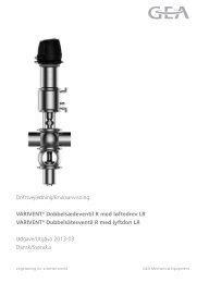
Mechanical<br />
seal<br />
Enkelwerkende<br />
mechanical<br />
seal<br />
LET OP<br />
Pompen met enkele afdichtingen<br />
(zie afbeelding) mogen<br />
nooit langer dan 30 seconden<br />
drooglopen, omdat het oppervlak<br />
van de afdichtingen dan<br />
heet worden en vervormen.<br />
Gebruik daarom gespoelde<br />
afdichtingen wanneer de<br />
pomp moet drooglopen.<br />
Enkelwerkende afdichtingen<br />
zonder spoeling hebben geen<br />
bijzondere installatie nodig.<br />
Enkelwerkende mechanical seal<br />
Single acting mechanical seal<br />
Heating or<br />
cooling<br />
jackets<br />
Heating or cooling jackets<br />
allow to keep the product<br />
temperature constant<br />
and/or to heat cold product<br />
before starting the<br />
pump.<br />
There are heating or cooling<br />
jackets available for<br />
pump covers and heating<br />
jackets laterally fitted to<br />
the pump body.<br />
Application range:<br />
– Pressure for heating<br />
jackets: 2 bar<br />
– Temperature: 130 °C<br />
Mechanical<br />
shaft seals<br />
Single acting<br />
mechanical<br />
seal<br />
CAUTION<br />
Pumps fitted with single<br />
seals (see illustration)<br />
must never be run completely<br />
dry for more than<br />
30 seconds as this will<br />
cause excessive heating of<br />
the seal faces and cause<br />
distruction.<br />
Therefore use flushed<br />
seals in pumps that need<br />
to run dry.<br />
Pumps fitted with single<br />
seals without flush require<br />
no special installation.<br />
10 2008-12 · Lobbenpomp VPSH/VPSU / Rotary Lobe Pump VPSH/VPSU
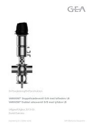
Enkelwerkende<br />
mechanical<br />
seal met spoeling<br />
Bij enkelwerkende<br />
dichtin-gen met spoeling<br />
(zie afbeelding) vormt de<br />
spoelvloeistof (A) een versperring<br />
met lage druk<br />
tussen de pompkamer (B)<br />
en de atmosfeer (C).<br />
Installatie<br />
– Spoelvloeistof op het<br />
produkt afstemmen,<br />
meest gebruikelijke<br />
spoelvloeistof: water<br />
– Druk van de spoelvloei-stof<br />
ca. 0,5 bar<br />
– Maximale watertemperatuur<br />
ca. 70° C, bij<br />
vluchtige spoelvloeistoffen<br />
altijd onder het<br />
kookpunt.<br />
– debiet per afdichting:<br />
0,2 tot 0,3 l/min<br />
– Toevoer van de spoelvloeistof<br />
op het laagste<br />
punt van de spoelkamer,<br />
afvoer op het<br />
hoogste punt om luchtbellen<br />
te voorkomen<br />
– Spoelleidingen volgens<br />
afbeelding monteren.<br />
2008-12 · Lobbenpomp VPSH/VPSU / Rotary Lobe Pump VPSH/VPSU<br />
B<br />
Enkelwerkende mechnical seal met<br />
spoeling<br />
Single flushed mechanical seal<br />
A<br />
overtollig water<br />
waste water<br />
C<br />
Single acting<br />
shaft seal<br />
with flush<br />
Single acting shaft seals<br />
with flush (see illustr.) run<br />
with a low-pressure liquid<br />
flush (A) that forms a barrier<br />
between the pump<br />
chamber (B) and the<br />
atmosphere (C).<br />
Installation<br />
– Flush liquid must be<br />
compatible with the<br />
pumped product, most<br />
commonly used liquid<br />
is water<br />
– Pressure of the flush<br />
liquid approx. 0,5 bar<br />
– Maximum water temperature<br />
approx. 70° C,<br />
for volatile flush<br />
liquids always below<br />
the boiling point.<br />
– Flow rate per seal:<br />
0,2 to 0,3 l/min<br />
– The flush liquid inlet to<br />
be at the lowest point<br />
of the flush chamber,<br />
outlet at the highest<br />
point to vent air bubbles.<br />
– Flush pipes to be installed<br />
as shown in the<br />
illustration.<br />
11
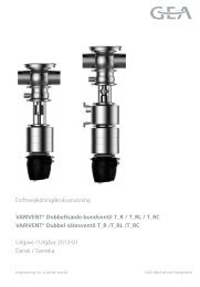
Dubbelwerkende mechanical<br />
seal met spoeling<br />
Bij de dubbelwerkende afdichting<br />
(zie afbeelding)<br />
vormt de spoelvloeistof<br />
(A) een afsperring met<br />
hoge druk tussen de produktzijde<br />
(B) en de atmosfeer<br />
(C).<br />
Installatie<br />
– Gebruik als spoelvloeistof<br />
een vloeistof welke<br />
afgestemd is op het produkt<br />
en welke niet<br />
gevaarlijk of schurend<br />
is.<br />
– Druk van de spoelvloeistof<br />
1 bar boven de<br />
pompdruk<br />
– Debiet per afdichting<br />
ca. 0,2 tot 0,3 l/min<br />
– Toevoer van de spoelvloeistof<br />
op het laagste<br />
punt van de spoelkamer,<br />
afvoer op het<br />
hoogste punt om luchtbellen<br />
te voorkomen<br />
– Spoelleidingen volgens<br />
afbeelding monteren.<br />
B<br />
Dubbelwerkende mechanical seal<br />
met spoeling<br />
Double acting shaft seal with flush<br />
A<br />
Double acting shaft seal<br />
with flush<br />
On double seals, the high<br />
pressure flush liquid (A)<br />
forms a barrier between<br />
the product side (B) and<br />
the atmosphere (C), see<br />
illustration.<br />
Installation<br />
– Use a flush liquid which<br />
is compatible with the<br />
pumped product and<br />
non-abrasive or nonhazardous.<br />
– Pressure of the flush<br />
liquid 1 bar above<br />
pump pressure<br />
– Flow rate per seal:<br />
approx. 0,2 to 0,3 l/min<br />
– The flush liquid inlet to<br />
be at the lowest point of<br />
the flush chamber, outlet<br />
at the highest point<br />
to vent air bubbles.<br />
– Flush pipes to be installed<br />
as shown in the illustration.<br />
12 2008-12 · Lobbenpomp VPSH/VPSU / Rotary Lobe Pump VPSH/VPSU<br />
C
Dubbelwerkende mechnical seal<br />
met stoombarriere<br />
De stoom moet een steriele barriere vormen tussen de<br />
produktzijde en de atmosfeer.<br />
Installatie<br />
– Als spoelvloeistof moet<br />
een steriele vloeistof of<br />
stoomcondensaat<br />
gebruikt worden.<br />
– Wanneer stoom<br />
gebruikt wordt, moet er<br />
veel aandacht geschonken<br />
worden aan de<br />
montage van het leidingwerk.<br />
Ook moet er<br />
controle apparatuur<br />
aanwezig zijn.<br />
– De stoom moet schoon,<br />
gefilterd en nat zijn.<br />
Droge stoom is niet<br />
geschikt.<br />
– De stoomaansluiting op<br />
de spoelkamer moet op<br />
het hoogste punt zijn,<br />
zodat het condensaat op<br />
het laagste punt kan<br />
drainen.<br />
– Gebruik geen carbide<br />
/siliconen carbide/siliconen<br />
afdichtingen voor<br />
stoom gespoelde toepassingen,<br />
omdat de<br />
siliconen kapot gaan bij<br />
hoge temperaturen.<br />
– Installatie is gelijk aan<br />
de installatie van gespoelde<br />
afdichtingen.<br />
2008-12 · Lobbenpomp VPSH/VPSU / Rotary Lobe Pump VPSH/VPSU<br />
Double acting shaft seal<br />
with steam barrier<br />
The steam shall form sterile barrier between the product<br />
side and atmosphere.<br />
Installation<br />
– Sterile liquid or steam<br />
condensate should be<br />
used as flush liquid.<br />
– Where steam is used,<br />
great care must be taken<br />
with the design and<br />
installation of the pipe<br />
work. Monitoring elements<br />
will be required.<br />
– The steam must be<br />
clean, filtered and wet,<br />
i.e. not superheated<br />
– The steam should be<br />
connected to the flush<br />
chamber at the highest<br />
point so that the condensate<br />
can drain at the<br />
lowest point.<br />
– Do not use silicone carbide/silicone<br />
carbide<br />
seals for steam flushed<br />
applications because<br />
silicone gets destroyed<br />
at high temperatures.<br />
– Installation the same as<br />
for flushed seals.<br />
13
Afdichtingsmaterialen<br />
Mechanical seals<br />
Alle produktberoerde afdichtingen zijn in diverse materialen<br />
verkrijgbaar.<br />
Type dichting Toepassing<br />
Carbon/siliconen carbide voor niet schurende media<br />
Siliconen carbide/ voor schurende media,<br />
Siliconen carbide die kristallen en droge substanties<br />
bevatten, niet voor<br />
dichtingen met een stoombarriere<br />
alleen VPSH voor niet schurende en<br />
Carbon/RVS smerende media<br />
Alle niet produktberoerde afdichtingen hebben een<br />
afdichtingsoppervlak van carbon/siliconen carbide.<br />
Elastomeren<br />
Elastomeren die in aanraking komen met produkt moeten<br />
in overeenstemming zijn met het produkt en de procesbesturing.<br />
Hierbij moet rekening gehouden worden<br />
met chemische bestendigheid, temperaturen en de<br />
gevraagde standaards voor materialen.<br />
In de tabel staan de verkrijgbare elastomeren:<br />
VPSH VPSU<br />
Nitril EPDM<br />
EPDM<br />
FPM<br />
FPM<br />
Seal materials<br />
Mechanical seals<br />
All primary seals are available in different materials.<br />
Seal faces Application<br />
Carbon/Silicone carbide for non-abrasive media<br />
Silicone carbide/ for non-abrasive media con-<br />
Silicone carbide taining cristals and dry sub<br />
stances, not recommended for<br />
seals with steam barrier<br />
VPSH only for non-abrasive and lubrica-<br />
Carbon/stainless steel ting media<br />
All secondary double mechanical seals have combined<br />
carbon/silicone carbide faces.<br />
Elastomers<br />
Product contacting elastomers must be compatible with<br />
the product and the process operations. Consideration<br />
must be given to chemical compatibility, temperatures<br />
and required material standards.<br />
The elastomers available are listed in the table below:<br />
VPSH VPSU<br />
Nitril EPDM<br />
EPDM<br />
FPM<br />
FPM<br />
14 2008-12 · Lobbenpomp VPSH/VPSU / Rotary Lobe Pump VPSH/VPSU
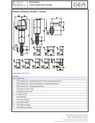
Afsluitplaat<br />
barriere<br />
De pomp VPSU kan geleverd<br />
worden met een sterielbarriere<br />
(A) in de afsluitplaat<br />
(zie afb.). Als<br />
medium voor de barriere<br />
kan stoom of vloeistof<br />
gebruikt worden.<br />
De druk van het steriele<br />
medium mag de 2 bar niet<br />
overschreiden.<br />
Vloeistofbarriere<br />
– De vloeistof in de steriele<br />
barriere moet<br />
afgestemd worden op<br />
de te verpompen vloeistof.<br />
– Toevoer van de steriele<br />
vloeistof op het laagste<br />
punt van de afsluitplaat,<br />
afvoer op het hoogste<br />
punt om luchtbellen te<br />
voorkomen.<br />
– Installatie volgens de<br />
afbeelding.<br />
Stoombarriere<br />
– Stoomdruk zo laag<br />
mogelijk<br />
– Temperatuur constant<br />
houden<br />
– De stoomaansluiting op<br />
de afsluitplaat moet op<br />
het hoogste punt zijn,<br />
zodat het condensaat op<br />
het laagste punt kan<br />
drainen.<br />
– Installatie volgens de<br />
afbeelding.<br />
2008-12 · Lobbenpomp VPSH/VPSU / Rotary Lobe Pump VPSH/VPSU<br />
A<br />
Afsluitplaat barriere<br />
End cover barrier<br />
overtollig water<br />
waste water<br />
End cover<br />
barrier<br />
The pump VPSU may also<br />
be fitteed with an end<br />
cover to accommodate a<br />
sterile barrier (A) of sterile<br />
liquid or steam<br />
(see illustration).<br />
The pressure of the sterile<br />
medium must not exceed<br />
2 bar.<br />
Liquid barrier<br />
– The liquid in the sterile<br />
barrier must be compatible<br />
with the pumped<br />
liquid.<br />
– The inlet of the sterile<br />
medium should be<br />
connected at the<br />
lowest point of the end<br />
cover, the outlet at the<br />
highest point to vent<br />
air bubbles.<br />
– Carry out the installation<br />
acc. to the illustration.<br />
Steam barrier<br />
– Steam pressure to be as<br />
low as possible<br />
– Keep the temperature<br />
constant<br />
– The inlet of the steam<br />
should be connected at<br />
the lowest point of the<br />
end cover, the outlet at<br />
the highest point to<br />
drain condensate.<br />
– Carry out the installation<br />
acc. to the illustration.<br />
15
Overbelastingsprotectie<br />
GEVAAR<br />
Door overdruk op de pomp kunnen mensen gewond en<br />
de pomp beschadigd raken. Daarom moeten de volgende<br />
veiligheidsapparatuur ge-installeerd worden:<br />
– Drukschakelaar of sensor die motor stopt bij overdruk.<br />
In combinatie met motorrem is meest ideaal.<br />
– Veiligheidsventiel of breekplaatje aan de afvoerzijde<br />
van de pomp.<br />
– Overbelastingskoppeling tussen pomp en motor<br />
– Motor overbelastingsschakelaar<br />
✗De overbelastingskoppeling tussen pomp en motor en<br />
de motor overbelastingsschakelaar zijn moeilijk in te<br />
stellen – vooral wanneer er viscose media verpompt<br />
wordt.<br />
Het veiligheidsniveau van de drukschakelaar, het veiligheidsventiel<br />
en en de overdrukprotectie op het deksel<br />
zijn hoger.<br />
Smering<br />
De pompen worden zonder olie in het aandrijfhuis geleverd.<br />
• Kijk op het gevensblad van de bepaalde pomp voor de<br />
juiste hoeveelheid olie.<br />
• Neem de olie die juist is voor de omgevingstemperatuur<br />
ter plekke (zie tabel). Bij het verpompen van<br />
hete vloeistoffen of als de aandrijving tijdens gebruik<br />
heter dan 80° C wordt, moet olie voor hoge temperaturen<br />
gebruikt worden.<br />
Omgevingstemperatuur Type olie<br />
– 18° C bis 0° C EP 150<br />
0° C bis 30° C EP 220<br />
30° C bis 80° C EP 320<br />
• Vullen met olie voor in gebruikname.<br />
•Na de eerste 120 bedrijfsuren de aandrijfolie vervangen.<br />
• Regelmatig het oliepeil in de aandrijving controleren<br />
en, indien nodig bijvullen.<br />
• Bij elk groot olieverlies direct een onderzoek instellen.<br />
Overload protection<br />
DANGER<br />
To prevent injury to personnel or damage to the pump<br />
or system caused by excessive pressures, a protection<br />
device should be fitted, such as:<br />
– Pressure switch or sensor to stop the motor. Ideally, in<br />
combination with a motor brake.<br />
– Pressure relief valve or bursting disk fitted in the<br />
system downstream the pump<br />
– Torque limiting coupling between pump and motor<br />
– Motor overload switch<br />
✗The torque limiting coupling between pump and<br />
motor and the motor overload switch are difficult to<br />
adjust accurately – especially when pumping viscous<br />
media.<br />
The level of protection of the pressure switch, relief<br />
valve and the excess pressure protection at the cover<br />
are superior.<br />
Lubrication<br />
The pumps are supplied without oil in the gear box.<br />
• Refer to performace data sheet of the specific pump<br />
for the required amount of oil.<br />
• Select the oil to conform to the local ambient temperatures<br />
(see table). If pumping hot liquids or if the gear<br />
during operation reaches more than 80° C , use high<br />
temperature oil.<br />
Ambient temperature Oil grade<br />
– 18° C to 0° C EP 150<br />
0° C to 30° C EP 220<br />
30° C to 80° C EP 320<br />
• Fill-in oil before commissioning.<br />
• After the first 120 hours of service, exchange gear oil.<br />
• Check gear oil level regularly and refill if necessary.<br />
• Any substantial oil losses should be investigated<br />
immediately.<br />
16 2008-12 · Lobbenpomp VPSH/VPSU / Rotary Lobe Pump VPSH/VPSU
De olie moet elke jaar of na 2500 bedrijfsuren vervangen<br />
worden.<br />
Olie voor hoge temperaturen moet elk half jaar of na<br />
1000 bedrijfsuren vervangen worden.<br />
In gebruik name<br />
GEVAAR<br />
Voor de eerste in gebruik-name of na onderhoud of<br />
reparatie, moet de pomp gecontroleerd worden volgens<br />
onderstaande checklist – door dit niet te doen kan er<br />
beschading aan de pomp of verwon-dingen aan personen<br />
komen:<br />
– Alle bouten en schroe-ven op het pomphoofd en andere<br />
geschroefde onderdelen moeten goede aangedraaid<br />
zijn<br />
– Alle leidingaansluitingen moeten dicht zijn.<br />
– Alle veiligheidsen beschermingsapparatuur moet geinstalleerd<br />
zijn en werken.<br />
– Bij gespoelde dichtingen moet de spoelvloeistof stromen.<br />
– Alle ventielen moeten geopend zijn. NOOIT tegen een<br />
gesloten ventiel pompen.<br />
– Let op de draairichting<br />
bij het aansluiten van<br />
de motor (zie afb.).<br />
– Pomp en leidingen moeten<br />
vrij zijn van lasslakken<br />
en andere “vreemde”<br />
voorwerpen.<br />
2008-12 · Lobbenpomp VPSH/VPSU / Rotary Lobe Pump VPSH/VPSU<br />
Oil change every 12 months or after every 2.500 operating<br />
hours.<br />
Change high temperature oil every 6 months or after<br />
every 1.000 operating hours.<br />
Commissioning<br />
DANGER<br />
Before starting the pump for the first time or after<br />
maintenance or repair work, check the pump according<br />
to the below check list – failure to do so may damge the<br />
equipment or cause injury to the personnel:<br />
– All bolts and screws at the pump head and other<br />
fixing elements to be tight.<br />
– All pipe connections to be secure.<br />
– All safety and protection devices to be in place and<br />
functionable.<br />
– For flushed seals, flushing medium must flow.<br />
– All valves to be opened. NEVER run pump against a<br />
closed valve.<br />
– When connecting the<br />
motor, observe correct<br />
sense of direction (see<br />
illustration).<br />
– Pump and pipes to be<br />
clear of welding flash or<br />
other debris.<br />
17
– Gebruik de pomp nooit voor de eerste reiniging van<br />
het systeem. Het systeem met een daarvoor bestem-de<br />
pomp en reinigingsmiddel doorspoelen. Zorg er voor<br />
dat metaaldelen en ander “vreemde” materialen zich<br />
op het laagste punt in het systeem verzamelen.<br />
– De pomp moet correct met olie gevuld zijn.<br />
.<br />
GEVAAR<br />
Alle oppervlakken die tijdens het in bedrijf zijn heet<br />
worden, b.v. boven de 60°C, moeten stickers met waarschuwingen<br />
hiervoor bevatten.<br />
– Leidingen en pomphoofd (indien verwarmd) moeten<br />
de bedrijfstemperatuur bereikt hebben.<br />
– Indien mogelijk, de pomp langzaam starten.<br />
– Let op onverwachtte geluiden.<br />
– Controleren op lekken.<br />
– Controleren of de pomp het gewenste debiet bereikt.<br />
– Pomp stoppen als er geen vloeistof stroomt. Drooglopen<br />
kan de dichtingen beschadigen.<br />
– De pomp tijdens de eerste bedrijfsuren regelmatig<br />
controleren. Controleer op abnormale geluiden en<br />
zeer hoge temperaturen van het aandrijfhuis, b.v.<br />
boven de 80 °C, tenzij er hete vloeistoffen verpompt<br />
worden, waarbij de 110°C bereikt kan worden.<br />
– NEVER use the pump for cleaning the system for the<br />
first time. Flush the whole system using a suitable<br />
cleaning pump and detergents. Be aware that heavy or<br />
metal debris tend to collect at the lowest point in the<br />
system.<br />
– See to it that the pump is correctly filled with oil.<br />
DANGER<br />
All surfaces which heat up during operation, e.g. more<br />
than 60°C should carry warning labels.<br />
– Pipes and the pump head (if heated) must have reached<br />
their operating temperature.<br />
– If possible, start pump slowly.<br />
– Listen for unexpected noises.<br />
– Check for leaks.<br />
– Check that pump gives the desired flow rate.<br />
– Stop the pump if liquid is not flowing, dry run can<br />
damage seals.<br />
– Observe the pump during the first operating hours.<br />
Check for abnormal noises and excessive temperatures<br />
of the pump gear box, i.e. above 80 °C, unless<br />
pumping hot liquids when 110°C may be reached.<br />
18 2008-12 · Lobbenpomp VPSH/VPSU / Rotary Lobe Pump VPSH/VPSU
Reiniging en<br />
Sterilisatie<br />
De pompen VPSH ens VPSU zijn zo ontworpen dat ze<br />
in het proces gereinigd kunnen worden.<br />
De graad van reiniging is afhankelijk van de eisen van<br />
het proces en het produkt. De hier gegeven informatie<br />
dient slechts als richtlijn. Het is de verantwoordelijkheid<br />
van de gebruiker, dat de mate van reiniging voldoet aan<br />
de vereisten van produkt en proces.<br />
Er zijn 3 manieren van reinigen<br />
– handmatige reiniging<br />
– CIP (clean in place)<br />
– SIP (sterilize in place)<br />
Bij handmatige reiniging moet de pomp ontmanteld<br />
worden.<br />
Bij CIP- en SIP-reiniging wordt de pomp doorgespoeld<br />
met reinigingsvloeistof en/of stoom.<br />
De pomp VPSH is goed geschikt voor CIP- en SIP-reiniging.<br />
Daarnaast is de pomp snel te ontmantelen en<br />
handmatig te reinigen.<br />
De pomp VPSU is zeer geschikt voor CIP- en SIP-reiniging,<br />
maar is minder goed geschikt voor handmatige<br />
reiniging.<br />
De manier van reinigen hangt af van het gewenste resultaat<br />
en de mate van vervuiling. Organische materialen,<br />
zoals vetten, olien en proteinen, vragen een heel andere<br />
manier/soort reiniging dan anorganische materialen,<br />
zoals mineraalzouten. De reinigingsmiddel-enfabrikant<br />
kan een advies geven over het juiste gebruik van een reinigingsmiddel.<br />
Een CIP-reiniging vraagt om een debiet<br />
van 1,5 m/s in het leidingwerk om een goede turbulente<br />
stroming te verkrijgen.<br />
CIP-reiniging<br />
Elke pomp wordt geheel schoon geleverd. De gebruiker<br />
is er voor verantwoordelijk dat de pomp gereinigd<br />
wordt voordat de pomp voor het eerst gestart wordt.<br />
De volgende richtlijnen helpen bij een effectieve reiniging<br />
en minimalizeren het risico op beschadiging<br />
.<br />
Spoelvloeistof<br />
– De pomp met een geschikte vloeistof spoelen – over<br />
het algemeen water van ca. 50°C – en dit zo snel<br />
mogelijk na be-eindigen van het produktieproces om<br />
te voorkomen dat het residu opdroogt op de oppervlakken.<br />
2008-12 · Lobbenpomp VPSH/VPSU / Rotary Lobe Pump VPSH/VPSU<br />
Cleaning and<br />
Sterilization<br />
The pumps VPSH and VPSU are designed that they are<br />
cleaned in the process.<br />
The degree of cleaning or sterilization depends on the<br />
needs of the process and product. The information given<br />
here is provided for guidance only. It is within the responsibility<br />
of the pump user that the cleaning cycle chosen<br />
is adequate to achieve the desired degree of cleanliness.<br />
There are 3 types of cleaning<br />
– manual cleaning<br />
– CIP (clean in place)<br />
– SIP (sterilize in place)<br />
For manual celaning the pump must be dismantled.<br />
In the CIP/SIP cleaning method, the pump is flushed<br />
with cleaning agents and/or steam.<br />
The pump VPSH is most suitable for the CIP and SIP<br />
method. Equally the pump can be quickly stripped to<br />
gain access to all liquid contacted areas.<br />
The pump VPSU offers an exceptonally high standard<br />
for CIP/ SIP, but is less suitable for manual cleaning.<br />
The type of the cleaning method/system depends partly<br />
on the level of cleaning required, but also on the type of<br />
inproperties to be removed. Organic materialials, such<br />
as oils, fats and proteins need a different cleaning<br />
method/system to inorganic materials such as mineral<br />
salts. Detergent manufacturers can give advice on the<br />
correct use of detergents. CIP usually needs a flow velocity<br />
of 1,5 m/s through the pipe to achieve the turbulent<br />
flow required.<br />
Cleaning-in-Place (CIP)<br />
Each pump is supplied in a generally clean condition,<br />
but it is the responsibility of the user to clean the pump<br />
pior to the pump`s first start-up.<br />
The following guidelines will help with effective cleaning<br />
and minimize the risk of damage to the pump.<br />
Rinsing liquid<br />
– Rinse the pump via the system with a suitable liquid,<br />
usually water at approx. 50°C – and that as soon as<br />
possible after completion of the production process to<br />
remove residues before they dry onto surfaces.<br />
19
– Wanneer direct aansluitend geen CIP-reiniging wordt<br />
uitgevoerd, moet men het eerste spoelwater in de<br />
pomp en het leidingwerk laten staan.<br />
Reinigingsmiddelen<br />
– Gebruik de reinigingsmiddelen in concentratie, temperatuur<br />
en tijd als aangegeven in de instructies van<br />
de fabrikant.<br />
– De reinigingstemperatuur mag hierbij niet boven de<br />
90°C komen.<br />
– Controleer of het materiaal van de pomp bestand is<br />
tegen het reinigingsmiddel<br />
.<br />
Debiet<br />
– De ClP-vloeistof moet in de hoofdleiding een debiet<br />
van tenminste 1,5 m/s bereiken.<br />
– Wanneer een lobbenpomp wordt gebruikt voor de circulatie<br />
van de CIP-vloeistof, gebruik dan het technisch<br />
gegevensblad om het toertal en het benodigde debiet<br />
van de pomp in te stellen. Let er op dat er rekening<br />
gehouden wordt met het drukverlies in het systeem.<br />
Houdt er ook rekening mee dat alle pompen bij hete<br />
vloeistoffen sneller cavitatie kunnen krijgen. Zorg er<br />
dus voor dat er voldoende druk op de aanzuigzijde<br />
staat.<br />
– Wanneer er een aparte CIP-pomp gebruikt wordt,<br />
moet de lobbenpomp met een voldoende toerental<br />
meedraaien om een toereikende vloeistofstroom door<br />
de pomp te krijgen. Wanneer hierdoor geen voldoende<br />
debiet in het leidingwerk bereikt kan worden, moet er<br />
een bypass aangelegd worden, zodat er een toereikende<br />
vloeistofstroom langs de pomp geleid kan worden.<br />
Druk<br />
– De druk van de CIP-reiniging moet gelijk of hoger zijn<br />
aan de procesdruk om te bereiken dat alle oppervlakken<br />
goed gereinigd worden.<br />
– Het kan nodig zijn om de doorstroming in het systeem<br />
aan de drukzijde te knijpen.<br />
– De druk mag niet boven de differenciaaldruk van de<br />
pomp uitkomen (zie gegevensblad van de pomp).<br />
Voor een effectieve reiniging wordt een differenciaaldruk<br />
van tenminste 1 bar aanbevolen.<br />
– If CIP is not carried out immediately after rinsing<br />
leave the first rinsing water in the pump and system.<br />
Cleaning agents<br />
– Use cleaning agents in concentration, temperature and<br />
times according to the manufacturer`s instructions.<br />
– The cleaning temperature should not exceed 90°C .<br />
– Check the compatibility of the cleaning agent with the<br />
pump`s material of construction.<br />
Flow velocity<br />
– ClP fluid flow must reach in the main pipe a flow<br />
velocity of at least 1,5 m/s.<br />
– If using a lobe pump to circulate CIP fluid, refer to the<br />
performance data sheet for fixing the speed and the<br />
required flow rate for the pump. Take the system`s<br />
pressure drops into account and note that all pumps<br />
are more susceptible to caviation when pumping hot<br />
liquids. Therefore ensure sufficient net inlet pressure .<br />
– If using a separate pump to circulate the CIP fluid, the<br />
lobe pump may need to be rotated at a speed sufficiently<br />
high to allow a sufficient amount of fluid to<br />
pass the pump freely. If sufficient pipe velocity cannot<br />
be achieved, fit a by-pass loop to divert excess flow<br />
past the pump.<br />
Pressure<br />
– The CIP fluid pressure must be equal to or exceed the<br />
system pressure to ensure that the fluid reaches all<br />
contact surfaces.<br />
– It may be necesary to restrict the system flow at the<br />
pressure side.<br />
– The pressure must not exceed the differential pressure<br />
and the temperatures of the pump shown on the<br />
pump performance data sheet. A minimum differential<br />
pressure of at least 1 bar is recommended for effective<br />
cleaning.<br />
20 2008-12 · Lobbenpomp VPSH/VPSU / Rotary Lobe Pump VPSH/VPSU
Na de reiniging<br />
– Na de CIP-reiniging moet er gespoeld worden met een<br />
neutralizerende vloeistof en water, zodat er geen<br />
resten van de reinigingsvloeistof achterblijven.<br />
LET OP<br />
Laat geen koude vloeistoffen vlak na de hete reiniging<br />
door het systeem stromen. Door te snel afkoelen kan de<br />
pomp beschadigd raken.<br />
Handmatig reinigen<br />
GEVAAR<br />
Alvorens de pomp te demonteren moet de stekker uit<br />
het stopkontakt worden gehaald of de hoofdschakelaar<br />
omgedraaid worden en de zekering eruit gedraaid. Het<br />
pomphuis moet vrij van druk en gedraind zijn en de<br />
kamertemperatuur hebben aangenomen. De afsluitapparatuur<br />
in de zuig- en drukleiding moeten gesloten<br />
zijn.<br />
Oppervlakken, vooral die van de dichtingen, niet<br />
beschadigen.<br />
Gebruik geen schuursponsjes of staalborstels op produktberoerende<br />
oppervlakken, omdat dan deeltjes zich<br />
in het oppervlak kunnen nestellen en corrosie kunnen<br />
veroorzaken.<br />
Gebruik geschikte reinigingsmiddelen en volg de<br />
instructies van de fabrikant.<br />
• Het vloeistofberoerde deel van de pomp ontmantelen.<br />
Bij deze manier van reinigen moeten in ieder geval de<br />
rotoren en de sluitplaat verwijderd worden.<br />
• Na de reiniging de pomp volgens de montage-instructies<br />
weer in elkaar zetten.<br />
2008-12 · Lobbenpomp VPSH/VPSU / Rotary Lobe Pump VPSH/VPSU<br />
After cleaning<br />
– After CIP, rinse through with neutralizers and clean<br />
water to remove all traces of cleaning agents left in the<br />
system.<br />
CAUTION<br />
Do not circulate cold liquid through the pump immediately<br />
after hot cleaning. Allow temperature to decrease<br />
slowly as otherwise the pump may get damaged.<br />
Manual cleaning<br />
DANGER<br />
Prior to dismantling the pump, pull the mains plug or<br />
switch off the main switch and deactivate the fuse, in<br />
order to secure the pump against inadvertent starting.<br />
The pump housing must be depressurized, empty and<br />
cooled down to room temperature. The shut-off devices<br />
in the suction and pressure pipes must be closed.<br />
Take care not to scratch or damage pump parts, especially<br />
seal faces.<br />
Do not use steel abrasive wool or wire brushes on fluid<br />
wetted surfaces, as particles may become embedded in<br />
the surface and cause corrosion.<br />
Use suitable cleaning agents in accordance with the<br />
manufacturer`s instructions.<br />
• Dismantle the fluid contact parts of the pump. As a<br />
minimum it will be necessary to remove the end cover<br />
and the rotors.<br />
• Re-assemble the pump after cleaning according to the<br />
mounting intructions.<br />
21
SIP-Reiniging<br />
Het is mogelijk om stoom door het systeem te voeren en<br />
zo de binnen oppervlakken te steriliseren zonder dat de<br />
pomp ontmanteld moet worden.<br />
Om steriliteit te bereiken is het bevordelijk om de stoom<br />
zo lang door het systeem te leiden, tot de oppervlakken<br />
een zo’n hoge temperatuur bereikt hebben dat alle<br />
micro-organismen gedood worden.<br />
Bij een chemische sterilisatie wordt gewerkt als bij een<br />
CIP-Reiniging.<br />
Als er stoom gebruikt wordt, moet hier bij de pompkeuze<br />
reeds rekening mee gehouden worden.<br />
Dichtingen<br />
LET OP<br />
Steriliseer NOOIT enkelwerkende mechanical seals met<br />
siliconen carbide/siliconen carbide oppervlak.<br />
– EPDM is voor herhaalde stoomsterilisatie goed<br />
geschikt, maar moet regelmatig vervangen worden<br />
– PTFE (Teflon) is het slechts geschikt voor contact met<br />
stoom. PTFE-sluitplaatdichtingen moeten na elke<br />
stoomsterilisatie vervangen worden.<br />
Alvorens te steriliseren<br />
– De pomp moet gemonteerd zijn met verticaal staande<br />
aansluitingen, zodat deze zelf-drainend is en er geen<br />
vloeistof in de pomp kan blijven staan.<br />
– De pomp en het systeem voor de sterilisatie zorgvuldig<br />
reinigen.<br />
– Wanneer de pomp is uitgerust met sterielbarrieres<br />
(asdichtingen en kap) moet het barriere vloeistofsysteem<br />
aangesloten blijven om een her-infectie te<br />
voorkomen.<br />
Sterilization-in-Place (SIP)<br />
It is possible to pass steam through the system and to<br />
sterilize the internal surfaces without the need of dismantling<br />
the pump.<br />
To achieve sterility, it is important to steam through the<br />
system for a period long enough to allow that all surfaces<br />
reach a sufficiently high temperature to kill off<br />
micro-organisms.<br />
If using chemical sanitizers, follow the guidelines as<br />
described before for CIP.<br />
If using steam, the following must be taken into account<br />
at the time of selecting the pump:<br />
<strong>Seals</strong><br />
CAUTION<br />
NEVER sterilze single-acting mechanical seals with silicone<br />
carbide/silicone carbide face.<br />
– EPDM offers best resistance to repeated steam contact,<br />
but will need to be changed at regular intervals.<br />
– PTFE (Teflon) is at least suitable for steam contact.<br />
PTFE end cover joints may need to be replaced every<br />
time the pump is sterilized.<br />
Prior to sterilization<br />
– The pump should be mounted with the port axis vertical<br />
to ensure self-draining and thus avoid liquid pools.<br />
– Thoroughly clean pump and system prior to sterilization.<br />
– If the pump is fitted with sterile barriers (shaft seals<br />
and cover), the barrier fluid system must be connected<br />
throughout the SIP cycle to avolid re-infection.<br />
22 2008-12 · Lobbenpomp VPSH/VPSU / Rotary Lobe Pump VPSH/VPSU
Sterilisatie procedure<br />
GEVAAR<br />
De hete stoom kan tot zware verwondingen leiden.<br />
Open in geen geval de pompkap of een andere aansluiting<br />
tijdens het sterilisatieproces.<br />
De stoom t.b.v sterilisatie moet vrij zijn van kalk, roest<br />
en andere deeltjes. Indien nodig, een filter gebruiken.<br />
• Voer schone, natte stoom door het systeem totdat de<br />
temperatuur in het systeem zich gestabiliseerd heeft.<br />
• De benodigde opwarmtijd is systeemafhankelijk en<br />
moet met temperatuurvoelers nauwkeurig vastgesteld<br />
worden. De pomp mag tijdens dit proces niet<br />
draaien.<br />
LET OP<br />
Tijdens de sterilisatie kunnen de oppervlakken van de<br />
pomp zeer heet worden, aanraking kan verbranding tot<br />
gevolg hebben.<br />
Duur van de sterilisatie<br />
– De duur van de sterilisatie is afhankelijk van het gebruik<br />
en de mate van steriliteit van het systeem.<br />
– Over het algemeen is de sterilistatieduur 20 tot 60<br />
minuten.<br />
– De lobbenpomp mag alleen draaien als het strikt<br />
noodzakelijk is om een optimale steriliteit te bereiken.<br />
Alle pomponderdelen bereiken over het algemeen de<br />
gewenst temperatuur, zonder dat de pomp draait.<br />
Indien nodig, dan de pomp handmatig gedraaid worden<br />
of met een maximum toerental van 50 rpm, indien<br />
de pomp enkelwerkende dichtingen van carbon/siliconen<br />
carbide heeft.<br />
Als er gespoelde of dubbelwerkende dichtingen<br />
gebruikt zijn, kan de pomp ook draaien met een maximum<br />
toerental van 50 rpm, alleen als de<br />
spoel/barriere vloeistof (b.v. condensaat) stroomt. De<br />
druk van de spoel/barierre vloeistof moet hoger zijn<br />
dan de druk van de sterilisatiestoom.<br />
2008-12 · Lobbenpomp VPSH/VPSU / Rotary Lobe Pump VPSH/VPSU<br />
SIP Procedure<br />
DANGER<br />
Hot steam my cause severe bodily injury. NEVER loosen<br />
the pump cover or connections during the sterilization<br />
process.<br />
Steam used for sterilization must be free from lime, rust<br />
and other particles. Use a filter, if necessary.<br />
• Pass clean, wet steam through the system until the<br />
system temperature has stabilized.<br />
• The heating time needed depends on the system and<br />
must be precisely ascertained using temperature sensors.<br />
Do not rotate the pump during this heating<br />
phase.<br />
CAUTION<br />
During sterilization, the surfaces of the pump may get<br />
very hot and any contact with the pump may cause burnings.<br />
Soak time<br />
– The soak time depends on the application and the<br />
required sterility level of the system.<br />
– Soak time is typically 20 to 60 minutes.<br />
– The rotary lobe pump should not run during this hold<br />
time unless absolutely essential to achieve sterility.<br />
All pump components will normally reach the desired<br />
temperature by thermal conduction without rotating<br />
the pump.<br />
If essential, the pump can be rotated during the hold<br />
time by hand or at maximum speed of 50 rpm, if the<br />
pump is fitted with single acting carbon/silicone<br />
carbid seals .<br />
If flushed or double-acting seals are used, the pump<br />
may also run at maximum speed of 50 rpm, provided<br />
liquid flush/sealing flush, (e.g. with condensate) are<br />
connected and are operating at a pressure above the<br />
steam pressure within the pump during SIP .<br />
23
Wanneer de pomp is uitgerust met een enkelwer-kende<br />
siliconen carbide/siliconen carbide dichting, mag<br />
de pomp niet meedraaien,omdat de afdichtvlak-ken<br />
zich dan met elkaar kunnen versmelten.<br />
– Aan het einde van de sterilisatietijd moet de pomp<br />
afkoelen. Deze tijd kan door steriele lucht of gas verkort<br />
worden. Tijdens de afkoelperiode mag de pomp<br />
niet draaien.<br />
– De pomp mag niet abrupt afgekoeld worden (b.v.<br />
door koud water).<br />
– Wanneer de pomp is uitgerust met siliconen carbide/<br />
siliconen carbide dichtingen, dan mag de pomp pas<br />
draaien als het pomphoofd gevuld is met vloeistof.<br />
Inspectie en reparatie<br />
van het pomphoofd<br />
De pompen VPSH en VPSU zijn vrijwel geheel onderhoudsvrij.<br />
Toch is het nodig om regelmatig het oliepeil<br />
te controleren.<br />
Om eventuele storing te voorkomen adviseert <strong>Tuchenhagen</strong><br />
om regelmatig het pomphoofd visueel te inspecteren.<br />
Hierbij moet bijzondere aandacht gegeven worden<br />
aan de dichtingen en aansluitingen en de correcte<br />
werking van de pomp.<br />
Alle hoofddichtingen kunnen ge-inspecteerd worden<br />
zonder dat de pomp uit het systeem gehaald moet worden.<br />
LET OP<br />
De pomp moet volledig gedraind worden voordat men<br />
deze demonteerd. Als er zich gevaarlijke vloeistoffen in<br />
de pomp bevinden, zorg dat deze goed en veilig<br />
gedraind, behandeld en afgevoerd worden<br />
GEVAAR<br />
Voor elke demontage moet de stekker uit het stopcontact<br />
gehaald worden of de hoofdschakelaar uit gezet<br />
worden en de zekering gedeactiveerd worden, om te<br />
voorkomen dat de pomp kan starten. Het pomphuis<br />
moet drukvrij en gedraind zijn en de kamertemperatuur<br />
hebben aangenomen. De afsluitapparatuur in de zuigen<br />
drukleiding moet gesloten zijn.<br />
If the lobe pump is fitted with single-acting silicone<br />
carbide/silicone carbide seals, the pump must not be<br />
rotated during the hold time as the seal faces can bind<br />
together.<br />
– At the end of the hold time, the pump must be allowed<br />
to cool naturally. This time may be shortened by<br />
applying sterile air or gas. The pump must not run<br />
during the cooling phase.<br />
– The pump must not cool abruptly (e.g. by cold water).<br />
– If the pump is fitted with silicone carbide/silicone carbide<br />
seals, the pump may rotate when the pump head<br />
is filled with liquid.<br />
Inspection and<br />
repair of the pump<br />
head<br />
The pumps VPSH and VPSU are virtually maintenance<br />
free. It is advisable though, to check the oil level at regular<br />
intervals.<br />
As a preventive measure, <strong>Tuchenhagen</strong> recommends to<br />
carry out visual inspections of the pump head components<br />
periodically, (seals and joints) and to pay particular<br />
attention to tightness and the correct function of the<br />
pump.<br />
All main seals may be inspected without the need of<br />
removing the pump from the system.<br />
CAUTION<br />
Prior to dismantling, the pump must completely be<br />
drained. If the pump contains dangerous liquids, take<br />
care that these liquids are properly drained, handled<br />
and disposed of.<br />
DANGER<br />
Prior to dismantling the pump, pull the mains plug or<br />
switch off the main switch and deactivate the fuse, in<br />
order to secure the pump against inadvertent starting.<br />
The pump housing must be depressurized, empty and<br />
cooled down to room temperature. The shut-off devices<br />
in the suction and pressure pipes must be closed.<br />
24 2008-12 · Lobbenpomp VPSH/VPSU / Rotary Lobe Pump VPSH/VPSU
• Electriciteit voor de pompmotor verbreken.<br />
• Het pomphuis uit het leidingwerk halen, drainen en af<br />
laten koelen tot kamertemperatuur.<br />
Afsluitplaat<br />
Afsluitplaat VPSH<br />
End cover VPSH<br />
Demonteren<br />
Afsluitplaat VPSU<br />
End cover VPSU<br />
LET OP<br />
Voordat men de afsluitplaat (73) verwijderd, moet men<br />
er zeker van zijn dat de pomp niet is aangesloten op het<br />
electrisch net, drukvrij en gedraind is. Dit geldt ook<br />
voor de verwarmingsmantels en de dichtings vloeistofbarrieres.<br />
Let er in het bijzonder op dat de pomp koud is en geen<br />
gevaarlijke vloeistoffen meer bevat. Wanneer de pompkap<br />
is uitgerust met een veiligheidsventiel, zie de<br />
beschrijving in het onderdeel „Overbelastingsprotectie“.<br />
LET OP<br />
De afsluitplaat (73) is zwaar. Houdt de afsluitplaat goed<br />
vast wanneer de bouten (39) verwijderd worden.<br />
Beschadig de oppervlakken en dichtingen niet.<br />
• Verwijder de bouten (39). Mocht de afsluitplaat (73)<br />
“plakken”, tik dan voorzichtig zijdelings met een rubber<br />
hamer.<br />
• Leg de afsluitplaat met de produktzijde naar boven op<br />
een schoon oppervlak.<br />
2008-12 · Lobbenpomp VPSH/VPSU / Rotary Lobe Pump VPSH/VPSU<br />
• Disconnect the pump motor .<br />
• Dismount the pump housing from the pipe system,<br />
drain and let it cool down to room temperature.<br />
End cover<br />
Removal<br />
Afsluitplaat met barriere VPSU<br />
End cover with barrier VPSU<br />
CAUTION<br />
Before removing the end cover (73), make sure that the<br />
pump is disconnected from the mains, the system is<br />
depressurized and drained of liquids. The same applies<br />
to heating jackets and the seal flushing system.<br />
See to it, that the pump is cold and does not contain<br />
hazardous fluids. If the pump cover is fitted with a<br />
safety valve refer to the relevant description in section<br />
„Overload protection“<br />
CAUTION<br />
The end cover (73) is heavy. Take care to support the end<br />
cover, when removing the bolts (39).<br />
Take care not to damage the seal`s surface. .<br />
• Remove bolts (39). If the end cover (73) "sticks", tap<br />
carefully sideways with a rubber hammer.<br />
• Place the end cover with product side upwards on a<br />
clean surface.<br />
25
Monteren<br />
VPSH<br />
• Plaats de O-ring (74) in de groef in de afsluitplaat,<br />
zorg dat deze vlak in de groef zit.<br />
VPSU<br />
• Plaats de afdichting (74) in de groef in de afsluitplaat,<br />
zorg dat deze vlak in de groef zit. Om vervorming te<br />
voorkomen, de afdichting op 4 plaatsen vast drukken,<br />
daarna de rest in de groef drukken.<br />
• Plaats de bouten (39).<br />
•Controleer of de afsluitplaat op de juiste wijze op het<br />
pomphuis zit.<br />
• De bouten met het juiste draaimoment aandraaien.<br />
Installation<br />
VPSH<br />
• Place the O-ring (74) in the end cover groove, ensuring<br />
that it seats evenly.<br />
VPSU<br />
• Place the joint seal (74) in the end cover groove, ensuring<br />
that it seats evenly. To avoid forming loops, press<br />
in the seal at 4 places first and then press the rest.<br />
• Insert bolts (39).<br />
•Check that end cover is correctly located on the pump<br />
housing.<br />
• Tighten bolts to the correct torque.<br />
26 2008-12 · Lobbenpomp VPSH/VPSU / Rotary Lobe Pump VPSH/VPSU
Rotoren<br />
Demontage<br />
• Ontkoppel de pomp<br />
van de motor.<br />
• Afsluitplaat verwijderen<br />
(zie deel „afsluitplaat“.)<br />
VPSH<br />
De rotoren zijn vastgezet<br />
met speciale geborgde<br />
schroeven – de rotorbout<br />
(7). De rotorbouten worden<br />
afgedicht door een Oring<br />
(63).<br />
• De rotoren worden geblokkerd<br />
met een zacht<br />
kunststof blok (wordt<br />
bij elke pomp geleverd)<br />
(zie afbeelding).<br />
✗Beide rotorbouten (7)<br />
hebben rechts draaiende<br />
draad.<br />
• Draai de rotorbouten<br />
los met het speciaal<br />
hier-voor meegeleverde<br />
gereedschap.<br />
LET OP<br />
Let op dat de vlakken van<br />
de mechanical seals op de<br />
as en in de rotor niet<br />
beschadigd raken bij het<br />
verwijderen van de rotor.<br />
• Verwijder de rotor voorzichtig.<br />
• Markeer de rotoren zo,<br />
dat ze bij montage weer<br />
op de juiste as komen<br />
en ook juist op het<br />
dichtvlak van de<br />
mechanical seals komen<br />
te zitten.<br />
Blokkeren van de rotoren<br />
Onderste rotor vrijmaken<br />
Locking the rotors<br />
Loosen the bottom rotors<br />
2008-12 · Lobbenpomp VPSH/VPSU / Rotary Lobe Pump VPSH/VPSU<br />
Rotors<br />
Removal<br />
• Disconnect the pump<br />
from the motor drive.<br />
• Remove end cover (see<br />
section „End cover“).<br />
VPSH<br />
The rotors are secured by<br />
special slotted screws –<br />
the rotor bolt (7). The<br />
rotor bolts are sealed by<br />
O-rings (63).<br />
• The rotors are locked<br />
using a soft plastic<br />
block (delivered with<br />
each pump), see illustration<br />
✗Both rotor bolts (7) have<br />
a right-hand thread.<br />
• Loosen the rotor bolts<br />
(7) with the special tool<br />
supplied.<br />
CAUTION<br />
Take care not to damage<br />
the sealing face of the<br />
mechanical seals on the<br />
shaft and in the rotor<br />
when pulling out the<br />
rotor.<br />
• Withdraw the rotors<br />
with care.<br />
• Mark the rotors to ensure<br />
that they are<br />
mounted on their initial<br />
shaft and that they mate<br />
correctly with the sealing<br />
faces of the mechanical<br />
seals on re-assembly.<br />
27
LET OP<br />
Zorg er voor dat de dichtvlakken<br />
van de mechanical<br />
seal (40) niet beschadigd<br />
worden. De-monteer<br />
de dichtvlakken niet, tenzij<br />
de elastomeren (56)<br />
vervangen moeten worden.<br />
VPSU<br />
De rotoren van de pomp<br />
VPSU hebben verlengde<br />
assen met draad op de<br />
uiteinden (151 en 152), en<br />
door de holle assen (5 en<br />
6) passen en welke met<br />
moeren (154) en ringen<br />
(153) buiten het aandrijfhuis<br />
vastgezet worden.<br />
• De rotoren worden geblokkeerd<br />
met een<br />
zacht kunststof blok<br />
(wordt bij elke pomp<br />
geleverd) (zie afbeelding).<br />
• De rotormoeren (154)<br />
en ringen (153) losdraaien.<br />
• De verlengde assen<br />
door de holle assen<br />
naar voren uit de pomp<br />
drukken.<br />
• Houdt de rotoren vast<br />
met een klem met<br />
“zachte” bek om schade<br />
aan de rotoren te<br />
voorkomen.<br />
• Schroef de rotoren van<br />
de verlengde assen (151<br />
en 152).<br />
• Zorg er voor dat de bij<br />
elkaar horende rotor en<br />
de verlengde as bij<br />
elkaar blijven.<br />
Blokkeren van de rotoren<br />
Onderste rotor vrijmaken<br />
Locking the rotors<br />
Loosen the bottom rotors<br />
CAUTION<br />
Take care not to damage<br />
the faces of the mechanical<br />
seals (40). Do not<br />
dismount the seal face<br />
unless the elastomers of<br />
the seat (56) must be<br />
exchanged.<br />
VPSU<br />
The rotors of the pump<br />
VPSU are held in place<br />
with tie-rods (151 and<br />
152) which have threaded<br />
ends and pass through the<br />
hollow shafts. The tie rods<br />
are secured with nuts<br />
(154) and washers (153)<br />
outside the gear box.<br />
• The rotors are locked<br />
using a soft plastic<br />
block (delivered with<br />
each pump), see illustration<br />
• Undo the nuts (154)<br />
and washers (153).<br />
• Push the tie-rod<br />
through the hollow<br />
shaft out of the pump<br />
housing to the front.<br />
• Hold the rotors in a soft<br />
jaw vice to avoid damage<br />
on the rotors<br />
• Unscrew rotors from<br />
the tie-rods (151 and<br />
152).<br />
• Ensure that the rotors<br />
and the tie-rods are kept<br />
with correct rotor and<br />
shaft.<br />
28 2008-12 · Lobbenpomp VPSH/VPSU / Rotary Lobe Pump VPSH/VPSU
• Markeer de rotoren zo,<br />
dat ze bij montage weer<br />
op de juiste as komen<br />
en ook juist op het<br />
dichtvlak van de<br />
mechanical seals komen<br />
te zitten. .<br />
LET OP<br />
Zorg er voor dat de dichtvlakken<br />
van de mechanical<br />
seal (40) niet beschadigd<br />
worden. De-monteer<br />
de dichtvlakken niet, tenzij<br />
de elastomeren (56)<br />
vervangen moeten worden.<br />
Monteren van<br />
de rotoren<br />
• Plaats de dichting en<br />
het dichtvlak op de juiste<br />
wijze in de rotor.<br />
LET OP<br />
Smeer NOOIT de dichtvlakken<br />
in.<br />
• Reinig de dichtvlakken<br />
met een zachte doek.<br />
• Schuif de rotoren voorzichtig<br />
op de assen. De<br />
rotor moet soepel over<br />
de vertanding op de as<br />
glijden.<br />
VPSH<br />
• Plaats de O-ring (63) op<br />
de rotorschroef.<br />
• Blokkeer de rotoren met<br />
een zacht kunststof blok<br />
(zie afbeelding).<br />
• De rotorbouten (7) met<br />
het juiste draaimoment<br />
aandraaien.<br />
2008-12 · Lobbenpomp VPSH/VPSU / Rotary Lobe Pump VPSH/VPSU<br />
Blokkeren van de rotoren<br />
Onderste rotor bevestigen<br />
Locking the rotors<br />
Loosen the bottom rotors<br />
• Mark the rotors to ensure<br />
that they are<br />
mounted on their initial<br />
shaft and that they mate<br />
correctly with the sealing<br />
faces of the mechanical<br />
seals.<br />
CAUTION<br />
Take care not to damage<br />
the sealing face of the<br />
mechanical seals (40). Do<br />
not dismount the sealing<br />
face unless the elastomers<br />
of the seat (56) must be<br />
exchanged.<br />
Re-fitting the<br />
rotors<br />
• Correctly insert the the<br />
joint seal and seal face<br />
into the rotor.<br />
CAUTION<br />
NEVER lubricate the sealing<br />
faces<br />
• Clean the sealing faces<br />
with a soft tissue.<br />
• Slide the rotors with<br />
precaution onto their<br />
respective shafts. The<br />
rotor should slide freely<br />
on its drive splines.<br />
VPSH<br />
• Refit the O-ring (63) to<br />
the rotor screw.<br />
• Lock the rotors using a<br />
soft plastic block, (see<br />
illustration)<br />
• Tighten the rotor bolts<br />
(7) to the correct torque.<br />
.<br />
29
VPSU<br />
• Maak de verlengde<br />
assen met moeren(154)<br />
en ringen (153) vast.<br />
• Blokkeer de rotoren met<br />
een zacht kunststof blok<br />
(zie afbeelding).<br />
• De rotorbouten (154)<br />
met het juiste draaimoment<br />
aandraaien.<br />
Enkelwerkende mechanical<br />
seals<br />
• Wanneer de rotoren zijn verwijderd (zie hfst. “rotoren”),<br />
controleer dan de dichtingen aan de produktzijde<br />
op slijtage, scheurtjes, deuken, krassen en tekenen<br />
van verdroging.<br />
• Controleer de elastomeren op schade en vervorming<br />
.<br />
• De dichtvlakken reinigen met een zachte, pluisvrije<br />
doek.<br />
Demontage van de produktberoerende<br />
mechanical seals<br />
Blokkeren van de rotoren<br />
Onderste rotor monteren<br />
Locking the rotors<br />
Loosen the bottom rotors<br />
• Gebruik voor het verwijderen van het statische deel<br />
van de mechanical seal (40) het meegeleverde speciale<br />
gereedschap.<br />
• Haal het statische deel van de mechanical seal (40)<br />
samen met de afdichting (8) voorzichtig uit het boorgat<br />
van het rotorhuis (1) met het speciale gereedschap.<br />
Schuif het speciale gereedschap voorzichtig langs de<br />
dichting en draai deze 90°, tot het gebogen deel achter<br />
het dichtvlak zit. Werk de “haak” voorzichtig om de<br />
afdichting heen en trek het geheel rustig uit het boorgat.<br />
Let er in het bijzonder op dat de dichtvlakken niet<br />
beschadigd raken.<br />
VPSU<br />
Single-acting mechanical<br />
shaft seals<br />
• When the rotors have been removed (acc. to section<br />
”rotors”), inspect the primary seal for wear, cracks,<br />
chips, scratches or signs of running dry.<br />
• Inspect elastomers for damage or deterioration.<br />
• Clean the seal faces with a soft, lint-free tissue before<br />
re-assembly.<br />
Dismantling the primary<br />
mechanical seals<br />
• Secure the tie-rods with<br />
nuts (154) and washers<br />
(153).<br />
• Lock the rotors using a<br />
soft plastic block, (see<br />
illustration)<br />
• Tighten the rotor bolts<br />
(154) to the correct torque.<br />
• For removal of the static part of the mechanical seal<br />
(40) use the special seal removal tool included in the<br />
delivery.<br />
• Carefully remove the static seal seats (40) from their<br />
bores of the rotor case (1) together with the joint seal<br />
ring (8) using the special seal removal tool. For this<br />
purpose insert the special tool carefully along the seal<br />
and rotate it by 90°, until the hooked end locks in position<br />
behind the seal seat. Work the "hook" gently<br />
around the circumference of the seal and carefully pull<br />
the seal face out of the bore. Take great care not to<br />
scratch or damage the smooth face of the seal.<br />
30 2008-12 · Lobbenpomp VPSH/VPSU / Rotary Lobe Pump VPSH/VPSU
• De gedemonteerde<br />
delen zo wegleggen dat<br />
deze weer op dezelfde<br />
as gemonteerd worden,<br />
zodat de oorspronkelijke<br />
dichtvlakken weer<br />
op hun eigen plaats<br />
terecht komen.<br />
✗Demonteer het roterende<br />
deel van de mechanical<br />
seal (40) van de<br />
rotor (119) alleen dan<br />
wanneer het dichtvlak<br />
en de dichting ver-vangen<br />
moeten worden.<br />
LET OP<br />
Het dichtingsmateriaal is<br />
zeer broos, bescherm de<br />
ogen met een bril.<br />
• Verwijder de dichtingen<br />
(40) met twee stompe<br />
schroevendraaiers uit<br />
hun zitting.<br />
Montage van de produkt -<br />
beroerde mechanical seals<br />
Wanneer de oude dichtin-gen opnieuw gebruikt worden,<br />
let er dan op dat ze op hun oorspronkelijke plaats<br />
komen te zitten.<br />
LET OP<br />
Afdichting (8) niet bescha-digen of verdraaien tijdens<br />
montage.<br />
• De afdichting (8) op het statische deel van de productberoerde<br />
dichting monteren.<br />
• Het boorgat smeren – meestal is een beetje water voldoende.<br />
2008-12 · Lobbenpomp VPSH/VPSU / Rotary Lobe Pump VPSH/VPSU<br />
Afdichting (56) in rotor<br />
„Cup Rubber“(56) in the rotor<br />
Remounting the primary<br />
mechanical seals<br />
• Keep each seal with its<br />
respective shaft to ensure<br />
correct mating of the<br />
seal faces on re-assembly.<br />
✗Only remove the rotary<br />
seal seat (40) from the<br />
back of the rotor (119), if<br />
you intend to fit a new<br />
seal face and cup rubber<br />
(56).<br />
CAUTION<br />
Seal materials are brittle,<br />
eye protection is recommended.<br />
• Gently prize out the<br />
seals (40) from the seat<br />
using two blunt screwdrivers.<br />
If refitted previously used seal faces, ensure that rotary<br />
and static faces are mounted in their original pairs.<br />
CAUTION<br />
Take care not to damage or deteriorate the joint ring (8)<br />
during assembly.<br />
• Fit the joint seal ring (8) to the static primary seal face.<br />
• Lubricate the bore – mostly water will be suitable.<br />
31
• De statische dichtingszitting<br />
(40) zo in de<br />
rotor plaatsen dat de<br />
aangrijp punten van de<br />
drukplaat juist in het<br />
afdichtvlak vallen.<br />
• Plaats de dichting in het<br />
boorgat. Bij juiste plaatsing<br />
moet de dichting<br />
samen met de asveer<br />
vrij in het dichtingshuis<br />
kunnen bewegen.<br />
De dichting hoeft niet<br />
afgesteld te worden.<br />
Indien het rotorhuis gedemonteerd<br />
is (zie sectie<br />
„rotorhuis“), kan de<br />
dichting eenvoudig in het<br />
rotorhuis worden gemonteerd,<br />
alvorens het rotorhuis<br />
weer aan de aandrijving<br />
gemonteerd wordt.<br />
• Plaats de afdichting (56)<br />
in de rotor (119) en<br />
plaats dan de dichtingszitting.<br />
Zorg dat deze<br />
juist geplaatst wordt<br />
t.o.v. de pin in de rotor.<br />
Bevochtig de dichting<br />
ligt alvorens deze in de<br />
rotor te plaatsen. Bij correcte<br />
plaatsing zijn<br />
dichtvlak en rotorvlak<br />
parallel. “Scheve” plaatsing<br />
heeft lekkage tot<br />
gevolg.<br />
• Alle dichtvlakken met<br />
een zachte, pluisvrije<br />
doek van stof en vet<br />
ontdoen. Indien nodig<br />
een oplosmiddel gebruiken.<br />
Het afdichtingshuis (52)<br />
alleen dan demonteren als<br />
de staat van de asveren<br />
(54) en de drukplaat (53)<br />
gecontro-leerd moeten<br />
worden.<br />
Afdichting (56) in rotor<br />
„Cup Rubber“(56) im Rotor<br />
• Insert the static seal<br />
seat (40) into the rotor<br />
case such that the locks<br />
of the drive plate catch<br />
into the slots in the seal<br />
face.<br />
• Press the seal into the<br />
bore. When correctly<br />
aligned, the seal should<br />
slide freely with the<br />
wave spring (54) of the<br />
seal housing.<br />
The seal must not be<br />
aligned.<br />
If the rotor case has been<br />
removed (see section<br />
„Rotor case“), the static<br />
seals seats can easily be<br />
inserted into the rotor<br />
case before mounting the<br />
rotor case onto the gear.<br />
• First insert the cup rubber<br />
(56) into the rotor<br />
(119) and insert the seal<br />
seat. Ensure alignment<br />
of the seal seat with the<br />
pin in the rotor. Slightly<br />
wetten the seal seat<br />
before you press it into<br />
the rotor. When correctly<br />
fitted, the seal face is<br />
parallel with the rotor<br />
face. Any "run-out" of<br />
the seal will cause leakge<br />
of the seal.<br />
• Carefully clean all seal<br />
faces with a soft lint-free<br />
cloth to remove all dust<br />
and grease. It may be<br />
necessary to use a compatible<br />
solvent to remove<br />
oil or grease.<br />
Remove the seal housings<br />
(52) from the back of the<br />
rotor case only if the condition<br />
of the wave<br />
springs (54) and the drive<br />
plates (53) must be<br />
checked.<br />
32 2008-12 · Lobbenpomp VPSH/VPSU / Rotary Lobe Pump VPSH/VPSU
• Bij hermontage van het dichtingshuis de 3 aangrijppunten<br />
op de drukplaat (53) in overeenstemming<br />
brengen met de 3 pinnen.<br />
• Na montage controleren of de drukplaat (53) vrij tegen<br />
de asveer kan glijden.<br />
Rotorhuis<br />
LET OP<br />
Zorg er voor dat het leidingwerk, de spoel- en barierreaansluitingen<br />
drukvrij zijn, voordat zij los gekoppeld<br />
worden.<br />
Zet de pompvoeten (29) vast voordat het rotorhuis gedemonteerd<br />
wordt, dit om te voorkomen dat de aandrijving<br />
achterover valt als het rotorhuis verwijderd wordt.<br />
Het rotorhuis is zwaar en moet gezekerd worden voordat<br />
de 4 inbusschroeven losgedraaid worden<br />
LET OP<br />
Mochten de mechanical seals (40) nog aan het rotorhuis<br />
zitten bij demontage, let er dan op dat deze niet be-schadigd<br />
worden door de aseinden (5, 6). Indien er een<br />
gespoelde versie gemonteerd is, zorg er dan voor dat de<br />
lipseal niet beschadigd wordt door de asver-tanding of<br />
de pasringen (16).<br />
• Leidingwerk, spoel- en barriere-aansluitingen los koppelen.<br />
• Afsluitplaat (73) demonteren (zie sectie “afsluitplaat”).<br />
• Rotoren demonteren (zie sectie „Rotoren“).<br />
• Draai de vier inbusschroeven (20) los, waarmee het<br />
rotorhuis (1) aan het aandrijfhuis (2) vast zit.<br />
• Het rotorhuis demonteren.<br />
✗Werk bij de hermontage in omgekeerde volgorde.<br />
• Draai de vier inbusschroeven met het juiste draaimoment<br />
aan (zie gegevensblad van de pomp).<br />
2008-12 · Lobbenpomp VPSH/VPSU / Rotary Lobe Pump VPSH/VPSU<br />
• When refitting the seal housings, align the three slots<br />
of the drive plate (53) with the three pins.<br />
• When fitted, ensure that drive plate (53) can slide<br />
freely against the wave spring.<br />
Rotor case<br />
CAUTION<br />
Disconnect process pipes and any flush/barrier connections,<br />
first ensuring that fluid is not under pressure.<br />
Secure pump feet (29) before removing the rotor case, as<br />
the gearbox will tip backwards without the rotor case<br />
being in position. The rotor case is heavy, ensure that it<br />
is supported before the four hex. socket screws are<br />
removed<br />
CAUTION<br />
If the mechanical seals (40) are still fitted to the rotor<br />
case, take care not to damage them on the shaft ends<br />
(5, 6) when dismounting. If flushed seals are fitted, take<br />
care not to damage the lip seal by the shaft splines or<br />
shims (16).<br />
• Remove the process pipes and any flush/barrier<br />
connections.<br />
• Remove the end cover (73) (see section“end cover”).<br />
• Remove rotors (see section„rotors“).<br />
• Undo the four hex. socket screws (20) holding the<br />
rotor case (1) to the gearbox (2).<br />
• Remove the rotor case.<br />
✗For assembly proceed in reverse order.<br />
• Torque the four hex. socket screws to the correct setting,<br />
(see pump data sheet).<br />
33
Enkelwerkende afdichting<br />
met spoeling<br />
Pompen met gespoelde dichtingen hebben lipseal (1)<br />
naar de atmosfeer. Om deze te vervangen moet het<br />
rotor-huis gedemonteerd worden. (zie sectie “rotorhuis“).<br />
• Verwijder schroeven en afdichtingshuis van het rotorhuis.<br />
• Druk de lipseals uit het huis.<br />
• Controleer of het deel van de as waar de lipseal zit<br />
niet beschadigd is.<br />
• Bij hermontage de nieuwe<br />
lipseal in het huis<br />
drukken.<br />
• Monteer de asveer (54)<br />
en de drukplaat (53) als<br />
aangegeven in de afbeelding.<br />
• Bij de hermontage van<br />
het afdichtingshuis<br />
moeten de 3 gaten in de<br />
drukplaat (53) over de<br />
pinnen vallen.<br />
• Controleer na hermontage<br />
of de drukplaat<br />
(53) vrij over de asveer<br />
beweegt.<br />
• Monteer afdichting (8)<br />
en de produktberoerde<br />
afdichting (zie sectie<br />
“enkelwerkende mechnical<br />
seal:”)<br />
• Zorg er bij de hermontage<br />
van het rotorhuis<br />
voor dat de lipseal niet<br />
beschadigd wordt door<br />
het getan-de deel van de<br />
as of de pasringen (16).<br />
56 8<br />
40 53 54<br />
Single flushed shaft seal<br />
Pumps fitted with flushed seals have lip seals (1)<br />
towards the atmosphere. To service lip seals it is necessary<br />
to remove the rotor case (see section „rotor case“).<br />
• Remove screws and seal housing from back of the<br />
rotor case.<br />
• Press lip seals out of the housing.<br />
• Check that surface of the shaft where the lip seal runs<br />
is smooth and not grooved.<br />
• To re-assemble, push<br />
new lip seal into the<br />
housing.<br />
• Mount wave spring (54)<br />
and drive plate (53) as<br />
shown in the illustration.<br />
• When refitting the seal<br />
housings, align the three<br />
slots of the drive plate<br />
(53) with the three pins.<br />
• When fitted, ensure that<br />
drive plate (53) can slide<br />
freely against the wave<br />
spring.<br />
• Install cap rubber (8)<br />
and static primary seal<br />
see section „single<br />
mechanical shaft seal“)<br />
• When re-fitting the<br />
rotor case, take care not<br />
to damage the lip seal<br />
by the shaft splines or<br />
shims (16).<br />
34 2008-12 · Lobbenpomp VPSH/VPSU / Rotary Lobe Pump VPSH/VPSU
Dubbelwerkende<br />
mechanical seal<br />
Demontage<br />
Om de niet-produktberoerde<br />
dichtingen te vervangen,<br />
moet het rotorhuis<br />
gedemonteerd worden<br />
als beschreven in<br />
“gespoelde enkelwerkende<br />
mechanical seal”<br />
• Demonteer het statische<br />
deel van de afdichting.<br />
(zie afbeelding).<br />
LET OP<br />
Beschadig de dichtvlakken<br />
niet bij het demonteren.<br />
Markeer de dichtvlakken,<br />
zodat ze bij hermontage<br />
weer op de juiste as<br />
komen te zitten.<br />
• Het roterende deel van<br />
de afdichting van de as<br />
trekken.<br />
Demontage van het<br />
afdichtingshuis is alleen<br />
noodzakenlijk als de dichtingen<br />
aan de atmosfeerzijde<br />
gecontroleerd of vervangen<br />
moeten worden.<br />
(zie sectie “af-dichtingshuizen”)<br />
56 8 52<br />
2008-12 · Lobbenpomp VPSH/VPSU / Rotary Lobe Pump VPSH/VPSU<br />
40 53 54<br />
Double acting mechanical<br />
seal<br />
Dismantling<br />
To service secondary<br />
seals, first dismount the<br />
rotor case see section<br />
„single flushed seals“.<br />
• Remove static faces of<br />
the seal<br />
(see illustration).<br />
CAUTION<br />
Take care not to scratch or<br />
damage the smooth faces<br />
of the seals.<br />
Mark the seal faces to<br />
ensure correct mating on<br />
re-asembly.<br />
• Pull the rotary seats off<br />
the shaft<br />
Removal of the seal housing<br />
is necessary only if<br />
the seals on the atmosphere<br />
side must be<br />
checked or replaced. See<br />
section „seal housing ).<br />
35
Montage<br />
LET OP<br />
Dichting (8) bij montage niet beschadigen of verdraaien<br />
.<br />
• O-ring bevochtigen.<br />
• De gleufen in de dichting moeten in de nokken op de<br />
drukplaat (53) vallen.<br />
• De dichting volledig in het huis drukken. De dichting<br />
moet zich samen met de asveer (54) en de drukplaat<br />
(53) vrij kunnen bewegen.<br />
• Bij eerste montage moet de draagring stevig tegen de<br />
schouders van de assen gedrukt worden. Zorg er voor<br />
dat de zachte sluitring op de draagring gemonteerd is<br />
.<br />
• Bij de hermontage van het dichtingshuis de drie gleuven<br />
in de drukplaat (53) over de drie pinnen laten vallen.<br />
• Controleer of de drukplaat (53) vrij tegen de asveer<br />
beweegt.<br />
• Plaats dichting (8) tegen het vlak van de productberoerde<br />
dichting.<br />
• Smeer het boorgat (meestal is een beetje water voldoende).<br />
• Plaats de dichting m.b.v. de nokken op de drukplaat<br />
(53) op de juiste wijze in het dichtingshuis.<br />
• Druk de dichting in het boorgat.<br />
Bij juiste plaatsing moet de afdichting met de asveer (54)<br />
van het dichtingshuis vrij kunnen bewegen.<br />
De afdichting hoeft niet afgesteld te worden.<br />
✗Verwijder alle stof en vet van de afdichtvlakken met<br />
een zachte pluisvrije doek. Indien nodig, een geschikt<br />
oplosmiddel gebruiken.<br />
Re-assembly<br />
CAUTION<br />
Take care not to damage or deteriorate the joint ring (8)<br />
during assembly<br />
• Wetten O-ring,<br />
• Align the slots in the seal face with dogs of the drive<br />
plate (53).<br />
• Push the seat fully into the housing. The seat should<br />
slide freely against the wave spring (54) and drive<br />
plate (53).<br />
• If fitting double seals to the pump for the first time,<br />
gently press the support ring against the shoulder on<br />
each shaft. Ensure that the soft washer is in place on<br />
the support ring.<br />
• When refitting the seal housings, align the three slots<br />
of the drive plate (53) with the three pins.<br />
• When fitted, ensure that drive plate (53) can slide<br />
freely against the wave spring.<br />
• Fit the joint ring (8) to the static primary seal face.<br />
• Lubricate the bore – mostly water will be suitable.<br />
• Align the seal with dogs of the drive plate (53) in the<br />
seal housing.<br />
• Press the seal into the bore.<br />
When correctly aligned, the seal should slide freely with<br />
the wave spring (54) of the seal housing.<br />
The seal must not be aligned<br />
✗Carefully clean all seal faces with a soft lint-free cloth<br />
and to remove all dust and grease. It may be necessary<br />
to use a compatible solvent to remove oil or grease.<br />
36 2008-12 · Lobbenpomp VPSH/VPSU / Rotary Lobe Pump VPSH/VPSU
Dichtingshuizen<br />
Demontage<br />
Het dichtingshuis (52) aan de achterzijde van het rotorhuis<br />
moet alleen gedemonteerd worden als de asveer<br />
(54) en/of de drukplaat (53) gecontroleerd moeten worden.<br />
✗De dichtingshuizen voor enkelwerkende, gespoelde<br />
en dubbelwerkende dichtingen zijn verschillend.<br />
• Afsluitplaat (73) demonteren volgens sectie “afsluitplaat“.<br />
• Rotoren demonteren volgens sectie “rotoren“.<br />
• Rotorhuis (1) demonteren volgens sectie “rotorhuis”<br />
.<br />
• Leg het rotorhuis met de afdichtingshuiszijde naar<br />
boven op een schone ondergrond, zodat de voorkant<br />
van het rotorhuis niet beschadigd raakt.<br />
• Bij dubbelwerkende dichtingen het statische deel van<br />
de dichting demonteren. Let er op dat de bij elkaar<br />
horende dichtvlakken bij elkaar bewaard worden<br />
.<br />
• De schroeven verwijderen en voorzichtig het dichtinghuis<br />
verwijderen. Let hierbij op de positie van de<br />
druk-plaat, veer en draagring.<br />
• Alle onderdelen op beschadiging controleren en zo<br />
nodig vervangen.<br />
• het statische deel van de dichting uit het huis drukken.<br />
Bij elkaar horende delen bij elkaar houden.<br />
Montage<br />
• Plaats de achterring, asveer (54) en drukplaat (53) in<br />
elke dichtingshuis.<br />
• Plaats de stiften op het huis in de gleuven van de<br />
drukplaat. Dubbelwerkende dichtingen hebben twee<br />
drukplaten (53) en een asveer (54) per huis.<br />
• Bij gespoelde of dubbel werkende dichtingen de<br />
O-ring over het buitendeel van het dichtingshuis<br />
plaatsen.<br />
2008-12 · Lobbenpomp VPSH/VPSU / Rotary Lobe Pump VPSH/VPSU<br />
Seal housings<br />
Removal<br />
Remove the seal housings (52) from the back of the rotor<br />
case only if the condition of the wave springs (54) and<br />
the drive plates (53) must be checked.<br />
✗Seal housings vary for single, flushed and double<br />
seals.<br />
• Remove the end cover (73) (see section“end cover”)<br />
• Remove rotors (see section„rotors“).<br />
• Remove the rotor case (1) see section„Rotor case“.<br />
• Position rotor case face down on a clean smooth surface<br />
so that the front of the rotor case does not get<br />
damaged.<br />
• If double seals are fitted, remove the static seal seats.<br />
Take care that the mating seal faces are kept in pairs.<br />
• Remove screws and carefully withdraw the seal housings.<br />
Note the position of the drive plates, spring and<br />
support ring.<br />
• Inspect all components for wear and replace as<br />
required<br />
• Press static primary seals seats out of the housing.<br />
Keep mating seal faces together.<br />
Assembly<br />
• Locate back ring, wave spring (54) and drive plate (53)<br />
into each seal housing.<br />
• Engage slots on drive plate with the pins in the housing.<br />
Note, for double mechanical seals there are two<br />
drive plates (53) and one wave spring (54) per housing.<br />
• For flushed or double seals, position the O-ring on to<br />
the step on the outside diameter of the seal housing.<br />
37
• Houdt het dichtingshuis (52), drukpla(a)t(en) (53),<br />
asveer (54),achterring en O-ring samen, wanneer men<br />
het huissamenstel plaatst. Controleer of het huis precies<br />
op de achterkant van het rotorhuis past en dat de<br />
drukplaat (53) vrij kan bewegen.<br />
• Draai de schroeven van het huis met het juiste draaimoment<br />
aan.<br />
Rotortoleranties<br />
De pomp heeft een zeer kleine, zorgvuldig gecontroleerde<br />
tolerantie tussen de rotoren en het rotorhuis.<br />
Als de tolerantie niet correct<br />
is kan dit als volgt<br />
afge-steld worden (zie<br />
afb.):<br />
• Meet in de gemonteerde<br />
pomp met een schuifmaat<br />
de tolerantie tussen<br />
rotor en rotorhuis<br />
op. Hierbij is de afsluitplaat<br />
(73) gedemonteerd,<br />
de rotoren (119)<br />
en het rotorhuis (1) zijn<br />
met de voorgeschreven<br />
draai-momenten aangedraaid.<br />
• Als de tolerantie niet<br />
correct is, dan de rotoren<br />
(119) en de O-ringen<br />
(63) demonteren.<br />
✗De O-ringen (49) en de<br />
pasringen (16) kunnen<br />
zonder demontage van<br />
het rotorhuis verwijderd<br />
worden. De pasringen<br />
bevatten sleuven, zodat<br />
deze probleemloos van<br />
de as verwijderd kunnen<br />
worden.<br />
• Trek de O-ringen (49)<br />
en de pasringen (16)<br />
van de as.<br />
LET OP<br />
Als de mechanical seals<br />
(40) gemonteerd zijn, dan<br />
er op letten dat deze niet<br />
beschadigd raken.<br />
119<br />
• Hold seal housing (52), drive plate(s) (53), wave<br />
spring (54), backing ring and O-ring together, when<br />
positioning the housing assembly. Ensure that housing<br />
fits flat with rear face of the rotor case and that the<br />
drive plate (53) is free to move.<br />
• Tighten housing screws to the correct torque..<br />
Rotor clearance<br />
The pumpe has very small, carefully controlled clearances<br />
between the rotor and the rotor case.<br />
1 1<br />
Pasring / Meten van de tolerantie<br />
Shim / Clearance measuring<br />
119 16<br />
If the clearances are incorrect<br />
they can be adjusted<br />
as follows (see illstr. ):<br />
• Measure the rotor front<br />
end clearances using a<br />
depth gauge or feeler<br />
gauge and straight edge<br />
with the pump assembled,<br />
the end cover (73)<br />
removed and the rotors<br />
(119) and the rotor case<br />
(1) are fully secured to<br />
the correct torques.<br />
• If the clearance is incorrect,<br />
remove the rotors<br />
(119) and the rotor retainer<br />
O-rings (63).<br />
✗The O-rings (49) and the<br />
shims (16) cannot be<br />
removed without dismantling<br />
the rotor case.<br />
The shims are slotted to<br />
allow them to slide easily<br />
over the shaft.<br />
• Withdraw O-rings (49)<br />
and shims (16) from the<br />
shaft.<br />
CAUTION<br />
When the mechanical<br />
seals are installed (40),<br />
take care not to damage<br />
the seal faces.<br />
38 2008-12 · Lobbenpomp VPSH/VPSU / Rotary Lobe Pump VPSH/VPSU
• Meet de dikte van het<br />
pasringenpakket op beide<br />
assen.<br />
(zie afbeelding).<br />
• Bereken hoeveel pasringen<br />
verwijderd of toegevoegd<br />
moeten worden<br />
om de tolerantie, als<br />
aangegeven in het gegevensblad,<br />
te verkrijgen.<br />
Pasringen zijn te ver-krijgen<br />
in een dikte van<br />
0,025mm<br />
• De rotoren (19) monteren<br />
en de rotorbouten<br />
(7)met het juiste draaimoment<br />
aandraaien.<br />
• De tolerantie controleren<br />
en, indien nodig,<br />
op-nieuw afstellen.<br />
• Plaats de O-ringen (49)<br />
in hun groeven in de<br />
assen (5, 6), waarbij de<br />
groeven de pasringen<br />
op hun plaats houden.<br />
Als de rotoren een zijwaartse<br />
beweging maken,<br />
of de radiale tolerantie<br />
niet correct is, controleer<br />
dan de staat van de lagers<br />
(zie sectie “Inspectie en<br />
reparatie van de aandrijving”).<br />
De radiale tolerantie<br />
kan niet afgesteld<br />
worden. Indien nodig de<br />
lagers en assen vervangen.<br />
✗Monteer de mechanical<br />
seal (40) in schone staat.<br />
Hierbij mogen de O-ringen<br />
(63) niet vergeten<br />
worden. Zorg bij de<br />
montage van de pomp<br />
dat de schroeven altijd<br />
met het juiste draaimoment<br />
worden aangedraaid<br />
(zie sectie “technische<br />
gegevens”).<br />
Pasringen / Meten van de tolerantie<br />
Shim / Clearance measuring<br />
2008-12 · Lobbenpomp VPSH/VPSU / Rotary Lobe Pump VPSH/VPSU<br />
16<br />
• Measure the thickness<br />
of the shim packs (16)<br />
on both shafts. (see illustration).<br />
• Calculate, based on the<br />
thickness, how many<br />
shims must be added or<br />
removed on each shaft<br />
to obtain the front clearance<br />
specified in the<br />
performance data sheet<br />
of the pump.<br />
Shims are available in<br />
increments of 0,025 mm.<br />
• Refit the rotors (119)<br />
and tighten the rotor<br />
bolts (7) to the correct<br />
torque.<br />
• Check the clearance<br />
again, and if necessary,<br />
re-adjust.<br />
• Refit the O-rings (49) in<br />
the groove of the shafts<br />
(5, 6), as the grooves<br />
secure the shims in<br />
position.<br />
If any side-to-side movement<br />
of the rotors is noticed,<br />
or if the radial clearance<br />
is incorrect, check<br />
the condition of the bearings,<br />
(see section „Inspection<br />
and repair of the<br />
gearbox“). There is no<br />
adjustment for radial clearance<br />
- if worn, replace<br />
the bearings and shafts.<br />
✗Refit the mechanical<br />
seal (40) in clean condition<br />
and remember to<br />
refit the O-rings (63).<br />
When re-assembling the<br />
pump, always tighten<br />
the screws to the correct<br />
torque (see section<br />
„Technical Data“).<br />
39
Inspectie en reparatie<br />
van de aandrijving<br />
De vermogensoverdracht<br />
naar de pomp gebeurd<br />
via de aandrijfas (5).<br />
De aandrijving heeft twee<br />
tegengesteld draaiende<br />
assen (5, 6), welke in een<br />
groefkogellager (25, 24)<br />
geplaatst zijn.<br />
De assen worden door<br />
twee precisietandwielen<br />
(11) gesynchroniseerd,<br />
welke het vermogen van<br />
de aandrijfas (5) overbrengen<br />
op de aangedreven<br />
as (6).<br />
De aandrijving is gemaakt<br />
voor eenvoudig onderhoud<br />
en reparaties.<br />
Voor een betrouwbare<br />
werking moeten de tandwielen<br />
van de aangedreven<br />
aandrijving (11) met<br />
de markeringen naar<br />
elkaar toewijzend ingesteld<br />
worden.<br />
Tevens moet men de de<br />
groefkogellagers (25, 24)<br />
op de juiste wijze instellen.<br />
Dit moet zeer zorgvuldig<br />
gebeuren, aangezien<br />
alleen een correc-te<br />
instelling een effectief<br />
gebruik en lange levensduur<br />
garandeerd.<br />
Mocht u niet zeker van u<br />
zelf zijn, neem dan<br />
contact op met de leverancier<br />
of de fabrikant.<br />
Aandrijfhuis<br />
Gearbox<br />
Inspection and repair<br />
of the gear box<br />
Power input to the pump<br />
is via the drive shaft (5).<br />
The gear box has two contra-rotating<br />
shafts (5, 6),<br />
supported by taper roller<br />
bearings (25, 24).<br />
The shafts are synchronized<br />
by a pair precision cut<br />
gears (11) that distribute<br />
power between the drive<br />
shaft (5) and the driven<br />
shaft (6).<br />
The gear boxes have been<br />
designed for easy maintenance<br />
and repair.<br />
For reliable pump operation,<br />
it is important to correctly<br />
line-up the timing<br />
marks on the gears (11).<br />
In addition, a correct preloading<br />
of the taper roller<br />
bearings (25, 24) must be<br />
ensured. Care must be<br />
taken, as correct gear box<br />
assembly is essential for<br />
effective pump operation<br />
and long-life.<br />
If in doubt, consult your<br />
pump supplier or manufacturer.<br />
40 2008-12 · Lobbenpomp VPSH/VPSU / Rotary Lobe Pump VPSH/VPSU
Inspectie en reparatie van<br />
het lagerhuis<br />
✗Alvorens het aandrijfdeksel (23) te verwijderen voor<br />
inspectie moet men tenminste een nieuwe afdichting<br />
(22) en 2 schroefafdichtingen (46) klaar hebben liggen<br />
Voor de inspectie van het lagerhuis (2) en de binnendelen<br />
moet het aandrijfdeksel (23) gedemonteerd worden:<br />
• De pomp van de aandrijving ontkoppelen en de askoppeling<br />
verwijderen.<br />
• De olie uit de aandrijving drainen.<br />
• Verwijder de schroeven van de aandrijfdeksel (37) en<br />
de schroefafdichtingen (46).<br />
LET OP<br />
Bij de demontage van de aswig en de aandrijfdeksel er<br />
op letten dat de lipseals in de asdoorvoer niet beschadigd<br />
raken.<br />
• De inlegspie (13) en de aandrijfdeksel (23) verwijderen.<br />
Het lagerhuis (2) en de binnendelen zijn nu toegankelijk<br />
voor inspectie.<br />
• Monteer in omgekeerde volgorde. Hierbij een nieuwe<br />
aandrijfdekselafdichting en schroefafdichting plaatsen.<br />
Lagerhuis, assen,<br />
lagers<br />
Wanneer de assen gedemonteerd moeten worden, markeer<br />
dan alle onderdelen, zodat deze bij montage niet<br />
verwisselt worden.<br />
• Pomp en aandrijving scheiden.<br />
• Rotorhuis demonteren (zie hoofdstuk „rotorhuis”).<br />
• De olie drainen.<br />
• Aandrijfdeksel (23) verwijderen.<br />
• Buig de borgplaatjes (30) naar beneden, welke de moeren<br />
(9) op de tandwielen borgen.<br />
• Blok de rotoren op de as met het plastic blok wat voor<br />
dit doel met de pomp is meegeleverd.<br />
• Moeren (9) op de tandwielen met een steeksleutel los<br />
draaien.<br />
2008-12 · Lobbenpomp VPSH/VPSU / Rotary Lobe Pump VPSH/VPSU<br />
Inspection and repair of<br />
the bearing housing<br />
✗Before removing the gear cover (23) for inspection it is<br />
advisable to have available at least a new gasket (22)<br />
and two gear cover screw seals (46).<br />
Remove the gear cover (23) for the inspection of the<br />
bearing housing (2) and internal parts. Then proceed as<br />
follows:<br />
• Disconnect the pump from the drive and remove shaft<br />
coupling.<br />
• Drain oil from the pump gear box.<br />
• Remove hex. screws (37) and plastic sealing washers<br />
(46).<br />
CAUTION<br />
When removing the drive shaft key and the gear cover,<br />
take care not to damage the lip seals on the drive shaft<br />
key-way.<br />
• Remove the drive shaft key (13) and the gear cover<br />
(23) .<br />
The bearing housing (2) and internal parts are now<br />
accessible for inspection.<br />
• Refit in reverse order. Use a new gear cover gasket<br />
and new screw seals.<br />
Bearing housing, shafts,<br />
bearings<br />
If the shafts are to be removed for any reason, label all<br />
components to avoid mix-up of the parts during<br />
assembly.<br />
• Disconnect the pump from the drive.<br />
• Remove rotor case (see section „rotor case”).<br />
• Drain oil.<br />
• Remove gear cover (23).<br />
• Bend down the tab washers (30) which lock the gear<br />
nuts (9)<br />
• Lock the rotors on the shaft using the plastic block<br />
supplied for this purpose.<br />
• Loosen the gear nuts (9) using an open spanner.<br />
41
• Verwijderen de tandwielmoeren (9), borgplaatjes (30),<br />
de precisietandwielen (11) en de aandrijfas (12).<br />
LET OP<br />
Zorg er voor dat het aandrijfhuis en de lagerzitting niet<br />
beschadigd raken bij het demonteren van de as.<br />
• Met lichte druk de assen (5, 6) richting het rotorhuis<br />
uit de lagerdrager drukken. Hierbij gelijktijdig de<br />
voorste lipseal (26) samen met het binnenste deel van<br />
het achterste lager eruit drukken.<br />
Alleen bij VPSU<br />
De aluminium- en RVS-onderdelen van de lagerdrager<br />
zijn als geheel gefabriceerd en mogen nooit gedemonteerd<br />
worden.<br />
• Het monteren gebeurt in omgekeerde volgorde. Hierbij<br />
de lagerspanning controleren en, indien nodig,<br />
deze bijstellen.<br />
Montage en instellen van<br />
de lagers<br />
Elke as wordt door twee groefkogellagers [voor: (25),<br />
achter (24)] met de overeenkomstige instellingen op zijn<br />
plaats gehouden.<br />
Deze lagerinstelling is nodig om te voorkomen dat de<br />
assen (5, 6) niet in zijwaartse of axiale richting kunnen<br />
bewegen.<br />
Als er toch beweging waargenomen wordt, dan moeten<br />
er nieuwe lagers met de overeenkomstige instellingen<br />
gemonteerd worden(zie sectie „lagerhuis, assen, lagers“)<br />
• Remove gear nuts (9), tab washers (30), timing gears<br />
(11) and the drive shaft key (12).<br />
CAUTION<br />
Take care not to damage the bearing housing and the<br />
journals when dismounting the shaft.<br />
• By light pressing, drive the shafts (5, 6) out of the bearing<br />
carrier towards the front of the rotor case . This<br />
will push out the front oil lip seals (26) and remove<br />
the inner race of the rear bearing.<br />
VPSU only<br />
The aluminium and stainless steel components of the<br />
bearing carrier are machined as an assembly and should<br />
never be dismantled.<br />
• Re-assemble in reverse order. Check the bearing pre -<br />
loads and if necessary, re-adjust.<br />
Bearing set-up and<br />
pre-load<br />
Each shaft is supported by two taper-roller bearings<br />
[front: (25), rear: (24)] with a corresponding pre-load.<br />
Bearing pre-load is necessary to avoid unwanted movement<br />
of the shafts (5, 6) - side-to-side or axially -<br />
If movement is noticed all the same, new bearings must<br />
be fitted and correctly pre-loaded, (see section „bearing<br />
housing, shafts, bearings“)<br />
42 2008-12 · Lobbenpomp VPSH/VPSU / Rotary Lobe Pump VPSH/VPSU
Montage van de assen<br />
GEVAAR<br />
Het binnenloopvlak van de lagers moeten tot 110°C verhit<br />
worden. Daarom altijd veiligheidshandschoenen<br />
dragen bij de montage van de assen.<br />
• Monteer het binnenloopvlak van de lagers op de assen<br />
(5, 6). Het binnenloopvlak van het lager moet tegen de<br />
aanslag (trap op de as) zitten.<br />
LET OP<br />
Doe geen extra olie op het lager.<br />
• Het buitenloopvlak van het lager (voor en achter) in<br />
de lagerdrager drukken.<br />
• Het binnenloopvlak van het achterste groefkogellager<br />
(24) verhitten.<br />
• De aandrijfas van voren in het aandrijfhuis (2) plaatsen.<br />
• Schuif het binnenloopvlak van het groefkogellager<br />
(24) op de as tot het voorste en achterste lager licht<br />
contact maken met het buitenloopvlak.<br />
• Monteer de inlegspie (12), het tandwiel van de synchroonaandrijving<br />
(11), de borgplaten (30) en de tandwielmoer<br />
(9).<br />
• Tandwielmoer (9) handvast aandraaien, zodat de<br />
onderdelen op hun positie blijven, zonder dat de<br />
assen draaien.<br />
• De assen minimaal 4x rond draaien en de tandwielmoeren<br />
(9) met de hand aandraaien.<br />
• De assen nogmaals 4x rond draaien en de tandwielmoeren<br />
(9) nogmaals met de hand aandraaien.<br />
• De tandwielmoeren (9) vast draaien door deze nog<br />
een kwart slag aan te draaien.<br />
2008-12 · Lobbenpomp VPSH/VPSU / Rotary Lobe Pump VPSH/VPSU<br />
Assembly of the shafts<br />
DANGER<br />
The bearing`s inner races require heating to 110°C .<br />
Therefore protective gloves are essential when mounting<br />
the shafts.<br />
• Mount the front inner races and the shafts (5, 6). Make<br />
sure that the inner races are pressed tight up against<br />
the shoulders (step of the shafts).<br />
CAUTION<br />
Do not put addtional oil on the bearings<br />
• Press both front and rear outer races into the bearing<br />
carrier.<br />
• Heat the inner races of the rear taper roller bearings<br />
(24).<br />
• Place drive shaft into the bearing housing from the<br />
front (2).<br />
• Slide the hot inner races of the taper roller bearings<br />
(24) on to the shafts until the front and rear inner bearing<br />
races are in light contact with their outer races.<br />
• Fit the gear drive key (12), the gear (11), tab washers<br />
(30) and gear nut (9).<br />
• Tighten gear nut (9) by hand to hold the assembly in<br />
place, taking-up any end float.<br />
• Rotate the shafts at least four times and tighten the<br />
gear nuts (9) again by hand.<br />
• Rotate the shafts a further four times and tighten the<br />
gear nuts (9) again by hand.<br />
• Then secure the gear nuts (9) by a further quarter<br />
turn.<br />
43
• Herhaal de procedure voor de aandrijfassen.<br />
Bij het monteren van het tweede tandwiel, let er dan<br />
op dat de markeringen op de tandwielen juist<br />
geplaatst worden (zie afbeelding).<br />
• Controleren of er geen beweging in de as zit, in welke<br />
richting dan ook.<br />
• De borgplaten van de tandwielmoeren ombuigen.<br />
LET OP<br />
De lipseals mogen bij de montage niet vervormt of<br />
beschadigt raken.<br />
• De voorste lipseals (26) zo in het lagerhuis (2) drukken<br />
dat deze gelijk zitten met het aandrijfhuis.<br />
• Het aandrijfdeksel (23) monteren, inclusief<br />
– een nieuwe afdichting (22),<br />
– nieuwe oliedichtingen en<br />
– schroefdichtingen (46) voor de dekselschroeven<br />
Markeringen op tandwielen<br />
Gear timing marks<br />
• Repeat procedure for the drive shafts.<br />
When fitting the second gear, align according to gear<br />
timing marks, (see illustration).<br />
• Check that ther is no perceptible movement of either<br />
shaft in any direction.<br />
• Finally bend over the tab washer to lock the gear nuts.<br />
CAUTION<br />
Tanke care not to damage or curl the lip seals or displace<br />
the gaiter spring on the shaft.<br />
• The front oil seals (26) should be pressed in square,<br />
until they are flush with the front seal face of the bearing<br />
housing (2).<br />
• Assemble the gear cover (23, using<br />
– a new gasket (22),<br />
– new oil seals and<br />
– and gear cover screw seals (46)<br />
44 2008-12 · Lobbenpomp VPSH/VPSU / Rotary Lobe Pump VPSH/VPSU
✗Zich er van verzekeren dat de ontluchtingsschroef<br />
zich weer op het hoogste punt van het aandrijfhuis<br />
bevind. Het oliekijkglas laat de oliestand zien als het<br />
aandrijfhuis voor 2/3 gevuld is en de oliedrainschroef<br />
bevindt zich op het laagste punt.<br />
• Afdichtingshuis monteren (indien verwijderd).<br />
• Rotorhuis afdichtingen monteren (zie sectie „Rotorhuis“).<br />
• Rotoren (119) monteren (zie sectie „Rotoren“).<br />
• Afsluitplaat (73) monteren (zie sectie „Afsluitplaat“).<br />
• Rotortoleranties controleren (zie sectie „Rotortoleranties”)<br />
• De aandrijving met olie vullen (zie sectie „Smering“).<br />
2008-12 · Lobbenpomp VPSH/VPSU / Rotary Lobe Pump VPSH/VPSU<br />
✗Ensure that vent plug of the gear box is at the highest<br />
point. The sight glass shows the oil level when the<br />
gear box is filled to 2/3 and the oil drain outlet is at<br />
the lowest point.<br />
• REfit seal housing, (if removed).<br />
• Mount rotor case gaskets (see section „rotor case“).<br />
• Mount rotors (119) (see section „rotors“).<br />
• Mount end cover (73) (see section „End cover“).<br />
• Check rotor clearances (see section „rotor clearances )<br />
• Fill gear box with oil (see section „lubrication“).<br />
45
Technische Gegevens / Technical Data<br />
Grootte VPSH / VPSU<br />
Size 42 44 52 54 62 64<br />
Capaciteit (l/100 UpM) 12,3 20,4 26,5 45,5 64 95<br />
Capacity (l/100 UpM)<br />
Aansluiting, standaard mm (Inch) 25 (1") 38/40 (1 1/2") 38/40 (1 1/2") 50 (2") 65 (2 1/2") 76/80 (3")<br />
Connection, standard mm (Inch)<br />
Aansluiting, vergroot mm (Inch) 38/40 (1 1/2") 50 (2") 50 (2") 76/80 (3") 76/80 (3") 100 (4")<br />
Connection, enlarged mm (Inch)<br />
Max. druk (bar) 15 8 15 8 15 8<br />
Max. pressure (bar)<br />
Max. toerental (rpm) 1.000 1.000 960 960 720 720<br />
Max. speed (UpM)<br />
Max. capaciteit (l/min) 123 204 254 437 461 684<br />
Max. capacity<br />
Max. as aandraaimoment (Nm) 60 60 150 150 520 520<br />
Max. input shaft torque (Nm)<br />
Max. radiale asbelasting (N) 280 280 2250 2250 6240 6240<br />
Max. shaft radial load (N)<br />
Max. diameter zachte deeltjes (mm) 10 10 15 15 20 20<br />
Max. soft particle dia. (mm)<br />
Debiet 123 204 265 455 640 950<br />
Displacement (cc/rev)<br />
Debiet 12,3 20,4 26,5 45,5 64,0 95,0<br />
Displacement (litres/100revs)<br />
Gewicht pomp zonder aandrijving 18 20 32 35 67 73<br />
Bareshaft pump weight (kg)<br />
Olie capaciteit 1000 1000 1100 1100 1300 1300<br />
Oil capacity (cc)<br />
Stop volume 107 184 460 828 1135 1740<br />
Hold up volume (cc)<br />
Aandraai momenten (Nm) VPSH / VPSU<br />
Tightening Torques (Nm) 42 44 52 54 62 64<br />
Afsluitplaatbouten<br />
End cover bolts<br />
20 20 20 20 20 20<br />
Rotorschroeven<br />
Rotor retainer screws<br />
55 55 55 55 100 100<br />
Rotorhuisschroeven<br />
Rotor case screws<br />
20 20 20 20 20 20<br />
Aandrijfdekselschroeven<br />
Gear cover screws<br />
15 15 15 15 15 15<br />
Tandwielmoeren<br />
Gear nuts<br />
50 50 100 100 150 150<br />
Rotor trekstangmoeren VPSU<br />
Rotor tie rod nuts<br />
40 40 150 150<br />
46 2008-12 · Lobbenpomp VPSH/VPSU / Rotary Lobe Pump VPSH/VPSU
Onderdelenlijst – Lobbenpomp VPSH<br />
Spare parts list – Rotary Lobe Pump VPSH<br />
37<br />
Omschrijvng stuks<br />
Designation piece<br />
8.2 / 47<br />
34<br />
23 14<br />
22<br />
9<br />
30<br />
11<br />
1 Rotorhuis<br />
Rotor case 1<br />
2 Lagerhuis<br />
Bearing housing 1<br />
4 Bout<br />
Hex screw 3<br />
5 Aandrijfas<br />
Drive shaft 1<br />
6 Aangedreven as<br />
Driven shaft 1<br />
7 Rotorbout<br />
Rotor screw 2<br />
8 Vierkant afdichting<br />
Quad ring 2<br />
9 Tandwielmoer<br />
Gear nut 2<br />
11 Synchroonaandrijving<br />
Timing gear 2<br />
12 Inlegspie -<br />
Synchroonaandrijving<br />
Feather key - Timing gear 2<br />
24<br />
Omschrijving stuks<br />
Designation piece<br />
13 Inlegspie - aandrijfas<br />
Feather key - Drive shaft 1<br />
14 Olievulschroef<br />
Oil filler cap 1<br />
16 Pasring<br />
Disc 2<br />
20 Cylinderschroef met<br />
inbus<br />
Skt HD screw 4<br />
22 Afdichting aandrijfhuis<br />
Gasket-Gear housing 1<br />
23 Aandrijfdeksel<br />
Gear cover 1<br />
24 Groefkogellager achter<br />
Bearing rear 2<br />
25 Groefkogellager voor<br />
Bearing front 2<br />
26 Lipseal<br />
Lip seal 2<br />
29 Voet voor hor. montage<br />
Foot - horizontal ports 2<br />
2008-12 · Lobbenpomp VPSH/VPSU / Rotary Lobe Pump VPSH/VPSU<br />
2<br />
4<br />
29<br />
55<br />
33<br />
52 54 53 1 20 38 118 51<br />
25<br />
8<br />
26<br />
13 40<br />
56<br />
12 119<br />
63<br />
31 5<br />
Omschrijving stuks<br />
Designation piece<br />
30 Borgplaat<br />
Tab washer 2<br />
31 Cylinderschroef met<br />
inbus<br />
Skt HD Screw 4<br />
33 Oogbout M10<br />
Eye bolt M10 1<br />
34 Lipseal<br />
Lip seal 2<br />
37 Bout<br />
Hex HD screw 2<br />
38 Afdichtring<br />
Seal ring 2<br />
39 Bout<br />
Hex HD screw 8<br />
40 Mechanical seal<br />
Inner face kit 2<br />
46 Schroefafdichting<br />
Washer 8<br />
49 O-ring<br />
O-Ring - Shim retention 2<br />
6<br />
7<br />
16 49<br />
74<br />
73<br />
39<br />
Omschrijving stuks<br />
Designation piece<br />
51 Bout<br />
Hex HD Bolt 8<br />
52 Mechnical seal huis<br />
Mechnical seal housing 2<br />
53 Drukplaat<br />
Drive ring 2<br />
54 Asveer<br />
Wave spring 2<br />
55 Klemring<br />
Clamp washer 4<br />
56 Afdichtingsset<br />
Single seal elastomere kit 2<br />
63 O-ring - rotorschroef<br />
O-Ring - rotor screw 2<br />
73 Afsluitplaat<br />
End cover 1<br />
74 O-ring - Afsluitplaat<br />
O-Ring - End cover 1<br />
118 Aansluiting<br />
Port 2<br />
119 Rotor<br />
Rotor 2<br />
47
Onderdelenlijst – Lobbenpomp VPSU<br />
Spare parts list – Rotary Lobe Pump VPSU<br />
34<br />
37<br />
27<br />
23 14<br />
Omschrijving stuks<br />
Designation piece<br />
1 Rotorhuis<br />
Rotor case 1<br />
2 Lagerhuis<br />
Bearing housing 1<br />
4 Bout<br />
Hex screw 3<br />
5 Aandrijfas<br />
Drive shaft 1<br />
6 Aangedreven as<br />
Driven shaft 1<br />
8 Vierkant afdichting<br />
Quad ring 2<br />
9 Tandwielmoer<br />
Gear nut 2<br />
11 Synchroonaandrijving<br />
Timing gear 2<br />
12 Inlegspie –<br />
Synchroonaandrijving<br />
Feather key - Timing gear 2<br />
13 Inlegspie – Aandrijfas<br />
Feather key – Drive shaft 1<br />
14 Olievulschroef<br />
Oil filler cap 1<br />
9<br />
22<br />
30<br />
11<br />
24<br />
2<br />
31<br />
Omschrijving stuks<br />
Designation piece<br />
16 Vulplaat<br />
Disc 2<br />
20 Cylinderschroef met inbus<br />
Skt HD screw 4<br />
22 Afdichting<br />
Aandrijfhuis<br />
Gasket-Gear housing 1<br />
23 Aandrijfdeksel<br />
Gear cover 1<br />
24 Groefkogellager achter<br />
Bearing rear 2<br />
25 Groefkogellager voor<br />
Bearing front 2<br />
26 Lipseal<br />
Lip seal 2<br />
27 Borgschroef<br />
Locking screw 2<br />
29 Voet voor vert. montage<br />
Foot – vertical ports 2<br />
30 Borgplaat<br />
Tab washer 2<br />
4<br />
29 25 26 13<br />
55 154<br />
153 52 54 53<br />
Omschrijving stuks<br />
Designation piece<br />
31 Cylinderschroef met inbus<br />
Skt HD Screw 4<br />
33 Oogbout M10<br />
Eye bolt M10 1<br />
34 Lipseal<br />
Lip seal 2<br />
37 Bout<br />
Hex HD screw 2<br />
39 Bout<br />
Hex HD screw 8<br />
40 Mechnical seal<br />
Inner face kit 2<br />
49 O-Ring<br />
O-Ring – Shim retention 2<br />
46 Schroefafdichting<br />
Washer 2<br />
52 Mechanical seal huis<br />
Mechnical seal housing 2<br />
53 Drukplaat<br />
Drive ring 2<br />
54 Asveer<br />
Wave spring 2<br />
1<br />
151 152<br />
8<br />
20<br />
40<br />
Omschrijving stuks<br />
Designation piece<br />
55 Klemring<br />
Clamp washer 4<br />
56 Afdichtingsset<br />
Single seal elastomere kit2<br />
73 Afsluitplaat<br />
End cover 1<br />
74 O-Ring – Afsluitplaat<br />
O-Ring – End cover 1<br />
119 Rotor<br />
Rotor 2<br />
151 Rotorbouten aandrijfzijde<br />
Rotor bolt drive side 1<br />
152 Rotorbouten aanged zijde<br />
Rotor bolt driven side 1<br />
153 Ring<br />
Washer 2<br />
154 Rotormoer buitenzijde<br />
outside rotor nut 1<br />
48 2008-12 · Lobbenpomp VPSH/VPSU / Rotary Lobe Pump VPSH/VPSU<br />
12<br />
5 6 16 49<br />
56<br />
119<br />
74<br />
39<br />
73
2008-12 · Drehkolbenpumpe VPSH/VPSU / Rotary Lobe Pump VPSH/VPSU<br />
49
Process Equipment<br />
<strong>GEA</strong> <strong>Tuchenhagen</strong> GmbH<br />
Am Industriepark 2-10, 21514 Büchen, Germany<br />
Telefon +49 4155 49-0, Telefax: +49 4155 49-2428<br />
fc-sales@tuchenhagen.de, www.tuchenhagen.com